EP3236520A1 - Negative-electrode active material for electrical device, and electrical device using same - Google Patents
Negative-electrode active material for electrical device, and electrical device using same Download PDFInfo
- Publication number
- EP3236520A1 EP3236520A1 EP14908424.6A EP14908424A EP3236520A1 EP 3236520 A1 EP3236520 A1 EP 3236520A1 EP 14908424 A EP14908424 A EP 14908424A EP 3236520 A1 EP3236520 A1 EP 3236520A1
- Authority
- EP
- European Patent Office
- Prior art keywords
- negative electrode
- active material
- electrode active
- electric device
- silicide
- Prior art date
- Legal status (The legal status is an assumption and is not a legal conclusion. Google has not performed a legal analysis and makes no representation as to the accuracy of the status listed.)
- Granted
Links
- 239000007773 negative electrode material Substances 0.000 title claims abstract description 108
- 239000000956 alloy Substances 0.000 claims abstract description 62
- 229910045601 alloy Inorganic materials 0.000 claims abstract description 61
- 229910052710 silicon Inorganic materials 0.000 claims abstract description 56
- XUIMIQQOPSSXEZ-UHFFFAOYSA-N Silicon Chemical compound [Si] XUIMIQQOPSSXEZ-UHFFFAOYSA-N 0.000 claims abstract description 52
- 239000010703 silicon Substances 0.000 claims abstract description 51
- 229910021332 silicide Inorganic materials 0.000 claims abstract description 47
- FVBUAEGBCNSCDD-UHFFFAOYSA-N silicide(4-) Chemical compound [Si-4] FVBUAEGBCNSCDD-UHFFFAOYSA-N 0.000 claims abstract description 44
- 229910052723 transition metal Inorganic materials 0.000 claims abstract description 44
- 150000003624 transition metals Chemical class 0.000 claims abstract description 33
- 239000000203 mixture Substances 0.000 claims abstract description 25
- 238000002441 X-ray diffraction Methods 0.000 claims abstract description 21
- 229910021419 crystalline silicon Inorganic materials 0.000 claims abstract description 6
- 239000010936 titanium Substances 0.000 claims description 38
- 239000000126 substance Substances 0.000 claims description 19
- 229910052719 titanium Inorganic materials 0.000 claims description 16
- RTAQQCXQSZGOHL-UHFFFAOYSA-N Titanium Chemical group [Ti] RTAQQCXQSZGOHL-UHFFFAOYSA-N 0.000 claims description 8
- 239000012535 impurity Substances 0.000 claims description 8
- 229910021038 SixSnyMz Inorganic materials 0.000 claims description 4
- 229910001416 lithium ion Inorganic materials 0.000 abstract description 59
- HBBGRARXTFLTSG-UHFFFAOYSA-N Lithium ion Chemical compound [Li+] HBBGRARXTFLTSG-UHFFFAOYSA-N 0.000 abstract description 58
- 239000012071 phase Substances 0.000 description 61
- 238000000034 method Methods 0.000 description 35
- 239000011149 active material Substances 0.000 description 31
- 239000007774 positive electrode material Substances 0.000 description 28
- 239000003792 electrolyte Substances 0.000 description 26
- OKTJSMMVPCPJKN-UHFFFAOYSA-N Carbon Chemical compound [C] OKTJSMMVPCPJKN-UHFFFAOYSA-N 0.000 description 22
- 239000011230 binding agent Substances 0.000 description 21
- 239000000463 material Substances 0.000 description 21
- -1 polyethylene Polymers 0.000 description 20
- 239000002245 particle Substances 0.000 description 19
- 238000005275 alloying Methods 0.000 description 18
- PXHVJJICTQNCMI-UHFFFAOYSA-N Nickel Chemical compound [Ni] PXHVJJICTQNCMI-UHFFFAOYSA-N 0.000 description 17
- 229910052782 aluminium Inorganic materials 0.000 description 17
- YCKRFDGAMUMZLT-UHFFFAOYSA-N Fluorine atom Chemical compound [F] YCKRFDGAMUMZLT-UHFFFAOYSA-N 0.000 description 14
- 239000011737 fluorine Substances 0.000 description 14
- 229910052731 fluorine Inorganic materials 0.000 description 14
- 229910052751 metal Inorganic materials 0.000 description 14
- 229920000642 polymer Polymers 0.000 description 14
- 229920001971 elastomer Polymers 0.000 description 13
- 239000002184 metal Substances 0.000 description 13
- 239000005060 rubber Substances 0.000 description 13
- 239000000843 powder Substances 0.000 description 12
- 238000004519 manufacturing process Methods 0.000 description 11
- 239000005518 polymer electrolyte Substances 0.000 description 11
- 238000001228 spectrum Methods 0.000 description 11
- XAGFODPZIPBFFR-UHFFFAOYSA-N aluminium Chemical compound [Al] XAGFODPZIPBFFR-UHFFFAOYSA-N 0.000 description 10
- 229910052799 carbon Inorganic materials 0.000 description 10
- 229910052759 nickel Inorganic materials 0.000 description 10
- 239000002131 composite material Substances 0.000 description 9
- 229920001940 conductive polymer Polymers 0.000 description 9
- 239000008151 electrolyte solution Substances 0.000 description 9
- 239000011245 gel electrolyte Substances 0.000 description 9
- 239000005022 packaging material Substances 0.000 description 9
- 239000002994 raw material Substances 0.000 description 9
- 229910052802 copper Inorganic materials 0.000 description 8
- 239000010949 copper Substances 0.000 description 8
- 239000005001 laminate film Substances 0.000 description 8
- 229910003002 lithium salt Inorganic materials 0.000 description 8
- 159000000002 lithium salts Chemical class 0.000 description 8
- 239000002861 polymer material Substances 0.000 description 8
- 229910052726 zirconium Inorganic materials 0.000 description 8
- 230000000052 comparative effect Effects 0.000 description 7
- 238000011156 evaluation Methods 0.000 description 7
- 230000008569 process Effects 0.000 description 7
- RYGMFSIKBFXOCR-UHFFFAOYSA-N Copper Chemical compound [Cu] RYGMFSIKBFXOCR-UHFFFAOYSA-N 0.000 description 6
- 239000004743 Polypropylene Substances 0.000 description 6
- 239000000654 additive Substances 0.000 description 6
- 229910052804 chromium Inorganic materials 0.000 description 6
- 239000011231 conductive filler Substances 0.000 description 6
- 239000013078 crystal Substances 0.000 description 6
- 239000010439 graphite Substances 0.000 description 6
- 229910002804 graphite Inorganic materials 0.000 description 6
- 150000002500 ions Chemical class 0.000 description 6
- 229910052744 lithium Inorganic materials 0.000 description 6
- 229910052749 magnesium Inorganic materials 0.000 description 6
- 238000005551 mechanical alloying Methods 0.000 description 6
- 238000002156 mixing Methods 0.000 description 6
- 229910052698 phosphorus Inorganic materials 0.000 description 6
- 229920001155 polypropylene Polymers 0.000 description 6
- 150000003839 salts Chemical class 0.000 description 6
- 230000007704 transition Effects 0.000 description 6
- OIFBSDVPJOWBCH-UHFFFAOYSA-N Diethyl carbonate Chemical compound CCOC(=O)OCC OIFBSDVPJOWBCH-UHFFFAOYSA-N 0.000 description 5
- KMTRUDSVKNLOMY-UHFFFAOYSA-N Ethylene carbonate Chemical compound O=C1OCCO1 KMTRUDSVKNLOMY-UHFFFAOYSA-N 0.000 description 5
- 239000002033 PVDF binder Substances 0.000 description 5
- 229920003171 Poly (ethylene oxide) Polymers 0.000 description 5
- 230000000996 additive effect Effects 0.000 description 5
- XEEYBQQBJWHFJM-UHFFFAOYSA-N iron Substances [Fe] XEEYBQQBJWHFJM-UHFFFAOYSA-N 0.000 description 5
- 239000011244 liquid electrolyte Substances 0.000 description 5
- 239000011572 manganese Substances 0.000 description 5
- 229920002239 polyacrylonitrile Polymers 0.000 description 5
- 238000006116 polymerization reaction Methods 0.000 description 5
- 229920001451 polypropylene glycol Polymers 0.000 description 5
- 229920001343 polytetrafluoroethylene Polymers 0.000 description 5
- 239000004810 polytetrafluoroethylene Substances 0.000 description 5
- 229920002981 polyvinylidene fluoride Polymers 0.000 description 5
- 229910052718 tin Inorganic materials 0.000 description 5
- 229910052720 vanadium Inorganic materials 0.000 description 5
- CURLTUGMZLYLDI-UHFFFAOYSA-N Carbon dioxide Chemical compound O=C=O CURLTUGMZLYLDI-UHFFFAOYSA-N 0.000 description 4
- 239000004952 Polyamide Substances 0.000 description 4
- 239000004698 Polyethylene Substances 0.000 description 4
- 239000004642 Polyimide Substances 0.000 description 4
- MCMNRKCIXSYSNV-UHFFFAOYSA-N Zirconium dioxide Chemical compound O=[Zr]=O MCMNRKCIXSYSNV-UHFFFAOYSA-N 0.000 description 4
- 229910052791 calcium Inorganic materials 0.000 description 4
- 229920001577 copolymer Polymers 0.000 description 4
- 230000007423 decrease Effects 0.000 description 4
- 230000006872 improvement Effects 0.000 description 4
- 229910052742 iron Inorganic materials 0.000 description 4
- 239000011159 matrix material Substances 0.000 description 4
- 229910052758 niobium Inorganic materials 0.000 description 4
- 239000003960 organic solvent Substances 0.000 description 4
- 229920002647 polyamide Polymers 0.000 description 4
- 229920002312 polyamide-imide Polymers 0.000 description 4
- 239000005020 polyethylene terephthalate Substances 0.000 description 4
- 229920000139 polyethylene terephthalate Polymers 0.000 description 4
- 229920001721 polyimide Polymers 0.000 description 4
- 229920005989 resin Polymers 0.000 description 4
- 239000011347 resin Substances 0.000 description 4
- 239000000243 solution Substances 0.000 description 4
- 239000010935 stainless steel Substances 0.000 description 4
- 229910001220 stainless steel Inorganic materials 0.000 description 4
- 229910052712 strontium Inorganic materials 0.000 description 4
- 229910052721 tungsten Inorganic materials 0.000 description 4
- 229910001290 LiPF6 Inorganic materials 0.000 description 3
- 239000004962 Polyamide-imide Substances 0.000 description 3
- 239000006230 acetylene black Substances 0.000 description 3
- 125000004429 atom Chemical group 0.000 description 3
- 238000006243 chemical reaction Methods 0.000 description 3
- 239000000470 constituent Substances 0.000 description 3
- 230000000694 effects Effects 0.000 description 3
- 238000002003 electron diffraction Methods 0.000 description 3
- 125000002573 ethenylidene group Chemical group [*]=C=C([H])[H] 0.000 description 3
- 230000001747 exhibiting effect Effects 0.000 description 3
- 239000011888 foil Substances 0.000 description 3
- 239000000446 fuel Substances 0.000 description 3
- 230000014759 maintenance of location Effects 0.000 description 3
- 239000002905 metal composite material Substances 0.000 description 3
- 239000011812 mixed powder Substances 0.000 description 3
- 229920000573 polyethylene Polymers 0.000 description 3
- 238000004544 sputter deposition Methods 0.000 description 3
- 229920003048 styrene butadiene rubber Polymers 0.000 description 3
- 238000012360 testing method Methods 0.000 description 3
- ZZXUZKXVROWEIF-UHFFFAOYSA-N 1,2-butylene carbonate Chemical compound CCC1COC(=O)O1 ZZXUZKXVROWEIF-UHFFFAOYSA-N 0.000 description 2
- VAYTZRYEBVHVLE-UHFFFAOYSA-N 1,3-dioxol-2-one Chemical compound O=C1OC=CO1 VAYTZRYEBVHVLE-UHFFFAOYSA-N 0.000 description 2
- 229920002134 Carboxymethyl cellulose Polymers 0.000 description 2
- 229920001780 ECTFE Polymers 0.000 description 2
- 229910007003 Li(C2F5SO2)2 Inorganic materials 0.000 description 2
- 229910005321 Li15Si4 Inorganic materials 0.000 description 2
- 229910012089 Li3.75Si Inorganic materials 0.000 description 2
- 229910000552 LiCF3SO3 Inorganic materials 0.000 description 2
- 229910032387 LiCoO2 Inorganic materials 0.000 description 2
- 229910012748 LiNi0.5Mn0.3Co0.2O2 Inorganic materials 0.000 description 2
- 229910014422 LiNi1/3Mn1/3Co1/3O2 Inorganic materials 0.000 description 2
- WHXSMMKQMYFTQS-UHFFFAOYSA-N Lithium Chemical compound [Li] WHXSMMKQMYFTQS-UHFFFAOYSA-N 0.000 description 2
- 229910002097 Lithium manganese(III,IV) oxide Inorganic materials 0.000 description 2
- SECXISVLQFMRJM-UHFFFAOYSA-N N-Methylpyrrolidone Chemical compound CN1CCCC1=O SECXISVLQFMRJM-UHFFFAOYSA-N 0.000 description 2
- 229910018539 Ni—Mn—Co Inorganic materials 0.000 description 2
- 229920002319 Poly(methyl acrylate) Polymers 0.000 description 2
- 239000004721 Polyphenylene oxide Substances 0.000 description 2
- 229910000676 Si alloy Inorganic materials 0.000 description 2
- VYPSYNLAJGMNEJ-UHFFFAOYSA-N Silicium dioxide Chemical compound O=[Si]=O VYPSYNLAJGMNEJ-UHFFFAOYSA-N 0.000 description 2
- GWEVSGVZZGPLCZ-UHFFFAOYSA-N Titan oxide Chemical compound O=[Ti]=O GWEVSGVZZGPLCZ-UHFFFAOYSA-N 0.000 description 2
- 230000008901 benefit Effects 0.000 description 2
- 230000005540 biological transmission Effects 0.000 description 2
- 229910052796 boron Inorganic materials 0.000 description 2
- 239000003990 capacitor Substances 0.000 description 2
- 239000006229 carbon black Substances 0.000 description 2
- 229910002092 carbon dioxide Inorganic materials 0.000 description 2
- 239000001569 carbon dioxide Substances 0.000 description 2
- 239000002134 carbon nanofiber Substances 0.000 description 2
- 230000008859 change Effects 0.000 description 2
- 150000001875 compounds Chemical class 0.000 description 2
- 239000004020 conductor Substances 0.000 description 2
- 230000008602 contraction Effects 0.000 description 2
- 230000003247 decreasing effect Effects 0.000 description 2
- 238000011161 development Methods 0.000 description 2
- 239000011267 electrode slurry Substances 0.000 description 2
- JBTWLSYIZRCDFO-UHFFFAOYSA-N ethyl methyl carbonate Chemical compound CCOC(=O)OC JBTWLSYIZRCDFO-UHFFFAOYSA-N 0.000 description 2
- 229920000840 ethylene tetrafluoroethylene copolymer Polymers 0.000 description 2
- 230000002349 favourable effect Effects 0.000 description 2
- 125000005843 halogen group Chemical group 0.000 description 2
- 229920001903 high density polyethylene Polymers 0.000 description 2
- 239000004700 high-density polyethylene Substances 0.000 description 2
- 229910052738 indium Inorganic materials 0.000 description 2
- 238000009413 insulation Methods 0.000 description 2
- 239000007788 liquid Substances 0.000 description 2
- 229910001540 lithium hexafluoroarsenate(V) Inorganic materials 0.000 description 2
- MHCFAGZWMAWTNR-UHFFFAOYSA-M lithium perchlorate Chemical compound [Li+].[O-]Cl(=O)(=O)=O MHCFAGZWMAWTNR-UHFFFAOYSA-M 0.000 description 2
- 229910001486 lithium perchlorate Inorganic materials 0.000 description 2
- 229910001496 lithium tetrafluoroborate Inorganic materials 0.000 description 2
- 229920001684 low density polyethylene Polymers 0.000 description 2
- 239000004702 low-density polyethylene Substances 0.000 description 2
- 229910052748 manganese Inorganic materials 0.000 description 2
- 238000002844 melting Methods 0.000 description 2
- 230000008018 melting Effects 0.000 description 2
- 229910044991 metal oxide Inorganic materials 0.000 description 2
- 150000004706 metal oxides Chemical class 0.000 description 2
- 150000002739 metals Chemical class 0.000 description 2
- VNWKTOKETHGBQD-UHFFFAOYSA-N methane Chemical compound C VNWKTOKETHGBQD-UHFFFAOYSA-N 0.000 description 2
- KKQAVHGECIBFRQ-UHFFFAOYSA-N methyl propyl carbonate Chemical compound CCCOC(=O)OC KKQAVHGECIBFRQ-UHFFFAOYSA-N 0.000 description 2
- 150000002825 nitriles Chemical class 0.000 description 2
- 239000004745 nonwoven fabric Substances 0.000 description 2
- 239000008188 pellet Substances 0.000 description 2
- 229920002493 poly(chlorotrifluoroethylene) Polymers 0.000 description 2
- 229920003229 poly(methyl methacrylate) Polymers 0.000 description 2
- 239000005023 polychlorotrifluoroethylene (PCTFE) polymer Substances 0.000 description 2
- 229920000570 polyether Polymers 0.000 description 2
- 239000004926 polymethyl methacrylate Substances 0.000 description 2
- 229920000098 polyolefin Polymers 0.000 description 2
- 239000004800 polyvinyl chloride Substances 0.000 description 2
- 229920002620 polyvinyl fluoride Polymers 0.000 description 2
- RUOJZAUFBMNUDX-UHFFFAOYSA-N propylene carbonate Chemical compound CC1COC(=O)O1 RUOJZAUFBMNUDX-UHFFFAOYSA-N 0.000 description 2
- 238000010791 quenching Methods 0.000 description 2
- 230000000171 quenching effect Effects 0.000 description 2
- LIVNPJMFVYWSIS-UHFFFAOYSA-N silicon monoxide Chemical compound [Si-]#[O+] LIVNPJMFVYWSIS-UHFFFAOYSA-N 0.000 description 2
- 239000007787 solid Substances 0.000 description 2
- 239000006104 solid solution Substances 0.000 description 2
- 239000002904 solvent Substances 0.000 description 2
- XOLBLPGZBRYERU-UHFFFAOYSA-N tin dioxide Chemical compound O=[Sn]=O XOLBLPGZBRYERU-UHFFFAOYSA-N 0.000 description 2
- 239000012808 vapor phase Substances 0.000 description 2
- 238000003466 welding Methods 0.000 description 2
- 229910052725 zinc Inorganic materials 0.000 description 2
- BQCIDUSAKPWEOX-UHFFFAOYSA-N 1,1-Difluoroethene Chemical compound FC(F)=C BQCIDUSAKPWEOX-UHFFFAOYSA-N 0.000 description 1
- OQMIRQSWHKCKNJ-UHFFFAOYSA-N 1,1-difluoroethene;1,1,2,3,3,3-hexafluoroprop-1-ene Chemical group FC(F)=C.FC(F)=C(F)C(F)(F)F OQMIRQSWHKCKNJ-UHFFFAOYSA-N 0.000 description 1
- RXACTIULCNJUNO-UHFFFAOYSA-N 1,1-difluoroethene;1,1,2,3,3-pentafluoroprop-1-ene Chemical group FC(F)=C.FC(F)C(F)=C(F)F RXACTIULCNJUNO-UHFFFAOYSA-N 0.000 description 1
- COVXBJIKNGVTNV-UHFFFAOYSA-N 1-chloro-1,2,2-trifluoroethene;1,1-difluoroethene Chemical group FC(F)=C.FC(F)=C(F)Cl COVXBJIKNGVTNV-UHFFFAOYSA-N 0.000 description 1
- 229910001148 Al-Li alloy Inorganic materials 0.000 description 1
- ZOXJGFHDIHLPTG-UHFFFAOYSA-N Boron Chemical compound [B] ZOXJGFHDIHLPTG-UHFFFAOYSA-N 0.000 description 1
- XMWRBQBLMFGWIX-UHFFFAOYSA-N C60 fullerene Chemical compound C12=C3C(C4=C56)=C7C8=C5C5=C9C%10=C6C6=C4C1=C1C4=C6C6=C%10C%10=C9C9=C%11C5=C8C5=C8C7=C3C3=C7C2=C1C1=C2C4=C6C4=C%10C6=C9C9=C%11C5=C5C8=C3C3=C7C1=C1C2=C4C6=C2C9=C5C3=C12 XMWRBQBLMFGWIX-UHFFFAOYSA-N 0.000 description 1
- 229920000049 Carbon (fiber) Polymers 0.000 description 1
- 238000005169 Debye-Scherrer Methods 0.000 description 1
- 229920000181 Ethylene propylene rubber Polymers 0.000 description 1
- 229910001560 Li(CF3SO2)2N Inorganic materials 0.000 description 1
- 229910008367 Li-Pb Inorganic materials 0.000 description 1
- 229910011469 Li4/3Ti5/3O4 Inorganic materials 0.000 description 1
- 229910011153 Li7MnN Inorganic materials 0.000 description 1
- 229910013458 LiC6 Inorganic materials 0.000 description 1
- 229910015866 LiNi0.8Co0.1Al0.1O2 Inorganic materials 0.000 description 1
- 229910003005 LiNiO2 Inorganic materials 0.000 description 1
- 229910012464 LiTaF6 Inorganic materials 0.000 description 1
- 229910014638 LiaNib Inorganic materials 0.000 description 1
- 229910006738 Li—Pb Inorganic materials 0.000 description 1
- 229910015811 MSi2 Inorganic materials 0.000 description 1
- PWHULOQIROXLJO-UHFFFAOYSA-N Manganese Chemical compound [Mn] PWHULOQIROXLJO-UHFFFAOYSA-N 0.000 description 1
- 229910016289 MxO2 Inorganic materials 0.000 description 1
- 239000004677 Nylon Substances 0.000 description 1
- 229910021182 PFU-3K Inorganic materials 0.000 description 1
- OAICVXFJPJFONN-UHFFFAOYSA-N Phosphorus Chemical compound [P] OAICVXFJPJFONN-UHFFFAOYSA-N 0.000 description 1
- 239000005062 Polybutadiene Substances 0.000 description 1
- 229920000265 Polyparaphenylene Polymers 0.000 description 1
- 239000004793 Polystyrene Substances 0.000 description 1
- 229910008350 Si-Sn-Ti Inorganic materials 0.000 description 1
- 229910006721 Si—Sn—Ti Inorganic materials 0.000 description 1
- 239000002174 Styrene-butadiene Substances 0.000 description 1
- 102100021227 TGF-beta-activated kinase 1 and MAP3K7-binding protein 2 Human genes 0.000 description 1
- 101710178681 TGF-beta-activated kinase 1 and MAP3K7-binding protein 2 Proteins 0.000 description 1
- 229910009973 Ti2O3 Inorganic materials 0.000 description 1
- 229910008484 TiSi Inorganic materials 0.000 description 1
- 230000009471 action Effects 0.000 description 1
- 230000036982 action potential Effects 0.000 description 1
- 230000001070 adhesive effect Effects 0.000 description 1
- 238000003915 air pollution Methods 0.000 description 1
- 229910002064 alloy oxide Inorganic materials 0.000 description 1
- HSFWRNGVRCDJHI-UHFFFAOYSA-N alpha-acetylene Natural products C#C HSFWRNGVRCDJHI-UHFFFAOYSA-N 0.000 description 1
- 229910021417 amorphous silicon Inorganic materials 0.000 description 1
- 238000004458 analytical method Methods 0.000 description 1
- 229910052787 antimony Inorganic materials 0.000 description 1
- 229910021383 artificial graphite Inorganic materials 0.000 description 1
- 229910002056 binary alloy Inorganic materials 0.000 description 1
- MTAZNLWOLGHBHU-UHFFFAOYSA-N butadiene-styrene rubber Chemical compound C=CC=C.C=CC1=CC=CC=C1 MTAZNLWOLGHBHU-UHFFFAOYSA-N 0.000 description 1
- 239000004917 carbon fiber Substances 0.000 description 1
- 229910021393 carbon nanotube Inorganic materials 0.000 description 1
- 239000002041 carbon nanotube Substances 0.000 description 1
- 239000003575 carbonaceous material Substances 0.000 description 1
- 150000004649 carbonic acid derivatives Chemical class 0.000 description 1
- 239000001768 carboxy methyl cellulose Substances 0.000 description 1
- 235000010948 carboxy methyl cellulose Nutrition 0.000 description 1
- 239000008112 carboxymethyl-cellulose Substances 0.000 description 1
- 238000005266 casting Methods 0.000 description 1
- 239000001913 cellulose Substances 0.000 description 1
- 229920002678 cellulose Polymers 0.000 description 1
- 238000005229 chemical vapour deposition Methods 0.000 description 1
- 229910017052 cobalt Inorganic materials 0.000 description 1
- 239000010941 cobalt Substances 0.000 description 1
- GUTLYIVDDKVIGB-UHFFFAOYSA-N cobalt atom Chemical compound [Co] GUTLYIVDDKVIGB-UHFFFAOYSA-N 0.000 description 1
- 229910052681 coesite Inorganic materials 0.000 description 1
- 239000000571 coke Substances 0.000 description 1
- 238000012790 confirmation Methods 0.000 description 1
- 230000001276 controlling effect Effects 0.000 description 1
- 238000001816 cooling Methods 0.000 description 1
- 239000011889 copper foil Substances 0.000 description 1
- 238000005260 corrosion Methods 0.000 description 1
- 230000007797 corrosion Effects 0.000 description 1
- 238000005336 cracking Methods 0.000 description 1
- 229910052906 cristobalite Inorganic materials 0.000 description 1
- 238000002425 crystallisation Methods 0.000 description 1
- 230000008025 crystallization Effects 0.000 description 1
- 238000009831 deintercalation Methods 0.000 description 1
- IEJIGPNLZYLLBP-UHFFFAOYSA-N dimethyl carbonate Chemical compound COC(=O)OC IEJIGPNLZYLLBP-UHFFFAOYSA-N 0.000 description 1
- 238000009826 distribution Methods 0.000 description 1
- 238000003411 electrode reaction Methods 0.000 description 1
- 238000010894 electron beam technology Methods 0.000 description 1
- 238000004993 emission spectroscopy Methods 0.000 description 1
- 239000003822 epoxy resin Substances 0.000 description 1
- 239000005038 ethylene vinyl acetate Substances 0.000 description 1
- 239000010408 film Substances 0.000 description 1
- 229910003472 fullerene Inorganic materials 0.000 description 1
- 229910052733 gallium Inorganic materials 0.000 description 1
- 238000009689 gas atomisation Methods 0.000 description 1
- 239000007770 graphite material Substances 0.000 description 1
- 229910021385 hard carbon Inorganic materials 0.000 description 1
- 238000009616 inductively coupled plasma Methods 0.000 description 1
- 238000009830 intercalation Methods 0.000 description 1
- 229910000765 intermetallic Inorganic materials 0.000 description 1
- 238000011835 investigation Methods 0.000 description 1
- 238000007733 ion plating Methods 0.000 description 1
- 238000001659 ion-beam spectroscopy Methods 0.000 description 1
- 229920003049 isoprene rubber Polymers 0.000 description 1
- 239000003273 ketjen black Substances 0.000 description 1
- 238000004898 kneading Methods 0.000 description 1
- 238000010030 laminating Methods 0.000 description 1
- 239000007791 liquid phase Substances 0.000 description 1
- 150000002641 lithium Chemical group 0.000 description 1
- 229910002102 lithium manganese oxide Inorganic materials 0.000 description 1
- VLXXBCXTUVRROQ-UHFFFAOYSA-N lithium;oxido-oxo-(oxomanganiooxy)manganese Chemical compound [Li+].[O-][Mn](=O)O[Mn]=O VLXXBCXTUVRROQ-UHFFFAOYSA-N 0.000 description 1
- 230000007774 longterm Effects 0.000 description 1
- 239000007769 metal material Substances 0.000 description 1
- 239000012982 microporous membrane Substances 0.000 description 1
- 239000012768 molten material Substances 0.000 description 1
- 229910052750 molybdenum Inorganic materials 0.000 description 1
- 239000002116 nanohorn Substances 0.000 description 1
- 229910021382 natural graphite Inorganic materials 0.000 description 1
- 150000004767 nitrides Chemical class 0.000 description 1
- 239000011255 nonaqueous electrolyte Substances 0.000 description 1
- 229920001778 nylon Polymers 0.000 description 1
- 125000004430 oxygen atom Chemical group O* 0.000 description 1
- 239000011049 pearl Substances 0.000 description 1
- 230000002093 peripheral effect Effects 0.000 description 1
- 125000002467 phosphate group Chemical class [H]OP(=O)(O[H])O[*] 0.000 description 1
- 239000011574 phosphorus Substances 0.000 description 1
- 238000005240 physical vapour deposition Methods 0.000 description 1
- 239000004014 plasticizer Substances 0.000 description 1
- 238000007747 plating Methods 0.000 description 1
- 229910052697 platinum Inorganic materials 0.000 description 1
- 229920000233 poly(alkylene oxides) Polymers 0.000 description 1
- 229920001200 poly(ethylene-vinyl acetate) Polymers 0.000 description 1
- 229920000553 poly(phenylenevinylene) Polymers 0.000 description 1
- 229920001197 polyacetylene Polymers 0.000 description 1
- 229920000767 polyaniline Polymers 0.000 description 1
- 229920002857 polybutadiene Polymers 0.000 description 1
- 229920000647 polyepoxide Polymers 0.000 description 1
- 239000003505 polymerization initiator Substances 0.000 description 1
- 229920000128 polypyrrole Polymers 0.000 description 1
- 229920000346 polystyrene-polyisoprene block-polystyrene Polymers 0.000 description 1
- 229920000123 polythiophene Polymers 0.000 description 1
- 229920000915 polyvinyl chloride Polymers 0.000 description 1
- 229910052700 potassium Inorganic materials 0.000 description 1
- 238000010298 pulverizing process Methods 0.000 description 1
- 230000005855 radiation Effects 0.000 description 1
- 230000001105 regulatory effect Effects 0.000 description 1
- 238000011160 research Methods 0.000 description 1
- 238000007789 sealing Methods 0.000 description 1
- 239000000377 silicon dioxide Substances 0.000 description 1
- 239000011863 silicon-based powder Substances 0.000 description 1
- 229910052709 silver Inorganic materials 0.000 description 1
- 239000002002 slurry Substances 0.000 description 1
- 229910021384 soft carbon Inorganic materials 0.000 description 1
- 239000007784 solid electrolyte Substances 0.000 description 1
- 238000010532 solid phase synthesis reaction Methods 0.000 description 1
- 125000006850 spacer group Chemical group 0.000 description 1
- 229910052596 spinel Inorganic materials 0.000 description 1
- 239000011029 spinel Substances 0.000 description 1
- 229910052682 stishovite Inorganic materials 0.000 description 1
- 239000011115 styrene butadiene Substances 0.000 description 1
- 229920000468 styrene butadiene styrene block copolymer Polymers 0.000 description 1
- 150000003467 sulfuric acid derivatives Chemical class 0.000 description 1
- 238000007751 thermal spraying Methods 0.000 description 1
- 229920001169 thermoplastic Polymers 0.000 description 1
- 229910002070 thin film alloy Inorganic materials 0.000 description 1
- OGIDPMRJRNCKJF-UHFFFAOYSA-N titanium oxide Inorganic materials [Ti]=O OGIDPMRJRNCKJF-UHFFFAOYSA-N 0.000 description 1
- GQUJEMVIKWQAEH-UHFFFAOYSA-N titanium(III) oxide Chemical compound O=[Ti]O[Ti]=O GQUJEMVIKWQAEH-UHFFFAOYSA-N 0.000 description 1
- 229910000319 transition metal phosphate Inorganic materials 0.000 description 1
- 229910000385 transition metal sulfate Inorganic materials 0.000 description 1
- 229910052905 tridymite Inorganic materials 0.000 description 1
- 238000001771 vacuum deposition Methods 0.000 description 1
- 238000007740 vapor deposition Methods 0.000 description 1
- 230000000007 visual effect Effects 0.000 description 1
- 238000010792 warming Methods 0.000 description 1
- 229910052727 yttrium Inorganic materials 0.000 description 1
Images


Classifications
-
- H—ELECTRICITY
- H01—ELECTRIC ELEMENTS
- H01M—PROCESSES OR MEANS, e.g. BATTERIES, FOR THE DIRECT CONVERSION OF CHEMICAL ENERGY INTO ELECTRICAL ENERGY
- H01M4/00—Electrodes
- H01M4/02—Electrodes composed of, or comprising, active material
- H01M4/36—Selection of substances as active materials, active masses, active liquids
- H01M4/38—Selection of substances as active materials, active masses, active liquids of elements or alloys
- H01M4/386—Silicon or alloys based on silicon
-
- C—CHEMISTRY; METALLURGY
- C22—METALLURGY; FERROUS OR NON-FERROUS ALLOYS; TREATMENT OF ALLOYS OR NON-FERROUS METALS
- C22C—ALLOYS
- C22C29/00—Alloys based on carbides, oxides, nitrides, borides, or silicides, e.g. cermets, or other metal compounds, e.g. oxynitrides, sulfides
- C22C29/18—Alloys based on carbides, oxides, nitrides, borides, or silicides, e.g. cermets, or other metal compounds, e.g. oxynitrides, sulfides based on silicides
-
- H—ELECTRICITY
- H01—ELECTRIC ELEMENTS
- H01M—PROCESSES OR MEANS, e.g. BATTERIES, FOR THE DIRECT CONVERSION OF CHEMICAL ENERGY INTO ELECTRICAL ENERGY
- H01M10/00—Secondary cells; Manufacture thereof
- H01M10/05—Accumulators with non-aqueous electrolyte
- H01M10/052—Li-accumulators
- H01M10/0525—Rocking-chair batteries, i.e. batteries with lithium insertion or intercalation in both electrodes; Lithium-ion batteries
-
- H—ELECTRICITY
- H01—ELECTRIC ELEMENTS
- H01M—PROCESSES OR MEANS, e.g. BATTERIES, FOR THE DIRECT CONVERSION OF CHEMICAL ENERGY INTO ELECTRICAL ENERGY
- H01M4/00—Electrodes
- H01M4/02—Electrodes composed of, or comprising, active material
- H01M4/13—Electrodes for accumulators with non-aqueous electrolyte, e.g. for lithium-accumulators; Processes of manufacture thereof
- H01M4/134—Electrodes based on metals, Si or alloys
-
- H—ELECTRICITY
- H01—ELECTRIC ELEMENTS
- H01M—PROCESSES OR MEANS, e.g. BATTERIES, FOR THE DIRECT CONVERSION OF CHEMICAL ENERGY INTO ELECTRICAL ENERGY
- H01M4/00—Electrodes
- H01M4/02—Electrodes composed of, or comprising, active material
- H01M4/36—Selection of substances as active materials, active masses, active liquids
- H01M4/362—Composites
- H01M4/364—Composites as mixtures
-
- B—PERFORMING OPERATIONS; TRANSPORTING
- B22—CASTING; POWDER METALLURGY
- B22F—WORKING METALLIC POWDER; MANUFACTURE OF ARTICLES FROM METALLIC POWDER; MAKING METALLIC POWDER; APPARATUS OR DEVICES SPECIALLY ADAPTED FOR METALLIC POWDER
- B22F9/00—Making metallic powder or suspensions thereof
- B22F9/02—Making metallic powder or suspensions thereof using physical processes
- B22F9/04—Making metallic powder or suspensions thereof using physical processes starting from solid material, e.g. by crushing, grinding or milling
- B22F2009/041—Making metallic powder or suspensions thereof using physical processes starting from solid material, e.g. by crushing, grinding or milling by mechanical alloying, e.g. blending, milling
-
- B—PERFORMING OPERATIONS; TRANSPORTING
- B22—CASTING; POWDER METALLURGY
- B22F—WORKING METALLIC POWDER; MANUFACTURE OF ARTICLES FROM METALLIC POWDER; MAKING METALLIC POWDER; APPARATUS OR DEVICES SPECIALLY ADAPTED FOR METALLIC POWDER
- B22F9/00—Making metallic powder or suspensions thereof
- B22F9/002—Making metallic powder or suspensions thereof amorphous or microcrystalline
-
- C—CHEMISTRY; METALLURGY
- C22—METALLURGY; FERROUS OR NON-FERROUS ALLOYS; TREATMENT OF ALLOYS OR NON-FERROUS METALS
- C22C—ALLOYS
- C22C1/00—Making non-ferrous alloys
- C22C1/04—Making non-ferrous alloys by powder metallurgy
- C22C1/045—Alloys based on refractory metals
- C22C1/0458—Alloys based on titanium, zirconium or hafnium
-
- C—CHEMISTRY; METALLURGY
- C22—METALLURGY; FERROUS OR NON-FERROUS ALLOYS; TREATMENT OF ALLOYS OR NON-FERROUS METALS
- C22C—ALLOYS
- C22C1/00—Making non-ferrous alloys
- C22C1/04—Making non-ferrous alloys by powder metallurgy
- C22C1/047—Making non-ferrous alloys by powder metallurgy comprising intermetallic compounds
-
- C—CHEMISTRY; METALLURGY
- C22—METALLURGY; FERROUS OR NON-FERROUS ALLOYS; TREATMENT OF ALLOYS OR NON-FERROUS METALS
- C22C—ALLOYS
- C22C1/00—Making non-ferrous alloys
- C22C1/04—Making non-ferrous alloys by powder metallurgy
- C22C1/0483—Alloys based on the low melting point metals Zn, Pb, Sn, Cd, In or Ga
-
- C—CHEMISTRY; METALLURGY
- C22—METALLURGY; FERROUS OR NON-FERROUS ALLOYS; TREATMENT OF ALLOYS OR NON-FERROUS METALS
- C22C—ALLOYS
- C22C1/00—Making non-ferrous alloys
- C22C1/10—Alloys containing non-metals
- C22C1/1084—Alloys containing non-metals by mechanical alloying (blending, milling)
-
- H—ELECTRICITY
- H01—ELECTRIC ELEMENTS
- H01M—PROCESSES OR MEANS, e.g. BATTERIES, FOR THE DIRECT CONVERSION OF CHEMICAL ENERGY INTO ELECTRICAL ENERGY
- H01M10/00—Secondary cells; Manufacture thereof
- H01M10/05—Accumulators with non-aqueous electrolyte
- H01M10/052—Li-accumulators
-
- H—ELECTRICITY
- H01—ELECTRIC ELEMENTS
- H01M—PROCESSES OR MEANS, e.g. BATTERIES, FOR THE DIRECT CONVERSION OF CHEMICAL ENERGY INTO ELECTRICAL ENERGY
- H01M4/00—Electrodes
- H01M4/02—Electrodes composed of, or comprising, active material
- H01M2004/026—Electrodes composed of, or comprising, active material characterised by the polarity
- H01M2004/027—Negative electrodes
-
- H—ELECTRICITY
- H01—ELECTRIC ELEMENTS
- H01M—PROCESSES OR MEANS, e.g. BATTERIES, FOR THE DIRECT CONVERSION OF CHEMICAL ENERGY INTO ELECTRICAL ENERGY
- H01M2220/00—Batteries for particular applications
- H01M2220/20—Batteries in motive systems, e.g. vehicle, ship, plane
-
- Y—GENERAL TAGGING OF NEW TECHNOLOGICAL DEVELOPMENTS; GENERAL TAGGING OF CROSS-SECTIONAL TECHNOLOGIES SPANNING OVER SEVERAL SECTIONS OF THE IPC; TECHNICAL SUBJECTS COVERED BY FORMER USPC CROSS-REFERENCE ART COLLECTIONS [XRACs] AND DIGESTS
- Y02—TECHNOLOGIES OR APPLICATIONS FOR MITIGATION OR ADAPTATION AGAINST CLIMATE CHANGE
- Y02E—REDUCTION OF GREENHOUSE GAS [GHG] EMISSIONS, RELATED TO ENERGY GENERATION, TRANSMISSION OR DISTRIBUTION
- Y02E60/00—Enabling technologies; Technologies with a potential or indirect contribution to GHG emissions mitigation
- Y02E60/10—Energy storage using batteries
Definitions
- the present invention relates to a negative electrode active material for electric device, and an electric device using the same.
- the negative electrode active material for electric device and the electric device using the same according to the present invention are used in a driving power source and an auxiliary power source for motors of vehicles such as electric vehicles, fuel cell vehicles, and hybrid electric vehicles as secondary batteries, capacitors, and the like.
- the secondary batteries for driving motors are required to exhibit extremely high-output characteristics and high energy as compared to consumer lithium ion secondary batteries to be used in mobile phones, notebook computers, and the like.
- lithium ion secondary batteries having the highest theoretical energy among all the batteries have attracted attention, and development thereof is rapidly advanced at present.
- a lithium ion secondary battery generally has a configuration in which a positive electrode in which a positive electrode active material and the like are coated on both sides of a positive electrode current collector by using a binder and a negative electrode in which a negative electrode active material and the like are coated on both sides of a negative electrode current collector by using a binder are connected to each other via an electrolyte layer and housed in a battery case.
- a carbon and graphite-based material which is advantageous from the viewpoint of lifespan of charge and discharge cycles and cost, has been used in the negative electrode of a lithium ion secondary battery.
- charge and discharge proceed by occlusion and release of lithium ions into and from the graphite crystals, and there is thus a disadvantage that a charge and discharge capacity that is equal to or higher than the theoretical capacity, 372 mAh/g, to be obtained from LiC 6 of the maximum lithium-introduced compound is not obtained. For this reason, it is difficult to obtain a capacity and an energy density which satisfy the practical use level of a vehicle application from a carbon and graphite-based negative electrode material.
- a battery using a material to be alloyed with Li in the negative electrode is expected as a negative electrode material in a vehicle application since the energy density is improved as compared to a conventional carbon and graphite-based negative electrode material.
- Reaction Formula (A) Li 3.75 Si
- Patent Literature 1 discloses an invention aimed to provide a nonaqueous electrolyte secondary battery including a negative electrode pellet having a high capacity and an excellent cycle lifespan.
- a silicon-containing alloy is disclosed which is obtained by mixing and wet pulverizing a silicon powder and a titanium powder by a mechanical alloying method and in which a material including a first phase containing silicon as a main body and a second phase containing a silicide of titanium (TiSi 2 or the like) is used as a negative electrode active material. It is also disclosed that at least either of these two phases is amorphous or low crystalline.
- Patent Literature 1 WO 2006/129415 A
- an object of the present invention is to provide a means capable of improving the cycle durability of an electric device such as a lithium ion secondary battery.
- the present inventors have carried out intensive researches. As a result, it has been found out that the above problems can be solved by controlling the relationship between the diffraction peak intensity of the (111) plane of Si in a specific wavelength range and the diffraction peak intensity of a silicide of a transition metal in a specific wavelength range in the X-ray diffraction measurement of the silicon-containing alloy in a negative electrode active material including a silicon-containing alloy having a structure in which a silicide phase containing a silicide of a transition metal is dispersed in a parent phase containing amorphous or low crystalline silicon as a main component and a predetermined composition, whereby the present invention has been completed.
- the present invention relates to a negative electrode active material for electric device.
- the negative electrode active material for electric device includes a silicon-containing alloy having a structure in which a silicide phase containing a silicide of a transition metal is dispersed in a parent phase containing amorphous or low crystalline silicon as a main component and a composition represented by the following Chemical Formula (1): [Chemical Formula 2] Si x Sn y M z A a (1)
- the phase transition between an amorphous state and a crystalline state (crystallization into Li 15 Si 4 ) when Si is alloyed with Li can be suppressed as the value of B/A is in the range described above.
- This can suppress expansion and contraction of the silicon-containing alloy constituting the negative electrode active material in a charge and discharge process of the electric device.
- the cycle durability of the electric device using this negative electrode active material can be improved.
- a lithium ion secondary battery using the negative electrode active material for lithium ion secondary battery of the present embodiment is excellent for driving power source and auxiliary power source of a vehicle.
- it can be suitably used as a lithium ion secondary battery for driving power and the like of a vehicle.
- it can also be sufficiently applied to a lithium ion secondary battery for mobile devices such as mobile phones.
- the lithium ion secondary battery to be a target of the present embodiment may be one that is formed by using the negative electrode active material for lithium ion secondary battery of the present embodiment to be described below, and other constituent requirements thereof are not particularly limited.
- the lithium ion secondary battery in the case of distinguishing the lithium ion secondary battery by the form and structure, it can be applied to any conventionally known form and structure such as a stacked type (flat type) battery and a wound type (cylindrical type) battery. It is advantageous to employ a stacked type (flat type) battery structure from the viewpoint of cost and workability since long-term reliability can be secured by a simple sealing technique such as thermocompression bonding.
- the lithium ion secondary battery can be applied to both a non-bipolar (internal parallel connection type) battery and a bipolar (internal series connection type) battery.
- the lithium ion secondary battery can also be applied to batteries having any conventionally known type of electrolyte layer such as a solution electrolyte type battery using a solution electrolyte such as a nonaqueous electrolytic solution in the electrolyte layer and a polymer battery using a polymer electrolyte in the electrolyte layer.
- the polymer battery is classified into a gel electrolyte type battery using a polymer gel electrolyte (also simply referred to as a gel electrolyte) and a solid polymer (all-solid) type battery using a polymer solid electrolyte (also simply referred to as a polymer electrolyte).
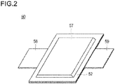
- Fig. 1 is a cross-sectional schematic view which schematically illustrates the overall structure of a flat type (stacked type) lithium ion secondary battery (hereinafter, also simply referred to as the "stacked type battery") of a representative embodiment of the electric device according to the present invention.
- stacked type battery lithium ion secondary battery
- a stacked type battery 10 of the present embodiment has a structure in which a substantially rectangular power generating element 21 in which a charge and discharge reaction actually proceeds is sealed in the interior of a laminate sheet 29 of an outer package.
- the power generating element 21 is configured to stack a positive electrode in which a positive electrode active material layer 15 is disposed on both sides of a positive electrode current collector 12, an electrolyte layer 17, and a negative electrode in which a negative electrode active material layer 13 is disposed on both sides of a negative electrode current collector 11.
- the negative electrode, the electrolyte layer, and the positive electrode are stacked in this order such that one positive electrode active material layer 15 and the adjacent negative electrode active material layer 13 face each other via the electrolyte layer 17.
- the adjacent positive electrode, electrolyte layer, and negative electrode constitute one single battery layer 19.
- the stacked type battery 10 illustrated in Fig. 1 has a configuration in which a plurality of single battery layers 19 are stacked to be electrically connected in parallel.
- the positive electrode active material layer 15 is disposed only on one side of each of the outermost positive electrode current collectors to be positioned at both outermost layers of the power generating element 21, but the active material layer may be provided on both sides thereof. That is, a current collector which has an active material layer only on one side and is thus dedicated to the outermost layer is not prepared but a current collector having an active material layer on both sides may be used as it is as the outermost current collector.
- the positive electrode and the negative electrode may be reversely disposed from Fig. 1 so that the outermost negative electrode current collector is positioned at both outermost layers of the power generating element 21, and the negative electrode active material layer may be disposed on one side or both sides of the outermost negative electrode current collector.
- a positive electrode current collecting plate 27 and a negative electrode current collecting plate 25 which are electrically connected to the respective electrodes have a structure in which they are respectively attached to the positive electrode current collector 12 and the negative electrode current collector 11 and led to the outside of the laminate sheet 29 so as to be sandwiched between the end portions of the laminate sheet 29.
- the positive electrode current collecting plate 27 and the negative electrode current collecting plate 25 may be respectively attached to the positive electrode current collector 12 and the negative electrode current collector 11 of the respective electrodes via a positive electrode lead and a negative electrode lead (not illustrated) by ultrasonic welding, resistance welding, or the like if necessary.
- the lithium ion secondary battery described above is characterized by a negative electrode.
- the important constituent members of the battery including the negative electrode will be described below.
- the active material layer 13 or 15 contains an active material, and it further contains other additives if necessary.
- the positive electrode active material layer 15 contains a positive electrode active material.
- the positive electrode active material may include lithium-transition metal composite oxides such as LiMn 2 O 4 , LiCoO 2 , LiNiO 2 , Li(Ni-Mn-Co)O 2 , and those in which a part of these transition metals are substituted with other elements, lithium-transition metal phosphate compounds, and lithium-transition metal sulfate compounds. Depending on the cases, two or more kinds of positive electrode active materials may be used concurrently.
- a lithium-transition metal composite oxide is preferably used as the positive electrode active material from the viewpoint of capacity and output characteristics.
- a composite oxide containing lithium and nickel is more preferably used, and Li (Ni-Mn-Co) O 2 and those in which a part of these transition metals are substituted with other elements (hereinafter, also simply referred to as the "NMC composite oxide”) are still more preferably used.
- the NMC composite oxide has a layered crystal structure in which a lithium atom layer and a transition metal (Mn, Ni, and Co are orderly disposed) atom layer are alternately stacked via an oxygen atom layer, one Li atom is contained per one atom of the transition metal M, the amount of Li that can be taken out is twofold that of spinel type lithium manganese oxide, that is, the supply ability is twofold, and the NMC composite oxide can thus have a high capacity.
- the NMC composite oxide also includes a composite oxide in which a part of the transition metal elements is substituted with other metal elements.
- the other elements in that case may include Ti, Zr, Nb, W, P, Al, Mg, V, Ca, Sr, Cr, Fe, B, Ga, In, Si, Mo, Y, Sn, V, Cu, Ag, and Zn, the other elements are preferably Ti, Zr, Nb, W, P, Al, Mg, V, Ca, Sr, and Cr, the other elements are more preferably Ti, Zr, P, Al, Mg, and Cr, and from the viewpoint of improving the cycle characteristics, the other elements are still more preferably Ti, Zr, Al, Mg and Cr.
- M is at least one kind of element selected from Ti, Zr, Nb, W, P, Al, Mg, V, Ca, Sr, or Cr) since the theoretical discharge capacity is high.
- a represents the atomic ratio of Li
- b represents the atomic ratio of Ni
- c represents the atomic ratio of Mn
- d represents the atomic ratio of Co
- x represents the atomic ratio of M.
- the composition of the respective elements can be measured by, for example, inductively coupled plasma (ICP) emission spectrometry.
- ICP inductively coupled plasma
- Ni nickel
- Co cobalt
- Mn manganese
- Ti or the like partially substitutes the transition metal in the crystal lattice. From the viewpoint of cycle characteristics, it is preferable that a part of the transition element be substituted with another metal element, and it is particularly preferable that 0 ⁇ x ⁇ 0.3 in General Formula (1).
- the crystal structure is stabilized by a solid solution formed by at least one kind selected from the group consisting of Ti, Zr, Nb, W, P, Al, Mg, V, Ca, Sr, and Cr, and as a result, a decrease in capacity of the battery can be prevented even when charge and discharge are repeated and excellent cycle characteristics can be realized.
- LiNi 0.5 Mn 0.3 CO 0.2 O 2 has a greater capacity per unit weight as compared to LiCoO 2 , LiMn 2 O 4 , LiNi 1/3 Mn 1/3 Co 1/3 O 2 , and the like that have been proven in general consumer batteries, can improve the energy density, and thus has an advantage of being able to be used in fabrication of a compact and high capacity battery, and it is also preferable from the viewpoint of the cruising distance.
- LiNi 0.8 Co 0.1 Al 0.1 O 2 is more advantageous from the viewpoint of a greater capacity, but it has a disadvantage from the viewpoint of lifespan characteristics.
- LiNi 0.5 Mn 0.3 CO 0.2 O 2 exhibits excellent lifespan characteristics comparable to LiNi 1/3 Mn 1/3 Co 1/3 O 2 .
- a lithium-transition metal composite oxide is preferably used as the positive electrode active material from the viewpoint of capacity and output characteristics. Incidentally, it is needless to say that a positive electrode active material other than those described above may be used.
- the average particle diameter of the positive electrode active material contained in the positive electrode active material layer 15 is not particularly limited, but it is preferably from 1 to 30 ⁇ m and more preferably from 5 to 20 ⁇ m from the viewpoint of increasing the output.
- particle diameter means the longest distance among the distances between arbitrary two points on the contour line of the active material particle (observation plane) to be observed by using an observation means such as a scanning electron microscope (SEM) or a transmission electron microscope (TEM).
- average particle diameter a value calculated as an average value of the particle diameters of particles to be observed in several to several tens of visual fields by using an observation means such as a scanning electron microscope (SEM) or a transmission electron microscope (TEM) is adopted.
- SEM scanning electron microscope
- TEM transmission electron microscope
- the particle diameter and average particle diameter of other constituent components can also be defined in the same manner.
- the positive electrode active material layer 15 can contain a binder.
- a binder is added for the purpose of binding the active materials with each other or the active material with the current collector and thus maintaining the electrode structure.
- the binder to be used in the positive electrode active material layer is not particularly limited, but examples thereof may include the following materials.
- Thermoplastic polymers such as polyethylene, polypropylene, polyethylene terephthalate (PET), polyether nitrile (PEN), polyacrylonitrile, polyimide, polyamide, polyamide-imide, cellulose, carboxymethyl cellulose (CMC), an ethylene-vinyl acetate copolymer, polyvinyl chloride, styrene-butadiene rubber (SBR), isoprene rubber, butadiene rubber, ethylene-propylene rubber, an ethylene-propylene-diene copolymer, a styrene-butadiene-styrene block copolymer and any hydrogenated product thereof, and a styrene-isoprene-sty
- polyvinylidene fluoride, polyimide, styrene-butadiene, carboxymethyl cellulose, polypropylene, polytetrafluoroethylene, polyacrylonitrile, polyamide, and polyamide-imide are more preferable.
- These suitable binders exhibit excellent heat resistance, further have a significantly wide potential window, are stable to both the positive electrode potential and the negative electrode potential, and can be thus used in the active material layer.
- These binders may be used singly or two kinds thereof may be used concurrently.
- the amount of binder contained in the positive electrode active material layer is not particularly limited as long as it is an amount in which the active material can be bound, but it is preferably from 0.5 to 15% by mass and more preferably from 1 to 10% by mass relative to the active material layer.
- the positive electrode (positive electrode active material layer) can be formed by any method of a kneading method, a sputtering method, a vapor deposition method, a CVD method, a PVD method, an ion plating method, or a thermal spraying method in addition to an ordinary method to coat a slurry.
- the negative electrode active material layer 13 contains a negative electrode active material.
- the negative electrode active material contains as a main component a silicon-containing alloy having a structure in which a silicide phase containing a silicide of a transition metal is dispersed in a parent phase containing amorphous or low crystalline silicon as a main component and having a predetermined composition.
- the silicon-containing alloy constituting the negative electrode active material in the present embodiment contains a parent phase containing amorphous or low crystalline silicon as a main component.
- a parent phase containing amorphous or low crystalline silicon as a main component.
- the parent phase constituting the silicon-containing alloy is a phase containing silicon as a main component, and it is preferably a Si single phase (a phase composed only of Si).
- This parent phase (a phase containing Si as a main component) is a phase involved in occlusion and release of lithium ions at the time of operation of the electric device (lithium ion secondary battery) of the present embodiment, and it is a phase capable of electrochemically reacting with Li.
- a Si single phase it is possible to occlude and release a large amount of Li per unit weight and per unit volume.
- Si exhibits poor electron conductivity, and the parent phase may thus contain trace amounts of additive elements such as phosphorus and boron, transition metals, and the like.
- this parent phase (a phase containing Si as a main component) is more amorphized than the silicide phase to be described later.
- the negative electrode active material silicon-containing alloy
- the silicon-containing alloy constituting the negative electrode active material in the present embodiment also contains a silicide phase which is dispersed in the parent phase and contains a silicide (also referred to as a silicide) of a transition metal.
- This silicide phase contains a silicide of a transition metal (for example, TiSi 2 ) so as to exhibit excellent affinity for the parent phase and to be able to suppress cracking at the crystal interface particularly due to volume expansion at the time of charge.
- the silicide phase is superior to the parent phase in electron conductivity and hardness. For this reason, the silicide phase improves low electron conductivity of the parent phase and also plays a role of maintaining the shape of the active material against the stress at the time of expansion.
- a plurality of phases may be present in the silicide phase, and, for example, two or more phases (for example, MSi 2 and MSi) having different composition ratios of the transition metal element M to Si may be present.
- two or more phases may be present by containing silicides of different transition metal elements.
- the kind of the transition metal contained in the silicide phase is not particularly limited, but it is preferably at least one kind selected from the group consisting of Ti, Zr, Ni, Cu, and Fe, more preferably Ti or Zr, and particularly preferably Ti.
- the silicides formed of these elements have higher electron conductivity than silicides of other elements and a high strength.
- TiSi 2 of a silicide in a case in which the transition metal element is Ti is preferable since it exhibits significantly excellent electron conductivity.
- a TiSi 2 phase is 50% by mass or more, preferably 80% by mass or more, more preferably 90% by mass or more, particularly preferably 95% by mass or more, and most preferably 100% by mass of the silicide phase.
- the size of the silicide phase is not particularly limited, but the size of the silicide phase is 50 nm or less in a preferred embodiment.
- the negative electrode active material silicon-containing alloy
- the negative electrode active material can be formed to have a higher capacity.
- the silicon-containing alloy constituting the negative electrode active material has a composition represented by the following Chemical Formula (1).
- Chemical Formula 3 Si x Sn y M z A a
- A is an unavoidable impurity
- M is one or two or more transition metal elements
- the term "an unavoidable impurity” means a component that is present in the raw material or has been unavoidably mixed into the Si-containing alloy during the production process. The unavoidable impurity is not originally required, but it is in a trace amount and does not affect the characteristics of the Si alloy, and it is thus allowable impurity.
- the present embodiment it is possible to suppress the phase transition between an amorphous state and a crystalline state at the time of alloying Si with Li and thus to improve the cycle lifespan particularly by selecting Ti as an additive element (M; a transition metal) to the negative electrode active material (silicon-containing alloy) and adding Sn as a second additive element if necessary.
- M an additive element
- a negative electrode active material is formed to have a higher capacity than a conventional negative electrode active material (for example, carbon-based negative electrode active material).
- Mbe titanium (Ti) in the composition represented by Chemical Formula (1) above it is preferable that Mbe titanium (Ti) in the composition represented by Chemical Formula (1) above.
- the composition represented by Chemical Formula (1) above be a ternary system of Si-Sn-Ti containing titanium as M.
- the reason for suppressing the phase transition between an amorphous state and a crystalline state at the time of alloying Si with Li is because transition from an amorphous state to a crystalline state occurs to cause a great change in volume (about fourfold) at the time of alloying Si with Li in a Si material and thus the particles themselves are broken and lose the function as an active material.
- the phase transition between an amorphous state and a crystalline state it is possible to suppress collapse of the particles themselves, to maintain the function (high capacity) as an active material, and also to improve the cycle lifespan.
- By selecting such an additive element it is possible to provide a Si alloy negative electrode active material having a high capacity and high cycle durability.
- the composition ratio z of the transition metal M (particularly Ti) is preferably 7 ⁇ z ⁇ 100, more preferably 10 ⁇ z ⁇ 100, still more preferably 15 ⁇ z ⁇ 100, and particularly preferably 20 ⁇ z ⁇ 100.
- x, y, and z in Chemical Formula (1) satisfy the following Mathematical Formula (1) or (2).
- Mathematical Formula 1 35 ⁇ x ⁇ 78 , 7 ⁇ y ⁇ 30 , 0 ⁇ z ⁇ 37 35 ⁇ x ⁇ 52 , 30 ⁇ y ⁇ 51 , 0 ⁇ z ⁇ 35
- the content of the transition metal M (particularly Ti) is in a range of more than 7% by mass from the viewpoint of attaining further improvement in characteristics of the negative electrode active material.
- x, y, and z satisfy the following Mathematical Formula (3) or (4).
- Mathematical Formula 2 35 ⁇ x ⁇ 78 , 7 ⁇ y ⁇ 30 , 7 ⁇ z ⁇ 37 35 ⁇ x ⁇ 52 , 30 ⁇ y ⁇ 51 , 7 ⁇ z ⁇ 35
- x, y, and z satisfy the following Mathematical Formula (5) or (6): [Mathematical Formula 3] 35 ⁇ x ⁇ 68 , 7 ⁇ y ⁇ 30 , 18 ⁇ z ⁇ 37 39 ⁇ x ⁇ 52 , 30 ⁇ y ⁇ 51 , 7 ⁇ z ⁇ 20 from the viewpoint of securing more favorable cycle durability.
- x, y, and z satisfy the following Mathematical Formula (7): [Mathematical Formula 4] 46 ⁇ x ⁇ 58 , 7 ⁇ y ⁇ 21 , 24 ⁇ z ⁇ 37 in the negative electrode active material of the present embodiment from the viewpoints of initial discharge capacity and cycle durability.
- A is an impurity (an unavoidable impurity) other than the three components described above, which is derived from raw materials and the production method.
- a is 0 ⁇ a ⁇ 0.5 and preferably 0 ⁇ a ⁇ 0.1.
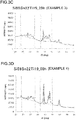
- This ratio value (B/A) is preferably 0.89 or more, more preferably 2.55 or more, and particularly preferably 7.07 or more.
- the X-ray diffraction analysis for calculating the above ratio value of diffraction peaks is conducted by using the method described in the section for Examples to be described later.
- a line segment ab is taken as the base line
- a silicide of a transition metal is TiSi 2
- a line segment ef is taken as the base line
- the specific value of each of the diffraction peak intensity A of the (111) plane of Si and the diffraction peak intensity B of a silicide of a transition metal is not particularly limited, but the diffraction peak intensity A of the (111) plane of Si is preferably from 6000 to 25000 (cps) and more preferably from 6000 to 15000.
- the diffraction peak intensity B of a silicide of a transition metal is preferably from 9000 to 46000 (cps) and more preferably from 25000 to 46000 (cps).
- the particle diameter of the silicon-containing alloy constituting the negative electrode active material in the present embodiment is not particularly limited, but the average particle diameter is preferably from 0.1 to 20 ⁇ m and more preferably from 0.2 to 10 ⁇ m.
- the method of producing the negative electrode active material for electric device according to the present embodiment is not particularly limited, and conventionally known knowledge can be appropriately referred to, but in the present application, as an example of a production method for setting the value of the intensity ratio B/A of diffraction peaks obtained by X-ray diffraction analysis to be in the range as described above, a production method including the following steps is provided.
- a step of mixing raw materials of the silicon-containing alloy to obtain a mixed powder is carried out.
- the raw materials of the alloy are mixed in consideration of the composition of the negative electrode active material (silicon-containing alloy) to be obtained.
- the form and the like thereof are not particularly limited as long as the ratio of elements required as a negative electrode active material can be realized.
- raw materials in a powder form are usually mixed.
- a mixed powder composed of raw materials is obtained.
- it is possible to control the above intensity ratio (B/A) by adjusting the composition ratio of silicon (Si) and titanium (Ti).
- the mixed powder obtained above is subjected to an alloying treatment.
- a silicon-containing alloy that can be used as a negative electrode active material for electric device is obtained.
- a method of alloying treatment there are a solid phase method, a liquid phase method, and a vapor phase method, but examples thereof may include a mechanical alloying method, an arc plasma melting method, a casting method, a gas atomizing method, a liquid quenching method, an ion beam sputtering method, a vacuum deposition method, a plating method, and a vapor phase chemical reaction method.
- a mechanical alloying method an arc plasma melting method, a casting method, a gas atomizing method, a liquid quenching method, an ion beam sputtering method, a vacuum deposition method, a plating method, and a vapor phase chemical reaction method.
- the alloying treatment described above is conducted. This makes it possible to have a structure composed of the parent phase and the silicide phase as described above. It is possible to obtain a negative electrode active material (silicon-containing alloy) capable of exerting desired cycle durability particularly when the time for the alloying treatment (preferably by the mechanical alloying method) is 24 hours or longer.
- the time for the alloying treatment is preferably 30 hours or longer, more preferably 36 hours or longer, still more preferably 42 hours or longer, and particularly preferably 48 hours or longer.
- the intensity ratio (B/A) of the diffraction peak can be increased.
- the upper limit value of the time for the alloying treatment is not particularly set, but it may be usually 72 hours or shorter.
- the alloying treatment by the method described above is usually conducted in a dry atmosphere, but the particle size distribution after the alloying treatment has a wide width from a small size to a large size in some cases. For this reason, it is preferable to conduct a crushing treatment and/or classification treatment to adjust the particle size.
- the predetermined alloy to be essentially contained in the negative electrode active material layer has been described above, but the negative electrode active material layer may contain other negative electrode active materials.
- the negative electrode active material other than the predetermined alloy may include carbon such as natural graphite, artificial graphite, carbon black, activated carbon, carbon fiber, coke, soft carbon, and hard carbon, a pure metal such as Si or Sn, or an alloy-based active material having a composition ratio which deviates from the predetermined composition ratio described above, or a metal oxide such as TiO, Ti 2 O 3 , or TiO 2 or SiO 2 , SiO, or SnO 2 , a composite oxide (a composite nitride) of lithium and a transition metal such as Li 4/3 Ti 5/3 O 4 or Li 7 MnN, Li-Pb alloy, Li-Al alloy, or Li.
- the content of the predetermined alloy in 100% by mass of the total amount of the negative electrode active material is preferably from 50 to 100% by mass, more preferably from 80 to 100% by mass, still more preferably from 90 to 100% by mass, particularly preferably from 95 to 100% by mass, and most preferably 100% by mass.
- the negative electrode active material layer 13 contains a binder.
- the binder is added for the purpose of binding the active materials with each other or the active material with the current collector and thus maintaining the electrode structure.
- the kind of the binder to be used in the negative electrode active material layer is also not particularly limited, and those described above as the binder to be used in the positive electrode active material layer can be used in the same manner. Hence, the detailed description thereon will be omitted here.
- the amount of the binder contained in the negative electrode active material layer is not particularly limited as long as it is an amount in which the active material can be bound, but it is preferably from 0.5 to 20% by mass and more preferably from 1 to 15% by mass relative to the negative electrode active material layer.
- the positive electrode active material layer 15 and the negative electrode active material layer 13 contain an electric conductive auxiliary, an electrolyte salt (lithium salt), an ion conductive polymer, and the like if necessary.
- the negative electrode active material layer 13 essentially contains an electric conductive auxiliary as well.
- the electric conductive auxiliary is an additive to be blended in order to improve the electric conductivity of the positive electrode active material layer or the negative electrode active material layer.
- Examples of the electric conductive auxiliary may include carbon materials such as carbon black such as acetylene black, graphite, and vapor-grown carbon fiber.
- An electronic network which can contribute to improvement of output characteristics of the battery is effectively formed in the interior of the active material layer when the active material layer contains an electric conductive auxiliary.
- the content of the electric conductive auxiliary to be mixed in the active material layer is in a range of 1% by mass or more, more preferably 3% by mass or more, and still more preferably 5% by mass or more relative to the total amount of the active material layer.
- the content of the electric conductive auxiliary to be mixed in the active material layer is in a range of preferably 15% by mass or less, more preferably 10% by mass or less, still more preferably 7% by mass or less relative to the total amount of the active material layer.
- the electron conductivity of the active material itself is low, the electrode resistance can be decreased by the amount of the electric conductive auxiliary, and the following effects are exerted by regulating the blending ratio (content) of the electric conductive auxiliary in the active material layer to be in the above range. That is, it is possible to sufficiently ensure the electron conductivity without hindering the electrode reaction, to suppress a decrease in energy density due to a decrease in electrode density, and thus to attain the improvement in energy density due to the improvement in electrode density.
- an electric conductive binder having the functions of both the electric conductive auxiliary and the binder may be used instead of these electric conductive auxiliary and binder or may be concurrently used with one or both of these electric conductive auxiliary and binder.
- the electric conductive binder commercially available TAB-2 (manufactured by Hohsen Corp.) can be used.
- Examples of the electrolyte salt may include Li(C 2 F 5 SO 2 ) 2 N, LiPF 6 , LiBF 4 , LiClO 4 , LiAsF 6 , and LiCF 3 SO 3 .
- Examples of the ion conductive polymer may include a polyethylene oxide-based (PEO) polymer and a polypropylene oxide-based (PPO) polymer.
- PEO polyethylene oxide-based
- PPO polypropylene oxide-based
- the blending ratio of the components contained in the positive electrode active material layer and the negative electrode active material layer is not particularly limited.
- the blending ratio can be adjusted by appropriately referring to known knowledge on nonaqueous solvent secondary batteries.
- each active material layer (the active material layer on one side of the current collector) is also not particularly limited, and conventionally known knowledge on batteries can be appropriately referred to.
- the thickness of each active material layer is usually about from 1 to 500 ⁇ m and preferably from 2 to 100 ⁇ m in consideration of the intended use (output-oriented, energy-oriented, or the like) of the battery and ion conductivity.
- the current collectors 11 and 12 are composed of an electric conductive material.
- the size of the current collector is determined according to the application of the battery. For example, a current collector having a large area is used when the current collector is used in a large battery requiring a high-energy density.
- the thickness of the current collector is also not particularly limited.
- the thickness of the current collector is usually about from 1 to 100 ⁇ m.
- the shape of the current collector is also not particularly limited.
- a mesh shape expanded grid or the like or the like can be used in addition to the current collector foil.
- a current collecting foil in the case of directly forming a thin film alloy of the negative electrode active material on the negative electrode current collector 11 by a sputtering method or the like.
- the material constituting the current collector is not particularly limited.
- a metal or a resin in which an electric conductive filler is added to an electric conductive polymer material or an electric nonconductive polymer material can be employed.
- examples of the metal may include aluminum, nickel, iron, stainless steel, titanium, and copper.
- a clad material of nickel with aluminum, a clad material of copper with aluminum, a plated material of a combination of these metals, or the like can be preferably used.
- it may be a foil fabricated by covering aluminum on a metal surface.
- aluminum, stainless steel, copper, and nickel are preferable from the viewpoints of electron conductivity, action potential of battery, adhesive property of the negative electrode active material to the current collector by sputtering, and the like.
- examples of the electric conductive polymer material may include polyaniline, polypyrrole, polythiophene, polyacetylene, polyparaphenylene, polyphenylenevinylene, polyacrylonitrile, and polyoxadiazole. Since such an electric conductive polymer material exhibits sufficient electric conductivity even without adding an electric conductive filler thereto and it is thus advantageous from the viewpoint of facilitating the production process or decreasing the weight of the current collector.
- Examples of the electric nonconductive polymer material may include polyethylene (PE; high density polyethylene (HDPE), low density polyethylene (LDPE), and the like), polypropylene (PP), polyethylene terephthalate (PET), polyether nitrile (PEN), polyimide (PI), polyamide-imide (PAI), polyamide (PA), polytetrafluoroethylene (PTFE), styrene-butadiene rubber (SBR), polyacrylonitrile (PAN), polymethyl acrylate (PMA), polymethyl methacrylate (PMMA), polyvinyl chloride (PVC), polyvinylidene fluoride (PVdF), or polystyrene (PS).
- PE polyethylene
- HDPE high density polyethylene
- LDPE low density polyethylene
- PP polypropylene
- PET polyethylene terephthalate
- PEN polyether nitrile
- PI polyimide
- PAI polyamide-imide
- PA polyamide
- PTFE polytetra
- An electric conductive filler may be added to the electric conductive polymer material or electric nonconductive polymer material described above if necessary.
- An electric conductive filler is necessarily essential in order to impart electric conductivity to the resin particularly in a case in which the resin to be the base material of the current collector is composed only of an electric nonconductive polymer.
- the electric conductive filler can be used without being particularly limited as long as it is a substance exhibiting electric conductivity.
- Examples of a material exhibiting excellent electric conductivity, electric potential resistance, or lithium ion shielding property may include metal and electric conductive carbon.
- the metal is not particularly limited, but it is preferable to contain at least one kind of metal selected from the group consisting of Ni, Ti, Al, Cu, Pt, Fe, Cr, Sn, Zn, In, Sb, and K or an alloy or metal oxide containing these metals.
- the electric conductive carbon is not particularly limited. It is preferably one that contains at least one kind selected from the group consisting of acetylene black, vulcan, black pearl, carbon nanofiber, Ketjen black, carbon nanotube, carbon nanohorn, carbon nanoballoon, and fullerene.
- the amount of the electric conductive filler added is not particularly limited as long as it is an amount in which sufficient electric conductivity can be imparted to the current collector, and it is generally about from 5 to 35% by mass.
- electrolyte constituting the electrolyte layer 17 a liquid electrolyte or a polymer electrolyte can be used.
- the liquid electrolyte has a form in which a lithium salt (electrolyte salt) is dissolved in an organic solvent.
- organic solvent may include carbonates such as ethylene carbonate (EC), propylene carbonate (PC), butylene carbonate (BC), vinylene carbonate (VC), dimethyl carbonate (DMC), diethyl carbonate (DEC), ethyl methyl carbonate (EMC), and methyl propyl carbonate (MPC).
- lithium salt it is possible to employ a compound that can be added to the active material layer of an electrode such as Li(CF 3 SO 2 ) 2 N, Li(C 2 F 5 SO 2 ) 2 N, LiPF 6 , LiBF 4 , LiAsF 6 , LiTaF 6 , LiClO 4 , or LiCF 3 SO 3 .
- the polymer electrolyte is classified into a gel electrolyte containing an electrolytic solution and an intrinsic polymer electrolyte which does not contain an electrolytic solution.
- the gel electrolyte has a configuration in which the liquid electrolyte (electrolytic solution) is injected into a matrix polymer composed of an ion conductive polymer. It is excellent to use a gel polymer electrolyte as the electrolyte from the viewpoint that the fluidity of the electrolyte is eliminated and ionic conduction between the respective layers is easily shielded.
- Examples of the ion conductive polymer to be used as the matrix polymer may include polyethylene oxide (PEO), polypropylene oxide (PPO), and a copolymer thereof.
- PEO polyethylene oxide
- PPO polypropylene oxide
- Such a polyalkylene oxide-based polymer can readily dissolve an electrolyte salt such as a lithium salt.
- the proportion of the liquid electrolyte (electrolytic solution) in the gel electrolyte is not particularly limited, but it is preferably set to about several percent by mass to 98% by mass from the viewpoint of ionic conductivity and the like. In the present embodiment, there is an effect particularly for a gel electrolyte containing a large amount of electrolytic solution, namely, having a proportion of the electrolytic solution of 70% by mass or more.
- a separator may be used in the electrolyte layer in a case in which the electrolyte layer is composed of a liquid electrolyte, a gel electrolyte, or an intrinsic polymer electrolyte.
- the specific form of the separator may include a microporous membrane formed of a polyolefin such as polyethylene or polypropylene, a porous flat plate, or a nonwoven fabric.
- the intrinsic polymer electrolyte has a configuration in which a supporting salt (lithium salt) is dissolved in the matrix polymer described above, and it does not contain an organic solvent as a plasticizer. Hence, liquid leakage from the battery is not concerned and the reliability of the battery can be improved in a case in which the electrolyte layer is composed of the intrinsic polymer electrolyte.
- a matrix polymer of the gel electrolyte or the intrinsic polymer electrolyte can exert excellent mechanical strength by forming a crosslinked structure.
- a polymerizable polymer for example, PEO or PPO
- a polymerization treatment such as heat polymerization, ultraviolet polymerization, radiation polymerization, or electron beam polymerization using a proper polymerization initiator.
- a current collecting plate may be used for the purpose of taking out the electric current to the outside of the battery.
- the current collecting plate is electrically connected to the current collector and the lead and brought out to the outside of the laminate sheet of the battery outer packaging material.
- the material constituting the current collecting plate is not particularly limited and a known highly electric conductive material which is conventionally used as a current collecting plate for lithium ion secondary battery can be used.
- a known highly electric conductive material which is conventionally used as a current collecting plate for lithium ion secondary battery can be used.
- the material constituting the current collecting plate for example, metal materials such as aluminum, copper, titanium, nickel, stainless steel (SUS), and any alloy thereof are preferable, and aluminum, copper, and the like are more preferable from the viewpoint of light weight, corrosion resistance, and high electric conductivity.
- the same material or different materials may be used in the positive electrode current collecting plate and the negative electrode current collecting plate.
- a positive terminal lead and a negative terminal lead are used if necessary.
- a known terminal lead that is used in a lithium ion secondary battery can be used.
- the portion to be brought out from a battery outer packaging material 29 be covered with a heat-shrinkable tube or the like exhibiting heat resistance and insulation property so as not to affect the products (for example, automotive parts and especially electronic devices) by coming in contact with peripheral devices, wires, and the like and thus causing a short circuit.
- the battery outer packaging material 29 it is possible to use a bag-shaped case which can cover the power generating element and uses a laminate film containing aluminum in addition to a known metal can case.
- a laminate film for example, a laminate film having a three-layer structure formed by laminating PP, aluminum, and nylon in this order, or the like can be used, but the laminate film is not limited to these.
- a laminate film is preferable from the viewpoint of having a high output and cooling performance and being able to be suitably utilized in a battery for large device for EV and HEV.
- the lithium ion secondary battery can be produced by a conventionally known production method.
- Fig. 2 is a perspective view which illustrates the appearance of a stacked type flat lithium ion secondary battery.
- a stacked type flat lithium ion secondary battery 50 has a rectangular flat shape, and a positive electrode current collecting plate 59 and a negative electrode current collecting plate 58 for taking out electric power are pulled out from both side portions thereof.
- a power generating element 57 is wrapped in a battery outer packaging material 52 of the lithium ion secondary battery 50, the periphery of the battery outer packaging material 52 is heat-sealed, and the power generating element 57 is hermetically sealed in a state in which the positive electrode current collecting plate 59 and the negative electrode current collecting plate 58 are pulled out to the outside.
- the power generating element 57 corresponds to the power generating element 21 of the lithium ion secondary battery (stacked type battery) 10 illustrated in Fig. 1 .
- the power generating element 57 is formed by stacking a plurality of single battery layers (single cells) 19 including the positive electrode (positive electrode active material layer) 13, the electrolyte layer 17, and the negative electrode (negative electrode active material layer) 15.
- the lithium ion secondary battery is not limited to a stacked type one having a flat shape (laminate cell).
- the lithium ion secondary battery may be one having a cylindrical shape (coin cell) or one having a prismatic shape (square cell) as a wound type lithium ion battery, one obtained by deforming the one having a cylindrical shape to have a rectangular flat shape, and further a cylindrical cell, and it is not particularly limited.
- a laminate film or a conventional cylindrical can (metal can) may be used as the outer packaging material thereof, and the outer packaging material is not particularly limited.
- the power generating element is packaged in an aluminum laminate film. The weight saving can be achieved by this form.
- bringing out of the positive electrode current collecting plate 59 and the negative electrode current collecting plate 58 illustrated in Fig. 2 is not also particularly limited.
- the positive electrode current collecting plate 59 and the negative electrode current collecting plate 58 may be pulled out from the same side or each of the positive electrode current collecting plate 59 and the negative electrode current collecting plate 58 may be divided into a plurality of pieces and taken out from each side, and the bringing out is not limited to that illustrated in Fig. 2 .
- terminals may be formed by utilizing, for example, a cylindrical can (metal can) instead of a current collecting plate.
- the negative electrode and the lithium ion secondary battery which are formed by using the negative electrode active material for lithium ion secondary battery of the present embodiment can be suitably utilized as a large capacity power source for electric vehicles, hybrid electric vehicles, fuel cell vehicles, hybrid fuel cell vehicles, and the like. That is, they can be suitably utilized in a vehicle driving power source and an auxiliary power source which are required to have a high-volume energy density and a high-volume output density.
- a lithium ion battery has been exemplified as an electric device, but the present invention is not limited thereto, and the negative electrode active material can also be applied to secondary batteries of other types and even primary batteries. In addition, it can be applied not only to batteries but also to capacitors.
- a silicon-containing alloy (Si 80 Sn 10 Ti 10 ) (unit: % by mass, the same applies hereinafter) was produced by a mechanical alloying method. Specifically, by using a planetary ball mill apparatus P-6 manufactured by Fritsch GmbH, zirconia crushing balls and raw material powders of the alloy were put in a zirconia crushing pot, alloyed at 600 rpm for 24 hours (alloying treatment), and then subjected to a crushing treatment at 400 rpm for 1 hour. Incidentally, the average particle diameter of the silicon-containing alloy (negative electrode active material) powder thus obtained was 0.3 ⁇ m.
- the negative electrode thus fabricated and the counter electrode Li were allowed to face each other, and a separator (Polyolefin, film thickness: 20 ⁇ m) was disposed therebetween. Subsequently, the stacked body of the negative electrode, the separator, and the counter electrode Li was disposed on the bottom side of a coin cell (CR 2032, material: stainless steel (SUS 316)). Furthermore, a gasket was fitted to maintain the insulation between the positive electrode and the negative electrode, the following electrolytic solution was injected by using a syringe, a spring and a spacer were stacked thereon, the upper side of the coin cell was superimposed thereon, and caulking was conducted to hermetically seal the coin cell, thereby obtaining a lithium ion secondary battery.
- a separator Polyolefin, film thickness: 20 ⁇ m
- LiPF 6 lithium hexafluorophosphate
- DEC diethyl carbonate
- a negative electrode active material, a negative electrode, and a lithium ion secondary battery (coin cell) were prepared by the same method as in Example 1 described above except that the composition of the silicon-containing alloy was changed to Si 70 Sn 15 Ti 15 . Incidentally, the average particle diameter of the silicon-containing alloy (negative electrode active material) powder thus obtained was 0.3 ⁇ m.
- a negative electrode active material, a negative electrode, and a lithium ion secondary battery (coin cell) were prepared by the same method as in Example 1 described above except that the composition of the silicon-containing alloy was changed to Si 59 Sn 22 Ti 19 and the time for the alloying treatment when preparing the silicon-containing alloy was changed to 25 hours.
- the average particle diameter of the silicon-containing alloy (negative electrode active material) powder thus obtained was 0.3 ⁇ m.
- a negative electrode active material, a negative electrode, and a lithium ion secondary battery (coin cell) were prepared by the same method as in Example 3 described above except that the time for the alloying treatment when preparing the silicon-containing alloy was changed to 50 hours. Incidentally, the average particle diameter of the silicon-containing alloy (negative electrode active material) powder thus obtained was 0.3 ⁇ m.
- a negative electrode active material, a negative electrode, and a lithium ion secondary battery (coin cell) were prepared by the same method as in Example 1 described above except that the composition of the silicon-containing alloy was changed to Si 90 Ti 10 . Incidentally, the average particle diameter of the silicon-containing alloy (negative electrode active material) powder thus obtained was 0.3 ⁇ m.
- the textural structure of the negative electrode active material (silicon-containing alloy) prepared in each of Examples 1 to 4 and Comparative Example was analyzed by the electron diffraction method, as a result, diffraction spots and halo patterns indicating the crystallinity of the silicide phase (TiSi 2 ) were observed in any of Examples 1 to 4 and Comparative Example, and it was confirmed that the negative electrode active materials had a textural structure in which a crystalline silicide phase was dispersed in the amorphous Si phase of the parent phase.
- the crystalline structure of the negative electrode active material (silicon-containing alloy) prepared in each of Examples 1 to 4 and Comparative Example was analyzed by the X-ray diffraction measurement method.
- the apparatus and conditions used in the X-ray diffraction measurement method are as follows.
- X-ray diffraction spectra obtained for each of the negative electrode active materials (Si-containing alloys) of Examples 1 to 4 and Comparative Example are illustrated in Figs. 3A to 3E .
- the value of diffraction peak intensity A of the (111) plane of Si in a range of 2 ⁇ 24 to 33°
- the value of diffraction peak intensity B of TiSi 2 in a range of 2 ⁇ 37 to 45°
- the ratio value (B/A) of these values obtained from these X-ray diffraction spectra are presented in the following Table 1.
- Table 1 it has also been confirmed that the entire Ti contained in the silicon-containing alloy is present as a silicide (TiSi 2 ) phase by this X-ray diffraction analysis.
- the evaluation cell was charged from 2 V to 10 mV at 0.1 mA in a constant current and constant voltage mode in a thermostatic chamber set at the above evaluation temperature by using a charge and discharge tester in the charge process (referred to as the process of intercalating Li into the evaluation electrode). Thereafter, the evaluation cell (coin cell) was discharged from 10 mV to 2 V at 0.3 C in a constant current mode in the discharge process (referred to as the process of deintercalating Li from the evaluation electrode) .
- the charge and discharge cycle described above was taken as one cycle, and charge and discharge test was conducted from the initial cycle (1st cycle) to the 50th cycle under the same charge and discharge conditions.
Landscapes
- Chemical & Material Sciences (AREA)
- Chemical Kinetics & Catalysis (AREA)
- Electrochemistry (AREA)
- General Chemical & Material Sciences (AREA)
- Engineering & Computer Science (AREA)
- Materials Engineering (AREA)
- Manufacturing & Machinery (AREA)
- Composite Materials (AREA)
- Mechanical Engineering (AREA)
- Metallurgy (AREA)
- Organic Chemistry (AREA)
- Battery Electrode And Active Subsutance (AREA)
- Electric Double-Layer Capacitors Or The Like (AREA)
Abstract
Description
- The present invention relates to a negative electrode active material for electric device, and an electric device using the same. The negative electrode active material for electric device and the electric device using the same according to the present invention are used in a driving power source and an auxiliary power source for motors of vehicles such as electric vehicles, fuel cell vehicles, and hybrid electric vehicles as secondary batteries, capacitors, and the like.
- In recent years, cut down of the amount of carbon dioxide has been ardently desired in order to cope with air pollution and global warming. In the motor vehicle industry, cut down of carbon dioxide emissions due to introduction of electric vehicles (EV) and hybrid electric vehicles (HEV) has been highly expected, and development of electric devices such as secondary batteries for driving motors, which hold the key to practical use of these has been actively carried out.
- The secondary batteries for driving motors are required to exhibit extremely high-output characteristics and high energy as compared to consumer lithium ion secondary batteries to be used in mobile phones, notebook computers, and the like. Hence, lithium ion secondary batteries having the highest theoretical energy among all the batteries have attracted attention, and development thereof is rapidly advanced at present.
- A lithium ion secondary battery generally has a configuration in which a positive electrode in which a positive electrode active material and the like are coated on both sides of a positive electrode current collector by using a binder and a negative electrode in which a negative electrode active material and the like are coated on both sides of a negative electrode current collector by using a binder are connected to each other via an electrolyte layer and housed in a battery case.
- Hitherto, a carbon and graphite-based material, which is advantageous from the viewpoint of lifespan of charge and discharge cycles and cost, has been used in the negative electrode of a lithium ion secondary battery. However, in the case of a carbon and graphite-based negative electrode material, charge and discharge proceed by occlusion and release of lithium ions into and from the graphite crystals, and there is thus a disadvantage that a charge and discharge capacity that is equal to or higher than the theoretical capacity, 372 mAh/g, to be obtained from LiC6 of the maximum lithium-introduced compound is not obtained. For this reason, it is difficult to obtain a capacity and an energy density which satisfy the practical use level of a vehicle application from a carbon and graphite-based negative electrode material.
- In contrast, a battery using a material to be alloyed with Li in the negative electrode is expected as a negative electrode material in a vehicle application since the energy density is improved as compared to a conventional carbon and graphite-based negative electrode material. For example, a Si material occludes and releases 3.75 mol of lithium ions per 1 mol as in the following Reaction Formula (A) in charge and discharge, and the theoretical capacity is 3600 mAh/g in Li15Si4 (= Li3.75Si).
[Chemical Formula 1]
Si + 3.75Li+ + e- ⇄ Li3.75Si (A)
- However, in a lithium ion secondary battery using a material to be alloyed with Li in the negative electrode, expansion and contraction of the negative electrode at the time of charge and discharge is great. For example, the volume expansion in the case of occluding a Li ion is about 1.2 times for a graphite material, but a great volume change (about 4 times) occurs for the Si material since the amorphous state is converted to a crystalline state when Si and Li are alloyed, and there is thus a problem that the cycle lifespan of the electrode decreases. In addition, in the case of a Si negative electrode active material, the capacity and the cycle durability have a trade-off relationship, and there is thus a problem that it is difficult to improve the cycle durability while having a high capacity.
- Here,
Patent Literature 1 discloses an invention aimed to provide a nonaqueous electrolyte secondary battery including a negative electrode pellet having a high capacity and an excellent cycle lifespan. Specifically, a silicon-containing alloy is disclosed which is obtained by mixing and wet pulverizing a silicon powder and a titanium powder by a mechanical alloying method and in which a material including a first phase containing silicon as a main body and a second phase containing a silicide of titanium (TiSi2 or the like) is used as a negative electrode active material. It is also disclosed that at least either of these two phases is amorphous or low crystalline. - Patent Literature 1:
WO 2006/129415 A - According to the investigations of the present inventors, in an electric device such as a lithium ion secondary battery using the negative electrode pellet described in
Patent Literature 1, it has been revealed that the cycle durability is not sufficient in some cases even though it is described that favorable cycle durability can be exhibited. - Accordingly, an object of the present invention is to provide a means capable of improving the cycle durability of an electric device such as a lithium ion secondary battery.
- In order to solve the above problems, the present inventors have carried out intensive researches. As a result, it has been found out that the above problems can be solved by controlling the relationship between the diffraction peak intensity of the (111) plane of Si in a specific wavelength range and the diffraction peak intensity of a silicide of a transition metal in a specific wavelength range in the X-ray diffraction measurement of the silicon-containing alloy in a negative electrode active material including a silicon-containing alloy having a structure in which a silicide phase containing a silicide of a transition metal is dispersed in a parent phase containing amorphous or low crystalline silicon as a main component and a predetermined composition, whereby the present invention has been completed.
- That is, the present invention relates to a negative electrode active material for electric device. The negative electrode active material for electric device includes a silicon-containing alloy having a structure in which a silicide phase containing a silicide of a transition metal is dispersed in a parent phase containing amorphous or low crystalline silicon as a main component and a composition represented by the following Chemical Formula (1):
[Chemical Formula 2]
SixSnyMzAa (1)
- (in Chemical Formula (1) above, A is an unavoidable impurity,
- M is one or two or more transition metal elements,
- x, y, z, and a represent values in terms of percent by mass, and
- 0 < x < 100, 0 ≤ y < 100, 0 < z < 100, and 0 ≤ a < 0.5 and x + y + z + a = 100). Moreover, in the negative electrode active material for electric device, a ratio value (B/A) of a diffraction peak intensity B of a silicide of a transition metal in a range of 2θ = 37 to 45° to a diffraction peak intensity A of a (111) plane of Si in a range of 2θ = 24 to 33° is 0.41 or more in an X-ray diffraction measurement of the silicon-containing alloy using a CuKα1 ray.
- According to the present invention, the phase transition between an amorphous state and a crystalline state (crystallization into Li15Si4) when Si is alloyed with Li can be suppressed as the value of B/A is in the range described above. This can suppress expansion and contraction of the silicon-containing alloy constituting the negative electrode active material in a charge and discharge process of the electric device. As a result, the cycle durability of the electric device using this negative electrode active material can be improved.
-
-
Fig. 1 is a cross-sectional schematic view which schematically illustrates the outline of a stacked type flat non-bipolar lithium ion secondary battery of a representative embodiment of an electric device according to the present invention. -
Fig. 2 is a perspective view which schematically illustrates the outer appearance of a stacked type flat lithium ion secondary battery of a representative embodiment of an electric device according to the present invention. -
Fig. 3A illustrates a diffraction spectrum of a silicon-containing alloy (negative electrode active material) powder obtained in Example 1 obtained by X-ray diffraction analysis. -
Fig. 3B illustrates a diffraction spectrum of a silicon-containing alloy (negative electrode active material) powder obtained in Example 2 obtained by X-ray diffraction analysis. -
Fig. 3C illustrates a diffraction spectrum of a silicon-containing alloy (negative electrode active material) powder obtained in Example 3 obtained by X-ray diffraction analysis. -
Fig. 3D illustrates a diffraction spectrum of a silicon-containing alloy (negative electrode active material) powder obtained in Example 4 obtained by X-ray diffraction analysis. -
Fig. 3E illustrates a diffraction spectrum of a silicon-containing alloy (negative electrode active material) powder obtained in Comparative Example obtained by X-ray diffraction analysis. - Hereinafter, embodiments of a negative electrode active material for electric device and an electric device using the same of the present invention will be described with reference to the drawings. However, the technical scope of the present invention should be determined based on the description of claims and is not limited to only the following embodiments. Incidentally, in the description of the drawings, the same elements are denoted by the same reference numerals, and duplicate descriptions are omitted. In addition, the dimensional ratios of the drawings are exaggerated for convenience of description and may differ from actual ratios.
- Hereinafter, a basic configuration of an electric device to which the negative electrode active material for electric device of the present invention can be applied will be described with reference to the drawings. In the present embodiment, a lithium ion secondary battery will be described as an example of the electric device.
- First, in a negative electrode for lithium ion secondary battery of a representative embodiment of a negative electrode containing the negative electrode active material for electric device according to the present invention, and a lithium ion secondary battery using the same, the voltage of the cell (single battery layer) is great and a high-energy density and a high-output density can be achieved. For this reason, a lithium ion secondary battery using the negative electrode active material for lithium ion secondary battery of the present embodiment is excellent for driving power source and auxiliary power source of a vehicle. As a result, it can be suitably used as a lithium ion secondary battery for driving power and the like of a vehicle. In addition to this, it can also be sufficiently applied to a lithium ion secondary battery for mobile devices such as mobile phones.
- That is, the lithium ion secondary battery to be a target of the present embodiment may be one that is formed by using the negative electrode active material for lithium ion secondary battery of the present embodiment to be described below, and other constituent requirements thereof are not particularly limited.
- For example, in the case of distinguishing the lithium ion secondary battery by the form and structure, it can be applied to any conventionally known form and structure such as a stacked type (flat type) battery and a wound type (cylindrical type) battery. It is advantageous to employ a stacked type (flat type) battery structure from the viewpoint of cost and workability since long-term reliability can be secured by a simple sealing technique such as thermocompression bonding.
- In addition, in the case of considering the electrical connection form (electrode structure) in the lithium ion secondary battery, the lithium ion secondary battery can be applied to both a non-bipolar (internal parallel connection type) battery and a bipolar (internal series connection type) battery.
- In the case of distinguishing the lithium ion secondary battery by the type of the electrolyte layer therein, the lithium ion secondary battery can also be applied to batteries having any conventionally known type of electrolyte layer such as a solution electrolyte type battery using a solution electrolyte such as a nonaqueous electrolytic solution in the electrolyte layer and a polymer battery using a polymer electrolyte in the electrolyte layer. The polymer battery is classified into a gel electrolyte type battery using a polymer gel electrolyte (also simply referred to as a gel electrolyte) and a solid polymer (all-solid) type battery using a polymer solid electrolyte (also simply referred to as a polymer electrolyte).
- Accordingly, in the following description, a non-bipolar (internal parallel connection type) lithium ion secondary battery using the negative electrode active material for lithium ion secondary battery of the present embodiment will be significantly briefly described with reference to the drawings. However, the technical scope of the lithium ion secondary battery of the present embodiment is not limited to these.
-
Fig. 1 is a cross-sectional schematic view which schematically illustrates the overall structure of a flat type (stacked type) lithium ion secondary battery (hereinafter, also simply referred to as the "stacked type battery") of a representative embodiment of the electric device according to the present invention. - As illustrated in
Fig. 1 , astacked type battery 10 of the present embodiment has a structure in which a substantially rectangularpower generating element 21 in which a charge and discharge reaction actually proceeds is sealed in the interior of alaminate sheet 29 of an outer package. Here, thepower generating element 21 is configured to stack a positive electrode in which a positive electrodeactive material layer 15 is disposed on both sides of a positive electrodecurrent collector 12, anelectrolyte layer 17, and a negative electrode in which a negative electrodeactive material layer 13 is disposed on both sides of a negative electrodecurrent collector 11. Specifically, the negative electrode, the electrolyte layer, and the positive electrode are stacked in this order such that one positive electrodeactive material layer 15 and the adjacent negative electrodeactive material layer 13 face each other via theelectrolyte layer 17. - By this, the adjacent positive electrode, electrolyte layer, and negative electrode constitute one
single battery layer 19. Hence, it can also be said that thestacked type battery 10 illustrated inFig. 1 has a configuration in which a plurality of single battery layers 19 are stacked to be electrically connected in parallel. Incidentally, the positive electrodeactive material layer 15 is disposed only on one side of each of the outermost positive electrode current collectors to be positioned at both outermost layers of thepower generating element 21, but the active material layer may be provided on both sides thereof. That is, a current collector which has an active material layer only on one side and is thus dedicated to the outermost layer is not prepared but a current collector having an active material layer on both sides may be used as it is as the outermost current collector. In addition, the positive electrode and the negative electrode may be reversely disposed fromFig. 1 so that the outermost negative electrode current collector is positioned at both outermost layers of thepower generating element 21, and the negative electrode active material layer may be disposed on one side or both sides of the outermost negative electrode current collector. - A positive electrode
current collecting plate 27 and a negative electrodecurrent collecting plate 25 which are electrically connected to the respective electrodes (the positive electrode and the negative electrode) have a structure in which they are respectively attached to the positive electrodecurrent collector 12 and the negative electrodecurrent collector 11 and led to the outside of thelaminate sheet 29 so as to be sandwiched between the end portions of thelaminate sheet 29. The positive electrodecurrent collecting plate 27 and the negative electrodecurrent collecting plate 25 may be respectively attached to the positive electrodecurrent collector 12 and the negative electrodecurrent collector 11 of the respective electrodes via a positive electrode lead and a negative electrode lead (not illustrated) by ultrasonic welding, resistance welding, or the like if necessary. - The lithium ion secondary battery described above is characterized by a negative electrode. The important constituent members of the battery including the negative electrode will be described below.
- The
active material layer - The positive electrode
active material layer 15 contains a positive electrode active material. - Examples of the positive electrode active material may include lithium-transition metal composite oxides such as LiMn2O4, LiCoO2, LiNiO2, Li(Ni-Mn-Co)O2, and those in which a part of these transition metals are substituted with other elements, lithium-transition metal phosphate compounds, and lithium-transition metal sulfate compounds. Depending on the cases, two or more kinds of positive electrode active materials may be used concurrently. A lithium-transition metal composite oxide is preferably used as the positive electrode active material from the viewpoint of capacity and output characteristics. A composite oxide containing lithium and nickel is more preferably used, and Li (Ni-Mn-Co) O2 and those in which a part of these transition metals are substituted with other elements (hereinafter, also simply referred to as the "NMC composite oxide") are still more preferably used. The NMC composite oxide has a layered crystal structure in which a lithium atom layer and a transition metal (Mn, Ni, and Co are orderly disposed) atom layer are alternately stacked via an oxygen atom layer, one Li atom is contained per one atom of the transition metal M, the amount of Li that can be taken out is twofold that of spinel type lithium manganese oxide, that is, the supply ability is twofold, and the NMC composite oxide can thus have a high capacity.
- As described above, the NMC composite oxide also includes a composite oxide in which a part of the transition metal elements is substituted with other metal elements. Examples of the other elements in that case may include Ti, Zr, Nb, W, P, Al, Mg, V, Ca, Sr, Cr, Fe, B, Ga, In, Si, Mo, Y, Sn, V, Cu, Ag, and Zn, the other elements are preferably Ti, Zr, Nb, W, P, Al, Mg, V, Ca, Sr, and Cr, the other elements are more preferably Ti, Zr, P, Al, Mg, and Cr, and from the viewpoint of improving the cycle characteristics, the other elements are still more preferably Ti, Zr, Al, Mg and Cr.
- The NMC composite oxide preferably has a composition represented by General Formula (1) : LiaNibMncCOdMxO2 (where a, b, c, d, and x satisfy 0.9 ≤ a ≤ 1.2, 0 < b < 1, 0 < c ≤ 0.5, 0 < d ≤ 0.5, 0 ≤ x ≤ 0.3, and b + c + d = 1. M is at least one kind of element selected from Ti, Zr, Nb, W, P, Al, Mg, V, Ca, Sr, or Cr) since the theoretical discharge capacity is high. Here, a represents the atomic ratio of Li, b represents the atomic ratio of Ni, c represents the atomic ratio of Mn, d represents the atomic ratio of Co, and x represents the atomic ratio of M. From the viewpoint of cycle characteristics, it is preferable that 0.4 ≤ b ≤ 0.6 be satisfied in General Formula (1). Incidentally, the composition of the respective elements can be measured by, for example, inductively coupled plasma (ICP) emission spectrometry.
- In general, it is known that nickel (Ni), cobalt (Co), and manganese (Mn) contribute to the capacity and output characteristics from the viewpoint of improving purity of the material and improving electron conductivity. Ti or the like partially substitutes the transition metal in the crystal lattice. From the viewpoint of cycle characteristics, it is preferable that a part of the transition element be substituted with another metal element, and it is particularly preferable that 0 < x ≤ 0.3 in General Formula (1). It is considered that the crystal structure is stabilized by a solid solution formed by at least one kind selected from the group consisting of Ti, Zr, Nb, W, P, Al, Mg, V, Ca, Sr, and Cr, and as a result, a decrease in capacity of the battery can be prevented even when charge and discharge are repeated and excellent cycle characteristics can be realized.
- As a more preferred embodiment, it is preferable that b, c, and d satisfy 0.44 ≤ b ≤ 0.51, 0.27 ≤ c ≤ 0.31, and 0.19 ≤ d ≤ 0.26 in General Formula (1) from the viewpoint of improving the balance between capacity and lifespan characteristics. For example, LiNi0.5Mn0.3CO0.2O2 has a greater capacity per unit weight as compared to LiCoO2, LiMn2O4, LiNi1/3Mn1/3Co1/3O2, and the like that have been proven in general consumer batteries, can improve the energy density, and thus has an advantage of being able to be used in fabrication of a compact and high capacity battery, and it is also preferable from the viewpoint of the cruising distance. Incidentally, LiNi0.8Co0.1Al0.1O2 is more advantageous from the viewpoint of a greater capacity, but it has a disadvantage from the viewpoint of lifespan characteristics. In contrast, LiNi0.5Mn0.3CO0.2O2 exhibits excellent lifespan characteristics comparable to LiNi1/3Mn1/3Co1/3O2.
- Depending on the cases, two or more kinds of positive electrode active materials may be used concurrently. A lithium-transition metal composite oxide is preferably used as the positive electrode active material from the viewpoint of capacity and output characteristics. Incidentally, it is needless to say that a positive electrode active material other than those described above may be used.
- The average particle diameter of the positive electrode active material contained in the positive electrode
active material layer 15 is not particularly limited, but it is preferably from 1 to 30 µm and more preferably from 5 to 20 µm from the viewpoint of increasing the output. Incidentally, in the present specification, the term "particle diameter" means the longest distance among the distances between arbitrary two points on the contour line of the active material particle (observation plane) to be observed by using an observation means such as a scanning electron microscope (SEM) or a transmission electron microscope (TEM). In addition, in the present specification, as the value of "average particle diameter", a value calculated as an average value of the particle diameters of particles to be observed in several to several tens of visual fields by using an observation means such as a scanning electron microscope (SEM) or a transmission electron microscope (TEM) is adopted. The particle diameter and average particle diameter of other constituent components can also be defined in the same manner. - The positive electrode
active material layer 15 can contain a binder. - A binder is added for the purpose of binding the active materials with each other or the active material with the current collector and thus maintaining the electrode structure. The binder to be used in the positive electrode active material layer is not particularly limited, but examples thereof may include the following materials. Thermoplastic polymers such as polyethylene, polypropylene, polyethylene terephthalate (PET), polyether nitrile (PEN), polyacrylonitrile, polyimide, polyamide, polyamide-imide, cellulose, carboxymethyl cellulose (CMC), an ethylene-vinyl acetate copolymer, polyvinyl chloride, styrene-butadiene rubber (SBR), isoprene rubber, butadiene rubber, ethylene-propylene rubber, an ethylene-propylene-diene copolymer, a styrene-butadiene-styrene block copolymer and any hydrogenated product thereof, and a styrene-isoprene-styrene block copolymer and any hydrogenated product thereof, fluorine resins such as polyvinylidene fluoride (PVdF), polytetrafluoroethylene (PTFE), a tetrafluoroethylene-hexafluoropropylene copolymer (FEP), a tetrafluoroethylene-perfluoroalkylvinylether copolymer (PFA), an ethylene-tetrafluoroethylene copolymer (ETFE), polychlorotrifluoroethylene (PCTFE), an ethylene-chlorotrifluoroethylene copolymer (ECTFE), and polyvinyl fluoride (PVF), vinylidene fluoride-based fluorine rubber such as vinylidene fluoride-hexafluoropropylene-based fluorine rubber (VDF-HFP-based fluorine rubber), vinylidene fluoride-hexafluoropropylene-tetrafluoroethylene-based fluorine rubber (VDF-HFP-TFE-based fluorine rubber), vinylidene fluoride-pentafluoropropylene-based fluorine rubber (VDF-PFP-based fluorine rubber), vinylidene fluoride-pentafluoropropylene-tetrafluoroethylene-based fluorine rubber (VDF-PFP-TFE-based fluorine rubber), vinylidene fluoride-perfluoromethyl vinyl ether-tetrafluoroethylene-based fluorine rubber (VDF-PFMVE-TFE-based fluorine rubber), and vinylidene fluoride-chlorotrifluoroethylene-based fluorine rubber (VDF-CTFE-based fluorine rubber), and an epoxy resin. Among them, polyvinylidene fluoride, polyimide, styrene-butadiene, carboxymethyl cellulose, polypropylene, polytetrafluoroethylene, polyacrylonitrile, polyamide, and polyamide-imide are more preferable. These suitable binders exhibit excellent heat resistance, further have a significantly wide potential window, are stable to both the positive electrode potential and the negative electrode potential, and can be thus used in the active material layer. These binders may be used singly or two kinds thereof may be used concurrently.
- The amount of binder contained in the positive electrode active material layer is not particularly limited as long as it is an amount in which the active material can be bound, but it is preferably from 0.5 to 15% by mass and more preferably from 1 to 10% by mass relative to the active material layer.
- The positive electrode (positive electrode active material layer) can be formed by any method of a kneading method, a sputtering method, a vapor deposition method, a CVD method, a PVD method, an ion plating method, or a thermal spraying method in addition to an ordinary method to coat a slurry.
- The negative electrode
active material layer 13 contains a negative electrode active material. - In the present embodiment, the negative electrode active material contains as a main component a silicon-containing alloy having a structure in which a silicide phase containing a silicide of a transition metal is dispersed in a parent phase containing amorphous or low crystalline silicon as a main component and having a predetermined composition.
- As described above, the silicon-containing alloy constituting the negative electrode active material in the present embodiment contains a parent phase containing amorphous or low crystalline silicon as a main component. Thus, an electric device which has a high capacity and exhibits excellent cycle durability can be provided when silicon constituting the parent phase is amorphous or low crystalline.
- The parent phase constituting the silicon-containing alloy is a phase containing silicon as a main component, and it is preferably a Si single phase (a phase composed only of Si). This parent phase (a phase containing Si as a main component) is a phase involved in occlusion and release of lithium ions at the time of operation of the electric device (lithium ion secondary battery) of the present embodiment, and it is a phase capable of electrochemically reacting with Li. In a case of a Si single phase, it is possible to occlude and release a large amount of Li per unit weight and per unit volume. However, Si exhibits poor electron conductivity, and the parent phase may thus contain trace amounts of additive elements such as phosphorus and boron, transition metals, and the like. Incidentally, it is preferable that this parent phase (a phase containing Si as a main component) is more amorphized than the silicide phase to be described later. By employing such a configuration, the negative electrode active material (silicon-containing alloy) can be formed to have a higher capacity. Incidentally, it is possible to confirm whether the parent phase is more amorphized than the silicide phase or not by electron diffraction analysis. Specifically, according to electron diffraction analysis, a net pattern (lattice-shaped spot) of a two-dimensional point array is obtained for a single crystal phase, the Debye-Scherrer ring (diffraction ring) is obtained for a polycrystalline phase, and a halo pattern is obtained for an amorphous phase. The above confirmation is possible by utilizing this.
- Meanwhile, in addition to the parent phase, the silicon-containing alloy constituting the negative electrode active material in the present embodiment also contains a silicide phase which is dispersed in the parent phase and contains a silicide (also referred to as a silicide) of a transition metal. This silicide phase contains a silicide of a transition metal (for example, TiSi2) so as to exhibit excellent affinity for the parent phase and to be able to suppress cracking at the crystal interface particularly due to volume expansion at the time of charge. Furthermore, the silicide phase is superior to the parent phase in electron conductivity and hardness. For this reason, the silicide phase improves low electron conductivity of the parent phase and also plays a role of maintaining the shape of the active material against the stress at the time of expansion.
- A plurality of phases may be present in the silicide phase, and, for example, two or more phases (for example, MSi2 and MSi) having different composition ratios of the transition metal element M to Si may be present. In addition, two or more phases may be present by containing silicides of different transition metal elements. Here, the kind of the transition metal contained in the silicide phase is not particularly limited, but it is preferably at least one kind selected from the group consisting of Ti, Zr, Ni, Cu, and Fe, more preferably Ti or Zr, and particularly preferably Ti. The silicides formed of these elements have higher electron conductivity than silicides of other elements and a high strength. In particular, TiSi2 of a silicide in a case in which the transition metal element is Ti is preferable since it exhibits significantly excellent electron conductivity.
- Particularly, in a case in which the transition metal element M is Si and two or more phases (for example, TiSi2 and TiSi) having different composition ratios are present in the silicide phase, a TiSi2 phase is 50% by mass or more, preferably 80% by mass or more, more preferably 90% by mass or more, particularly preferably 95% by mass or more, and most preferably 100% by mass of the silicide phase.
- The size of the silicide phase is not particularly limited, but the size of the silicide phase is 50 nm or less in a preferred embodiment. By employing such a configuration, the negative electrode active material (silicon-containing alloy) can be formed to have a higher capacity.
- In the present invention, the silicon-containing alloy constituting the negative electrode active material has a composition represented by the following Chemical Formula (1).
[Chemical Formula 3]
SixSnyMzAa (1)
- In Chemical Formula (1) above, A is an unavoidable impurity, M is one or two or more transition metal elements, x, y, z, and a represent values in terms of percent by mass, and 0 < x < 100, 0 ≤ y < 100, 0 < z < 100, and 0 ≤ a < 0.5 and x + y + z + a = 100 at this time.
- As it is apparent from Chemical Formula (1) above, the silicon-containing alloy according to a preferred embodiment of the present invention (having a composition of SixSnyMzAa) is a binary system (in the case of y = 0) of Si and M (transition metal) or a ternary system (in the case of y > 0) of Si, Sn, and M (transition metal). Between them, the silicon-containing alloy is more preferably a ternary system of Si, Sn and M (transition metal) from the viewpoint of cycle durability. In addition, in the present specification, the term "an unavoidable impurity" means a component that is present in the raw material or has been unavoidably mixed into the Si-containing alloy during the production process. The unavoidable impurity is not originally required, but it is in a trace amount and does not affect the characteristics of the Si alloy, and it is thus allowable impurity.
- In the present embodiment, it is possible to suppress the phase transition between an amorphous state and a crystalline state at the time of alloying Si with Li and thus to improve the cycle lifespan particularly by selecting Ti as an additive element (M; a transition metal) to the negative electrode active material (silicon-containing alloy) and adding Sn as a second additive element if necessary. In addition, by this, a negative electrode active material is formed to have a higher capacity than a conventional negative electrode active material (for example, carbon-based negative electrode active material). Hence, according to a preferred embodiment of the present invention, it is preferable that Mbe titanium (Ti) in the composition represented by Chemical Formula (1) above. And it is more preferable that the composition represented by Chemical Formula (1) above be a ternary system of Si-Sn-Ti containing titanium as M.
- Here, the reason for suppressing the phase transition between an amorphous state and a crystalline state at the time of alloying Si with Li is because transition from an amorphous state to a crystalline state occurs to cause a great change in volume (about fourfold) at the time of alloying Si with Li in a Si material and thus the particles themselves are broken and lose the function as an active material. Hence, by suppressing the phase transition between an amorphous state and a crystalline state, it is possible to suppress collapse of the particles themselves, to maintain the function (high capacity) as an active material, and also to improve the cycle lifespan. By selecting such an additive element, it is possible to provide a Si alloy negative electrode active material having a high capacity and high cycle durability.
- In the composition of Chemical Formula (1) above, the composition ratio z of the transition metal M (particularly Ti) is preferably 7 < z < 100, more preferably 10 < z < 100, still more preferably 15 < z < 100, and particularly preferably 20 ≤ z < 100. By setting the composition ratio z of the transition metal M (particularly Ti) to be in such a range, the cycle characteristics can be even further improved.
- More preferably, x, y, and z in Chemical Formula (1) satisfy the following Mathematical Formula (1) or (2).
[Mathematical Formula 1]

- When the contents of the respective components are in the above ranges, an initial discharge capacity exceeding 1000 Ah/g can be obtained and the cycle lifespan can also exceed 90% (50 cycles).
- Incidentally, it is desirable to set the content of the transition metal M (particularly Ti) to be in a range of more than 7% by mass from the viewpoint of attaining further improvement in characteristics of the negative electrode active material. In other words, it is preferable that x, y, and z satisfy the following Mathematical Formula (3) or (4).
[Mathematical Formula 2]

- This makes it possible to even further improve the cycle characteristics.
- Moreover, it is preferable that x, y, and z satisfy the following Mathematical Formula (5) or (6):
[Mathematical Formula 3]

from the viewpoint of securing more favorable cycle durability. - Moreover, it is preferable that x, y, and z satisfy the following Mathematical Formula (7):
[Mathematical Formula 4]
in the negative electrode active material of the present embodiment from the viewpoints of initial discharge capacity and cycle durability. - Incidentally, as described above, A is an impurity (an unavoidable impurity) other than the three components described above, which is derived from raw materials and the production method. a is 0 ≤ a < 0.5 and preferably 0 ≤ a < 0.1.
- The silicon-containing alloy constituting the negative electrode active material in the present embodiment is characterized in that the ratio value (B/A) of a diffraction peak intensity B of silicide of a transition metal in a range of 2θ = 37 to 45° to a diffraction peak intensity A of a (111) plane of Si in a range of 2θ = 24 to 33° is 0.41 or more in an X-ray diffraction measurement of the silicon-containing alloy using a CuKα1 ray. This ratio value (B/A) is preferably 0.89 or more, more preferably 2.55 or more, and particularly preferably 7.07 or more. In the present application, the X-ray diffraction analysis for calculating the above ratio value of diffraction peaks is conducted by using the method described in the section for Examples to be described later.
- Here, the diffraction peak intensity A of the (111) plane of Si in a range of 2θ = 24 to 33° can be determined as follows (see
Fig. 3A corresponding to the result of Example 1 to be described later). - First, in the diffraction spectrum obtained by X-ray diffraction analysis, the point at which a perpendicular line at 2θ = 24°intersects with the diffraction spectrum is taken as a. In the same manner, the point at which a perpendicular line at 2θ = 33°intersects with the X-ray diffraction spectrum is taken as b. Here, a line segment ab is taken as the base line, and the point at which a perpendicular line at the diffraction peak (2θ = about 28.5°) of the (111) plane of Si intersects with the base line is taken as c. Thereafter, the diffraction peak intensity A of the (111) plane of Si can be determined as the length of a line segment cd connecting a vertex d of the diffraction peak (2θ = about 28.5°) of the (111) plane of Si and the point c.
- In the same manner as the above, the diffraction peak intensity B of silicide of a transition metal in a range of 2θ = 37 to 45° can also be determined. Hereinafter, the case in which a silicide of a transition metal is TiSi2 will be described as an example.
- First, in the diffraction spectrum obtained by X-ray diffraction analysis, the point at which a perpendicular line at 2θ = 37° intersects with the diffraction spectrum is taken as e. In the same manner, the point at which a perpendicular line at 2θ = 45° intersects with the X-ray diffraction spectrum is taken as f. Here, a line segment ef is taken as the base line, and the point at which a perpendicular line of the diffraction peak (2θ = about 39°) of TiSi2 intersects with the base line is taken as g. Thereafter, the diffraction peak intensity B of TiSi2 can be determined as the length of a line segment gh connecting a vertex h of the diffraction peak (2θ = about 39°) of TiSi2 and the point g.
- Here, the specific value of each of the diffraction peak intensity A of the (111) plane of Si and the diffraction peak intensity B of a silicide of a transition metal is not particularly limited, but the diffraction peak intensity A of the (111) plane of Si is preferably from 6000 to 25000 (cps) and more preferably from 6000 to 15000. In addition, the diffraction peak intensity B of a silicide of a transition metal is preferably from 9000 to 46000 (cps) and more preferably from 25000 to 46000 (cps). There is an advantage of being easy to reliably achieve the intensity ratio (B/A) of diffraction peaks described above when A and B are controlled to have values in these ranges.
- The particle diameter of the silicon-containing alloy constituting the negative electrode active material in the present embodiment is not particularly limited, but the average particle diameter is preferably from 0.1 to 20 µm and more preferably from 0.2 to 10 µm.
- The method of producing the negative electrode active material for electric device according to the present embodiment is not particularly limited, and conventionally known knowledge can be appropriately referred to, but in the present application, as an example of a production method for setting the value of the intensity ratio B/A of diffraction peaks obtained by X-ray diffraction analysis to be in the range as described above, a production method including the following steps is provided.
- First, a step of mixing raw materials of the silicon-containing alloy to obtain a mixed powder is carried out. In this step, the raw materials of the alloy are mixed in consideration of the composition of the negative electrode active material (silicon-containing alloy) to be obtained. As the raw materials of the alloy, the form and the like thereof are not particularly limited as long as the ratio of elements required as a negative electrode active material can be realized. For example, it is possible to use one obtained by mixing simple substances of elements constituting the negative electrode active material at the intended ratio or an alloy, a solid solution, or an intermetallic compound having the intended element ratio. In addition, raw materials in a powder form are usually mixed. By this, a mixed powder composed of raw materials is obtained. Incidentally, it is possible to control the above intensity ratio (B/A) by adjusting the composition ratio of silicon (Si) and titanium (Ti). For example, it is possible to increase the intensity ratio (B/A) by increasing the composition ratio of Ti to Si.
- Subsequently, the mixed powder obtained above is subjected to an alloying treatment. By this, a silicon-containing alloy that can be used as a negative electrode active material for electric device is obtained.
- As a method of alloying treatment, there are a solid phase method, a liquid phase method, and a vapor phase method, but examples thereof may include a mechanical alloying method, an arc plasma melting method, a casting method, a gas atomizing method, a liquid quenching method, an ion beam sputtering method, a vacuum deposition method, a plating method, and a vapor phase chemical reaction method. Among them, it is preferable to conduct the alloying treatment by using the mechanical alloying method. It is preferable to conduct the alloying treatment by using the mechanical alloying method since it is possible to easily control the state of the phase. In addition, a step of melting the raw materials or a step of quenching and solidifying the molten material thus molten may be included before the alloying treatment.
- In the production method according to the present embodiment, the alloying treatment described above is conducted. This makes it possible to have a structure composed of the parent phase and the silicide phase as described above. It is possible to obtain a negative electrode active material (silicon-containing alloy) capable of exerting desired cycle durability particularly when the time for the alloying treatment (preferably by the mechanical alloying method) is 24 hours or longer. Incidentally, the time for the alloying treatment is preferably 30 hours or longer, more preferably 36 hours or longer, still more preferably 42 hours or longer, and particularly preferably 48 hours or longer. As described above, also by increasing the time for the alloying treatment, the intensity ratio (B/A) of the diffraction peak can be increased. Incidentally, the upper limit value of the time for the alloying treatment is not particularly set, but it may be usually 72 hours or shorter.
- The alloying treatment by the method described above is usually conducted in a dry atmosphere, but the particle size distribution after the alloying treatment has a wide width from a small size to a large size in some cases. For this reason, it is preferable to conduct a crushing treatment and/or classification treatment to adjust the particle size.
- The predetermined alloy to be essentially contained in the negative electrode active material layer has been described above, but the negative electrode active material layer may contain other negative electrode active materials. Examples of the negative electrode active material other than the predetermined alloy may include carbon such as natural graphite, artificial graphite, carbon black, activated carbon, carbon fiber, coke, soft carbon, and hard carbon, a pure metal such as Si or Sn, or an alloy-based active material having a composition ratio which deviates from the predetermined composition ratio described above, or a metal oxide such as TiO, Ti2O3, or TiO2 or SiO2, SiO, or SnO2, a composite oxide (a composite nitride) of lithium and a transition metal such as Li4/3Ti5/3O4 or Li7MnN, Li-Pb alloy, Li-Al alloy, or Li. However, from the viewpoint of sufficiently exerting the action and effect obtained by using the predetermined alloy as the negative electrode active material, the content of the predetermined alloy in 100% by mass of the total amount of the negative electrode active material is preferably from 50 to 100% by mass, more preferably from 80 to 100% by mass, still more preferably from 90 to 100% by mass, particularly preferably from 95 to 100% by mass, and most preferably 100% by mass.
- Subsequently, the negative electrode
active material layer 13 contains a binder. - The binder is added for the purpose of binding the active materials with each other or the active material with the current collector and thus maintaining the electrode structure. The kind of the binder to be used in the negative electrode active material layer is also not particularly limited, and those described above as the binder to be used in the positive electrode active material layer can be used in the same manner. Hence, the detailed description thereon will be omitted here.
- Incidentally, the amount of the binder contained in the negative electrode active material layer is not particularly limited as long as it is an amount in which the active material can be bound, but it is preferably from 0.5 to 20% by mass and more preferably from 1 to 15% by mass relative to the negative electrode active material layer.
- The requirements common to the positive electrode and negative electrode active material layers 15 and 13 will be described below.
- The positive electrode
active material layer 15 and the negative electrodeactive material layer 13 contain an electric conductive auxiliary, an electrolyte salt (lithium salt), an ion conductive polymer, and the like if necessary. In particular, the negative electrodeactive material layer 13 essentially contains an electric conductive auxiliary as well. - The electric conductive auxiliary is an additive to be blended in order to improve the electric conductivity of the positive electrode active material layer or the negative electrode active material layer. Examples of the electric conductive auxiliary may include carbon materials such as carbon black such as acetylene black, graphite, and vapor-grown carbon fiber. An electronic network which can contribute to improvement of output characteristics of the battery is effectively formed in the interior of the active material layer when the active material layer contains an electric conductive auxiliary.
- The content of the electric conductive auxiliary to be mixed in the active material layer is in a range of 1% by mass or more, more preferably 3% by mass or more, and still more preferably 5% by mass or more relative to the total amount of the active material layer. In addition, the content of the electric conductive auxiliary to be mixed in the active material layer is in a range of preferably 15% by mass or less, more preferably 10% by mass or less, still more preferably 7% by mass or less relative to the total amount of the active material layer. The electron conductivity of the active material itself is low, the electrode resistance can be decreased by the amount of the electric conductive auxiliary, and the following effects are exerted by regulating the blending ratio (content) of the electric conductive auxiliary in the active material layer to be in the above range. That is, it is possible to sufficiently ensure the electron conductivity without hindering the electrode reaction, to suppress a decrease in energy density due to a decrease in electrode density, and thus to attain the improvement in energy density due to the improvement in electrode density.
- In addition, an electric conductive binder having the functions of both the electric conductive auxiliary and the binder may be used instead of these electric conductive auxiliary and binder or may be concurrently used with one or both of these electric conductive auxiliary and binder. As the electric conductive binder, commercially available TAB-2 (manufactured by Hohsen Corp.) can be used.
- Examples of the electrolyte salt (lithium salt) may include Li(C2F5SO2)2N, LiPF6, LiBF4, LiClO4, LiAsF6, and LiCF3SO3.
- Examples of the ion conductive polymer may include a polyethylene oxide-based (PEO) polymer and a polypropylene oxide-based (PPO) polymer.
- The blending ratio of the components contained in the positive electrode active material layer and the negative electrode active material layer is not particularly limited. The blending ratio can be adjusted by appropriately referring to known knowledge on nonaqueous solvent secondary batteries.
- The thickness of each active material layer (the active material layer on one side of the current collector) is also not particularly limited, and conventionally known knowledge on batteries can be appropriately referred to. As an example, the thickness of each active material layer is usually about from 1 to 500 µm and preferably from 2 to 100 µm in consideration of the intended use (output-oriented, energy-oriented, or the like) of the battery and ion conductivity.
- The
current collectors - The thickness of the current collector is also not particularly limited. The thickness of the current collector is usually about from 1 to 100 µm.
- The shape of the current collector is also not particularly limited. In the
stacked type battery 10 illustrated inFig. 1 , a mesh shape (expanded grid or the like) or the like can be used in addition to the current collector foil. - Incidentally, it is desirable to use a current collecting foil in the case of directly forming a thin film alloy of the negative electrode active material on the negative electrode
current collector 11 by a sputtering method or the like. - The material constituting the current collector is not particularly limited. For example, a metal or a resin in which an electric conductive filler is added to an electric conductive polymer material or an electric nonconductive polymer material can be employed.
- Specifically, examples of the metal may include aluminum, nickel, iron, stainless steel, titanium, and copper. In addition to these, a clad material of nickel with aluminum, a clad material of copper with aluminum, a plated material of a combination of these metals, or the like can be preferably used. In addition, it may be a foil fabricated by covering aluminum on a metal surface. Among them, aluminum, stainless steel, copper, and nickel are preferable from the viewpoints of electron conductivity, action potential of battery, adhesive property of the negative electrode active material to the current collector by sputtering, and the like.
- In addition, examples of the electric conductive polymer material may include polyaniline, polypyrrole, polythiophene, polyacetylene, polyparaphenylene, polyphenylenevinylene, polyacrylonitrile, and polyoxadiazole. Since such an electric conductive polymer material exhibits sufficient electric conductivity even without adding an electric conductive filler thereto and it is thus advantageous from the viewpoint of facilitating the production process or decreasing the weight of the current collector.
- Examples of the electric nonconductive polymer material may include polyethylene (PE; high density polyethylene (HDPE), low density polyethylene (LDPE), and the like), polypropylene (PP), polyethylene terephthalate (PET), polyether nitrile (PEN), polyimide (PI), polyamide-imide (PAI), polyamide (PA), polytetrafluoroethylene (PTFE), styrene-butadiene rubber (SBR), polyacrylonitrile (PAN), polymethyl acrylate (PMA), polymethyl methacrylate (PMMA), polyvinyl chloride (PVC), polyvinylidene fluoride (PVdF), or polystyrene (PS). Such an electric nonconductive polymer material can exhibit excellent electric potential resistance or solvent resistance.
- An electric conductive filler may be added to the electric conductive polymer material or electric nonconductive polymer material described above if necessary. An electric conductive filler is necessarily essential in order to impart electric conductivity to the resin particularly in a case in which the resin to be the base material of the current collector is composed only of an electric nonconductive polymer.
- The electric conductive filler can be used without being particularly limited as long as it is a substance exhibiting electric conductivity. Examples of a material exhibiting excellent electric conductivity, electric potential resistance, or lithium ion shielding property may include metal and electric conductive carbon. The metal is not particularly limited, but it is preferable to contain at least one kind of metal selected from the group consisting of Ni, Ti, Al, Cu, Pt, Fe, Cr, Sn, Zn, In, Sb, and K or an alloy or metal oxide containing these metals. In addition, the electric conductive carbon is not particularly limited. It is preferably one that contains at least one kind selected from the group consisting of acetylene black, vulcan, black pearl, carbon nanofiber, Ketjen black, carbon nanotube, carbon nanohorn, carbon nanoballoon, and fullerene.
- The amount of the electric conductive filler added is not particularly limited as long as it is an amount in which sufficient electric conductivity can be imparted to the current collector, and it is generally about from 5 to 35% by mass.
- As the electrolyte constituting the
electrolyte layer 17, a liquid electrolyte or a polymer electrolyte can be used. - The liquid electrolyte has a form in which a lithium salt (electrolyte salt) is dissolved in an organic solvent. Examples of the organic solvent may include carbonates such as ethylene carbonate (EC), propylene carbonate (PC), butylene carbonate (BC), vinylene carbonate (VC), dimethyl carbonate (DMC), diethyl carbonate (DEC), ethyl methyl carbonate (EMC), and methyl propyl carbonate (MPC).
- In addition, as the lithium salt, it is possible to employ a compound that can be added to the active material layer of an electrode such as Li(CF3SO2)2N, Li(C2F5SO2)2N, LiPF6, LiBF4, LiAsF6, LiTaF6, LiClO4, or LiCF3SO3.
- Meanwhile, the polymer electrolyte is classified into a gel electrolyte containing an electrolytic solution and an intrinsic polymer electrolyte which does not contain an electrolytic solution.
- The gel electrolyte has a configuration in which the liquid electrolyte (electrolytic solution) is injected into a matrix polymer composed of an ion conductive polymer. It is excellent to use a gel polymer electrolyte as the electrolyte from the viewpoint that the fluidity of the electrolyte is eliminated and ionic conduction between the respective layers is easily shielded.
- Examples of the ion conductive polymer to be used as the matrix polymer may include polyethylene oxide (PEO), polypropylene oxide (PPO), and a copolymer thereof. Such a polyalkylene oxide-based polymer can readily dissolve an electrolyte salt such as a lithium salt.
- The proportion of the liquid electrolyte (electrolytic solution) in the gel electrolyte is not particularly limited, but it is preferably set to about several percent by mass to 98% by mass from the viewpoint of ionic conductivity and the like. In the present embodiment, there is an effect particularly for a gel electrolyte containing a large amount of electrolytic solution, namely, having a proportion of the electrolytic solution of 70% by mass or more.
- Incidentally, a separator may be used in the electrolyte layer in a case in which the electrolyte layer is composed of a liquid electrolyte, a gel electrolyte, or an intrinsic polymer electrolyte. Examples of the specific form of the separator (including a nonwoven fabric) may include a microporous membrane formed of a polyolefin such as polyethylene or polypropylene, a porous flat plate, or a nonwoven fabric.
- The intrinsic polymer electrolyte has a configuration in which a supporting salt (lithium salt) is dissolved in the matrix polymer described above, and it does not contain an organic solvent as a plasticizer. Hence, liquid leakage from the battery is not concerned and the reliability of the battery can be improved in a case in which the electrolyte layer is composed of the intrinsic polymer electrolyte.
- A matrix polymer of the gel electrolyte or the intrinsic polymer electrolyte can exert excellent mechanical strength by forming a crosslinked structure. In order to form a crosslinked structure, a polymerizable polymer (for example, PEO or PPO) for forming a polymer electrolyte may be subjected to a polymerization treatment such as heat polymerization, ultraviolet polymerization, radiation polymerization, or electron beam polymerization using a proper polymerization initiator.
- A current collecting plate may be used for the purpose of taking out the electric current to the outside of the battery. The current collecting plate is electrically connected to the current collector and the lead and brought out to the outside of the laminate sheet of the battery outer packaging material.
- The material constituting the current collecting plate is not particularly limited and a known highly electric conductive material which is conventionally used as a current collecting plate for lithium ion secondary battery can be used. As the material constituting the current collecting plate, for example, metal materials such as aluminum, copper, titanium, nickel, stainless steel (SUS), and any alloy thereof are preferable, and aluminum, copper, and the like are more preferable from the viewpoint of light weight, corrosion resistance, and high electric conductivity. Incidentally, the same material or different materials may be used in the positive electrode current collecting plate and the negative electrode current collecting plate.
- A positive terminal lead and a negative terminal lead are used if necessary. As a material for the positive electrode terminal lead and the negative electrode terminal lead, a known terminal lead that is used in a lithium ion secondary battery can be used. Incidentally, it is preferable that the portion to be brought out from a battery
outer packaging material 29 be covered with a heat-shrinkable tube or the like exhibiting heat resistance and insulation property so as not to affect the products (for example, automotive parts and especially electronic devices) by coming in contact with peripheral devices, wires, and the like and thus causing a short circuit. - As the battery
outer packaging material 29, it is possible to use a bag-shaped case which can cover the power generating element and uses a laminate film containing aluminum in addition to a known metal can case. As the laminate film, for example, a laminate film having a three-layer structure formed by laminating PP, aluminum, and nylon in this order, or the like can be used, but the laminate film is not limited to these. A laminate film is preferable from the viewpoint of having a high output and cooling performance and being able to be suitably utilized in a battery for large device for EV and HEV. - Incidentally, the lithium ion secondary battery can be produced by a conventionally known production method.
-
Fig. 2 is a perspective view which illustrates the appearance of a stacked type flat lithium ion secondary battery. - As illustrated in
Fig. 2 , a stacked type flat lithium ionsecondary battery 50 has a rectangular flat shape, and a positive electrodecurrent collecting plate 59 and a negative electrodecurrent collecting plate 58 for taking out electric power are pulled out from both side portions thereof. Apower generating element 57 is wrapped in a batteryouter packaging material 52 of the lithium ionsecondary battery 50, the periphery of the batteryouter packaging material 52 is heat-sealed, and thepower generating element 57 is hermetically sealed in a state in which the positive electrodecurrent collecting plate 59 and the negative electrodecurrent collecting plate 58 are pulled out to the outside. Here, thepower generating element 57 corresponds to thepower generating element 21 of the lithium ion secondary battery (stacked type battery) 10 illustrated inFig. 1 . Thepower generating element 57 is formed by stacking a plurality of single battery layers (single cells) 19 including the positive electrode (positive electrode active material layer) 13, theelectrolyte layer 17, and the negative electrode (negative electrode active material layer) 15. - Incidentally, the lithium ion secondary battery is not limited to a stacked type one having a flat shape (laminate cell). The lithium ion secondary battery may be one having a cylindrical shape (coin cell) or one having a prismatic shape (square cell) as a wound type lithium ion battery, one obtained by deforming the one having a cylindrical shape to have a rectangular flat shape, and further a cylindrical cell, and it is not particularly limited. In one having a cylindrical or prismatic shape, a laminate film or a conventional cylindrical can (metal can) may be used as the outer packaging material thereof, and the outer packaging material is not particularly limited. Preferably, the power generating element is packaged in an aluminum laminate film. The weight saving can be achieved by this form.
- In addition, bringing out of the positive electrode
current collecting plate 59 and the negative electrodecurrent collecting plate 58 illustrated inFig. 2 is not also particularly limited. The positive electrodecurrent collecting plate 59 and the negative electrodecurrent collecting plate 58 may be pulled out from the same side or each of the positive electrodecurrent collecting plate 59 and the negative electrodecurrent collecting plate 58 may be divided into a plurality of pieces and taken out from each side, and the bringing out is not limited to that illustrated inFig. 2 . In addition, in a wound type lithium ion battery, terminals may be formed by utilizing, for example, a cylindrical can (metal can) instead of a current collecting plate. - As described above, the negative electrode and the lithium ion secondary battery which are formed by using the negative electrode active material for lithium ion secondary battery of the present embodiment can be suitably utilized as a large capacity power source for electric vehicles, hybrid electric vehicles, fuel cell vehicles, hybrid fuel cell vehicles, and the like. That is, they can be suitably utilized in a vehicle driving power source and an auxiliary power source which are required to have a high-volume energy density and a high-volume output density.
- Incidentally, in the above embodiment, a lithium ion battery has been exemplified as an electric device, but the present invention is not limited thereto, and the negative electrode active material can also be applied to secondary batteries of other types and even primary batteries. In addition, it can be applied not only to batteries but also to capacitors.
- The invention will be described in more detail with reference to the following Examples. However, the technical scope of the present invention is not limited to only the following Examples.
- A silicon-containing alloy (Si80Sn10Ti10) (unit: % by mass, the same applies hereinafter) was produced by a mechanical alloying method. Specifically, by using a planetary ball mill apparatus P-6 manufactured by Fritsch GmbH, zirconia crushing balls and raw material powders of the alloy were put in a zirconia crushing pot, alloyed at 600 rpm for 24 hours (alloying treatment), and then subjected to a crushing treatment at 400 rpm for 1 hour. Incidentally, the average particle diameter of the silicon-containing alloy (negative electrode active material) powder thus obtained was 0.3 µm.
- Mixed were 80 parts by mass of the silicon-containing alloy (Si80Sn10Ti10) thus produced as the negative electrode active material, 5 parts by mass of acetylene black as an electric conductive auxiliary, and 15 parts by mass of polyamide-imide as a binder, the mixture thus obtained was dispersed in N-methylpyrrolidone (NMP) to obtain a negative electrode slurry. Subsequently, the negative electrode slurry thus obtained was uniformly coated on both sides of a negative electrode current collector formed of a copper foil such that the thickness of each of the negative electrode active material layer was 30 µm, and dried in a vacuum for 24 hours, thereby obtaining a negative electrode.
- The negative electrode thus fabricated and the counter electrode Li were allowed to face each other, and a separator (Polyolefin, film thickness: 20 µm) was disposed therebetween. Subsequently, the stacked body of the negative electrode, the separator, and the counter electrode Li was disposed on the bottom side of a coin cell (CR 2032, material: stainless steel (SUS 316)). Furthermore, a gasket was fitted to maintain the insulation between the positive electrode and the negative electrode, the following electrolytic solution was injected by using a syringe, a spring and a spacer were stacked thereon, the upper side of the coin cell was superimposed thereon, and caulking was conducted to hermetically seal the coin cell, thereby obtaining a lithium ion secondary battery.
- Incidentally, as the electrolytic solution, a solution prepared by dissolving lithium hexafluorophosphate (LiPF6) as a lithium salt in an organic solvent in which ethylene carbonate (EC) and diethyl carbonate (DEC) were mixed at a proportion of EC : DEC = 1:2 (volume ratio) at a concentration of 1 mol/L was used.
- A negative electrode active material, a negative electrode, and a lithium ion secondary battery (coin cell) were prepared by the same method as in Example 1 described above except that the composition of the silicon-containing alloy was changed to Si70Sn15Ti15. Incidentally, the average particle diameter of the silicon-containing alloy (negative electrode active material) powder thus obtained was 0.3 µm.
- A negative electrode active material, a negative electrode, and a lithium ion secondary battery (coin cell) were prepared by the same method as in Example 1 described above except that the composition of the silicon-containing alloy was changed to Si59Sn22Ti19 and the time for the alloying treatment when preparing the silicon-containing alloy was changed to 25 hours. Incidentally, the average particle diameter of the silicon-containing alloy (negative electrode active material) powder thus obtained was 0.3 µm.
- A negative electrode active material, a negative electrode, and a lithium ion secondary battery (coin cell) were prepared by the same method as in Example 3 described above except that the time for the alloying treatment when preparing the silicon-containing alloy was changed to 50 hours. Incidentally, the average particle diameter of the silicon-containing alloy (negative electrode active material) powder thus obtained was 0.3 µm.
- A negative electrode active material, a negative electrode, and a lithium ion secondary battery (coin cell) were prepared by the same method as in Example 1 described above except that the composition of the silicon-containing alloy was changed to Si90Ti10. Incidentally, the average particle diameter of the silicon-containing alloy (negative electrode active material) powder thus obtained was 0.3 µm.
- The textural structure of the negative electrode active material (silicon-containing alloy) prepared in each of Examples 1 to 4 and Comparative Example was analyzed by the electron diffraction method, as a result, diffraction spots and halo patterns indicating the crystallinity of the silicide phase (TiSi2) were observed in any of Examples 1 to 4 and Comparative Example, and it was confirmed that the negative electrode active materials had a textural structure in which a crystalline silicide phase was dispersed in the amorphous Si phase of the parent phase.
- The crystalline structure of the negative electrode active material (silicon-containing alloy) prepared in each of Examples 1 to 4 and Comparative Example was analyzed by the X-ray diffraction measurement method. The apparatus and conditions used in the X-ray diffraction measurement method are as follows.
-
- Name of apparatus: X-ray diffractometer (SmartLab 9 kW) manufactured by Rigaku Corporation
- Voltage and current: 45 kV and 200 mA
- X-ray wavelength: CuKα1
- Here, the X-ray diffraction spectra obtained for each of the negative electrode active materials (Si-containing alloys) of Examples 1 to 4 and Comparative Example are illustrated in
Figs. 3A to 3E . In addition, the value of diffraction peak intensity A of the (111) plane of Si in a range of 2θ = 24 to 33°, the value of diffraction peak intensity B of TiSi2 in a range of 2θ = 37 to 45°, and the ratio value (B/A) of these values obtained from these X-ray diffraction spectra are presented in the following Table 1. Incidentally, it has also been confirmed that the entire Ti contained in the silicon-containing alloy is present as a silicide (TiSi2) phase by this X-ray diffraction analysis. - The cycle durability of each lithium ion secondary battery (coin cell) fabricated as above was evaluated under the following charge and discharge test conditions.
-
- 1) Charge and Discharge Tester: HJ 0501 SM8A (manufactured by HOKUTO DENKO CORP.)
- 2) Charge and discharge conditions
[Charge process] 0.3 C, 2 V → 10 mV (constant current and constant voltage mode)
[Discharge process] 0.3 C, 10 mV → 2 V (constant current mode) - 3) Thermostatic chamber: PFU-3K (manufactured by ESPEC CORP.)
- 4) Evaluation temperature: 300 K (27°C).
- The evaluation cell was charged from 2 V to 10 mV at 0.1 mA in a constant current and constant voltage mode in a thermostatic chamber set at the above evaluation temperature by using a charge and discharge tester in the charge process (referred to as the process of intercalating Li into the evaluation electrode). Thereafter, the evaluation cell (coin cell) was discharged from 10 mV to 2 V at 0.3 C in a constant current mode in the discharge process (referred to as the process of deintercalating Li from the evaluation electrode) . The charge and discharge cycle described above was taken as one cycle, and charge and discharge test was conducted from the initial cycle (1st cycle) to the 50th cycle under the same charge and discharge conditions. Thereafter, the result for the proportion (discharge capacity retention rate [%]) of the discharge capacity in the 50th cycle to the discharge capacity in the 1st cycle is presented in the following Table 1.
[Table 1] Negative electrode active material Time for MA treatment (h) Peak intensity B of TiSi2 (cps) Peak intensity A of Si (cps) Peak intensity ratio B/A Discharge capacity retention rate after 50 cycles (%) Example 1 Si80Sn10Ti10 24 9750 23550 0.41 57.4 Example 2 Si70Sn15Ti15 24 14550 16350 0.89 69.8 Example 3 Si59Sn22Ti19 25 27150 10650 2.55 75.7 Example 4 Si59Sn22Ti19 50 45600 6450 7.07 96.0 Comparative Example Si90Ti10 24 9000 25200 0.36 43.1 - From the results presented in Table 1, it can be seen that the discharge capacity retention rate after 50 cycles is maintained at a high value and excellent cycle durability is exhibited in the lithium ion batteries using the negative electrode active materials according to the present invention.
-
- 10 and 50
- Lithium ion secondary battery (stacked type battery)
- 11
- Negative electrode current collector
- 12
- Positive electrode current collector
- 13
- Negative electrode active material layer
- 15
- Positive electrode active material layer
- 17
- Electrolyte layer
- 19
- Single battery layer
- 21 and 57
- Power generating element
- 25 and 58
- Negative electrode current collecting plate
- 27 and 59
- Positive electrode current collecting plate
- 29 and 52
- Battery outer packaging material (laminate film)
Claims (12)
- A negative electrode active material for electric device comprising a silicon-containing alloy having;
a structure including a silicide phase which contains a silicide of a transition metal and is dispersed in a parent phase containing amorphous or low crystalline silicon as a main component and
a composition represented by the following Chemical Formula (1) :
[Chemical Formula 1]
SixSnyMzAa (1)
(in Chemical Formula (1) above, A is an unavoidable impurity,M is one or two or more transition metal elements,x, y, z, and a represent values in terms of percent by mass, and0 < x < 100, 0 ≤ y < 100, 0 < z < 100, and 0 ≤ a < 0.5 and x + y + z + a = 100), whereina ratio value (B/A) of a diffraction peak intensity B of a silicide of a transition metal in a range of 2θ = 37 to 45° to a diffraction peak intensity A of a (111) plane of Si in a range of 2θ = 24 to 33° is 0.41 or more in an X-ray diffraction measurement of the silicon-containing alloy using a CuKα1 ray. - The negative electrode active material for electric device according to claim 1, wherein B/A is 0.89 or more.
- The negative electrode active material for electric device according to claim 2, wherein B/A is 2.55 or more.
- The negative electrode active material for electric device according to claim 3, wherein B/A is 7.07 or more.
- The negative electrode active material for electric device according to any one of claims 1 to 4, wherein the diffraction peak intensity A (cps) of the (111) plane of Si is from 6000 to 25000 and the diffraction peak intensity B (cps) of a silicide of a transition metal is from 9000 to 46000.
- The negative electrode active material for electric device according to any one of claims 1 to 5, wherein the diffraction peak intensity A (cps) of the (111) plane of Si is from 6000 to 15000 and the diffraction peak intensity B (cps) of a silicide of a transition metal is from 25000 to 46000.
- The negative electrode active material for electric device according to any one of claims 1 to 6, wherein the parent phase is more amorphized than the silicide phase.
- The negative electrode active material for electric device according to any one of claims 1 to 7, wherein a size of the silicide phase is 50 nm or less.
- The negative electrode active material for electric device according to any one of claims 1 to 8, wherein M in Chemical Formula (1) above is titanium (Ti).
- The negative electrode active material for electric device according to any one of claims 1 to 9, wherein 7 < z < 100 in Chemical Formula (1) above.
- A negative electrode for electric device comprising the negative electrode active material for electric device set forth in any one of claims 1 to 10.
- An electric device comprising the negative electrode for electric device set forth in claim 11.
Applications Claiming Priority (1)
| Application Number | Priority Date | Filing Date | Title |
|---|---|---|---|
| PCT/JP2014/083480 WO2016098214A1 (en) | 2014-12-17 | 2014-12-17 | Negative-electrode active material for electrical device, and electrical device using same |
Publications (3)
| Publication Number | Publication Date |
|---|---|
| EP3236520A1 true EP3236520A1 (en) | 2017-10-25 |
| EP3236520A4 EP3236520A4 (en) | 2017-11-22 |
| EP3236520B1 EP3236520B1 (en) | 2019-10-02 |
Family
ID=56126137
Family Applications (1)
| Application Number | Title | Priority Date | Filing Date |
|---|---|---|---|
| EP14908424.6A Active EP3236520B1 (en) | 2014-12-17 | 2014-12-17 | Negative-electrode active material for electrical device, and electrical device using same |
Country Status (6)
| Country | Link |
|---|---|
| US (1) | US10505184B2 (en) |
| EP (1) | EP3236520B1 (en) |
| JP (1) | JP6327362B2 (en) |
| KR (2) | KR20170084308A (en) |
| CN (1) | CN107112518B (en) |
| WO (1) | WO2016098214A1 (en) |
Cited By (1)
| Publication number | Priority date | Publication date | Assignee | Title |
|---|---|---|---|---|
| EP3291341A4 (en) * | 2015-05-29 | 2019-01-23 | LG Chem, Ltd. | Negative electrode material for secondary battery, and non-aqueous electrolyte secondary battery using same |
Families Citing this family (4)
| Publication number | Priority date | Publication date | Assignee | Title |
|---|---|---|---|---|
| US10497966B2 (en) * | 2016-12-22 | 2019-12-03 | Murata Manufacturing Co., Ltd. | Secondary battery, battery pack, electric vehicle, electric power storage system, electric power tool, and electronic apparatus |
| CN111066182B9 (en) * | 2017-09-06 | 2023-06-23 | 日产自动车株式会社 | Negative electrode active material for electric device, method for producing same, and electric device using same |
| US20210057721A1 (en) * | 2017-11-28 | 2021-02-25 | Nec Corporation | Lithium ion secondary battery |
| JP6998335B2 (en) * | 2019-03-05 | 2022-02-10 | 株式会社豊田中央研究所 | Negative electrode active material and power storage device |
Family Cites Families (15)
| Publication number | Priority date | Publication date | Assignee | Title |
|---|---|---|---|---|
| JP2002367602A (en) * | 2001-06-06 | 2002-12-20 | Matsushita Electric Ind Co Ltd | Nonaqueous electrolyte secondary cell |
| EP2302720B1 (en) | 2003-03-26 | 2012-06-27 | Canon Kabushiki Kaisha | Electrode material for lithium secondary battery and electrode structure including the same |
| JP4464173B2 (en) * | 2003-03-26 | 2010-05-19 | キヤノン株式会社 | Electrode material for lithium secondary battery, electrode structure having the electrode material, and secondary battery having the electrode structure |
| EP1638158A4 (en) * | 2003-05-22 | 2010-08-25 | Panasonic Corp | Nonaqueous electrolyte secondary battery and method for producing same |
| WO2005057715A1 (en) | 2003-12-15 | 2005-06-23 | Nec Corporation | Secondary battery |
| JP4449907B2 (en) | 2003-12-15 | 2010-04-14 | 日本電気株式会社 | Secondary battery electrolyte and secondary battery using the same |
| EP1833109A1 (en) * | 2005-06-03 | 2007-09-12 | Matsushita Electric Industrial Co., Ltd. | Rechargeable battery with nonaqueous electrolyte and process for producing negative electrode |
| JP5061458B2 (en) * | 2005-12-19 | 2012-10-31 | パナソニック株式会社 | Anode material for non-aqueous electrolyte secondary battery and method for producing the same |
| US7906238B2 (en) | 2005-12-23 | 2011-03-15 | 3M Innovative Properties Company | Silicon-containing alloys useful as electrodes for lithium-ion batteries |
| KR101263265B1 (en) * | 2010-07-30 | 2013-05-10 | 일진전기 주식회사 | Negative active material |
| JP5766445B2 (en) | 2011-01-17 | 2015-08-19 | 山陽特殊製鋼株式会社 | Si alloy powder for negative electrode of lithium ion secondary battery and manufacturing method thereof |
| JP5904363B2 (en) * | 2011-12-27 | 2016-04-13 | 日産自動車株式会社 | Negative electrode active material for electrical devices |
| CN104813513B (en) * | 2012-11-22 | 2017-06-16 | 日产自动车株式会社 | Electrical equipment negative pole and its electrical equipment is used |
| JP2014107132A (en) * | 2012-11-28 | 2014-06-09 | Furukawa Electric Co Ltd:The | Negative electrode material for lithium ion secondary battery, negative electrode for lithium ion secondary battery, lithium ion secondary battery, and method for producing negative electrode material for lithium ion secondary battery |
| KR101822355B1 (en) | 2013-06-12 | 2018-01-25 | 닛산 지도우샤 가부시키가이샤 | Negative electrode active material for electric device and electric device using same |
-
2014
- 2014-12-17 CN CN201480084161.1A patent/CN107112518B/en active Active
- 2014-12-17 EP EP14908424.6A patent/EP3236520B1/en active Active
- 2014-12-17 JP JP2016564521A patent/JP6327362B2/en active Active
- 2014-12-17 KR KR1020177016595A patent/KR20170084308A/en active IP Right Grant
- 2014-12-17 KR KR1020187030489A patent/KR20180118245A/en not_active Application Discontinuation
- 2014-12-17 US US15/537,324 patent/US10505184B2/en active Active
- 2014-12-17 WO PCT/JP2014/083480 patent/WO2016098214A1/en active Application Filing
Cited By (2)
| Publication number | Priority date | Publication date | Assignee | Title |
|---|---|---|---|---|
| EP3291341A4 (en) * | 2015-05-29 | 2019-01-23 | LG Chem, Ltd. | Negative electrode material for secondary battery, and non-aqueous electrolyte secondary battery using same |
| US10862115B2 (en) | 2015-05-29 | 2020-12-08 | Lg Chem, Ltd. | Anode material for secondary battery and non-aqueous electrolyte secondary battery using the same |
Also Published As
| Publication number | Publication date |
|---|---|
| WO2016098214A1 (en) | 2016-06-23 |
| KR20180118245A (en) | 2018-10-30 |
| US20170352882A1 (en) | 2017-12-07 |
| US10505184B2 (en) | 2019-12-10 |
| JP6327362B2 (en) | 2018-05-23 |
| CN107112518B (en) | 2020-07-07 |
| JPWO2016098214A1 (en) | 2017-11-02 |
| EP3236520A4 (en) | 2017-11-22 |
| EP3236520B1 (en) | 2019-10-02 |
| KR20170084308A (en) | 2017-07-19 |
| CN107112518A (en) | 2017-08-29 |
Similar Documents
| Publication | Publication Date | Title |
|---|---|---|
| EP3236518B1 (en) | Negative-electrode active material for lithium ion secondary battery, and lithium ion secondary battery using same | |
| EP3376571B1 (en) | Negative electrode active material for electric device, and electric device using the same | |
| KR101822355B1 (en) | Negative electrode active material for electric device and electric device using same | |
| EP3236520B1 (en) | Negative-electrode active material for electrical device, and electrical device using same | |
| KR20150082516A (en) | Negative electrode for electrical device, and electrical device using same | |
| EP3376570B1 (en) | Negative-electrode active material for electrical device, and electrical device in which said material is used | |
| EP3236515B1 (en) | Negative electrode active material for electrical device, and electrical device using same | |
| JP6561461B2 (en) | Negative electrode for electric device and electric device using the same | |
| EP3236516B1 (en) | Negative-electrode active material for electrical device, and electrical device using same | |
| JP2016115634A (en) | Negative electrode for electric device, and electric device using the same | |
| JP6488689B2 (en) | Negative electrode active material for electric device and electric device using the same | |
| JP6485028B2 (en) | Negative electrode active material for electric device and electric device using the same | |
| CN111066182B (en) | Negative electrode active material for electric device, method for producing same, and electric device using same |
Legal Events
| Date | Code | Title | Description |
|---|---|---|---|
| STAA | Information on the status of an ep patent application or granted ep patent |
Free format text: STATUS: THE INTERNATIONAL PUBLICATION HAS BEEN MADE |
|
| PUAI | Public reference made under article 153(3) epc to a published international application that has entered the european phase |
Free format text: ORIGINAL CODE: 0009012 |
|
| STAA | Information on the status of an ep patent application or granted ep patent |
Free format text: STATUS: REQUEST FOR EXAMINATION WAS MADE |
|
| 17P | Request for examination filed |
Effective date: 20170616 |
|
| AK | Designated contracting states |
Kind code of ref document: A1 Designated state(s): AL AT BE BG CH CY CZ DE DK EE ES FI FR GB GR HR HU IE IS IT LI LT LU LV MC MK MT NL NO PL PT RO RS SE SI SK SM TR |
|
| AX | Request for extension of the european patent |
Extension state: BA ME |
|
| A4 | Supplementary search report drawn up and despatched |
Effective date: 20171020 |
|
| RIC1 | Information provided on ipc code assigned before grant |
Ipc: H01M 4/36 20060101ALI20171016BHEP Ipc: B22F 9/04 20060101ALN20171016BHEP Ipc: C22C 1/04 20060101ALI20171016BHEP Ipc: C22C 1/10 20060101ALI20171016BHEP Ipc: B22F 9/00 20060101ALN20171016BHEP Ipc: C22C 29/18 20060101ALI20171016BHEP Ipc: H01M 4/38 20060101AFI20171016BHEP Ipc: H01M 10/052 20100101ALN20171016BHEP Ipc: H01M 4/02 20060101ALN20171016BHEP |
|
| DAX | Request for extension of the european patent (deleted) | ||
| STAA | Information on the status of an ep patent application or granted ep patent |
Free format text: STATUS: EXAMINATION IS IN PROGRESS |
|
| 17Q | First examination report despatched |
Effective date: 20180615 |
|
| GRAP | Despatch of communication of intention to grant a patent |
Free format text: ORIGINAL CODE: EPIDOSNIGR1 |
|
| STAA | Information on the status of an ep patent application or granted ep patent |
Free format text: STATUS: GRANT OF PATENT IS INTENDED |
|
| RIC1 | Information provided on ipc code assigned before grant |
Ipc: C22C 1/04 20060101ALN20190403BHEP Ipc: B22F 9/04 20060101ALN20190403BHEP Ipc: H01M 4/02 20060101ALN20190403BHEP Ipc: H01M 10/052 20100101ALN20190403BHEP Ipc: C22C 29/18 20060101ALI20190403BHEP Ipc: H01M 4/36 20060101ALI20190403BHEP Ipc: C22C 1/10 20060101ALN20190403BHEP Ipc: H01M 4/38 20060101AFI20190403BHEP Ipc: B22F 9/00 20060101ALN20190403BHEP |
|
| INTG | Intention to grant announced |
Effective date: 20190430 |
|
| GRAS | Grant fee paid |
Free format text: ORIGINAL CODE: EPIDOSNIGR3 |
|
| GRAA | (expected) grant |
Free format text: ORIGINAL CODE: 0009210 |
|
| STAA | Information on the status of an ep patent application or granted ep patent |
Free format text: STATUS: THE PATENT HAS BEEN GRANTED |
|
| AK | Designated contracting states |
Kind code of ref document: B1 Designated state(s): AL AT BE BG CH CY CZ DE DK EE ES FI FR GB GR HR HU IE IS IT LI LT LU LV MC MK MT NL NO PL PT RO RS SE SI SK SM TR |
|
| REG | Reference to a national code |
Ref country code: GB Ref legal event code: FG4D |
|
| REG | Reference to a national code |
Ref country code: CH Ref legal event code: EP Ref country code: AT Ref legal event code: REF Ref document number: 1187197 Country of ref document: AT Kind code of ref document: T Effective date: 20191015 |
|
| REG | Reference to a national code |
Ref country code: DE Ref legal event code: R096 Ref document number: 602014054778 Country of ref document: DE |
|
| REG | Reference to a national code |
Ref country code: IE Ref legal event code: FG4D |
|
| REG | Reference to a national code |
Ref country code: NL Ref legal event code: MP Effective date: 20191002 |
|
| REG | Reference to a national code |
Ref country code: LT Ref legal event code: MG4D |
|
| REG | Reference to a national code |
Ref country code: AT Ref legal event code: MK05 Ref document number: 1187197 Country of ref document: AT Kind code of ref document: T Effective date: 20191002 |
|
| PG25 | Lapsed in a contracting state [announced via postgrant information from national office to epo] |
Ref country code: NL Free format text: LAPSE BECAUSE OF FAILURE TO SUBMIT A TRANSLATION OF THE DESCRIPTION OR TO PAY THE FEE WITHIN THE PRESCRIBED TIME-LIMIT Effective date: 20191002 Ref country code: LT Free format text: LAPSE BECAUSE OF FAILURE TO SUBMIT A TRANSLATION OF THE DESCRIPTION OR TO PAY THE FEE WITHIN THE PRESCRIBED TIME-LIMIT Effective date: 20191002 Ref country code: AT Free format text: LAPSE BECAUSE OF FAILURE TO SUBMIT A TRANSLATION OF THE DESCRIPTION OR TO PAY THE FEE WITHIN THE PRESCRIBED TIME-LIMIT Effective date: 20191002 Ref country code: GR Free format text: LAPSE BECAUSE OF FAILURE TO SUBMIT A TRANSLATION OF THE DESCRIPTION OR TO PAY THE FEE WITHIN THE PRESCRIBED TIME-LIMIT Effective date: 20200103 Ref country code: PL Free format text: LAPSE BECAUSE OF FAILURE TO SUBMIT A TRANSLATION OF THE DESCRIPTION OR TO PAY THE FEE WITHIN THE PRESCRIBED TIME-LIMIT Effective date: 20191002 Ref country code: ES Free format text: LAPSE BECAUSE OF FAILURE TO SUBMIT A TRANSLATION OF THE DESCRIPTION OR TO PAY THE FEE WITHIN THE PRESCRIBED TIME-LIMIT Effective date: 20191002 Ref country code: BG Free format text: LAPSE BECAUSE OF FAILURE TO SUBMIT A TRANSLATION OF THE DESCRIPTION OR TO PAY THE FEE WITHIN THE PRESCRIBED TIME-LIMIT Effective date: 20200102 Ref country code: PT Free format text: LAPSE BECAUSE OF FAILURE TO SUBMIT A TRANSLATION OF THE DESCRIPTION OR TO PAY THE FEE WITHIN THE PRESCRIBED TIME-LIMIT Effective date: 20200203 Ref country code: NO Free format text: LAPSE BECAUSE OF FAILURE TO SUBMIT A TRANSLATION OF THE DESCRIPTION OR TO PAY THE FEE WITHIN THE PRESCRIBED TIME-LIMIT Effective date: 20200102 Ref country code: FI Free format text: LAPSE BECAUSE OF FAILURE TO SUBMIT A TRANSLATION OF THE DESCRIPTION OR TO PAY THE FEE WITHIN THE PRESCRIBED TIME-LIMIT Effective date: 20191002 Ref country code: LV Free format text: LAPSE BECAUSE OF FAILURE TO SUBMIT A TRANSLATION OF THE DESCRIPTION OR TO PAY THE FEE WITHIN THE PRESCRIBED TIME-LIMIT Effective date: 20191002 Ref country code: SE Free format text: LAPSE BECAUSE OF FAILURE TO SUBMIT A TRANSLATION OF THE DESCRIPTION OR TO PAY THE FEE WITHIN THE PRESCRIBED TIME-LIMIT Effective date: 20191002 |
|
| PG25 | Lapsed in a contracting state [announced via postgrant information from national office to epo] |
Ref country code: IS Free format text: LAPSE BECAUSE OF FAILURE TO SUBMIT A TRANSLATION OF THE DESCRIPTION OR TO PAY THE FEE WITHIN THE PRESCRIBED TIME-LIMIT Effective date: 20200224 Ref country code: HR Free format text: LAPSE BECAUSE OF FAILURE TO SUBMIT A TRANSLATION OF THE DESCRIPTION OR TO PAY THE FEE WITHIN THE PRESCRIBED TIME-LIMIT Effective date: 20191002 Ref country code: RS Free format text: LAPSE BECAUSE OF FAILURE TO SUBMIT A TRANSLATION OF THE DESCRIPTION OR TO PAY THE FEE WITHIN THE PRESCRIBED TIME-LIMIT Effective date: 20191002 Ref country code: CZ Free format text: LAPSE BECAUSE OF FAILURE TO SUBMIT A TRANSLATION OF THE DESCRIPTION OR TO PAY THE FEE WITHIN THE PRESCRIBED TIME-LIMIT Effective date: 20191002 |
|
| PG25 | Lapsed in a contracting state [announced via postgrant information from national office to epo] |
Ref country code: AL Free format text: LAPSE BECAUSE OF FAILURE TO SUBMIT A TRANSLATION OF THE DESCRIPTION OR TO PAY THE FEE WITHIN THE PRESCRIBED TIME-LIMIT Effective date: 20191002 |
|
| REG | Reference to a national code |
Ref country code: DE Ref legal event code: R097 Ref document number: 602014054778 Country of ref document: DE |
|
| PG2D | Information on lapse in contracting state deleted |
Ref country code: IS |
|
| PG25 | Lapsed in a contracting state [announced via postgrant information from national office to epo] |
Ref country code: EE Free format text: LAPSE BECAUSE OF FAILURE TO SUBMIT A TRANSLATION OF THE DESCRIPTION OR TO PAY THE FEE WITHIN THE PRESCRIBED TIME-LIMIT Effective date: 20191002 Ref country code: DK Free format text: LAPSE BECAUSE OF FAILURE TO SUBMIT A TRANSLATION OF THE DESCRIPTION OR TO PAY THE FEE WITHIN THE PRESCRIBED TIME-LIMIT Effective date: 20191002 Ref country code: RO Free format text: LAPSE BECAUSE OF FAILURE TO SUBMIT A TRANSLATION OF THE DESCRIPTION OR TO PAY THE FEE WITHIN THE PRESCRIBED TIME-LIMIT Effective date: 20191002 Ref country code: IS Free format text: LAPSE BECAUSE OF FAILURE TO SUBMIT A TRANSLATION OF THE DESCRIPTION OR TO PAY THE FEE WITHIN THE PRESCRIBED TIME-LIMIT Effective date: 20200202 |
|
| REG | Reference to a national code |
Ref country code: CH Ref legal event code: PL |
|
| PLBE | No opposition filed within time limit |
Free format text: ORIGINAL CODE: 0009261 |
|
| STAA | Information on the status of an ep patent application or granted ep patent |
Free format text: STATUS: NO OPPOSITION FILED WITHIN TIME LIMIT |
|
| REG | Reference to a national code |
Ref country code: BE Ref legal event code: MM Effective date: 20191231 |
|
| PG25 | Lapsed in a contracting state [announced via postgrant information from national office to epo] |
Ref country code: IT Free format text: LAPSE BECAUSE OF FAILURE TO SUBMIT A TRANSLATION OF THE DESCRIPTION OR TO PAY THE FEE WITHIN THE PRESCRIBED TIME-LIMIT Effective date: 20191002 Ref country code: MC Free format text: LAPSE BECAUSE OF FAILURE TO SUBMIT A TRANSLATION OF THE DESCRIPTION OR TO PAY THE FEE WITHIN THE PRESCRIBED TIME-LIMIT Effective date: 20191002 Ref country code: SK Free format text: LAPSE BECAUSE OF FAILURE TO SUBMIT A TRANSLATION OF THE DESCRIPTION OR TO PAY THE FEE WITHIN THE PRESCRIBED TIME-LIMIT Effective date: 20191002 Ref country code: SM Free format text: LAPSE BECAUSE OF FAILURE TO SUBMIT A TRANSLATION OF THE DESCRIPTION OR TO PAY THE FEE WITHIN THE PRESCRIBED TIME-LIMIT Effective date: 20191002 |
|
| 26N | No opposition filed |
Effective date: 20200703 |
|
| PG25 | Lapsed in a contracting state [announced via postgrant information from national office to epo] |
Ref country code: LU Free format text: LAPSE BECAUSE OF NON-PAYMENT OF DUE FEES Effective date: 20191217 Ref country code: IE Free format text: LAPSE BECAUSE OF NON-PAYMENT OF DUE FEES Effective date: 20191217 |
|
| PG25 | Lapsed in a contracting state [announced via postgrant information from national office to epo] |
Ref country code: LI Free format text: LAPSE BECAUSE OF NON-PAYMENT OF DUE FEES Effective date: 20191231 Ref country code: SI Free format text: LAPSE BECAUSE OF FAILURE TO SUBMIT A TRANSLATION OF THE DESCRIPTION OR TO PAY THE FEE WITHIN THE PRESCRIBED TIME-LIMIT Effective date: 20191002 Ref country code: BE Free format text: LAPSE BECAUSE OF NON-PAYMENT OF DUE FEES Effective date: 20191231 Ref country code: CH Free format text: LAPSE BECAUSE OF NON-PAYMENT OF DUE FEES Effective date: 20191231 |
|
| PG25 | Lapsed in a contracting state [announced via postgrant information from national office to epo] |
Ref country code: CY Free format text: LAPSE BECAUSE OF FAILURE TO SUBMIT A TRANSLATION OF THE DESCRIPTION OR TO PAY THE FEE WITHIN THE PRESCRIBED TIME-LIMIT Effective date: 20191002 |
|
| PG25 | Lapsed in a contracting state [announced via postgrant information from national office to epo] |
Ref country code: MT Free format text: LAPSE BECAUSE OF FAILURE TO SUBMIT A TRANSLATION OF THE DESCRIPTION OR TO PAY THE FEE WITHIN THE PRESCRIBED TIME-LIMIT Effective date: 20191002 Ref country code: HU Free format text: LAPSE BECAUSE OF FAILURE TO SUBMIT A TRANSLATION OF THE DESCRIPTION OR TO PAY THE FEE WITHIN THE PRESCRIBED TIME-LIMIT; INVALID AB INITIO Effective date: 20141217 |
|
| PG25 | Lapsed in a contracting state [announced via postgrant information from national office to epo] |
Ref country code: TR Free format text: LAPSE BECAUSE OF FAILURE TO SUBMIT A TRANSLATION OF THE DESCRIPTION OR TO PAY THE FEE WITHIN THE PRESCRIBED TIME-LIMIT Effective date: 20191002 |
|
| PG25 | Lapsed in a contracting state [announced via postgrant information from national office to epo] |
Ref country code: MK Free format text: LAPSE BECAUSE OF FAILURE TO SUBMIT A TRANSLATION OF THE DESCRIPTION OR TO PAY THE FEE WITHIN THE PRESCRIBED TIME-LIMIT Effective date: 20191002 |
|
| PGFP | Annual fee paid to national office [announced via postgrant information from national office to epo] |
Ref country code: GB Payment date: 20231124 Year of fee payment: 10 |
|
| PGFP | Annual fee paid to national office [announced via postgrant information from national office to epo] |
Ref country code: FR Payment date: 20231122 Year of fee payment: 10 Ref country code: DE Payment date: 20231121 Year of fee payment: 10 |