EP3236483B1 - Method and device for detecting the switching position of an operating switch for putting an electric motor into operation - Google Patents
Method and device for detecting the switching position of an operating switch for putting an electric motor into operation Download PDFInfo
- Publication number
- EP3236483B1 EP3236483B1 EP17000628.2A EP17000628A EP3236483B1 EP 3236483 B1 EP3236483 B1 EP 3236483B1 EP 17000628 A EP17000628 A EP 17000628A EP 3236483 B1 EP3236483 B1 EP 3236483B1
- Authority
- EP
- European Patent Office
- Prior art keywords
- voltage
- electric motor
- drive circuit
- operating switch
- input voltage
- Prior art date
- Legal status (The legal status is an assumption and is not a legal conclusion. Google has not performed a legal analysis and makes no representation as to the accuracy of the status listed.)
- Active
Links
Images

Classifications
-
- H—ELECTRICITY
- H02—GENERATION; CONVERSION OR DISTRIBUTION OF ELECTRIC POWER
- H02H—EMERGENCY PROTECTIVE CIRCUIT ARRANGEMENTS
- H02H11/00—Emergency protective circuit arrangements for preventing the switching-on in case an undesired electric working condition might result
- H02H11/006—Emergency protective circuit arrangements for preventing the switching-on in case an undesired electric working condition might result in case of too high or too low voltage
-
- H—ELECTRICITY
- H02—GENERATION; CONVERSION OR DISTRIBUTION OF ELECTRIC POWER
- H02P—CONTROL OR REGULATION OF ELECTRIC MOTORS, ELECTRIC GENERATORS OR DYNAMO-ELECTRIC CONVERTERS; CONTROLLING TRANSFORMERS, REACTORS OR CHOKE COILS
- H02P1/00—Arrangements for starting electric motors or dynamo-electric converters
- H02P1/16—Arrangements for starting electric motors or dynamo-electric converters for starting dynamo-electric motors or dynamo-electric converters
-
- B—PERFORMING OPERATIONS; TRANSPORTING
- B25—HAND TOOLS; PORTABLE POWER-DRIVEN TOOLS; MANIPULATORS
- B25F—COMBINATION OR MULTI-PURPOSE TOOLS NOT OTHERWISE PROVIDED FOR; DETAILS OR COMPONENTS OF PORTABLE POWER-DRIVEN TOOLS NOT PARTICULARLY RELATED TO THE OPERATIONS PERFORMED AND NOT OTHERWISE PROVIDED FOR
- B25F5/00—Details or components of portable power-driven tools not particularly related to the operations performed and not otherwise provided for
-
- G—PHYSICS
- G01—MEASURING; TESTING
- G01R—MEASURING ELECTRIC VARIABLES; MEASURING MAGNETIC VARIABLES
- G01R31/00—Arrangements for testing electric properties; Arrangements for locating electric faults; Arrangements for electrical testing characterised by what is being tested not provided for elsewhere
- G01R31/327—Testing of circuit interrupters, switches or circuit-breakers
- G01R31/3277—Testing of circuit interrupters, switches or circuit-breakers of low voltage devices, e.g. domestic or industrial devices, such as motor protections, relays, rotation switches
-
- G—PHYSICS
- G01—MEASURING; TESTING
- G01R—MEASURING ELECTRIC VARIABLES; MEASURING MAGNETIC VARIABLES
- G01R31/00—Arrangements for testing electric properties; Arrangements for locating electric faults; Arrangements for electrical testing characterised by what is being tested not provided for elsewhere
- G01R31/34—Testing dynamo-electric machines
-
- H—ELECTRICITY
- H01—ELECTRIC ELEMENTS
- H01H—ELECTRIC SWITCHES; RELAYS; SELECTORS; EMERGENCY PROTECTIVE DEVICES
- H01H9/00—Details of switching devices, not covered by groups H01H1/00 - H01H7/00
- H01H9/54—Circuit arrangements not adapted to a particular application of the switching device and for which no provision exists elsewhere
-
- H—ELECTRICITY
- H02—GENERATION; CONVERSION OR DISTRIBUTION OF ELECTRIC POWER
- H02P—CONTROL OR REGULATION OF ELECTRIC MOTORS, ELECTRIC GENERATORS OR DYNAMO-ELECTRIC CONVERTERS; CONTROLLING TRANSFORMERS, REACTORS OR CHOKE COILS
- H02P1/00—Arrangements for starting electric motors or dynamo-electric converters
- H02P1/02—Details
-
- H—ELECTRICITY
- H02—GENERATION; CONVERSION OR DISTRIBUTION OF ELECTRIC POWER
- H02P—CONTROL OR REGULATION OF ELECTRIC MOTORS, ELECTRIC GENERATORS OR DYNAMO-ELECTRIC CONVERTERS; CONTROLLING TRANSFORMERS, REACTORS OR CHOKE COILS
- H02P29/00—Arrangements for regulating or controlling electric motors, appropriate for both AC and DC motors
-
- H—ELECTRICITY
- H02—GENERATION; CONVERSION OR DISTRIBUTION OF ELECTRIC POWER
- H02P—CONTROL OR REGULATION OF ELECTRIC MOTORS, ELECTRIC GENERATORS OR DYNAMO-ELECTRIC CONVERTERS; CONTROLLING TRANSFORMERS, REACTORS OR CHOKE COILS
- H02P1/00—Arrangements for starting electric motors or dynamo-electric converters
- H02P1/16—Arrangements for starting electric motors or dynamo-electric converters for starting dynamo-electric motors or dynamo-electric converters
- H02P1/18—Arrangements for starting electric motors or dynamo-electric converters for starting dynamo-electric motors or dynamo-electric converters for starting an individual dc motor
-
- H—ELECTRICITY
- H02—GENERATION; CONVERSION OR DISTRIBUTION OF ELECTRIC POWER
- H02P—CONTROL OR REGULATION OF ELECTRIC MOTORS, ELECTRIC GENERATORS OR DYNAMO-ELECTRIC CONVERTERS; CONTROLLING TRANSFORMERS, REACTORS OR CHOKE COILS
- H02P9/00—Arrangements for controlling electric generators for the purpose of obtaining a desired output
- H02P9/08—Control of generator circuit during starting or stopping of driving means, e.g. for initiating excitation
Definitions
- the invention relates to a method and a device for detecting the switching position of an operating switch for starting an electric motor.
- the electric motor is put into operation via a drive circuit.
- the electric motor is connected via a drive circuit to a voltage source, wherein the operating switch is arranged between the drive circuit and the voltage source.
- the operating switch switches the supply voltage to the drive circuit, which then takes the connected electric motor in operation.
- the electric motor stops.
- the engine run-out voltage is due to the regenerative motor voltage of the expiring electric motor to the drive circuit on. Even after the stoppage of the electric motor is due to the existing capacity of the electronics for another 1-2 seconds voltage applied to the control electronics. Only after falling below a minimum supply voltage of z. B. 5 V, the electronics go into a state from which they can go back into operation only via a reset, as soon as again a sufficient supply voltage applied to the electronics.
- the electronics of the drive circuit must know the state of the operating switch. Since the voltage applied to the drive voltage due to the regenerative motor voltage at the expiration of the electric motor ensures no clear detection of a closed operation switch, usually an additional contact in the operation switch is used. About this additional contact, the drive circuit receives the information about the switching state of the operating switch. For switching on an electric motor via a drive circuit operating switch with an additional contact for detecting the switching state of the operating switch are regularly necessary, which are structurally complex and therefore expensive. If the additional contact for the detection of the switching state of the operating switch fails, a proper operation of the electric motor is not guaranteed.
- WO2015 / 147331 discloses a detection of the switching position of an operating switch for starting an electric motor, which is connected via a drive circuit with a voltage source. It further discloses that after switching on the operating switch, the input voltage of the drive circuit is monitored, that an average value of the input voltage is determined, and that the determined mean value of the input voltage is compared with a predetermined limit value.
- the invention is based on the object, the operating switch for commissioning an electric motor via a drive circuit simpler and thus cheaper form, but still to ensure safe operation of the electric motor via the drive circuit in any operating condition.
- the object is achieved by a method according to claim 1.
- a device for detecting the switching position of an operating switch for starting an electric motor is shown in claim 10.
- the input voltage of the drive circuit is monitored after switching off the electric motor. This is basically possible even after turning off the power switch for a limited period of time, because due to the regenerative motor voltage and built-in electronics capacitors and / or coils, the drive circuit for a limited period of time remains functional.
- the gradient of a voltage increase of the input voltage applied to the drive circuit is determined. This determined gradient of the voltage increase is compared with a predetermined limit. It can be concluded when the predetermined limit is exceeded that the operating switch is closed. If the operating switch is detected as closed, the electric motor is put into operation again via the drive circuit, so that a rapid and safe restart of the electric motor is achieved.
- the gradient of the voltage rise is the indicator for the switching state of the operating switch. This can be dispensed with an additional switching contact for detecting the switching state of the operating switch, which simplifies the construction of the operating switch. Furthermore, an otherwise necessary wiring of the additional switching contact to the drive circuit is eliminated.
- the gradient of the voltage rise is used as reliable information about the switching state of the operating switch.
- a re-commissioning of the electric motor is done regularly after opening the operating switch. After opening the operating switch, the input voltage at the drive circuit will drop. However, the drive circuit is not immediately de-energized, but remains functional even with falling input voltage for a limited period. After a renewed actuation of the operating switch (operating switch closed), the input voltage of the drive circuit will increase. If the gradient of the voltage increase is greater than a predetermined limit value, the drive circuit recognizes the closed operating switch on the basis of the determined gradient and can immediately restart the electric motor by appropriate control.
- the time window expediently extends over a period of 80 to 200 milliseconds.
- the time window is rated at 100 milliseconds.
- the drive circuit is reset.
- the voltage increase of the input voltage is determined only after a pause time has elapsed after switching off the electric motor. This ensures that a voltage increase due to the electrochemical recovery of the battery can not lead to a restart of the electric motor.
- the pause time is greater than the recovery time of the battery is selected.
- the design of the electrical circuit for carrying out the method according to the invention is provided so that after opening the operating switch, the input voltage of the drive circuit drops below a predetermined limit over a period of 1 to 4 seconds.
- the inventive device for detecting the switching position of an operating switch for starting an electric motor is designed such that the electric motor is connected via the drive circuit with a voltage source.
- the operating switch is arranged between the drive circuit and the voltage source and switches the supply voltage of the voltage source as an input voltage to the drive circuit.
- a monitoring device is provided, to which the input voltage of the drive circuit is applied. The monitoring device monitors a gradient of the voltage rise of the input voltage and compares the determined gradient with a predetermined limit value. If the predetermined limit is exceeded, this is the indicator for a closed operation switch. When the predetermined limit value is exceeded, the operating switch can thus be recognized as closed.
- the monitoring device will transmit a start signal to the drive circuit upon detection of a closed operation switch, whereupon this takes the electric motor again in operation.
- the monitoring device To hide the electrochemical regeneration of a battery after switching off the load, it is provided to form the monitoring device with a timer and to detect the gradient of the voltage increase only when the timer has expired.
- the monitoring device may have a comparison device which compares the input voltage of the drive circuit with a predetermined voltage value. So there is the possibility, in addition to the gradient of the voltage increase more Querying conditions that must be met before restarting the electric motor.
- the voltage source is expediently a rechargeable battery, it being possible for the rechargeable battery voltage to be greater than the operating voltage of the electric motor.
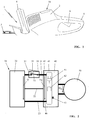
- Fig. 1 is a portable, hand-held implement 1 shown, which is shown in the embodiment as a hedge trimmer.
- the implement 1 is an electrical working device and is driven by a battery 10, which in the housing 2 of the Implement is inserted.
- the illustrated implement 1 has a tool 3, which by an electric motor 50 (FIG. Fig. 2 ) is driven.
- the implement 1 is formed with a front handle 4 and a rear handle 5, wherein in the embodiment in the rear handle 5, an actuator 6 for a power switch 30 (FIG. Fig. 2 ) is provided.
- the working device 1 can also be designed as a battery-operated blower, battery-operated brushcutter, battery-operated hedge trimmer or the like. Battery-powered working device.
- the battery 10 forms a voltage source 20 for the implement 1.
- the voltage source 20 provides a supply voltage U available, which is connected via the operation switch 30 to a drive circuit 40.
- the operating switch 30 is designed as a microswitch and comprises a switching lever 31, which acts on an actuating pin 32.
- the actuator 6 of the implement 1 attacks.
- the shift lever 31 is moved and designed as a make contact 33 is closed.
- the contact 33 is closed, so that the supply voltage U of the voltage source 20 via the connecting lines 21, 23 applied to the input terminals 45, 46 of the drive circuit 40 as an input voltage U E.
- this is further connected via at least one data line 22 to the drive circuit 40.
- the operating switch 30 is provided in the illustrated embodiment in the connecting line 21, which preferably forms the positive pole of the voltage source 20.
- a monitoring device 41 For monitoring the course of the input voltage U E , a monitoring device 41 is provided, to which the input voltage U E is supplied.
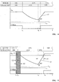
- the monitoring device 41 monitors a gradient dU / dt of the voltage rise 15 of the input voltage U E , such. In Fig. 4 played.
- the determined gradient dU / dt of the voltage increase 15 of the input voltage U E is compared with a predetermined limit value.
- Exceeds the determined gradient dU / dt the predetermined limit the operation switch 30 and the contact 33 of the operation switch 30 is detected as closed and reported this via a control line 43 of the drive circuit 40 so that it takes the electric motor 50 in operation.
- the monitoring device 41 is designed as part of the drive circuit 40.
- the monitoring device 41 comprises a timer 42, which specifies, for example, a pause time PZ. Only after the pause time PZ has elapsed is the gradient dU / dt of the voltage rise 15 of the input voltage U E evaluated, as in FIG FIG. 5 shown. This is particularly useful when switching off the electric motor 50 due to an error or overload.
- the monitoring device 41 may be provided with a comparison device 44, which compares the voltage applied to the input terminals 45, 46 input voltage U E with a predetermined voltage value U I , U S and / or U U , as described in detail below.
- the supply voltage U is greater than the operating voltage U B supplied to the electric motor 50 via the drive circuit 40.
- the drive circuit 40 varies the operating voltage U B of the electric motor 50 and adapts them to the permissible values, for. B. by a pulse width modulation.
- the circuit arrangement according to the invention Fig. 2 serves to detect the switching position of the operating switch 30 for commissioning of the electric motor 50th Der Electric motor 50 is connected via the drive circuit 40 to the voltage source 20, wherein the supply voltage U of the voltage source is connected as an input voltage U E to the drive circuit 40.
- a closed operation switch 30 is detected when the gradient dU / dt of a voltage increase 15 of the input voltage U E is above a predetermined limit.
- the input voltage U E of the drive circuit 40 monitors.
- the state of the operation switch 30 is in Fig. 4 in a bar above the diagram.
- the input voltage U E drops as the supply voltage U is disconnected from the input terminals 45/46.
- Fig. 4 it is assumed that the input voltage U E does not drop below a starting voltage U S or an initial voltage U I.
- the operation switch 30 at time t 3 again, the input voltage U E will increase.
- the electric motor 50 is switched on at the time t 4 .
- the operating switch 30 or its contact 33 have been detected as closed via the gradient dU / dt and the electric motor 50 is correctly put back into operation, which ensures a faster restart of the electric motor 50.
- the monitoring of the gradient dU / dt of the voltage rise 15 can already be done with the switching off of the operating switch 30, so start immediately. A negative gradient dU / dt of the voltage drop is ignored. Only a positive gradient dU / dt of the voltage increase 15 is compared with the predetermined limit value. Only if a positive gradient dU / dt is detected, this is an indicator of the switching state of the operating switch.
- a shutdown of the electric motor 50 is shown under power.
- the electric motor 50 can be switched off via a safety circuit at an excessive current consumption due to blocking of the tool 3 of the implement 1.
- time t 1 takes place after switching off the electric motor 50 by the safety circuit electrochemical recovery of the battery 10, resulting in a voltage increase 12. Only with the switching off of the operating switch 30 at the time t 2 , the input voltage U E falls according to the characteristic curve shown.
- a positive gradient dU / dt of the voltage rise 12 does not lead to an erroneous detection of the switching state of the operating switch 30, it is provided that after the switching off of the electric motor 50 by the safety circuit within a pause time PZ the gradient dU / dt of a voltage rise 15 is not evaluated or evaluated is not determined.
- the pause time PZ is selected so that it is greater than the recovery time EZ of the battery 10. The beginning of the search for a gradient dU / dt of the voltage rise 15 takes place after the pause time PZ has elapsed and the starting voltage Us has been exceeded, which in the example Fig. 5 is satisfied.
- the electric motor 50 is put into operation. It is provided that the exceeding of the determined gradient dU / dt of the voltage rise 15 is above the predetermined limit value and the exceeding of the predetermined initial voltage Ui within a predetermined period .DELTA.T. It has proven to be expedient if the period ⁇ T extends over a period of 80 to 200 milliseconds. Advantageously, the period ⁇ T is 100 milliseconds.
- a leakage of the electric motor 50 after turning off the operation switch 30 is shown.
- the input voltage U E after opening the operation switch 30 at time t 1 falls below an undervoltage Uu. If the user switches on the operating switch 30 again at time t 3 , the input voltage U E increases again until initially the undervoltage Uu is exceeded and following a starting voltage Us for restarting the electric motor 50 is exceeded.
- the monitoring according to the invention of the input voltage U E of the drive circuit 40 with respect to the gradient dU / dt of the voltage increase 15 takes place only after this time t ' 3. According to the representation of the voltage curve in FIG Fig.
- a gradient dU / dt of the voltage rise 15 which is greater than a predefined limit value, must first be determined. Furthermore, the condition must be met that the initial voltage U I exceeded before a restart of the electric motor 50 at time t 4 is.
- the gradient dU / dt of the voltage increase 15 is to be determined from the beginning of the exceeding of the starting voltage U S until the initial voltage U I is exceeded. As soon as the gradient of the gradient dU / dt over a given limit is detected, we cached it. If no gradient dU / dt of the voltage rise 15 is detected during this period t 3 to t 4 , which exceeds the predetermined limit value, the electric motor 50 is not put into operation.
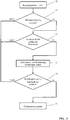
- FIG. 3 the sequence of an embodiment of the method according to the invention is reproduced.
- Field 70 indicates that the operating switch 30 - after a power off - is turned on again (ON).
- a first field 71 is queried whether the input voltage U E has reached the starting voltage Us for a restart of the electric motor 50. This is accordingly in Fig. 6 shown.
- the gradient dU / dt of the voltage rise 15 of the input voltage U E is determined and it is checked whether it is greater than a predefined limit value (field 72). If this is the case, in the field 73, the charge of a predetermined period .DELTA.T, within which the detection of the switching signal to turn on the electric motor 50 must be.
Description
Die Erfindung betrifft ein Verfahren sowie eine Vorrichtung zur Erkennung der Schaltstellung eines Betriebsschalters zur Inbetriebnahme eines Elektromotors.The invention relates to a method and a device for detecting the switching position of an operating switch for starting an electric motor.
Es sind Verfahren bekannt, mit denen der Elektromotor über eine Ansteuerschaltung in Betrieb genommen wird. Hierzu ist der Elektromotor über eine Ansteuerschaltung mit einer Spannungsquelle verbunden, wobei der Betriebsschalter zwischen der Ansteuerschaltung und der Spannungsquelle angeordnet ist. Der Betriebsschalter schaltet die Versorgungsspannung auf die Ansteuerschaltung, die daraufhin den angeschlossenen Elektromotor in Betrieb nimmt.Methods are known with which the electric motor is put into operation via a drive circuit. For this purpose, the electric motor is connected via a drive circuit to a voltage source, wherein the operating switch is arranged between the drive circuit and the voltage source. The operating switch switches the supply voltage to the drive circuit, which then takes the connected electric motor in operation.
Wird der Betriebsschalter geöffnet, läuft der Elektromotor aus. Während des Motorauslaufs liegt aufgrund der generatorischen Motorspannung des auslaufenden Elektromotors an der Ansteuerschaltung weiter Spannung an. Auch nach dem Stillstand des Elektromotors wird aufgrund der bestehenden Kapazitäten der Elektronik für weitere 1-2 Sekunden Spannung an der Ansteuerungselektronik anliegen. Erst nach Unterschreiten einer minimalen Versorgungsspannung von z. B. 5 V geht die Elektronik in einen Zustand über, aus dem sie nur über ein Reset wieder in Betrieb gehen kann, sobald erneut eine ausreichende Versorgungsspannung an der Elektronik anliegt.When the operation switch is opened, the electric motor stops. During the engine run-out voltage is due to the regenerative motor voltage of the expiring electric motor to the drive circuit on. Even after the stoppage of the electric motor is due to the existing capacity of the electronics for another 1-2 seconds voltage applied to the control electronics. Only after falling below a minimum supply voltage of z. B. 5 V, the electronics go into a state from which they can go back into operation only via a reset, as soon as again a sufficient supply voltage applied to the electronics.
Um einen störungssicheren Betrieb des Elektromotors zu gewährleisten, muss die Elektronik der Ansteuerschaltung den Zustand des Betriebsschalters kennen. Da die an der Ansteuerspannung anliegende Spannung aufgrund der generatorischen Motorspannung beim Auslaufen des Elektromotors keine eindeutige Erkennung eines geschlossenen Betriebsschalters gewährleistet, wird meist ein zusätzlicher Kontakt im Betriebsschalter genutzt. Über diesen zusätzlichen Kontakt erhält die Ansteuerschaltung die Information über den Schaltzustand des Betriebsschalters.
Zum Einschalten eines Elektromotors über eine Ansteuerschaltung sind regelmäßig Betriebsschalter mit einem zusätzlichen Kontakt für die Erkennung des Schaltzustands des Betriebsschalters notwendig, die konstruktiv aufwendig und daher kostenintensiv sind. Fällt der zusätzliche Kontakt für die Erkennung des Schaltzustands des Betriebsschalters aus, ist ein ordnungsgemäßer Betrieb des Elektromotors nicht gewährleistet.To ensure trouble-free operation of the electric motor, the electronics of the drive circuit must know the state of the operating switch. Since the voltage applied to the drive voltage due to the regenerative motor voltage at the expiration of the electric motor ensures no clear detection of a closed operation switch, usually an additional contact in the operation switch is used. About this additional contact, the drive circuit receives the information about the switching state of the operating switch.
For switching on an electric motor via a drive circuit operating switch with an additional contact for detecting the switching state of the operating switch are regularly necessary, which are structurally complex and therefore expensive. If the additional contact for the detection of the switching state of the operating switch fails, a proper operation of the electric motor is not guaranteed.
Dokument
Der Erfindung liegt die Aufgabe zugrunde, den Betriebsschalter zur Inbetriebnahme eines Elektromotors über eine Ansteuerschaltung einfacher und damit kostengünstiger auszubilden, dennoch aber in jedem Betriebszustand einen sicheren Betrieb des Elektromotors über die Ansteuerschaltung zu gewährleisten.
Die Aufgabe wird mit einem Verfahren nach dem Anspruch 1 gelöst.
Eine Vorrichtung zur Erkennung der Schaltstellung eines Betriebsschalters zur Inbetriebnahme eines Elektromotors ist im Anspruch 10 wiedergegeben.
Gemäß dem erfindungsgemäßen Verfahren wird nach einem Abschalten des Elektromotors die Eingangsspannung der Ansteuerschaltung überwacht. Dies ist grundsätzlich auch nach dem Ausschalten des Betriebsschalters für eine begrenzte Zeitspanne möglich, da aufgrund der generatorischen Motorspannung und von in der Elektronik verbauten Kondensatoren und/oder Spulen die Ansteuerschaltung für einen begrenzten Zeitraum weiter funktionsfähig bleibt.The invention is based on the object, the operating switch for commissioning an electric motor via a drive circuit simpler and thus cheaper form, but still to ensure safe operation of the electric motor via the drive circuit in any operating condition.
The object is achieved by a method according to
A device for detecting the switching position of an operating switch for starting an electric motor is shown in
According to the inventive method, the input voltage of the drive circuit is monitored after switching off the electric motor. This is basically possible even after turning off the power switch for a limited period of time, because due to the regenerative motor voltage and built-in electronics capacitors and / or coils, the drive circuit for a limited period of time remains functional.
Gemäß der Erfindung wird nach dem Abschalten des Elektromotors und dem Wiedereinschalten des Betriebsschalters der Gradient eines Spannungsanstiegs der an der Ansteuerschaltung anliegenden Eingangsspannung ermittelt. Dieser ermittelte Gradient des Spannungsanstiegs wird mit einem vorgegebenen Grenzwert verglichen. Dabei kann bei Überschreiten des vorgegebenen Grenzwertes darauf geschlossen werden, dass der Betriebsschalter geschlossen ist. Wird der Betriebsschalter als geschlossen erkannt, wird der Elektromotor über die Ansteuerschaltung erneut in Betrieb genommen, so dass ein rasches und sicheres Wiederanlaufen des Elektromotors erzielt ist.According to the invention, after the switching off of the electric motor and the reconnection of the operating switch, the gradient of a voltage increase of the input voltage applied to the drive circuit is determined. This determined gradient of the voltage increase is compared with a predetermined limit. It can be concluded when the predetermined limit is exceeded that the operating switch is closed. If the operating switch is detected as closed, the electric motor is put into operation again via the drive circuit, so that a rapid and safe restart of the electric motor is achieved.
Nach der Erfindung ist der Gradient des Spannungsanstiegs der Indikator für den Schaltzustand des Betriebsschalters. Dadurch kann auf einen zusätzlichen Schaltkontakt zur Erkennung des Schaltzustandes des Betriebsschalters verzichtet werden, was die Konstruktion des Betriebsschalters vereinfacht. Ferner entfällt eine ansonsten notwendige Verdrahtung des zusätzlichen Schaltkontakts zur Ansteuerschaltung. Der Gradient des Spannungsanstiegs wird als verlässliche Information über den Schaltzustand des Betriebsschalters genutzt.According to the invention, the gradient of the voltage rise is the indicator for the switching state of the operating switch. This can be dispensed with an additional switching contact for detecting the switching state of the operating switch, which simplifies the construction of the operating switch. Furthermore, an otherwise necessary wiring of the additional switching contact to the drive circuit is eliminated. The gradient of the voltage rise is used as reliable information about the switching state of the operating switch.
Eine erneute Inbetriebnahme des Elektromotors erfolgt regelmäßig nach einem Öffnen des Betriebsschalters. Nach dem Öffnen des Betriebsschalters wird die Eingangsspannung an der Ansteuerschaltung abfallen. Die Ansteuerschaltung ist aber nicht sofort stromlos, sondern bleibt auch bei abfallender Eingangsspannung für einen begrenzten Zeitraum funktionsfähig. Nach einem erneuten Betätigen des Betriebsschalters (Betriebsschalter geschlossen) wird die Eingangsspannung der Ansteuerschaltung ansteigen. Ist der Gradient des Spannungsanstiegs größer als ein vorgegebener Grenzwert, erkennt die Ansteuerschaltung den geschlossenen Betriebsschalter anhand des ermittelten Gradienten und kann den Elektromotor durch entsprechende Ansteuerung sofort wieder in Betrieb nehmen.A re-commissioning of the electric motor is done regularly after opening the operating switch. After opening the operating switch, the input voltage at the drive circuit will drop. However, the drive circuit is not immediately de-energized, but remains functional even with falling input voltage for a limited period. After a renewed actuation of the operating switch (operating switch closed), the input voltage of the drive circuit will increase. If the gradient of the voltage increase is greater than a predetermined limit value, the drive circuit recognizes the closed operating switch on the basis of the determined gradient and can immediately restart the electric motor by appropriate control.
Sinkt nach einem Abschalten des Elektromotors und einem Öffnen des Betriebsschalters die Eingangsspannung an der Ansteuerschaltung unter einen vorgegebenen Grenzwert, so wird zum Wiedereinschalten des Elektromotors gefordert, dass ein erneutes Wiedereinschalten erst bei Spannungswerten der Eingangsspannung erfolgt, die oberhalb des vorgegebenen Grenzwertes liegen. Der Elektromotor wird erst dann in Betrieb genommen, wenn ein Gradient des Spannungsanstiegs der Eingangsspannung oberhalb eines vorgegebenen Grenzwertes liegt und die Eingangsspannung der Ansteuerschaltung oberhalb eines vorgegebenen Grenzwertes liegt.Decreases after switching off the electric motor and opening the operating switch, the input voltage to the drive circuit below a predetermined limit, it is required to restart the electric motor that a renewed reconnection takes place only at voltage values of the input voltage, which are above the predetermined limit. The electric motor is only put into operation when a gradient of the voltage increase of the input voltage is above a predetermined limit value and the input voltage of the drive circuit is above a predetermined limit value.
Es hat sich als zweckmäßig erwiesen, wenn das Überschreiten des ermittelten Gradienten des Spannungsanstiegs über den vorgegebenen Grenzwert und das Überschreiten des vorgegebenen Spannungswertes innerhalb eines vorgegebenen Zeitfensters liegen. Nur wenn diese beiden Bedingungen innerhalb des Zeitfensters erfüllt werden, wird der Elektromotor in Betrieb genommen.It has proven to be expedient if the exceeding of the ascertained gradient of the voltage rise above the predetermined limit value and the exceeding of the predefined voltage value are within a predetermined time window. Only when these two conditions are met within the time window, the electric motor is put into operation.
Das Zeitfenster erstreckt sich zweckmäßig über einen Zeitraum von 80 bis 200 Millisekunden. Vorteilhaft ist das Zeitfenster mit 100 Millisekunden bemessen.The time window expediently extends over a period of 80 to 200 milliseconds. Advantageously, the time window is rated at 100 milliseconds.
Wird innerhalb des Zeitfensters nur eine der beiden genannten Bedingungen erfüllt, wird die Ansteuerschaltung resettet.If only one of the two conditions mentioned is fulfilled within the time window, the drive circuit is reset.
Vorteilhaft ist vorgesehen, dass der Spannungsanstieg der Eingangsspannung erst nach Ablauf einer Pausenzeit nach dem Abschalten des Elektromotors ermittelt wird. Dadurch wird gewährleistet, dass ein Spannungsanstieg aufgrund der elektrochemischen Erholung des Akkus nicht zu einem Wiederanlaufen des Elektromotors führen kann. Zweckmäßig ist vorgesehen, dass die Pausenzeit größer als die Erholzeit des Akkus gewählt wird.Advantageously, it is provided that the voltage increase of the input voltage is determined only after a pause time has elapsed after switching off the electric motor. This ensures that a voltage increase due to the electrochemical recovery of the battery can not lead to a restart of the electric motor. Appropriately, it is provided that the pause time is greater than the recovery time of the battery is selected.
Die Auslegung der elektrischen Schaltung zur Durchführung des erfindungsgemäßen Verfahrens ist so vorgesehen, dass nach dem Öffnen des Betriebsschalters die Eingangsspannung der Ansteuerschaltung über einen Zeitraum von 1 bis 4 Sekunden unter einen vorgegebenen Grenzwert abfällt.The design of the electrical circuit for carrying out the method according to the invention is provided so that after opening the operating switch, the input voltage of the drive circuit drops below a predetermined limit over a period of 1 to 4 seconds.
Die erfindungsgemäße Vorrichtung zur Erkennung der Schaltstellung eines Betriebsschalters zur Inbetriebnahme eines Elektromotors ist derart ausgebildet, dass der Elektromotor über die Ansteuerschaltung mit einer Spannungsquelle verbunden ist. Der Betriebsschalter ist zwischen der Ansteuerschaltung und der Spannungsquelle angeordnet und schaltet die Versorgungsspannung der Spannungsquelle als Eingangsspannung auf die Ansteuerschaltung. Es ist eine Überwachungsvorrichtung vorgesehen, an der die Eingangsspannung der Ansteuerschaltung anliegt. Die Überwachungsvorrichtung überwacht einen Gradienten des Spannungsanstiegs der Eingangsspannung und vergleicht den ermittelten Gradienten mit einem vorgegebenen Grenzwert. Wird der vorgegebene Grenzwert überschritten, ist dies der Indikator für einen geschlossenen Betriebsschalter. Bei Überschreiten des vorgegebenen Grenzwertes kann somit der Betriebsschalter als geschlossen erkannt werden. Die Überwachungsvorrichtung wird bei Erkennen eines geschlossenen Betriebsschalters ein Startsignal an die Ansteuerschaltung übermitteln, worauf diese den Elektromotor erneut in Betrieb nimmt.The inventive device for detecting the switching position of an operating switch for starting an electric motor is designed such that the electric motor is connected via the drive circuit with a voltage source. The operating switch is arranged between the drive circuit and the voltage source and switches the supply voltage of the voltage source as an input voltage to the drive circuit. A monitoring device is provided, to which the input voltage of the drive circuit is applied. The monitoring device monitors a gradient of the voltage rise of the input voltage and compares the determined gradient with a predetermined limit value. If the predetermined limit is exceeded, this is the indicator for a closed operation switch. When the predetermined limit value is exceeded, the operating switch can thus be recognized as closed. The monitoring device will transmit a start signal to the drive circuit upon detection of a closed operation switch, whereupon this takes the electric motor again in operation.
Um die elektrochemische Regeneration eines Akkus nach Abschalten der Last auszublenden, ist vorgesehen, die Überwachungseinrichtung mit einem Zeitglied auszubilden und den Gradienten des Spannungsanstiegs erst dann zu erfassen, wenn das Zeitglied abgelaufen ist.To hide the electrochemical regeneration of a battery after switching off the load, it is provided to form the monitoring device with a timer and to detect the gradient of the voltage increase only when the timer has expired.
Neben der Ermittlung und Überwachung des Gradienten des Spannungsanstiegs kann die Überwachungsvorrichtung eine Vergleichseinrichtung aufweisen, die die Eingangsspannung der Ansteuerschaltung mit einem vorgegebenen Spannungswert vergleicht. So ist die Möglichkeit gegeben, neben dem Gradienten des Spannungsanstiegs weitere Bedingungen abzufragen, die vor einer Wiederinbetriebnahme des Elektromotors erfüllt sein müssen.In addition to the determination and monitoring of the gradient of the voltage rise, the monitoring device may have a comparison device which compares the input voltage of the drive circuit with a predetermined voltage value. So there is the possibility, in addition to the gradient of the voltage increase more Querying conditions that must be met before restarting the electric motor.
Die Spannungsquelle ist zweckmäßig ein Akku, wobei die Akkuspannung größer als die Betriebsspannung des Elektromotors vorgesehen sein kann.The voltage source is expediently a rechargeable battery, it being possible for the rechargeable battery voltage to be greater than the operating voltage of the electric motor.
Weitere Merkmale der Erfindung ergeben sich aus den weiteren Ansprüchen, der Beschreibung und der Zeichnung, in der nachfolgend im Einzelnen beschriebene Ausführungsbeispiele der Erfindung dargestellt sind. Es zeigen:
- Fig. 1
- in schematischer Seitenansicht ein tragbares, elektrisches Arbeitsgerät mit einem Akku,
- Fig. 2
- eine schematische Darstellung eines Schaltplans zum Betrieb eines Elektromotors,
- Fig. 3
- ein Ablaufdiagramm zur Inbetriebnahme des Elektromotors,
- Fig. 4
- in schematischer Darstellung den Spannungsverlauf einer Eingangsspannung einer Ansteuerschaltung für den Elektromotor,
- Fig. 5
- eine schematische Darstellung des Spannungsverlaufs gemäß
Fig. 4 nach einer Abschaltung des Elektromotors unter Strom, - Fig. 6
- eine schematische Darstellung des Spannungsverlaufs der Eingangsspannung bei Auftreten einer Unterspannung.
- Fig. 1
- a schematic side view of a portable, electrical implement with a battery,
- Fig. 2
- a schematic representation of a circuit diagram for operating an electric motor,
- Fig. 3
- a flow chart for commissioning the electric motor,
- Fig. 4
- a schematic representation of the voltage curve of an input voltage of a drive circuit for the electric motor,
- Fig. 5
- a schematic representation of the voltage curve according to
Fig. 4 after a shutdown of the electric motor under power, - Fig. 6
- a schematic representation of the voltage waveform of the input voltage when an undervoltage occurs.
In
Das Arbeitsgerät 1 ist mit einem vorderen Handgriff 4 und einem hinteren Handgriff 5 ausgebildet, wobei im Ausführungsbeispiel im hinteren Handgriff 5 ein Betätigungsglied 6 für einen Betriebsschalter 30 (
Das Arbeitsgerät 1 kann auch als akkubetriebenes Blasgerät, akkubetriebener Freischneider, akkubetriebene Heckenschere oder dgl. akkubetriebenes Arbeitsgerät ausgeführt sein.The working
Wie
Im gezeigten Ausführungsbeispiel ist der Betriebsschalter 30 als Mikroschalter ausgebildet und umfasst einen Schalthebel 31, der auf einen Betätigungsstift 32 wirkt. An dem Schalthebel 31 greift das Betätigungsglied 6 des Arbeitsgerätes 1 an. Durch Niederdrücken des Betätigungsgliedes 6 wird der Schalthebel 31 bewegt und der als Schließer gestaltete Kontakt 33 geschlossen.In the exemplary embodiment shown, the operating
Bei geschlossenem Betriebsschalter 30 ist der Kontakt 33 geschlossen, so dass die Versorgungsspannung U der Spannungsquelle 20 über die Verbindungsleitungen 21, 23 an den Eingangsklemmen 45, 46 der Ansteuerschaltung 40 als Eingangsspannung UE anliegt. Zur Kommunikation des Akkus 20 mit der Ansteuerschaltung 40 ist dieser ferner über zumindest eine Datenleitung 22 mit der Ansteuerschaltung 40 verbunden. Der Betriebsschalter 30 ist im gezeigten Ausführungsbeispiel in der Verbindungsleitung 21 vorgesehen, die vorzugsweise den Pluspol der Spannungsquelle 20 bildet.When the operating
Zur Überwachung des Verlaufs der Eingangsspannung UE ist eine Überwachungsvorrichtung 41 vorgesehen, der die Eingangsspannung UE zugeführt ist. Die Überwachungsvorrichtung 41 überwacht einen Gradienten dU/dt des Spannungsanstiegs 15 der Eingangsspannung UE, wie z. B. in
Im Ausführungsbeispiel nach
In Ergänzung kann die Überwachungsvorrichtung 41 mit einer Vergleichseinrichtung 44 versehen sein, die die an den Eingangsklemmen 45, 46 anliegende Eingangsspannung UE mit einem vorgegebenen Spannungswert UI, US und/oder UU vergleicht, wie es nachstehend noch im Einzelnen beschrieben ist.In addition, the
Im Ausführungsbeispiel nach
Die erfindungsgemäße Schaltungsanordnung gemäß
Liegt - wie in
Öffnet der Benutzer den Betriebsschalter 30 im Zeitpunkt t1 so fällt - da die Versorgungsspannung U von den Eingangsklemmen 45/46 getrennt ist - die Eingangsspannung UE ab. In
Die Überwachung des Gradienten dU/dt des Spannungsanstiegs 15 kann bereits mit dem Ausschalten des Betriebsschalters 30 erfolgen, also sofort starten. Ein negativer Gradient dU/dt des Spannungsabfalls wird ignoriert. Nur ein positiver Gradient dU/dt des Spannungsanstiegs 15 wird mit dem vorgegebenen Grenzwert verglichen. Nur wenn ein positiver Gradient dU/dt festgestellt wird, ist dies ein Indikator für den Schaltzustand des Betriebsschalters.The monitoring of the gradient dU / dt of the voltage rise 15 can already be done with the switching off of the operating
Im Ausführungsbeispiel nach
Wird nach einem Öffnen des Betriebsschalters 30 der Betriebsschalter im Zeitpunkt t3 erneut betätigt, erfolgt ab diesem Zeitpunkt t3 ein Spannungsanstieg 15. Wird festgestellt, dass der nach dem Einschalten des Betriebsschalters 30 ermittelte Gradient dU/dt des Spannungsanstiegs 15 den vorgegebenen Grenzwert überschreitet, ist ein geschlossener Betriebsschalter erkannt und eine erste Bedingung für das Wiedereinschalten des Elektromotors 50 erfüllt. Die Erfüllung dieser ersten Bedingung für das Einschalten des Elektromotors 50 (Erkennung des geschlossenen Betriebsschalters 30 durch Überschreiten des vorgegebenen Grenzwerts des Spannungsanstiegs dU/dt) wird für einen bestimmten Zeitraum ΔT in einem Zwischenspeicher festgehalten. Die in
Wird nach Ablauf des Zeitraums ΔT zumindest eine der beiden Bedingungen (Überschreiten des Grenzwertes des Gradienten dU/dt des Spannungsanstiegs 15 und/oder das Überschreiten des vorgegebenen Initialwertes UI) nicht festgestellt, erfolgt kein Wiedereinschalten des Elektromotors 50.If at least one of the two conditions (exceeding the limit value of the gradient dU / dt of the voltage rise 15 and / or the exceeding of the predetermined initial value U I ) is not established after expiration of the time interval ΔT, the
In
In
Ist dieses der Fall, liegt also die Eingangsspannung UE oberhalb einer vorgegebenen Startspannung Us, wird der Gradient dU/dt des Spannungsanstiegs 15 der Eingangsspannung UE ermittelt und überprüft, ob dieser größer als ein vorgegebener Grenzwert ist (Feld 72). Trifft dieses zu, erfolgt im Feld 73 die Ladung eines vorgegebenen Zeitraums ΔT, innerhalb dem die Erkennung des Schaltsignals zum Einschalten des Elektromotors 50 liegen muss.If this is the case, ie if the input voltage U E is above a predetermined starting voltage Us, the gradient dU / dt of the voltage rise 15 of the input voltage U E is determined and it is checked whether it is greater than a predefined limit value (field 72). If this is the case, in the
Danach erfolgt im Feld 74 die Abfrage, ob die Initialspannung UI innerhalb des Zeitfenster ΔT erreicht wurde. Ist dieses der Fall, wird im Feld 75 der Elektromotor 50 gestartet. Treffen die in den Feldern 72 und 74 genannten Bedingungen nicht zu, wird über den NEIN-Zweig zurück auf das Feld 71 verzweigt. Wird z. B. nach der Erkennung des Gradienten dU/dt die Initialspannung Ui innerhalb des Zeitfenster ΔT nicht erreicht, wird über den NEIN-Pfad zum Eingang des Feldes 71 zurück verzweigt.This is followed in the
Claims (14)
- Method for detecting the switching position of an operating switch (30) for starting an electric motor (50), wherein the electric motor (50) is connected to a voltage source (20) via a drive circuit (40) and the operating switch (30), which switches the supply voltage (U) of the voltage source (20) as an input voltage (UE) onto the drive circuit (40), is located between the drive circuit (40) and the voltage source (20),
characterised in thata) after a switch-off of the electric motor (50), the input voltage (UE) of the drive circuit (40) is monitored,b) a gradient (dU/dt) of a voltage increase (15) of the input voltage (UE) is determined,c) the determined gradient (dU/dt) of the voltage increase (15) of the input voltage (UE) is compared to a preset limit value, andd) if the preset limit value is exceeded, the operating switch (30) is deemed closed and the electric motor (50) can be restarted via the drive circuit (40). - Method according to claim 1,
characterised in that the electric motor (50) is restarted after an opening of the operating switch (30), - Method according to claim 1 or 2,
characterised in that the electric motor (50) is started via the drive circuit (40) only after a preset voltage value (Ui) has been exceeded. - Method according to claim 3,
characterised in that the exceeding of the determined gradient (dU/dt) of the voltage increase (15) above the preset limit value and the exceeding of the preset voltage value (Ui) lie within a preset time window (ΔT). - Method according to claim 4,
characterised in that the time window (ΔT) extends over a period of 80 to 200 milliseconds, being 100 milliseconds in particular. - Method according to claim 5,
characterised in that the drive circuit (40) is reset on expiry of the time window (ΔT). - Method according to claim 1,
characterised in that the voltage increase (15) of the input voltage (U) is only determined on expiry of a pause time (PZ) after a switch-off of the electric motor (50). - Method according to claim 7,
characterised in that the voltage source (20) is a battery (10) and the pause time (PZ) is longer than the recovery time of the battery (10). - Method according to claim 1,
characterised in that following the opening of the operating switch (30), the input voltage (UE) of the drive circuit (40) falls below a preset limit value (Us), in particular to zero, over a period of 1 to 4 seconds. - Device for detecting the switching position of an operating switch (30) for starting an electric motor (50), wherein the electric motor (50) is connected to a voltage source (20) via a drive circuit (40) and the operating switch (30) is located between the drive circuit (40) and the voltage source (20), wherein the operating switch (30) switches the supply voltage (U) of the voltage source (20) as an input voltage (UE) onto the drive circuit (40),
characterised in that a monitoring device (41), to which the input voltage (UE) of the drive circuit (40) is applied, is provided, in that the monitoring device (41) monitors a gradient (dU/dt) of the voltage increase (15) of the input voltage (UE) and the monitoring device (41) compares the determined gradient (dU/dt) to a preset limit value and, if the preset limit value is exceeded, the operating switch (30) is deemed closed and the drive circuit (40) receives a start signal via at least one control line (43) for restarting the electric motor (50) via the drive circuit (40). - Device according to claim 10,
characterised in that the monitoring device (41) comprises a timing element (42) and the gradient (dU/dt) of the voltage increase (15) of the input voltage (UE) is only determined on expiry of the timing element (42). - Device according to claim 10,
characterised in that the monitoring device (41) comprises a comparison device (44), which compares the input voltage (UE) to a preset voltage value (UI, US, UU). - Device according to claim 10,
characterised in that the voltage source (20) is a battery (10). - Device according to claim 13,
characterised in that the battery voltage (U) is higher than the operating voltage (UB) of the electric motor (50).
Applications Claiming Priority (1)
| Application Number | Priority Date | Filing Date | Title |
|---|---|---|---|
| DE102016004525.6A DE102016004525A1 (en) | 2016-04-14 | 2016-04-14 | Method and device for detecting the switching position of an operating switch for starting up an electric motor |
Publications (2)
| Publication Number | Publication Date |
|---|---|
| EP3236483A1 EP3236483A1 (en) | 2017-10-25 |
| EP3236483B1 true EP3236483B1 (en) | 2019-02-13 |
Family
ID=58701357
Family Applications (1)
| Application Number | Title | Priority Date | Filing Date |
|---|---|---|---|
| EP17000628.2A Active EP3236483B1 (en) | 2016-04-14 | 2017-04-12 | Method and device for detecting the switching position of an operating switch for putting an electric motor into operation |
Country Status (4)
| Country | Link |
|---|---|
| US (1) | US10063165B2 (en) |
| EP (1) | EP3236483B1 (en) |
| CN (1) | CN107306028B (en) |
| DE (1) | DE102016004525A1 (en) |
Families Citing this family (1)
| Publication number | Priority date | Publication date | Assignee | Title |
|---|---|---|---|---|
| EP3790177A1 (en) | 2019-09-09 | 2021-03-10 | Andreas Stihl AG & Co. KG | Electric processing device and method for operating same |
Family Cites Families (10)
| Publication number | Priority date | Publication date | Assignee | Title |
|---|---|---|---|---|
| US6118238A (en) * | 1998-08-26 | 2000-09-12 | Satcon Technology Corporation | Motor starting apparatus for an engine driven generator |
| DE10322385B3 (en) * | 2003-05-17 | 2004-11-11 | Moeller Gmbh | Method and circuit arrangement for monitoring the function of an electronic-mechanical position switch |
| US8143749B2 (en) * | 2008-11-06 | 2012-03-27 | Qualcomm Incorporated | Dual current switch detection circuit with selective activation |
| US8334670B2 (en) * | 2010-03-25 | 2012-12-18 | GM Global Technology Operations LLC | Method and apparatus to monitor an electric motor control circuit |
| DE102011010224A1 (en) * | 2011-02-03 | 2012-08-09 | Festool Gmbh | Hand machine tool with a temperature-dependent sensor |
| US20130327552A1 (en) * | 2012-06-08 | 2013-12-12 | Black & Decker Inc. | Power tool having multiple operating modes |
| CN202931247U (en) * | 2012-10-19 | 2013-05-08 | 广州汽车集团股份有限公司 | Automobile AC generator voltage regulator |
| EP2804163B1 (en) * | 2013-05-17 | 2015-09-16 | Minimax GmbH & Co KG | Method and apparatus for detecting faults in control lines in hazard warning and control systems |
| JP6128037B2 (en) * | 2014-03-28 | 2017-05-17 | 日立工機株式会社 | Electric tool |
| CN106463955B (en) * | 2014-04-29 | 2020-01-21 | 三菱电机株式会社 | Power switching device and system using same |
-
2016
- 2016-04-14 DE DE102016004525.6A patent/DE102016004525A1/en not_active Withdrawn
-
2017
- 2017-04-12 EP EP17000628.2A patent/EP3236483B1/en active Active
- 2017-04-14 US US15/488,055 patent/US10063165B2/en active Active
- 2017-04-14 CN CN201710244087.0A patent/CN107306028B/en active Active
Non-Patent Citations (1)
| Title |
|---|
| None * |
Also Published As
| Publication number | Publication date |
|---|---|
| DE102016004525A1 (en) | 2017-10-19 |
| CN107306028A (en) | 2017-10-31 |
| US10063165B2 (en) | 2018-08-28 |
| US20170302198A1 (en) | 2017-10-19 |
| EP3236483A1 (en) | 2017-10-25 |
| CN107306028B (en) | 2020-04-07 |
Similar Documents
| Publication | Publication Date | Title |
|---|---|---|
| DE102006027828B4 (en) | Engine control device | |
| EP1901411B1 (en) | Method for actuating the motor of a battery driven tool | |
| EP2925556B1 (en) | Charging an electrical energy store on an electric vehicle at a socket with reduction of the charging current after failure and restoration of the power supply | |
| EP2609322B1 (en) | Method and device for operating a starter of a vehicle | |
| EP2509214B1 (en) | Method for initiating an electronic control circuit of an electric motor and circuit assembly for same | |
| EP3144111B1 (en) | Method for starting up a hand-held work machine with an electric motor | |
| DE102018102972A1 (en) | Power supply adapter and method for supplying electric power to an electric machine | |
| DE102015001394A1 (en) | Motorized device and protective method thereof | |
| EP3236483B1 (en) | Method and device for detecting the switching position of an operating switch for putting an electric motor into operation | |
| DE202006018837U1 (en) | Power tool with protection circuit | |
| DE112009005178B4 (en) | Pipe cutter | |
| DE102018127502B4 (en) | restart protection device | |
| DE102005054693B4 (en) | Control system for driving a gate or a door | |
| EP1994620B1 (en) | Protective device and method for monitoring the appliance temperature of an appliance | |
| EP0019885A1 (en) | Overload watching arrangement | |
| DE102007057630A1 (en) | Control device and method for starting an internal combustion engine | |
| WO2009103584A1 (en) | Method and device for operating a switching unit | |
| EP2229719B1 (en) | Circuit configuration for operating a household appliance | |
| DE102010055479A1 (en) | Smart FET controlling circuit for use in switching arrangement serving as electronic control unit in electronic system, has control circuit generating control signal that switches off switch during incorrect operation | |
| DE19951747C1 (en) | Electric motor operating circuit e.g. for electric handtool, has dual operating switch for reversing polarity of motor field winding for switching between drive and braking modes | |
| EP2546942A2 (en) | Resetting of an arc fault protection device | |
| EP1333346B1 (en) | Method and device for fault diagnosis in controlled electrical drives | |
| EP1312799A2 (en) | Starting device for internal combustion engines | |
| EP1760874A2 (en) | Control device for an electronic apparatus for home or garden | |
| DE10259732A1 (en) | Control circuit for a motor vehicle windscreen wiper direct current motor, has a switching element to which a pulse modulated control signal is applied to for continuous control of motor speed |
Legal Events
| Date | Code | Title | Description |
|---|---|---|---|
| PUAI | Public reference made under article 153(3) epc to a published international application that has entered the european phase |
Free format text: ORIGINAL CODE: 0009012 |
|
| STAA | Information on the status of an ep patent application or granted ep patent |
Free format text: STATUS: THE APPLICATION HAS BEEN PUBLISHED |
|
| AK | Designated contracting states |
Kind code of ref document: A1 Designated state(s): AL AT BE BG CH CY CZ DE DK EE ES FI FR GB GR HR HU IE IS IT LI LT LU LV MC MK MT NL NO PL PT RO RS SE SI SK SM TR |
|
| AX | Request for extension of the european patent |
Extension state: BA ME |
|
| RIN1 | Information on inventor provided before grant (corrected) |
Inventor name: GURR, KAY-STEFFEN Inventor name: LEUFEN, HEINRICH Inventor name: LIEBHARD, GERNOT Inventor name: KLOEKER, JENS Inventor name: SILLER, JOCHEN |
|
| STAA | Information on the status of an ep patent application or granted ep patent |
Free format text: STATUS: REQUEST FOR EXAMINATION WAS MADE |
|
| 17P | Request for examination filed |
Effective date: 20180411 |
|
| RBV | Designated contracting states (corrected) |
Designated state(s): AL AT BE BG CH CY CZ DE DK EE ES FI FR GB GR HR HU IE IS IT LI LT LU LV MC MK MT NL NO PL PT RO RS SE SI SK SM TR |
|
| GRAP | Despatch of communication of intention to grant a patent |
Free format text: ORIGINAL CODE: EPIDOSNIGR1 |
|
| STAA | Information on the status of an ep patent application or granted ep patent |
Free format text: STATUS: GRANT OF PATENT IS INTENDED |
|
| GRAJ | Information related to disapproval of communication of intention to grant by the applicant or resumption of examination proceedings by the epo deleted |
Free format text: ORIGINAL CODE: EPIDOSDIGR1 |
|
| GRAP | Despatch of communication of intention to grant a patent |
Free format text: ORIGINAL CODE: EPIDOSNIGR1 |
|
| INTG | Intention to grant announced |
Effective date: 20180711 |
|
| GRAJ | Information related to disapproval of communication of intention to grant by the applicant or resumption of examination proceedings by the epo deleted |
Free format text: ORIGINAL CODE: EPIDOSDIGR1 |
|
| STAA | Information on the status of an ep patent application or granted ep patent |
Free format text: STATUS: REQUEST FOR EXAMINATION WAS MADE |
|
| INTG | Intention to grant announced |
Effective date: 20180802 |
|
| GRAP | Despatch of communication of intention to grant a patent |
Free format text: ORIGINAL CODE: EPIDOSNIGR1 |
|
| STAA | Information on the status of an ep patent application or granted ep patent |
Free format text: STATUS: GRANT OF PATENT IS INTENDED |
|
| INTC | Intention to grant announced (deleted) | ||
| INTG | Intention to grant announced |
Effective date: 20180905 |
|
| GRAS | Grant fee paid |
Free format text: ORIGINAL CODE: EPIDOSNIGR3 |
|
| GRAA | (expected) grant |
Free format text: ORIGINAL CODE: 0009210 |
|
| STAA | Information on the status of an ep patent application or granted ep patent |
Free format text: STATUS: THE PATENT HAS BEEN GRANTED |
|
| AK | Designated contracting states |
Kind code of ref document: B1 Designated state(s): AL AT BE BG CH CY CZ DE DK EE ES FI FR GB GR HR HU IE IS IT LI LT LU LV MC MK MT NL NO PL PT RO RS SE SI SK SM TR |
|
| REG | Reference to a national code |
Ref country code: GB Ref legal event code: FG4D Free format text: NOT ENGLISH |
|
| REG | Reference to a national code |
Ref country code: CH Ref legal event code: EP Ref country code: AT Ref legal event code: REF Ref document number: 1096676 Country of ref document: AT Kind code of ref document: T Effective date: 20190215 |
|
| REG | Reference to a national code |
Ref country code: IE Ref legal event code: FG4D Free format text: LANGUAGE OF EP DOCUMENT: GERMAN |
|
| REG | Reference to a national code |
Ref country code: DE Ref legal event code: R096 Ref document number: 502017000740 Country of ref document: DE |
|
| REG | Reference to a national code |
Ref country code: LT Ref legal event code: MG4D |
|
| REG | Reference to a national code |
Ref country code: NL Ref legal event code: MP Effective date: 20190213 |
|
| PG25 | Lapsed in a contracting state [announced via postgrant information from national office to epo] |
Ref country code: PT Free format text: LAPSE BECAUSE OF FAILURE TO SUBMIT A TRANSLATION OF THE DESCRIPTION OR TO PAY THE FEE WITHIN THE PRESCRIBED TIME-LIMIT Effective date: 20190613 Ref country code: SE Free format text: LAPSE BECAUSE OF FAILURE TO SUBMIT A TRANSLATION OF THE DESCRIPTION OR TO PAY THE FEE WITHIN THE PRESCRIBED TIME-LIMIT Effective date: 20190213 Ref country code: NL Free format text: LAPSE BECAUSE OF FAILURE TO SUBMIT A TRANSLATION OF THE DESCRIPTION OR TO PAY THE FEE WITHIN THE PRESCRIBED TIME-LIMIT Effective date: 20190213 Ref country code: LT Free format text: LAPSE BECAUSE OF FAILURE TO SUBMIT A TRANSLATION OF THE DESCRIPTION OR TO PAY THE FEE WITHIN THE PRESCRIBED TIME-LIMIT Effective date: 20190213 Ref country code: NO Free format text: LAPSE BECAUSE OF FAILURE TO SUBMIT A TRANSLATION OF THE DESCRIPTION OR TO PAY THE FEE WITHIN THE PRESCRIBED TIME-LIMIT Effective date: 20190513 Ref country code: FI Free format text: LAPSE BECAUSE OF FAILURE TO SUBMIT A TRANSLATION OF THE DESCRIPTION OR TO PAY THE FEE WITHIN THE PRESCRIBED TIME-LIMIT Effective date: 20190213 |
|
| PG25 | Lapsed in a contracting state [announced via postgrant information from national office to epo] |
Ref country code: BG Free format text: LAPSE BECAUSE OF FAILURE TO SUBMIT A TRANSLATION OF THE DESCRIPTION OR TO PAY THE FEE WITHIN THE PRESCRIBED TIME-LIMIT Effective date: 20190513 Ref country code: IS Free format text: LAPSE BECAUSE OF FAILURE TO SUBMIT A TRANSLATION OF THE DESCRIPTION OR TO PAY THE FEE WITHIN THE PRESCRIBED TIME-LIMIT Effective date: 20190613 Ref country code: RS Free format text: LAPSE BECAUSE OF FAILURE TO SUBMIT A TRANSLATION OF THE DESCRIPTION OR TO PAY THE FEE WITHIN THE PRESCRIBED TIME-LIMIT Effective date: 20190213 Ref country code: LV Free format text: LAPSE BECAUSE OF FAILURE TO SUBMIT A TRANSLATION OF THE DESCRIPTION OR TO PAY THE FEE WITHIN THE PRESCRIBED TIME-LIMIT Effective date: 20190213 Ref country code: GR Free format text: LAPSE BECAUSE OF FAILURE TO SUBMIT A TRANSLATION OF THE DESCRIPTION OR TO PAY THE FEE WITHIN THE PRESCRIBED TIME-LIMIT Effective date: 20190514 Ref country code: HR Free format text: LAPSE BECAUSE OF FAILURE TO SUBMIT A TRANSLATION OF THE DESCRIPTION OR TO PAY THE FEE WITHIN THE PRESCRIBED TIME-LIMIT Effective date: 20190213 |
|
| PG25 | Lapsed in a contracting state [announced via postgrant information from national office to epo] |
Ref country code: IT Free format text: LAPSE BECAUSE OF FAILURE TO SUBMIT A TRANSLATION OF THE DESCRIPTION OR TO PAY THE FEE WITHIN THE PRESCRIBED TIME-LIMIT Effective date: 20190213 Ref country code: RO Free format text: LAPSE BECAUSE OF FAILURE TO SUBMIT A TRANSLATION OF THE DESCRIPTION OR TO PAY THE FEE WITHIN THE PRESCRIBED TIME-LIMIT Effective date: 20190213 Ref country code: SK Free format text: LAPSE BECAUSE OF FAILURE TO SUBMIT A TRANSLATION OF THE DESCRIPTION OR TO PAY THE FEE WITHIN THE PRESCRIBED TIME-LIMIT Effective date: 20190213 Ref country code: AL Free format text: LAPSE BECAUSE OF FAILURE TO SUBMIT A TRANSLATION OF THE DESCRIPTION OR TO PAY THE FEE WITHIN THE PRESCRIBED TIME-LIMIT Effective date: 20190213 Ref country code: DK Free format text: LAPSE BECAUSE OF FAILURE TO SUBMIT A TRANSLATION OF THE DESCRIPTION OR TO PAY THE FEE WITHIN THE PRESCRIBED TIME-LIMIT Effective date: 20190213 Ref country code: EE Free format text: LAPSE BECAUSE OF FAILURE TO SUBMIT A TRANSLATION OF THE DESCRIPTION OR TO PAY THE FEE WITHIN THE PRESCRIBED TIME-LIMIT Effective date: 20190213 Ref country code: ES Free format text: LAPSE BECAUSE OF FAILURE TO SUBMIT A TRANSLATION OF THE DESCRIPTION OR TO PAY THE FEE WITHIN THE PRESCRIBED TIME-LIMIT Effective date: 20190213 Ref country code: CZ Free format text: LAPSE BECAUSE OF FAILURE TO SUBMIT A TRANSLATION OF THE DESCRIPTION OR TO PAY THE FEE WITHIN THE PRESCRIBED TIME-LIMIT Effective date: 20190213 |
|
| REG | Reference to a national code |
Ref country code: DE Ref legal event code: R097 Ref document number: 502017000740 Country of ref document: DE |
|
| PG25 | Lapsed in a contracting state [announced via postgrant information from national office to epo] |
Ref country code: SM Free format text: LAPSE BECAUSE OF FAILURE TO SUBMIT A TRANSLATION OF THE DESCRIPTION OR TO PAY THE FEE WITHIN THE PRESCRIBED TIME-LIMIT Effective date: 20190213 Ref country code: PL Free format text: LAPSE BECAUSE OF FAILURE TO SUBMIT A TRANSLATION OF THE DESCRIPTION OR TO PAY THE FEE WITHIN THE PRESCRIBED TIME-LIMIT Effective date: 20190213 |
|
| REG | Reference to a national code |
Ref country code: BE Ref legal event code: MM Effective date: 20190430 |
|
| PLBE | No opposition filed within time limit |
Free format text: ORIGINAL CODE: 0009261 |
|
| STAA | Information on the status of an ep patent application or granted ep patent |
Free format text: STATUS: NO OPPOSITION FILED WITHIN TIME LIMIT |
|
| PG25 | Lapsed in a contracting state [announced via postgrant information from national office to epo] |
Ref country code: LU Free format text: LAPSE BECAUSE OF NON-PAYMENT OF DUE FEES Effective date: 20190412 Ref country code: MC Free format text: LAPSE BECAUSE OF FAILURE TO SUBMIT A TRANSLATION OF THE DESCRIPTION OR TO PAY THE FEE WITHIN THE PRESCRIBED TIME-LIMIT Effective date: 20190213 |
|
| 26N | No opposition filed |
Effective date: 20191114 |
|
| PG25 | Lapsed in a contracting state [announced via postgrant information from national office to epo] |
Ref country code: SI Free format text: LAPSE BECAUSE OF FAILURE TO SUBMIT A TRANSLATION OF THE DESCRIPTION OR TO PAY THE FEE WITHIN THE PRESCRIBED TIME-LIMIT Effective date: 20190213 Ref country code: BE Free format text: LAPSE BECAUSE OF NON-PAYMENT OF DUE FEES Effective date: 20190430 |
|
| PG25 | Lapsed in a contracting state [announced via postgrant information from national office to epo] |
Ref country code: TR Free format text: LAPSE BECAUSE OF FAILURE TO SUBMIT A TRANSLATION OF THE DESCRIPTION OR TO PAY THE FEE WITHIN THE PRESCRIBED TIME-LIMIT Effective date: 20190213 |
|
| PG25 | Lapsed in a contracting state [announced via postgrant information from national office to epo] |
Ref country code: IE Free format text: LAPSE BECAUSE OF NON-PAYMENT OF DUE FEES Effective date: 20190412 |
|
| REG | Reference to a national code |
Ref country code: CH Ref legal event code: PL |
|
| PG25 | Lapsed in a contracting state [announced via postgrant information from national office to epo] |
Ref country code: CH Free format text: LAPSE BECAUSE OF NON-PAYMENT OF DUE FEES Effective date: 20200430 Ref country code: LI Free format text: LAPSE BECAUSE OF NON-PAYMENT OF DUE FEES Effective date: 20200430 |
|
| PG25 | Lapsed in a contracting state [announced via postgrant information from national office to epo] |
Ref country code: CY Free format text: LAPSE BECAUSE OF FAILURE TO SUBMIT A TRANSLATION OF THE DESCRIPTION OR TO PAY THE FEE WITHIN THE PRESCRIBED TIME-LIMIT Effective date: 20190213 |
|
| PG25 | Lapsed in a contracting state [announced via postgrant information from national office to epo] |
Ref country code: MT Free format text: LAPSE BECAUSE OF FAILURE TO SUBMIT A TRANSLATION OF THE DESCRIPTION OR TO PAY THE FEE WITHIN THE PRESCRIBED TIME-LIMIT Effective date: 20190213 Ref country code: HU Free format text: LAPSE BECAUSE OF FAILURE TO SUBMIT A TRANSLATION OF THE DESCRIPTION OR TO PAY THE FEE WITHIN THE PRESCRIBED TIME-LIMIT; INVALID AB INITIO Effective date: 20170412 |
|
| PG25 | Lapsed in a contracting state [announced via postgrant information from national office to epo] |
Ref country code: MK Free format text: LAPSE BECAUSE OF FAILURE TO SUBMIT A TRANSLATION OF THE DESCRIPTION OR TO PAY THE FEE WITHIN THE PRESCRIBED TIME-LIMIT Effective date: 20190213 |
|
| REG | Reference to a national code |
Ref country code: AT Ref legal event code: MM01 Ref document number: 1096676 Country of ref document: AT Kind code of ref document: T Effective date: 20220412 |
|
| PG25 | Lapsed in a contracting state [announced via postgrant information from national office to epo] |
Ref country code: AT Free format text: LAPSE BECAUSE OF NON-PAYMENT OF DUE FEES Effective date: 20220412 |
|
| PGFP | Annual fee paid to national office [announced via postgrant information from national office to epo] |
Ref country code: FR Payment date: 20230421 Year of fee payment: 7 Ref country code: DE Payment date: 20230427 Year of fee payment: 7 |
|
| PGFP | Annual fee paid to national office [announced via postgrant information from national office to epo] |
Ref country code: GB Payment date: 20230418 Year of fee payment: 7 |