EP3235778A1 - Frequency variable oil gas recovery control system and method for oiling machine with self-calibrated gas liquid ratio - Google Patents
Frequency variable oil gas recovery control system and method for oiling machine with self-calibrated gas liquid ratio Download PDFInfo
- Publication number
- EP3235778A1 EP3235778A1 EP15868998.4A EP15868998A EP3235778A1 EP 3235778 A1 EP3235778 A1 EP 3235778A1 EP 15868998 A EP15868998 A EP 15868998A EP 3235778 A1 EP3235778 A1 EP 3235778A1
- Authority
- EP
- European Patent Office
- Prior art keywords
- oil gas
- recovery
- gas recovery
- oil
- oiling
- Prior art date
- Legal status (The legal status is an assumption and is not a legal conclusion. Google has not performed a legal analysis and makes no representation as to the accuracy of the status listed.)
- Granted
Links
Images
Classifications
-
- B—PERFORMING OPERATIONS; TRANSPORTING
- B67—OPENING, CLOSING OR CLEANING BOTTLES, JARS OR SIMILAR CONTAINERS; LIQUID HANDLING
- B67D—DISPENSING, DELIVERING OR TRANSFERRING LIQUIDS, NOT OTHERWISE PROVIDED FOR
- B67D7/00—Apparatus or devices for transferring liquids from bulk storage containers or reservoirs into vehicles or into portable containers, e.g. for retail sale purposes
- B67D7/04—Apparatus or devices for transferring liquids from bulk storage containers or reservoirs into vehicles or into portable containers, e.g. for retail sale purposes for transferring fuels, lubricants or mixed fuels and lubricants
-
- B—PERFORMING OPERATIONS; TRANSPORTING
- B67—OPENING, CLOSING OR CLEANING BOTTLES, JARS OR SIMILAR CONTAINERS; LIQUID HANDLING
- B67D—DISPENSING, DELIVERING OR TRANSFERRING LIQUIDS, NOT OTHERWISE PROVIDED FOR
- B67D7/00—Apparatus or devices for transferring liquids from bulk storage containers or reservoirs into vehicles or into portable containers, e.g. for retail sale purposes
- B67D7/04—Apparatus or devices for transferring liquids from bulk storage containers or reservoirs into vehicles or into portable containers, e.g. for retail sale purposes for transferring fuels, lubricants or mixed fuels and lubricants
- B67D7/0476—Vapour recovery systems
- B67D7/0478—Vapour recovery systems constructional features or components
- B67D7/048—Vapour flow control means, e.g. valves, pumps
- B67D7/0482—Vapour flow control means, e.g. valves, pumps using pumps driven at different flow rates
-
- B—PERFORMING OPERATIONS; TRANSPORTING
- B67—OPENING, CLOSING OR CLEANING BOTTLES, JARS OR SIMILAR CONTAINERS; LIQUID HANDLING
- B67D—DISPENSING, DELIVERING OR TRANSFERRING LIQUIDS, NOT OTHERWISE PROVIDED FOR
- B67D7/00—Apparatus or devices for transferring liquids from bulk storage containers or reservoirs into vehicles or into portable containers, e.g. for retail sale purposes
- B67D7/04—Apparatus or devices for transferring liquids from bulk storage containers or reservoirs into vehicles or into portable containers, e.g. for retail sale purposes for transferring fuels, lubricants or mixed fuels and lubricants
- B67D7/0476—Vapour recovery systems
- B67D7/0478—Vapour recovery systems constructional features or components
- B67D7/048—Vapour flow control means, e.g. valves, pumps
- B67D7/0482—Vapour flow control means, e.g. valves, pumps using pumps driven at different flow rates
- B67D7/0486—Pumps driven in response to electric signals indicative of pressure, temperature or liquid flow
-
- B—PERFORMING OPERATIONS; TRANSPORTING
- B67—OPENING, CLOSING OR CLEANING BOTTLES, JARS OR SIMILAR CONTAINERS; LIQUID HANDLING
- B67D—DISPENSING, DELIVERING OR TRANSFERRING LIQUIDS, NOT OTHERWISE PROVIDED FOR
- B67D7/00—Apparatus or devices for transferring liquids from bulk storage containers or reservoirs into vehicles or into portable containers, e.g. for retail sale purposes
- B67D7/04—Apparatus or devices for transferring liquids from bulk storage containers or reservoirs into vehicles or into portable containers, e.g. for retail sale purposes for transferring fuels, lubricants or mixed fuels and lubricants
- B67D7/0476—Vapour recovery systems
- B67D7/0496—Performance test devices therefor
-
- B—PERFORMING OPERATIONS; TRANSPORTING
- B67—OPENING, CLOSING OR CLEANING BOTTLES, JARS OR SIMILAR CONTAINERS; LIQUID HANDLING
- B67D—DISPENSING, DELIVERING OR TRANSFERRING LIQUIDS, NOT OTHERWISE PROVIDED FOR
- B67D7/00—Apparatus or devices for transferring liquids from bulk storage containers or reservoirs into vehicles or into portable containers, e.g. for retail sale purposes
- B67D7/06—Details or accessories
- B67D7/42—Filling nozzles
- B67D7/54—Filling nozzles with means for preventing escape of liquid or vapour or for recovering escaped liquid or vapour
-
- B—PERFORMING OPERATIONS; TRANSPORTING
- B67—OPENING, CLOSING OR CLEANING BOTTLES, JARS OR SIMILAR CONTAINERS; LIQUID HANDLING
- B67D—DISPENSING, DELIVERING OR TRANSFERRING LIQUIDS, NOT OTHERWISE PROVIDED FOR
- B67D7/00—Apparatus or devices for transferring liquids from bulk storage containers or reservoirs into vehicles or into portable containers, e.g. for retail sale purposes
- B67D7/06—Details or accessories
- B67D7/36—Arrangements of flow- or pressure-control valves
-
- B—PERFORMING OPERATIONS; TRANSPORTING
- B67—OPENING, CLOSING OR CLEANING BOTTLES, JARS OR SIMILAR CONTAINERS; LIQUID HANDLING
- B67D—DISPENSING, DELIVERING OR TRANSFERRING LIQUIDS, NOT OTHERWISE PROVIDED FOR
- B67D7/00—Apparatus or devices for transferring liquids from bulk storage containers or reservoirs into vehicles or into portable containers, e.g. for retail sale purposes
- B67D7/06—Details or accessories
- B67D7/78—Arrangements of storage tanks, reservoirs or pipe-lines
-
- F—MECHANICAL ENGINEERING; LIGHTING; HEATING; WEAPONS; BLASTING
- F17—STORING OR DISTRIBUTING GASES OR LIQUIDS
- F17C—VESSELS FOR CONTAINING OR STORING COMPRESSED, LIQUEFIED OR SOLIDIFIED GASES; FIXED-CAPACITY GAS-HOLDERS; FILLING VESSELS WITH, OR DISCHARGING FROM VESSELS, COMPRESSED, LIQUEFIED, OR SOLIDIFIED GASES
- F17C5/00—Methods or apparatus for filling containers with liquefied, solidified, or compressed gases under pressures
- F17C5/02—Methods or apparatus for filling containers with liquefied, solidified, or compressed gases under pressures for filling with liquefied gases
Definitions
- the present invention relates to an oiling machine, and in particular to a variable-frequency oil gas recovery control system and method for an oiling machine.
- oil gas recovery ratio oil gas recovery ratio
- the fluid medium flows in a pipeline in the form of oil gas liquid coexistence.
- the change of the physiochemical properties of the transferred medium (for example, the biofuel ethanol gasoline is easier to gasify) will inevitably affect the gas liquid separation property in the process of pumping, and oil gas recovery control parameters will also need to be changed accordingly.
- the determination of the gas liquid ratio in oil gas recovery is closely related to the process of transfer, and depends on factors such as pipeline conditions, oil product properties, temperature and pressure condition in the process of transfer. Especially, temperature has significant influence on the volatility of easy-to-gasify media. According to a test, the environmental temperature of gas stations in our country is about 0 to 40 °C in general, and under this temperature condition, the variation range of the gas liquid ratio of oil gas volatilization is about 1-1.4.
- the objective of the present invention is to overcome the shortcomings and defects in the prior art and provide a variable-frequency oil gas recovery control system for an oiling machine with a self-calibrated gas liquid ratio.
- the oil gas recovery control system utilizes the combination of a temperature signal and an oiling amount signal to control speed by variable frequency to implement the adjustment of the oil gas recovery ratio, and further a feedback signal is output to the system by an oil gas recovery amount signal and the oiling amount signal to form a closed-loop recovery system, consequently, the self-adaptive adjustment of the whole recovery system is achieved, so that the oil gas recovery ratio can be self-calibrated in a range of 1-1.4, tallying with the reality of gas stations in our country.
- variable-frequency oil gas recovery control system for an oiling machine with a self-calibrated gas liquid ratio of the present invention is applicable to the oil gas recovery process of ordinary gasoline as well as ethanol gasoline. Meanwhile, the present invention provides a variable-frequency oil gas recovery control method for an oiling machine with a self-calibrated gas liquid ratio, which can realize the variable-frequency self-adaptive control of oil gas recovery, helping to realize the accurate control of the oil gas recovery ratio.
- a variable-frequency oil gas recovery control system for an oiling machine with a self-calibrated gas liquid ratio, comprising a controller, a recovery electrical motor, an oil gas switching valve, an oil gas recovery pump, an oil tank, an oiling pump, an oil gun, a temperature sensor and an oiling flowmeter which is used for measuring the oiling amount, wherein the oil gas switching valve, the oil gas recovery pump, the oil tank, the oiling pump, the oil gun and the temperature sensor are connected in sequence; the oiling flowmeter is arranged on an oiling pipeline, and is in signal connection with the controller, the recovery electrical motor and the oil gas recovery pump in sequence; the oil gas recovery control system is characterized in that the temperature sensor is in signal connection with the controller and is used to control the recovery electrical motor and the oil gas recovery pump by temperature signals; the oil gas recovery control system further comprises an oil gas flowmeter used for measuring the oil gas recovery amount recovery amount, which is in signal connection with the controller and which is used
- the controller is also in signal connection with the temperature sensor while being in signal connection with the oiling flowmeter, so that the oil gas recovery ratio is controlled simultaneously by an oiling amount signal and a temperature signal, thereby implementing the preliminary adjustment of the oil gas recovery ratio;
- the controller of the present invention is also in signal connection with the oil gas flowmeter, so that the oil gas recovery ratio can also be corrected by the actual gas liquid ratio fed back jointly by the oiling amount signal and the oil gas recovery amount signal simultaneously, consequently, the self-adaptive adjustment of the oil gas recovery ratio within a range of 1-1.4 is achieved, so that the recovery control system achieves a self-calibration function.
- the oil gas flowmeter is arranged on an oil gas recovery pipeline between the oil gas switching valve and the oil gas recovery pump.
- the design can conveniently monitor the oil gas recovery amount of the recovery control system in real time.
- the present invention further comprises a display device for displaying the gas liquid ratio in real time, wherein the display device is connected to the controller; and the gas liquid ratio refers to a ratio of the oil gas recovery amount to the oiling amount. Since the present invention has a real-time gas liquid ratio display function, the working condition of the system can be known more visually, which is favorable for system maintenance.
- the controller is provided with more than two signal positions, and each signal position corresponds to a certain temperature sensing range; and each temperature sensing range corresponds to one oil gas recovery ratio. Each signal position corresponds to one oil gas recovery ratio, and thus the controller can judge which temperature sensing range temperature T fed back by the temperature is in, and then regulates the oil gas recovery ratio.
- the signal positions are four positions which increase progressively in sequence or decrease progressively in sequence; the four signal positions respectively correspond to the following temperature sensing ranges in ascending order: (1) T ⁇ 0°C; (2) 0°C ⁇ T ⁇ 20°C; (3) 20°C ⁇ T ⁇ 30°C; (4) T>30°C; and T is the temperature sensed by the temperature sensor. In this way, the controller only needs to judge the temperature signal positions for the temperature T fed back by the temperature sensor.
- the oil gas recovery pump refers to an oil gas recovery vacuum pump; the controller refers to a frequency convertor controller; and the oil gas flowmeter refers to a VFM oil gas flowmeter.
- the oil gas switching valve is arranged at the muzzle of the oil gun; the oil gas recovery control system further comprises an oil gas filter and a steady flow tank which are arranged on an oil gas recovery pipeline between the oil gas switching valve and the oil gas flowmeter, wherein the oil gas switching valve, the oil gas filter, the steady flow tank, the oil gas flowmeter, the oil gas recovery pump and the oil tank are connected in sequence.
- the oil gas flowmeter of the present invention is installed between the steady flow tank and the oil gas recovery pump, so that the effect of measuring the oil gas recovery amount can be increased.
- variable-frequency oil gas recovery control system for an oiling machine with a self-calibrated gas liquid ratio, characterized by utilizing the combination of a temperature signal and an oiling amount signal to control the speed of the recovery electrical motor, so that the preliminary adjustment of the oil gas recovery ratio is implemented; then utilizing an oil gas recovery amount signal and the oiling amount signal to calculate the real-time gas liquid ratio, and adopting the real-time gas liquid ratio as an output feedback signal of the recovery control system, so that the recovery control system is formed into a closed-loop recovery control system, realizing the self-adaptive adjustment of the oil gas recovery ratio; and the gas liquid ratio refers to a ratio of the oil gas recovery amount to the oiling amount.
- the recovery control method of the present invention can realize the variable-frequency self-adaptive control of oil gas recovery, being beneficial to realizing the accurate control of the oil gas recovery ratio.
- the recovery control method of the present invention includes the following steps:
- Step 1 setting the oil gas recovery ratio ⁇ according to a temperature signal monitored in real time means: each temperature signal corresponding to a set temperature sensing range; each temperature sensing range corresponding to one oil gas recovery ratio, and selecting and setting the oil gas recovery ratio ⁇ according to a temperature signal monitored in real time.
- variable-frequency motor is controlled by utilizing a pulse signal of an encoder of the oiling flowmeter in oiling to implement the control of the oil gas recovery vacuum pump.
- the frequency convertor controller changes frequency to increase the rotational speed of the motor, so that the rotational speed of the vacuum pump is regulated, thereby achieving an appropriate oil gas recovery ratio.
- temperature sensor signal is added, and temperature signals can be divided into four positions: 0 (and below), 0 -20, 20 - 30 and 30 (and above), each position corresponds to one oil gas recovery ratio, thereby realizing the variation of the oil gas recovery ratio.
- the temperature sensor outputs analog voltage of 0-5V.
- the frequency convertor controller calculates a ratio of the oiling amount to the oil gas recovery amount, so that a real gas liquid ratio under the current condition of the system can be known, the error of the gas-liquid ratio of the system is corrected, the speed of the recovery electrical motor is controlled according to the corrected gas liquid ratio, so that the self-adaptive adjustment of the oil gas recovery ratio is implemented, and meanwhile, the oil gas-liquid ratio is displayed on the display screen in real time.
- the present invention has the following advantages and beneficial effects:
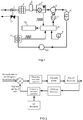
- the structural schematic diagram of a variable-frequency oil gas recovery control system for an oiling machine with a self-calibrated gas liquid ratio of the present invention is shown in Fig. 1 .
- the recovery control system comprises a frequency convertor controller 8, a recovery electrical motor 7, an oil gas switching valve 1, an oil gas recovery vacuum pump 5, an oil tank 6, an oiling pump 10, an oil gun 13, a temperature sensor 9 and an oiling flowmeter 11 which is used for measuring the oiling amount, wherein the oil gas switching valve, the oil gas recovery pump, the oil tank, the oiling pump 10, the oil gun 13 and the temperature sensor 9 are connected in sequence, the oiling flowmeter 11 is arranged on an oiling pipeline, and the oiling flowmeter 11 is in signal connection with the frequency convertor controller 8, the recovery electrical motor 7 and the oil gas recovery pump 5 in sequence.
- the temperature sensor 9 of the present invention is in signal connection with the frequency convertor controller 8, and is used to control the recovery electrical motor 7 and the oil gas recovery vacuum pump 5 by temperature signals.
- the present invention further comprises a VFM oil gas flowmeter 4 for measuring the oil gas recovery amount, wherein the VFM oil gas flowmeter 4 is in signal connection with the frequency convertor controller 8, and is used to control the recovery electrical motor 7 and the oil gas recovery vacuum pump 5 by oil gas recovery amount signals.
- the oil gas switching valve 1 is arranged at the muzzle of the oil gun 13; the present invention further comprises an oil gas filter 2 and a steady flow tank 3 which are arranged on an oil gas recovery pipeline between the oil gas switching valve 1 and the VFM oil gas flowmeter 4, wherein the oil gas switching valve 1, the oil gas filter 2, the steady flow tank 3, the VFM oil gas flowmeter 4, the oil gas recovery vacuum pump 5 and the oil tank 6 are connected in sequence.
- the VFM oil gas flowmeter 4 of the present invention is installed on an oil gas recovery pipeline between the steady flow tank 3 and the oil gas recovery vacuum pump 5, so that the effect of measuring the oil gas recovery amount can be increased.
- the present invention further comprises a display device 12 for displaying a gas-liquid ratio in real time, wherein the display device 12 is connected to a frequency convertor controller 8.
- the present invention has a real-time gas liquid ratio display function, which is favorable for system maintenance.
- the controller 8 is provided with more than two signal positions, each signal position corresponds to a certain temperature sensing range, and each temperature sensing range corresponds to one oil gas recovery ratio. Each signal position corresponds to one oil gas recovery ratio, so that the variation of the oil gas recovery ratio can be adapted.
- the signal positions are four positions which increase progressively in sequence or decrease progressively in sequence; the four signal positions respectively correspond to the following temperature sensing ranges in ascending order: (1) T ⁇ 0°C; (2) 0°C ⁇ T ⁇ 20°C; (3) 20°C ⁇ T ⁇ 30°C; (4) T>30°C; and T is the temperature sensed by the temperature sensor. In this way, the controller only needs to judge the temperature signal positions for the temperature T fed back by the temperature sensor 9.
- FIG. 2 A diagram of a control principle of the variable-frequency oil gas recovery control system for an oiling machine with a self-calibrated gas liquid ratio of the present invention is shown in Fig. 2 .
- the oil gas recovery control method utilizes the combination of a temperature signal and an oiling amount signal to control the speed of the recovery electrical motor, so that the preliminary adjustment of the oil gas recovery ratio is implemented; then utilizing an oil gas recovery amount signal and the oiling amount signal to calculate the real-time oil gas-liquid ratio, and adopting the real-time oil gas-liquid ratio as an output feedback signal of the recovery control system, so that the recovery control system is formed into a closed-loop recovery control system, realizing the self-adaptive adjustment of the oil gas recovery ratio; and the oil gas-liquid ratio refers to a ratio of the oil gas recovery amount to the oiling amount.
- the recovery control method of the present invention includes the following steps:
- Step 1 setting the oil gas recovery ratio ⁇ according to a temperature signal monitored in real time means: each temperature signal corresponding to a set temperature sensing range; each temperature sensing range corresponding to one oil gas recovery ratio, and selecting and setting the oil gas recovery ratio ⁇ according to a temperature signal monitored in real time.
Landscapes
- Engineering & Computer Science (AREA)
- Mechanical Engineering (AREA)
- Physics & Mathematics (AREA)
- Fluid Mechanics (AREA)
- Loading And Unloading Of Fuel Tanks Or Ships (AREA)
- Combined Controls Of Internal Combustion Engines (AREA)
Abstract
Description
- The present invention relates to an oiling machine, and in particular to a variable-frequency oil gas recovery control system and method for an oiling machine.
- At present, there are three types of gas station oil gas recovery technologies, i.e. primary recover, secondary recover and tertiary recovery:
- (a) Primary recovery means that as an oil tank truck is discharging oil into an oil depot of a gas station, oil gas which is discharged from the oil depot is recovered;
- (b) Secondary recovery means that as an oil gun is used to fill an automobile oil tank with gasoline, oil gas which is discharged from the oil tank is recovered; and
- (c) Tertiary recovery generally means that a recovery device is installed in the oil depot to carry out oil gas separation on extracted oil gas, discharge air and liquefy oil.
- As the gas station oil gas recovery standard of our country is becoming stricter and stricter, secondary oil gas recovery facilities start to be popularized and installed in gas stations. Currently, gas station oil gas recovery facilities which have high market shares all belong to foreign brands. According to modes for controlling the oil gas amount/the oiling amount ratio (oil gas recovery ratio, A/L), there can be the following four types:
- (1) Mode of controlling regulating valve by oil gas flow: This mode utilizes flow velocity in oiling to generate pressure to control the gas intake amount of the regulating valve in order to achieve the oil gas recovery ratio of about 1:1. This mode is adopted by Healy company and Elaflex company.
- (2) Pulse sensor mode adopting flow metering: This mode utilizes a signal of a flow sensor in oiling to control a variable-frequency motor or adjust the opening degree of a proportional valve. When oiling flow is large, the voltage signal frequency of the pulse sensor increases, the rotational speed of the variable-frequency motor increases or the opening degree of the proportional valve increases accordingly, and such a mode can achieve the oil gas recovery ratio of about 1:1. This mode is adopted by oil gas recovery equipment manufacturers including companies such as Gilbarco in USA, Tokheim in Europe, Wayne and NP.
- (3) Post-processing mode: This mode utilizes a vacuum pump to pump a great deal of air-containing oil gas adopting (1.4:1) to (2.4:1) in oiling back into an oil tank, and after the vapor pressure of the oil tank is increased, the redundant oil gas is sent into a combustion tower and burnt, or is recovered by adsorption, or a membrane separation recovery device is installed. Main equipment suppliers include major companies in Europe and USA, such as Hasstech, hirt and OPW.
- The above-mentioned oil gas recovery systems have the following defects:
- (1) Since the saturated vapor pressure of easy-to-gasify media, such as gasoline, can increase significantly as temperature increases, the easy-to-gasify media, such as gasoline, will be more easily volatilized at high temperature. Therefore, it is unreasonable for the previous two types of recovery systems to keep the fixed gas liquid ratio of 1:1. On the contrary, if the gas liquid ratio is high, taking the post-processing mode as an example, it will cause oil gas loss in the oil tank, and moreover, electrical energy will be wasted as well if the recovery ratio is too high.
- (2) In the mode of regulating oil gas recovery flow by means of the proportional valve, the opening degree of the proportional valve is adjusted by a spool, and the position of the spool of the proportional valve will get loose after the proportional valve is used for a period of time; moreover, an on-site worker may adjust the screw of the spool of the proportional valve without permission, and as a result, the performance of the proportional valve is changed, causing a nonlinear change in the gas liquid ratio of the system.
- (3) For the mode of regulating oil gas flow by means of the proportional valve or the mode of controlling the rotational speed of the motor of the vacuum pump only by the pulse frequency of flow metering, the system defaults the gas recovery amount of the vacuum pump to be constant; because the phenomena of gas recovery amount decrease and insufficient suction exist in the vacuum pump of the on-site oil gas recovery system, these will cause great influence on the gas liquid ratio of the system, and the system cannot be adjusted adaptively to achieve a correct gas liquid ratio.
- All the above-mentioned oil gas recovery systems do not have a real-time gas liquid ratio display function, so that on-site workers may not more visually keep track of the working conditions of the systems, bringing difficulty to system maintenance.
- In the process of transferring and metering fuel, especially gasoline, biofuel ethanol gasoline and other easy-to-gasify media, the fluid medium flows in a pipeline in the form of oil gas liquid coexistence. The change of the physiochemical properties of the transferred medium (for example, the biofuel ethanol gasoline is easier to gasify) will inevitably affect the gas liquid separation property in the process of pumping, and oil gas recovery control parameters will also need to be changed accordingly. The determination of the gas liquid ratio in oil gas recovery is closely related to the process of transfer, and depends on factors such as pipeline conditions, oil product properties, temperature and pressure condition in the process of transfer. Especially, temperature has significant influence on the volatility of easy-to-gasify media. According to a test, the environmental temperature of gas stations in our country is about 0 to 40 °C in general, and under this temperature condition, the variation range of the gas liquid ratio of oil gas volatilization is about 1-1.4.
- Based on the conditions of gas stations in our country, the above-mentioned oil gas recovery systems still have room for optimization, and the whole recovery systems can be made simpler and more efficient.
- The objective of the present invention is to overcome the shortcomings and defects in the prior art and provide a variable-frequency oil gas recovery control system for an oiling machine with a self-calibrated gas liquid ratio. The oil gas recovery control system utilizes the combination of a temperature signal and an oiling amount signal to control speed by variable frequency to implement the adjustment of the oil gas recovery ratio, and further a feedback signal is output to the system by an oil gas recovery amount signal and the oiling amount signal to form a closed-loop recovery system, consequently, the self-adaptive adjustment of the whole recovery system is achieved, so that the oil gas recovery ratio can be self-calibrated in a range of 1-1.4, tallying with the reality of gas stations in our country. The variable-frequency oil gas recovery control system for an oiling machine with a self-calibrated gas liquid ratio of the present invention is applicable to the oil gas recovery process of ordinary gasoline as well as ethanol gasoline. Meanwhile, the present invention provides a variable-frequency oil gas recovery control method for an oiling machine with a self-calibrated gas liquid ratio, which can realize the variable-frequency self-adaptive control of oil gas recovery, helping to realize the accurate control of the oil gas recovery ratio.
- In order to achieve the above-mentioned objective, the present invention is implemented by the following technical solution: a variable-frequency oil gas recovery control system for an oiling machine with a self-calibrated gas liquid ratio, comprising a controller, a recovery electrical motor, an oil gas switching valve, an oil gas recovery pump, an oil tank, an oiling pump, an oil gun, a temperature sensor and an oiling flowmeter which is used for measuring the oiling amount, wherein the oil gas switching valve, the oil gas recovery pump, the oil tank, the oiling pump, the oil gun and the temperature sensor are connected in sequence; the oiling flowmeter is arranged on an oiling pipeline, and is in signal connection with the controller, the recovery electrical motor and the oil gas recovery pump in sequence; the oil gas recovery control system is characterized in that the temperature sensor is in signal connection with the controller and is used to control the recovery electrical motor and the oil gas recovery pump by temperature signals; the oil gas recovery control system further comprises an oil gas flowmeter used for measuring the oil gas recovery amount recovery amount, which is in signal connection with the controller and which is used to control the recovery electrical motor and the oil gas recovery pump by oil gas recovery amount signals.
- In the above-mentioned solution, the controller is also in signal connection with the temperature sensor while being in signal connection with the oiling flowmeter, so that the oil gas recovery ratio is controlled simultaneously by an oiling amount signal and a temperature signal, thereby implementing the preliminary adjustment of the oil gas recovery ratio; the controller of the present invention is also in signal connection with the oil gas flowmeter, so that the oil gas recovery ratio can also be corrected by the actual gas liquid ratio fed back jointly by the oiling amount signal and the oil gas recovery amount signal simultaneously, consequently, the self-adaptive adjustment of the oil gas recovery ratio within a range of 1-1.4 is achieved, so that the recovery control system achieves a self-calibration function.
- The oil gas flowmeter is arranged on an oil gas recovery pipeline between the oil gas switching valve and the oil gas recovery pump. The design can conveniently monitor the oil gas recovery amount of the recovery control system in real time.
- The present invention further comprises a display device for displaying the gas liquid ratio in real time, wherein the display device is connected to the controller; and the gas liquid ratio refers to a ratio of the oil gas recovery amount to the oiling amount. Since the present invention has a real-time gas liquid ratio display function, the working condition of the system can be known more visually, which is favorable for system maintenance.
- The controller is provided with more than two signal positions, and each signal position corresponds to a certain temperature sensing range; and each temperature sensing range corresponds to one oil gas recovery ratio. Each signal position corresponds to one oil gas recovery ratio, and thus the controller can judge which temperature sensing range temperature T fed back by the temperature is in, and then regulates the oil gas recovery ratio.
- The signal positions are four positions which increase progressively in sequence or decrease progressively in sequence; the four signal positions respectively correspond to the following temperature sensing ranges in ascending order: (1) T≤0°C; (2) 0°C<T≤20°C; (3) 20°C<T≤30°C; (4) T>30°C; and T is the temperature sensed by the temperature sensor. In this way, the controller only needs to judge the temperature signal positions for the temperature T fed back by the temperature sensor.
- The oil gas recovery pump refers to an oil gas recovery vacuum pump; the controller refers to a frequency convertor controller; and the oil gas flowmeter refers to a VFM oil gas flowmeter.
- The oil gas switching valve is arranged at the muzzle of the oil gun; the oil gas recovery control system further comprises an oil gas filter and a steady flow tank which are arranged on an oil gas recovery pipeline between the oil gas switching valve and the oil gas flowmeter, wherein the oil gas switching valve, the oil gas filter, the steady flow tank, the oil gas flowmeter, the oil gas recovery pump and the oil tank are connected in sequence. The oil gas flowmeter of the present invention is installed between the steady flow tank and the oil gas recovery pump, so that the effect of measuring the oil gas recovery amount can be increased.
- Disclosed is a variable-frequency oil gas recovery control system for an oiling machine with a self-calibrated gas liquid ratio, characterized by utilizing the combination of a temperature signal and an oiling amount signal to control the speed of the recovery electrical motor, so that the preliminary adjustment of the oil gas recovery ratio is implemented; then utilizing an oil gas recovery amount signal and the oiling amount signal to calculate the real-time gas liquid ratio, and adopting the real-time gas liquid ratio as an output feedback signal of the recovery control system, so that the recovery control system is formed into a closed-loop recovery control system, realizing the self-adaptive adjustment of the oil gas recovery ratio; and the gas liquid ratio refers to a ratio of the oil gas recovery amount to the oiling amount.
- In the above-mentioned solution, the recovery control method of the present invention can realize the variable-frequency self-adaptive control of oil gas recovery, being beneficial to realizing the accurate control of the oil gas recovery ratio.
- More specifically, the recovery control method of the present invention includes the following steps:
- Step 1: When an oiling machine operates, setting an oil gas recovery ratio δ according to a temperature signal monitored in real time, calculating that the initial oil gas recovery amount Voil gas = δVoil, and controlling the speed of the recovery electrical motor according to the initial oil gas recovery amount Voil gas, so that the preliminary adjustment of the oil gas recovery ratio is implemented, wherein Voil is the oiling amount monitored in real time;
- Step 2: Calculating a real-time gas liquid ratio

- Step 3: Comparing the gas liquid ratio


- In Step 1, setting the oil gas recovery ratio δ according to a temperature signal monitored in real time means: each temperature signal corresponding to a set temperature sensing range; each temperature sensing range corresponding to one oil gas recovery ratio, and selecting and setting the oil gas recovery ratio δ according to a temperature signal monitored in real time.
- The control principle of the variable-frequency oil gas recovery control system for an oiling machine with a self-calibrated gas liquid ratio of the present invention is as follows: an appropriate oil gas recovery ratio δ is selected and set by utilizing a temperature signal, it is calculated in real time that the needed initial oil gas recovery amount Voil gas = δVoil in combination with the oiling amount Voil, and then the output frequency is adjusted by the controller according to the oil gas recovery capability of the oil gas recovery system, thereby controlling the speed of the recovery electrical motor. In the process of operation, oil gas recovery amount V'oil gas is fed back by the VFM oil gas flowmeter , a real-time gas liquid ratio


- The specific control principle of the oil gas recovery control system of the present invention is as follows: the variable-frequency motor is controlled by utilizing a pulse signal of an encoder of the oiling flowmeter in oiling to implement the control of the oil gas recovery vacuum pump. When oiling flow is large, the voltage signal frequency of the pulse sensor increases, the frequency convertor controller changes frequency to increase the rotational speed of the motor, so that the rotational speed of the vacuum pump is regulated, thereby achieving an appropriate oil gas recovery ratio.
- When temperature is high in summer, gasoline can be more easily volatilized, and under such a condition, only achieving the oil gas recovery ratio of 1:1 is not enough. Therefore, while the oiling amount is controlled, a temperature sensor signal is added, and temperature signals can be divided into four positions: 0 (and below), 0 -20, 20 - 30 and 30 (and above), each position corresponds to one oil gas recovery ratio, thereby realizing the variation of the oil gas recovery ratio. The temperature sensor outputs analog voltage of 0-5V. When the oiling temperature is high and the oiling amount is large, the voltage signal increases, the rotational speed of the variable-frequency motor increases accordingly, the rotational speed of the vacuum recovery pump increases, a higher oil gas recovery ratio is obtained, thereby achieving the variable-frequency self-adaptive control of the oil gas recovery ratio in the range of 1-1.4.
- In the operation of the system, by acquiring a pulse signal output by the VFM oil gas flowmeter, the frequency convertor controller calculates a ratio of the oiling amount to the oil gas recovery amount, so that a real gas liquid ratio under the current condition of the system can be known, the error of the gas-liquid ratio of the system is corrected, the speed of the recovery electrical motor is controlled according to the corrected gas liquid ratio, so that the self-adaptive adjustment of the oil gas recovery ratio is implemented, and meanwhile, the oil gas-liquid ratio is displayed on the display screen in real time.
- Compared with the prior art, the present invention has the following advantages and beneficial effects:
- 1. The recovery control system of the present invention has a self-calibration function, utilizes the combination of a temperature signal and an oiling amount signal to control speed by variable frequency to implement the adjustment of the oil gas recovery ratio, further a feedback signal is output to the system by the oil gas recovery amount signal and the oiling amount signal, so that a closed-loop recovery system is formed, consequently, the self-adaptive adjustment of the whole recovery system is achieved, so that the oil gas recovery ratio can be within a range of 1-1.4, tallying with the reality of gas stations in our country.
- 2. The recovery control system of the present invention reasonably sets an oil gas recovery ratio and a gas liquid ratio and can perform self-calibration, helping to protect the environment and save energy.
- 3. Since the recovery control system of the present invention has a real-time gas liquid ratio display function, the working condition of the system can be known more visually, which is favorable for system maintenance.
- 4. The variable-frequency oil gas recovery control system for an oiling machine with a self-calibrated gas liquid ratio of the present invention does not need to utilize a temperature signal to control the opening degree of a proportional valve to achieve an adjustable oil gas recovery ratio, and the gas flows of an oil gas recovery control system with a proportional valve and the oil gas recovery control system not adopting the proportional valve in the present invention are respectively 46L/min and 60L/min at the same frequency of 50Hz, so the oil gas recovery control system not adopting the proportional valve in the present invention greatly increases the flow of gas.
- 5. The recovery control method of the present invention can realize the variable-frequency self-adaptive control of oil gas recovery, helping to realize the accurate control of the oil gas recovery ratio.
-
-
Fig. 1 is a structural diagram showing a variable-frequency oil gas recovery control system for an oiling machine with a self-calibrated gas liquid ratio of the present invention; -
Fig. 2 is a diagram showing a control principle of a variable-frequency oil gas recovery control method for an oiling machine with a self-calibrated gas liquid ratio of the present invention; - Legends: 1.oil gas switching valve, 2. oil gas filter, 3. steady flow tank, 4. VFM oil gas flowmeter, 5. oil gas recovery vacuum pump, 6. oil tank, 7. recovery electrical motor, 8. frequency convertor controller, 9. temperature sensor, 10. oiling pump, 11. oiling flowmeter, 12. display device, 13.oil gun.
- The present invention is further described in detail below in reference to the drawings and a specific embodiment.
- The structural schematic diagram of a variable-frequency oil gas recovery control system for an oiling machine with a self-calibrated gas liquid ratio of the present invention is shown in
Fig. 1 . The recovery control system comprises a frequency convertor controller 8, a recoveryelectrical motor 7, an oil gas switching valve 1, an oil gas recovery vacuum pump 5, an oil tank 6, an oilingpump 10, anoil gun 13, a temperature sensor 9 and an oiling flowmeter 11 which is used for measuring the oiling amount, wherein the oil gas switching valve, the oil gas recovery pump, the oil tank, the oilingpump 10, theoil gun 13 and the temperature sensor 9 are connected in sequence, the oiling flowmeter 11 is arranged on an oiling pipeline, and the oiling flowmeter 11 is in signal connection with the frequency convertor controller 8, the recoveryelectrical motor 7 and the oil gas recovery pump 5 in sequence. The temperature sensor 9 of the present invention is in signal connection with the frequency convertor controller 8, and is used to control the recoveryelectrical motor 7 and the oil gas recovery vacuum pump 5 by temperature signals. The present invention further comprises a VFM oil gas flowmeter 4 for measuring the oil gas recovery amount, wherein the VFM oil gas flowmeter 4 is in signal connection with the frequency convertor controller 8, and is used to control the recoveryelectrical motor 7 and the oil gas recovery vacuum pump 5 by oil gas recovery amount signals. The oil gas switching valve 1 is arranged at the muzzle of theoil gun 13; the present invention further comprises an oil gas filter 2 and a steady flow tank 3 which are arranged on an oil gas recovery pipeline between the oil gas switching valve 1 and the VFM oil gas flowmeter 4, wherein the oil gas switching valve 1, the oil gas filter 2, the steady flow tank 3, the VFM oil gas flowmeter 4, the oil gas recovery vacuum pump 5 and the oil tank 6 are connected in sequence. - The VFM oil gas flowmeter 4 of the present invention is installed on an oil gas recovery pipeline between the steady flow tank 3 and the oil gas recovery vacuum pump 5, so that the effect of measuring the oil gas recovery amount can be increased. In order to more visually know the working condition of the system, the present invention further comprises a
display device 12 for displaying a gas-liquid ratio in real time, wherein thedisplay device 12 is connected to a frequency convertor controller 8. The present invention has a real-time gas liquid ratio display function, which is favorable for system maintenance. - The controller 8 is provided with more than two signal positions, each signal position corresponds to a certain temperature sensing range, and each temperature sensing range corresponds to one oil gas recovery ratio. Each signal position corresponds to one oil gas recovery ratio, so that the variation of the oil gas recovery ratio can be adapted. Specifically speaking, the signal positions are four positions which increase progressively in sequence or decrease progressively in sequence; the four signal positions respectively correspond to the following temperature sensing ranges in ascending order: (1) T≤0°C; (2) 0°C<T≤20°C; (3) 20°C<T≤30°C; (4) T>30°C; and T is the temperature sensed by the temperature sensor. In this way, the controller only needs to judge the temperature signal positions for the temperature T fed back by the temperature sensor 9.
- A diagram of a control principle of the variable-frequency oil gas recovery control system for an oiling machine with a self-calibrated gas liquid ratio of the present invention is shown in
Fig. 2 . The oil gas recovery control method utilizes the combination of a temperature signal and an oiling amount signal to control the speed of the recovery electrical motor, so that the preliminary adjustment of the oil gas recovery ratio is implemented; then utilizing an oil gas recovery amount signal and the oiling amount signal to calculate the real-time oil gas-liquid ratio, and adopting the real-time oil gas-liquid ratio as an output feedback signal of the recovery control system, so that the recovery control system is formed into a closed-loop recovery control system, realizing the self-adaptive adjustment of the oil gas recovery ratio; and the oil gas-liquid ratio refers to a ratio of the oil gas recovery amount to the oiling amount. - More specifically, the recovery control method of the present invention includes the following steps:
- Step 1: When an oiling machine operates, setting an oil gas recovery ratio δ according to a temperature signal monitored in real time, calculating that the initial oil gas recovery amount Voil gas = δVoil, and controlling the speed of the recovery electrical motor according to the initial oil gas recovery amount Voil gas, so that the preliminary adjustment of the oil gas recovery ratio is implemented, wherein Voil is the oiling amount monitored in real time;
- Step 2: Calculating a real-time gas liquid ratio
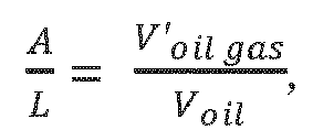
- Step 3: Comparing the gas liquid ratio


- In Step 1, setting the oil gas recovery ratio δ according to a temperature signal monitored in real time means: each temperature signal corresponding to a set temperature sensing range; each temperature sensing range corresponding to one oil gas recovery ratio, and selecting and setting the oil gas recovery ratio δ according to a temperature signal monitored in real time.
- The control principle of the variable-frequency oil gas recovery control system for an oiling machine with a self-calibrated gas liquid ratio of the present invention is as follows: an appropriate oil gas recovery ratio δ is selected and set by utilizing a temperature signal, it is calculated in real time that the needed initial oil gas recovery amount Voil gas = δVoil in combination with the oiling amount Voil, and then the output frequency is adjusted by the frequency convertor controller according to the oil gas recovery capability of the oil gas recovery system, thereby controlling the speed of the recovery electrical motor. In the process of operation, oil gas recovery amount V'oil gas is fed back by the VFM oil gas flowmeter , a real-time gas liquid ratio


- The above-mentioned embodiment is a preferred embodiment of the present invention, but the embodiments of the present invention are not limited by the above-mentioned embodiment, and any other alterations, modifications, replacements, combinations and simplifications which are made without departing from the spirit and principle of the present invention should all be equivalent replacement patterns, and should all be included in the protection scope of the present invention.
Claims (10)
- A variable-frequency oil gas recovery control system for an oiling machine with a self-calibrated gas liquid ratio, comprising a controller, a recovery electrical motor, an oil gas switching valve, an oil gas recovery pump, an oil tank, an oiling pump, an oil gun, a temperature sensor and an oiling flowmeter which is used for measuring the oiling amount, wherein the oil gas switching valve, the oil gas recovery pump, the oil tank, the oiling pump, the oil gun and the temperature sensor are connected in sequence; the oiling flowmeter is arranged on an oiling pipeline, and is in signal connection with the controller, the recovery electrical motor and the oil gas recovery pump in sequence; characterized in that the temperature sensor is in signal connection with the controller, and is used to control the recovery electrical motor and the oil gas recovery pump by temperature signals; further comprising an oil gas flowmeter used for measuring the oil gas recovery amount, which is in signal connection with the controller and which is used to control the recovery electrical motor and the oil gas recovery pump by oil gas recovery amount signals.
- The variable-frequency oil gas recovery control system for an oiling machine with a self-calibrated gas liquid ratio according to claim 1, characterized in that the oil gas flowmeter is arranged on an oil gas recovery pipeline between the oil gas switching valve and the oil gas recovery pump.
- The variable-frequency oil gas recovery control system for an oiling machine with a self-calibrated gas liquid ratio according to claim 1, characterized by further comprising a display device for displaying a gas liquid ratio in real time, wherein the display device is connected to the controller; and the gas liquid ratio refers to a ratio of the oil gas recovery amount to the oiling amount.
- The variable-frequency oil gas recovery control system for an oiling machine with a self-calibrated gas liquid ratio according to claim 1, characterized in that the controller is provided with more than two signal positions, and each signal position corresponds to a certain temperature sensing range; and each temperature sensing range corresponds to one oil gas recovery ratio.
- The variable-frequency oil gas recovery control system for an oiling machine with a self-calibrated gas liquid ratio according to claim 4, characterized in that the signal positions are four positions which increase progressively in sequence or decrease progressively in sequence; the four signal positions respectively correspond to the following temperature sensing ranges in ascending order: (1) T≤0°C; (2) 0°C<T≤20°C; (3) 20°C<T≤30°C; (4) T>30°C; and T is temperature sensed by the temperature sensor.
- The variable-frequency oil gas recovery control system for an oiling machine with a self-calibrated gas liquid ratio according to claim 1, characterized in that the oil gas recovery pump refers to an oil gas recovery vacuum pump; the controller refers to a frequency convertor controller; and the oil gas flowmeter refers to a VFM oil gas flowmeter.
- The variable-frequency oil gas recovery control system for an oiling machine with a self-calibrated gas liquid ratio according to any one of claims 1-6, characterized in that the oil gas switching valve is arranged at the muzzle of the oil gun; further comprising an oil gas filter and a steady flow tank which are arranged on an oil gas recovery pipeline between the oil gas switching valve and the oil gas flowmeter, wherein the oil gas switching valve, the oil gas filter, the steady flow tank, the oil gas flowmeter, the oil gas recovery pump and the oil tank are connected in sequence.
- A variable-frequency oil gas recovery control method for an oiling machine with a self-calibrated gas liquid ratio, characterized by utilizing the combination of a temperature signal and an oiling amount signal to control the speed of the recovery electrical motor, so that the preliminary adjustment of the oil gas recovery ratio is implemented; then utilizing an oil gas recovery amount signal and the oiling amount signal to calculate the real-time gas liquid ratio, and adopting the real-time gas liquid ratio as an output feedback signal of the recovery control system, so that the recovery control system is formed into a closed-loop recovery control system, realizing the self-adaptive adjustment of the oil gas recovery ratio; and the gas liquid ratio refers to a ratio of the oil gas recovery amount to the oiling amount.
- The variable-frequency oil gas recovery control method for an oiling machine with a self-calibrated gas liquid ratio according to claim 8, characterized by comprising the following steps:Step 1: When an oiling machine operates, setting an oil gas recovery ratio δ according to a temperature signal monitored in real time, calculating that the initial oil gas recovery amount Voil gas = δVoil, and controlling the speed of the recovery electrical motor according to the initial oil gas recovery amount Voil gas, so that the preliminary adjustment of the oil gas recovery ratio is implemented, wherein Voil is the oiling amount monitored in real time;Step 2: Calculating a real-time gas liquid ratio
 Step 3: Comparing the oil gas-liquid ratio


- The variable-frequency oil gas recovery control method for an oiling machine with a self-calibrated gas liquid ratio according to claim 9, characterized in that in Step 1, setting the oil gas recovery ratio δ according to a temperature signal monitored in real time means: each temperature signal corresponding to a set temperature sensing range; each temperature sensing range corresponding to one oil gas recovery ratio, and selecting and setting the oil gas recovery ratio δ according to a temperature signal monitored in real time.
Applications Claiming Priority (2)
| Application Number | Priority Date | Filing Date | Title |
|---|---|---|---|
| CN201410811474.4A CN104528627B (en) | 2014-12-19 | 2014-12-19 | A kind of self-alignment fuel charger variable frequency oil gas recovery control system of gas liquid ratio and method |
| PCT/CN2015/082837 WO2016095486A1 (en) | 2014-12-19 | 2015-06-30 | Frequency variable oil gas recovery control system and method for oiling machine with self-calibrated gas liquid ratio |
Publications (3)
| Publication Number | Publication Date |
|---|---|
| EP3235778A1 true EP3235778A1 (en) | 2017-10-25 |
| EP3235778A4 EP3235778A4 (en) | 2018-10-10 |
| EP3235778B1 EP3235778B1 (en) | 2021-01-20 |
Family
ID=52844325
Family Applications (1)
| Application Number | Title | Priority Date | Filing Date |
|---|---|---|---|
| EP15868998.4A Not-in-force EP3235778B1 (en) | 2014-12-19 | 2015-06-30 | Frequency variable oil gas recovery control system and method for oiling machine with self-calibrated gas liquid ratio |
Country Status (4)
| Country | Link |
|---|---|
| US (1) | US10501309B2 (en) |
| EP (1) | EP3235778B1 (en) |
| CN (1) | CN104528627B (en) |
| WO (1) | WO2016095486A1 (en) |
Cited By (3)
| Publication number | Priority date | Publication date | Assignee | Title |
|---|---|---|---|---|
| CN109734043A (en) * | 2018-12-18 | 2019-05-10 | 宝泰科技有限公司 | A kind of automated calibration system for gas station oil gas recycling |
| CN111471479A (en) * | 2020-04-14 | 2020-07-31 | 青岛飞普思环保科技有限公司 | Oil absorption process for oil gas recovery |
| CN118526915A (en) * | 2024-05-13 | 2024-08-23 | 北京善恩能源工程有限公司 | Oil gas recovery device combining condensation and adsorption |
Families Citing this family (23)
| Publication number | Priority date | Publication date | Assignee | Title |
|---|---|---|---|---|
| CN104528627B (en) * | 2014-12-19 | 2017-10-20 | 华南理工大学 | A kind of self-alignment fuel charger variable frequency oil gas recovery control system of gas liquid ratio and method |
| CN105084288B (en) * | 2015-08-13 | 2017-08-29 | 中国石油化工股份有限公司青岛安全工程研究院 | Gas station oil gas reclaims seal automatic monitoring method |
| CN105060232B (en) * | 2015-08-13 | 2018-05-08 | 中国石油化工股份有限公司 | Oil depot petroleum vapor recovery integrated monitoring |
| CN105480927A (en) * | 2015-12-17 | 2016-04-13 | 合肥创博信息科技有限公司 | Automatic monitoring device for oil gas recovery |
| DK3369700T3 (en) * | 2017-03-03 | 2021-08-23 | Elaflex Hiby Gmbh & Co Kg | DRAIN VALVE FOR TWO MAXIMUM VOLUME FLOWS |
| CN107697879B (en) * | 2017-09-27 | 2024-01-26 | 北京恒合信业技术股份有限公司 | Oil gas recovery on-line monitoring system of filling station |
| CN110002390A (en) * | 2019-04-15 | 2019-07-12 | 佛山市南海泽睿科技有限公司 | A kind of oil-gas recovery method based on support vector machines |
| CN110015631A (en) * | 2019-04-15 | 2019-07-16 | 佛山市南海泽睿科技有限公司 | A kind of oil-gas recovery method neural network based |
| CN109941950A (en) * | 2019-04-25 | 2019-06-28 | 佛山市南海泽睿科技有限公司 | A kind of oil-gas recovery method based on CART algorithm |
| CN112110407B (en) * | 2019-06-19 | 2022-06-28 | 中国石油化工股份有限公司 | Double-frequency-conversion oil gas recovery gas-liquid ratio adjusting device and method |
| CN111071978B (en) * | 2019-12-23 | 2021-10-15 | 航天科技控股集团股份有限公司 | A system and method for inputting refueling gun verification information based on location information |
| CN111086969B (en) * | 2020-01-13 | 2025-08-15 | 浙江瑞森路政设施有限公司 | Intelligent flow control transmitter |
| CN111874855A (en) * | 2020-06-30 | 2020-11-03 | 浙江瑞森路政设施有限公司 | A gas-liquid ratio control device |
| CN111928674A (en) * | 2020-08-13 | 2020-11-13 | 楚雄滇中有色金属有限责任公司 | Method for accurately controlling baking temperature of PS converter |
| CN112555140B (en) * | 2020-10-30 | 2023-05-23 | 中国航发西安动力控制科技有限公司 | Calibration equipment and calibration method for gas-liquid ratio tester |
| CN113049187B (en) * | 2020-11-05 | 2021-12-17 | 东营市创元石油机械制造有限公司 | Leakage concentration analysis system and method applying flow monitoring |
| CN113443290B (en) * | 2021-06-23 | 2022-08-23 | 成都百斯纳克科技有限公司 | Oil-gas flow adjusting method, system, terminal and medium |
| CN113548633A (en) * | 2021-08-04 | 2021-10-26 | 维德路特油站设备(上海)有限公司 | Oil gas recovery system and refueling equipment |
| CN115072646B (en) * | 2022-05-19 | 2025-08-12 | 三盈联合科技股份有限公司 | Oil gas intelligent recovery system of filling station |
| CN116216624B (en) * | 2022-12-29 | 2025-11-21 | 广州发展碧辟油品有限公司 | Oil gas recovery and adjustment method |
| CN118306939A (en) * | 2022-12-30 | 2024-07-09 | 苏州三米格科技有限公司 | A closed-loop system and method for automatically controlling oil and gas processing capacity |
| CN117699729B (en) * | 2024-01-04 | 2026-04-14 | 合肥科迈捷智能传感技术股份有限公司 | Gas-liquid ratio control method for secondary oil-gas recovery of oiling machine |
| CN119079923A (en) * | 2024-11-07 | 2024-12-06 | 临沂市计量检定所 | A method and system for measuring and verifying fuel dispenser |
Family Cites Families (20)
| Publication number | Priority date | Publication date | Assignee | Title |
|---|---|---|---|---|
| US5156199A (en) * | 1990-12-11 | 1992-10-20 | Gilbarco, Inc. | Control system for temperature compensated vapor recovery in gasoline dispenser |
| US5269353A (en) | 1992-10-29 | 1993-12-14 | Gilbarco, Inc. | Vapor pump control |
| US5507325A (en) | 1993-11-17 | 1996-04-16 | Finlayson; Ian M. | Vapor recovery system for fuel dispensers |
| US6170539B1 (en) * | 1999-09-29 | 2001-01-09 | Mokori Commerce Systems Inc. | Vapor recovery system for fuel dispenser |
| US6460579B2 (en) * | 1999-11-17 | 2002-10-08 | Gilbarco Inc. | Vapor flow and hydrocarbon concentration sensor for improved vapor recovery in fuel dispensers |
| US6830080B2 (en) * | 2003-03-13 | 2004-12-14 | Gilbarco Inc. | Output control for turbine vapor flow meter |
| FR2924706B1 (en) * | 2007-12-05 | 2012-10-19 | Tokheim Holding Bv | FUEL DELIVERY INSTALLATION COMPRISING A VAPOR RECOVERY DEVICE AND A METHOD USED IN THE USE OF THIS INSTALLATION. |
| CN101691199B (en) * | 2009-11-03 | 2012-12-19 | 中国石油化工股份有限公司 | On-line monitoring system for oil gas recovery of gas station |
| CN102173371A (en) * | 2011-01-28 | 2011-09-07 | 华南理工大学 | Novel oil gas recovery control system of gas station |
| CN202022744U (en) * | 2011-01-28 | 2011-11-02 | 华南理工大学 | Novel gas station oil gas recovery control system |
| CN202089758U (en) * | 2011-03-03 | 2011-12-28 | 中机生产力促进中心 | Gas station second-stage closed-loop type oil gas recycling system |
| JP5706784B2 (en) * | 2011-08-17 | 2015-04-22 | トキコテクノ株式会社 | Liquefied gas filling system |
| CN202246023U (en) * | 2011-09-02 | 2012-05-30 | 托肯恒山科技(广州)有限公司 | IC (Integrated Circuit) card vehicle-mounted machine for fuel loading |
| CN102515078B (en) * | 2011-12-21 | 2014-12-03 | 华南理工大学 | A metering control system of frequency conversion fuel dispenser and its metering accuracy control method |
| CN102718178B (en) * | 2012-06-12 | 2015-04-22 | 佛山市海卓瑞流体控制工程有限公司 | Variable-frequency oil gas recovery control system of fuel dispenser |
| CN202687941U (en) * | 2012-06-12 | 2013-01-23 | 佛山市海卓瑞流体控制工程有限公司 | Variable frequency oil gas recycling control system of fueling machine |
| CN203048574U (en) * | 2012-11-23 | 2013-07-10 | 托肯恒山科技(广州)有限公司 | Electronic centralized oil and gas recovery system |
| CN103601145A (en) * | 2013-10-17 | 2014-02-26 | 中国石油化工股份有限公司 | Gas station oiling oil gas recovery closed loop gas liquid ratio adjusting method |
| CN104528627B (en) * | 2014-12-19 | 2017-10-20 | 华南理工大学 | A kind of self-alignment fuel charger variable frequency oil gas recovery control system of gas liquid ratio and method |
| CN204369559U (en) * | 2014-12-19 | 2015-06-03 | 华南理工大学 | A kind of gas liquid ratio self-alignment fuel charger variable frequency oil gas recovery control system |
-
2014
- 2014-12-19 CN CN201410811474.4A patent/CN104528627B/en not_active Expired - Fee Related
-
2015
- 2015-06-30 WO PCT/CN2015/082837 patent/WO2016095486A1/en not_active Ceased
- 2015-06-30 US US15/536,445 patent/US10501309B2/en not_active Expired - Fee Related
- 2015-06-30 EP EP15868998.4A patent/EP3235778B1/en not_active Not-in-force
Cited By (4)
| Publication number | Priority date | Publication date | Assignee | Title |
|---|---|---|---|---|
| CN109734043A (en) * | 2018-12-18 | 2019-05-10 | 宝泰科技有限公司 | A kind of automated calibration system for gas station oil gas recycling |
| CN109734043B (en) * | 2018-12-18 | 2020-06-26 | 宝泰科技有限公司 | Automatic calibration system for oil gas recovery of gas station |
| CN111471479A (en) * | 2020-04-14 | 2020-07-31 | 青岛飞普思环保科技有限公司 | Oil absorption process for oil gas recovery |
| CN118526915A (en) * | 2024-05-13 | 2024-08-23 | 北京善恩能源工程有限公司 | Oil gas recovery device combining condensation and adsorption |
Also Published As
| Publication number | Publication date |
|---|---|
| US20170349427A1 (en) | 2017-12-07 |
| EP3235778A4 (en) | 2018-10-10 |
| WO2016095486A1 (en) | 2016-06-23 |
| EP3235778B1 (en) | 2021-01-20 |
| CN104528627B (en) | 2017-10-20 |
| CN104528627A (en) | 2015-04-22 |
| US10501309B2 (en) | 2019-12-10 |
Similar Documents
| Publication | Publication Date | Title |
|---|---|---|
| EP3235778B1 (en) | Frequency variable oil gas recovery control system and method for oiling machine with self-calibrated gas liquid ratio | |
| CN204422227U (en) | A kind of Aviation Fuel nozzle characteristic testing platform | |
| EP3109442A1 (en) | Fuel supply line system used for gas turbine | |
| CN104931266B (en) | A kind of airplane engine fuel oil analog control system and adjusting method | |
| CN104375529B (en) | A kind of control pressurer system of engine nozzle experiment | |
| CN104931244A (en) | High-temperature and large-flow combined test bench and method for aviation pneumatic valve | |
| CN114314486B (en) | System and method for adjusting secondary oil-gas recovery gas-liquid ratio of gas station | |
| CN103601145A (en) | Gas station oiling oil gas recovery closed loop gas liquid ratio adjusting method | |
| CN105679187A (en) | Industrial production physical simulation training and examination system | |
| TW201407148A (en) | Transmission solenoid valve abnormality detecting method and system thereof | |
| CN204369559U (en) | A kind of gas liquid ratio self-alignment fuel charger variable frequency oil gas recovery control system | |
| CN104005866A (en) | Method and control device for protecting cam rotor pump of diesel engine from cavitation | |
| CN104329173B (en) | The control method of a kind of gas turbine fuel and air mixing ratio and device | |
| CN106644250B (en) | The mancarried device of air pressure measurement | |
| CN204610308U (en) | Aircraft fuel pump the property test platform of centrifugal pump | |
| CN203148509U (en) | Negative pressure chamber voltage stabilizer of differential pressure transmitter of LNG production equipment | |
| CN203494410U (en) | Automatic flow-adjusted gas mixer | |
| CN110118637B (en) | Aircraft refueling joint comprehensive test system | |
| CN112594065A (en) | Gas fuel conditioning system for gas turbine engine and method of designing same | |
| CN219198877U (en) | Intelligent gas pressurizing device | |
| CN104697769A (en) | Opening pressure gas measuring device and method for oil pump pressure limiting valve | |
| CN202687941U (en) | Variable frequency oil gas recycling control system of fueling machine | |
| WO2019182895A1 (en) | Pressure regulating mass flow system for multipoint gaseous fuel injection | |
| CN206684590U (en) | The accurate control set for adjusting of dynamic analog vacuum system pressure | |
| CN106641732B (en) | A kind of product oil entrucking metering regulating device |
Legal Events
| Date | Code | Title | Description |
|---|---|---|---|
| STAA | Information on the status of an ep patent application or granted ep patent |
Free format text: STATUS: THE INTERNATIONAL PUBLICATION HAS BEEN MADE |
|
| PUAI | Public reference made under article 153(3) epc to a published international application that has entered the european phase |
Free format text: ORIGINAL CODE: 0009012 |
|
| STAA | Information on the status of an ep patent application or granted ep patent |
Free format text: STATUS: REQUEST FOR EXAMINATION WAS MADE |
|
| 17P | Request for examination filed |
Effective date: 20170515 |
|
| AK | Designated contracting states |
Kind code of ref document: A1 Designated state(s): AL AT BE BG CH CY CZ DE DK EE ES FI FR GB GR HR HU IE IS IT LI LT LU LV MC MK MT NL NO PL PT RO RS SE SI SK SM TR |
|
| AX | Request for extension of the european patent |
Extension state: BA ME |
|
| DAV | Request for validation of the european patent (deleted) | ||
| DAX | Request for extension of the european patent (deleted) | ||
| A4 | Supplementary search report drawn up and despatched |
Effective date: 20180911 |
|
| RIC1 | Information provided on ipc code assigned before grant |
Ipc: B67D 7/04 20100101ALI20180903BHEP Ipc: B67D 7/54 20100101AFI20180903BHEP |
|
| STAA | Information on the status of an ep patent application or granted ep patent |
Free format text: STATUS: EXAMINATION IS IN PROGRESS |
|
| 17Q | First examination report despatched |
Effective date: 20190508 |
|
| RAP1 | Party data changed (applicant data changed or rights of an application transferred) |
Owner name: SOUTH CHINA UNIVERSITY OF TECHNOLOGY |
|
| GRAP | Despatch of communication of intention to grant a patent |
Free format text: ORIGINAL CODE: EPIDOSNIGR1 |
|
| STAA | Information on the status of an ep patent application or granted ep patent |
Free format text: STATUS: GRANT OF PATENT IS INTENDED |
|
| INTG | Intention to grant announced |
Effective date: 20200821 |
|
| GRAS | Grant fee paid |
Free format text: ORIGINAL CODE: EPIDOSNIGR3 |
|
| GRAA | (expected) grant |
Free format text: ORIGINAL CODE: 0009210 |
|
| STAA | Information on the status of an ep patent application or granted ep patent |
Free format text: STATUS: THE PATENT HAS BEEN GRANTED |
|
| AK | Designated contracting states |
Kind code of ref document: B1 Designated state(s): AL AT BE BG CH CY CZ DE DK EE ES FI FR GB GR HR HU IE IS IT LI LT LU LV MC MK MT NL NO PL PT RO RS SE SI SK SM TR |
|
| REG | Reference to a national code |
Ref country code: GB Ref legal event code: FG4D |
|
| REG | Reference to a national code |
Ref country code: CH Ref legal event code: EP |
|
| REG | Reference to a national code |
Ref country code: AT Ref legal event code: REF Ref document number: 1356233 Country of ref document: AT Kind code of ref document: T Effective date: 20210215 |
|
| REG | Reference to a national code |
Ref country code: IE Ref legal event code: FG4D |
|
| REG | Reference to a national code |
Ref country code: DE Ref legal event code: R096 Ref document number: 602015065082 Country of ref document: DE |
|
| REG | Reference to a national code |
Ref country code: NL Ref legal event code: MP Effective date: 20210120 |
|
| REG | Reference to a national code |
Ref country code: LT Ref legal event code: MG9D |
|
| REG | Reference to a national code |
Ref country code: AT Ref legal event code: MK05 Ref document number: 1356233 Country of ref document: AT Kind code of ref document: T Effective date: 20210120 |
|
| PG25 | Lapsed in a contracting state [announced via postgrant information from national office to epo] |
Ref country code: BG Free format text: LAPSE BECAUSE OF FAILURE TO SUBMIT A TRANSLATION OF THE DESCRIPTION OR TO PAY THE FEE WITHIN THE PRESCRIBED TIME-LIMIT Effective date: 20210420 Ref country code: HR Free format text: LAPSE BECAUSE OF FAILURE TO SUBMIT A TRANSLATION OF THE DESCRIPTION OR TO PAY THE FEE WITHIN THE PRESCRIBED TIME-LIMIT Effective date: 20210120 Ref country code: GR Free format text: LAPSE BECAUSE OF FAILURE TO SUBMIT A TRANSLATION OF THE DESCRIPTION OR TO PAY THE FEE WITHIN THE PRESCRIBED TIME-LIMIT Effective date: 20210421 Ref country code: FI Free format text: LAPSE BECAUSE OF FAILURE TO SUBMIT A TRANSLATION OF THE DESCRIPTION OR TO PAY THE FEE WITHIN THE PRESCRIBED TIME-LIMIT Effective date: 20210120 Ref country code: LT Free format text: LAPSE BECAUSE OF FAILURE TO SUBMIT A TRANSLATION OF THE DESCRIPTION OR TO PAY THE FEE WITHIN THE PRESCRIBED TIME-LIMIT Effective date: 20210120 Ref country code: NO Free format text: LAPSE BECAUSE OF FAILURE TO SUBMIT A TRANSLATION OF THE DESCRIPTION OR TO PAY THE FEE WITHIN THE PRESCRIBED TIME-LIMIT Effective date: 20210420 Ref country code: PT Free format text: LAPSE BECAUSE OF FAILURE TO SUBMIT A TRANSLATION OF THE DESCRIPTION OR TO PAY THE FEE WITHIN THE PRESCRIBED TIME-LIMIT Effective date: 20210520 |
|
| PGFP | Annual fee paid to national office [announced via postgrant information from national office to epo] |
Ref country code: FR Payment date: 20210630 Year of fee payment: 7 |
|
| PG25 | Lapsed in a contracting state [announced via postgrant information from national office to epo] |
Ref country code: AT Free format text: LAPSE BECAUSE OF FAILURE TO SUBMIT A TRANSLATION OF THE DESCRIPTION OR TO PAY THE FEE WITHIN THE PRESCRIBED TIME-LIMIT Effective date: 20210120 Ref country code: RS Free format text: LAPSE BECAUSE OF FAILURE TO SUBMIT A TRANSLATION OF THE DESCRIPTION OR TO PAY THE FEE WITHIN THE PRESCRIBED TIME-LIMIT Effective date: 20210120 Ref country code: PL Free format text: LAPSE BECAUSE OF FAILURE TO SUBMIT A TRANSLATION OF THE DESCRIPTION OR TO PAY THE FEE WITHIN THE PRESCRIBED TIME-LIMIT Effective date: 20210120 Ref country code: LV Free format text: LAPSE BECAUSE OF FAILURE TO SUBMIT A TRANSLATION OF THE DESCRIPTION OR TO PAY THE FEE WITHIN THE PRESCRIBED TIME-LIMIT Effective date: 20210120 Ref country code: SE Free format text: LAPSE BECAUSE OF FAILURE TO SUBMIT A TRANSLATION OF THE DESCRIPTION OR TO PAY THE FEE WITHIN THE PRESCRIBED TIME-LIMIT Effective date: 20210120 |
|
| PG25 | Lapsed in a contracting state [announced via postgrant information from national office to epo] |
Ref country code: IS Free format text: LAPSE BECAUSE OF FAILURE TO SUBMIT A TRANSLATION OF THE DESCRIPTION OR TO PAY THE FEE WITHIN THE PRESCRIBED TIME-LIMIT Effective date: 20210520 |
|
| REG | Reference to a national code |
Ref country code: DE Ref legal event code: R097 Ref document number: 602015065082 Country of ref document: DE |
|
| PG25 | Lapsed in a contracting state [announced via postgrant information from national office to epo] |
Ref country code: SM Free format text: LAPSE BECAUSE OF FAILURE TO SUBMIT A TRANSLATION OF THE DESCRIPTION OR TO PAY THE FEE WITHIN THE PRESCRIBED TIME-LIMIT Effective date: 20210120 Ref country code: CZ Free format text: LAPSE BECAUSE OF FAILURE TO SUBMIT A TRANSLATION OF THE DESCRIPTION OR TO PAY THE FEE WITHIN THE PRESCRIBED TIME-LIMIT Effective date: 20210120 Ref country code: EE Free format text: LAPSE BECAUSE OF FAILURE TO SUBMIT A TRANSLATION OF THE DESCRIPTION OR TO PAY THE FEE WITHIN THE PRESCRIBED TIME-LIMIT Effective date: 20210120 |
|
| PLBE | No opposition filed within time limit |
Free format text: ORIGINAL CODE: 0009261 |
|
| STAA | Information on the status of an ep patent application or granted ep patent |
Free format text: STATUS: NO OPPOSITION FILED WITHIN TIME LIMIT |
|
| PG25 | Lapsed in a contracting state [announced via postgrant information from national office to epo] |
Ref country code: SK Free format text: LAPSE BECAUSE OF FAILURE TO SUBMIT A TRANSLATION OF THE DESCRIPTION OR TO PAY THE FEE WITHIN THE PRESCRIBED TIME-LIMIT Effective date: 20210120 Ref country code: RO Free format text: LAPSE BECAUSE OF FAILURE TO SUBMIT A TRANSLATION OF THE DESCRIPTION OR TO PAY THE FEE WITHIN THE PRESCRIBED TIME-LIMIT Effective date: 20210120 Ref country code: DK Free format text: LAPSE BECAUSE OF FAILURE TO SUBMIT A TRANSLATION OF THE DESCRIPTION OR TO PAY THE FEE WITHIN THE PRESCRIBED TIME-LIMIT Effective date: 20210120 |
|
| 26N | No opposition filed |
Effective date: 20211021 |
|
| REG | Reference to a national code |
Ref country code: DE Ref legal event code: R119 Ref document number: 602015065082 Country of ref document: DE |
|
| PG25 | Lapsed in a contracting state [announced via postgrant information from national office to epo] |
Ref country code: MC Free format text: LAPSE BECAUSE OF FAILURE TO SUBMIT A TRANSLATION OF THE DESCRIPTION OR TO PAY THE FEE WITHIN THE PRESCRIBED TIME-LIMIT Effective date: 20210120 Ref country code: AL Free format text: LAPSE BECAUSE OF FAILURE TO SUBMIT A TRANSLATION OF THE DESCRIPTION OR TO PAY THE FEE WITHIN THE PRESCRIBED TIME-LIMIT Effective date: 20210120 Ref country code: ES Free format text: LAPSE BECAUSE OF FAILURE TO SUBMIT A TRANSLATION OF THE DESCRIPTION OR TO PAY THE FEE WITHIN THE PRESCRIBED TIME-LIMIT Effective date: 20210120 |
|
| REG | Reference to a national code |
Ref country code: CH Ref legal event code: PL |
|
| GBPC | Gb: european patent ceased through non-payment of renewal fee |
Effective date: 20210630 |
|
| PG25 | Lapsed in a contracting state [announced via postgrant information from national office to epo] |
Ref country code: SI Free format text: LAPSE BECAUSE OF FAILURE TO SUBMIT A TRANSLATION OF THE DESCRIPTION OR TO PAY THE FEE WITHIN THE PRESCRIBED TIME-LIMIT Effective date: 20210120 |
|
| REG | Reference to a national code |
Ref country code: BE Ref legal event code: MM Effective date: 20210630 |
|
| PG25 | Lapsed in a contracting state [announced via postgrant information from national office to epo] |
Ref country code: LU Free format text: LAPSE BECAUSE OF NON-PAYMENT OF DUE FEES Effective date: 20210630 |
|
| PG25 | Lapsed in a contracting state [announced via postgrant information from national office to epo] |
Ref country code: LI Free format text: LAPSE BECAUSE OF NON-PAYMENT OF DUE FEES Effective date: 20210630 Ref country code: IT Free format text: LAPSE BECAUSE OF FAILURE TO SUBMIT A TRANSLATION OF THE DESCRIPTION OR TO PAY THE FEE WITHIN THE PRESCRIBED TIME-LIMIT Effective date: 20210120 Ref country code: IE Free format text: LAPSE BECAUSE OF NON-PAYMENT OF DUE FEES Effective date: 20210630 Ref country code: GB Free format text: LAPSE BECAUSE OF NON-PAYMENT OF DUE FEES Effective date: 20210630 Ref country code: DE Free format text: LAPSE BECAUSE OF NON-PAYMENT OF DUE FEES Effective date: 20220101 Ref country code: CH Free format text: LAPSE BECAUSE OF NON-PAYMENT OF DUE FEES Effective date: 20210630 |
|
| PG25 | Lapsed in a contracting state [announced via postgrant information from national office to epo] |
Ref country code: IS Free format text: LAPSE BECAUSE OF FAILURE TO SUBMIT A TRANSLATION OF THE DESCRIPTION OR TO PAY THE FEE WITHIN THE PRESCRIBED TIME-LIMIT Effective date: 20210520 |
|
| PG25 | Lapsed in a contracting state [announced via postgrant information from national office to epo] |
Ref country code: BE Free format text: LAPSE BECAUSE OF NON-PAYMENT OF DUE FEES Effective date: 20210630 |
|
| PG25 | Lapsed in a contracting state [announced via postgrant information from national office to epo] |
Ref country code: FR Free format text: LAPSE BECAUSE OF NON-PAYMENT OF DUE FEES Effective date: 20220630 |
|
| PG25 | Lapsed in a contracting state [announced via postgrant information from national office to epo] |
Ref country code: HU Free format text: LAPSE BECAUSE OF FAILURE TO SUBMIT A TRANSLATION OF THE DESCRIPTION OR TO PAY THE FEE WITHIN THE PRESCRIBED TIME-LIMIT; INVALID AB INITIO Effective date: 20150630 |
|
| PG25 | Lapsed in a contracting state [announced via postgrant information from national office to epo] |
Ref country code: NL Free format text: LAPSE BECAUSE OF NON-PAYMENT OF DUE FEES Effective date: 20210120 Ref country code: CY Free format text: LAPSE BECAUSE OF FAILURE TO SUBMIT A TRANSLATION OF THE DESCRIPTION OR TO PAY THE FEE WITHIN THE PRESCRIBED TIME-LIMIT Effective date: 20210120 |
|
| PG25 | Lapsed in a contracting state [announced via postgrant information from national office to epo] |
Ref country code: MK Free format text: LAPSE BECAUSE OF FAILURE TO SUBMIT A TRANSLATION OF THE DESCRIPTION OR TO PAY THE FEE WITHIN THE PRESCRIBED TIME-LIMIT Effective date: 20210120 |
|
| PG25 | Lapsed in a contracting state [announced via postgrant information from national office to epo] |
Ref country code: TR Free format text: LAPSE BECAUSE OF FAILURE TO SUBMIT A TRANSLATION OF THE DESCRIPTION OR TO PAY THE FEE WITHIN THE PRESCRIBED TIME-LIMIT Effective date: 20210120 |
|
| PG25 | Lapsed in a contracting state [announced via postgrant information from national office to epo] |
Ref country code: MT Free format text: LAPSE BECAUSE OF FAILURE TO SUBMIT A TRANSLATION OF THE DESCRIPTION OR TO PAY THE FEE WITHIN THE PRESCRIBED TIME-LIMIT Effective date: 20210120 |