EP3235694A1 - Seat belt retractor and seat belt - Google Patents
Seat belt retractor and seat belt Download PDFInfo
- Publication number
- EP3235694A1 EP3235694A1 EP15869643.5A EP15869643A EP3235694A1 EP 3235694 A1 EP3235694 A1 EP 3235694A1 EP 15869643 A EP15869643 A EP 15869643A EP 3235694 A1 EP3235694 A1 EP 3235694A1
- Authority
- EP
- European Patent Office
- Prior art keywords
- current
- seatbelt
- winding
- motor
- current value
- Prior art date
- Legal status (The legal status is an assumption and is not a legal conclusion. Google has not performed a legal analysis and makes no representation as to the accuracy of the status listed.)
- Granted
Links
- 238000004804 winding Methods 0.000 claims abstract description 70
- 230000009471 action Effects 0.000 claims description 8
- 238000010586 diagram Methods 0.000 description 11
- 230000004913 activation Effects 0.000 description 9
- 230000003213 activating effect Effects 0.000 description 6
- 230000008859 change Effects 0.000 description 6
- 230000002441 reversible effect Effects 0.000 description 6
- 230000003247 decreasing effect Effects 0.000 description 4
- 230000007423 decrease Effects 0.000 description 3
- 230000004044 response Effects 0.000 description 3
- 238000004891 communication Methods 0.000 description 2
- 238000001514 detection method Methods 0.000 description 2
- 230000000452 restraining effect Effects 0.000 description 2
- 230000002459 sustained effect Effects 0.000 description 2
- 230000000694 effects Effects 0.000 description 1
- 238000012986 modification Methods 0.000 description 1
- 230000004048 modification Effects 0.000 description 1
Images


Classifications
-
- B—PERFORMING OPERATIONS; TRANSPORTING
- B60—VEHICLES IN GENERAL
- B60R—VEHICLES, VEHICLE FITTINGS, OR VEHICLE PARTS, NOT OTHERWISE PROVIDED FOR
- B60R22/00—Safety belts or body harnesses in vehicles
- B60R22/34—Belt retractors, e.g. reels
- B60R22/46—Reels with means to tension the belt in an emergency by forced winding up
-
- B—PERFORMING OPERATIONS; TRANSPORTING
- B60—VEHICLES IN GENERAL
- B60R—VEHICLES, VEHICLE FITTINGS, OR VEHICLE PARTS, NOT OTHERWISE PROVIDED FOR
- B60R22/00—Safety belts or body harnesses in vehicles
- B60R22/48—Control systems, alarms, or interlock systems, for the correct application of the belt or harness
-
- B—PERFORMING OPERATIONS; TRANSPORTING
- B60—VEHICLES IN GENERAL
- B60R—VEHICLES, VEHICLE FITTINGS, OR VEHICLE PARTS, NOT OTHERWISE PROVIDED FOR
- B60R21/00—Arrangements or fittings on vehicles for protecting or preventing injuries to occupants or pedestrians in case of accidents or other traffic risks
- B60R21/01—Electrical circuits for triggering passive safety arrangements, e.g. airbags, safety belt tighteners, in case of vehicle accidents or impending vehicle accidents
- B60R2021/01204—Actuation parameters of safety arrangents
- B60R2021/01252—Devices other than bags
- B60R2021/01265—Seat belts
- B60R2021/01272—Belt tensioners
-
- B—PERFORMING OPERATIONS; TRANSPORTING
- B60—VEHICLES IN GENERAL
- B60R—VEHICLES, VEHICLE FITTINGS, OR VEHICLE PARTS, NOT OTHERWISE PROVIDED FOR
- B60R21/00—Arrangements or fittings on vehicles for protecting or preventing injuries to occupants or pedestrians in case of accidents or other traffic risks
- B60R21/01—Electrical circuits for triggering passive safety arrangements, e.g. airbags, safety belt tighteners, in case of vehicle accidents or impending vehicle accidents
- B60R21/013—Electrical circuits for triggering passive safety arrangements, e.g. airbags, safety belt tighteners, in case of vehicle accidents or impending vehicle accidents including means for detecting collisions, impending collisions or roll-over
- B60R2021/01311—Electrical circuits for triggering passive safety arrangements, e.g. airbags, safety belt tighteners, in case of vehicle accidents or impending vehicle accidents including means for detecting collisions, impending collisions or roll-over monitoring the braking system, e.g. ABS
-
- B—PERFORMING OPERATIONS; TRANSPORTING
- B60—VEHICLES IN GENERAL
- B60R—VEHICLES, VEHICLE FITTINGS, OR VEHICLE PARTS, NOT OTHERWISE PROVIDED FOR
- B60R22/00—Safety belts or body harnesses in vehicles
- B60R22/34—Belt retractors, e.g. reels
- B60R22/46—Reels with means to tension the belt in an emergency by forced winding up
- B60R2022/4666—Reels with means to tension the belt in an emergency by forced winding up characterised by electric actuators
-
- B—PERFORMING OPERATIONS; TRANSPORTING
- B60—VEHICLES IN GENERAL
- B60R—VEHICLES, VEHICLE FITTINGS, OR VEHICLE PARTS, NOT OTHERWISE PROVIDED FOR
- B60R22/00—Safety belts or body harnesses in vehicles
- B60R22/34—Belt retractors, e.g. reels
- B60R22/46—Reels with means to tension the belt in an emergency by forced winding up
- B60R2022/4685—Reels with means to tension the belt in an emergency by forced winding up with means to adjust or regulate the tensioning force in relation to external parameters
Definitions
- the present invention relates to seatbelt winding apparatuses and seatbelt apparatuses.
- Patent document 1 Japanese Unexamined Patent Application Publication No. 2003-312443
- one object of the present invention is to provide a seatbelt winding apparatus and a seatbelt apparatus that is capable of preventing heat of a motor, etc.
- a seatbelt winding apparatus including: a motor; and a control device configured to generate a flow of motor current in a winding-current direction that drives the motor to generate force to wind up a seatbelt, and configured to lower a current value of the motor current flowing in the winding-current direction from a first current value to a second current value, the first current value being required to wind up the seatbelt and the second current value being required to sustain tension of the seatbelt.
- the control device measures a current-conducting duration during which the motor current flows in the winding-current direction, and, upon the current-conducting duration having attained a set time, the control device further lowers the current value of the motor current flowing in the winding-current direction from the second current value.
- a seatbelt winding apparatus including: a motor; and a control device configured to generate a flow of motor current in a winding-current direction that drives the motor to generate force to wind up a seatbelt, and configured to lower a current value of the motor current flowing in the winding-current direction from a first current value to a second current value, the first current value being required to wind up the seatbelt and the second current value being required to sustain tension of the seatbelt.
- the control device measures a current-conducting duration during which the motor current flows in the winding-current direction, and, in a case of not detecting a completion of a braking action of a vehicle by a time when the current-conducting duration has attained a set time, the control device further lowers the current value of the motor current flowing in the winding-current direction from the second current value.
- heat of a motor, etc. may be prevented.
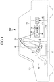
- FIG. 1 is a configuration diagram schematically illustrating an example of a seatbelt apparatus 100.
- the seatbelt apparatus 100 is mounted on a vehicle 13 such as a car.
- the seatbelt apparatus 100 includes, for example, a seatbelt 2, a seatbelt winding apparatus 16, a shoulder anchor 3, a tongue 4, and a buckle 5.
- the seatbelt winding apparatus 16 includes a retractor 6 and a control device 1.
- the vehicle 13 is provided with an openable and closable door 12. For example, the door 12 is for a user 9 to get on and off the vehicle 13.
- the seatbelt 2 is an example of a belt-shaped member for restraining the user 9 sitting on a seat 11 of the vehicle 13.
- the seatbelt 2 is wound up by the retractor 6 and can be pulled out from the retractor 6.
- An end of the seatbelt 2 is connected to the retractor 6, and the other end of the seatbelt 2 is fixed to the car body, a pretensioner device, or the seat 11.
- Seatbelts are also called webbings.
- the retractor 6 is an example of a winding device for enabling winding up and pulling out the seatbelt 2.
- the retractor 6 is fixed to the car body in a close distance from the seat 11.
- the retractor 6 restricts the seatbelt 2 not to be pulled out from the retractor 6, for example, at an emergency where deceleration that is equal to or greater than a predetermined value is imposed or is likely to be imposed on the vehicle 13.
- the retractor 6 may perform an action of winding up the seatbelt 2 at a time where deceleration that is equal to or greater than a predetermined value is imposed or is likely to be imposed on the vehicle 13, in order to remove slack in the seatbelt 2 or to sustain a posture of the user 9.
- An emergency where deceleration that is equal to or greater than a predetermined value is imposed on the vehicle 13 is, for example, a time of activating a sudden brake, to decelerate the vehicle 13 at deceleration that is equal to or greater than a predetermined value through an automatic braking operation or a manual braking operation of a driver, and a time of activating an automatic brake, to automatically decelerate the vehicle 13 at deceleration that is equal to or greater than a predetermined value without a braking operation of a driver.
- Examples of an emergency where deceleration that is equal to or greater than a predetermined value is likely to be imposed on the vehicle 13 include a time of determining that there is a probability of the vehicle 13 colliding.
- the retractor 6 includes, for example, a belt-reel 8 and a motor 7, which winds up the seatbelt 2 using the belt-reel 8.
- the motor 7 positively rotates the belt-reel 8 in a winding direction to wind up the seatbelt 2 into the belt-reel 8 of the retractor 6, and rotates the belt-reel 8 in the opposite direction of the winding direction (i.e. reverse rotation), so as to release connection of the belt-reel 8 and the motor 7.
- the retractor 6 is capable of, for example, properly reducing slack in the seatbelt 2. Furthermore, by use of the motor 7, which can wind up the seatbelt 2, the retractor 6 is capable of, for example, automatically housing the seatbelt 2 in the retractor 6 and assisting the user 9 to manually house the seatbelt 2 in the retractor 6 by hand.
- the shoulder anchor 3 is an example of a guide member for guiding the seatbelt 2 pulled out from the retractor 6 towards the shoulder of a passenger.
- the tongue 4 is an example of a slidable member attached to the seatbelt 2, which is guided by the shoulder anchor 3.
- the buckle 5 is an example of an engaging member, to which the tongue 4 is attachable and detachable.
- the buckle 5 is fixed to the floor of the car body or to the seat 11.
- the tongue 4 When the seatbelt 2 is not fastened for a passenger, i.e., in an unfastened state, the tongue 4 is not engaged with the buckle 5 and the entire length of the seatbelt 2 (specifically, the length of the seatbelt 2 that can be naturally wound up by the retractor 6) is wound up by the retractor 6. Contrarily, when the seatbelt 2 is fastened for a passenger, i.e., in a fastened state, the seatbelt 2 is pulled out from the retractor 6, as illustrated in FIG. 1 . Further, the tongue 4 is engaged with the buckle 5, and the seatbelt 2 is wound up by the retractor 6 to reduce slack in the seatbelt 2, such that the seatbelt 2 is fastened for the passenger.
- the seatbelt 2 When the tongue 4 is engaged with the buckle 5, i.e., when the seatbelt 2 is fastened for a passenger, the seatbelt 2 can be freely pulled out in a normal pullout speed, as far as being in an ordinary state where deceleration that is equal to or greater than a predetermined value is not imposed on the vehicle 13. In addition, when the seatbelt 2 is released from a force for pulling out that is imposed in a direction of pulling out, unnecessary length of the pulled-out seatbelt 2 is wound up by the retractor 6.
- the retractor 6 locks up or winds up the seatbelt 2 to restrict the seatbelt 2 not to be pulled out from the retractor 6, in order to strengthen restraining power of the seatbelt 2 upon the passenger.
- the control device 1 is an example of a computer device for controlling the winding action of the retractor 6 to wind up the seatbelt 2 by use of the motor 7, for example, by applying a motor current to the motor 7 so as to drive the motor 7 of the retractor 6.
- Examples of the control device 1 include an electric control unit (what is called an engine control unit (ECU)) for controlling a seatbelt, etc.
- ECU engine control unit
- the control device 1 includes a control-circuit 15 that obtains a signal indicating a state of the vehicle 13, from at least one of another computer device, a sensor, and a switch, which are mounted on the vehicle 13, via a signal line 10.
- Examples of the signal line 10 include a wire harness that conveys a signal indicative of a high-level or a low-level, and a communication line that conveys data in a predetermined communication standard, such as a controller area network (CAN).
- Examples of the control-circuit 15 include a microcomputer provided with a central processing unit (CPU), a processor, etc.
- Examples of a signal indicating a state of the vehicle 13 include a vehicle-speed signal that indicates a state of speed of the vehicle 13, a brake-activating signal that is indicative of an activation of a sudden brake or an automatic brake of the vehicle 13, a collision-predicting signal that indicates that there is a possibility of collision of the vehicle 13, etc.
- the brake-activating signal that is indicative of an activation of a sudden brake or an automatic brake of the vehicle 13 is output, for example, from a braking-control device that controls braking of the vehicle 13.
- the collision-predicting signal that indicates that there is a possibility of collision of the vehicle 13 is output, for example, from a collision-predicting device that predicts collision of the vehicle 13.
- the braking-control device that controls braking of the vehicle 13 may activate an automatic brake of the vehicle 13 upon detection of a collision-predicting signal, and then generate/output a brake-activating signal that is indicative of an activation of an automatic brake of the vehicle 13.
- the control device 1 includes a drive-circuit 14 that applies, to the motor 7, a motor current (hereinafter referred to as a "motor current I" as well) for driving the motor 7.
- the drive-circuit 14 adjusts a current direction and an amount of the motor current I, based on a driving signal (e.g. a driving signal of pulse-width modulation) provided from the control-circuit 15.
- Examples of the drive-circuit 14 include an H-bridge circuit having four switching elements, etc.
- the drive-circuit 14 of the control device 1 causes the motor current I to flow in a winding-current direction (hereinafter referred to as a "winding direction D1" as well), so as to drive the motor 7 to generate force to wind up the seatbelt 2 by use of the belt-reel 8 of the retractor 6, in order to wind up the seatbelt 2.
- the drive-circuit 14 of the control device 1 causes the motor current I to flow in an opposite direction of the winding direction D1 (hereinafter referred to as a "reverse direction D2" as well), so as to release the connection of the belt-reel 8 and the motor 7.
- the control-circuit 15 of the control device 1 upon detecting a brake-activating signal that is indicative of an activation of a sudden brake or an automatic brake of the vehicle 13, operates the drive-circuit 14 of the control device 1 to cause the motor current I to start flowing in the winding direction D1. For example, upon detecting a collision-predicting signal that indicates that there is a possibility of collision of the vehicle 13, the control-circuit 15 of the control device 1 may operate the drive-circuit 14 of the control device 1 to cause the motor current I to start flowing in the winding direction D1.
- the drive-circuit 14 of the control device 1 upon detecting at least one of a brake-activating signal that is indicative of an activation of a sudden brake or an automatic brake and a collision-predicting signal that indicates that there is a possibility of collision, the drive-circuit 14 of the control device 1 causes the motor current I to start flowing in the winding direction D1.
- FIG. 2 is a waveform diagram illustrating an example of changing a current value of the motor current I.
- magnitude of the motor current I is indicated by an arbitrary unit along the vertical axis, and time is indicated by a given unit along the horizontal axis.
- a positive value is indicative of a current value of the motor current I that flows in the winding direction D1;
- a negative value is indicative of a current value of the motor current I that flows in the reverse direction D2;
- 0 is indicative of a state where the motor current I does not flow either in the winding direction D1 or in the reverse direction D2.
- a winding current i1 is indicative of the motor current I in a first current value, which is required to wind up the seatbelt 2.
- a first sustaining current i2 is indicative of the motor current I in a second current value, which is required to sustain tension of the seatbelt 2.
- a second sustaining current i3 is indicative of the motor current I in a third current value, which is required to sustain tension of the seatbelt 2. The third current value is lower than the second current value, and the second current value is lower than the first current value.
- Each of the winding current i1, the first sustaining current i2, and the second sustaining current i3 is the motor current I that flows in the winding direction D1.
- the first sustaining current i2 is a constant current having a constant second current value.
- a releasing current i4 is indicative of the motor current I in a fourth current value, which is required to release tension of the seatbelt 2 caused by the motor 7 through a clutch of the retractor 6.
- the releasing current i4 is indicative of the motor current I that flows in the reverse direction D2.
- currents expressed by the reference signs i1 through i4 and the relations of the currents with the reference signs i1 through i4 are the same as in FIG. 2 .
- the control-circuit 15 operates the drive-circuit 14 to raise a current value of the motor current I that flows in the winding direction D1 to the first current value, which is required to wind up the seatbelt 2.
- the control-circuit 15 may operate the drive-circuit 14 to raise a current value of the motor current I that flows in the winding direction D1 to the first current value, which is required to wind up the seatbelt 2.
- the first current value may or may not be a constant value.
- the drive-circuit 14 applies the motor current I at the first current value (i.e. the winding current i1) for a winding time T1.
- the winding time T1 is, for example, an elapsed time from the timing t1 to the timing t2.
- the winding time T1 may be a preset fixed time and may be a variable time until a detection that tension of the seatbelt 2 is equal to or more than a predetermined value.
- the control-circuit 15 of the control device 1 operates the drive-circuit 14 to lower the current value of the motor current I that flows in the winding direction D1 from the first current value, which is required to wind up the seatbelt 2, to the second current value, which is required to sustain tension of the seatbelt 2.
- the control-circuit 15 operates the drive-circuit 14 to change the motor current I from the winding current i1 to the first sustaining current i2.
- the control-circuit 15 of the control device 1 is provided with, for example, a counter or a counter-function for counting a current-conducting duration (hereinafter referred to as a "current-conducting duration Tc" as well) during which the motor current I flows in the winding direction D1.
- the current-conducting duration Tc is an elapsed time from the timing t1, at which the motor current I starts to flow in the winding direction D1.
- the control-circuit 15 is capable of precisely counting the current-conducting duration Tc from when the motor current I starts to flow in the winding direction D1.
- the counter or the counter-function of the control-circuit 15 is an example of a measurement-unit (or a measurement-function) for measuring the current-conducting duration Tc, based on, for example, time information that is obtained by the control device 1.
- control-circuit 15 may start counting the current-conducting duration Tc upon detecting an activation of a sudden brake or an automatic brake of the vehicle 13, based on a brake-activating signal that is indicative of an activation of a sudden brake or an automatic brake of the vehicle 13.
- control-circuit 15 is capable of precisely counting the current-conducting duration Tc from when the motor current I starts to flow in the winding direction D1 in response to an activation of a sudden brake or an automatic brake.
- control-circuit 15 may start counting the current-conducting duration Tc upon detecting a possibility of collision of the vehicle 13, based on a collision-predicting signal that indicates that there is a possibility of collision of the vehicle 13.
- a sudden brake or an automatic brake of the vehicle 13 is activated in response to a collision-predicting signal.
- the control-circuit 15 is capable of precisely counting the current-conducting duration Tc from when the motor current I starts to flow in the winding direction D1.
- the control-circuit 15 promptly changes the motor current I from the first sustaining current i2, which flows in the winding direction D1, to the releasing current i4, which flows in the reverse direction D2, and then causes the releasing current i4 to flow for a releasing time T4. Then, after a completion of a sudden brake or an automatic brake, the user 9 is allowed to easily pull out the seatbelt 2 from the retractor 6.
- the control-circuit 15 further lowers a current value of the motor current I, which flows in the winding direction D1, from the second current value.
- the control-circuit 15 operates the drive-circuit 14 to change the motor current I from the first sustaining current i2 to second sustaining current i3 at a timing t3 prior to changing the motor current I to the releasing current i4.
- the control-circuit 15 estimates that the vehicle 13 is in a situation where deceleration that should be generated for the vehicle 13 by sudden braking, etc., under normal circumstances is not actually generated to the expected degree, due to a slip, etc. Therefore, for example, even in a case where the vehicle 13 is slipping, the control-circuit 15 is capable of preventing heat of the motor 7 and the drive-circuit 14, compared to a case where the motor current I in the second current value flows continuously, because the control-circuit 15 further lowers a current value of the motor current I, which flows in the winding direction D1, from the second current value.
- control-circuit 15 is capable of preventing heat of the motor 7 and the drive-circuit 14, because, in a case where the current-conducting duration Tc has attained the set time T2, the control-circuit 15 further lowers a current value of the motor current I, which flows in the winding direction D1, from the second current value.
- the control-circuit 15 of the control device 1 may adjust the length of the set time T2 in accordance with vehicle-speed at a moment of causing the motor current I to start flowing in the winding direction D1.
- a braking time Tb which is from activating a sudden brake or an automatic brake to completing the sudden brake or automatic brake (i.e. until the vehicle 13 stops), varies.
- the set time T2 may be adjusted to a suitable value, by adjusting the length of the set time T2 in accordance with vehicle-speed at a moment of causing the motor current I to start flowing in the winding direction D1.
- the control-circuit 15 sets the set time T2 to a theoretical value (or design value) of a braking time Tb, which is theoretically calculated in accordance with vehicle-speed of a moment of causing the motor current I to start flowing in the winding direction D1 (i.e. at a moment of activating a sudden brake or an automatic brake). Therefore, the control-circuit 15 is capable of precisely estimating whether or not the vehicle 13 is in a situation where deceleration that should be generated for the vehicle 13 by sudden braking, etc., under normal circumstances is not actually generated to the expected degree, due to a slip, etc.
- control-circuit 15 of the control device 1 may adjust the length of the set time T2 in accordance with vehicle-speed at a moment of detecting a collision-predicting signal that indicates that there is a possibility of collision of the vehicle.
- the control-circuit 15 of the control device 1 operates the drive-circuit 14 to continue causing the motor current I to flow in the winding direction D1 until the current-conducting duration Tc has attained a second set time T3.
- the second set time T3 is longer than the first set time T2. Because of the second set time T3 during which tension of the seatbelt 2 is comparatively sustained, the seatbelt 2 is prevented from being pulled out by passenger inertia.
- the control-circuit 15 of the control device 1 may adjust the length of the second set time T3, for example, in accordance with vehicle-speed at a moment of causing the motor current I to flow in the winding direction D1.
- the control-circuit 15 of the control device 1 operates the drive-circuit 14 to maintain a current value of the motor current I, which flows in the winding direction D1, equal to or lower than the second current value, for example, until the current-conducting duration Tc has attained the second set time T3.
- the user 9 may feel less uncomfortable because significant change of tension of the seatbelt 2 is prevented, as the motor current I, which flows in the winding direction D1, is prevented from exceeding the second current value.
- the control-circuit 15 of the control device 1 causes the releasing current i4 to flow for the releasing time T4 in a case where the current-conducting duration Tc has attained the second set time T3. Then, after a completion of a sudden brake or an automatic brake, the user 9 is allowed to easily pull out the seatbelt 2 from the retractor 6.
- the control-circuit 15 of the control device 1 may operate the drive-circuit 14 to continue causing the second sustaining current i3 to flow, for example, until detecting a completion of a brake of the vehicle 13. In this case, because tension of the seatbelt 2 is comparatively sustained, the seatbelt 2 is prevented from being pulled out by passenger inertia.
- the control-circuit 15 of the control device 1 may operate the drive-circuit 14 to maintain a current value of the motor current I, which flows in the winding direction D1, equal to or lower than the second current value, for example, until detecting a completion of a brake of the vehicle 13.
- the user 9 may feel less uncomfortable because significant change of tension of the seatbelt 2 is prevented, as the motor current I, which flows in the winding direction D1, is prevented from exceeding the second current value.
- the control-circuit 15 of the control device 1 causes the releasing current i4 to flow for the releasing time T4, for example, upon detecting a completion of a braking action of the vehicle 13. Then, after a completion of a sudden brake or an automatic brake, the user 9 is allowed to easily pull out the seatbelt 2 from the retractor 6.
- FIG. 3 is a waveform diagram illustrating an example of changing a current value of the motor current I.
- magnitude of the motor current I is indicated by a given unit along the vertical axis
- time is indicated by a given unit along the horizontal axis.
- the control-circuit 15 of the control device 1 may decrease a current value of the motor current I, which flows in the winding direction D1, gradually from the second current value that is required to sustain tension of the seatbelt 2.
- the control-circuit 15 changes from a first sustaining current i2, which is constant, to a second sustaining current i3, which is gradually decreased in a linear manner.
- the user 9 may feel less uncomfortable because force to sustain tension of the seatbelt 2 is reduced smoothly.
- FIG. 4 is a waveform diagram illustrating an example of changing a current value of the motor current I.
- magnitude of the motor current I is indicated by a given unit along the vertical axis
- time is indicated by a given unit along the horizontal axis.
- the control-circuit 15 of the control device 1 may change from a first sustaining current i2, which is constant, to a second sustaining current i3, which is gradually decreased in a curve.
- the control-circuit 15 decreases either as a second sustaining current i31 or as a second sustaining current i32 gradually in a curve.
- the control-circuit 15 changes a first sustaining current i2, which is constant, into either a second sustaining current i31 or a second sustaining current i32.
- a first sustaining current i2 which is constant
- FIG. 5 is a waveform diagram illustrating an example of changing a current value of the motor current I.
- magnitude of the motor current I is indicated by a given unit along the vertical axis
- time is indicated by a given unit along the horizontal axis.
- the control-circuit 15 of the control device 1 may change from a first sustaining current i2, which is constant, to a second sustaining current i3, which is gradually decreased step by step.
- the control-circuit 15 gradually decreases the second sustaining current i3 step by step.
- the control-circuit 15 changes from the first sustaining current i2, which is constant, to the second sustaining current i3, which is gradually decreased step by step.
- the user 9 may feel less uncomfortable because force to sustain tension of the seatbelt 2 is reduced smoothly.
- heat of a motor, etc. can be prevented because, when a current-conducting duration has attained a set time, a current value of a motor current that flows in a winding-current direction is further lowered from a current value (i.e. a second current value) required to sustain tension of a seatbelt.
Landscapes
- Engineering & Computer Science (AREA)
- Mechanical Engineering (AREA)
- Automation & Control Theory (AREA)
- Automotive Seat Belt Assembly (AREA)
Abstract
Description
- The present invention relates to seatbelt winding apparatuses and seatbelt apparatuses.
- Conventionally, there has been a seatbelt winding apparatus, which applies high current for winding up a seatbelt to a motor, in a case where there is a possibility of collision, etc., and then continues applying a sustaining current that is high enough to prevent tension of the seatbelt from being slack (see, for example, Patent document 1).
- [Patent document 1] Japanese Unexamined Patent Application Publication No.
2003-312443 - However, in a situation where deceleration of a vehicle is relatively low (for example, when a vehicle is slipping, etc.), there is a case that a motor, etc., produces heat because the sustaining current, which is high enough to prevent tension of a seatbelt from being slack, may be applied for a long period of time.
- Therefore, one object of the present invention is to provide a seatbelt winding apparatus and a seatbelt apparatus that is capable of preventing heat of a motor, etc.
- One proposal is to provide a seatbelt winding apparatus including: a motor; and a control device configured to generate a flow of motor current in a winding-current direction that drives the motor to generate force to wind up a seatbelt, and configured to lower a current value of the motor current flowing in the winding-current direction from a first current value to a second current value, the first current value being required to wind up the seatbelt and the second current value being required to sustain tension of the seatbelt. The control device measures a current-conducting duration during which the motor current flows in the winding-current direction, and, upon the current-conducting duration having attained a set time, the control device further lowers the current value of the motor current flowing in the winding-current direction from the second current value.
- Another proposal is to provide a seatbelt winding apparatus including: a motor; and a control device configured to generate a flow of motor current in a winding-current direction that drives the motor to generate force to wind up a seatbelt, and configured to lower a current value of the motor current flowing in the winding-current direction from a first current value to a second current value, the first current value being required to wind up the seatbelt and the second current value being required to sustain tension of the seatbelt. The control device measures a current-conducting duration during which the motor current flows in the winding-current direction, and, in a case of not detecting a completion of a braking action of a vehicle by a time when the current-conducting duration has attained a set time, the control device further lowers the current value of the motor current flowing in the winding-current direction from the second current value.
- According to an embodiment, heat of a motor, etc., may be prevented.
-
- [
FIG. 1] FIG. 1 is a configuration diagram illustrating an example of a seatbelt apparatus; - [
FIG. 2] FIG. 2 is a waveform diagram illustrating an example of changing a current value of a motor current; - [
FIG. 3] FIG. 3 is a waveform diagram illustrating an example of changing a current value of the motor current; - [
FIG. 4] FIG. 4 is a waveform diagram illustrating an example of changing a current value of the motor current; and - [
FIG. 5] FIG. 5 is a waveform diagram illustrating an example of changing a current value of the motor current. - The following description explains embodiments of the present invention, with reference to drawings.
-
FIG. 1 is a configuration diagram schematically illustrating an example of aseatbelt apparatus 100. Theseatbelt apparatus 100 is mounted on avehicle 13 such as a car. Theseatbelt apparatus 100 includes, for example, a seatbelt 2, aseatbelt winding apparatus 16, ashoulder anchor 3, atongue 4, and abuckle 5. Theseatbelt winding apparatus 16 includes aretractor 6 and acontrol device 1. Thevehicle 13 is provided with an openable andclosable door 12. For example, thedoor 12 is for auser 9 to get on and off thevehicle 13. - The seatbelt 2 is an example of a belt-shaped member for restraining the
user 9 sitting on aseat 11 of thevehicle 13. The seatbelt 2 is wound up by theretractor 6 and can be pulled out from theretractor 6. An end of the seatbelt 2 is connected to theretractor 6, and the other end of the seatbelt 2 is fixed to the car body, a pretensioner device, or theseat 11. Seatbelts are also called webbings. - The
retractor 6 is an example of a winding device for enabling winding up and pulling out the seatbelt 2. For example, theretractor 6 is fixed to the car body in a close distance from theseat 11. Theretractor 6 restricts the seatbelt 2 not to be pulled out from theretractor 6, for example, at an emergency where deceleration that is equal to or greater than a predetermined value is imposed or is likely to be imposed on thevehicle 13. Theretractor 6 may perform an action of winding up the seatbelt 2 at a time where deceleration that is equal to or greater than a predetermined value is imposed or is likely to be imposed on thevehicle 13, in order to remove slack in the seatbelt 2 or to sustain a posture of theuser 9. - An emergency where deceleration that is equal to or greater than a predetermined value is imposed on the
vehicle 13 is, for example, a time of activating a sudden brake, to decelerate thevehicle 13 at deceleration that is equal to or greater than a predetermined value through an automatic braking operation or a manual braking operation of a driver, and a time of activating an automatic brake, to automatically decelerate thevehicle 13 at deceleration that is equal to or greater than a predetermined value without a braking operation of a driver. Examples of an emergency where deceleration that is equal to or greater than a predetermined value is likely to be imposed on thevehicle 13 include a time of determining that there is a probability of thevehicle 13 colliding. - The
retractor 6 includes, for example, a belt-reel 8 and amotor 7, which winds up the seatbelt 2 using the belt-reel 8. For example, themotor 7 positively rotates the belt-reel 8 in a winding direction to wind up the seatbelt 2 into the belt-reel 8 of theretractor 6, and rotates the belt-reel 8 in the opposite direction of the winding direction (i.e. reverse rotation), so as to release connection of the belt-reel 8 and themotor 7. - By use of the
motor 7, which can adjust the length of the seatbelt 2 to wind up, theretractor 6 is capable of, for example, properly reducing slack in the seatbelt 2. Furthermore, by use of themotor 7, which can wind up the seatbelt 2, theretractor 6 is capable of, for example, automatically housing the seatbelt 2 in theretractor 6 and assisting theuser 9 to manually house the seatbelt 2 in theretractor 6 by hand. - The
shoulder anchor 3 is an example of a guide member for guiding the seatbelt 2 pulled out from theretractor 6 towards the shoulder of a passenger. - The
tongue 4 is an example of a slidable member attached to the seatbelt 2, which is guided by theshoulder anchor 3. - The
buckle 5 is an example of an engaging member, to which thetongue 4 is attachable and detachable. For example, thebuckle 5 is fixed to the floor of the car body or to theseat 11. - When the seatbelt 2 is not fastened for a passenger, i.e., in an unfastened state, the
tongue 4 is not engaged with thebuckle 5 and the entire length of the seatbelt 2 (specifically, the length of the seatbelt 2 that can be naturally wound up by the retractor 6) is wound up by theretractor 6. Contrarily, when the seatbelt 2 is fastened for a passenger, i.e., in a fastened state, the seatbelt 2 is pulled out from theretractor 6, as illustrated inFIG. 1 . Further, thetongue 4 is engaged with thebuckle 5, and the seatbelt 2 is wound up by theretractor 6 to reduce slack in the seatbelt 2, such that the seatbelt 2 is fastened for the passenger. - When the
tongue 4 is engaged with thebuckle 5, i.e., when the seatbelt 2 is fastened for a passenger, the seatbelt 2 can be freely pulled out in a normal pullout speed, as far as being in an ordinary state where deceleration that is equal to or greater than a predetermined value is not imposed on thevehicle 13. In addition, when the seatbelt 2 is released from a force for pulling out that is imposed in a direction of pulling out, unnecessary length of the pulled-out seatbelt 2 is wound up by theretractor 6. - In an emergency where deceleration that is equal to or greater than a predetermined value is imposed or is likely to be imposed on the
vehicle 13 when thetongue 4 is engaged with thebuckle 5, i.e., when the seatbelt 2 is fastened for a passenger, theretractor 6 locks up or winds up the seatbelt 2 to restrict the seatbelt 2 not to be pulled out from theretractor 6, in order to strengthen restraining power of the seatbelt 2 upon the passenger. - The
control device 1 is an example of a computer device for controlling the winding action of theretractor 6 to wind up the seatbelt 2 by use of themotor 7, for example, by applying a motor current to themotor 7 so as to drive themotor 7 of theretractor 6. Examples of thecontrol device 1 include an electric control unit (what is called an engine control unit (ECU)) for controlling a seatbelt, etc. - The
control device 1 includes a control-circuit 15 that obtains a signal indicating a state of thevehicle 13, from at least one of another computer device, a sensor, and a switch, which are mounted on thevehicle 13, via asignal line 10. Examples of thesignal line 10 include a wire harness that conveys a signal indicative of a high-level or a low-level, and a communication line that conveys data in a predetermined communication standard, such as a controller area network (CAN). Examples of the control-circuit 15 include a microcomputer provided with a central processing unit (CPU), a processor, etc. Examples of a signal indicating a state of thevehicle 13 include a vehicle-speed signal that indicates a state of speed of thevehicle 13, a brake-activating signal that is indicative of an activation of a sudden brake or an automatic brake of thevehicle 13, a collision-predicting signal that indicates that there is a possibility of collision of thevehicle 13, etc. - The brake-activating signal that is indicative of an activation of a sudden brake or an automatic brake of the
vehicle 13 is output, for example, from a braking-control device that controls braking of thevehicle 13. The collision-predicting signal that indicates that there is a possibility of collision of thevehicle 13 is output, for example, from a collision-predicting device that predicts collision of thevehicle 13. For example, the braking-control device that controls braking of thevehicle 13 may activate an automatic brake of thevehicle 13 upon detection of a collision-predicting signal, and then generate/output a brake-activating signal that is indicative of an activation of an automatic brake of thevehicle 13. - The
control device 1 includes a drive-circuit 14 that applies, to themotor 7, a motor current (hereinafter referred to as a "motor current I" as well) for driving themotor 7. The drive-circuit 14 adjusts a current direction and an amount of the motor current I, based on a driving signal (e.g. a driving signal of pulse-width modulation) provided from the control-circuit 15. Examples of the drive-circuit 14 include an H-bridge circuit having four switching elements, etc. - For example, the drive-
circuit 14 of thecontrol device 1 causes the motor current I to flow in a winding-current direction (hereinafter referred to as a "winding direction D1" as well), so as to drive themotor 7 to generate force to wind up the seatbelt 2 by use of the belt-reel 8 of theretractor 6, in order to wind up the seatbelt 2. Contrarily, for example, the drive-circuit 14 of thecontrol device 1 causes the motor current I to flow in an opposite direction of the winding direction D1 (hereinafter referred to as a "reverse direction D2" as well), so as to release the connection of the belt-reel 8 and themotor 7. - For example, upon detecting a brake-activating signal that is indicative of an activation of a sudden brake or an automatic brake of the
vehicle 13, the control-circuit 15 of thecontrol device 1 operates the drive-circuit 14 of thecontrol device 1 to cause the motor current I to start flowing in the winding direction D1. For example, upon detecting a collision-predicting signal that indicates that there is a possibility of collision of thevehicle 13, the control-circuit 15 of thecontrol device 1 may operate the drive-circuit 14 of thecontrol device 1 to cause the motor current I to start flowing in the winding direction D1. As described above, for example, upon detecting at least one of a brake-activating signal that is indicative of an activation of a sudden brake or an automatic brake and a collision-predicting signal that indicates that there is a possibility of collision, the drive-circuit 14 of thecontrol device 1 causes the motor current I to start flowing in the winding direction D1. -
FIG. 2 is a waveform diagram illustrating an example of changing a current value of the motor current I. InFIG. 2 , magnitude of the motor current I is indicated by an arbitrary unit along the vertical axis, and time is indicated by a given unit along the horizontal axis. InFIG. 2 , a positive value is indicative of a current value of the motor current I that flows in the winding direction D1; a negative value is indicative of a current value of the motor current I that flows in the reverse direction D2; and 0 is indicative of a state where the motor current I does not flow either in the winding direction D1 or in the reverse direction D2. - A winding current i1 is indicative of the motor current I in a first current value, which is required to wind up the seatbelt 2. A first sustaining current i2 is indicative of the motor current I in a second current value, which is required to sustain tension of the seatbelt 2. A second sustaining current i3 is indicative of the motor current I in a third current value, which is required to sustain tension of the seatbelt 2. The third current value is lower than the second current value, and the second current value is lower than the first current value. Each of the winding current i1, the first sustaining current i2, and the second sustaining current i3 is the motor current I that flows in the winding direction D1. The first sustaining current i2 is a constant current having a constant second current value. A releasing current i4 is indicative of the motor current I in a fourth current value, which is required to release tension of the seatbelt 2 caused by the
motor 7 through a clutch of theretractor 6. The releasing current i4 is indicative of the motor current I that flows in the reverse direction D2. In later-describedFIGS. 3 through 5 , currents expressed by the reference signs i1 through i4 and the relations of the currents with the reference signs i1 through i4 are the same as inFIG. 2 . - For example, in a case of detecting a brake-activating signal that is indicative of an activation of a sudden brake or an automatic brake at a timing t1, the control-
circuit 15 operates the drive-circuit 14 to raise a current value of the motor current I that flows in the winding direction D1 to the first current value, which is required to wind up the seatbelt 2. For example, in a case of detecting a collision-predicting signal that indicates that there is a possibility of collision of thevehicle 13 at the timing t1, the control-circuit 15 may operate the drive-circuit 14 to raise a current value of the motor current I that flows in the winding direction D1 to the first current value, which is required to wind up the seatbelt 2. The first current value may or may not be a constant value. The drive-circuit 14 applies the motor current I at the first current value (i.e. the winding current i1) for a winding time T1. - The winding time T1 is, for example, an elapsed time from the timing t1 to the timing t2. The winding time T1 may be a preset fixed time and may be a variable time until a detection that tension of the seatbelt 2 is equal to or more than a predetermined value.
- For example, after the winding time T1 passes, the control-
circuit 15 of thecontrol device 1 operates the drive-circuit 14 to lower the current value of the motor current I that flows in the winding direction D1 from the first current value, which is required to wind up the seatbelt 2, to the second current value, which is required to sustain tension of the seatbelt 2. In other words, the control-circuit 15 operates the drive-circuit 14 to change the motor current I from the winding current i1 to the first sustaining current i2. - The control-
circuit 15 of thecontrol device 1 is provided with, for example, a counter or a counter-function for counting a current-conducting duration (hereinafter referred to as a "current-conducting duration Tc" as well) during which the motor current I flows in the winding direction D1. For example, the current-conducting duration Tc is an elapsed time from the timing t1, at which the motor current I starts to flow in the winding direction D1. By means of the counter or the counter-function, the control-circuit 15 is capable of precisely counting the current-conducting duration Tc from when the motor current I starts to flow in the winding direction D1. The counter or the counter-function of the control-circuit 15 is an example of a measurement-unit (or a measurement-function) for measuring the current-conducting duration Tc, based on, for example, time information that is obtained by thecontrol device 1. - For example, the control-
circuit 15 may start counting the current-conducting duration Tc upon detecting an activation of a sudden brake or an automatic brake of thevehicle 13, based on a brake-activating signal that is indicative of an activation of a sudden brake or an automatic brake of thevehicle 13. In this case, the control-circuit 15 is capable of precisely counting the current-conducting duration Tc from when the motor current I starts to flow in the winding direction D1 in response to an activation of a sudden brake or an automatic brake. - For example, the control-
circuit 15 may start counting the current-conducting duration Tc upon detecting a possibility of collision of thevehicle 13, based on a collision-predicting signal that indicates that there is a possibility of collision of thevehicle 13. In one embodiment, a sudden brake or an automatic brake of thevehicle 13 is activated in response to a collision-predicting signal. In this embodiment, also for the case of the control-circuit 15 starting counting of the current-conducting duration Tc in response to a collision-predicting signal, the control-circuit 15 is capable of precisely counting the current-conducting duration Tc from when the motor current I starts to flow in the winding direction D1. - In a case of having detected a completion of a sudden brake or an automatic brake of the
vehicle 13 after passing the winding time T1 and before the current-conducting duration Tc would have attained a set time T2, the control-circuit 15 promptly changes the motor current I from the first sustaining current i2, which flows in the winding direction D1, to the releasing current i4, which flows in the reverse direction D2, and then causes the releasing current i4 to flow for a releasing time T4. Then, after a completion of a sudden brake or an automatic brake, theuser 9 is allowed to easily pull out the seatbelt 2 from theretractor 6. - Contrarily, in a case of not having detected a completion of a sudden brake or an automatic brake of the
vehicle 13 after passing the winding time T1 and before the current-conducting duration Tc would have attained the set time T2, the control-circuit 15 further lowers a current value of the motor current I, which flows in the winding direction D1, from the second current value. In other words, the control-circuit 15 operates the drive-circuit 14 to change the motor current I from the first sustaining current i2 to second sustaining current i3 at a timing t3 prior to changing the motor current I to the releasing current i4. - In a case where the current-conducting duration Tc has attained the set time T2, the control-
circuit 15 estimates that thevehicle 13 is in a situation where deceleration that should be generated for thevehicle 13 by sudden braking, etc., under normal circumstances is not actually generated to the expected degree, due to a slip, etc. Therefore, for example, even in a case where thevehicle 13 is slipping, the control-circuit 15 is capable of preventing heat of themotor 7 and the drive-circuit 14, compared to a case where the motor current I in the second current value flows continuously, because the control-circuit 15 further lowers a current value of the motor current I, which flows in the winding direction D1, from the second current value. Furthermore, even without a sensor for detecting deceleration of thevehicle 13, the control-circuit 15 is capable of preventing heat of themotor 7 and the drive-circuit 14, because, in a case where the current-conducting duration Tc has attained the set time T2, the control-circuit 15 further lowers a current value of the motor current I, which flows in the winding direction D1, from the second current value. - For example, the control-
circuit 15 of thecontrol device 1 may adjust the length of the set time T2 in accordance with vehicle-speed at a moment of causing the motor current I to start flowing in the winding direction D1. Depending on vehicle-speed at a moment of activating a sudden brake or an automatic brake, a braking time Tb, which is from activating a sudden brake or an automatic brake to completing the sudden brake or automatic brake (i.e. until thevehicle 13 stops), varies. Furthermore, causing the motor current I to start flowing in the winding direction D1 and activating a sudden brake or an automatic brake are performed almost at the same timing (i.e. the timing t1). Therefore, the set time T2 may be adjusted to a suitable value, by adjusting the length of the set time T2 in accordance with vehicle-speed at a moment of causing the motor current I to start flowing in the winding direction D1. - For example, the control-
circuit 15 sets the set time T2 to a theoretical value (or design value) of a braking time Tb, which is theoretically calculated in accordance with vehicle-speed of a moment of causing the motor current I to start flowing in the winding direction D1 (i.e. at a moment of activating a sudden brake or an automatic brake). Therefore, the control-circuit 15 is capable of precisely estimating whether or not thevehicle 13 is in a situation where deceleration that should be generated for thevehicle 13 by sudden braking, etc., under normal circumstances is not actually generated to the expected degree, due to a slip, etc. - Note that the control-
circuit 15 of thecontrol device 1 may adjust the length of the set time T2 in accordance with vehicle-speed at a moment of detecting a collision-predicting signal that indicates that there is a possibility of collision of the vehicle. - For example, the control-
circuit 15 of thecontrol device 1 operates the drive-circuit 14 to continue causing the motor current I to flow in the winding direction D1 until the current-conducting duration Tc has attained a second set time T3. The second set time T3 is longer than the first set time T2. Because of the second set time T3 during which tension of the seatbelt 2 is comparatively sustained, the seatbelt 2 is prevented from being pulled out by passenger inertia. Similarly to the set time T2, the control-circuit 15 of thecontrol device 1 may adjust the length of the second set time T3, for example, in accordance with vehicle-speed at a moment of causing the motor current I to flow in the winding direction D1. - The control-
circuit 15 of thecontrol device 1 operates the drive-circuit 14 to maintain a current value of the motor current I, which flows in the winding direction D1, equal to or lower than the second current value, for example, until the current-conducting duration Tc has attained the second set time T3. Thus, theuser 9 may feel less uncomfortable because significant change of tension of the seatbelt 2 is prevented, as the motor current I, which flows in the winding direction D1, is prevented from exceeding the second current value. - The control-
circuit 15 of thecontrol device 1 causes the releasing current i4 to flow for the releasing time T4 in a case where the current-conducting duration Tc has attained the second set time T3. Then, after a completion of a sudden brake or an automatic brake, theuser 9 is allowed to easily pull out the seatbelt 2 from theretractor 6. - The control-
circuit 15 of thecontrol device 1 may operate the drive-circuit 14 to continue causing the second sustaining current i3 to flow, for example, until detecting a completion of a brake of thevehicle 13. In this case, because tension of the seatbelt 2 is comparatively sustained, the seatbelt 2 is prevented from being pulled out by passenger inertia. - The control-
circuit 15 of thecontrol device 1 may operate the drive-circuit 14 to maintain a current value of the motor current I, which flows in the winding direction D1, equal to or lower than the second current value, for example, until detecting a completion of a brake of thevehicle 13. In this case, theuser 9 may feel less uncomfortable because significant change of tension of the seatbelt 2 is prevented, as the motor current I, which flows in the winding direction D1, is prevented from exceeding the second current value. - The control-
circuit 15 of thecontrol device 1 causes the releasing current i4 to flow for the releasing time T4, for example, upon detecting a completion of a braking action of thevehicle 13. Then, after a completion of a sudden brake or an automatic brake, theuser 9 is allowed to easily pull out the seatbelt 2 from theretractor 6. -
FIG. 3 is a waveform diagram illustrating an example of changing a current value of the motor current I. InFIG. 3 , magnitude of the motor current I is indicated by a given unit along the vertical axis, and time is indicated by a given unit along the horizontal axis. The control-circuit 15 of thecontrol device 1 may decrease a current value of the motor current I, which flows in the winding direction D1, gradually from the second current value that is required to sustain tension of the seatbelt 2. For example, as illustrated inFIG. 3 , the control-circuit 15 changes from a first sustaining current i2, which is constant, to a second sustaining current i3, which is gradually decreased in a linear manner. Thus, theuser 9 may feel less uncomfortable because force to sustain tension of the seatbelt 2 is reduced smoothly. -
FIG. 4 is a waveform diagram illustrating an example of changing a current value of the motor current I. InFIG. 4 , magnitude of the motor current I is indicated by a given unit along the vertical axis, and time is indicated by a given unit along the horizontal axis. The control-circuit 15 of thecontrol device 1 may change from a first sustaining current i2, which is constant, to a second sustaining current i3, which is gradually decreased in a curve. InFIG. 4 , the control-circuit 15 decreases either as a second sustaining current i31 or as a second sustaining current i32 gradually in a curve. The control-circuit 15 changes a first sustaining current i2, which is constant, into either a second sustaining current i31 or a second sustaining current i32. Thus, theuser 9 may feel less uncomfortable because force to sustain tension of the seatbelt 2 is reduced smoothly. -
FIG. 5 is a waveform diagram illustrating an example of changing a current value of the motor current I. InFIG. 5 , magnitude of the motor current I is indicated by a given unit along the vertical axis, and time is indicated by a given unit along the horizontal axis. The control-circuit 15 of thecontrol device 1 may change from a first sustaining current i2, which is constant, to a second sustaining current i3, which is gradually decreased step by step. InFIG. 5 , the control-circuit 15 gradually decreases the second sustaining current i3 step by step. The control-circuit 15 changes from the first sustaining current i2, which is constant, to the second sustaining current i3, which is gradually decreased step by step. Thus, theuser 9 may feel less uncomfortable because force to sustain tension of the seatbelt 2 is reduced smoothly. - Note that current value of the motor current I at timing t4 in each of the waveform diagrams of
FIGS. 2 through 5 cannot be negative value. - According to an embodiment, heat of a motor, etc., can be prevented because, when a current-conducting duration has attained a set time, a current value of a motor current that flows in a winding-current direction is further lowered from a current value (i.e. a second current value) required to sustain tension of a seatbelt.
- Although the above description explains a seatbelt winding apparatus and a seatbelt apparatus in embodiments, the present invention is not limited to the above embodiments. Variations and modifications, such as a combination or replacement of the embodiments with a part or the entirety of another embodiment, may be made without departing from the scope of the present invention.
- The present application is based on Japanese priority application No.
2014-257801 filed on December 19, 2014 -
- 1
- control device
- 2
- seatbelt
- 3
- shoulder anchor
- 4
- tongue
- 5
- buckle
- 6
- retractor
- 7
- motor
- 8
- belt-reel
- 9
- user
- 10
- signal line
- 11
- seat
- 12
- door
- 13
- vehicle
- 14
- drive-circuit
- 15
- control-circuit
- 16
- seatbelt winding apparatus
Claims (12)
- A seatbelt winding apparatus comprising:a motor; anda control device configured to generate a flow of motor current in a winding-current direction that drives the motor to generate force to wind up a seatbelt, and configured to lower a current value of the motor current flowing in the winding-current direction from a first current value to a second current value, the first current value being required to wind up the seatbelt and the second current value being required to sustain tension of the seatbelt,wherein the control device measures a current-conducting duration during which the motor current flows in the winding-current direction, and, upon the current-conducting duration having attained a set time, the control device further lowers the current value of the motor current flowing in the winding-current direction from the second current value.
- A seatbelt winding apparatus comprising:a motor; anda control device configured to generate a flow of motor current in a winding-current direction that drives the motor to generate force to wind up a seatbelt, and configured to lower a current value of the motor current flowing in the winding-current direction from a first current value to a second current value, the first current value being required to wind up the seatbelt and the second current value being required to sustain tension of the seatbelt,wherein the control device measures a current-conducting duration during which the motor current flows in the winding-current direction, and, in a case of not detecting a completion of a braking action of a vehicle by a time when the current-conducting duration has attained a set time, the control device further lowers the current value of the motor current flowing in the winding-current direction from the second current value.
- The seatbelt winding apparatus according to claim 1 or 2, wherein the control device gradually lowers the current value of the motor current flowing in the winding-current direction from the second current value.
- The seatbelt winding apparatus according to any one of claims 1 through 3, wherein the current-conducting duration is an elapsed time from when the motor current starts flowing in the winding-current direction.
- The seatbelt winding apparatus according to claim 4, wherein the control device adjusts a length of the set time in accordance with vehicle-speed at a moment when the motor current starts flowing in the winding-current direction.
- The seatbelt winding apparatus according to any one of claims 1 through 5, wherein the control device continues causing the motor current to flow in the winding-current direction until the current-conducting duration has attained a second set time, which is longer than the set time.
- The seatbelt winding apparatus according to any one of claims 1 or 6, wherein the control device maintains the current value of the motor current flowing in the winding-current direction equal to or lower than the second current value until the current-conducting duration has attained the second set time, which is longer than the set time.
- The seatbelt winding apparatus according to claim 6 or 7, wherein the control device causes the motor current to flow in a current-direction opposite to the winding-current direction, upon the current-conducting duration having attained the second set time.
- The seatbelt winding apparatus according to any one of claims 1 through 5, wherein the control device continues causing the motor current to flow in the winding-current direction until detecting a completion of a braking action of the vehicle.
- The seatbelt winding apparatus according to any one of claims 1 through 5, wherein the control device maintains the current value of the motor current flowing in the winding-current direction equal to or lower than the second current value until detecting a completion of a braking action of the vehicle.
- The seatbelt winding apparatus according to claim 9 or 10, wherein the control device causes the motor current to flow in a current-direction opposite to the winding-current direction, upon detecting the completion of a braking action.
- A seatbelt apparatus comprising:the seatbelt winding apparatus according to any one of claims 1 through 11;the seatbelt;a guide member configured to guide the seatbelt;a tongue to which the seatbelt is attached; anda buckle to which the tongue is attachable and detachable.
Applications Claiming Priority (2)
| Application Number | Priority Date | Filing Date | Title |
|---|---|---|---|
| JP2014257801A JP6453640B2 (en) | 2014-12-19 | 2014-12-19 | Seat belt retractor and seat belt device |
| PCT/JP2015/079301 WO2016098435A1 (en) | 2014-12-19 | 2015-10-16 | Seat belt retractor and seat belt |
Publications (3)
| Publication Number | Publication Date |
|---|---|
| EP3235694A1 true EP3235694A1 (en) | 2017-10-25 |
| EP3235694A4 EP3235694A4 (en) | 2018-08-29 |
| EP3235694B1 EP3235694B1 (en) | 2019-08-21 |
Family
ID=56126337
Family Applications (1)
| Application Number | Title | Priority Date | Filing Date |
|---|---|---|---|
| EP15869643.5A Active EP3235694B1 (en) | 2014-12-19 | 2015-10-16 | Seat belt retractor and seat belt |
Country Status (3)
| Country | Link |
|---|---|
| EP (1) | EP3235694B1 (en) |
| JP (1) | JP6453640B2 (en) |
| WO (1) | WO2016098435A1 (en) |
Families Citing this family (1)
| Publication number | Priority date | Publication date | Assignee | Title |
|---|---|---|---|---|
| DE102018210794A1 (en) * | 2018-06-29 | 2020-01-02 | Robert Bosch Gmbh | Method for triggering an occupant protection device in a vehicle |
Family Cites Families (5)
| Publication number | Priority date | Publication date | Assignee | Title |
|---|---|---|---|---|
| JP2003312443A (en) * | 2002-04-25 | 2003-11-06 | Takata Corp | Control method of seat belt winder |
| JP4023411B2 (en) * | 2003-07-18 | 2007-12-19 | 日産自動車株式会社 | Vehicle seat belt device |
| DE102004048258A1 (en) * | 2004-10-04 | 2006-04-20 | Trw Automotive Gmbh | Method and circuit arrangement for controlling an electric motor for a belt retractor |
| DE102005022997A1 (en) * | 2005-05-19 | 2006-11-30 | Daimlerchrysler Ag | Method and device for controlling an occupant protection device |
| JP4375372B2 (en) * | 2006-08-31 | 2009-12-02 | 株式会社日立製作所 | Seat belt retractor |
-
2014
- 2014-12-19 JP JP2014257801A patent/JP6453640B2/en active Active
-
2015
- 2015-10-16 EP EP15869643.5A patent/EP3235694B1/en active Active
- 2015-10-16 WO PCT/JP2015/079301 patent/WO2016098435A1/en active Application Filing
Also Published As
| Publication number | Publication date |
|---|---|
| EP3235694B1 (en) | 2019-08-21 |
| JP2016117383A (en) | 2016-06-30 |
| EP3235694A4 (en) | 2018-08-29 |
| WO2016098435A1 (en) | 2016-06-23 |
| JP6453640B2 (en) | 2019-01-16 |
Similar Documents
| Publication | Publication Date | Title |
|---|---|---|
| JP6278916B2 (en) | Seat belt device | |
| JP4885773B2 (en) | Seat belt winding device, seat belt device and seat belt winding method | |
| JP4861881B2 (en) | Seat belt winding device, seat belt device and seat belt winding method | |
| CN1951737B (en) | Seat belt retractor, seat belt apparatus, and vehicle with seat belt apparatus | |
| JP2007145079A (en) | Seat belt retractor, seat belt device, and vehicle with seat belt device | |
| US20110270493A1 (en) | Seat-belt-retractor control device and seat belt device having the same | |
| JP2005096599A (en) | Control method of seat belt retracting device with motor | |
| EP3235694B1 (en) | Seat belt retractor and seat belt | |
| EP2562056A1 (en) | Seatbelt device | |
| US8783725B2 (en) | Restraint device | |
| EP2492159A1 (en) | Method and system for seat belt retraction speed control | |
| JP5848282B2 (en) | Seat belt device | |
| EP3246216B1 (en) | Seatbelt take-up device and seatbelt system | |
| JP2008143275A (en) | Seat belt winding control device, seat belt winding device, seat belt winding control method, and program | |
| JP4916393B2 (en) | Vehicle seat belt device | |
| JP2015024759A (en) | Seat belt device | |
| JP5190434B2 (en) | Seat belt retractor and control method | |
| JP5352651B2 (en) | Seat belt device | |
| KR20120040408A (en) | A seat belt for controlling a webbing winding motor by an occupant's volume | |
| JP5557697B2 (en) | Seat belt device | |
| JP2012218558A (en) | Vehicle seat belt device | |
| JP2019038384A (en) | Seat belt device | |
| JP2007276541A (en) | Seat belt device | |
| JP2013159319A (en) | Seat belt device | |
| JP2013154740A (en) | Seat belt controller |
Legal Events
| Date | Code | Title | Description |
|---|---|---|---|
| STAA | Information on the status of an ep patent application or granted ep patent |
Free format text: STATUS: THE INTERNATIONAL PUBLICATION HAS BEEN MADE |
|
| PUAI | Public reference made under article 153(3) epc to a published international application that has entered the european phase |
Free format text: ORIGINAL CODE: 0009012 |
|
| STAA | Information on the status of an ep patent application or granted ep patent |
Free format text: STATUS: REQUEST FOR EXAMINATION WAS MADE |
|
| 17P | Request for examination filed |
Effective date: 20170706 |
|
| AK | Designated contracting states |
Kind code of ref document: A1 Designated state(s): AL AT BE BG CH CY CZ DE DK EE ES FI FR GB GR HR HU IE IS IT LI LT LU LV MC MK MT NL NO PL PT RO RS SE SI SK SM TR |
|
| AX | Request for extension of the european patent |
Extension state: BA ME |
|
| DAV | Request for validation of the european patent (deleted) | ||
| DAX | Request for extension of the european patent (deleted) | ||
| RAP1 | Party data changed (applicant data changed or rights of an application transferred) |
Owner name: JOYSON SAFETY SYSTEMS JAPAN K.K. |
|
| A4 | Supplementary search report drawn up and despatched |
Effective date: 20180731 |
|
| RIC1 | Information provided on ipc code assigned before grant |
Ipc: B60R 22/48 20060101ALI20180725BHEP Ipc: B60R 22/46 20060101AFI20180725BHEP |
|
| GRAP | Despatch of communication of intention to grant a patent |
Free format text: ORIGINAL CODE: EPIDOSNIGR1 |
|
| STAA | Information on the status of an ep patent application or granted ep patent |
Free format text: STATUS: GRANT OF PATENT IS INTENDED |
|
| INTG | Intention to grant announced |
Effective date: 20190415 |
|
| GRAS | Grant fee paid |
Free format text: ORIGINAL CODE: EPIDOSNIGR3 |
|
| GRAA | (expected) grant |
Free format text: ORIGINAL CODE: 0009210 |
|
| STAA | Information on the status of an ep patent application or granted ep patent |
Free format text: STATUS: THE PATENT HAS BEEN GRANTED |
|
| AK | Designated contracting states |
Kind code of ref document: B1 Designated state(s): AL AT BE BG CH CY CZ DE DK EE ES FI FR GB GR HR HU IE IS IT LI LT LU LV MC MK MT NL NO PL PT RO RS SE SI SK SM TR |
|
| REG | Reference to a national code |
Ref country code: GB Ref legal event code: FG4D |
|
| REG | Reference to a national code |
Ref country code: CH Ref legal event code: EP |
|
| REG | Reference to a national code |
Ref country code: DE Ref legal event code: R096 Ref document number: 602015036491 Country of ref document: DE |
|
| REG | Reference to a national code |
Ref country code: AT Ref legal event code: REF Ref document number: 1169372 Country of ref document: AT Kind code of ref document: T Effective date: 20190915 |
|
| REG | Reference to a national code |
Ref country code: IE Ref legal event code: FG4D |
|
| REG | Reference to a national code |
Ref country code: LT Ref legal event code: MG4D |
|
| REG | Reference to a national code |
Ref country code: NL Ref legal event code: MP Effective date: 20190821 |
|
| PG25 | Lapsed in a contracting state [announced via postgrant information from national office to epo] |
Ref country code: PT Free format text: LAPSE BECAUSE OF FAILURE TO SUBMIT A TRANSLATION OF THE DESCRIPTION OR TO PAY THE FEE WITHIN THE PRESCRIBED TIME-LIMIT Effective date: 20191223 Ref country code: SE Free format text: LAPSE BECAUSE OF FAILURE TO SUBMIT A TRANSLATION OF THE DESCRIPTION OR TO PAY THE FEE WITHIN THE PRESCRIBED TIME-LIMIT Effective date: 20190821 Ref country code: BG Free format text: LAPSE BECAUSE OF FAILURE TO SUBMIT A TRANSLATION OF THE DESCRIPTION OR TO PAY THE FEE WITHIN THE PRESCRIBED TIME-LIMIT Effective date: 20191121 Ref country code: NL Free format text: LAPSE BECAUSE OF FAILURE TO SUBMIT A TRANSLATION OF THE DESCRIPTION OR TO PAY THE FEE WITHIN THE PRESCRIBED TIME-LIMIT Effective date: 20190821 Ref country code: HR Free format text: LAPSE BECAUSE OF FAILURE TO SUBMIT A TRANSLATION OF THE DESCRIPTION OR TO PAY THE FEE WITHIN THE PRESCRIBED TIME-LIMIT Effective date: 20190821 Ref country code: LT Free format text: LAPSE BECAUSE OF FAILURE TO SUBMIT A TRANSLATION OF THE DESCRIPTION OR TO PAY THE FEE WITHIN THE PRESCRIBED TIME-LIMIT Effective date: 20190821 Ref country code: FI Free format text: LAPSE BECAUSE OF FAILURE TO SUBMIT A TRANSLATION OF THE DESCRIPTION OR TO PAY THE FEE WITHIN THE PRESCRIBED TIME-LIMIT Effective date: 20190821 Ref country code: NO Free format text: LAPSE BECAUSE OF FAILURE TO SUBMIT A TRANSLATION OF THE DESCRIPTION OR TO PAY THE FEE WITHIN THE PRESCRIBED TIME-LIMIT Effective date: 20191121 |
|
| PG25 | Lapsed in a contracting state [announced via postgrant information from national office to epo] |
Ref country code: AL Free format text: LAPSE BECAUSE OF FAILURE TO SUBMIT A TRANSLATION OF THE DESCRIPTION OR TO PAY THE FEE WITHIN THE PRESCRIBED TIME-LIMIT Effective date: 20190821 Ref country code: ES Free format text: LAPSE BECAUSE OF FAILURE TO SUBMIT A TRANSLATION OF THE DESCRIPTION OR TO PAY THE FEE WITHIN THE PRESCRIBED TIME-LIMIT Effective date: 20190821 Ref country code: IS Free format text: LAPSE BECAUSE OF FAILURE TO SUBMIT A TRANSLATION OF THE DESCRIPTION OR TO PAY THE FEE WITHIN THE PRESCRIBED TIME-LIMIT Effective date: 20191221 Ref country code: LV Free format text: LAPSE BECAUSE OF FAILURE TO SUBMIT A TRANSLATION OF THE DESCRIPTION OR TO PAY THE FEE WITHIN THE PRESCRIBED TIME-LIMIT Effective date: 20190821 Ref country code: RS Free format text: LAPSE BECAUSE OF FAILURE TO SUBMIT A TRANSLATION OF THE DESCRIPTION OR TO PAY THE FEE WITHIN THE PRESCRIBED TIME-LIMIT Effective date: 20190821 Ref country code: GR Free format text: LAPSE BECAUSE OF FAILURE TO SUBMIT A TRANSLATION OF THE DESCRIPTION OR TO PAY THE FEE WITHIN THE PRESCRIBED TIME-LIMIT Effective date: 20191122 |
|
| REG | Reference to a national code |
Ref country code: AT Ref legal event code: MK05 Ref document number: 1169372 Country of ref document: AT Kind code of ref document: T Effective date: 20190821 |
|
| PG25 | Lapsed in a contracting state [announced via postgrant information from national office to epo] |
Ref country code: TR Free format text: LAPSE BECAUSE OF FAILURE TO SUBMIT A TRANSLATION OF THE DESCRIPTION OR TO PAY THE FEE WITHIN THE PRESCRIBED TIME-LIMIT Effective date: 20190821 |
|
| PG25 | Lapsed in a contracting state [announced via postgrant information from national office to epo] |
Ref country code: IT Free format text: LAPSE BECAUSE OF FAILURE TO SUBMIT A TRANSLATION OF THE DESCRIPTION OR TO PAY THE FEE WITHIN THE PRESCRIBED TIME-LIMIT Effective date: 20190821 Ref country code: AT Free format text: LAPSE BECAUSE OF FAILURE TO SUBMIT A TRANSLATION OF THE DESCRIPTION OR TO PAY THE FEE WITHIN THE PRESCRIBED TIME-LIMIT Effective date: 20190821 Ref country code: RO Free format text: LAPSE BECAUSE OF FAILURE TO SUBMIT A TRANSLATION OF THE DESCRIPTION OR TO PAY THE FEE WITHIN THE PRESCRIBED TIME-LIMIT Effective date: 20190821 Ref country code: PL Free format text: LAPSE BECAUSE OF FAILURE TO SUBMIT A TRANSLATION OF THE DESCRIPTION OR TO PAY THE FEE WITHIN THE PRESCRIBED TIME-LIMIT Effective date: 20190821 Ref country code: EE Free format text: LAPSE BECAUSE OF FAILURE TO SUBMIT A TRANSLATION OF THE DESCRIPTION OR TO PAY THE FEE WITHIN THE PRESCRIBED TIME-LIMIT Effective date: 20190821 Ref country code: DK Free format text: LAPSE BECAUSE OF FAILURE TO SUBMIT A TRANSLATION OF THE DESCRIPTION OR TO PAY THE FEE WITHIN THE PRESCRIBED TIME-LIMIT Effective date: 20190821 |
|
| PG25 | Lapsed in a contracting state [announced via postgrant information from national office to epo] |
Ref country code: IS Free format text: LAPSE BECAUSE OF FAILURE TO SUBMIT A TRANSLATION OF THE DESCRIPTION OR TO PAY THE FEE WITHIN THE PRESCRIBED TIME-LIMIT Effective date: 20200224 Ref country code: MC Free format text: LAPSE BECAUSE OF FAILURE TO SUBMIT A TRANSLATION OF THE DESCRIPTION OR TO PAY THE FEE WITHIN THE PRESCRIBED TIME-LIMIT Effective date: 20190821 Ref country code: SK Free format text: LAPSE BECAUSE OF FAILURE TO SUBMIT A TRANSLATION OF THE DESCRIPTION OR TO PAY THE FEE WITHIN THE PRESCRIBED TIME-LIMIT Effective date: 20190821 Ref country code: SM Free format text: LAPSE BECAUSE OF FAILURE TO SUBMIT A TRANSLATION OF THE DESCRIPTION OR TO PAY THE FEE WITHIN THE PRESCRIBED TIME-LIMIT Effective date: 20190821 Ref country code: CZ Free format text: LAPSE BECAUSE OF FAILURE TO SUBMIT A TRANSLATION OF THE DESCRIPTION OR TO PAY THE FEE WITHIN THE PRESCRIBED TIME-LIMIT Effective date: 20190821 |
|
| REG | Reference to a national code |
Ref country code: CH Ref legal event code: PL |
|
| REG | Reference to a national code |
Ref country code: DE Ref legal event code: R097 Ref document number: 602015036491 Country of ref document: DE |
|
| PLBE | No opposition filed within time limit |
Free format text: ORIGINAL CODE: 0009261 |
|
| STAA | Information on the status of an ep patent application or granted ep patent |
Free format text: STATUS: NO OPPOSITION FILED WITHIN TIME LIMIT |
|
| PG2D | Information on lapse in contracting state deleted |
Ref country code: IS |
|
| PG25 | Lapsed in a contracting state [announced via postgrant information from national office to epo] |
Ref country code: CH Free format text: LAPSE BECAUSE OF NON-PAYMENT OF DUE FEES Effective date: 20191031 Ref country code: LU Free format text: LAPSE BECAUSE OF NON-PAYMENT OF DUE FEES Effective date: 20191016 Ref country code: LI Free format text: LAPSE BECAUSE OF NON-PAYMENT OF DUE FEES Effective date: 20191031 |
|
| 26N | No opposition filed |
Effective date: 20200603 |
|
| REG | Reference to a national code |
Ref country code: BE Ref legal event code: MM Effective date: 20191031 |
|
| PG25 | Lapsed in a contracting state [announced via postgrant information from national office to epo] |
Ref country code: SI Free format text: LAPSE BECAUSE OF FAILURE TO SUBMIT A TRANSLATION OF THE DESCRIPTION OR TO PAY THE FEE WITHIN THE PRESCRIBED TIME-LIMIT Effective date: 20190821 Ref country code: BE Free format text: LAPSE BECAUSE OF NON-PAYMENT OF DUE FEES Effective date: 20191031 |
|
| GBPC | Gb: european patent ceased through non-payment of renewal fee |
Effective date: 20191121 |
|
| PG25 | Lapsed in a contracting state [announced via postgrant information from national office to epo] |
Ref country code: GB Free format text: LAPSE BECAUSE OF NON-PAYMENT OF DUE FEES Effective date: 20191121 Ref country code: IE Free format text: LAPSE BECAUSE OF NON-PAYMENT OF DUE FEES Effective date: 20191016 Ref country code: FR Free format text: LAPSE BECAUSE OF NON-PAYMENT OF DUE FEES Effective date: 20191021 |
|
| PG25 | Lapsed in a contracting state [announced via postgrant information from national office to epo] |
Ref country code: CY Free format text: LAPSE BECAUSE OF FAILURE TO SUBMIT A TRANSLATION OF THE DESCRIPTION OR TO PAY THE FEE WITHIN THE PRESCRIBED TIME-LIMIT Effective date: 20190821 |
|
| PG25 | Lapsed in a contracting state [announced via postgrant information from national office to epo] |
Ref country code: HU Free format text: LAPSE BECAUSE OF FAILURE TO SUBMIT A TRANSLATION OF THE DESCRIPTION OR TO PAY THE FEE WITHIN THE PRESCRIBED TIME-LIMIT; INVALID AB INITIO Effective date: 20151016 Ref country code: MT Free format text: LAPSE BECAUSE OF FAILURE TO SUBMIT A TRANSLATION OF THE DESCRIPTION OR TO PAY THE FEE WITHIN THE PRESCRIBED TIME-LIMIT Effective date: 20190821 |
|
| PG25 | Lapsed in a contracting state [announced via postgrant information from national office to epo] |
Ref country code: MK Free format text: LAPSE BECAUSE OF FAILURE TO SUBMIT A TRANSLATION OF THE DESCRIPTION OR TO PAY THE FEE WITHIN THE PRESCRIBED TIME-LIMIT Effective date: 20190821 |
|
| REG | Reference to a national code |
Ref country code: DE Ref legal event code: R081 Ref document number: 602015036491 Country of ref document: DE Owner name: JOYSON SAFETY SYSTEMS JAPAN G.K., JP Free format text: FORMER OWNER: JOYSON SAFETY SYSTEMS JAPAN K.K., TOKYO, JP |
|
| PGFP | Annual fee paid to national office [announced via postgrant information from national office to epo] |
Ref country code: DE Payment date: 20231020 Year of fee payment: 9 |