EP3235693A1 - Support for a belt retention system - Google Patents
Support for a belt retention system Download PDFInfo
- Publication number
- EP3235693A1 EP3235693A1 EP17000474.1A EP17000474A EP3235693A1 EP 3235693 A1 EP3235693 A1 EP 3235693A1 EP 17000474 A EP17000474 A EP 17000474A EP 3235693 A1 EP3235693 A1 EP 3235693A1
- Authority
- EP
- European Patent Office
- Prior art keywords
- support
- wall
- opening slot
- region
- support according
- Prior art date
- Legal status (The legal status is an assumption and is not a legal conclusion. Google has not performed a legal analysis and makes no representation as to the accuracy of the status listed.)
- Granted
Links
- 230000014759 maintenance of location Effects 0.000 title 1
- XAGFODPZIPBFFR-UHFFFAOYSA-N aluminium Chemical compound [Al] XAGFODPZIPBFFR-UHFFFAOYSA-N 0.000 claims abstract description 4
- 229910052782 aluminium Inorganic materials 0.000 claims abstract description 4
- 238000010276 construction Methods 0.000 description 4
- 239000000463 material Substances 0.000 description 3
- XEEYBQQBJWHFJM-UHFFFAOYSA-N Iron Chemical compound [Fe] XEEYBQQBJWHFJM-UHFFFAOYSA-N 0.000 description 2
- 101700004678 SLIT3 Proteins 0.000 description 1
- 102100027339 Slit homolog 3 protein Human genes 0.000 description 1
- 229910000831 Steel Inorganic materials 0.000 description 1
- 239000000969 carrier Substances 0.000 description 1
- 239000011093 chipboard Substances 0.000 description 1
- 238000009434 installation Methods 0.000 description 1
- 238000009413 insulation Methods 0.000 description 1
- 229910052742 iron Inorganic materials 0.000 description 1
- 239000010959 steel Substances 0.000 description 1
Images

Classifications
-
- B—PERFORMING OPERATIONS; TRANSPORTING
- B60—VEHICLES IN GENERAL
- B60R—VEHICLES, VEHICLE FITTINGS, OR VEHICLE PARTS, NOT OTHERWISE PROVIDED FOR
- B60R22/00—Safety belts or body harnesses in vehicles
- B60R22/18—Anchoring devices
-
- B—PERFORMING OPERATIONS; TRANSPORTING
- B60—VEHICLES IN GENERAL
- B60N—SEATS SPECIALLY ADAPTED FOR VEHICLES; VEHICLE PASSENGER ACCOMMODATION NOT OTHERWISE PROVIDED FOR
- B60N2/00—Seats specially adapted for vehicles; Arrangement or mounting of seats in vehicles
- B60N2/68—Seat frames
- B60N2/688—Particular seat belt attachment and guiding
-
- F—MECHANICAL ENGINEERING; LIGHTING; HEATING; WEAPONS; BLASTING
- F16—ENGINEERING ELEMENTS AND UNITS; GENERAL MEASURES FOR PRODUCING AND MAINTAINING EFFECTIVE FUNCTIONING OF MACHINES OR INSTALLATIONS; THERMAL INSULATION IN GENERAL
- F16B—DEVICES FOR FASTENING OR SECURING CONSTRUCTIONAL ELEMENTS OR MACHINE PARTS TOGETHER, e.g. NAILS, BOLTS, CIRCLIPS, CLAMPS, CLIPS OR WEDGES; JOINTS OR JOINTING
- F16B37/00—Nuts or like thread-engaging members
- F16B37/04—Devices for fastening nuts to surfaces, e.g. sheets, plates
- F16B37/045—Devices for fastening nuts to surfaces, e.g. sheets, plates specially adapted for fastening in channels, e.g. sliding bolts, channel nuts
Definitions
- the invention relates to a carrier for a belt restraint system for a vehicle, in particular a motorhome or a van, with at least one substantially vertically extending support.
- Motorhomes are usually built on chassis of vans. It is essentially distinguished, whether you have van, semi-integrated campers or fully integrated campers. In panel vans and semi-integrated motorhomes, an existing vehicle of a van manufacturer is used as a motorhome base and supplemented by an expansion or construction in the living area.
- the driver area is completely integrated into the vehicle and thus into the living area. It dispenses with the use of a coming from the supplier of the van cab and builds this instead with windows, doors and walls together with the living area.
- the problem here is the attachment of provided for passengers and therefore prescribed Gurte restraint systems, for which a firm anchorage is provided.
- the prescribed belt restraint systems are often also integrated integrated into the passenger seats in the cab, which are installed in the motorhomes to absorb the forces acting on the belt restraint system in the event of an accident and to divert forces into the vehicle structure.
- Gurte restraint systems are also not to attach to the materials from which the seat is made or which are arranged adjacent to these benches and from which in particular the furniture of the camper are made, as these materials eg are not dimensioned as furniture chipboards for receiving forces occurring on a belt restraint system.
- the belt restraint systems are attached to straps that are installed separately in the RVs.
- Constructions of iron or steel profiles are often used for such carrier, since these are particularly good weldability.
- a disadvantage of such constructions is that they are particularly very heavy and that they are usually each made specifically for individual RV models, e.g. different heights of benches for different RV or different installation situations, e.g. to be able to take into account internals (furniture / walls / etc.) in relation to the seat and, above all, to provide vehicle-specific additional power dissipation for the vertical supports, since necessary elements must essentially be welded to the supports in order to generate appropriate forces optimally absorb and to be able to derive in the area of the floor of the motorhome structure extending struts.
- the object of the present invention is therefore to further develop a carrier for a belt restraint system as described above, in that attachment of, for example, belt deflection points to various locations is possible and also to facilitate the connection of supports present in these carriers with, for example, cross members or the like is.
- the support in the horizontal direction has a forwardly tapered, substantially annular and provided with a vertical opening slot, open ⁇ -section with a circumferential wall around a central space with lying laterally of the opening slot, extending in the transverse direction flange surfaces.
- the invention has the advantage that such a support allows due to the vertically continuous opening slot to fasten in this example, a Gurtumlenkddling stepless in any height.
- the transversely extending flange surfaces which laterally adjoin the aperture slot opens up the possibility to connect additional support elements or cross member etc. in an optimized manner, for example by means of jamming or bonding to the support, while at the same time by the annular surrounding the central space wall of the support sufficient rigidity and torsional strength of the support can be achieved.
- connection of wall and flange surfaces it is proposed in the area of said connection of wall and flange surfaces to use the here resulting, in particular acute-angled corner to provide a substantially parallel to the opening slot extending screw-in. With this it is particularly possible to connect the support at its lower end via a screw connection with a shoe carrying them.
- the support is provided on its wall laterally and / or on its rear side with at least one T-groove. About this more components or components can be connected to the support.
- the wall thickness of at least individual T-slots can be greater than that of the wall. Not only does this improve the stability of the entire support, it is due to such reinforced walls of a T-slot in a particularly effective manner, high clamping forces can be applied with which, if necessary, elements to be attached to this T-slot and thus to the support.
- At least one center wall connected to the back of the support is present in the central space surrounding the wall of the support. This causes an improved flexural rigidity of the support, which can be advantageous in the event of an accident.
- the middle wall in the region of the opening slot carries a further T-slot. This further improves the usability of the support.
- the back of the support is retracted in the region of its connection with the middle wall in the central space. This also makes it possible to improve the stability of the support, especially as it can be better derived from the middle wall acting on the support forces.
- the support described here is preferably proposed to produce the support described here as an extruded profile, in particular of aluminum. In this way, such elements are relatively inexpensive to produce.
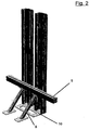
- Fig. 1 one recognizes the horizontal section through a support for the wearer of a belt restraint system.
- This support has a wall 1, which revolves around a central space 2.
- the ends of the wall 1 are laterally a vertically extending opening slot 3, via which the central space 2 lying in the interior of the support is connected to the environment.
- the cross section through the support thus basically has the shape of a ⁇ .
- a cross member 5 and - if necessary, also on the cross member 5 - oblique supports 6 are attached.
- the flange 4 may be provided with T-grooves 7.
- the in Fig. 1 illustrated embodiment on the one hand also another T-slot 11 on its rear side 12 and T-slots 13 at the respective opposite lateral areas.
- the substantially C-shaped T-slots have at least partially greater thicknesses of their wall portions 15, which also higher clamping forces can be applied here if necessary, if attached via these T-slots here not shown elements on the support become.
- FIG. 3 is a sectional view through a further embodiment of a support to recognize. In this identical parts are provided with identical reference numerals.
- the further embodiment shown here is characterized in particular by the fact that it has arranged in the central space 2 nor a center wall 16 which is connected to the rear side 12 of the support.
- This rear side 12 of the support is retracted in the region of its connection to the center wall 16 via two bevelled wall sections 17.
- In the corner 18 formed by the two wall sections 17 and the middle wall 16 is another Einschraubkanal 19, which - as well as the previously discussed Einschraubkanal 9 - is open to the outside and can otherwise serve a normal to the drawing plane running a fastening screw to provide another connection point with a bottom plate.
- the middle wall 16 carries at its front, in the region of the opening slot 3 end also a T-slot portion 20, wherein the front side 21 of this T-groove is flush with the flange 4, which at the respective outer edges of the opening slot 3 at this adjoin.
- the supports shown here are made as extruded aluminum profiles with wall, flanges, T-slots, etc. in one piece.
Abstract
Die Erfindung betrifft einen Träger für ein Gurtrückhaltesystem für ein Fahrzeug, insbesondere ein Wohnmobil oder einen Transporter, mit wenigstens einer vertikal verlaufenden Stütze. Um diesen Träger in seiner Verwendbarkeit und seiner Anschließbarkeit an die Strukturen des Fahrzeuges zu verbessern, wird vorgeschlagen, dass die Stütze in Horizontalrichtung einen sich nach vorne verjüngenden, im Wesentlichen ringförmigen und mit einem vertikalen Öffnungsschlitz (3) versehen, offenen ©förmigen Querschnitt mit einer um einen Mittelraum (2) umlaufenden Wandung (1) aufweist, mit seitlich des Öffnungsschlitzes (3) liegenden, sich in Querrichtung erstreckenden Flanschflächen (4). Weiterhin kann eine solche Stütze mit T-Nuten versehen werden. Eine solche Stütze kann insbesondere als Aluminiumstrangpressprofil realisiert werden.The invention relates to a carrier for a belt restraint system for a vehicle, in particular a motorhome or a van, with at least one vertically extending support. In order to improve this carrier in its usability and its connectability to the structures of the vehicle, it is proposed that the support in the horizontal direction a forwardly tapering, substantially annular and with a vertical opening slot (3) provided, open © shaped cross-section with a around a central space (2) encircling wall (1), with laterally of the opening slit (3) lying in the transverse direction extending flange surfaces (4). Furthermore, such a support can be provided with T-slots. Such a support can be realized in particular as an aluminum extruded profile.
Description
Die Erfindung betrifft einen Träger für ein Gurtrückhaltesystem für ein Fahrzeug, insbesondere ein Wohnmobil oder einen Transporter, mit wenigstens einer im Wesentlichen vertikal verlaufenden Stütze.The invention relates to a carrier for a belt restraint system for a vehicle, in particular a motorhome or a van, with at least one substantially vertically extending support.
Wohnmobile werden üblicherweise auf Fahrgestellen von Kleintransportern aufgebaut. Es wird dabei im Wesentlichen unterschieden, ob man Kastenwagen, teilintegrierte Wohnmobile oder aber vollintegrierte Wohnmobile hat. Bei Kastenwagen und teilintegrierten Wohnmobilen wird ein vorhandenes Fahrzeug eines Transporterherstellers als Wohnmobilbasis benutzt und durch einen Ausbau bzw. Aufbau im Wohnbereich ergänzt.Motorhomes are usually built on chassis of vans. It is essentially distinguished, whether you have van, semi-integrated campers or fully integrated campers. In panel vans and semi-integrated motorhomes, an existing vehicle of a van manufacturer is used as a motorhome base and supplemented by an expansion or construction in the living area.
Bei den vollintegrierten Wohnmobilen ist der Fahrerbereich vollständig in das Fahrzeug und damit in den Wohnbereich integriert. Man verzichtet also auf die Verwendung eines vom Lieferanten des Transporters stammendes Führerhaus und baut dieses stattdessen mit Fenstern, Türen und Wandung zusammen mit dem Wohnbereich auf.In the fully integrated motorhomes, the driver area is completely integrated into the vehicle and thus into the living area. It dispenses with the use of a coming from the supplier of the van cab and builds this instead with windows, doors and walls together with the living area.
Problematisch dabei ist die Anbringung von für Passagiere vorgesehenen und deshalb vorgeschriebenen Gurtrückhaltesystemen, für die eine feste Verankerung vorzusehen ist.The problem here is the attachment of provided for passengers and therefore prescribed Gurte restraint systems, for which a firm anchorage is provided.
Bei den Kastenwagen und teilintegrierten Wohnmobilen können diese, soweit sie für im Führerhaus sitzende Passagiere vorgesehen sind, an den serienmäßig vom Transporterhersteller z.B. an der sogenannten B-Säule angebrachten Befestigungspunkten angebracht werden.In the panel van and semi-integrated motorhomes, these can, as far as they are provided for sitting in the cab passengers are attached to the standard by the van manufacturer, for example, attached to the so-called B-pillar attachment points.
Bei den vollintegrierten Wohnmobilen werden die vorgeschriebenen Gurtrückhaltesysteme statt dessen oft auch integriert an den Passagiersitzen im Fahrerhaus befestigt, die in die Wohnmobile eingebaut werden, um die beim Auftreten eines Unfalles am Gurtrückhaltesystem wirkenden Kräfte aufzunehmen und in die Fahrzeugstruktur ableiten zu können.In the fully integrated motorhomes the prescribed belt restraint systems are often also integrated integrated into the passenger seats in the cab, which are installed in the motorhomes to absorb the forces acting on the belt restraint system in the event of an accident and to divert forces into the vehicle structure.
Dies ist insbesondere deshalb notwendig, weil die für die Wände von derartigen Wohnmobilaufbauten üblicherweise verwendeten Plattenmaterialien, die insbesondere unter den Gesichtspunkten von geringem Gewicht und hoher thermischer Isolation ausgewählt werden, für die Aufnahme von derartigen Kräften nicht geeignet sind, die Gurtrückhaltesysteme also nur schwierig an den Wänden befestigt werden können.This is necessary in particular because the plate materials commonly used for the walls of such motorhome structures, which are chosen in particular from the viewpoint of low weight and high thermal insulation, are not suitable for absorbing such forces, the Gurtrückhaltesysteme so difficult to the Walls can be attached.
Das vergleichbare Problem stellt sich somit auch für die Befestigung von Gurtrückhaltesystemen, die für Passagiere vorgesehen und vorgeschrieben sind, die im eigentlichen Wohnbereich eines Wohnmobils mitreisen, wenn dieses für mehr als zwei Personen zugelassen ist, also auch außerhalb des Fahrerhauses mit normalerweise zwei Plätzen weitere Passagiersitze vorgesehen sein müssen.The similar problem thus arises also for the attachment of Gurte restraint systems, which are provided and prescribed for passengers who travel in the actual living area of a motorhome, if this is allowed for more than two people, including outside the cab with normally two seats more passenger seats must be provided.
Diese Passagiere reisen dabei häufig auf einer Sitzbank mit, die in das Wohnmobil als Teil einer Sitz- oder Tischkombination integriert ist, die auch als Dinette bezeichnet wird und im stationären Zustand des Wohnmobils häufig auch zu einem Schlafplatz umzubauen ist.These passengers often travel on a bench, which is integrated into the motorhome as part of a seat or table combination, which is also referred to as dinette and in the stationary state of the motorhome is often convert to a sleeping space.
Die für Passagiere, die auf derartigen Sitzbänken reisen, vorgesehenen Gurtrückhaltesysteme sind ebenfalls nicht an den Materialien zu befestigen, aus denen die Sitzbank gefertigt ist oder die benachbart zu diesen Sitzbänken angeordnet sind und aus denen insbesondere auch die Möbeleinbauten des Wohnmobils hergestellt sind, da diese Materialien z.B. als Möbelbau-Spanplatten für die Aufnahme von an einem Gurtrückhaltesystem auftretenden Kräfte nicht entsprechend dimensioniert sind.The provided for passengers who travel on such benches, Gurte restraint systems are also not to attach to the materials from which the seat is made or which are arranged adjacent to these benches and from which in particular the furniture of the camper are made, as these materials eg are not dimensioned as furniture chipboards for receiving forces occurring on a belt restraint system.
Stattdessen werden die Gurtrückhaltesysteme an Trägern befestigt, die separat in die Wohnmobile eingebaut werden.Instead, the belt restraint systems are attached to straps that are installed separately in the RVs.
Häufig werden für derartige Träger dabei Konstruktionen aus Eisen- oder Stahlprofilen verwendet, da diese insbesondere gut schweißbar sind.Constructions of iron or steel profiles are often used for such carrier, since these are particularly good weldability.
Nachteilig ist bei derartigen Konstruktionen aber, dass sie insbesondere sehr schwer sind und dass sie üblicherweise jeweils spezifisch für einzelne Wohnmobilmodelle hergestellt werden, z.B. um unterschiedliche Höhen von Sitzbänken bei unterschiedlichen Wohnmobilaufbauten oder unterschiedliche Einbausituationen z.B. in Hinblick auf benachbart zu der Sitzbank befindlich Einbauten (Möbel/Wände/etc.) berücksichtigen zu können und vor allem um fahrzeugspezifisch eine zusätzliche Kraftableitung für die senkrechten Stützen vorzusehen, da hierfür notwendige Elemente im Wesentlichen an den Stützen angeschweißt werden müssen, um entsprechende Kräfte optimal aufnehmen und an im Bereich des Bodens des Wohnmobilaufbaus verlaufende Verstrebungen ableiten zu können.A disadvantage of such constructions, however, is that they are particularly very heavy and that they are usually each made specifically for individual RV models, e.g. different heights of benches for different RV or different installation situations, e.g. to be able to take into account internals (furniture / walls / etc.) in relation to the seat and, above all, to provide vehicle-specific additional power dissipation for the vertical supports, since necessary elements must essentially be welded to the supports in order to generate appropriate forces optimally absorb and to be able to derive in the area of the floor of the motorhome structure extending struts.
Aufgabe der vorliegenden Erfindung ist es daher, einen Träger für ein Gurtrückhaltesystem wie oben beschrieben dahingehend weiter zu entwickeln, dass sowohl die Anbringung von beispielsweise Gurtumlenkpunkten an verschiedensten Stellen möglich ist und auch die Verbindung von bei diesen Trägern vorhandenen Stützen mit beispielsweise Querträgern oder ähnlichem zu erleichtern ist.The object of the present invention is therefore to further develop a carrier for a belt restraint system as described above, in that attachment of, for example, belt deflection points to various locations is possible and also to facilitate the connection of supports present in these carriers with, for example, cross members or the like is.
Diese Aufgabe wird erfindungsgemäß dadurch gelöst, dass die Stütze in Horizontalrichtung einen sich nach vorne verjüngenden, im Wesentlichen ringförmigen und mit einem vertikalen Öffnungsschlitz versehenen, offenen Ω-Querschnitt mit einer um einen Mittelraum umlaufenden Wandung aufweist mit seitlich des Öffnungsschlitzes liegenden, sich in Querrichtung erstreckenden Flanschflächen.This object is achieved in that the support in the horizontal direction has a forwardly tapered, substantially annular and provided with a vertical opening slot, open Ω-section with a circumferential wall around a central space with lying laterally of the opening slot, extending in the transverse direction flange surfaces.
Die Erfindung hat den Vorteil, dass eine derartige Stütze aufgrund des vertikal durchgängig verlaufenden Öffnungsschlitzes ermöglicht, in diesem beispielsweise einen Gurtumlenkpunkt stufenlos in jeder beliebigen Höhe zu befestigen. Gleichermaßen wird durch die sich in Querrichtung erstreckenden Flanschflächen, die sich seitlich an den Öffnungsschlitz anschließen, die Möglichkeit eröffnet, zusätzliche Abstützelemente oder aber Querträger etc. in optimierter Weise z.B. mittels Verklemmung oder auch einer Verklebung an die Stütze anzuschließen, wobei gleichzeitig durch die ringförmig um den Mittelraum umlaufende Wandung der Stütze eine ausreichende Steifigkeit und Torsionsfestigkeit der Stütze zu erreichen ist.The invention has the advantage that such a support allows due to the vertically continuous opening slot to fasten in this example, a Gurtumlenkpunkt stepless in any height. Likewise, by the transversely extending flange surfaces which laterally adjoin the aperture slot, opens up the possibility to connect additional support elements or cross member etc. in an optimized manner, for example by means of jamming or bonding to the support, while at the same time by the annular surrounding the central space wall of the support sufficient rigidity and torsional strength of the support can be achieved.
Um die Verwendungsmöglichkeit der Stütze zu verbessern, wird außerdem noch vorgeschlagen, die Flanschflächen mit T-Nuten zu besetzen. Damit besteht die Möglichkeit, weitere Elemente an der Stütze zu fixieren, die beispielsweise für den Innenausbau eines Wohnmobiles benötigt werden.In order to improve the possibility of using the support, it is also proposed to fill the flange surfaces with T-slots. This makes it possible to fix other elements on the support, which are needed for example for the interior of a motorhome.
Es ist dabei insbesondere vorgesehen, dass die Verbindung der Wandung, die bei der Stütze um den Mittelraum umläuft, mit den Flanschflächen, die sich seitlich vom Öffnungsschlitz anschließen, direkt benachbart zu diesem Öffnungsschlitz liegt. Damit sind im Bereich des Öffnungsschlitzes in den Träger eingeleitete Kräfte unmittelbar an die Wandung weiterzuführen.It is provided in particular that the connection of the wall, which rotates in the support to the central space, with the flange faces, which adjoin the side of the opening slot, directly adjacent to this opening slot. Thus, in the region of the opening slot, forces introduced into the carrier are to be continued directly to the wall.
Es wird dabei vorgeschlagen im Bereich der genannten Verbindung von Wandung und Flanschflächen die sich hier ergebende, insbesondere spitzwinkelige Ecke dazu zu nutzen, einen im Wesentlichen parallel zu dem Öffnungsschlitz verlaufenden Einschraubkanal vorzusehen. Mit diesem ist es insbesondere möglich, die Stütze an ihrem unteren Ende über eine Schraubverbindung mit einem sie tragenden Schuh zu verbinden.It is proposed in the area of said connection of wall and flange surfaces to use the here resulting, in particular acute-angled corner to provide a substantially parallel to the opening slot extending screw-in. With this it is particularly possible to connect the support at its lower end via a screw connection with a shoe carrying them.
Um die Verwendungsmöglichkeiten und dabei auch die Integrierbarkeit des Systems in den Aufbau eines Wohnmobils weiter zu verbessern, wird vorgeschlagen, dass die Stütze an ihrer Wandung seitlich und/oder an ihrer Rückseite mit wenigstens einer T-Nut versehen ist. Über diese können weitere Bauteile oder Bauelemente mit der Stütze verbunden werden.In order to further improve the possibilities of use and thereby also the integrability of the system in the construction of a mobile home, it is proposed that the support is provided on its wall laterally and / or on its rear side with at least one T-groove. About this more components or components can be connected to the support.
Die Wandstärke zumindest einzelner T-Nuten kann dabei größer sein als die der Wandung. Nicht nur, dass hierdurch die Stabilität der gesamten Stütze verbessert wird, es sind aufgrund derartig verstärkter Wände einer T-Nut in besonders effektiver Weise auch hohe Klemmkräfte aufbringbar, mit denen bedarfsweise Elemente an dieser T-Nut und damit an der Stütze zu befestigen sind.The wall thickness of at least individual T-slots can be greater than that of the wall. Not only does this improve the stability of the entire support, it is due to such reinforced walls of a T-slot in a particularly effective manner, high clamping forces can be applied with which, if necessary, elements to be attached to this T-slot and thus to the support.
Bei einer weiteren bevorzugten Ausführungsform der Erfindung ist in den von der Wandung der Stütze umgebenden Mittelraum wenigstens eine mit der Rückseite der Stütze verbundene Mittelwand vorhanden. Dies bewirkt eine verbesserte Biegesteifigkeit der Stütze, die im Falle eines Unfalles von Vorteil sein kann.In a further preferred embodiment of the invention, at least one center wall connected to the back of the support is present in the central space surrounding the wall of the support. This causes an improved flexural rigidity of the support, which can be advantageous in the event of an accident.
Es ist dabei im Rahmen der Erfindung, dass die Mittelwand im Bereich des Öffnungsschlitzes eine weitere T-Nut trägt. Dies verbessert die Einsetzbarkeit der Stütze weiter.It is within the scope of the invention that the middle wall in the region of the opening slot carries a further T-slot. This further improves the usability of the support.
Vorzugsweise ist dabei die Rückseite der Stütze im Bereich ihrer Verbindung mit der Mittelwand in den Mittelraum eingezogen. Auch hierdurch ist es möglich, die Stabilität der Stütze zu verbessern, insbesondere da so von der Mittelwand auf die Stütze wirkende Kräfte besser abgeleitet werden können.Preferably, the back of the support is retracted in the region of its connection with the middle wall in the central space. This also makes it possible to improve the stability of the support, especially as it can be better derived from the middle wall acting on the support forces.
Es wird vorzugsweise vorgeschlagen, die hier beschriebene Stütze als Strangpressprofil herzustellen, insbesondere aus Aluminium. Auf diese Weise sind derartige Elemente relativ kostengünstig herstellbar.It is preferably proposed to produce the support described here as an extruded profile, in particular of aluminum. In this way, such elements are relatively inexpensive to produce.
Weitere Vorteile und Merkmale der Erfindung ergeben sich aus der nachfolgenden Beschreibung von Ausführungsbeispielen. Dabei zeigt:
-
Fig. 1 einen Horizontalschnitt durch eine Stütze; -
Fig. 2 die perspektivische Ansicht einer Stütze gemäßFig. 1 ; -
Fig. 3 eine horizontale Schnittansicht einer Stütze mit Mittelwand;
-
Fig. 1 a horizontal section through a support; -
Fig. 2 the perspective view of a support according toFig. 1 ; -
Fig. 3 a horizontal sectional view of a support with a central wall;
In
Seitlich des Öffnungsschlitzes 3 sind sich in einer Querrichtung erstreckende, sich an die Wandung 1 anschließende und einstückig mit dieser verbundene Flanschflächen 4 zu erkennen. Der Querschnitt durch die Stütze hat somit grundsätzlich die Form eines Ω.Laterally of the
Wie in der
Es ist hier zu erkennen, dass die Wandung 1 an dem dem Öffnungsschlitz 3 zugewandten Bereich der Flansche 4 bzw. der T-Nuten 7 in diese übergehen. In der sich dabei bildenden insbesondere wie hier zu erkennen spitzwinkeligen Ecke 8 ist ein Einschraubkanal 9 angeordnet. Dieser Einschraubkanal 9 ist einerseits nach außen geöffnet, bietet andererseits aber auch die Möglichkeit, normal zur Zeichenebene entsprechende Befestigungsschrauben aufzunehmen, mit der die hier dargestellte Stütze beispielsweise an einer Bodenplatte 10 zu befestigen ist, wie dies in
Außer den T-Nuten 7 an der Vorderseite der Stütze weist die in
In der
Die hier dargestellte weitere Ausführungsform zeichnet sich insbesondere dadurch aus, dass sie in den Mittelraum 2 noch eine Mittelwand 16 angeordnet hat, die an der Rückseite 12 der Stütze angeschlossen ist. Diese Rückseite 12 der Stütze ist dabei im Bereich ihrer Verbindung mit der Mittelwand 16 über zwei abgeschrägte Wandabschnitte 17 eingezogen. In der durch die beiden Wandabschnitte 17 sowie die Mittelwand 16 gebildeten Ecke 18 befindet sich ein weiterer Einschraubkanal 19, der - wie auch der schon oben diskutierte Einschraubkanal 9 - nach außen offen ist und ansonsten dazu dienen kann, über eine normal zur Zeichenebene laufende Befestigungsschraube einen weiteren Verbindungspunkt mit einer Bodenplatte zu liefern.The further embodiment shown here is characterized in particular by the fact that it has arranged in the
Die Mittelwand 16 trägt an ihrem vorderen, im Bereich des Öffnungsschlitzes 3 liegenden Endes auch noch einen T-Nut-Abschnitt 20, wobei die Vorderseite 21 dieser T-Nut mit den Flanschflächen 4 fluchtet, die an den jeweils außenliegenden Kanten des Öffnungsschlitzes 3 an diesen angrenzen.The
Die hier dargestellten Stützen sind als Strangpressprofile aus Aluminium mit Wandung, Flanschen, T-Nuten etc. einstückig hergestellt.The supports shown here are made as extruded aluminum profiles with wall, flanges, T-slots, etc. in one piece.
- 11
- Wandungwall
- 22
- Mittelraummedia room
- 33
- Öffnungsschlitzopening slot
- 44
- Flanschflächenflange
- 55
- Querträgercrossbeam
- 66
- Schrägstützendiagonal supports
- 77
- T-NutenT-grooves
- 88th
- Eckecorner
- 99
- Einschraubkanalscrewing passage
- 1010
- Bodenplattebaseplate
- 1111
- T-NutT-slot
- 1212
- Rückseiteback
- 1313
- T-NutenT-grooves
- 1414
- seitlicher Bereichlateral area
- 1515
- Wandbereichewall areas
- 1616
- Mittelwandcenter wall
- 1717
- abgeschrägte Wandabschnittebevelled wall sections
- 1818
- Eckecorner
- 1919
- Einschraubkanalscrewing passage
- 2020
- T-Nut-AbschnittT-slot section
- 2121
- Vorderseitefront
Claims (10)
dadurch gekennzeichnet,
dass die Stütze in Horizontalrichtung einen sich nach vorne verjüngenden, im Wesentlichen ringförmigen und mit einem vertikalen Öffnungsschlitz (3) versehen, offenen Ω-förmigen Querschnitt mit einer um einen Mittelraum (2) umlaufenden Wandung (1) aufweist, mit seitlich des Öffnungsschlitzes (3) liegenden, sich in Querrichtung erstreckenden Flanschflächen (4).Support for a belt restraint system for a vehicle, in particular a mobile home or a van, with at least one vertical support,
characterized,
in that the support has in the horizontal direction a forwardly tapered, substantially annular and with a vertical opening slot (3), open Ω-shaped cross-section with a wall (1) encircling a central space (2) with laterally of the opening slot (3 ) lying transversely extending flange surfaces (4).
dadurch gekennzeichnet,
dass die Flanschflächen (4) mit T-Nuten (7) besetzt sind.Carrier according to claim 1,
characterized,
that the flange (4) are held by T-grooves (7).
dadurch gekennzeichnet,
dass die Verbindung der Wandung (1) mit den Flanschflächen (4) im Bereich des Öffnungsschlitzes (3) ist.Support according to claim 1 or 2,
characterized,
that the connection of the wall (1) with the flange surfaces (4) in the region of the opening slot (3).
dadurch gekennzeichnet,
dass im Bereich der Verbindung ein im Wesentlichen parallel zum Öffnungsschlitz (3) verlaufender Einschraubkanal (9) ist.Carrier according to claim 3,
characterized,
in that in the region of the connection there is a screw-in channel (9) extending essentially parallel to the opening slot (3).
dadurch gekennzeichnet,
dass die Stütze an ihrer Wandung (1) seitlich und/oder an ihrer Rückseite (12) mit wenigstens einer T-Nut (13; 11) versehen ist.Support according to one or more of the preceding claims,
characterized,
that the support on its wall (1) is laterally and / or on its rear side (12) with at least one T-groove (13; 11) is provided.
dadurch gekennzeichnet,
dass in dem Mittelraum (2) mindestens eine mit der Rückseite (12) der Stütze verbundene Mittelwand (16) ist.Support according to one or more of the preceding claims,
characterized,
in that at least one center wall (16) connected to the back (12) of the support is in the central space (2).
dadurch gekennzeichnet,
dass die Mittelwand (16) im Bereich des Öffnungsschlitzes (3) einen T-Nut-Abschnitt (20) trägt.Support according to claim 6,
characterized,
that the middle wall (16) in the region of the opening slot (3) carries a T-groove portion (20).
dadurch gekennzeichnet,
dass die Rückseite (12) im Bereich der Verbindung mit der Mittelwand (16) in den Mittelraum (2) eingezogen ist.Support according to one or more of the preceding claims,
characterized,
that the rear side (12) is retracted in the region of the connection with the central wall (16) in the middle chamber (2).
dadurch gekennzeichnet,
dass die T-Nut (7, 11, 13) gegenüber der Wandung (1) eine größere Wanddicke aufweist.Support according to one or more of the preceding claims,
characterized,
that the T-groove (7, 11, 13) opposite the wall (1) has a greater wall thickness.
dadurch gekennzeichnet,
dass die Stütze als Aluminiumstrangpressprofil ausgebildet ist.Support according to one or more of the preceding claims,
characterized,
that the support is designed as an aluminum extruded profile.
Applications Claiming Priority (1)
| Application Number | Priority Date | Filing Date | Title |
|---|---|---|---|
| DE102016004614.7A DE102016004614A1 (en) | 2016-04-19 | 2016-04-19 | Carrier for a belt restraint system |
Publications (2)
| Publication Number | Publication Date |
|---|---|
| EP3235693A1 true EP3235693A1 (en) | 2017-10-25 |
| EP3235693B1 EP3235693B1 (en) | 2018-11-07 |
Family
ID=58428030
Family Applications (1)
| Application Number | Title | Priority Date | Filing Date |
|---|---|---|---|
| EP17000474.1A Active EP3235693B1 (en) | 2016-04-19 | 2017-03-22 | Support for a belt retention system |
Country Status (2)
| Country | Link |
|---|---|
| EP (1) | EP3235693B1 (en) |
| DE (1) | DE102016004614A1 (en) |
Cited By (1)
| Publication number | Priority date | Publication date | Assignee | Title |
|---|---|---|---|---|
| EP4269185A1 (en) * | 2022-04-30 | 2023-11-01 | Hymer GmbH & Co. KG | Recreational vehicle, in particular camper, and bracket assembly for belt |
Families Citing this family (1)
| Publication number | Priority date | Publication date | Assignee | Title |
|---|---|---|---|---|
| DE102018006323A1 (en) | 2018-08-09 | 2019-02-14 | Daimler Ag | Seat belt system for a vehicle seat |
Citations (4)
| Publication number | Priority date | Publication date | Assignee | Title |
|---|---|---|---|---|
| DE9110381U1 (en) * | 1991-08-22 | 1991-10-10 | Niesmann-Bischoff Clou Gmbh, 5403 Muelheim-Kaerlich, De | |
| DE9413808U1 (en) * | 1993-09-01 | 1994-10-13 | Kohlhauser Gerhard | Multi-purpose profile |
| DE10103841A1 (en) * | 2001-01-25 | 2002-08-01 | Junker & Partner Gmbh | Profile with an undercut groove |
| DE102008008696A1 (en) * | 2008-02-11 | 2009-08-13 | Dorma Gmbh + Co. Kg | Profile and profile system |
-
2016
- 2016-04-19 DE DE102016004614.7A patent/DE102016004614A1/en not_active Withdrawn
-
2017
- 2017-03-22 EP EP17000474.1A patent/EP3235693B1/en active Active
Patent Citations (4)
| Publication number | Priority date | Publication date | Assignee | Title |
|---|---|---|---|---|
| DE9110381U1 (en) * | 1991-08-22 | 1991-10-10 | Niesmann-Bischoff Clou Gmbh, 5403 Muelheim-Kaerlich, De | |
| DE9413808U1 (en) * | 1993-09-01 | 1994-10-13 | Kohlhauser Gerhard | Multi-purpose profile |
| DE10103841A1 (en) * | 2001-01-25 | 2002-08-01 | Junker & Partner Gmbh | Profile with an undercut groove |
| DE102008008696A1 (en) * | 2008-02-11 | 2009-08-13 | Dorma Gmbh + Co. Kg | Profile and profile system |
Cited By (1)
| Publication number | Priority date | Publication date | Assignee | Title |
|---|---|---|---|---|
| EP4269185A1 (en) * | 2022-04-30 | 2023-11-01 | Hymer GmbH & Co. KG | Recreational vehicle, in particular camper, and bracket assembly for belt |
Also Published As
| Publication number | Publication date |
|---|---|
| DE102016004614A1 (en) | 2017-10-19 |
| EP3235693B1 (en) | 2018-11-07 |
Similar Documents
| Publication | Publication Date | Title |
|---|---|---|
| EP2570322B1 (en) | Holder element for constructing a floor of a rail vehicle car, floor of a rail vehicle car and rail vehicle car | |
| DE102007036670B4 (en) | Kit for building a floor for a rail vehicle | |
| DE102007032235B4 (en) | Light rail system for transferring heavy loads into a structure | |
| EP3235693B1 (en) | Support for a belt retention system | |
| DE102012213469C5 (en) | Roof wall arrangement, in particular for a road-bound vehicle | |
| DE102010011568A1 (en) | Coach body for rail vehicle, comprises roof structure and base structure, where roof structure or base structure comprises frame, which is fastened at walls of coach body | |
| DE102012110938B4 (en) | Side element device for a bus, comprising a frame and a seat rail | |
| DE102017124370A1 (en) | VEHICLE DOOR VEHICLE ASSEMBLY | |
| DE102012213019B4 (en) | Zugkopfteil | |
| DE102014214913A1 (en) | Longitudinal support device for supporting a front engine in a motor vehicle | |
| EP2682303B1 (en) | Extruded profile and vehicle | |
| DE102013008299A1 (en) | Holding device, in particular for a vehicle seat | |
| DE4419139A1 (en) | Frame structure for vehicle seat | |
| EP3752388B1 (en) | Attachment for internal fixtures of vehicles | |
| DE19927532C2 (en) | Mechanism for attaching a middle seat belt from a vehicle seat | |
| DE202016102135U1 (en) | Gurtbockanordnung | |
| EP0201803A2 (en) | Camping vehicle | |
| DE19949372C2 (en) | Frame construction and connecting element therefor | |
| DE102006023169B4 (en) | Component for a commercial vehicle body, commercial vehicle with such a component and method for producing such a component | |
| EP2895371B1 (en) | Passenger rail vehicle | |
| EP2945827B1 (en) | Assembly device for a side wall cladding element of a rail vehicle | |
| DE3541325A1 (en) | Connecting element | |
| DE202015104619U1 (en) | Supplementary support flange for a vehicle frame column and extended glazed opening of a panoramic sun roof | |
| DE102021124293A1 (en) | Recreational vehicle and trailer hitch assembly for a recreational vehicle | |
| EP2956346B1 (en) | Construction kit for producing a rail vehicle with flexible door and window divider |
Legal Events
| Date | Code | Title | Description |
|---|---|---|---|
| PUAI | Public reference made under article 153(3) epc to a published international application that has entered the european phase |
Free format text: ORIGINAL CODE: 0009012 |
|
| STAA | Information on the status of an ep patent application or granted ep patent |
Free format text: STATUS: THE APPLICATION HAS BEEN PUBLISHED |
|
| AK | Designated contracting states |
Kind code of ref document: A1 Designated state(s): AL AT BE BG CH CY CZ DE DK EE ES FI FR GB GR HR HU IE IS IT LI LT LU LV MC MK MT NL NO PL PT RO RS SE SI SK SM TR |
|
| AX | Request for extension of the european patent |
Extension state: BA ME |
|
| STAA | Information on the status of an ep patent application or granted ep patent |
Free format text: STATUS: REQUEST FOR EXAMINATION WAS MADE |
|
| 17P | Request for examination filed |
Effective date: 20171221 |
|
| RBV | Designated contracting states (corrected) |
Designated state(s): AL AT BE BG CH CY CZ DE DK EE ES FI FR GB GR HR HU IE IS IT LI LT LU LV MC MK MT NL NO PL PT RO RS SE SI SK SM TR |
|
| GRAP | Despatch of communication of intention to grant a patent |
Free format text: ORIGINAL CODE: EPIDOSNIGR1 |
|
| STAA | Information on the status of an ep patent application or granted ep patent |
Free format text: STATUS: GRANT OF PATENT IS INTENDED |
|
| INTG | Intention to grant announced |
Effective date: 20180705 |
|
| GRAS | Grant fee paid |
Free format text: ORIGINAL CODE: EPIDOSNIGR3 |
|
| GRAA | (expected) grant |
Free format text: ORIGINAL CODE: 0009210 |
|
| STAA | Information on the status of an ep patent application or granted ep patent |
Free format text: STATUS: THE PATENT HAS BEEN GRANTED |
|
| AK | Designated contracting states |
Kind code of ref document: B1 Designated state(s): AL AT BE BG CH CY CZ DE DK EE ES FI FR GB GR HR HU IE IS IT LI LT LU LV MC MK MT NL NO PL PT RO RS SE SI SK SM TR |
|
| REG | Reference to a national code |
Ref country code: GB Ref legal event code: FG4D Free format text: NOT ENGLISH |
|
| REG | Reference to a national code |
Ref country code: CH Ref legal event code: EP Ref country code: AT Ref legal event code: REF Ref document number: 1061683 Country of ref document: AT Kind code of ref document: T Effective date: 20181115 |
|
| REG | Reference to a national code |
Ref country code: DE Ref legal event code: R096 Ref document number: 502017000310 Country of ref document: DE |
|
| REG | Reference to a national code |
Ref country code: IE Ref legal event code: FG4D Free format text: LANGUAGE OF EP DOCUMENT: GERMAN |
|
| REG | Reference to a national code |
Ref country code: NL Ref legal event code: MP Effective date: 20181107 |
|
| REG | Reference to a national code |
Ref country code: LT Ref legal event code: MG4D |
|
| PG25 | Lapsed in a contracting state [announced via postgrant information from national office to epo] |
Ref country code: ES Free format text: LAPSE BECAUSE OF FAILURE TO SUBMIT A TRANSLATION OF THE DESCRIPTION OR TO PAY THE FEE WITHIN THE PRESCRIBED TIME-LIMIT Effective date: 20181107 Ref country code: IS Free format text: LAPSE BECAUSE OF FAILURE TO SUBMIT A TRANSLATION OF THE DESCRIPTION OR TO PAY THE FEE WITHIN THE PRESCRIBED TIME-LIMIT Effective date: 20190307 Ref country code: NO Free format text: LAPSE BECAUSE OF FAILURE TO SUBMIT A TRANSLATION OF THE DESCRIPTION OR TO PAY THE FEE WITHIN THE PRESCRIBED TIME-LIMIT Effective date: 20190207 Ref country code: LT Free format text: LAPSE BECAUSE OF FAILURE TO SUBMIT A TRANSLATION OF THE DESCRIPTION OR TO PAY THE FEE WITHIN THE PRESCRIBED TIME-LIMIT Effective date: 20181107 Ref country code: BG Free format text: LAPSE BECAUSE OF FAILURE TO SUBMIT A TRANSLATION OF THE DESCRIPTION OR TO PAY THE FEE WITHIN THE PRESCRIBED TIME-LIMIT Effective date: 20190207 Ref country code: HR Free format text: LAPSE BECAUSE OF FAILURE TO SUBMIT A TRANSLATION OF THE DESCRIPTION OR TO PAY THE FEE WITHIN THE PRESCRIBED TIME-LIMIT Effective date: 20181107 Ref country code: FI Free format text: LAPSE BECAUSE OF FAILURE TO SUBMIT A TRANSLATION OF THE DESCRIPTION OR TO PAY THE FEE WITHIN THE PRESCRIBED TIME-LIMIT Effective date: 20181107 Ref country code: LV Free format text: LAPSE BECAUSE OF FAILURE TO SUBMIT A TRANSLATION OF THE DESCRIPTION OR TO PAY THE FEE WITHIN THE PRESCRIBED TIME-LIMIT Effective date: 20181107 |
|
| PG25 | Lapsed in a contracting state [announced via postgrant information from national office to epo] |
Ref country code: SE Free format text: LAPSE BECAUSE OF FAILURE TO SUBMIT A TRANSLATION OF THE DESCRIPTION OR TO PAY THE FEE WITHIN THE PRESCRIBED TIME-LIMIT Effective date: 20181107 Ref country code: NL Free format text: LAPSE BECAUSE OF FAILURE TO SUBMIT A TRANSLATION OF THE DESCRIPTION OR TO PAY THE FEE WITHIN THE PRESCRIBED TIME-LIMIT Effective date: 20181107 Ref country code: RS Free format text: LAPSE BECAUSE OF FAILURE TO SUBMIT A TRANSLATION OF THE DESCRIPTION OR TO PAY THE FEE WITHIN THE PRESCRIBED TIME-LIMIT Effective date: 20181107 Ref country code: AL Free format text: LAPSE BECAUSE OF FAILURE TO SUBMIT A TRANSLATION OF THE DESCRIPTION OR TO PAY THE FEE WITHIN THE PRESCRIBED TIME-LIMIT Effective date: 20181107 Ref country code: GR Free format text: LAPSE BECAUSE OF FAILURE TO SUBMIT A TRANSLATION OF THE DESCRIPTION OR TO PAY THE FEE WITHIN THE PRESCRIBED TIME-LIMIT Effective date: 20190208 Ref country code: PT Free format text: LAPSE BECAUSE OF FAILURE TO SUBMIT A TRANSLATION OF THE DESCRIPTION OR TO PAY THE FEE WITHIN THE PRESCRIBED TIME-LIMIT Effective date: 20190307 |
|
| PG25 | Lapsed in a contracting state [announced via postgrant information from national office to epo] |
Ref country code: PL Free format text: LAPSE BECAUSE OF FAILURE TO SUBMIT A TRANSLATION OF THE DESCRIPTION OR TO PAY THE FEE WITHIN THE PRESCRIBED TIME-LIMIT Effective date: 20181107 Ref country code: DK Free format text: LAPSE BECAUSE OF FAILURE TO SUBMIT A TRANSLATION OF THE DESCRIPTION OR TO PAY THE FEE WITHIN THE PRESCRIBED TIME-LIMIT Effective date: 20181107 Ref country code: IT Free format text: LAPSE BECAUSE OF FAILURE TO SUBMIT A TRANSLATION OF THE DESCRIPTION OR TO PAY THE FEE WITHIN THE PRESCRIBED TIME-LIMIT Effective date: 20181107 Ref country code: CZ Free format text: LAPSE BECAUSE OF FAILURE TO SUBMIT A TRANSLATION OF THE DESCRIPTION OR TO PAY THE FEE WITHIN THE PRESCRIBED TIME-LIMIT Effective date: 20181107 |
|
| REG | Reference to a national code |
Ref country code: DE Ref legal event code: R097 Ref document number: 502017000310 Country of ref document: DE |
|
| PG25 | Lapsed in a contracting state [announced via postgrant information from national office to epo] |
Ref country code: EE Free format text: LAPSE BECAUSE OF FAILURE TO SUBMIT A TRANSLATION OF THE DESCRIPTION OR TO PAY THE FEE WITHIN THE PRESCRIBED TIME-LIMIT Effective date: 20181107 Ref country code: SM Free format text: LAPSE BECAUSE OF FAILURE TO SUBMIT A TRANSLATION OF THE DESCRIPTION OR TO PAY THE FEE WITHIN THE PRESCRIBED TIME-LIMIT Effective date: 20181107 Ref country code: RO Free format text: LAPSE BECAUSE OF FAILURE TO SUBMIT A TRANSLATION OF THE DESCRIPTION OR TO PAY THE FEE WITHIN THE PRESCRIBED TIME-LIMIT Effective date: 20181107 Ref country code: SK Free format text: LAPSE BECAUSE OF FAILURE TO SUBMIT A TRANSLATION OF THE DESCRIPTION OR TO PAY THE FEE WITHIN THE PRESCRIBED TIME-LIMIT Effective date: 20181107 |
|
| PLBE | No opposition filed within time limit |
Free format text: ORIGINAL CODE: 0009261 |
|
| STAA | Information on the status of an ep patent application or granted ep patent |
Free format text: STATUS: NO OPPOSITION FILED WITHIN TIME LIMIT |
|
| 26N | No opposition filed |
Effective date: 20190808 |
|
| PG25 | Lapsed in a contracting state [announced via postgrant information from national office to epo] |
Ref country code: MC Free format text: LAPSE BECAUSE OF FAILURE TO SUBMIT A TRANSLATION OF THE DESCRIPTION OR TO PAY THE FEE WITHIN THE PRESCRIBED TIME-LIMIT Effective date: 20181107 Ref country code: SI Free format text: LAPSE BECAUSE OF FAILURE TO SUBMIT A TRANSLATION OF THE DESCRIPTION OR TO PAY THE FEE WITHIN THE PRESCRIBED TIME-LIMIT Effective date: 20181107 |
|
| PG25 | Lapsed in a contracting state [announced via postgrant information from national office to epo] |
Ref country code: LU Free format text: LAPSE BECAUSE OF NON-PAYMENT OF DUE FEES Effective date: 20190322 |
|
| REG | Reference to a national code |
Ref country code: BE Ref legal event code: MM Effective date: 20190331 |
|
| PG25 | Lapsed in a contracting state [announced via postgrant information from national office to epo] |
Ref country code: IE Free format text: LAPSE BECAUSE OF NON-PAYMENT OF DUE FEES Effective date: 20190322 |
|
| PG25 | Lapsed in a contracting state [announced via postgrant information from national office to epo] |
Ref country code: BE Free format text: LAPSE BECAUSE OF NON-PAYMENT OF DUE FEES Effective date: 20190331 |
|
| PG25 | Lapsed in a contracting state [announced via postgrant information from national office to epo] |
Ref country code: TR Free format text: LAPSE BECAUSE OF FAILURE TO SUBMIT A TRANSLATION OF THE DESCRIPTION OR TO PAY THE FEE WITHIN THE PRESCRIBED TIME-LIMIT Effective date: 20181107 |
|
| PG25 | Lapsed in a contracting state [announced via postgrant information from national office to epo] |
Ref country code: MT Free format text: LAPSE BECAUSE OF FAILURE TO SUBMIT A TRANSLATION OF THE DESCRIPTION OR TO PAY THE FEE WITHIN THE PRESCRIBED TIME-LIMIT Effective date: 20181107 |
|
| REG | Reference to a national code |
Ref country code: CH Ref legal event code: PL |
|
| PG25 | Lapsed in a contracting state [announced via postgrant information from national office to epo] |
Ref country code: LI Free format text: LAPSE BECAUSE OF NON-PAYMENT OF DUE FEES Effective date: 20200331 Ref country code: CH Free format text: LAPSE BECAUSE OF NON-PAYMENT OF DUE FEES Effective date: 20200331 |
|
| PG25 | Lapsed in a contracting state [announced via postgrant information from national office to epo] |
Ref country code: CY Free format text: LAPSE BECAUSE OF FAILURE TO SUBMIT A TRANSLATION OF THE DESCRIPTION OR TO PAY THE FEE WITHIN THE PRESCRIBED TIME-LIMIT Effective date: 20181107 |
|
| PG25 | Lapsed in a contracting state [announced via postgrant information from national office to epo] |
Ref country code: HU Free format text: LAPSE BECAUSE OF FAILURE TO SUBMIT A TRANSLATION OF THE DESCRIPTION OR TO PAY THE FEE WITHIN THE PRESCRIBED TIME-LIMIT; INVALID AB INITIO Effective date: 20170322 |
|
| GBPC | Gb: european patent ceased through non-payment of renewal fee |
Effective date: 20210322 |
|
| PG25 | Lapsed in a contracting state [announced via postgrant information from national office to epo] |
Ref country code: GB Free format text: LAPSE BECAUSE OF NON-PAYMENT OF DUE FEES Effective date: 20210322 |
|
| PG25 | Lapsed in a contracting state [announced via postgrant information from national office to epo] |
Ref country code: MK Free format text: LAPSE BECAUSE OF FAILURE TO SUBMIT A TRANSLATION OF THE DESCRIPTION OR TO PAY THE FEE WITHIN THE PRESCRIBED TIME-LIMIT Effective date: 20181107 |
|
| PGFP | Annual fee paid to national office [announced via postgrant information from national office to epo] |
Ref country code: FR Payment date: 20230320 Year of fee payment: 7 Ref country code: AT Payment date: 20230317 Year of fee payment: 7 |
|
| PGFP | Annual fee paid to national office [announced via postgrant information from national office to epo] |
Ref country code: DE Payment date: 20230320 Year of fee payment: 7 |
|
| P01 | Opt-out of the competence of the unified patent court (upc) registered |
Effective date: 20231117 |
|
| PGFP | Annual fee paid to national office [announced via postgrant information from national office to epo] |
Ref country code: AT Payment date: 20240318 Year of fee payment: 8 |