EP3234708B1 - Convertible intelligent power tool - Google Patents
Convertible intelligent power tool Download PDFInfo
- Publication number
- EP3234708B1 EP3234708B1 EP15820392.7A EP15820392A EP3234708B1 EP 3234708 B1 EP3234708 B1 EP 3234708B1 EP 15820392 A EP15820392 A EP 15820392A EP 3234708 B1 EP3234708 B1 EP 3234708B1
- Authority
- EP
- European Patent Office
- Prior art keywords
- servo
- module
- base unit
- tool
- configuration
- Prior art date
- Legal status (The legal status is an assumption and is not a legal conclusion. Google has not performed a legal analysis and makes no representation as to the accuracy of the status listed.)
- Active
Links
- 238000000034 method Methods 0.000 claims description 27
- 238000004891 communication Methods 0.000 claims description 16
- 238000012545 processing Methods 0.000 claims description 10
- 238000012544 monitoring process Methods 0.000 claims description 3
- 238000006243 chemical reaction Methods 0.000 claims description 2
- 238000011144 upstream manufacturing Methods 0.000 description 8
- 238000005259 measurement Methods 0.000 description 5
- 238000013461 design Methods 0.000 description 3
- 230000006870 function Effects 0.000 description 3
- 239000004973 liquid crystal related substance Substances 0.000 description 2
- 238000004519 manufacturing process Methods 0.000 description 2
- 230000001681 protective effect Effects 0.000 description 2
- 238000012546 transfer Methods 0.000 description 2
- 230000005540 biological transmission Effects 0.000 description 1
- 238000010586 diagram Methods 0.000 description 1
- 230000003993 interaction Effects 0.000 description 1
Images


Classifications
-
- B—PERFORMING OPERATIONS; TRANSPORTING
- B25—HAND TOOLS; PORTABLE POWER-DRIVEN TOOLS; MANIPULATORS
- B25F—COMBINATION OR MULTI-PURPOSE TOOLS NOT OTHERWISE PROVIDED FOR; DETAILS OR COMPONENTS OF PORTABLE POWER-DRIVEN TOOLS NOT PARTICULARLY RELATED TO THE OPERATIONS PERFORMED AND NOT OTHERWISE PROVIDED FOR
- B25F1/00—Combination or multi-purpose hand tools
- B25F1/02—Combination or multi-purpose hand tools with interchangeable or adjustable tool elements
- B25F1/04—Combination or multi-purpose hand tools with interchangeable or adjustable tool elements wherein the elements are brought into working positions by a pivoting or sliding movement
-
- G—PHYSICS
- G05—CONTROLLING; REGULATING
- G05B—CONTROL OR REGULATING SYSTEMS IN GENERAL; FUNCTIONAL ELEMENTS OF SUCH SYSTEMS; MONITORING OR TESTING ARRANGEMENTS FOR SUCH SYSTEMS OR ELEMENTS
- G05B19/00—Programme-control systems
- G05B19/02—Programme-control systems electric
- G05B19/18—Numerical control [NC], i.e. automatically operating machines, in particular machine tools, e.g. in a manufacturing environment, so as to execute positioning, movement or co-ordinated operations by means of programme data in numerical form
- G05B19/409—Numerical control [NC], i.e. automatically operating machines, in particular machine tools, e.g. in a manufacturing environment, so as to execute positioning, movement or co-ordinated operations by means of programme data in numerical form characterised by using manual input [MDI] or by using control panel, e.g. controlling functions with the panel; characterised by control panel details, by setting parameters
-
- B—PERFORMING OPERATIONS; TRANSPORTING
- B25—HAND TOOLS; PORTABLE POWER-DRIVEN TOOLS; MANIPULATORS
- B25B—TOOLS OR BENCH DEVICES NOT OTHERWISE PROVIDED FOR, FOR FASTENING, CONNECTING, DISENGAGING OR HOLDING
- B25B21/00—Portable power-driven screw or nut setting or loosening tools; Attachments for drilling apparatus serving the same purpose
- B25B21/002—Portable power-driven screw or nut setting or loosening tools; Attachments for drilling apparatus serving the same purpose for special purposes
-
- B—PERFORMING OPERATIONS; TRANSPORTING
- B25—HAND TOOLS; PORTABLE POWER-DRIVEN TOOLS; MANIPULATORS
- B25B—TOOLS OR BENCH DEVICES NOT OTHERWISE PROVIDED FOR, FOR FASTENING, CONNECTING, DISENGAGING OR HOLDING
- B25B23/00—Details of, or accessories for, spanners, wrenches, screwdrivers
- B25B23/14—Arrangement of torque limiters or torque indicators in wrenches or screwdrivers
- B25B23/15—Arrangement of torque limiters or torque indicators in wrenches or screwdrivers having a mechanism to mark the work when the selected torque is applied to the work
-
- B—PERFORMING OPERATIONS; TRANSPORTING
- B25—HAND TOOLS; PORTABLE POWER-DRIVEN TOOLS; MANIPULATORS
- B25F—COMBINATION OR MULTI-PURPOSE TOOLS NOT OTHERWISE PROVIDED FOR; DETAILS OR COMPONENTS OF PORTABLE POWER-DRIVEN TOOLS NOT PARTICULARLY RELATED TO THE OPERATIONS PERFORMED AND NOT OTHERWISE PROVIDED FOR
- B25F3/00—Associations of tools for different working operations with one portable power-drive means; Adapters therefor
-
- B—PERFORMING OPERATIONS; TRANSPORTING
- B25—HAND TOOLS; PORTABLE POWER-DRIVEN TOOLS; MANIPULATORS
- B25F—COMBINATION OR MULTI-PURPOSE TOOLS NOT OTHERWISE PROVIDED FOR; DETAILS OR COMPONENTS OF PORTABLE POWER-DRIVEN TOOLS NOT PARTICULARLY RELATED TO THE OPERATIONS PERFORMED AND NOT OTHERWISE PROVIDED FOR
- B25F5/00—Details or components of portable power-driven tools not particularly related to the operations performed and not otherwise provided for
- B25F5/001—Gearings, speed selectors, clutches or the like specially adapted for rotary tools
-
- G—PHYSICS
- G01—MEASURING; TESTING
- G01D—MEASURING NOT SPECIALLY ADAPTED FOR A SPECIFIC VARIABLE; ARRANGEMENTS FOR MEASURING TWO OR MORE VARIABLES NOT COVERED IN A SINGLE OTHER SUBCLASS; TARIFF METERING APPARATUS; MEASURING OR TESTING NOT OTHERWISE PROVIDED FOR
- G01D11/00—Component parts of measuring arrangements not specially adapted for a specific variable
- G01D11/24—Housings ; Casings for instruments
-
- G—PHYSICS
- G01—MEASURING; TESTING
- G01D—MEASURING NOT SPECIALLY ADAPTED FOR A SPECIFIC VARIABLE; ARRANGEMENTS FOR MEASURING TWO OR MORE VARIABLES NOT COVERED IN A SINGLE OTHER SUBCLASS; TARIFF METERING APPARATUS; MEASURING OR TESTING NOT OTHERWISE PROVIDED FOR
- G01D21/00—Measuring or testing not otherwise provided for
- G01D21/02—Measuring two or more variables by means not covered by a single other subclass
-
- G—PHYSICS
- G05—CONTROLLING; REGULATING
- G05B—CONTROL OR REGULATING SYSTEMS IN GENERAL; FUNCTIONAL ELEMENTS OF SUCH SYSTEMS; MONITORING OR TESTING ARRANGEMENTS FOR SUCH SYSTEMS OR ELEMENTS
- G05B2219/00—Program-control systems
- G05B2219/30—Nc systems
- G05B2219/36—Nc in input of data, input key till input tape
- G05B2219/36159—Detachable or portable programming unit, display, pc, pda
-
- G—PHYSICS
- G05—CONTROLLING; REGULATING
- G05B—CONTROL OR REGULATING SYSTEMS IN GENERAL; FUNCTIONAL ELEMENTS OF SUCH SYSTEMS; MONITORING OR TESTING ARRANGEMENTS FOR SUCH SYSTEMS OR ELEMENTS
- G05B2219/00—Program-control systems
- G05B2219/30—Nc systems
- G05B2219/45—Nc applications
- G05B2219/45127—Portable, hand drill
-
- G—PHYSICS
- G05—CONTROLLING; REGULATING
- G05D—SYSTEMS FOR CONTROLLING OR REGULATING NON-ELECTRIC VARIABLES
- G05D17/00—Control of torque; Control of mechanical power
- G05D17/02—Control of torque; Control of mechanical power characterised by the use of electric means
Definitions
- the present application is directed to convertible power tools with a base unit that can receive different attachment modules that provide for different levels of functionality.
- a tightening spindle comprises a drive output; a housing adapted to detachably mount to a moving platform of a multi-tool processing station, with the housing substantially enclosing: at least one electric drive motor having an associated servo amplifier; a gear unit operatively connecting the drive motor to the drive output; a spindle measurement transducer operative to monitor at least one of the drive motor, the gear unit, and the drive output; and a measurement data processing unit in communication with the spindle measurement transducer.
- Converting a single tool may allow for the tool to remain attached within a work area, such as within tool cluster or remain attached to a robotic device. Conversely, detaching the first tool, removing it from the work area, inserting a second tool, and attaching the second tool at the work area may be a lengthy process. The tool may also be located at a physically difficult position for an operator to reach. Converting the single tool may be relatively easy as compared to removing and replacing the tools.
- the present application is directed to a convertible tooling system that includes a common base unit and multiple different interchangeable attachments. Each of the attachments includes different components and offers different capabilities for operation of the base unit.
- the convertible design provides for interchangeability of components to accommodate the needs of the user.
- the invention is directed to a tool that can be converted to be used in one of a first configuration and a second configuration.
- the tool includes a base unit, a servo-free module, and a servo amplifier module.
- the base unit receives power and data communications from a remote source.
- the base unit includes a motor an output drive that is driven by the motor, and a housing with a mounting platform and that extends around the motor and the output drive.
- the servo-free module includes a first connector interface, and a first housing that extends around the first connector interface and that includes a first mount.
- the servo-free module does not include a servo amplifier.
- the servo amplifier module includes a servo amplifier, a processing circuit, a second connector interface, and a second housing that extends around the servo amplifier, the processing circuit, and the second connector interface.
- the second housing includes a second mount.
- the mounting platform of the base unit is configured to removably connect at one time to the servo-free module or the servo amplifier module.
- a first configuration includes the servo-free module physically and electrically removably connected to the base unit with the power and data communications from the remote source that are received at the base unit passing through the servo-free module.
- a second configuration includes the servo amplifier module physically and electrically removably connected to the base unit with the power and data communications from the remote source that are received at the base unit passing through the servo amplifier module.
- the tool may also include a base port positioned at the mounting platform, a first port positioned at the first mount, and a second port positioned at the second mount.
- the first configuration includes the first port physically and electrically engaging with the base port of the base unit, and the second configuration including the second port physically and electrically engaging with the base port of the base unit.
- the tool may include that the base unit further includes a torque transducer and a gear unit.
- the tool may include that each of the servo-free module and the servo module include a display screen.
- the tool may include that the motor of the base unit is configured to be adjustable based on signals received from a remote servo amplifier.
- the tool may include that the servo amplifier includes an analog-to-digital converter.
- the invention is also directed to a method of operating a tool.
- the method includes: electrically and physically attaching a servo-free module to a base unit with the servo-free module positioned at a mounting position on the base unit and that the servo-free module does not include a servo amplifier; operating the tool in a first configuration while power and data from a remote source pass through the servo-free module to the base unit; removing the servo-free module from the base unit; electrically and physically attaching a servo module at the mounting position on the base unit where the servo-free module was previously attached with the servo module comprising a servo amplifier; operating the tool in a second configuration while power and data from the remote source pass through the servo module to the base unit; and monitoring a motor in the base unit with the servo amplifier in the servo module while operating the tool in the second configuration.
- the method may further include engaging a base port on the base unit with a first port on the servo-free module while the tool is in the first configuration and with a second port on the servo module while the tool is in the second configuration.
- the method may further include performing analog-to-digital conversions of motor signals at the servo amplifier.
- the method may further include attaching the servo module to a downstream tool and transferring power and data information through the servo module to the downstream tool.
- the method may further include contacting a first housing of the servo-free module against a housing of the base unit in the first configuration and contacting a second housing of the servo module against the housing of the base unit in the second configuration.
- the method may include deactivating the base unit by detaching both the servo-free module and the servo module from the base unit.
- the method may include attaching a power and data cable to the servo-free module in the first configuration and to the servo module in the second configuration.
- the method may include attaching the second module to the base unit and positioning the servo amplifier on the exterior of the housing of the base unit.
- One embodiment is directed to a convertible tooling system that includes a base unit with a motor, gearing, an output drive, and a receptacle.
- the system also includes a first attachment configured to be attached to the base unit at the receptacle.
- the first attachment includes a connector interface and a display.
- the system also includes a second attachment configured to be attached to the base unit at the receptacle.
- the second attachment includes a processing circuit, a servo amplifier, a transducer, a connector interface, and a display.
- the receptacle on the base unit is configured to receive just one of the first and second attachments at a time.
- the receptacle may include a single mounting position configured to receive one of the first and the second attachments.
- the receptacle may include multiple mounting positions that are each configured to receive at least one of the first and second attachments.
- Another embodiment is directed to a convertible tooling system and includes a base unit including a motor and a receptacle.
- the system also includes a first attachment configured to be attached to the base unit at the receptacle.
- the first attachment includes a connector interface to send and receive signals from the motor and a display.
- the system also includes a second attachment configured to be attached to the base unit at the receptacle.
- the second attachment includes a processing circuit and a servo amplifier configured to send and receive signals with the motor and control the operation of the motor.
- the receptacle is configured to receive just one of the first and second attachments at a time.
- Another embodiment is directed to a method of using a convertible tooling system.
- the method includes: attaching a first attachment unit to a base unit with the first attachment including a display to display information regarding operation of a motor in the base unit without controlling operation of the motor; detaching the first attachment unit from the base unit; attaching a second attachment unit to the base unit with the second attachment including a servo amplifier configured to control operation of the motor.
- the present application is directed to a convertible power tool that can operate in first and second configurations.
- the convertible power tool includes a base unit configured to receive at one time either a first module or a second module.
- the different modules provide for different levels of tool functionality.
- the first module includes one or more components that provide for a first level of functionality.
- the second module includes one or more components that provide for an advanced second level of functionality.
- Each of the base unit and first and second modules include interfaces that provide for physical engagement as well as power/data engagement.
- one of the first and second modules is connected to the base unit to provide for the desired functionality incorporated with the tool.
- the tool may also be converted by removing the attached module and replacing it with the other module thus providing for a different functionality level.
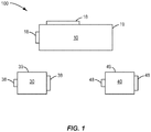
- Figure 1 schematically illustrates a tool100 that includes the base unit 10 and the first and second modules 30, 40.
- the base unit 10 includes a protective housing 19 that extends around the interior components.
- One or more mounting platforms 18 are positioned along the housing 19 to engage with the modules 30, 40.
- the platforms 18 may include one or more ports for operatively connecting the power and/or data communications with the modules 30, 40.
- Figure 1 includes a pair of platforms 18, although other embodiments may include a single platform 18 or three or more platforms 18. In embodiments with multiple platforms 18, each may be the same or they may be different.
- the platforms 18 also provide for physical engagement between the base unit 10 and the modules 30, 40.
- the platforms 18 may include various engagement features to connect with the modules 30, 40. Features include but are not limited to rails, indents, clips, and receptacles to receive fasteners.
- the platforms 18 may also include one or more ports for receiving and/or sending power and/or data to and from an upstream source. In one embodiment, the platforms 18 include a male/female attachment with the modules 30, 40.
- Each of the first and second modules 30, 40 are configured to attach to the base unit 10 at one of the platforms 18.
- Each of the modules 30, 40 includes a protective housing 39, 49 respectively that extend around the internal components.
- Each of the modules 30, 40 also includes one or more mounting platforms 38, 48 respectively that may each include one or more ports.
- the platforms 38, 48 provide for connecting with the base module 10 and connecting with upstream controllers such as through one or more cables.
- the platforms 38, 48 may include various features to provide for the connection, such as rails, indents, clips, and receptacles to receive fasteners, as well as to provide for operative connection for transferring power and/or data.
- FIG. 2 illustrates the modules 30, 40 that can be attached to the base unit 10.
- the second module 40 may be physically larger than the first module 30. This size difference is caused by the increased logic functionality in the second module 40.
- the modules 30, 40 also include outboard platforms 38, 48 for connecting with other components in the tooling system 200 for the transmission of data/power.
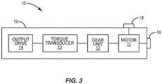
- FIG. 3 schematically illustrates the components of the base unit 10.
- the base unit 10 includes a motor 11, gear unit 12, torque transducer 13, and an output drive 14 that are positioned within an exterior housing 19.
- the motor 11 is electrically powered and produces a rotational force.
- the gear unit 12 couples the rotational force from the motor 11 to the output drive 14.
- the torque transducer 13 is operative to monitor the drive motor 11, the gear unit 12, and/or the output drive 14.
- the measurement transducer 13 may be configured to measure one or more parameters such as rotated angle, applied torque, or first derivatives of either of these parameters with respect to time.
- the output drive 14 may be straight, offset, or angled, as needed or desired.
- Figures 4 and 5 illustrate a first module 30 attached to the base unit 10 at the platform 18.
- the platforms 18, 38 are engaged together providing for a physical connection as well as transfer of data and/or power from the first module 30 to the base unit 10.
- first module 30 includes an outboard second platform 38 for attachment with cables to receive power and/or data from an upstream source.
- the connector interface 31 may also include an address device, for example in the form of rotary switches to send and receive signals from the control processor.
- a display 32 is provided on the first module 30 that includes a screen for indicating operational aspects of the tool 100.
- the display 32 may be a conventional liquid crystal display (LCD) or a touch screen display.
- One or more inputs may also be associated with the display 32 for the operator to toggle between viewing the various different operational features.
- LCD liquid crystal display
- the first module 30 does not include a servo amplifier. This is advantageous for use in conditions in which the working environment could damage the servo amplifier or otherwise prevent its proper functioning.
- the servo amplifier is positioned remote from the first module 30 within an upstream controller.
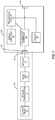
- Figure 6 illustrates the tool 100 that includes the base unit 10 and the first module 30 within a tooling system 200.
- a tool controller 91 controls the operation of the one or more tools 100.
- a system controller 90 controls and oversees the operation of the tooling system 200 through the tool controller 91.
- a robotic device 93 is configured to position the tools 100 at the desired operating position.
- a power source 92 provides power to one or more of the components in the system 200.
- the system 200 may include one or more different or identical tools 100 that may each be identical or may be different. In systems 200 with multiple tools 100, two or more of the tools 100 may be are grouped together in a tool cluster that mounts the tools 100 together on a frame. Cables 95 provide for power and/or data between the various components.
- the system controller 90 controls the overall operation of the system 200.
- the controller 20 is typically housed in a cabinet or the like at some distance from the tool 100.
- the system controller 90 may include a control circuit with one or more processors and/or microcontrollers that controls the overall operation according to program instructions stored in memory.
- Various types of memory may be included for storing program instructions and data needed for operation, and other memory for storing temporary data required to carry out its operations.
- the system controller 90 may also include a user interface that may include one or more user input devices such as a keypad, touchpad, function keys, scroll wheel, or other type of computer input device.
- a display may also be included, such as a conventional liquid crystal display (LCD) or touch screen display which also functions as a user input device.
- LCD liquid crystal display
- the tool controller 91 controls and monitors the operations of the tool 100.
- the controller 91 may include a control circuit and associated memory to act through program instructions to control the tool 100.
- Tool controller 91 may further include an interface and display for interaction with a user.
- the tool controller 91 is a separate component that is in communication with the system controller 90.
- Other embodiments may include the functionality of the tool controller 91 performed by the system controller 90.
- the tool controller 91 includes a servo amplifier 50 to monitor the tool 100.
- the servo amplifier 50 is operatively connected to the motor 11 in the base unit 10 to assist in its control.
- the servo amplifier 50 receives command signals regarding one or more of a desired velocity, torque, or position.
- the servo amplifier 50 monitors the status of the motor 11 and makes adjustments for the motor 11 to operate at the desired settings.
- the tool controller 91 is configured to include a separate servo amplifier 50 for each tool 100 in the tooling system 200.
- Figure 6 includes a single tool 100 and thus a single servo amplifier 50.
- the tool controller 91 may be housed in a cabinet that facilitates adding and removing servo amplifiers 50 as needed.
- a cabling system comprising cables 95 allows for communication between the components of the system 200.
- the cables 95 are configured for carrying various data signals.
- the system 200 communicates through a LAN.
- communications occur through a communications bus.
- the cabling system may further be configured to provide power from the power source 92 to the tool 100.
- the power source 92 may provide a single voltage, such as 24 VDC, or a plurality of voltages such as 380 VDC and 24 VDC depending on the type and number of tools 100.
- Figures 7 and 8 illustrate the tool 100 in a second tool configuration that includes the second module 40 attached to the base unit 10.
- the second module 40 includes a processing circuit 41, servo amplifier 50, a connector interface 43, and a display 44.
- the processing circuit 41 receives measurement data from the torque transducer 13 and processes the data and then supplies some or all of the processed data to the interface 43 for communication with the control processor 90 and/or tool processor 91.
- the servo amplifier 50 is positioned within the module 40 and performs the same process as the remotely-located servo amplifier 50 of the first configuration (i.e., receiving command signals regarding one or more of a desired velocity, torque, or position; monitoring the status of the motor 11 and making adjustments for the motor 11 to operate at the desired settings).
- the servo amplifier 50 also converts the analog signals into digital signals.
- the servo amplifier 50 may include a pair of circuit boards with a first configured as a measuring board for the various monitored aspects and a second board for power and logic.
- the servo amplifiers 50 used for the first and second modules 30, 40 perform similar or identical functions, but have different electrical and structural aspects.
- the display 44 may include indicators and/or a screen for indicating operational aspects of the tool 100.
- the display 44 may be the same as the display 32 described above.
- Display 44 may also include additional features such as one or more input devices for the operator to toggle between viewing the various different operational features.
- the connector interface 43 provides for supplying power from the power source 92 and transferring data to the control processor 90.
- the connector interface 43 may include one or more input and output ports, and may include an address device to send and receive signals from the control processor. In one embodiment, connector interfaces 43, 31 are the same.
- the second module 40 is configured to attach to the base unit 10 in a similar manner as the first module 30.
- This may include one or more platforms with mechanical fasteners, rails, locking detents, corresponding ramp surfaces, and male and female connectors that provide for a frictional fit.
- the attachment features are the same on the first and second attachments 30, 40.
- the attachments 30, 40 can be used interchangeably with the base unit 10. For example, a first job may require limited functionality for the tool 100 and thus the first module 30 may be attached to the base unit 10. Later, a second job may require additional functionality thus requiring the operator to remove the first module 30 and replace it with the second module 40.
- the second configuration may be used in a system similar to that used with the first configuration.
- the difference between the two configurations is the servo amplifier 50 is located in the second module 40 in the second configuration (and not in the tool controller 91). This provides for more of the logic of the tool 100 to be placed on the tool itself instead of being located at a remote location.
- the second module 40 may be constructed as a single unit, or may be constructed from multiple different units.
- Figures 7 and 8 include the second module 40 as a single unit.
- Figure 9 illustrates an embodiment with the second module 40 including a first unit 40a and a second unit 40b.
- the separate units 40a, 40b may each include separate attachment features for connecting to the base unit 10 and/or other units. Further, the separate units may each include separate housings.
- the various components of the second module 40 may be divided into the separate units in a variety of different manners.
- the servo amplifier 50 is in a first unit 40a, and a remainder of the components are housed in a second unit 40b.
- the base unit 10 may be configured to receive each of the first and second modules 30, 40 at the same platform 18. That is, the first module 30 is attached to the platform 18 of the base unit 10 in the first configuration 100, and the second module 40 is attached to the same platform 18 in the second configuration.
- the tool 100 may also be configured for the different modules 30, 40 to attach to different platforms 18 on the base unit 10.
- the first module 30 attaches to a first platform 18 in the first configuration
- the second module 40 attaches to a different second platform 18 in the second configuration.
- the first module 30 includes an exposed platform 38 with a single port for connecting with a cable 95 to the upstream components of the system 200.
- the single port provides for receiving power from the power supply 92 and communicating with at least one of the controllers 90, 91.
- a separate servo amplifier 50 is associated with each tool 100.
- the system 200 includes a separate dedicated servo amplifier 50 in the tool controller 91.
- multiple different tool controllers 91 may be employed to house the different servo amplifiers 50.
- Each of the tool controllers 91 may communicate with a common system controller 90.
- the second tool configuration positions a dedicated servo amplifier 50 within each of the modules 40 on the tool 100.
- the system 200 includes a single tool controller 91 that oversees multiple tools 100.
- the second tool configuration may also provide for the tools 100 to be connected together in a daisy-chain fashion.
- Figure 10 illustrates a configuration of the second module 40 that provides for this configuration by having first and second ports on the platform 38.
- the first port is for connecting to an upstream node (such as the tool controller 91 or an upstream tool 100) and is configured for power and data.
- the second port is connected to a downstream node (another tool 100) and likewise is configured for power and data.
- the tools 100 are connected together with a first cable 95 connected to the first port and a second cable 95 connected to the second port.
- the last tool 100 in the string i.e., the most-downstream tool 100
- power and data to downstream components travel through the upstream tools 100.
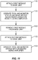
- Figure 11 illustrates a process of using the tool 100.
- the first module 30 is attached to the base unit 10 (block 1100).
- This first tool configuration may occur when the environment requires that the servo amplifier 50 be remotely located. In one embodiment, this occurs when the harmonics that occur during tool usage cause damage or reliability issues with the servo amplifier 50. This may also occur when the tool is used in a particularly non-conducive physical environment (e.g., extreme cold, heat, wet).
- the tool is operated (block 1101).
- the remote servo amplifier 50 at the tool controller 91 monitors the process and may make operating adjustments accordingly.
- the first module 30 is removed from the base unit 10 (block 1102).
- the second module 40 is then attached to the bae unit 10 (block 1103).
- the tool 100 is then operated in the second configuration with the servo amplifier 50 on-board (block 1104).
- the convertible design features of locating the servo amplifier depending upon the operational requirements of the tool have been described within the context of a spindle.
- the use of various electrically powered tightening spindles to help automate production processes is well known in the art.
- tightening spindles are commonly employed on an assembly line for the production of motor vehicles and the like where they are used to tighten screws or nuts.
- the convertible design features disclosed in this application are also applicable in other powered tools. Examples include but are not limited to robots, discrete automation, and manually-operated equipment.
- the tools and tooling systems described above include a cabling system to provide for communication links between the different components.
- One or more of the components may also include a wireless interface, such as through a Bluetooth interface or wireless local area network (WLAN) interface.
- the wireless communication components may be located in each of the first and second modules 30, 40. In another embodiment, these are located in the base unit 10.
- Some embodiments feature a system 200 that includes a combination of cabling and wireless communications.
Description
- This application claims priority to
U.S. Provisional patent Application Serial Number 62/092047 filed 15 December 2014 - The present application is directed to convertible power tools with a base unit that can receive different attachment modules that provide for different levels of functionality.
- In
US 7 090 031 B2 , a tightening spindle comprises a drive output; a housing adapted to detachably mount to a moving platform of a multi-tool processing station, with the housing substantially enclosing: at least one electric drive motor having an associated servo amplifier; a gear unit operatively connecting the drive motor to the drive output; a spindle measurement transducer operative to monitor at least one of the drive motor, the gear unit, and the drive output; and a measurement data processing unit in communication with the spindle measurement transducer. - There are many advantages for power tools that can be converted for use in different environments and for different working situations. One advantage is this type of tool is more cost effective. The tool can be converted and used in each situation, thus preventing the user from having to purchase separate tools to handle the different situations. Further, when the tool is in use, such as on an assembly line, it may be faster to convert the tool for different uses than to switch between first and second tools.
- Converting a single tool may allow for the tool to remain attached within a work area, such as within tool cluster or remain attached to a robotic device. Conversely, detaching the first tool, removing it from the work area, inserting a second tool, and attaching the second tool at the work area may be a lengthy process. The tool may also be located at a physically difficult position for an operator to reach. Converting the single tool may be relatively easy as compared to removing and replacing the tools.
- The present application is directed to a convertible tooling system that includes a common base unit and multiple different interchangeable attachments. Each of the attachments includes different components and offers different capabilities for operation of the base unit. The convertible design provides for interchangeability of components to accommodate the needs of the user.
- The invention is directed to a tool that can be converted to be used in one of a first configuration and a second configuration. The tool includes a base unit, a servo-free module, and a servo amplifier module. The base unit receives power and data communications from a remote source. The base unit includes a motor an output drive that is driven by the motor, and a housing with a mounting platform and that extends around the motor and the output drive. The servo-free module includes a first connector interface, and a first housing that extends around the first connector interface and that includes a first mount. The servo-free module does not include a servo amplifier. The servo amplifier module includes a servo amplifier, a processing circuit, a second connector interface, and a second housing that extends around the servo amplifier, the processing circuit, and the second connector interface. The second housing includes a second mount. The mounting platform of the base unit is configured to removably connect at one time to the servo-free module or the servo amplifier module. A first configuration includes the servo-free module physically and electrically removably connected to the base unit with the power and data communications from the remote source that are received at the base unit passing through the servo-free module. A second configuration includes the servo amplifier module physically and electrically removably connected to the base unit with the power and data communications from the remote source that are received at the base unit passing through the servo amplifier module.
- The tool may also include a base port positioned at the mounting platform, a first port positioned at the first mount, and a second port positioned at the second mount. The first configuration includes the first port physically and electrically engaging with the base port of the base unit, and the second configuration including the second port physically and electrically engaging with the base port of the base unit.
- The tool may include that the base unit further includes a torque transducer and a gear unit.
- The tool may include that each of the servo-free module and the servo module include a display screen.
- The tool may include that the motor of the base unit is configured to be adjustable based on signals received from a remote servo amplifier.
- The tool may include that the servo amplifier includes an analog-to-digital converter.
- The invention is also directed to a method of operating a tool. The method includes: electrically and physically attaching a servo-free module to a base unit with the servo-free module positioned at a mounting position on the base unit and that the servo-free module does not include a servo amplifier; operating the tool in a first configuration while power and data from a remote source pass through the servo-free module to the base unit; removing the servo-free module from the base unit; electrically and physically attaching a servo module at the mounting position on the base unit where the servo-free module was previously attached with the servo module comprising a servo amplifier; operating the tool in a second configuration while power and data from the remote source pass through the servo module to the base unit; and monitoring a motor in the base unit with the servo amplifier in the servo module while operating the tool in the second configuration.
- The method may further include engaging a base port on the base unit with a first port on the servo-free module while the tool is in the first configuration and with a second port on the servo module while the tool is in the second configuration.
- The method may further include performing analog-to-digital conversions of motor signals at the servo amplifier.
- The method may further include attaching the servo module to a downstream tool and transferring power and data information through the servo module to the downstream tool.
- The method may further include contacting a first housing of the servo-free module against a housing of the base unit in the first configuration and contacting a second housing of the servo module against the housing of the base unit in the second configuration.
- The method may include deactivating the base unit by detaching both the servo-free module and the servo module from the base unit.
- The method may include attaching a power and data cable to the servo-free module in the first configuration and to the servo module in the second configuration.
- The method may include attaching the second module to the base unit and positioning the servo amplifier on the exterior of the housing of the base unit.
- One embodiment is directed to a convertible tooling system that includes a base unit with a motor, gearing, an output drive, and a receptacle. The system also includes a first attachment configured to be attached to the base unit at the receptacle. The first attachment includes a connector interface and a display. The system also includes a second attachment configured to be attached to the base unit at the receptacle. The second attachment includes a processing circuit, a servo amplifier, a transducer, a connector interface, and a display. The receptacle on the base unit is configured to receive just one of the first and second attachments at a time.
- The receptacle may include a single mounting position configured to receive one of the first and the second attachments.
- The receptacle may include multiple mounting positions that are each configured to receive at least one of the first and second attachments.
- Another embodiment is directed to a convertible tooling system and includes a base unit including a motor and a receptacle. The system also includes a first attachment configured to be attached to the base unit at the receptacle. The first attachment includes a connector interface to send and receive signals from the motor and a display. The system also includes a second attachment configured to be attached to the base unit at the receptacle. The second attachment includes a processing circuit and a servo amplifier configured to send and receive signals with the motor and control the operation of the motor. The receptacle is configured to receive just one of the first and second attachments at a time.
- Another embodiment is directed to a method of using a convertible tooling system. The method includes: attaching a first attachment unit to a base unit with the first attachment including a display to display information regarding operation of a motor in the base unit without controlling operation of the motor; detaching the first attachment unit from the base unit; attaching a second attachment unit to the base unit with the second attachment including a servo amplifier configured to control operation of the motor.
- The various aspects of the various embodiments may be used alone or in any combination, as is desired.
-
-
Figure 1 is a schematic view of a tool in a disassembled state that includes a base unit that is attachable to a first module and a second module. -
Figure 2 is a side view of a tool in a disassembled state including a base unit, a first module, and a second module. -
Figure 3 is a schematic view of a base unit. -
Figure 4 is a schematic view of a tool in a first configuration with a base unit attached to a first module. -
Figure 5 is a side view of the tool ofFigure 4 . -
Figure 6 is a schematic view of a tool positioned within a tooling system. -
Figure 7 is a schematic view of a tool in a second configuration with a base unit attached to a second module. -
Figure 8 is a perspective view of a tool ofFigure 7 . -
Figure 9 is a schematic view of a tool in a second configuration with the second module including first and second sections. -
Figure 10 is a partial perspective view of tool in a second configuration with a second module attached to a base unit. -
Figure 11 is a process diagram of a method of using a tool with first and second modules. - The present application is directed to a convertible power tool that can operate in first and second configurations. The convertible power tool includes a base unit configured to receive at one time either a first module or a second module. The different modules provide for different levels of tool functionality. The first module includes one or more components that provide for a first level of functionality. The second module includes one or more components that provide for an advanced second level of functionality. Each of the base unit and first and second modules include interfaces that provide for physical engagement as well as power/data engagement. In use, one of the first and second modules is connected to the base unit to provide for the desired functionality incorporated with the tool. The tool may also be converted by removing the attached module and replacing it with the other module thus providing for a different functionality level.
-
Figure 1 schematically illustrates a tool100 that includes thebase unit 10 and the first andsecond modules base unit 10 includes aprotective housing 19 that extends around the interior components. One ormore mounting platforms 18 are positioned along thehousing 19 to engage with themodules platforms 18 may include one or more ports for operatively connecting the power and/or data communications with themodules Figure 1 includes a pair ofplatforms 18, although other embodiments may include asingle platform 18 or three ormore platforms 18. In embodiments withmultiple platforms 18, each may be the same or they may be different. Theplatforms 18 also provide for physical engagement between thebase unit 10 and themodules - The
platforms 18 may include various engagement features to connect with themodules platforms 18 may also include one or more ports for receiving and/or sending power and/or data to and from an upstream source. In one embodiment, theplatforms 18 include a male/female attachment with themodules - Each of the first and
second modules base unit 10 at one of theplatforms 18. Each of themodules protective housing modules more mounting platforms platforms base module 10 and connecting with upstream controllers such as through one or more cables. Theplatforms -
Figure 2 illustrates themodules base unit 10. Thesecond module 40 may be physically larger than thefirst module 30. This size difference is caused by the increased logic functionality in thesecond module 40. As illustrated inFigure 2 , themodules outboard platforms tooling system 200 for the transmission of data/power. -
Figure 3 schematically illustrates the components of thebase unit 10. Thebase unit 10 includes amotor 11,gear unit 12,torque transducer 13, and anoutput drive 14 that are positioned within anexterior housing 19. Themotor 11 is electrically powered and produces a rotational force. Thegear unit 12 couples the rotational force from themotor 11 to theoutput drive 14. Thetorque transducer 13 is operative to monitor thedrive motor 11, thegear unit 12, and/or theoutput drive 14. Themeasurement transducer 13 may be configured to measure one or more parameters such as rotated angle, applied torque, or first derivatives of either of these parameters with respect to time. The output drive 14 may be straight, offset, or angled, as needed or desired. -
Figures 4 and5 illustrate afirst module 30 attached to thebase unit 10 at theplatform 18. Theplatforms first module 30 to thebase unit 10. Further,first module 30 includes an outboardsecond platform 38 for attachment with cables to receive power and/or data from an upstream source. Theconnector interface 31 may also include an address device, for example in the form of rotary switches to send and receive signals from the control processor. Adisplay 32 is provided on thefirst module 30 that includes a screen for indicating operational aspects of thetool 100. Thedisplay 32 may be a conventional liquid crystal display (LCD) or a touch screen display. One or more inputs may also be associated with thedisplay 32 for the operator to toggle between viewing the various different operational features. - The
first module 30 does not include a servo amplifier. This is advantageous for use in conditions in which the working environment could damage the servo amplifier or otherwise prevent its proper functioning. Thus, the servo amplifier is positioned remote from thefirst module 30 within an upstream controller. -
Figure 6 illustrates thetool 100 that includes thebase unit 10 and thefirst module 30 within atooling system 200. Atool controller 91 controls the operation of the one ormore tools 100. Asystem controller 90 controls and oversees the operation of thetooling system 200 through thetool controller 91. Arobotic device 93 is configured to position thetools 100 at the desired operating position. Apower source 92 provides power to one or more of the components in thesystem 200. Thesystem 200 may include one or more different oridentical tools 100 that may each be identical or may be different. Insystems 200 withmultiple tools 100, two or more of thetools 100 may be are grouped together in a tool cluster that mounts thetools 100 together on a frame.Cables 95 provide for power and/or data between the various components. - The
system controller 90 controls the overall operation of thesystem 200. The controller 20 is typically housed in a cabinet or the like at some distance from thetool 100. Thesystem controller 90 may include a control circuit with one or more processors and/or microcontrollers that controls the overall operation according to program instructions stored in memory. Various types of memory may be included for storing program instructions and data needed for operation, and other memory for storing temporary data required to carry out its operations. Thesystem controller 90 may also include a user interface that may include one or more user input devices such as a keypad, touchpad, function keys, scroll wheel, or other type of computer input device. A display may also be included, such as a conventional liquid crystal display (LCD) or touch screen display which also functions as a user input device. - The
tool controller 91 controls and monitors the operations of thetool 100. Thecontroller 91 may include a control circuit and associated memory to act through program instructions to control thetool 100.Tool controller 91 may further include an interface and display for interaction with a user. In one embodiment as illustrated inFigure 6 , thetool controller 91 is a separate component that is in communication with thesystem controller 90. Other embodiments may include the functionality of thetool controller 91 performed by thesystem controller 90. - The
tool controller 91 includes aservo amplifier 50 to monitor thetool 100. Theservo amplifier 50 is operatively connected to themotor 11 in thebase unit 10 to assist in its control. Theservo amplifier 50 receives command signals regarding one or more of a desired velocity, torque, or position. Theservo amplifier 50 monitors the status of themotor 11 and makes adjustments for themotor 11 to operate at the desired settings. Thetool controller 91 is configured to include aseparate servo amplifier 50 for eachtool 100 in thetooling system 200.Figure 6 includes asingle tool 100 and thus asingle servo amplifier 50. Thetool controller 91 may be housed in a cabinet that facilitates adding and removingservo amplifiers 50 as needed. - A cabling
system comprising cables 95 allows for communication between the components of thesystem 200. Thecables 95 are configured for carrying various data signals. In one embodiment, thesystem 200 communicates through a LAN. In one embodiment, communications occur through a communications bus. The cabling system may further be configured to provide power from thepower source 92 to thetool 100. Thepower source 92 may provide a single voltage, such as 24 VDC, or a plurality of voltages such as 380 VDC and 24 VDC depending on the type and number oftools 100. -
Figures 7 and8 illustrate thetool 100 in a second tool configuration that includes thesecond module 40 attached to thebase unit 10. Thesecond module 40 includes aprocessing circuit 41,servo amplifier 50, aconnector interface 43, and adisplay 44. - The
processing circuit 41 receives measurement data from thetorque transducer 13 and processes the data and then supplies some or all of the processed data to theinterface 43 for communication with thecontrol processor 90 and/ortool processor 91. Theservo amplifier 50 is positioned within themodule 40 and performs the same process as the remotely-locatedservo amplifier 50 of the first configuration (i.e., receiving command signals regarding one or more of a desired velocity, torque, or position; monitoring the status of themotor 11 and making adjustments for themotor 11 to operate at the desired settings). Theservo amplifier 50 also converts the analog signals into digital signals. Theservo amplifier 50 may include a pair of circuit boards with a first configured as a measuring board for the various monitored aspects and a second board for power and logic. Theservo amplifiers 50 used for the first andsecond modules - The
display 44 may include indicators and/or a screen for indicating operational aspects of thetool 100. Thedisplay 44 may be the same as thedisplay 32 described above.Display 44 may also include additional features such as one or more input devices for the operator to toggle between viewing the various different operational features. Theconnector interface 43 provides for supplying power from thepower source 92 and transferring data to thecontrol processor 90. Theconnector interface 43 may include one or more input and output ports, and may include an address device to send and receive signals from the control processor. In one embodiment, connector interfaces 43, 31 are the same. - The
second module 40 is configured to attach to thebase unit 10 in a similar manner as thefirst module 30. This may include one or more platforms with mechanical fasteners, rails, locking detents, corresponding ramp surfaces, and male and female connectors that provide for a frictional fit. In one embodiment, the attachment features are the same on the first andsecond attachments attachments base unit 10. For example, a first job may require limited functionality for thetool 100 and thus thefirst module 30 may be attached to thebase unit 10. Later, a second job may require additional functionality thus requiring the operator to remove thefirst module 30 and replace it with thesecond module 40. - The second configuration may be used in a system similar to that used with the first configuration. The difference between the two configurations is the
servo amplifier 50 is located in thesecond module 40 in the second configuration (and not in the tool controller 91). This provides for more of the logic of thetool 100 to be placed on the tool itself instead of being located at a remote location. - One embodiment of a second configuration of a tool is disclosed in
U.S. Patent No. 7,090,031 . - The
second module 40 may be constructed as a single unit, or may be constructed from multiple different units.Figures 7 and8 include thesecond module 40 as a single unit.Figure 9 illustrates an embodiment with thesecond module 40 including afirst unit 40a and asecond unit 40b. Theseparate units base unit 10 and/or other units. Further, the separate units may each include separate housings. The various components of thesecond module 40 may be divided into the separate units in a variety of different manners. In one embodiment, theservo amplifier 50 is in afirst unit 40a, and a remainder of the components are housed in asecond unit 40b. - The
base unit 10 may be configured to receive each of the first andsecond modules same platform 18. That is, thefirst module 30 is attached to theplatform 18 of thebase unit 10 in thefirst configuration 100, and thesecond module 40 is attached to thesame platform 18 in the second configuration. Thetool 100 may also be configured for thedifferent modules different platforms 18 on thebase unit 10. Thus, thefirst module 30 attaches to afirst platform 18 in the first configuration, and thesecond module 40 attaches to a differentsecond platform 18 in the second configuration. - As illustrated in
Figure 5 with the first tool configuration, thefirst module 30 includes an exposedplatform 38 with a single port for connecting with acable 95 to the upstream components of thesystem 200. The single port provides for receiving power from thepower supply 92 and communicating with at least one of thecontrollers separate servo amplifier 50 is associated with eachtool 100. Thus, for eachtool 100, thesystem 200 includes a separatededicated servo amplifier 50 in thetool controller 91. In relativelylarge tooling systems 200 with a large number oftools 100, multipledifferent tool controllers 91 may be employed to house thedifferent servo amplifiers 50. Each of thetool controllers 91 may communicate with acommon system controller 90. - The second tool configuration positions a
dedicated servo amplifier 50 within each of themodules 40 on thetool 100. Thesystem 200 includes asingle tool controller 91 that overseesmultiple tools 100. - The second tool configuration may also provide for the
tools 100 to be connected together in a daisy-chain fashion.Figure 10 illustrates a configuration of thesecond module 40 that provides for this configuration by having first and second ports on theplatform 38. The first port is for connecting to an upstream node (such as thetool controller 91 or an upstream tool 100) and is configured for power and data. The second port is connected to a downstream node (another tool 100) and likewise is configured for power and data. Thetools 100 are connected together with afirst cable 95 connected to the first port and asecond cable 95 connected to the second port. Thelast tool 100 in the string (i.e., the most-downstream tool 100) may include a termination cap on the second port to prevent farther downstream transfer of power and/or data. Thus, power and data to downstream components travel through theupstream tools 100. -
Figure 11 illustrates a process of using thetool 100. Initially, thefirst module 30 is attached to the base unit 10 (block 1100). This first tool configuration may occur when the environment requires that theservo amplifier 50 be remotely located. In one embodiment, this occurs when the harmonics that occur during tool usage cause damage or reliability issues with theservo amplifier 50. This may also occur when the tool is used in a particularly non-conducive physical environment (e.g., extreme cold, heat, wet). Once thefirst module 30 is attached, the tool is operated (block 1101). Theremote servo amplifier 50 at thetool controller 91 monitors the process and may make operating adjustments accordingly. - Once the operation is complete, the
first module 30 is removed from the base unit 10 (block 1102). Thesecond module 40 is then attached to the bae unit 10 (block 1103). Thetool 100 is then operated in the second configuration with theservo amplifier 50 on-board (block 1104). - The convertible design features of locating the servo amplifier depending upon the operational requirements of the tool have been described within the context of a spindle. The use of various electrically powered tightening spindles to help automate production processes is well known in the art. For example, such tightening spindles are commonly employed on an assembly line for the production of motor vehicles and the like where they are used to tighten screws or nuts. The convertible design features disclosed in this application are also applicable in other powered tools. Examples include but are not limited to robots, discrete automation, and manually-operated equipment.
- The tools and tooling systems described above include a cabling system to provide for communication links between the different components. One or more of the components may also include a wireless interface, such as through a Bluetooth interface or wireless local area network (WLAN) interface. The wireless communication components may be located in each of the first and
second modules base unit 10. Some embodiments feature asystem 200 that includes a combination of cabling and wireless communications. - Spatially relative terms such as "under", "below", "lower", "over", "upper", and the like, are used for ease of description to explain the positioning of one element relative to a second element. These terms are intended to encompass different orientations of the device in addition to different orientations than those depicted in the figures. Further, terms such as "first", "second", and the like, are also used to describe various elements, regions, sections, etc. and are also not intended to be limiting. Like terms refer to like elements throughout the description.
- As used herein, the terms "having", "containing", "including", "comprising" and the like are open ended terms that indicate the presence of stated elements or features, but do not preclude additional elements or features. The articles "a", "an" and "the" are intended to include the plural as well as the singular, unless the context clearly indicates otherwise.
- The present invention may be carried out in other specific ways than those herein set forth without departing from the scope and essential characteristics of the invention.
Claims (14)
- A tool that can be converted to be used in one of a first configuration and a second configuration, the tool comprising:a base unit (10) that receives power and data communications from a remote source, the base unit (10) comprising:a motor (11);an output drive (14) that is driven by the motor (11); anda housing (19) that extends around the motor (11) and the output drive (14), the housing (19) comprising a mounting platform (18);a servo-free module (30) that does not include a servo amplifier, the servo-free module comprising:a first connector interface (31); anda first housing that extends around the first connector interface (31), the first housing comprising a first mount (38);a servo amplifier module (40) comprising:a servo amplifier (50) configured to monitor the status of the motor (11) and to make adjustments for the motor (11) to operate at the desired settings;a processing circuit (41);a second connector interface (43); anda second housing that extends around the servo amplifier (50), the processing circuit (41), and the second connector interface (43), the second housing comprising a second mount (48);the mounting platform (18) of the base unit (10) configured to removably connect at a time to one of the servo-free module (30) and the servo amplifier module (40);a first configuration comprising the servo-free module (30) physically and electrically removably connected to the base unit (10) with the power and data communications from the remote source that are received at the base unit (10) passing through the servo-free module (30);a second configuration comprising the servo amplifier module (40) physically and electrically removably connected to the base unit (10) with the power and data communications from the remote source that are received at the base unit (10) passing through the servo amplifier module (40).
- The tool of claim 1, further comprising a base port positioned at the mounting platform (18), a first port positioned at the first mount (38), and a second port positioned at the second mount (48), the first configuration comprising the first port physically and electrically engaging with the base port of the base unit (10), and the second configuration comprising the second port physically and electrically engaging with the base port of the base unit (10).
- The tool of claim 1, wherein the base unit (10) further comprises a torque transducer (13) and a gear unit (12).
- The tool of claim 1, wherein each of the servo-free module (30) and the servo module (40) comprise a display screen (32,44).
- The tool of claim 1, wherein the motor (11) of the base unit (10) is configured to be adjustable based on signals received from a remote servo amplifier.
- The tool of claim 1, wherein the servo amplifier (50) comprises an analog-to-digital converter.
- A method of operating a tool according to one of the preceding claims, the method comprising:electrically and physically attaching a servo-free module (30) to a base unit (10) with the servo-free module (30) positioned at a mounting position (18) on the base unit (10), the servo-free module (30) does not include a servo amplifier;operating the tool in a first configuration while power and data from a remote source pass through the servo-free module (30) to the base unit (10);removing the servo-free module (30) from the base unit (10);electrically and physically attaching a servo module (40) at the mounting position (18) on the base unit (10) where the servo-free module (30) was previously attached, the servo module (40) comprising a servo amplifier (50);operating the tool in a second configuration while power and data from the remote source pass through the servo module (40) to the base unit (10); andmonitoring a motor (11) in the base unit (10) with the servo amplifier (50) in the servo module (40) while operating the tool in the second configuration.
- The method of claim 7, further comprising engaging a base port on the base unit (10) with a first port on the servo-free module (30) while the tool is in the first configuration and with a second port on the servo module (40) while the tool is in the second configuration.
- The method of claim 7, further comprising performing analog-to-digital conversions of motor signals at the servo amplifier (50).
- The method of claim 7, further comprising attaching the servo module (40) to a downstream tool and transferring power and data information through the servo module (40) to the downstream tool.
- The method of claim 7, further comprising contacting a first housing of the servo-free module (30) against a housing of the base unit (10) in the first configuration and contacting a second housing of the servo module (40) against the housing of the base unit (10) in the second configuration.
- The method of claim 7, further comprising deactivating the base unit (10) by detaching both the servo-free module (30) and the servo module (40) from the base unit (10).
- The method of claim 7, further comprising attaching a power and data cable to the servo-free module (30) in the first configuration and to the servo module (40) in the second configuration.
- The method of claim 7, further comprising attaching the servo module (40) to the base unit (10) and positioning the servo amplifier (50) on the exterior of the housing of the base unit (10).
Applications Claiming Priority (2)
| Application Number | Priority Date | Filing Date | Title |
|---|---|---|---|
| US201462092047P | 2014-12-15 | 2014-12-15 | |
| PCT/US2015/065560 WO2016100213A1 (en) | 2014-12-15 | 2015-12-14 | Convertible intelligent power tool |
Publications (2)
| Publication Number | Publication Date |
|---|---|
| EP3234708A1 EP3234708A1 (en) | 2017-10-25 |
| EP3234708B1 true EP3234708B1 (en) | 2021-11-17 |
Family
ID=55070171
Family Applications (1)
| Application Number | Title | Priority Date | Filing Date |
|---|---|---|---|
| EP15820392.7A Active EP3234708B1 (en) | 2014-12-15 | 2015-12-14 | Convertible intelligent power tool |
Country Status (5)
| Country | Link |
|---|---|
| US (1) | US10864623B2 (en) |
| EP (1) | EP3234708B1 (en) |
| CN (1) | CN107407925B (en) |
| ES (1) | ES2899891T3 (en) |
| WO (1) | WO2016100213A1 (en) |
Families Citing this family (7)
| Publication number | Priority date | Publication date | Assignee | Title |
|---|---|---|---|---|
| US11034003B2 (en) | 2016-12-02 | 2021-06-15 | Snap-On Incorporated | Holding tool |
| GB2560402B (en) * | 2016-12-02 | 2019-07-03 | Snap On Tools Corp | Holding tool |
| DE102017222869A1 (en) * | 2016-12-19 | 2018-06-21 | Robert Bosch Gmbh | Drive base module |
| US20180178366A1 (en) * | 2016-12-23 | 2018-06-28 | Andrei Matei | Modular tool system |
| US20190217460A1 (en) * | 2018-01-18 | 2019-07-18 | Ingersoll-Rand Company | Add-on user interface module for precision power tools |
| US20210205976A1 (en) * | 2020-01-06 | 2021-07-08 | Robbox Inc. | Apparatus and method of an interactive power tool |
| US11698620B2 (en) | 2021-01-27 | 2023-07-11 | Apex Brands, Inc. | Spindle and spindle system with logic supply bus fault diagnostics |
Family Cites Families (9)
| Publication number | Priority date | Publication date | Assignee | Title |
|---|---|---|---|---|
| US5315501A (en) * | 1992-04-03 | 1994-05-24 | The Stanley Works | Power tool compensator for torque overshoot |
| US5637968A (en) * | 1993-10-25 | 1997-06-10 | The Stanley Works | Power tool with automatic downshift feature |
| EP1579959B1 (en) * | 2004-03-22 | 2008-12-10 | Cooper Power Tools GmbH & Co. | Intelligent tightening spindle with integrated measurement transducer, servo amplifier, and data processing unit |
| JP5431006B2 (en) * | 2009-04-16 | 2014-03-05 | Tone株式会社 | Wireless data transmission / reception system |
| US8468231B1 (en) * | 2010-04-16 | 2013-06-18 | The Boeing Company | Architecture for network-enabled tools |
| EP2731517A2 (en) * | 2011-07-11 | 2014-05-21 | Medical Vision Research & Development AB | Status control for electrically powered surgical tool systems |
| US9776315B2 (en) * | 2011-11-11 | 2017-10-03 | Black & Decker Inc. | Power tool having interchangeable tool heads with an independent accessory switch |
| US9022135B2 (en) * | 2012-10-02 | 2015-05-05 | Stanley Black & Decker, Inc. | Torque-applying tool and torque controller therefor |
| WO2015061370A1 (en) * | 2013-10-21 | 2015-04-30 | Milwaukee Electric Tool Corporation | Adapter for power tool devices |
-
2015
- 2015-12-14 US US15/534,722 patent/US10864623B2/en active Active
- 2015-12-14 WO PCT/US2015/065560 patent/WO2016100213A1/en active Application Filing
- 2015-12-14 ES ES15820392T patent/ES2899891T3/en active Active
- 2015-12-14 EP EP15820392.7A patent/EP3234708B1/en active Active
- 2015-12-14 CN CN201580076172.XA patent/CN107407925B/en active Active
Non-Patent Citations (1)
| Title |
|---|
| None * |
Also Published As
| Publication number | Publication date |
|---|---|
| CN107407925B (en) | 2019-08-20 |
| WO2016100213A1 (en) | 2016-06-23 |
| US10864623B2 (en) | 2020-12-15 |
| CN107407925A (en) | 2017-11-28 |
| ES2899891T3 (en) | 2022-03-15 |
| US20170368674A1 (en) | 2017-12-28 |
| EP3234708A1 (en) | 2017-10-25 |
Similar Documents
| Publication | Publication Date | Title |
|---|---|---|
| EP3234708B1 (en) | Convertible intelligent power tool | |
| US11485010B2 (en) | Adapter system for connecting the last element of a kinematic chain to a handling device | |
| EP2829369B1 (en) | Robot and manufacturing method of the same | |
| CN104802033B (en) | Fixed cable-free tool | |
| US20100096151A1 (en) | Portable power tool with wireless communication with a stationary control unit | |
| EP3062960B1 (en) | Tooling system with electronic signal maintenance | |
| KR20140038329A (en) | Industrial robot having electronic drive devices distributed on the robot structure | |
| EP2821178A1 (en) | Robotic system | |
| US11077549B2 (en) | Robot and robot system | |
| US20220009107A1 (en) | System for radio connection of an assembly to a controller | |
| US7630775B2 (en) | Control system and method for controlling one or several manipulators | |
| DE102010044823B4 (en) | screw spindle | |
| US20100179706A1 (en) | Systems, Methods, and Apparatus for Providing Continuous Power to a Fixture in a Manufacturing Process | |
| EP1579959B1 (en) | Intelligent tightening spindle with integrated measurement transducer, servo amplifier, and data processing unit | |
| US10286554B2 (en) | Electric apparatus mounting device and method | |
| JP2019104099A (en) | Robot hand and control method for robot hand | |
| KR20130010183A (en) | Robot system using power line communication | |
| EP3389929A1 (en) | A system for pre-tensioning a joint comprising a number of threaded elements | |
| CN113084407B (en) | Intelligent welding production line for trolley frame and partition plate | |
| WO2007107277A1 (en) | Manipulator, for example an industrial robot, and drive device for a manipulator | |
| CN219269258U (en) | Switch board convenient to integrate | |
| JP2008250691A (en) | Cable wiring-less system with equipment in programmable controller | |
| JP6764688B2 (en) | How to update the controller | |
| CN217046391U (en) | Intelligent hot-line work robot | |
| US11897131B2 (en) | Actuator |
Legal Events
| Date | Code | Title | Description |
|---|---|---|---|
| STAA | Information on the status of an ep patent application or granted ep patent |
Free format text: STATUS: THE INTERNATIONAL PUBLICATION HAS BEEN MADE |
|
| PUAI | Public reference made under article 153(3) epc to a published international application that has entered the european phase |
Free format text: ORIGINAL CODE: 0009012 |
|
| STAA | Information on the status of an ep patent application or granted ep patent |
Free format text: STATUS: REQUEST FOR EXAMINATION WAS MADE |
|
| 17P | Request for examination filed |
Effective date: 20170612 |
|
| AK | Designated contracting states |
Kind code of ref document: A1 Designated state(s): AL AT BE BG CH CY CZ DE DK EE ES FI FR GB GR HR HU IE IS IT LI LT LU LV MC MK MT NL NO PL PT RO RS SE SI SK SM TR |
|
| AX | Request for extension of the european patent |
Extension state: BA ME |
|
| DAV | Request for validation of the european patent (deleted) | ||
| DAX | Request for extension of the european patent (deleted) | ||
| STAA | Information on the status of an ep patent application or granted ep patent |
Free format text: STATUS: EXAMINATION IS IN PROGRESS |
|
| 17Q | First examination report despatched |
Effective date: 20190314 |
|
| STAA | Information on the status of an ep patent application or granted ep patent |
Free format text: STATUS: EXAMINATION IS IN PROGRESS |
|
| GRAP | Despatch of communication of intention to grant a patent |
Free format text: ORIGINAL CODE: EPIDOSNIGR1 |
|
| STAA | Information on the status of an ep patent application or granted ep patent |
Free format text: STATUS: GRANT OF PATENT IS INTENDED |
|
| RIC1 | Information provided on ipc code assigned before grant |
Ipc: G05B 19/409 20060101AFI20210519BHEP Ipc: B25F 3/00 20060101ALI20210519BHEP |
|
| INTG | Intention to grant announced |
Effective date: 20210602 |
|
| GRAS | Grant fee paid |
Free format text: ORIGINAL CODE: EPIDOSNIGR3 |
|
| GRAA | (expected) grant |
Free format text: ORIGINAL CODE: 0009210 |
|
| STAA | Information on the status of an ep patent application or granted ep patent |
Free format text: STATUS: THE PATENT HAS BEEN GRANTED |
|
| AK | Designated contracting states |
Kind code of ref document: B1 Designated state(s): AL AT BE BG CH CY CZ DE DK EE ES FI FR GB GR HR HU IE IS IT LI LT LU LV MC MK MT NL NO PL PT RO RS SE SI SK SM TR |
|
| REG | Reference to a national code |
Ref country code: GB Ref legal event code: FG4D |
|
| REG | Reference to a national code |
Ref country code: IE Ref legal event code: FG4D |
|
| REG | Reference to a national code |
Ref country code: DE Ref legal event code: R096 Ref document number: 602015075118 Country of ref document: DE |
|
| REG | Reference to a national code |
Ref country code: AT Ref legal event code: REF Ref document number: 1448573 Country of ref document: AT Kind code of ref document: T Effective date: 20211215 |
|
| REG | Reference to a national code |
Ref country code: LT Ref legal event code: MG9D |
|
| REG | Reference to a national code |
Ref country code: ES Ref legal event code: FG2A Ref document number: 2899891 Country of ref document: ES Kind code of ref document: T3 Effective date: 20220315 |
|
| REG | Reference to a national code |
Ref country code: NL Ref legal event code: MP Effective date: 20211117 |
|
| REG | Reference to a national code |
Ref country code: AT Ref legal event code: MK05 Ref document number: 1448573 Country of ref document: AT Kind code of ref document: T Effective date: 20211117 |
|
| PG25 | Lapsed in a contracting state [announced via postgrant information from national office to epo] |
Ref country code: RS Free format text: LAPSE BECAUSE OF FAILURE TO SUBMIT A TRANSLATION OF THE DESCRIPTION OR TO PAY THE FEE WITHIN THE PRESCRIBED TIME-LIMIT Effective date: 20211117 Ref country code: LT Free format text: LAPSE BECAUSE OF FAILURE TO SUBMIT A TRANSLATION OF THE DESCRIPTION OR TO PAY THE FEE WITHIN THE PRESCRIBED TIME-LIMIT Effective date: 20211117 Ref country code: FI Free format text: LAPSE BECAUSE OF FAILURE TO SUBMIT A TRANSLATION OF THE DESCRIPTION OR TO PAY THE FEE WITHIN THE PRESCRIBED TIME-LIMIT Effective date: 20211117 Ref country code: BG Free format text: LAPSE BECAUSE OF FAILURE TO SUBMIT A TRANSLATION OF THE DESCRIPTION OR TO PAY THE FEE WITHIN THE PRESCRIBED TIME-LIMIT Effective date: 20220217 Ref country code: AT Free format text: LAPSE BECAUSE OF FAILURE TO SUBMIT A TRANSLATION OF THE DESCRIPTION OR TO PAY THE FEE WITHIN THE PRESCRIBED TIME-LIMIT Effective date: 20211117 |
|
| PG25 | Lapsed in a contracting state [announced via postgrant information from national office to epo] |
Ref country code: IS Free format text: LAPSE BECAUSE OF FAILURE TO SUBMIT A TRANSLATION OF THE DESCRIPTION OR TO PAY THE FEE WITHIN THE PRESCRIBED TIME-LIMIT Effective date: 20220317 Ref country code: SE Free format text: LAPSE BECAUSE OF FAILURE TO SUBMIT A TRANSLATION OF THE DESCRIPTION OR TO PAY THE FEE WITHIN THE PRESCRIBED TIME-LIMIT Effective date: 20211117 Ref country code: PT Free format text: LAPSE BECAUSE OF FAILURE TO SUBMIT A TRANSLATION OF THE DESCRIPTION OR TO PAY THE FEE WITHIN THE PRESCRIBED TIME-LIMIT Effective date: 20220317 Ref country code: PL Free format text: LAPSE BECAUSE OF FAILURE TO SUBMIT A TRANSLATION OF THE DESCRIPTION OR TO PAY THE FEE WITHIN THE PRESCRIBED TIME-LIMIT Effective date: 20211117 Ref country code: NO Free format text: LAPSE BECAUSE OF FAILURE TO SUBMIT A TRANSLATION OF THE DESCRIPTION OR TO PAY THE FEE WITHIN THE PRESCRIBED TIME-LIMIT Effective date: 20220217 Ref country code: NL Free format text: LAPSE BECAUSE OF FAILURE TO SUBMIT A TRANSLATION OF THE DESCRIPTION OR TO PAY THE FEE WITHIN THE PRESCRIBED TIME-LIMIT Effective date: 20211117 Ref country code: LV Free format text: LAPSE BECAUSE OF FAILURE TO SUBMIT A TRANSLATION OF THE DESCRIPTION OR TO PAY THE FEE WITHIN THE PRESCRIBED TIME-LIMIT Effective date: 20211117 Ref country code: HR Free format text: LAPSE BECAUSE OF FAILURE TO SUBMIT A TRANSLATION OF THE DESCRIPTION OR TO PAY THE FEE WITHIN THE PRESCRIBED TIME-LIMIT Effective date: 20211117 Ref country code: GR Free format text: LAPSE BECAUSE OF FAILURE TO SUBMIT A TRANSLATION OF THE DESCRIPTION OR TO PAY THE FEE WITHIN THE PRESCRIBED TIME-LIMIT Effective date: 20220218 |
|
| PG25 | Lapsed in a contracting state [announced via postgrant information from national office to epo] |
Ref country code: SM Free format text: LAPSE BECAUSE OF FAILURE TO SUBMIT A TRANSLATION OF THE DESCRIPTION OR TO PAY THE FEE WITHIN THE PRESCRIBED TIME-LIMIT Effective date: 20211117 Ref country code: SK Free format text: LAPSE BECAUSE OF FAILURE TO SUBMIT A TRANSLATION OF THE DESCRIPTION OR TO PAY THE FEE WITHIN THE PRESCRIBED TIME-LIMIT Effective date: 20211117 Ref country code: RO Free format text: LAPSE BECAUSE OF FAILURE TO SUBMIT A TRANSLATION OF THE DESCRIPTION OR TO PAY THE FEE WITHIN THE PRESCRIBED TIME-LIMIT Effective date: 20211117 Ref country code: EE Free format text: LAPSE BECAUSE OF FAILURE TO SUBMIT A TRANSLATION OF THE DESCRIPTION OR TO PAY THE FEE WITHIN THE PRESCRIBED TIME-LIMIT Effective date: 20211117 Ref country code: DK Free format text: LAPSE BECAUSE OF FAILURE TO SUBMIT A TRANSLATION OF THE DESCRIPTION OR TO PAY THE FEE WITHIN THE PRESCRIBED TIME-LIMIT Effective date: 20211117 Ref country code: CZ Free format text: LAPSE BECAUSE OF FAILURE TO SUBMIT A TRANSLATION OF THE DESCRIPTION OR TO PAY THE FEE WITHIN THE PRESCRIBED TIME-LIMIT Effective date: 20211117 |
|
| REG | Reference to a national code |
Ref country code: CH Ref legal event code: PL |
|
| REG | Reference to a national code |
Ref country code: DE Ref legal event code: R097 Ref document number: 602015075118 Country of ref document: DE |
|
| PG25 | Lapsed in a contracting state [announced via postgrant information from national office to epo] |
Ref country code: MC Free format text: LAPSE BECAUSE OF FAILURE TO SUBMIT A TRANSLATION OF THE DESCRIPTION OR TO PAY THE FEE WITHIN THE PRESCRIBED TIME-LIMIT Effective date: 20211117 |
|
| PLBE | No opposition filed within time limit |
Free format text: ORIGINAL CODE: 0009261 |
|
| STAA | Information on the status of an ep patent application or granted ep patent |
Free format text: STATUS: NO OPPOSITION FILED WITHIN TIME LIMIT |
|
| REG | Reference to a national code |
Ref country code: BE Ref legal event code: MM Effective date: 20211231 |
|
| 26N | No opposition filed |
Effective date: 20220818 |
|
| PG25 | Lapsed in a contracting state [announced via postgrant information from national office to epo] |
Ref country code: LU Free format text: LAPSE BECAUSE OF NON-PAYMENT OF DUE FEES Effective date: 20211214 Ref country code: IE Free format text: LAPSE BECAUSE OF NON-PAYMENT OF DUE FEES Effective date: 20211214 Ref country code: AL Free format text: LAPSE BECAUSE OF FAILURE TO SUBMIT A TRANSLATION OF THE DESCRIPTION OR TO PAY THE FEE WITHIN THE PRESCRIBED TIME-LIMIT Effective date: 20211117 |
|
| PG25 | Lapsed in a contracting state [announced via postgrant information from national office to epo] |
Ref country code: SI Free format text: LAPSE BECAUSE OF FAILURE TO SUBMIT A TRANSLATION OF THE DESCRIPTION OR TO PAY THE FEE WITHIN THE PRESCRIBED TIME-LIMIT Effective date: 20211117 Ref country code: FR Free format text: LAPSE BECAUSE OF NON-PAYMENT OF DUE FEES Effective date: 20220117 Ref country code: BE Free format text: LAPSE BECAUSE OF NON-PAYMENT OF DUE FEES Effective date: 20211231 |
|
| PG25 | Lapsed in a contracting state [announced via postgrant information from national office to epo] |
Ref country code: LI Free format text: LAPSE BECAUSE OF NON-PAYMENT OF DUE FEES Effective date: 20211231 Ref country code: CH Free format text: LAPSE BECAUSE OF NON-PAYMENT OF DUE FEES Effective date: 20211231 |
|
| PGFP | Annual fee paid to national office [announced via postgrant information from national office to epo] |
Ref country code: ES Payment date: 20230102 Year of fee payment: 8 |
|
| PG25 | Lapsed in a contracting state [announced via postgrant information from national office to epo] |
Ref country code: IT Free format text: LAPSE BECAUSE OF FAILURE TO SUBMIT A TRANSLATION OF THE DESCRIPTION OR TO PAY THE FEE WITHIN THE PRESCRIBED TIME-LIMIT Effective date: 20211117 Ref country code: HU Free format text: LAPSE BECAUSE OF FAILURE TO SUBMIT A TRANSLATION OF THE DESCRIPTION OR TO PAY THE FEE WITHIN THE PRESCRIBED TIME-LIMIT; INVALID AB INITIO Effective date: 20151214 |
|
| PGFP | Annual fee paid to national office [announced via postgrant information from national office to epo] |
Ref country code: DE Payment date: 20221228 Year of fee payment: 8 |
|
| PG25 | Lapsed in a contracting state [announced via postgrant information from national office to epo] |
Ref country code: CY Free format text: LAPSE BECAUSE OF FAILURE TO SUBMIT A TRANSLATION OF THE DESCRIPTION OR TO PAY THE FEE WITHIN THE PRESCRIBED TIME-LIMIT Effective date: 20211117 |
|
| PGFP | Annual fee paid to national office [announced via postgrant information from national office to epo] |
Ref country code: GB Payment date: 20231227 Year of fee payment: 9 |
|
| PGFP | Annual fee paid to national office [announced via postgrant information from national office to epo] |
Ref country code: ES Payment date: 20240102 Year of fee payment: 9 |