EP3234061B1 - Nano-inhibitors - Google Patents
Nano-inhibitors Download PDFInfo
- Publication number
- EP3234061B1 EP3234061B1 EP14827251.1A EP14827251A EP3234061B1 EP 3234061 B1 EP3234061 B1 EP 3234061B1 EP 14827251 A EP14827251 A EP 14827251A EP 3234061 B1 EP3234061 B1 EP 3234061B1
- Authority
- EP
- European Patent Office
- Prior art keywords
- nanoparticles
- inhibitors
- polyorganosiloxane
- inhibitor
- deposit
- Prior art date
- Legal status (The legal status is an assumption and is not a legal conclusion. Google has not performed a legal analysis and makes no representation as to the accuracy of the status listed.)
- Active
Links
- 239000003112 inhibitor Substances 0.000 title claims description 112
- 239000000243 solution Substances 0.000 claims description 95
- 239000002105 nanoparticle Substances 0.000 claims description 68
- 230000015572 biosynthetic process Effects 0.000 claims description 33
- 229920001577 copolymer Polymers 0.000 claims description 25
- -1 aminopropyl Chemical group 0.000 claims description 24
- 229910052500 inorganic mineral Inorganic materials 0.000 claims description 23
- 238000000034 method Methods 0.000 claims description 23
- 239000011707 mineral Substances 0.000 claims description 23
- 239000002253 acid Substances 0.000 claims description 21
- 238000002347 injection Methods 0.000 claims description 19
- 239000007924 injection Substances 0.000 claims description 19
- 229920000642 polymer Polymers 0.000 claims description 19
- 230000002401 inhibitory effect Effects 0.000 claims description 17
- VYPSYNLAJGMNEJ-UHFFFAOYSA-N Silicium dioxide Chemical group O=[Si]=O VYPSYNLAJGMNEJ-UHFFFAOYSA-N 0.000 claims description 16
- NINIDFKCEFEMDL-UHFFFAOYSA-N Sulfur Chemical compound [S] NINIDFKCEFEMDL-UHFFFAOYSA-N 0.000 claims description 15
- 239000011159 matrix material Substances 0.000 claims description 15
- 229910000311 lanthanide oxide Inorganic materials 0.000 claims description 14
- 239000011248 coating agent Substances 0.000 claims description 12
- 238000000576 coating method Methods 0.000 claims description 12
- 229910052757 nitrogen Inorganic materials 0.000 claims description 12
- AGBXYHCHUYARJY-UHFFFAOYSA-N 2-phenylethenesulfonic acid Chemical group OS(=O)(=O)C=CC1=CC=CC=C1 AGBXYHCHUYARJY-UHFFFAOYSA-N 0.000 claims description 11
- 238000000605 extraction Methods 0.000 claims description 11
- 229910052747 lanthanoid Inorganic materials 0.000 claims description 10
- ABLZXFCXXLZCGV-UHFFFAOYSA-N Phosphorous acid Chemical class OP(O)=O ABLZXFCXXLZCGV-UHFFFAOYSA-N 0.000 claims description 9
- 150000007513 acids Chemical class 0.000 claims description 9
- 239000000725 suspension Substances 0.000 claims description 9
- 150000002602 lanthanoids Chemical class 0.000 claims description 7
- 229910019142 PO4 Inorganic materials 0.000 claims description 5
- 235000021317 phosphate Nutrition 0.000 claims description 5
- 239000003795 chemical substances by application Substances 0.000 claims description 4
- 238000001914 filtration Methods 0.000 claims description 4
- 238000000746 purification Methods 0.000 claims description 4
- 125000003277 amino group Chemical group 0.000 claims description 3
- 239000002738 chelating agent Substances 0.000 claims description 3
- 238000009833 condensation Methods 0.000 claims description 3
- 238000000502 dialysis Methods 0.000 claims description 3
- 238000005406 washing Methods 0.000 claims description 3
- 239000002202 Polyethylene glycol Substances 0.000 claims description 2
- 239000003125 aqueous solvent Substances 0.000 claims description 2
- 150000002433 hydrophilic molecules Chemical class 0.000 claims description 2
- 239000007788 liquid Substances 0.000 claims description 2
- 229920000570 polyether Polymers 0.000 claims description 2
- 229920001223 polyethylene glycol Polymers 0.000 claims description 2
- 238000001556 precipitation Methods 0.000 claims description 2
- 239000005864 Sulphur Substances 0.000 claims 4
- 125000002843 carboxylic acid group Chemical group 0.000 claims 1
- 150000004756 silanes Chemical class 0.000 claims 1
- OTMZBTFLNZOUEP-UHFFFAOYSA-N tributyl(propyl)azanium Chemical compound CCCC[N+](CCC)(CCCC)CCCC OTMZBTFLNZOUEP-UHFFFAOYSA-N 0.000 claims 1
- 239000000203 mixture Substances 0.000 description 37
- 238000012360 testing method Methods 0.000 description 28
- MTHSVFCYNBDYFN-UHFFFAOYSA-N diethylene glycol Chemical compound OCCOCCO MTHSVFCYNBDYFN-UHFFFAOYSA-N 0.000 description 23
- 238000005755 formation reaction Methods 0.000 description 22
- 238000009472 formulation Methods 0.000 description 16
- ZMANZCXQSJIPKH-UHFFFAOYSA-N Triethylamine Chemical compound CCN(CC)CC ZMANZCXQSJIPKH-UHFFFAOYSA-N 0.000 description 15
- 238000003756 stirring Methods 0.000 description 14
- 150000001732 carboxylic acid derivatives Chemical group 0.000 description 13
- 239000002245 particle Substances 0.000 description 13
- 239000007789 gas Substances 0.000 description 12
- 229910052984 zinc sulfide Inorganic materials 0.000 description 12
- 238000002360 preparation method Methods 0.000 description 11
- 229910052717 sulfur Inorganic materials 0.000 description 11
- 239000011593 sulfur Substances 0.000 description 11
- 230000000903 blocking effect Effects 0.000 description 10
- 239000011435 rock Substances 0.000 description 10
- 229910021642 ultra pure water Inorganic materials 0.000 description 10
- 239000012498 ultrapure water Substances 0.000 description 10
- PPBRXRYQALVLMV-UHFFFAOYSA-N Styrene Chemical compound C=CC1=CC=CC=C1 PPBRXRYQALVLMV-UHFFFAOYSA-N 0.000 description 9
- 238000011156 evaluation Methods 0.000 description 9
- 239000012530 fluid Substances 0.000 description 9
- 239000003921 oil Substances 0.000 description 9
- XLYOFNOQVPJJNP-UHFFFAOYSA-N water Substances O XLYOFNOQVPJJNP-UHFFFAOYSA-N 0.000 description 9
- IJGRMHOSHXDMSA-UHFFFAOYSA-N Atomic nitrogen Chemical compound N#N IJGRMHOSHXDMSA-UHFFFAOYSA-N 0.000 description 8
- 150000001875 compounds Chemical class 0.000 description 8
- 238000003786 synthesis reaction Methods 0.000 description 8
- 229910052688 Gadolinium Inorganic materials 0.000 description 7
- 238000004458 analytical method Methods 0.000 description 7
- 238000010790 dilution Methods 0.000 description 7
- 239000012895 dilution Substances 0.000 description 7
- UIWYJDYFSGRHKR-UHFFFAOYSA-N gadolinium atom Chemical compound [Gd] UIWYJDYFSGRHKR-UHFFFAOYSA-N 0.000 description 7
- 239000003208 petroleum Substances 0.000 description 7
- 230000008569 process Effects 0.000 description 7
- 239000013535 sea water Substances 0.000 description 7
- VTYYLEPIZMXCLO-UHFFFAOYSA-L Calcium carbonate Chemical compound [Ca+2].[O-]C([O-])=O VTYYLEPIZMXCLO-UHFFFAOYSA-L 0.000 description 6
- TZCXTZWJZNENPQ-UHFFFAOYSA-L barium sulfate Chemical compound [Ba+2].[O-]S([O-])(=O)=O TZCXTZWJZNENPQ-UHFFFAOYSA-L 0.000 description 6
- 238000002296 dynamic light scattering Methods 0.000 description 6
- 238000001033 granulometry Methods 0.000 description 6
- 230000003993 interaction Effects 0.000 description 6
- VZCYOOQTPOCHFL-UPHRSURJSA-N maleic acid Chemical compound OC(=O)\C=C/C(O)=O VZCYOOQTPOCHFL-UPHRSURJSA-N 0.000 description 6
- 238000005259 measurement Methods 0.000 description 6
- 229910052751 metal Inorganic materials 0.000 description 6
- 239000002184 metal Substances 0.000 description 6
- VZCYOOQTPOCHFL-UHFFFAOYSA-N trans-butenedioic acid Natural products OC(=O)C=CC(O)=O VZCYOOQTPOCHFL-UHFFFAOYSA-N 0.000 description 6
- 239000011701 zinc Substances 0.000 description 6
- LSNNMFCWUKXFEE-UHFFFAOYSA-M Bisulfite Chemical compound OS([O-])=O LSNNMFCWUKXFEE-UHFFFAOYSA-M 0.000 description 5
- OFOBLEOULBTSOW-UHFFFAOYSA-N Propanedioic acid Natural products OC(=O)CC(O)=O OFOBLEOULBTSOW-UHFFFAOYSA-N 0.000 description 5
- 150000001408 amides Chemical class 0.000 description 5
- 150000001412 amines Chemical class 0.000 description 5
- 229910052799 carbon Inorganic materials 0.000 description 5
- 238000000151 deposition Methods 0.000 description 5
- NLVXSWCKKBEXTG-UHFFFAOYSA-M ethenesulfonate Chemical compound [O-]S(=O)(=O)C=C NLVXSWCKKBEXTG-UHFFFAOYSA-M 0.000 description 5
- 239000011133 lead Substances 0.000 description 5
- 239000011976 maleic acid Substances 0.000 description 5
- 238000004519 manufacturing process Methods 0.000 description 5
- 229920001296 polysiloxane Polymers 0.000 description 5
- 150000003839 salts Chemical class 0.000 description 5
- 239000004576 sand Substances 0.000 description 5
- 239000000377 silicon dioxide Substances 0.000 description 5
- RPNUMPOLZDHAAY-UHFFFAOYSA-N Diethylenetriamine Chemical compound NCCNCCN RPNUMPOLZDHAAY-UHFFFAOYSA-N 0.000 description 4
- UCKMPCXJQFINFW-UHFFFAOYSA-N Sulphide Chemical compound [S-2] UCKMPCXJQFINFW-UHFFFAOYSA-N 0.000 description 4
- 239000013078 crystal Substances 0.000 description 4
- 230000008021 deposition Effects 0.000 description 4
- 238000004090 dissolution Methods 0.000 description 4
- CMIHHWBVHJVIGI-UHFFFAOYSA-N gadolinium(iii) oxide Chemical compound [O-2].[O-2].[O-2].[Gd+3].[Gd+3] CMIHHWBVHJVIGI-UHFFFAOYSA-N 0.000 description 4
- 150000002500 ions Chemical class 0.000 description 4
- 125000000325 methylidene group Chemical group [H]C([H])=* 0.000 description 4
- 150000003013 phosphoric acid derivatives Chemical class 0.000 description 4
- 239000011734 sodium Substances 0.000 description 4
- 229910052708 sodium Inorganic materials 0.000 description 4
- 159000000000 sodium salts Chemical class 0.000 description 4
- 235000019832 sodium triphosphate Nutrition 0.000 description 4
- 238000001179 sorption measurement Methods 0.000 description 4
- 238000003878 thermal aging Methods 0.000 description 4
- DBVJJBKOTRCVKF-UHFFFAOYSA-N Etidronic acid Chemical compound OP(=O)(O)C(O)(C)P(O)(O)=O DBVJJBKOTRCVKF-UHFFFAOYSA-N 0.000 description 3
- DGAQECJNVWCQMB-PUAWFVPOSA-M Ilexoside XXIX Chemical compound C[C@@H]1CC[C@@]2(CC[C@@]3(C(=CC[C@H]4[C@]3(CC[C@@H]5[C@@]4(CC[C@@H](C5(C)C)OS(=O)(=O)[O-])C)C)[C@@H]2[C@]1(C)O)C)C(=O)O[C@H]6[C@@H]([C@H]([C@@H]([C@H](O6)CO)O)O)O.[Na+] DGAQECJNVWCQMB-PUAWFVPOSA-M 0.000 description 3
- 229920002845 Poly(methacrylic acid) Polymers 0.000 description 3
- 229920002873 Polyethylenimine Polymers 0.000 description 3
- 229920000388 Polyphosphate Polymers 0.000 description 3
- FAPWRFPIFSIZLT-UHFFFAOYSA-M Sodium chloride Chemical compound [Na+].[Cl-] FAPWRFPIFSIZLT-UHFFFAOYSA-M 0.000 description 3
- HEMHJVSKTPXQMS-UHFFFAOYSA-M Sodium hydroxide Chemical compound [OH-].[Na+] HEMHJVSKTPXQMS-UHFFFAOYSA-M 0.000 description 3
- 229920002125 Sokalan® Polymers 0.000 description 3
- HCHKCACWOHOZIP-UHFFFAOYSA-N Zinc Chemical compound [Zn] HCHKCACWOHOZIP-UHFFFAOYSA-N 0.000 description 3
- 239000000654 additive Substances 0.000 description 3
- 239000000956 alloy Substances 0.000 description 3
- 229910045601 alloy Inorganic materials 0.000 description 3
- 229910000019 calcium carbonate Inorganic materials 0.000 description 3
- 230000015556 catabolic process Effects 0.000 description 3
- 150000001768 cations Chemical class 0.000 description 3
- 239000000084 colloidal system Substances 0.000 description 3
- 230000000536 complexating effect Effects 0.000 description 3
- 238000006731 degradation reaction Methods 0.000 description 3
- 238000010586 diagram Methods 0.000 description 3
- 238000009826 distribution Methods 0.000 description 3
- 229910001938 gadolinium oxide Inorganic materials 0.000 description 3
- 229940075613 gadolinium oxide Drugs 0.000 description 3
- NAQMVNRVTILPCV-UHFFFAOYSA-N hexane-1,6-diamine Chemical compound NCCCCCCN NAQMVNRVTILPCV-UHFFFAOYSA-N 0.000 description 3
- XEEYBQQBJWHFJM-UHFFFAOYSA-N iron Substances [Fe] XEEYBQQBJWHFJM-UHFFFAOYSA-N 0.000 description 3
- 150000001457 metallic cations Chemical class 0.000 description 3
- 239000001205 polyphosphate Substances 0.000 description 3
- 235000011176 polyphosphates Nutrition 0.000 description 3
- 239000011148 porous material Substances 0.000 description 3
- 239000011780 sodium chloride Substances 0.000 description 3
- 239000000126 substance Substances 0.000 description 3
- 150000004763 sulfides Chemical class 0.000 description 3
- KZLSZWJUMZTTNT-BTJKTKAUSA-N (z)-but-2-enedioic acid;4-ethenylbenzenesulfonic acid Chemical compound OC(=O)\C=C/C(O)=O.OS(=O)(=O)C1=CC=C(C=C)C=C1 KZLSZWJUMZTTNT-BTJKTKAUSA-N 0.000 description 2
- VILCJCGEZXAXTO-UHFFFAOYSA-N 2,2,2-tetramine Chemical compound NCCNCCNCCN VILCJCGEZXAXTO-UHFFFAOYSA-N 0.000 description 2
- SZHQPBJEOCHCKM-UHFFFAOYSA-N 2-phosphonobutane-1,2,4-tricarboxylic acid Chemical compound OC(=O)CCC(P(O)(O)=O)(C(O)=O)CC(O)=O SZHQPBJEOCHCKM-UHFFFAOYSA-N 0.000 description 2
- NIXOWILDQLNWCW-UHFFFAOYSA-N Acrylic acid Chemical compound OC(=O)C=C NIXOWILDQLNWCW-UHFFFAOYSA-N 0.000 description 2
- 241000252505 Characidae Species 0.000 description 2
- 229940120146 EDTMP Drugs 0.000 description 2
- LFQSCWFLJHTTHZ-UHFFFAOYSA-N Ethanol Chemical compound CCO LFQSCWFLJHTTHZ-UHFFFAOYSA-N 0.000 description 2
- LYCAIKOWRPUZTN-UHFFFAOYSA-N Ethylene glycol Chemical compound OCCO LYCAIKOWRPUZTN-UHFFFAOYSA-N 0.000 description 2
- VZCYOOQTPOCHFL-OWOJBTEDSA-N Fumaric acid Chemical compound OC(=O)\C=C\C(O)=O VZCYOOQTPOCHFL-OWOJBTEDSA-N 0.000 description 2
- 229920002319 Poly(methyl acrylate) Polymers 0.000 description 2
- 229910052771 Terbium Inorganic materials 0.000 description 2
- MCMNRKCIXSYSNV-UHFFFAOYSA-N Zirconium dioxide Chemical compound O=[Zr]=O MCMNRKCIXSYSNV-UHFFFAOYSA-N 0.000 description 2
- YSMAMMWBEBTNEH-UHFFFAOYSA-N [2-[2-[bis(phosphonomethyl)amino]ethoxy]ethyl-(phosphonomethyl)amino]methylphosphonic acid Chemical compound OP(O)(=O)CN(CP(O)(O)=O)CCOCCN(CP(O)(O)=O)CP(O)(O)=O YSMAMMWBEBTNEH-UHFFFAOYSA-N 0.000 description 2
- 230000009471 action Effects 0.000 description 2
- WNLRTRBMVRJNCN-UHFFFAOYSA-N adipic acid Chemical compound OC(=O)CCCCC(O)=O WNLRTRBMVRJNCN-UHFFFAOYSA-N 0.000 description 2
- 230000032683 aging Effects 0.000 description 2
- 150000008064 anhydrides Chemical class 0.000 description 2
- OSGAYBCDTDRGGQ-UHFFFAOYSA-L calcium sulfate Chemical compound [Ca+2].[O-]S([O-])(=O)=O OSGAYBCDTDRGGQ-UHFFFAOYSA-L 0.000 description 2
- 238000006243 chemical reaction Methods 0.000 description 2
- 238000005260 corrosion Methods 0.000 description 2
- 230000007797 corrosion Effects 0.000 description 2
- 238000003795 desorption Methods 0.000 description 2
- 230000008034 disappearance Effects 0.000 description 2
- 239000002270 dispersing agent Substances 0.000 description 2
- NFDRPXJGHKJRLJ-UHFFFAOYSA-N edtmp Chemical compound OP(O)(=O)CN(CP(O)(O)=O)CCN(CP(O)(O)=O)CP(O)(O)=O NFDRPXJGHKJRLJ-UHFFFAOYSA-N 0.000 description 2
- DKPHLYCEFBDQKM-UHFFFAOYSA-H hexapotassium;1-phosphonato-n,n-bis(phosphonatomethyl)methanamine Chemical compound [K+].[K+].[K+].[K+].[K+].[K+].[O-]P([O-])(=O)CN(CP([O-])([O-])=O)CP([O-])([O-])=O DKPHLYCEFBDQKM-UHFFFAOYSA-H 0.000 description 2
- 229910052739 hydrogen Inorganic materials 0.000 description 2
- GBHRVZIGDIUCJB-UHFFFAOYSA-N hydrogenphosphite Chemical class OP([O-])[O-] GBHRVZIGDIUCJB-UHFFFAOYSA-N 0.000 description 2
- QQVIHTHCMHWDBS-UHFFFAOYSA-N isophthalic acid Chemical compound OC(=O)C1=CC=CC(C(O)=O)=C1 QQVIHTHCMHWDBS-UHFFFAOYSA-N 0.000 description 2
- FPYJFEHAWHCUMM-UHFFFAOYSA-N maleic anhydride Chemical compound O=C1OC(=O)C=C1 FPYJFEHAWHCUMM-UHFFFAOYSA-N 0.000 description 2
- 238000002156 mixing Methods 0.000 description 2
- 239000000178 monomer Substances 0.000 description 2
- 230000002572 peristaltic effect Effects 0.000 description 2
- 230000002035 prolonged effect Effects 0.000 description 2
- 229910052761 rare earth metal Inorganic materials 0.000 description 2
- 150000002910 rare earth metals Chemical class 0.000 description 2
- 235000019982 sodium hexametaphosphate Nutrition 0.000 description 2
- 230000003068 static effect Effects 0.000 description 2
- UBXAKNTVXQMEAG-UHFFFAOYSA-L strontium sulfate Chemical compound [Sr+2].[O-]S([O-])(=O)=O UBXAKNTVXQMEAG-UHFFFAOYSA-L 0.000 description 2
- FAGUFWYHJQFNRV-UHFFFAOYSA-N tetraethylenepentamine Chemical compound NCCNCCNCCNCCN FAGUFWYHJQFNRV-UHFFFAOYSA-N 0.000 description 2
- 238000011282 treatment Methods 0.000 description 2
- 229910052725 zinc Inorganic materials 0.000 description 2
- WYTZZXDRDKSJID-UHFFFAOYSA-N (3-aminopropyl)triethoxysilane Chemical compound CCO[Si](OCC)(OCC)CCCN WYTZZXDRDKSJID-UHFFFAOYSA-N 0.000 description 1
- KMOUUZVZFBCRAM-OLQVQODUSA-N (3as,7ar)-3a,4,7,7a-tetrahydro-2-benzofuran-1,3-dione Chemical compound C1C=CC[C@@H]2C(=O)OC(=O)[C@@H]21 KMOUUZVZFBCRAM-OLQVQODUSA-N 0.000 description 1
- DNIAPMSPPWPWGF-GSVOUGTGSA-N (R)-(-)-Propylene glycol Chemical compound C[C@@H](O)CO DNIAPMSPPWPWGF-GSVOUGTGSA-N 0.000 description 1
- SMZOUWXMTYCWNB-UHFFFAOYSA-N 2-(2-methoxy-5-methylphenyl)ethanamine Chemical compound COC1=CC=C(C)C=C1CCN SMZOUWXMTYCWNB-UHFFFAOYSA-N 0.000 description 1
- JAHNSTQSQJOJLO-UHFFFAOYSA-N 2-(3-fluorophenyl)-1h-imidazole Chemical compound FC1=CC=CC(C=2NC=CN=2)=C1 JAHNSTQSQJOJLO-UHFFFAOYSA-N 0.000 description 1
- XHZPRMZZQOIPDS-UHFFFAOYSA-N 2-Methyl-2-[(1-oxo-2-propenyl)amino]-1-propanesulfonic acid Chemical compound OS(=O)(=O)CC(C)(C)NC(=O)C=C XHZPRMZZQOIPDS-UHFFFAOYSA-N 0.000 description 1
- JHUFGBSGINLPOW-UHFFFAOYSA-N 3-chloro-4-(trifluoromethoxy)benzoyl cyanide Chemical compound FC(F)(F)OC1=CC=C(C(=O)C#N)C=C1Cl JHUFGBSGINLPOW-UHFFFAOYSA-N 0.000 description 1
- OKTJSMMVPCPJKN-UHFFFAOYSA-N Carbon Chemical compound [C] OKTJSMMVPCPJKN-UHFFFAOYSA-N 0.000 description 1
- BVKZGUZCCUSVTD-UHFFFAOYSA-L Carbonate Chemical compound [O-]C([O-])=O BVKZGUZCCUSVTD-UHFFFAOYSA-L 0.000 description 1
- 229920001661 Chitosan Polymers 0.000 description 1
- RWSOTUBLDIXVET-UHFFFAOYSA-N Dihydrogen sulfide Chemical compound S RWSOTUBLDIXVET-UHFFFAOYSA-N 0.000 description 1
- 208000035220 Dyserythropoietic Congenital Anemia Diseases 0.000 description 1
- KCXVZYZYPLLWCC-UHFFFAOYSA-N EDTA Chemical compound OC(=O)CN(CC(O)=O)CCN(CC(O)=O)CC(O)=O KCXVZYZYPLLWCC-UHFFFAOYSA-N 0.000 description 1
- PIICEJLVQHRZGT-UHFFFAOYSA-N Ethylenediamine Chemical compound NCCN PIICEJLVQHRZGT-UHFFFAOYSA-N 0.000 description 1
- MBMLMWLHJBBADN-UHFFFAOYSA-N Ferrous sulfide Chemical class [Fe]=S MBMLMWLHJBBADN-UHFFFAOYSA-N 0.000 description 1
- 229910052765 Lutetium Inorganic materials 0.000 description 1
- CERQOIWHTDAKMF-UHFFFAOYSA-N Methacrylic acid Chemical class CC(=C)C(O)=O CERQOIWHTDAKMF-UHFFFAOYSA-N 0.000 description 1
- QPCDCPDFJACHGM-UHFFFAOYSA-N N,N-bis{2-[bis(carboxymethyl)amino]ethyl}glycine Chemical compound OC(=O)CN(CC(O)=O)CCN(CC(=O)O)CCN(CC(O)=O)CC(O)=O QPCDCPDFJACHGM-UHFFFAOYSA-N 0.000 description 1
- BPQQTUXANYXVAA-UHFFFAOYSA-N Orthosilicate Chemical compound [O-][Si]([O-])([O-])[O-] BPQQTUXANYXVAA-UHFFFAOYSA-N 0.000 description 1
- 229940123973 Oxygen scavenger Drugs 0.000 description 1
- ZLMJMSJWJFRBEC-UHFFFAOYSA-N Potassium Chemical compound [K] ZLMJMSJWJFRBEC-UHFFFAOYSA-N 0.000 description 1
- YSMRWXYRXBRSND-UHFFFAOYSA-N TOTP Chemical compound CC1=CC=CC=C1OP(=O)(OC=1C(=CC=CC=1)C)OC1=CC=CC=C1C YSMRWXYRXBRSND-UHFFFAOYSA-N 0.000 description 1
- BOTDANWDWHJENH-UHFFFAOYSA-N Tetraethyl orthosilicate Chemical compound CCO[Si](OCC)(OCC)OCC BOTDANWDWHJENH-UHFFFAOYSA-N 0.000 description 1
- XTXRWKRVRITETP-UHFFFAOYSA-N Vinyl acetate Chemical compound CC(=O)OC=C XTXRWKRVRITETP-UHFFFAOYSA-N 0.000 description 1
- YAWYUSRBDMEKHZ-UHFFFAOYSA-N [2-hydroxyethyl(phosphonomethyl)amino]methylphosphonic acid Chemical compound OCCN(CP(O)(O)=O)CP(O)(O)=O YAWYUSRBDMEKHZ-UHFFFAOYSA-N 0.000 description 1
- NGFNIPDMIZZXLP-UHFFFAOYSA-L [Zn+2].[O-]P([O-])=O Chemical class [Zn+2].[O-]P([O-])=O NGFNIPDMIZZXLP-UHFFFAOYSA-L 0.000 description 1
- 238000010521 absorption reaction Methods 0.000 description 1
- 150000003926 acrylamides Chemical class 0.000 description 1
- 230000000996 additive effect Effects 0.000 description 1
- UDMBCSSLTHHNCD-KQYNXXCUSA-N adenosine 5'-monophosphate Chemical compound C1=NC=2C(N)=NC=NC=2N1[C@@H]1O[C@H](COP(O)(O)=O)[C@@H](O)[C@H]1O UDMBCSSLTHHNCD-KQYNXXCUSA-N 0.000 description 1
- 229960000250 adipic acid Drugs 0.000 description 1
- 235000011037 adipic acid Nutrition 0.000 description 1
- 238000013019 agitation Methods 0.000 description 1
- 230000001476 alcoholic effect Effects 0.000 description 1
- 150000004645 aluminates Chemical class 0.000 description 1
- PNEYBMLMFCGWSK-UHFFFAOYSA-N aluminium oxide Inorganic materials [O-2].[O-2].[O-2].[Al+3].[Al+3] PNEYBMLMFCGWSK-UHFFFAOYSA-N 0.000 description 1
- 150000003863 ammonium salts Chemical class 0.000 description 1
- 229920006318 anionic polymer Polymers 0.000 description 1
- 239000002518 antifoaming agent Substances 0.000 description 1
- 239000012298 atmosphere Substances 0.000 description 1
- 239000003139 biocide Substances 0.000 description 1
- MRNZSTMRDWRNNR-UHFFFAOYSA-N bis(hexamethylene)triamine Chemical compound NCCCCCCNCCCCCCN MRNZSTMRDWRNNR-UHFFFAOYSA-N 0.000 description 1
- 239000012267 brine Substances 0.000 description 1
- DLEPCXYNAPUMDZ-UHFFFAOYSA-N butan-2-ylphosphonic acid Chemical compound CCC(C)P(O)(O)=O DLEPCXYNAPUMDZ-UHFFFAOYSA-N 0.000 description 1
- 239000001175 calcium sulphate Substances 0.000 description 1
- 235000011132 calcium sulphate Nutrition 0.000 description 1
- 150000004649 carbonic acid derivatives Chemical class 0.000 description 1
- 229920006317 cationic polymer Polymers 0.000 description 1
- 239000003153 chemical reaction reagent Substances 0.000 description 1
- 239000013626 chemical specie Substances 0.000 description 1
- HNEGQIOMVPPMNR-IHWYPQMZSA-N citraconic acid Chemical compound OC(=O)C(/C)=C\C(O)=O HNEGQIOMVPPMNR-IHWYPQMZSA-N 0.000 description 1
- 229940018557 citraconic acid Drugs 0.000 description 1
- 238000010668 complexation reaction Methods 0.000 description 1
- 239000011258 core-shell material Substances 0.000 description 1
- 235000013870 dimethyl polysiloxane Nutrition 0.000 description 1
- 230000009881 electrostatic interaction Effects 0.000 description 1
- 239000003822 epoxy resin Substances 0.000 description 1
- RTZKZFJDLAIYFH-UHFFFAOYSA-N ether Substances CCOCC RTZKZFJDLAIYFH-UHFFFAOYSA-N 0.000 description 1
- 238000002474 experimental method Methods 0.000 description 1
- 239000004088 foaming agent Substances 0.000 description 1
- 239000001530 fumaric acid Substances 0.000 description 1
- MEANOSLIBWSCIT-UHFFFAOYSA-K gadolinium trichloride Chemical compound Cl[Gd](Cl)Cl MEANOSLIBWSCIT-UHFFFAOYSA-K 0.000 description 1
- 239000003673 groundwater Substances 0.000 description 1
- GNOIPBMMFNIUFM-UHFFFAOYSA-N hexamethylphosphoric triamide Chemical compound CN(C)P(=O)(N(C)C)N(C)C GNOIPBMMFNIUFM-UHFFFAOYSA-N 0.000 description 1
- 229910000037 hydrogen sulfide Inorganic materials 0.000 description 1
- 230000007062 hydrolysis Effects 0.000 description 1
- 238000006460 hydrolysis reaction Methods 0.000 description 1
- OCYSGIYOVXAGKQ-UHFFFAOYSA-N hydron;3-[1-hydroxy-2-(methylamino)ethyl]phenol;chloride Chemical compound Cl.CNCC(O)C1=CC=CC(O)=C1 OCYSGIYOVXAGKQ-UHFFFAOYSA-N 0.000 description 1
- WGCNASOHLSPBMP-UHFFFAOYSA-N hydroxyacetaldehyde Natural products OCC=O WGCNASOHLSPBMP-UHFFFAOYSA-N 0.000 description 1
- 230000005764 inhibitory process Effects 0.000 description 1
- 238000009434 installation Methods 0.000 description 1
- 229910052746 lanthanum Inorganic materials 0.000 description 1
- FZLIPJUXYLNCLC-UHFFFAOYSA-N lanthanum atom Chemical compound [La] FZLIPJUXYLNCLC-UHFFFAOYSA-N 0.000 description 1
- 229910052981 lead sulfide Inorganic materials 0.000 description 1
- 229940056932 lead sulfide Drugs 0.000 description 1
- OHSVLFRHMCKCQY-UHFFFAOYSA-N lutetium atom Chemical compound [Lu] OHSVLFRHMCKCQY-UHFFFAOYSA-N 0.000 description 1
- 230000014759 maintenance of location Effects 0.000 description 1
- 230000007257 malfunction Effects 0.000 description 1
- 239000012528 membrane Substances 0.000 description 1
- 229910044991 metal oxide Inorganic materials 0.000 description 1
- 150000004706 metal oxides Chemical class 0.000 description 1
- LVHBHZANLOWSRM-UHFFFAOYSA-N methylenebutanedioic acid Natural products OC(=O)CC(=C)C(O)=O LVHBHZANLOWSRM-UHFFFAOYSA-N 0.000 description 1
- DNIAPMSPPWPWGF-UHFFFAOYSA-N monopropylene glycol Natural products CC(O)CO DNIAPMSPPWPWGF-UHFFFAOYSA-N 0.000 description 1
- YRVUCYWJQFRCOB-UHFFFAOYSA-N n-butylprop-2-enamide Chemical compound CCCCNC(=O)C=C YRVUCYWJQFRCOB-UHFFFAOYSA-N 0.000 description 1
- SLCVBVWXLSEKPL-UHFFFAOYSA-N neopentyl glycol Chemical compound OCC(C)(C)CO SLCVBVWXLSEKPL-UHFFFAOYSA-N 0.000 description 1
- 125000004433 nitrogen atom Chemical group N* 0.000 description 1
- 231100000926 not very toxic Toxicity 0.000 description 1
- 230000006911 nucleation Effects 0.000 description 1
- 238000010899 nucleation Methods 0.000 description 1
- 239000003129 oil well Substances 0.000 description 1
- 150000001282 organosilanes Chemical class 0.000 description 1
- 229910052760 oxygen Inorganic materials 0.000 description 1
- 239000012188 paraffin wax Substances 0.000 description 1
- 230000000737 periodic effect Effects 0.000 description 1
- 230000035699 permeability Effects 0.000 description 1
- MEUIIHOXOWVKNP-UHFFFAOYSA-N phosphanylformic acid Chemical class OC(P)=O MEUIIHOXOWVKNP-UHFFFAOYSA-N 0.000 description 1
- LGRFSURHDFAFJT-UHFFFAOYSA-N phthalic anhydride Chemical compound C1=CC=C2C(=O)OC(=O)C2=C1 LGRFSURHDFAFJT-UHFFFAOYSA-N 0.000 description 1
- 229920000435 poly(dimethylsiloxane) Polymers 0.000 description 1
- 229920000768 polyamine Polymers 0.000 description 1
- 229920000647 polyepoxide Polymers 0.000 description 1
- 229920001444 polymaleic acid Polymers 0.000 description 1
- 229920005862 polyol Polymers 0.000 description 1
- 150000003077 polyols Chemical class 0.000 description 1
- 229920001184 polypeptide Polymers 0.000 description 1
- 239000011591 potassium Substances 0.000 description 1
- 229910052700 potassium Inorganic materials 0.000 description 1
- 239000002243 precursor Substances 0.000 description 1
- 150000003141 primary amines Chemical class 0.000 description 1
- 108090000765 processed proteins & peptides Proteins 0.000 description 1
- 102000004196 processed proteins & peptides Human genes 0.000 description 1
- 230000000750 progressive effect Effects 0.000 description 1
- HJWLCRVIBGQPNF-UHFFFAOYSA-N prop-2-enylbenzene Chemical compound C=CCC1=CC=CC=C1 HJWLCRVIBGQPNF-UHFFFAOYSA-N 0.000 description 1
- WGYKZJWCGVVSQN-UHFFFAOYSA-N propylamine Chemical group CCCN WGYKZJWCGVVSQN-UHFFFAOYSA-N 0.000 description 1
- 235000013772 propylene glycol Nutrition 0.000 description 1
- 108090000623 proteins and genes Proteins 0.000 description 1
- 102000004169 proteins and genes Human genes 0.000 description 1
- 238000005086 pumping Methods 0.000 description 1
- 238000010526 radical polymerization reaction Methods 0.000 description 1
- 238000011084 recovery Methods 0.000 description 1
- 238000011160 research Methods 0.000 description 1
- 150000003335 secondary amines Chemical group 0.000 description 1
- 229910000077 silane Inorganic materials 0.000 description 1
- 229910052710 silicon Inorganic materials 0.000 description 1
- 229920005573 silicon-containing polymer Polymers 0.000 description 1
- GCLGEJMYGQKIIW-UHFFFAOYSA-H sodium hexametaphosphate Chemical compound [Na]OP1(=O)OP(=O)(O[Na])OP(=O)(O[Na])OP(=O)(O[Na])OP(=O)(O[Na])OP(=O)(O[Na])O1 GCLGEJMYGQKIIW-UHFFFAOYSA-H 0.000 description 1
- HPALAKNZSZLMCH-UHFFFAOYSA-M sodium;chloride;hydrate Chemical compound O.[Na+].[Cl-] HPALAKNZSZLMCH-UHFFFAOYSA-M 0.000 description 1
- 239000002689 soil Substances 0.000 description 1
- 241000894007 species Species 0.000 description 1
- 150000003871 sulfonates Chemical class 0.000 description 1
- 125000000542 sulfonic acid group Chemical group 0.000 description 1
- 150000003467 sulfuric acid derivatives Chemical class 0.000 description 1
- 239000004094 surface-active agent Substances 0.000 description 1
- 229920001897 terpolymer Polymers 0.000 description 1
- 239000001577 tetrasodium phosphonato phosphate Substances 0.000 description 1
- PNYPSKHTTCTAMD-UHFFFAOYSA-K trichlorogadolinium;hexahydrate Chemical compound O.O.O.O.O.O.[Cl-].[Cl-].[Cl-].[Gd+3] PNYPSKHTTCTAMD-UHFFFAOYSA-K 0.000 description 1
- 229960001124 trientine Drugs 0.000 description 1
- QQQSFSZALRVCSZ-UHFFFAOYSA-N triethoxysilane Chemical compound CCO[SiH](OCC)OCC QQQSFSZALRVCSZ-UHFFFAOYSA-N 0.000 description 1
- UNXRWKVEANCORM-UHFFFAOYSA-I triphosphate(5-) Chemical compound [O-]P([O-])(=O)OP([O-])(=O)OP([O-])([O-])=O UNXRWKVEANCORM-UHFFFAOYSA-I 0.000 description 1
- 229910052727 yttrium Inorganic materials 0.000 description 1
- VWQVUPCCIRVNHF-UHFFFAOYSA-N yttrium atom Chemical compound [Y] VWQVUPCCIRVNHF-UHFFFAOYSA-N 0.000 description 1
Images


Classifications
-
- C—CHEMISTRY; METALLURGY
- C09—DYES; PAINTS; POLISHES; NATURAL RESINS; ADHESIVES; COMPOSITIONS NOT OTHERWISE PROVIDED FOR; APPLICATIONS OF MATERIALS NOT OTHERWISE PROVIDED FOR
- C09K—MATERIALS FOR MISCELLANEOUS APPLICATIONS, NOT PROVIDED FOR ELSEWHERE
- C09K8/00—Compositions for drilling of boreholes or wells; Compositions for treating boreholes or wells, e.g. for completion or for remedial operations
- C09K8/52—Compositions for preventing, limiting or eliminating depositions, e.g. for cleaning
- C09K8/528—Compositions for preventing, limiting or eliminating depositions, e.g. for cleaning inorganic depositions, e.g. sulfates or carbonates
- C09K8/532—Sulfur
-
- B—PERFORMING OPERATIONS; TRANSPORTING
- B01—PHYSICAL OR CHEMICAL PROCESSES OR APPARATUS IN GENERAL
- B01J—CHEMICAL OR PHYSICAL PROCESSES, e.g. CATALYSIS OR COLLOID CHEMISTRY; THEIR RELEVANT APPARATUS
- B01J13/00—Colloid chemistry, e.g. the production of colloidal materials or their solutions, not otherwise provided for; Making microcapsules or microballoons
- B01J13/02—Making microcapsules or microballoons
- B01J13/06—Making microcapsules or microballoons by phase separation
- B01J13/14—Polymerisation; cross-linking
-
- B—PERFORMING OPERATIONS; TRANSPORTING
- B82—NANOTECHNOLOGY
- B82Y—SPECIFIC USES OR APPLICATIONS OF NANOSTRUCTURES; MEASUREMENT OR ANALYSIS OF NANOSTRUCTURES; MANUFACTURE OR TREATMENT OF NANOSTRUCTURES
- B82Y99/00—Subject matter not provided for in other groups of this subclass
-
- C—CHEMISTRY; METALLURGY
- C01—INORGANIC CHEMISTRY
- C01F—COMPOUNDS OF THE METALS BERYLLIUM, MAGNESIUM, ALUMINIUM, CALCIUM, STRONTIUM, BARIUM, RADIUM, THORIUM, OR OF THE RARE-EARTH METALS
- C01F17/00—Compounds of rare earth metals
- C01F17/20—Compounds containing only rare earth metals as the metal element
- C01F17/206—Compounds containing only rare earth metals as the metal element oxide or hydroxide being the only anion
- C01F17/224—Oxides or hydroxides of lanthanides
-
- C—CHEMISTRY; METALLURGY
- C08—ORGANIC MACROMOLECULAR COMPOUNDS; THEIR PREPARATION OR CHEMICAL WORKING-UP; COMPOSITIONS BASED THEREON
- C08L—COMPOSITIONS OF MACROMOLECULAR COMPOUNDS
- C08L83/00—Compositions of macromolecular compounds obtained by reactions forming in the main chain of the macromolecule a linkage containing silicon with or without sulfur, nitrogen, oxygen or carbon only; Compositions of derivatives of such polymers
- C08L83/04—Polysiloxanes
- C08L83/08—Polysiloxanes containing silicon bound to organic groups containing atoms other than carbon, hydrogen and oxygen
-
- C—CHEMISTRY; METALLURGY
- C09—DYES; PAINTS; POLISHES; NATURAL RESINS; ADHESIVES; COMPOSITIONS NOT OTHERWISE PROVIDED FOR; APPLICATIONS OF MATERIALS NOT OTHERWISE PROVIDED FOR
- C09K—MATERIALS FOR MISCELLANEOUS APPLICATIONS, NOT PROVIDED FOR ELSEWHERE
- C09K8/00—Compositions for drilling of boreholes or wells; Compositions for treating boreholes or wells, e.g. for completion or for remedial operations
- C09K8/02—Well-drilling compositions
- C09K8/03—Specific additives for general use in well-drilling compositions
- C09K8/035—Organic additives
-
- C—CHEMISTRY; METALLURGY
- C09—DYES; PAINTS; POLISHES; NATURAL RESINS; ADHESIVES; COMPOSITIONS NOT OTHERWISE PROVIDED FOR; APPLICATIONS OF MATERIALS NOT OTHERWISE PROVIDED FOR
- C09K—MATERIALS FOR MISCELLANEOUS APPLICATIONS, NOT PROVIDED FOR ELSEWHERE
- C09K8/00—Compositions for drilling of boreholes or wells; Compositions for treating boreholes or wells, e.g. for completion or for remedial operations
- C09K8/52—Compositions for preventing, limiting or eliminating depositions, e.g. for cleaning
- C09K8/528—Compositions for preventing, limiting or eliminating depositions, e.g. for cleaning inorganic depositions, e.g. sulfates or carbonates
-
- C—CHEMISTRY; METALLURGY
- C09—DYES; PAINTS; POLISHES; NATURAL RESINS; ADHESIVES; COMPOSITIONS NOT OTHERWISE PROVIDED FOR; APPLICATIONS OF MATERIALS NOT OTHERWISE PROVIDED FOR
- C09K—MATERIALS FOR MISCELLANEOUS APPLICATIONS, NOT PROVIDED FOR ELSEWHERE
- C09K2208/00—Aspects relating to compositions of drilling or well treatment fluids
- C09K2208/10—Nanoparticle-containing well treatment fluids
Definitions
- the invention relates to a new formulation with nanoparticles of inhibitors of mineral deposits. These inhibitor solutions are used to prevent or at least slow down the formation of mineral deposits in a well during the extraction of gas or petroleum, in particular the deposits of sulphides, sulphates or metallic carbonates.
- the invention also relates to their process for obtaining as well as their applications.
- oil recovery can be improved by injecting water into the exploited deposit via an injection well and so as to push the oil from the deposit out of the sub- soil, through at least one other well called a production well.
- the interaction of the injected water with the reservoir containing the gas, oil and groundwater can result in the formation of chemical species which can cause malfunctions of the installations.
- Barium sulphate deposits are particularly to be feared.
- Other types of deposits for example calcium carbonate or zinc and lead sulfides, can form both in the presence of injection water and in its absence.
- the latter are in particular liable to form under operating conditions at high pressure and high temperature or when the injected brine is brought into contact to extract the oil or gas with hydrogen sulfide or the ions contained in the tank.
- the production of reservoir or aquifer water simultaneously with oil or gas can cause the same phenomena.
- These mineral deposits are likely to obstruct the flow channels in the formation, pollute the pipes and surface equipment and block the pumping systems and safety valves. More generally, mineral deposits or corrosion phenomena can appear under different operating conditions.
- This consists of injecting a large quantity of product into the petroleum tank while production is stopped.
- the deposit inhibitor once injected into the reservoir, must adsorb on the rock and then be gradually released during the return to production, this in order to prevent the formation of deposits over a long period of time, during production of reservoir water.
- Molecular inhibitors of mineral deposits conventionally used in the prior art in “squeeze” injection include phosphonates, vinylsulfonate polymers (PVS), sulfonated polycarboxylic acids (SPCA) as well as optionally sulfonated polyphosphinocarboxylic acids (PPCA) ( Kan et al. 2005, Journal of Colloid and Interface Science 281: 275-284 ). These inhibitors are however considered to be not very heat-stable, and some, such as phosphonates are troublesome to use because of the risks for the environment which they present. However, it has been observed that conventional mineral deposit inhibitors are not effective for use under high pressure and high temperature conditions.
- the document FR2881787 A1 discloses nanoparticles comprising a cationic polymer serving as a matrix, in which a polymeric deposit inhibitor is included, in particular anionic polymers with a molecular mass of between 0.4 and 20 kDa chosen from, inter alia, polyphosphates, polyphosphonates or phosphinocarboxylic acids .
- Chao et al (2013, OTC 24252 ) have suggested the use of a formulation of inhibitors of sulfonated polycarboxylic acids (SPCA) type coupled with alumina nanoparticles for squeeze injections.
- SPCA sulfonated polycarboxylic acids
- Zhang et al (2010, SPE 130639 ) have also described silica-based nanoparticles comprising the Zinc-phosphonates association.
- Ghorbani et al (2012, SPE 156200 ) have also described the use of polyphosphinocarboxylic acid (PPCA) on a carbon-based nanoparticle.
- PPCA polyphosphinocarboxylic acid
- the subject of the present invention is nanoparticles as defined in claim 1.
- the invention also relates to a process for obtaining these nanoparticles, as defined in claim 10, and their uses for inhibiting or slowing the formation of mineral or sulfur deposits in a well during the extraction of petroleum or gases, as defined in claim 13.
- Nano-inhibitors have an effectiveness at least comparable to conventional molecular inhibitors, but exhibit remarkable resistance to degradation at high temperature.
- their size less than a micron and their hydrophilic nature makes it possible to envisage an effective interaction with the rock for use in “squeeze”, in particular in conditions of high temperature and / or high pressure.
- Nano-inhibitors are capable of inhibiting or slowing the formation of mineral deposits during gas or petroleum extraction, due to the presence of at least one polymeric deposit inhibitor within them, associated with the polyorganosiloxane matrix. , preferably by non-covalent bonds.
- the structure of the nanoparticles according to the invention, or Nano-inhibitors thus consists of a central part or core, essentially based on polyorganosiloxane and, if necessary, comprising a lanthanide oxide core, and of a coating of the nucleus, formed essentially of polymeric deposit inhibitors, preferably linked to the nucleus by non-covalent interactions, in particular electrostatic interactions.
- the mass of the deposit inhibitors represents more than 80% of the total mass of each nanoparticle, preferably more than 90%, or even more than 95%, 96%, 97%, 98% and even more 99%.
- the polyorganosiloxane (POS) -based core can be synthesized according to conventional synthesis techniques known to those skilled in the art.
- the so-called “sol-gel” route is for example commonly used for such structures.
- the core is a hybrid nanoparticle of the core / shell type, with a lanthanide oxide core around which a coating of polyorganosiloxane is generated.
- the core of nanoparticles based on lanthanide oxides is completely dissolved and the nanoparticle no longer has crystals of lanthanide oxides, as described for example in the application. WO2011 / 135101 .
- the lanthanides are the rare earth metals chosen from the series of elements with the numbers 57 (lanthanum) to 71 (lutetium).
- yttrium which is not really considered a lanthanide but which is a rare earth of comparable chemistry, making this element also usable in the context of the present invention.
- gadolinium oxide will be used.
- the polyorganosiloxane-based matrix making up the core is mainly composed of compounds comprising the elements Si, C, H, O and N, the basis of the silicones.
- the polyorganosiloxane matrix can be advantageously functionalized with -R groups, preferably by covalence based on a Si-R silane bond at the surface and derived from hydrophilic compounds chosen from amine derivatives, in particular from the group consisting of: aminopropyl , N- (2-aminoethyl-3-aminopropyl; Bis (2-hydroxyethyl) -3-Aminopropyl; N-propyl-N, N, N-trimethylamonium; N-Propul-N, N, N-tri-n-butyl ammonium; 11-amino-undecyl, N- (2-aminoethyl) -11amino-undecyl.
- the polyorganosiloxane matrix comprises functions with positive charges, and preferably free amine functions.
- the polyorganosiloxane matrix comprises a mol / mol [free amine group] / [silica atom] ratio of at least 10% and preferably at least 30%.
- the amine functions or more generally, the positively charged functions present in the nucleus of the nanoparticle allow the interaction of the nucleus with the polymeric inhibitors of deposits, generally of negative charge.
- the polyorganosiloxane-based core is generated directly from polysiloxane cores, for example, derived from 3-Aminopropyl) triethoxysilane (APTES) and tetraetyhle orthosilicate (TEOS) as described in Example.
- APTES 3-Aminopropyl triethoxysilane
- TEOS tetraetyhle orthosilicate
- at least 10% of APTES is reacted with TEOS to form the core based on polyorganosiloxane.
- the core + polyorganosiloxane matrix which form the core of the nano-inhibitors does not exceed an average diameter by volume of 10 nm, preferably the mean diameter is less than 5 nm for the core + polyorganosiloxane matrix.
- the size distribution of the nanoparticles is for example measured using a commercial particle size analyzer, such as a Malvern Zeta sizer Nano-S particle size analyzer based on PCS (Photon Correlation Spectroscopy). This distribution is characterized by an average diameter and a polydispersity index.
- a commercial particle size analyzer such as a Malvern Zeta sizer Nano-S particle size analyzer based on PCS (Photon Correlation Spectroscopy). This distribution is characterized by an average diameter and a polydispersity index.
- mean diameter means the harmonic mean of the diameters of the particles.
- polydispersity index refers to the width of the size distribution derived from the cumulants analysis. These two characteristics are described in ISO 13321: 1996.
- the polyorganosiloxane-based core consists essentially of polyorganosiloxanes, and optionally gadolinium oxide.
- the nucleus is free of aluminas, zirconia, aluminates, aluminophosphates and / or metal oxides.
- the core coating composed of polymeric deposit inhibitors
- the nano-inhibitors according to the invention are characterized in that they comprise a coating based essentially on polymeric inhibitors of mineral deposits or of sulfur deposits. These inhibitors preferably have negative charges which allow a stable interaction via non-covalent bonds to the nucleus of the nanoparticle comprising the polyorganosiloxane matrix, which itself is positively charged under normal conditions of use.
- mineral deposit inhibitor is meant a compound capable of preventing or slowing down the formation (that is to say nucleation and / or growth) of crystals of mineral salts chosen in particular from: calcium carbonate , calcium sulphate, barium sulphate, strontium sulphate, zinc, lead and iron sulphides and their mixtures.
- sulfur deposit inhibitor is meant a compound capable of reducing or slowing the formation of sulfide deposits.
- a sulfur-containing polymeric inhibitor is a copolymer consisting solely of units comprising (and preferably consisting of) an optionally neutralized styrene sulfonic acid unit and of units containing (and preferably consisting of) an optionally neutralized (poly) carboxylic acid unit or at least one (poly) amido-amine unit.
- (poly) carboxylic acid unit is meant a unit carrying one or more carboxylic acid functions.
- This unit is advantageously obtained from an unsaturated monomer carrying at least one, and preferably two, carboxylic acid functions, chosen for example from maleic acid, fumaric acid, itaconic acid, citraconic acid, cis-1,2,3,6-tetrahydro-phthalic anhydride, maleic acid being preferred.
- carboxylic acid units can be neutralized using sodium, potassium or ammonium salts, preferably sodium salts.
- the (poly) amido-amine unit can be obtained by reaction of all or part of the carboxylic acid functions with a compound, preferably a polymer, carrying at least two primary or secondary amine functions, which can be chosen in particular from: polyamines such DETA (diethylene triamine), TETA (triethylene tetramine), TEPA (tetraethylene pentamine), dihexylene triamine and polyethyleneimine (PEI); silicone polymers, in in particular polydimethylsiloxanes, functionalized with amine groups; chitosans; polypeptides and proteins, preferably DETA and PEI.
- a compound preferably a polymer, carrying at least two primary or secondary amine functions
- polyamines such DETA (diethylene triamine), TETA (triethylene tetramine), TEPA (tetraethylene pentamine), dihexylene triamine and polyethyleneimine (PEI)
- silicone polymers in in particular polydimethylsiloxanes, functionalized with amine groups;
- the molar percentage, in the copolymer according to the invention, of units containing an optionally neutralized styrene sulfonic acid unit is between 10 and 90%, preferably between 25 and 75% and, better still, between 50 and 70%.
- This copolymer may contain at least one other chemically distinct unit from those mentioned above and which may for example represent at most 20% mol and preferably at most 10% mol, relative to the number of total moles of units monomers in said copolymer.
- This other unit can be chosen in particular from (meth) acrylamides, (meth) acrylic acid esters, vinyl acetate, styrene and vinyltoluene.
- all or part of the carboxylic acid functions of the copolymer are substituted by amido-amine functions resulting, as indicated above, from the reaction of these carboxylic acid functions with at least two amine functions primary or secondary carried by a compound which is reacted with the units containing at least one (poly) carboxylic acid unit of the copolymer. It has in fact been observed that these copolymers have improved properties for inhibiting the formation of sulphide deposits.
- copolymers make it possible to obtain a prolonged inhibitory effect, by progressive hydrolysis of the amide functions, but also a more effective action, insofar as the free doublet of the nitrogen atom of the amine functions has not participated amide bonding is useful for complexing the surface sites of zinc and lead sulfide particles.
- These copolymers with amido-amine functions also limit the interactions between the (poly) carboxylic acid units and deposits of barium sulphate or calcium carbonate, for example, which can make it possible to prevent the copolymer from reacting exclusively with these deposits which tend, under certain conditions, to form before the sulphide deposits.
- This specific copolymer can be obtained according to conventional radical polymerization processes in aqueous or hydroalcoholic way and at acid pH. It is also commercially available from ALDRICH or AKZO NOBEL.
- the Nanoinhibitors are characterized in that they comprise a polymeric deposit inhibitor chosen from copolymers of styrene sulfonic acid and (poly) carboxylic acid, in particular copolymers of styrene sulfonic acid and maleic acid, and copolymers of styrene sulfonic acid and (poly) amidoamine.
- a polymeric deposit inhibitor chosen from copolymers of styrene sulfonic acid and (poly) carboxylic acid, in particular copolymers of styrene sulfonic acid and maleic acid, and copolymers of styrene sulfonic acid and (poly) amidoamine.
- the Nano-inhibitors are characterized in that they comprise a polymeric inhibitor of deposits with a molar mass of at least 10 kDa, preferably greater than 20 kDa.
- the lower average diameter of the nano-inhibitors can range up to 2 ⁇ m, for example between 20 and 500 nm, but preferably between 20 and 200 nm.
- the Nanoinhibitors can comprise other deposition inhibitors, and in particular phosphonates.
- steps (a) and (b) more precisely consist in forming a core-shell nanoparticle with a lanthanide oxide core (for example by modified polyol route) and a polysiloxane shell ( for example by sol / gel route), this object has for example a size less than 10 nm (or even less than 5 nm).
- a lanthanide oxide core of size less than 10 nm can be produced as described in example or by one of the methods described in the following publications: P. Perriat et al, J. Coll Int. Sci. 2004, 273, 191 ; O. Tillement et al. J Am Chem Soc 2007, 129, 5076 and P. Perriat et al., J. Phys. Chem.
- These cores can be coated with a layer of polysiloxane, for example by following a protocol described in the following publications: C. Louis et al., Chem Mat. 2005, 17, 1673 and O. Tillement et al., J. Am. Chem. Soc., 2007, 129, 5076 .
- step c) the nanoparticles obtained in step b) are placed in the presence of a sufficient quantity of a solution of polymeric inhibitors of deposits under conditions suitable for allowing the coating (or overcoating) of the nanoparticles with polymeric deposit inhibitors as described in the example. Addition at relatively slow speed and good agitation is recommended at this level.
- Step d) optional, consists in separating the Nano-inhibitors from the synthesis residues, for example by a dialysis or tangential filtration method, on a membrane comprising pores of suitable size.
- Step e) also optional, makes it possible to obtain nanoparticles for which the lanthanide oxide-based core is destroyed by dissolution (for example by modifying the pH or by bringing complexing molecules into the solution, as described in Requirement WO2011 / 135101 ).
- nano-inhibitors according to the invention or their derivative products are useful for inhibiting or slowing the formation of sulfur deposits and / or minerals during the extraction of gas or petroleum.
- Nano-inhibitors or their derivative products can be used in particular in oil wells operating at high pressure, that is to say at more than 10 MPa, for example from 20 to 150 MPa , and at high temperature, that is to say from 150 to 250 ° C., for example from 200 to 230 ° C.
- the invention relates to a method for inhibiting or slowing the formation of mineral deposits or sulfur deposits, during the extraction of gas or oil, said method comprising the injection, into a wellbore, an underground formation, or an oil or gas well, of a fluid containing said nano-inhibitors.
- Nano-inhibitors can be injected into the well as an additive in an injection fluid.
- This fluid can contain from 5 to 100,000 ppm of the nano-inhibitor described above.
- the nano-inhibitors described above can be injected into the well in a "squeeze", that is to say according to a process consisting in rinsing the well with sea water, then in injecting into the well a fluid containing this Nano-inhibitor and again introducing seawater into the well to disperse the polymer in the reservoir and allow it to adsorb on underground rock formations.
- the oil extraction operations are interrupted and, when they are resumed, the polymeric inhibitor will be gradually released from the rock formations to prevent or slow the formation of sulphide deposits.
- the injected fluid can contain on the order of 10% by weight of the nano-inhibitors described above.
- the fluid carrying the Nano-inhibitors may also contain other additives such as corrosion inhibitors, paraffin inhibitors, surfactants or demulsifying agents, dispersing agents, in particular asphaltene dispersants , foaming agents or anti-foaming agents, biocidal agents, oxygen scavengers, chelating agents such as EDTA and DTPA, and mixtures thereof.
- additives such as corrosion inhibitors, paraffin inhibitors, surfactants or demulsifying agents, dispersing agents, in particular asphaltene dispersants , foaming agents or anti-foaming agents, biocidal agents, oxygen scavengers, chelating agents such as EDTA and DTPA, and mixtures thereof.
- Example 1 Preparation of small gadolinium oxide cores coated with a layer of polysiloxane (or PC4Si)
- a colloid of Gd 2 O 3 is prepared in a thermostatic 10 L reactor equipped with a mechanical stirrer by dissolving 167.3 g of gadolinium chloride hexahydrate in 3 L of diethylene glycol. The mixture is then heated to 140 ° C. and stirred at approximately 300 rpm for 2 to 3 hours, until the crystals have completely dissolved.
- the measurement of the average size of the cores is carried out by laser granulometry directly in the DEG without dilution.
- the volume average diameter is 1.5 ⁇ 0.5 nm with less than 5% of particles beyond 5 nm.
- the colloid is then heated to 40 ° C with stirring at 250 rpm.
- all of the solution S 1 is added, ie (1732 mL), this using a peristaltic pump over a period of 96 h. This corresponds to a flow rate of 300 ⁇ L / min.
- 184.3 mL of S 2 is added using a peristaltic pump over a period of 96 h. This corresponds to a flow rate of 32 ⁇ L / min.
- the overall solution formed is kept stirring at approximately 150 rpm at 40 ° C for 72 h.
- the solution is brought to room temperature (10 to 30 ° C) and left to stand for at least 12 hours.
- the volume average diameter is 3.0 ⁇ 1.0 nm with less than 5% of particles beyond 8 nm.
- Example 2 Preparation of a sodium salt inhibitor solution of poly (4-styrenesulfonic acid-maleic co-acid) (or Fl1)
- the polymer has a ratio of three styrene sulfonic acid functions to one maleic acid function.
- Example 3 Preparation of a solution of nano inhibitors of PC4Si and of sodium salt of poly (4-styrenesulfonic acid-maleic acid) (or Fl1-PC4Si)
- the measurement of the average particle size is then carried out by laser granulometry after dilution ten times in ultra pure water.
- the volume average diameter is 55 nm ⁇ 5.0 nm.
- the average particle size is measured by laser granulometry after dilution by a factor of ten in ultra pure water.
- the volume average diameters are respectively 60 nm ⁇ 10 nm, 65 nm ⁇ 10 nm, 65 nm ⁇ 10 nm, 15 nm ⁇ 1 nm, 10 nm ⁇ 1 nm and 1 nm ⁇ 0.05 nm.
- the polymer named IDOS150 or BelasolS50, is supplied by R.E.P. Product Exploitation Research (CAS: 110152-61-9).
- IDOS150 100 grams are weighed in a 1 L volumetric flask. The volume is then adjusted to 1 L with ultra pure water and the solution homogenized.
- the average particle size is measured by laser granulometry after dilution by a factor of ten in ultra pure water.
- the volume average diameters are 450 nm ⁇ 10 nm, 350 nm ⁇ 10 nm, 400 nm ⁇ 10 nm and 300 nm ⁇ 10 nm, respectively.
- TP8106G The polymer, named TP8106G, is supplied by the company Clariant. 50 grams of TP8106G are weighed in a 1 L volumetric flask. The volume is then adjusted to 1 L with ultra pure water. The solution is homogenized.
- the average particle size is measured by laser particle size after ten times dilution in ultra pure water.
- the volume average diameter is 30 nm ⁇ 5.0 nm.
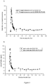
- Two saline solutions containing respectively metal cations (A1) and the sulfur element (B1) are mixed in equal proportions (see table 1 for chemical composition of the solutions).
- the mixture then passes through a tube in which a deposit of metal salts is likely to form).
- the tube is provided with a filter on which the deposit is installed as a priority, making the circulation of the fluid difficult.
- the formation of a deposit is therefore accompanied by an increase in the differential pressure between the ends of the tube.
- the inhibitor is introduced via solution A1 to which it is added in varying concentrations. Subsequent analysis of the filter by SEM and EDX techniques provides precise information on the quantity and nature of the deposits formed.
- the FL1 inhibitor is added to solution A1 in variable amounts so as to obtain the concentrations in Table 2 within the tube.
- these solutions are co-injected with solution B1 (proportions 50/50 by volume) via an alloy tube specific (Ni72Cr16Fr8) of 1 mm outside diameter and 0.8 mm inside diameter.
- Ni72Cr16Fr8 Ni72Cr16Fr8
- the two solutions pass through a filter with a porosity of 7 ⁇ m.
- the solutions are injected at a flow rate of 10 ml / min together.
- a measurement of the differential pressure existing on either side of the filter is carried out over a period of one hour.
- the tests are carried out at a temperature of 125 ° C and at a pressure of 45 bars.
- the results obtained are collated in Table 2 below.
- Two saline solutions containing respectively metal cations (A2) and the sulfur element (B2) are mixed in equal proportions (see table 3 for chemical composition of the solutions).
- the mixture then passes through a tube in which a deposit of metal salts is likely to form).
- the tube is provided with a filter on which the deposit is installed as a priority, making the circulation of the fluid difficult.
- the formation of a deposit is therefore accompanied by an increase in the differential pressure between the ends of the tube.
- the inhibitor is introduced via solution A2 to which it is added in varying concentrations. Subsequent analysis of the filter by SEM and EDX techniques provides precise information on the quantity and nature of the deposits formed.
- the FL1-PC4Si inhibitor is added to solution A2 in variable amounts so as to obtain the concentrations in Table 2 within the tube.
- these solutions are co-injected with solution B2 (proportions 50/50 by volume) via a specific alloy tube (Ni72Cr16Fr8) with 1 mm outside diameter and 0.8 mm inside diameter.
- solution B2 proportions 50/50 by volume
- a specific alloy tube Ni72Cr16Fr8
- the solutions pass through a filter with a porosity of 7 ⁇ m.
- the solutions are injected at a flow rate of 10 ml / min together.
- a measurement of the differential pressure existing on either side of the filter is carried out over a period of one hour.
- the tests are carried out at a temperature of 125 ° C and at a pressure of 45 bars.
- the results obtained are collated in Table 4 below.
- Two saline solutions containing respectively metallic cations (A2) and the sulfur element (B2) are mixed in equal proportions (see table 5 for chemical composition of the solutions).
- the mixture then passes through a tube in which a deposit of metal salts is likely to form).
- the tube is provided with a filter on which the deposit is installed as a priority, making the circulation of the fluid difficult.
- the formation of a deposit is therefore accompanied by an increase in the differential pressure between the ends of the tube.
- the inhibitor is introduced via solution A2 to which it is added in varying concentrations. Subsequent analysis of the filter by SEM and EDX techniques provides precise information on the quantity and nature of the deposits formed.
- the inhibitor FL1-PC4Si (which has undergone thermal aging or not) is added to solution A2 in variable amounts so as to finally obtain the concentrations in Table 6. These solutions are then co-injected with solution B (proportions 50 / 50 by volume) via a specific alloy tube (Ni72Cr16Fr8) with an outside diameter of 1 mm and an inside diameter of 0.8 mm. Once intimately mixed the two solutions pass through a filter with a porosity of 7 ⁇ m. The solutions are injected at a flow rate of 10 ml / min together. A measurement of the differential pressure existing on either side of the filter is carried out over a period of one hour. The tests are carried out at a temperature of 125 ° C and at a pressure of 45 bars.
- a blocking test was set up. It consists in measuring the time necessary for a filter blockage by depositing metal salts to occur.
- C 0 is the initial inhibitor concentration in mg / L.
- V is the volume of the inhibitor solution in L.
- C eq is the concentration of the inhibitor in equilibrium in mg / L and m is the mass of the porous medium.
- the cartridge in question consists of a cylindrical rock core embedded in a PVC tube and linked to it by an epoxy resin.
- the bases are perforated on either side of the cartridge allowing a double syringe pump system to ensure a continuous flow through the system at a variable rate.
- the presence of the inhibitor at the output is detected by complexation of free terbium ion by it. Once chelated, the phosphorescence of the Terbium ions is greatly enhanced.
- the first step is to carry out the circulation of seawater alone at a height of approximately 100 times the pore volume of the rock core through (300mL / h). Once washed in this way, the cartridge is ready to receive the inhibitor.
- a first test was carried out using a solution of TP8106G at 1% by mass as an inhibitor with or without silica nanoparticles without gadolinium (more precisely it is a solution A / 20; see example 16 and 17 for the synthesis of nanoparticles and the preparation of the inhibitor formulation with nanoparticles)
- the inhibitor solutions are injected in diluted form in sea water (solution at 2% by mass): 5 times the pore volume of this solution are passed through the rock (at a flow rate of 500mL / h).
- the injection of seawater alone is then resumed (300mL / h) until it is no longer possible to detect the inhibitor in the samples taken automatically at regular time intervals at the outlet of the core.
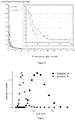
- the results are visible in figure 4 .
- a higher retention is observed for the nanoparticulate formulation of the inhibitory solution (squares) than for the conventional formulation (circles).
- silica nanoparticles without gadolinium is carried out by simple mixture of organosilane precursors: (3-Aminopropyl) triethoxysilane and tetraethyl orthosilicate (APTES and TEOS) in water.
- TEOS 3-Aminopropyl) triethoxysilane and tetraethyl orthosilicate
- TEOS is added with vigorous stirring alone, then after approximately 10 minutes the APTES is also stirring is maintained.
- the proportions of the two reagents can be varied.
- the solution is then kept stirring overnight. No purification step is carried out thereafter.
- the figure 7 gives the signature in dynamic light scattering (DLS) of nanoparticles at the end of synthesis for 50/50 proportions by mass of APTES and TEOS.
- Solution A squares
- Solution B circles
- the average sizes obtained are 720nm and 190nm respectively.
- Example 17 Preparation of TP8106G nano-inhibitor solution with nanoparticles without gadolinium:
- Solutions A and B obtained in Example 16 are diluted by a given dilution factor and left stirring for a period of between 1h and 72h.
- the solutions thus obtained are then mixed in equal proportions with a commercial solution of TP8106G, itself diluted by 2.
- the solutions finally obtained are left under stirring for 24 h then analyzed by DLS.
Description
L'invention concerne une nouvelle formulation avec nanoparticules d'inhibiteurs de dépôts minéraux. Ces solutions d'inhibiteurs sont employées pour empêcher ou du moins ralentir la formation de dépôts de minéraux dans un puits lors de l'extraction de gaz ou de pétrole, en particuliers les dépôts de sulfures, sulfates ou carbonates métalliques.The invention relates to a new formulation with nanoparticles of inhibitors of mineral deposits. These inhibitor solutions are used to prevent or at least slow down the formation of mineral deposits in a well during the extraction of gas or petroleum, in particular the deposits of sulphides, sulphates or metallic carbonates.
L'invention vise également leur procédé d'obtention ainsi que leurs applications.The invention also relates to their process for obtaining as well as their applications.
Lors de l'exploitation de champs pétroliers ou gaziers, la récupération de pétrole peut être améliorée par l'injection d'eau au sein du gisement exploité ceci via un puits d'injection et de manière à pousser le pétrole du gisement hors du sous-sol, par au moins un autre puits appelé puits de production. L'interaction de l'eau injectée avec le réservoir contenant le gaz, le pétrole et des eaux souterraines peut résulter en la formation d'espèces chimiques susceptibles d'entraîner des défauts de fonctionnement des installations. Des dépôts de sulfate de baryum sont tout particulièrement à craindre. D'autres types de dépôts par exemple de carbonate de calcium ou de sulfures de zinc et de plomb, peuvent se former aussi bien en présence d'eau d'injection qu'en son absence. Ces derniers sont notamment susceptibles de se former dans des conditions d'exploitation à haute pression et haute température ou lors de la mise en contact de la saumure injectée pour extraire le pétrole ou le gaz avec le sulfure d'hydrogène ou les ions contenus dans le réservoir. La production d'eau de réservoir ou d'aquifère simultanément avec le pétrole ou le gaz peut entrainer les mêmes phénomènes. Ces dépôts minéraux sont susceptibles d'obstruer les canaux d'écoulement dans la formation, de polluer les canalisations et les équipements de surface et de bloquer les systèmes de pompage et les vannes de sécurité. Plus généralement, des dépôts minéraux ou des phénomènes de corrosion peuvent apparaître dans différentes conditions d'exploitation.During the exploitation of oil or gas fields, oil recovery can be improved by injecting water into the exploited deposit via an injection well and so as to push the oil from the deposit out of the sub- soil, through at least one other well called a production well. The interaction of the injected water with the reservoir containing the gas, oil and groundwater can result in the formation of chemical species which can cause malfunctions of the installations. Barium sulphate deposits are particularly to be feared. Other types of deposits, for example calcium carbonate or zinc and lead sulfides, can form both in the presence of injection water and in its absence. The latter are in particular liable to form under operating conditions at high pressure and high temperature or when the injected brine is brought into contact to extract the oil or gas with hydrogen sulfide or the ions contained in the tank. The production of reservoir or aquifer water simultaneously with oil or gas can cause the same phenomena. These mineral deposits are likely to obstruct the flow channels in the formation, pollute the pipes and surface equipment and block the pumping systems and safety valves. More generally, mineral deposits or corrosion phenomena can appear under different operating conditions.
Une solution couramment employée pour l'élimination de ces dépôts minéraux a consisté à effectuer des lavages acides répétés. Outre le problème de leur courte durée d'action, ces traitements ne sont pas sans risques pour les équipements comme pour les hommes, en particulier dans des conditions de haute pression et haute température.A commonly used solution for the removal of these mineral deposits has consisted in carrying out repeated acid washings. In addition to the problem of their short duration of action, these treatments are not without risks for the equipment as for the men, in particular under conditions of high pressure and high temperature.
Pour remédier à ce problème, il est possible d'inhiber la formation de ces dépôts par injection continue d'inhibiteurs en fond de puits quand des installations sont en place. La technique d'injection dite en « squeeze » constitue une alternative à l'injection continue.To remedy this problem, it is possible to inhibit the formation of these deposits by continuous injection of inhibitors downhole when facilities are in place. The “squeeze” injection technique is an alternative to continuous injection.
Celle-ci consiste en l'injection d'une grande quantité de produit dans le réservoir pétrolier alors que la production est arrêtée. L'inhibiteur de dépôt une fois injecté au sein du réservoir doit s'adsorber sur la roche pour être par la suite relargué progressivement lors de la remise en production, ceci afin d'empêcher la formation des dépôts sur une longue période de temps, pendant la production de l'eau de réservoir.This consists of injecting a large quantity of product into the petroleum tank while production is stopped. The deposit inhibitor, once injected into the reservoir, must adsorb on the rock and then be gradually released during the return to production, this in order to prevent the formation of deposits over a long period of time, during production of reservoir water.
Les inhibiteurs moléculaires de dépôts minéraux classiquement utilisés dans l'art antérieur en injection « squeeze » incluent les phosphonates, les polymères de vinylsulfonate (PVS), les acides polycarboxyliques sulfonatés (SPCA) ainsi que les acides polyphosphinocarboxylique (PPCA) éventuellement sulfonatés (
Il subsiste donc le besoin de disposer d'un composé permettant d'inhiber ou de ralentir la formation de dépôts de minéraux ou de sulfures, qui soit stable à haute température et haute pression et/ou qui puisse être efficace pour une injection en squeeze. Il serait en outre souhaitable que ce composé puisse être libéré de manière prolongée, et qu'il soit simple à produire et/ou peu couteux. Enfin, il serait avantageux que ces composés soit rapidement biodégradables et peu toxiques pour l'environnement.There therefore remains the need for a compound which makes it possible to inhibit or slow down the formation of deposits of minerals or sulphides, which is stable at high temperature and high pressure and / or which can be effective for squeeze injection. It would further be desirable for this compound to be able to be released over a prolonged period, and to be simple to produce and / or inexpensive. Finally, it would be advantageous for these compounds to be rapidly biodegradable and not very toxic for the environment.
Les inventeurs ont démontré que ces besoins pouvaient être satisfaits en utilisant de nouvelles nanoparticules comprenant
- (i) une matrice de polyorganosiloxane (POS); éventuellement en enrobage d'un cœur en oxyde de lanthanide, et
- (ii) au moins un inhibiteur polymérique de dépôts.
- (i) a polyorganosiloxane (POS) matrix; optionally by coating a lanthanide oxide core, and
- (ii) at least one polymeric deposit inhibitor.
La présente invention a pour objet des nanoparticules telles que définies dans la revendication 1.The subject of the present invention is nanoparticles as defined in claim 1.
L'invention a également pour objet un procédé d'obtention de ces nanoparticules, tel que défini dans la revendication 10, et leurs utilisations pour inhiber ou ralentir la formation de dépôts minéraux ou soufrés dans un puits lors de l'extraction de pétrole ou de gaz, telles que définies dans la revendication 13.The invention also relates to a process for obtaining these nanoparticles, as defined in claim 10, and their uses for inhibiting or slowing the formation of mineral or sulfur deposits in a well during the extraction of petroleum or gases, as defined in claim 13.
De façon avantageuse, les inventeurs ont en effet montré que les nanoparticules selon la présente invention, aussi appelées ci-après « Nano-inhibiteurs », ont une efficacité au moins comparable aux inhibiteurs moléculaires conventionnelles, mais présentent une résistance remarquable à la dégradation à haute température. De plus, leur taille inférieure au micron et leur nature hydrophile permet d'envisager une interaction efficace avec la roche pour une utilisation en « squeeze », notamment dans des conditions de haute température et/ou haute pression.Advantageously, the inventors have in fact shown that the nanoparticles according to the present invention, also called hereinafter “Nano-inhibitors”, have an effectiveness at least comparable to conventional molecular inhibitors, but exhibit remarkable resistance to degradation at high temperature. In addition, their size less than a micron and their hydrophilic nature makes it possible to envisage an effective interaction with the rock for use in “squeeze”, in particular in conditions of high temperature and / or high pressure.
Les nanoparticules selon la présente invention, ou « Nano-inhibiteurs » sont caractérisées en ce qu'elles comprennent chacune
- (i) une matrice de polyorganosiloxane (POS); éventuellement en enrobage d'un cœur en oxyde de lanthanide,
- (ii) un enrobage à base essentiellement d'inhibiteurs polymériques de dépôts minéraux ou de dépôts soufrés lors de l'extraction de gaz ou de pétrole,
- les polyacides carboxyliques,
- les polymères d'acide sulfonique,
- les phosphates ou phosphonates,
- les acides polyphosphinocarboxyliques,
- des fonctions amides, et
- (i) a polyorganosiloxane (POS) matrix; optionally by coating a lanthanide oxide core,
- (ii) a coating based essentially on polymeric inhibitors of mineral deposits or of sulfur deposits during gas or petroleum extraction,
- polycarboxylic acids,
- sulfonic acid polymers,
- phosphates or phosphonates,
- polyphosphinocarboxylic acids,
- amide functions, and
Ces Nano-inhibiteurs sont aptes à inhiber ou ralentir la formation de dépôts minéraux lors de l'extraction de gaz ou de pétrole, du fait de la présence d'au moins un inhibiteur polymérique de dépôts en leur sein, associés à la matrice de polyorganosiloxane, de préférence par des liaisons non covalentes. La structure des nanoparticules selon l'invention, ou Nano-inhibiteurs, est ainsi constituée d'une partie centrale ou noyau, essentiellement à base de polyorganosiloxane et, le cas échéant, comprenant un cœur en oxyde de lanthanide, et d'un enrobage du noyau, formé essentiellement d'inhibiteurs polymériques de dépôts, relié au noyau de préférence par des interactions non-covalentes, notamment des interactions électrostatiques.These Nano-inhibitors are capable of inhibiting or slowing the formation of mineral deposits during gas or petroleum extraction, due to the presence of at least one polymeric deposit inhibitor within them, associated with the polyorganosiloxane matrix. , preferably by non-covalent bonds. The structure of the nanoparticles according to the invention, or Nano-inhibitors, thus consists of a central part or core, essentially based on polyorganosiloxane and, if necessary, comprising a lanthanide oxide core, and of a coating of the nucleus, formed essentially of polymeric deposit inhibitors, preferably linked to the nucleus by non-covalent interactions, in particular electrostatic interactions.
Dans un mode de réalisation préféré, la masse des inhibiteurs de dépôts représente plus de 80% de la masse totale de chaque nanoparticule, de préférence plus de 90%, voire plus de 95%, 96%, 97%, 98% et même plus de 99%.In a preferred embodiment, the mass of the deposit inhibitors represents more than 80% of the total mass of each nanoparticle, preferably more than 90%, or even more than 95%, 96%, 97%, 98% and even more 99%.
Le noyau à base de polyorganosiloxane (POS) peut être synthétisé selon les techniques de synthèse classiques connues de l'homme du métier. La voie dite « sol-gel » est par exemple couramment employée pour de telles structures. Dans un mode particulier de réalisation, le noyau est une nanoparticule hybride de type cœur/coquille, avec un cœur d'oxyde de lanthanide autour duquel est généré un enrobage de polyorganosiloxane. Dans un mode de réalisation spécifique, le cœur de nanoparticules à base d'oxydes de lanthanide est entièrement dissout et la nanoparticule ne présente plus de cristaux d'oxydes de lanthanide, comme décrit par exemple dans la demande
Au sens de l'invention, les lanthanides sont les métaux de terres rares choisis parmi la série des éléments de numéros 57 (lanthane) à 71 (lutétium). On ajoutera à cette liste, l'yttrium, qui n'est pas réellement considéré comme un lanthanide mais qui est une terre rare de chimie comparable, rendant cet élément également utilisable dans le cadre de la présente invention. Dans un mode de réalisation préféré, on utilisera l'oxyde de gadolinium. La matrice à base de polyorganosiloxane composant le noyau est formée quant à elle majoritairement de composés comprenant les éléments Si, C, H, O et N, base des silicones. La matrice de polyorganosiloxane peut être avantageusement fonctionnalisée par des groupements -R, de préférence par covalence à base de liaison silanes Si-R en surface et issus de composés hydrophiles choisis parmi les dérivés d'amines, en particulier dans le groupe constitué par: aminopropyl, N-(2-aminoethyl-3-aminopropyl ; Bis(2-hydroxyethyl)-3-Aminopropyl ; N-propyl-N, N, N-trimethylamonium ; N-Propul-N, N, N-tri-n-butyl ammonium ; 11-amino-undecyl, N-(2-aminoethyl)-11amino-undecyl.Within the meaning of the invention, the lanthanides are the rare earth metals chosen from the series of elements with the numbers 57 (lanthanum) to 71 (lutetium). We will add to this list, yttrium, which is not really considered a lanthanide but which is a rare earth of comparable chemistry, making this element also usable in the context of the present invention. In a preferred embodiment, gadolinium oxide will be used. The polyorganosiloxane-based matrix making up the core is mainly composed of compounds comprising the elements Si, C, H, O and N, the basis of the silicones. The polyorganosiloxane matrix can be advantageously functionalized with -R groups, preferably by covalence based on a Si-R silane bond at the surface and derived from hydrophilic compounds chosen from amine derivatives, in particular from the group consisting of: aminopropyl , N- (2-aminoethyl-3-aminopropyl; Bis (2-hydroxyethyl) -3-Aminopropyl; N-propyl-N, N, N-trimethylamonium; N-Propul-N, N, N-tri-n-butyl ammonium; 11-amino-undecyl, N- (2-aminoethyl) -11amino-undecyl.
Dans un mode de réalisation préféré, la matrice de polyorganosiloxane comprend des fonctions à charges positives, et de préférence des fonctions amines libres. Dans un mode préféré de réalisation, la matrice de polyorganosiloxane comprend un rapport mol/mol [groupement amine libre]/ [atome de silice] d'au moins 10% et de préférence d'au moins 30%. Les fonctions amines ou plus généralement, les fonctions à charge positive, présentent dans le noyau de la nanoparticule permettent l'interaction du noyau avec les inhibiteurs polymériques de dépôts, en général de charge négative.In a preferred embodiment, the polyorganosiloxane matrix comprises functions with positive charges, and preferably free amine functions. In a preferred embodiment, the polyorganosiloxane matrix comprises a mol / mol [free amine group] / [silica atom] ratio of at least 10% and preferably at least 30%. The amine functions or more generally, the positively charged functions present in the nucleus of the nanoparticle allow the interaction of the nucleus with the polymeric inhibitors of deposits, generally of negative charge.
Dans un autre mode de réalisation, le noyau à base de polyorganosiloxane est généré directement à partir de noyaux de polysiloxanes, par exemple, issus de 3-Aminopropyl)triethoxysilane (APTES) et d'orthosilicate de tétraétyhle (TEOS) comme décrit en Exemple. En particulier, au moins 10% d'APTES est mis à réagir avec du TEOS pour former le noyau à base de polyorganosiloxane.In another embodiment, the polyorganosiloxane-based core is generated directly from polysiloxane cores, for example, derived from 3-Aminopropyl) triethoxysilane (APTES) and tetraetyhle orthosilicate (TEOS) as described in Example. In particular, at least 10% of APTES is reacted with TEOS to form the core based on polyorganosiloxane.
En général, l'ensemble cœur + matrice de polyorganosiloxane qui forment le noyau des Nano-inhibiteurs n'excède pas un diamètre moyen en volume de 10nm, de préférence le diamètre moyen est inférieur à 5nm pour l'ensemble cœur + matrice de polyorganosiloxane.In general, the core + polyorganosiloxane matrix which form the core of the nano-inhibitors does not exceed an average diameter by volume of 10 nm, preferably the mean diameter is less than 5 nm for the core + polyorganosiloxane matrix.
La distribution de taille des nanoparticules est par exemple mesurée à l'aide d'un granulomètre commercial, tel qu'un granulomètre Malvern Zêta sizer Nano-S basé sur la PCS (Photon Correlation Spectroscopy). Cette distribution est caractérisée par un diamètre moyen et un indice de polydispersité.The size distribution of the nanoparticles is for example measured using a commercial particle size analyzer, such as a Malvern Zeta sizer Nano-S particle size analyzer based on PCS (Photon Correlation Spectroscopy). This distribution is characterized by an average diameter and a polydispersity index.
Au sens de l'invention, par « diamètre moyen », on entend la moyenne harmonique des diamètres des particules. L'indice de polydispersité fait référence à la largeur de la distribution en taille dérivant de l'analyse des cumulants. Ces deux caractéristiques sont décrites dans la norme ISO 13321 :1996.Within the meaning of the invention, by "mean diameter" means the harmonic mean of the diameters of the particles. The polydispersity index refers to the width of the size distribution derived from the cumulants analysis. These two characteristics are described in ISO 13321: 1996.
Dans un autre mode de réalisation, le noyau à base de polyorganosiloxane est constitué essentiellement de polyorganosiloxanes, et le cas échéant d'oxyde de gadolinium. En particulier, dans un mode plus spécifique, le noyau est exempt d'alumines, de zircones, d'aluminates, d'aluminophosphates et/ou d'oxydes métalliques.In another embodiment, the polyorganosiloxane-based core consists essentially of polyorganosiloxanes, and optionally gadolinium oxide. In particular, in a more specific mode, the nucleus is free of aluminas, zirconia, aluminates, aluminophosphates and / or metal oxides.
Les Nano-inhibiteurs selon l'invention sont caractérisées en ce qu'ils comprennent un enrobage à base essentiellement d'inhibiteurs polymériques de dépôts minéraux ou de dépôts soufrés. Ces inhibiteurs présentent de préférence des charges négatives qui permettent une interaction stable par des liaisons non covalentes au noyau de la nanoparticule comprenant la matrice de polyorganosiloxanes, qui elle, est chargée positivement dans les conditions normales d'utilisation.The nano-inhibitors according to the invention are characterized in that they comprise a coating based essentially on polymeric inhibitors of mineral deposits or of sulfur deposits. These inhibitors preferably have negative charges which allow a stable interaction via non-covalent bonds to the nucleus of the nanoparticle comprising the polyorganosiloxane matrix, which itself is positively charged under normal conditions of use.
Par "inhibiteur de dépôts minéraux", on entend un composé capable d'empêcher ou de ralentir la formation (c'est-à-dire la nucléation et/ou la croissance) de cristaux de sels minéraux choisis notamment parmi : le carbonate de calcium, le sulfate de calcium, le sulfate de baryum, le sulfate de strontium, les sulfures de zinc, de plomb et de fer et leurs mélanges.By "mineral deposit inhibitor" is meant a compound capable of preventing or slowing down the formation (that is to say nucleation and / or growth) of crystals of mineral salts chosen in particular from: calcium carbonate , calcium sulphate, barium sulphate, strontium sulphate, zinc, lead and iron sulphides and their mixtures.
Les inhibiteurs de dépôts minéraux utilisables selon l'invention sont choisis parmi des polymères ou copolymères contenant au moins une des fonctions suivantes :
- les polyacides carboxyliques,
- les polymères d'acide sulfonique,
- les phosphates ou phosphonates,
- les acides polyphosphinocarboxyliques,
- des fonctions amides.
- polycarboxylic acids,
- sulfonic acid polymers,
- phosphates or phosphonates,
- polyphosphinocarboxylic acids,
- amide functions.
Ils sont encore plus spécifiquement choisis parmi :
- les polyphosphates, tels que le tripolyphosphate de sodium (STPP), l'hexamétaphosphate de sodium (SHMP),
- les organophosphonates, tels que l'acide amino tri(méthylène phosphonique) ou AMP, l'acide 1-hydroxyéthylidène-1,1-diphosphonique ou HEDP, l'acide éthylènediamine tétra(méthylène phosphonique) ou EDTMP, l'acide hexaméthylènediamine tétra(méthylène phosphonique) ou HMTMP, l'acide diéthylènetriamine penta(méthylène phosphonique) ou DETMP, l'acide hydroxyéthylamino-di(méthylènephosphonique) (HEMPA),
- les polyacides carboxyliques tels que l'acide 2-phosphonobutane 1,2,4-tricarboxylique ou PBTC, le poly(acide acrylique) ou PAA, le poly(acide méthacrylique) ou PMAA, le poly(acide maléique) ou PMA,
- les polymères à fonction acide sulfonique, tels que les copolymères d'acide styrène sulfonique et d'acide (poly)carboxylique, en particulier les copolymères d'acide styrène sulfonique et d'acide maléique, les copolymères d'acide styrène sulfonique et de (poly)amido-amine, les homo- et copolymères de vinylsulfonate, en particulier les copolymères de vinylsulfonate, de styrène et d'anhydride maléique, les alkyldiphényléther sulfonates et les copolymères d'acide acrylamidométhylpropane sulfonique (AMPS), d'acide maléique et d'acide acrylique,
- l'acide polyphosphinocarboxylique (PPCA) éventuellement sulfonaté.
- polyphosphates, such as sodium tripolyphosphate (STPP), sodium hexametaphosphate (SHMP),
- organophosphonates, such as amino tri acid (methylene phosphonic) or AMP, 1-hydroxyethylidene-1,1-diphosphonic acid or HEDP, ethylenediamine acid tetra (methylene phosphonic) or EDTMP, hexamethylenediamine acid tetra (methylene phosphonic) or HMTMP, diethylenetriamine penta acid (methylene phosphonic) or DETMP, hydroxyethylamino-di (methylenephosphonic acid),
- polycarboxylic acids such as 2-phosphonobutane 1,2,4-tricarboxylic acid or PBTC, poly (acrylic acid) or PAA, poly (methacrylic acid) or PMAA, poly (maleic acid) or PMA,
- polymers with a sulfonic acid function, such as copolymers of styrene sulfonic acid and (poly) carboxylic acid, in particular copolymers of styrene sulfonic acid and maleic acid, copolymers of styrene sulfonic acid and ( poly) amido-amine, vinyl sulfonate homo- and copolymers, in particular copolymers of vinyl sulfonate, styrene and maleic anhydride, alkyldiphenyl ether sulfonates and copolymers of acrylamidomethylpropane sulfonic acid (AMPS), maleic acid and d 'acrylic acid,
- optionally sulfonated polyphosphinocarboxylic acid (PPCA).
Par "inhibiteur de dépôts soufrés", on entend un composé capable de réduire ou ralentir la formation de dépôt de sulfure.By "sulfur deposit inhibitor" is meant a compound capable of reducing or slowing the formation of sulfide deposits.
Un inhibiteur polymérique de dépôt soufrés est un copolymère constitué uniquement d'unités comprenant (et de préférence constituées par) un motif acide styrène sulfonique éventuellement neutralisé et d'unités renfermant (et de préférence constituées par) un motif acide (poly)carboxylique éventuellement neutralisé ou au moins un motif (poly)amido-amine. Par "motif acide (poly)carboxylique", on entend un motif portant une ou plusieurs fonctions acides carboxyliques. Ce motif est avantageusement obtenu à partir d'un monomère insaturé portant au moins une, et de préférence deux, fonctions acides carboxyliques, choisi par exemple parmi l'acide maléique, l'acide fumarique, l'acide itaconique, l'acide citraconique, l'anhydride cis-1,2,3,6-tétrahydro-phthalique, l'acide maléique étant préféré. Ces motifs acides carboxyliques peuvent être neutralisés à l'aide de sels de sodium, de potassium ou d'ammonium, de préférence de sels de sodium. Le motif (poly)amido-amine peut être obtenu par réaction de tout ou partie des fonctions acides carboxyliques avec un composé, de préférence un polymère, portant au moins deux fonctions amines primaires ou secondaires, qui peut être choisi notamment parmi : les polyamines telles que la DETA (diéthylène triamine), la TETA (triéthylène tétramine), la TEPA (tétraéthylène pentamine), la dihexylène triamine et la polyéthylèneimine (PEI) ; les polymères siliconés, en particulier les polydiméthylsiloxanes, fonctionnalisés par des groupements amines ; les chitosans ; les polypeptides et protéines, de préférence la DETA et la PEI.A sulfur-containing polymeric inhibitor is a copolymer consisting solely of units comprising (and preferably consisting of) an optionally neutralized styrene sulfonic acid unit and of units containing (and preferably consisting of) an optionally neutralized (poly) carboxylic acid unit or at least one (poly) amido-amine unit. By "(poly) carboxylic acid unit" is meant a unit carrying one or more carboxylic acid functions. This unit is advantageously obtained from an unsaturated monomer carrying at least one, and preferably two, carboxylic acid functions, chosen for example from maleic acid, fumaric acid, itaconic acid, citraconic acid, cis-1,2,3,6-tetrahydro-phthalic anhydride, maleic acid being preferred. These carboxylic acid units can be neutralized using sodium, potassium or ammonium salts, preferably sodium salts. The (poly) amido-amine unit can be obtained by reaction of all or part of the carboxylic acid functions with a compound, preferably a polymer, carrying at least two primary or secondary amine functions, which can be chosen in particular from: polyamines such DETA (diethylene triamine), TETA (triethylene tetramine), TEPA (tetraethylene pentamine), dihexylene triamine and polyethyleneimine (PEI); silicone polymers, in in particular polydimethylsiloxanes, functionalized with amine groups; chitosans; polypeptides and proteins, preferably DETA and PEI.
Dans un mode de réalisation plus spécifique, le pourcentage molaire, dans le copolymère selon l'invention, d'unités renfermant un motif acide styrène sulfonique éventuellement neutralisé soit compris entre 10 et 90%, de préférence entre 25 et 75% et, mieux, entre 50 et 70%.Ce copolymère peut renfermer au moins une autre unité chimiquement distincte de celles précitées et qui peut par exemple représenter au plus 20% mol et de préférence au plus 10% mol, par rapport au nombre de moles totales d'unités monomères dans ledit copolymère. Cette autre unité peut être choisie notamment parmi les (méth)acrylamides, les esters d'acide (méth)acrylique, l'acétate de vinyle, le styrène et le vinyltoluène.In a more specific embodiment, the molar percentage, in the copolymer according to the invention, of units containing an optionally neutralized styrene sulfonic acid unit is between 10 and 90%, preferably between 25 and 75% and, better still, between 50 and 70%. This copolymer may contain at least one other chemically distinct unit from those mentioned above and which may for example represent at most 20% mol and preferably at most 10% mol, relative to the number of total moles of units monomers in said copolymer. This other unit can be chosen in particular from (meth) acrylamides, (meth) acrylic acid esters, vinyl acetate, styrene and vinyltoluene.
Dans un autre mode de réalisation spécifique, l'inhibiteur polymérique utilisé dans les nanoparticules selon l'invention répond avantageusement à la formule suivante :

Selon une forme d'exécution plus spécifique de l'invention, tout ou partie des fonctions acides carboxyliques du copolymère sont substituées par des fonctions amido-amines résultant, comme indiqué précédemment, de la réaction de ces fonctions acides carboxyliques avec au moins deux fonctions amines primaires ou secondaires portées par un composé qui est mis à réagir avec les unités renfermant au moins un motif acide (poly)carboxylique du copolymère. Il a en effet été observé que ces copolymères présentaient des propriétés améliorées d'inhibition de la formation de dépôts sulfures. On pense que ces copolymères permettent d'obtenir un effet inhibiteur prolongé, par hydrolyse progressive des fonctions amides, mais également une action plus efficace, dans la mesure où le doublet libre de l'atome d'azote des fonctions amines n'ayant pas participé aux liaisons amides est utile pour complexer les sites de surface des particules de sulfure de zinc et de plomb. Ces copolymères à fonctions amido-amines limitent également les interactions entre les unités acides (poly)carboxyliques et des dépôts de sulfate de baryum ou de carbonate de calcium, par exemple, ce qui peut permettre d'éviter que le copolymère réagisse exclusivement avec ces dépôts qui ont tendance, dans certaines conditions, à se former avant les dépôts de sulfures.According to a more specific embodiment of the invention, all or part of the carboxylic acid functions of the copolymer are substituted by amido-amine functions resulting, as indicated above, from the reaction of these carboxylic acid functions with at least two amine functions primary or secondary carried by a compound which is reacted with the units containing at least one (poly) carboxylic acid unit of the copolymer. It has in fact been observed that these copolymers have improved properties for inhibiting the formation of sulphide deposits. It is believed that these copolymers make it possible to obtain a prolonged inhibitory effect, by progressive hydrolysis of the amide functions, but also a more effective action, insofar as the free doublet of the nitrogen atom of the amine functions has not participated amide bonding is useful for complexing the surface sites of zinc and lead sulfide particles. These copolymers with amido-amine functions also limit the interactions between the (poly) carboxylic acid units and deposits of barium sulphate or calcium carbonate, for example, which can make it possible to prevent the copolymer from reacting exclusively with these deposits which tend, under certain conditions, to form before the sulphide deposits.
Ce copolymère spécifique peut être obtenu suivant des procédés classiques de polymérisation radicalaire en voie aqueuse ou hydro-alcoolique et à pH acide. Il est également disponible dans le commerce auprès des sociétés ALDRICH ou AKZO NOBEL.This specific copolymer can be obtained according to conventional radical polymerization processes in aqueous or hydroalcoholic way and at acid pH. It is also commercially available from ALDRICH or AKZO NOBEL.
Dans un autre mode de réalisation spécifique, les Nanoinhibiteurs sont caractérisés en ce qu'ils comprennent un inhibiteur polymérique de dépôts choisi parmi les copolymères d'acide styrène sulfonique et d'acide (poly)carboxylique, en particulier les copolymères d'acide styrène sulfonique et d'acide maléique, et les copolymères d'acide styrène sulfonique et de (poly)amidoamine.In another specific embodiment, the Nanoinhibitors are characterized in that they comprise a polymeric deposit inhibitor chosen from copolymers of styrene sulfonic acid and (poly) carboxylic acid, in particular copolymers of styrene sulfonic acid and maleic acid, and copolymers of styrene sulfonic acid and (poly) amidoamine.
Dans un mode de réalisation spécifique, les Nano-inhibiteurs sont caractérisés en ce qu'ils comprennent un inhibiteur polymérique de dépôts d'une masse molaire d'au moins 10 kDa, de préférence supérieure à 20 kDa.In a specific embodiment, the Nano-inhibitors are characterized in that they comprise a polymeric inhibitor of deposits with a molar mass of at least 10 kDa, preferably greater than 20 kDa.
Typiquement, le diamètre moyen inférieur des Nano-inhibiteurs peut aller jusqu'à 2µm, par exemple compris entre 20 et 500nm, mais de préférence entre 20 et 200nm.Typically, the lower average diameter of the nano-inhibitors can range up to 2 μm, for example between 20 and 500 nm, but preferably between 20 and 200 nm.
Outre les inhibiteurs polymériques de dépôt comme décrits ci-dessus, les Nanoinhibiteurs peuvent comprendre d'autres inhibiteurs de dépôts, et notamment des phosphonates.In addition to the polymeric deposition inhibitors as described above, the Nanoinhibitors can comprise other deposition inhibitors, and in particular phosphonates.
L'invention concerne aussi un procédé d'obtention des Nano-inhibiteurs tels que décrits plus haut. Ce procédé est caractérisé en ce qu'il comprend les étapes suivantes :
- a. éventuellement synthèse d'un cœur à base d'oxyde de lanthanide, par exemple un cœur d'oxyde de gadolinium,
- b. enrobage des cœurs de l'étape (a) par du polyorganosiloxane (POS) ou préparation d'une nanoparticule de polyorganosiloxane, consistant essentiellement à mettre en œuvre une technique sol/gel d'hydrolyse-condensation d'espèces siliciques et d'alcoxysilanes, en présence d'une base ou d'un acide ;
- c. surenrobage des nanoparticules obtenues à l'étape (b) consistant essentiellement à mettre en présence ces cœurs enrobés ou nanoparticules de polyorganosiloxane de l'étape (b) avec une solution d'inhibiteurs polymériques de dépôts en présence de préférence d'un solvant aqueux ou alcoolique, par exemple les polyéthers, notamment le polyéthylène glycol;
- d. éventuellement purification des nanoparticules, de préférence par filtration tangentielle, dialyse et/ou par précipitation/ lavage ;
- e. éventuellement dissolution des cœurs d'oxydes de lanthanides des nanoparticules de l'étape (b) ou surenrobées de l'étape (c) consistant essentiellement à les mettre en présence d'un agent modificateur du pH et/ou d'un chélatant apte à complexer tout ou partie des cations lanthanides, de sorte que le diamètre des nanoparticules sans le surenrobage est réduit à une valeur comprise entre 1 et 20 nm, de préférence entre 1 et 10 nm ;
- f. les étapes (c), (d), et (e) pouvant être réalisées dans un ordre différent ou en même temps.
- at. optionally synthesis of a lanthanide oxide-based heart, for example a gadolinium oxide heart,
- b. coating of the cores of step (a) with polyorganosiloxane (POS) or preparation of a polyorganosiloxane nanoparticle, essentially consisting in implementing a sol / gel technique of hydrolysis-condensation of silicic species and of alkoxysilanes, in the presence of a base or an acid;
- vs. overcoating of the nanoparticles obtained in step (b) consisting essentially of bringing these coated cores or nanoparticles of polyorganosiloxane from step (b) into contact with a solution of polymeric deposit inhibitors in the presence preferably of an aqueous solvent or alcoholic, for example polyethers, especially polyethylene glycol;
- d. optionally purification of the nanoparticles, preferably by tangential filtration, dialysis and / or by precipitation / washing;
- e. optionally dissolution of the lanthanide oxide cores of the nanoparticles of step (b) or overcoated of step (c) consisting essentially of putting them in the presence of a pH modifying agent and / or a chelating agent capable of complexing all or part of the lanthanide cations, so that the diameter of the nanoparticles without the overcoating is reduced to a value of between 1 and 20 nm, preferably between 1 and 10 nm;
- f. steps (c), (d), and (e) can be carried out in a different order or at the same time.
Dans un mode de réalisation spécifique, les étapes (a) et (b) consistent plus précisément à former une nanoparticule de type cœur-coquille avec un cœur d'oxyde de lanthanide (par exemple par voie polyol modifiée) et une coquille de polysiloxane (par exemple par voie sol/gel), cet objet a par exemple une taille inférieure à 10nm (voire inférieure à 5nm). Un cœur d'oxyde de lanthanide de taille inférieure à 10nm peut être élaboré comme décrit en exemple ou par un des procédés décrits dans les publications suivantes :
A l'étape c), les nanoparticules obtenues à l'étape b) sont mises en présence d'une quantité suffisante d'une solution d'inhibiteurs polymériques de dépôts dans des conditions aptes à permettre l'enrobage (ou surenrobage) des nanoparticules avec les inhibiteurs polymériques de dépôts comme décrit en exemple. Un ajout à vitesse relativement lente et bonne agitation est conseillé à ce niveau.In step c), the nanoparticles obtained in step b) are placed in the presence of a sufficient quantity of a solution of polymeric inhibitors of deposits under conditions suitable for allowing the coating (or overcoating) of the nanoparticles with polymeric deposit inhibitors as described in the example. Addition at relatively slow speed and good agitation is recommended at this level.
L'étape d), optionnelle, consiste à séparer les Nano-inhibiteurs des résidus de synthèse par exemple par une méthode de dialyse ou de filtration tangentielle, sur une membrane comportant des pores de taille adaptée.Step d), optional, consists in separating the Nano-inhibitors from the synthesis residues, for example by a dialysis or tangential filtration method, on a membrane comprising pores of suitable size.
L'étape e), également optionnelle, permet d'obtenir des nanoparticules pour lesquelles le cœur à base d'oxyde de lanthanide est détruit par dissolution (par exemple en modifiant le pH ou en apportant des molécules complexantes dans la solution, comme décrit dans la demande
L'invention a également pour objet
- une suspension de Nano-inhibiteurs tels que décrit plus haut,
- une suspension de Nano-inhibiteurs tels qu'obtenus par le procédé décrit ci-dessus,
- un liquide d'injection pour inhiber ou ralentir la formation de dépôts lors de l'exploitation de gaz ou de pétrole, comprenant des Nano-inhibiteurs tels que définis ci-dessus et/ou, des Nano-inhibiteurs tels qu'obtenus par le procédé décrit ci-dessus, et/ou la suspension de Nano-inhibiteurs susvisée.
- a suspension of Nano-inhibitors as described above,
- a suspension of Nano-inhibitors as obtained by the method described above,
- an injection liquid for inhibiting or slowing down the formation of deposits during the exploitation of gas or petroleum, comprising Nano-inhibitors as defined above and / or, Nano-inhibitors as obtained by the process described above, and / or the suspension of Nano-inhibitors mentioned above.
Les Nano-inhibiteurs selon l'invention ou leurs produits dérivés sont utiles pour inhiber ou ralentir la formation de dépôts soufrés et/ou de minéraux lors de l'extraction de gaz ou de pétrole.The nano-inhibitors according to the invention or their derivative products are useful for inhibiting or slowing the formation of sulfur deposits and / or minerals during the extraction of gas or petroleum.
Du fait de leur bonne tenue thermique, les Nano-inhibiteurs ou leurs produits dérivés peuvent être utilisés en particulier dans des puits pétroliers fonctionnant à haute pression, c'est-à-dire à plus de 10 MPa, par exemple de 20 à 150 MPa, et à haute température, c'est-à-dire de 150 à 250°C, par exemple de 200 à 230°C.Due to their good thermal resistance, Nano-inhibitors or their derivative products can be used in particular in oil wells operating at high pressure, that is to say at more than 10 MPa, for example from 20 to 150 MPa , and at high temperature, that is to say from 150 to 250 ° C., for example from 200 to 230 ° C.
Ils sont également particulièrement appropriés pour une utilisation sous la forme d'une injection desdites nanoparticules en squeeze.They are also particularly suitable for use in the form of an injection of said nanoparticles in a squeeze.
Dans un mode de réalisation, l'invention vise une méthode pour inhiber ou ralentir la formation de dépôts minéraux ou de dépôts soufrés, lors de l'extraction de gaz ou de pétrole, ladite méthode comprenant l'injection, dans un puits de forage, une formation souterraine, ou un puits de pétrole ou de gaz, d'un fluide contenant lesdits Nano-inhibiteurs.In one embodiment, the invention relates to a method for inhibiting or slowing the formation of mineral deposits or sulfur deposits, during the extraction of gas or oil, said method comprising the injection, into a wellbore, an underground formation, or an oil or gas well, of a fluid containing said nano-inhibitors.
Les Nano-inhibiteurs peuvent être injectés dans le puits sous forme d'additif dans un fluide d'injection. Ce fluide peut renfermer de 5 à 100.000 ppm du Nano-inhibiteur décrit précédemment Pour des injections en continue, il est conseillé de choisir des teneurs de l'ordre de 10 à 1000 ppm, pour des injections périodiques, en particulier de type squeeze, il est conseillé d'utiliser des concentrations supérieurs à 1000 ppm.Nano-inhibitors can be injected into the well as an additive in an injection fluid. This fluid can contain from 5 to 100,000 ppm of the nano-inhibitor described above. For continuous injections, it is advisable to choose contents of the order of 10 to 1000 ppm, for periodic injections, in particular of the squeeze type, it it is advisable to use concentrations above 1000 ppm.
En variante, les Nano-inhibiteurs décrits précédemment peuvent être injectés dans le puits en "squeeze", c'est-à-dire suivant un procédé consistant à rincer le puits à l'eau de mer, puis à injecter dans le puits un fluide contenant ce Nano-inhibiteur et à introduire à nouveau de l'eau de mer dans le puits pour disperser le polymère dans le réservoir et lui permettre de s'adsorber sur les formations rocheuses souterraines. Lors de ce traitement, les opérations d'extraction de pétrole sont interrompues et, lorsqu'elles seront reprises, l'inhibiteur polymérique sera libéré progressivement des formations rocheuses pour empêcher ou ralentir la formation des dépôts de sulfures. Dans cette variante, le fluide injecté peut renfermer de l'ordre de 10% en poids des Nano-inhibiteurs décrits ci-dessus.As a variant, the nano-inhibitors described above can be injected into the well in a "squeeze", that is to say according to a process consisting in rinsing the well with sea water, then in injecting into the well a fluid containing this Nano-inhibitor and again introducing seawater into the well to disperse the polymer in the reservoir and allow it to adsorb on underground rock formations. During this treatment, the oil extraction operations are interrupted and, when they are resumed, the polymeric inhibitor will be gradually released from the rock formations to prevent or slow the formation of sulphide deposits. In this variant, the injected fluid can contain on the order of 10% by weight of the nano-inhibitors described above.
Dans tous les cas, le fluide véhiculant les Nano-inhibiteurs peuvent en outre contenir d'autres additifs tels que des inhibiteurs de corrosion, des inhibiteurs de paraffines, des agents tensioactifs ou des agents démulsionnants, des agents dispersants, notamment des dispersants d'asphaltène, des agents moussants ou des agents anti-mousse, des agents biocides, des capteurs d'oxygène, des agents chélatants tels que l'EDTA et le DTPA, et leurs mélanges.In all cases, the fluid carrying the Nano-inhibitors may also contain other additives such as corrosion inhibitors, paraffin inhibitors, surfactants or demulsifying agents, dispersing agents, in particular asphaltene dispersants , foaming agents or anti-foaming agents, biocidal agents, oxygen scavengers, chelating agents such as EDTA and DTPA, and mixtures thereof.
La présente invention sera mieux comprise à la lumière des exemples non limitatifs suivants, qui sont donnés à titre purement illustratif et n'ont pas pour but de limiter la portée de cette invention qui est définie par les revendications annexées.The present invention will be better understood in the light of the following nonlimiting examples, which are given purely by way of illustration and are not intended to limit the scope of this invention which is defined by the appended claims.
-
Figure 1 : Lafigure 1 est un schéma représentant le dispositif Blocking-test.Figure 1 : Thefigure 1 is a diagram representing the Blocking-test device. -
Figure 2 : Lafigure 2 est un graphe représentant l'adsorption statique sur un échantillon de sable en fonction de la concentration initiale d'inhibiteur.Figure 2 : Thefigure 2 is a graph representing the static adsorption on a sample of sand as a function of the initial concentration of inhibitor. -
Figure 3 : Lafigure 3 est un graphe représentant (A) l'intensité de phosphorescence et (B) la concentration, obtenue avec l'inhibiteur polymérique seul (carré) ou sous la forme de nanoinhibiteurs (rond) en fonction du volume injecté.Figure 3 : Thefigure 3 is a graph representing (A) the phosphorescence intensity and (B) the concentration, obtained with the polymeric inhibitor alone (square) or in the form of nanoinhibitors (round) as a function of the volume injected. -
Figure 4 : Lafigure 4 est un graphe représentant l'intensité de phosphorescence normalisée avec une formulation d'inhibiteur comportant des nanoparticules sans gadolinium (courbe du haut) et sans nanoparticules (courbe du bas) en sortie du dispositif de perméation simple.Figure 4 : Thefigure 4 is a graph representing the normalized phosphorescence intensity with an inhibitor formulation comprising nanoparticles without gadolinium (top curve) and without nanoparticles (bottom curve) at the output of the simple permeation device. -
Figure 5 : Lafigure 5 est un schéma représentant le principe des tests de perméation.Figure 5 : Thefigure 5 is a diagram representing the principle of permeation tests. -
Figure 6 : Lafigure 6 est un graphe représentant la quantité d'inhibiteur mesurée en sortie du dispositif de perméation en fonction du volume injecté.Figure 6 : Thefigure 6 is a graph representing the quantity of inhibitor measured at the output of the permeation device as a function of the volume injected. -
Figure 7 : Lafigure 7 est un graphe représentant l'analyse par DLS de la taille des nanoparticules de silice sans gadolinium.Figure 7 : Thefigure 7 is a graph representing the DLS analysis of the size of silica nanoparticles without gadolinium.
Un colloïde de Gd2O3 est préparé dans un réacteur de 10 L thermostaté et équipé d'un agitateur mécanique par dissolution de 167,3 g de chlorure de gadolinium hexahydraté dans 3 L de diéthylène glycol. Le mélange est alors chauffé à 140 °C et agité à environ 300 rpm pendant 2 à 3 heures, jusqu'à dissolution complète des cristaux.A colloid of Gd 2 O 3 is prepared in a thermostatic 10 L reactor equipped with a mechanical stirrer by dissolving 167.3 g of gadolinium chloride hexahydrate in 3 L of diethylene glycol. The mixture is then heated to 140 ° C. and stirred at approximately 300 rpm for 2 to 3 hours, until the crystals have completely dissolved.
Une fois que tous les cristaux de chlorure de gadolinium sont dissous, est ajouté goutte à goutte 44,55 mL de solution NaOH 10M. Le mélange est laissé sous agitation à environ 250 rpm à 180°C pendant 5 heures. Ce même mélange est ensuite laissé à refroidir à température ambiante (20 à 30 °C) sous une agitation à 200 rpm pendant au moins 12 heures.Once all of the gadolinium chloride crystals have dissolved, 44.55 mL of 10M NaOH solution is added dropwise. The mixture is left under stirring at around 250 rpm at 180 ° C for 5 hours. This same mixture is then left to cool to room temperature (20 to 30 ° C) with stirring at 200 rpm for at least 12 hours.
La mesure de la taille moyenne des cœurs est réalisée par granulométrie laser directement dans le DEG sans dilution. Le diamètre moyen en volume est de 1,5 ± 0,5 nm avec moins de 5% de particules au-delà de 5 nm.The measurement of the average size of the cores is carried out by laser granulometry directly in the DEG without dilution. The volume average diameter is 1.5 ± 0.5 nm with less than 5% of particles beyond 5 nm.
Autour de ces particules, une couche de polysiloxane fonctionnalisée est synthétisée par voie sol-gel. Pour ce fait, deux solutions S1 et S2 sont préparées de la façon suivante :
- Pour la solution S1, un mélange homogénéisé d'APTES et de TEOS est préparé sous atmosphère inerte de la façon suivante : dans une bouteille de 2 L, mélanger 1,6 L de DEG, 51,42 mL de TEOS et 80,61 mL d'APTES mesurés à l'aide d'éprouvettes graduées de volume adapté.
- Quant à la solution S2, mélanger 190 mL de DEG; 43,1 mL d'eau ultra pure et 6,94 mL de triéthylamine (TEA) dans une bouteille de 250 mL. Le volume de DEG est mesuré avec une éprouvette graduée de volume adapté et les volumes de TEA et d'eau ultra pure sont prélevés grâce à une pipette Eppendorf de volume adapté. Homogénéiser la solution.
- For solution S 1 , a homogenized mixture of APTES and TEOS is prepared under an inert atmosphere as follows: in a 2 L bottle, mix 1.6 L of DEG, 51.42 mL of TEOS and 80.61 mL of APTES measured using graduated cylinders of suitable volume.
- As for solution S 2 , mix 190 mL of DEG; 43.1 mL of ultra pure water and 6.94 mL of triethylamine (TEA) in a 250 mL bottle. The volume of DEG is measured with a graduated cylinder of suitable volume and the volumes of TEA and ultra pure water are removed using an Eppendorf pipette of suitable volume. Homogenize the solution.
Le colloïde est ensuite chauffé à 40 °C sous agitation à 250 rpm. A 40°C, la totalité de la solution S1 est ajoutée soit (1732 mL), ceci à l'aide d'une pompe péristaltique sur une durée de 96 h. Cela correspond à un débit de 300 µL/min. Une heure après le début de l'ajout de la solution S1 184,3 mL de S2 est ajouté à l'aide d'une pompe péristaltique sur une durée de 96 h. Cela correspond à un débit de 32 µL/min.The colloid is then heated to 40 ° C with stirring at 250 rpm. At 40 ° C, all of the solution S 1 is added, ie (1732 mL), this using a peristaltic pump over a period of 96 h. This corresponds to a flow rate of 300 µL / min. One hour after the start of the addition of the S 1 solution, 184.3 mL of S 2 is added using a peristaltic pump over a period of 96 h. This corresponds to a flow rate of 32 µL / min.
Une fois les deux solutions ajoutées, la solution globale formée est maintenue sous agitation à environ 150 rpm à 40°C pendant 72 h.Once the two solutions have been added, the overall solution formed is kept stirring at approximately 150 rpm at 40 ° C for 72 h.
La solution est ramenée à température ambiante (10 à 30°C) et laissée à reposer durant au minimum 12h.The solution is brought to room temperature (10 to 30 ° C) and left to stand for at least 12 hours.
A la fin de ces opérations, La mesure de la taille moyenne des particules est réalisée par granulométrie laser directement dans le DEG, sans dilution. Le diamètre moyen en volume est de 3,0 ± 1,0 nm avec moins de 5% de particules au-delà de 8 nm.At the end of these operations, the measurement of the average particle size is carried out by laser granulometry directly in the DEG, without dilution. The volume average diameter is 3.0 ± 1.0 nm with less than 5% of particles beyond 8 nm.
Le polymère Fl1, acheté à Sigma Aldrich, (CAS : 68037-40-1 ; [CH2CH(C6H4SO3R)]x[CH(CO2R)CH(CO2R)]y, R=H ou Na), possède une masse molaire de l'ordre de 20 kDa. Le polymère présente un ratio de trois fonctions acide styrène sulfonique pour une fonction acide maléique.The polymer Fl1, purchased from Sigma Aldrich, (CAS: 68037-40-1; [CH2CH (C6H4SO3R)] x [CH (CO2R) CH (CO2R)] y , R = H or Na), has a molar mass of l '' order of 20 kDa. The polymer has a ratio of three styrene sulfonic acid functions to one maleic acid function.
Cent grammes de Fl1 sont pesés dans un flacon de 1 L. 1 L d'eau ultra pure est ensuite ajouté et une agitation est maintenue jusqu'à dissolution totale.One hundred grams of Fl1 are weighed in a 1 L bottle. 1 L of ultra pure water is then added and stirring is maintained until complete dissolution.
Dans un flacon de 100 mL est mis à réagir 50 mL de la solution de Fl1, obtenue selon le protocole de l'exemple 2, avec 2,5 mL de la solution de PC4Si, obtenu selon l'exemple 1, et 47,5 mL de diéthylène glycol. Le tout est maintenu sous agitation laisser pendant 24h.In a 100 ml flask is reacted 50 ml of the Fl1 solution, obtained according to the protocol of example 2, with 2.5 ml of the PC4Si solution, obtained according to example 1, and 47.5 mL of diethylene glycol. The whole is kept under stirring leave for 24 hours.
La mesure de la taille moyenne des particules est ensuite réalisée par granulométrie laser après dilution dix fois dans l'eau ultra pure. Le diamètre moyen en volume est de 55 nm ± 5,0 nm.The measurement of the average particle size is then carried out by laser granulometry after dilution ten times in ultra pure water. The volume average diameter is 55 nm ± 5.0 nm.
Dans six flacons de 100 mL sont mis à réagir 50 mL de la solution de Fl1, obtenus selon l'exemple 2, avec respectivement, 0 mL, 0,1 mL, 0,5 mL, 1 mL, 5 mL et 10 mL de la solution de PC4Si obtenus selon l'exemple 1 et respectivement, 50 mL, 49,9 mL, 49,5 mL, 49 mL, 45 mL et 40 mL de diéthylène glycol et laisser agiter 24h.In six 100 ml flasks are reacted 50 ml of the Fl1 solution, obtained according to Example 2, with respectively, 0 ml, 0.1 ml, 0.5 ml, 1 ml, 5 ml and 10 ml of the PC4Si solution obtained according to Example 1 and respectively, 50 mL, 49.9 mL, 49.5 mL, 49 mL, 45 mL and 40 mL of diethylene glycol and leave to stir for 24 hours.
La mesure des tailles moyenne des particules est réalisée par granulométrie laser après dilution par un facteur dix dans l'eau ultra pure. Les diamètres moyen en volume sont respectivement de 60 nm ± 10 nm, 65 nm ± 10 nm, 65 nm ± 10 nm, 15 nm ± 1 nm, 10 nm ± 1 nm et 1 nm ± 0,05 nm.The average particle size is measured by laser granulometry after dilution by a factor of ten in ultra pure water. The volume average diameters are respectively 60 nm ± 10 nm, 65 nm ± 10 nm, 65 nm ± 10 nm, 15 nm ± 1 nm, 10 nm ± 1 nm and 1 nm ± 0.05 nm.
Le polymère, nommé IDOS150 ou BelasolS50, est fourni par R.E.P. Recherche Exploitation Produits (CAS : 110152-61-9).The polymer, named IDOS150 or BelasolS50, is supplied by R.E.P. Product Exploitation Research (CAS: 110152-61-9).
100 grammes d'IDOS150 sont pesés dans une fiole jaugée de 1 L. Le volume est ensuite ajusté à 1 L avec de l'eau ultra pure et la solution homogénéisée.100 grams of IDOS150 are weighed in a 1 L volumetric flask. The volume is then adjusted to 1 L with ultra pure water and the solution homogenized.
Dans quatre flacons de 100 mL sont mis à réagir 40 mL d'eau ultra pure, 5 mL de la solution d'IDOS150, obtenu selon l'exemple 5, avec respectivement, 0 mL, 0,05 mL, 0,1 mL et 0,25 mL de la solution de PC4Si obtenue selon l'exemple 1, et respectivement, 5 mL, 4,95 mL, 4,9 mL et 4,75 mL de diéthylène glycol. Les solutions sont ensuite placées sous agitation pendant 24h.In four 100 ml flasks are reacted 40 ml of ultrapure water, 5 ml of the IDOS150 solution, obtained according to Example 5, with respectively, 0 ml, 0.05 ml, 0.1 ml and 0.25 mL of the PC4Si solution obtained according to Example 1, and respectively, 5 mL, 4.95 mL, 4.9 mL and 4.75 mL of diethylene glycol. The solutions are then placed under stirring for 24 hours.
La mesure des tailles moyenne des particules est réalisée par granulométrie laser après dilution par un facteur dix dans l'eau ultra pure. Les diamètres moyen en volume sont respectivement de 450 nm ± 10 nm, 350 nm ± 10 nm, 400 nm ± 10 nm et 300 nm ± 10 nm.The average particle size is measured by laser granulometry after dilution by a factor of ten in ultra pure water. The volume average diameters are 450 nm ± 10 nm, 350 nm ± 10 nm, 400 nm ± 10 nm and 300 nm ± 10 nm, respectively.
Le polymère, nommé TP8106G, est fourni par la société Clariant. 50 grammes de TP8106G sont pesés dans une fiole jaugée de 1 L. Le volume est ensuite ajusté à 1 L avec de l'eau ultra pure. La solution est homogénéisée.The polymer, named TP8106G, is supplied by the company Clariant. 50 grams of TP8106G are weighed in a 1 L volumetric flask. The volume is then adjusted to 1 L with ultra pure water. The solution is homogenized.
Dans un flacon de 100 mL sont mis à réagir 50 mL de la solution de TP8106G, obtenu selon l'exemple 7, avec 0,5 mL de la solution de PC4Si, obtenue selon l'exemple 1, et 49,5 mL de diéthylène glycol et laisser sous agitation pendant 24h.In a 100 ml bottle are reacted 50 ml of the solution of TP8106G, obtained according to example 7, with 0.5 ml of the solution of PC4Si, obtained according to example 1, and 49.5 ml of diethylene glycol and leave to stir for 24 hours.
La mesure de la taille moyenne des particules est réalisée par granulométrie laser après dilution dix fois dans l'eau ultra pure. Le diamètre moyen en volume est de 30 nm ± 5,0 nm.The average particle size is measured by laser particle size after ten times dilution in ultra pure water. The volume average diameter is 30 nm ± 5.0 nm.
Deux solutions salines contenant respectivement des cations métalliques (A1) et l'élément soufre (B1) sont mélangées en proportions égales (voir tableau 1 pour composition chimique des solutions). Le mélange passe ensuite dans un tube dans lequel un dépôt de sels métalliques est susceptible de se former). Le tube est muni d'un filtre sur lequel le dépôt s'installe en priorité rendant difficile la circulation du fluide. La formation d'un dépôt s'accompagne ainsi d'une augmentation de la pression différentielle entre les extrémités du tube. L'inhibiteur est introduit via la solution A1 auquel il est ajouté en concentration variables. Une analyse ultérieure du filtre par les techniques de SEM et EDX permet d'obtenir des informations précises sur la quantité et la nature des dépôts formés.Two saline solutions containing respectively metal cations (A1) and the sulfur element (B1) are mixed in equal proportions (see table 1 for chemical composition of the solutions). The mixture then passes through a tube in which a deposit of metal salts is likely to form). The tube is provided with a filter on which the deposit is installed as a priority, making the circulation of the fluid difficult. The formation of a deposit is therefore accompanied by an increase in the differential pressure between the ends of the tube. The inhibitor is introduced via solution A1 to which it is added in varying concentrations. Subsequent analysis of the filter by SEM and EDX techniques provides precise information on the quantity and nature of the deposits formed.
Le dispositif utilisé est représenté à la
L'inhibiteur FL1 est ajouté à la solution A1 en quantités variables de manière à obtenir les concentrations du tableau 2 au sein du tube. Comme précisé précédemment ces solutions sont co-injectées avec la solution B1 (proportions 50/50 en volume) via un tube en alliage spécifique (Ni72Cr16Fr8) de 1 mm de diamètre extérieur et de 0.8 mm de diamètre intérieur. Une fois intimement mélangées les deux solutions passent au travers d'un filtre d'une porosité de 7 µm. Les solutions sont injectées avec un débit de 10 ml/min à elles deux. Une mesure de la pression différentielle existant de part et d'autre du filtre est effectuée sur une durée d'une heure. Les tests sont effectués à une température de 125°C et sous une pression de 45 bars. Les résultats obtenus sont rassemblés dans le Tableau 2 ci-dessous.
Deux solutions salines contenant respectivement des cations métalliques (A2) et l'élément soufre (B2) sont mélangées en proportions égales (voir tableau 3 pour composition chimique des solutions). Le mélange passe ensuite dans un tube dans lequel un dépôt de sels métalliques est susceptible de se former). Le tube est muni d'un filtre sur lequel le dépôt s'installe en priorité rendant difficile la circulation du fluide. La formation d'un dépôt s'accompagne ainsi d'une augmentation de la pression différentielle entre les extrémités du tube. L'inhibiteur est introduit via la solution A2 auquel il est ajouté en concentration variables. Une analyse ultérieure du filtre par les techniques de SEM et EDX permet d'obtenir des informations précises sur la quantité et la nature des dépôts formés.
L'inhibiteur FL1-PC4Si est ajouté à la solution A2 en quantités variables de manière à obtenir les concentrations du tableau 2 au sein du tube. Comme précisé précédemment ces solutions sont co-injectées avec la solution B2 (proportions 50/50 en volume) via un tube en alliage spécifique (Ni72Cr16Fr8) de 1 mm de diamètre extérieur et de 0.8 mm de diamètre intérieur. Une fois intimement mélangées, les deux solutions passent au travers d'un filtre d'une porosité de 7 µm. Les solutions sont injectées avec un débit de 10 ml/min à elles deux. Une mesure de la pression différentielle existant de part et d'autre du filtre est effectuée sur une durée d'une heure. Les tests sont effectués à une température de 125°C et sous une pression de 45 bars. Les résultats obtenus sont rassemblés dans le Tableau 4 ci-dessous.
Les résultats démontrent une efficacité qui apparait sensiblement égale en terme d'inhibition des deux formulations (avec et sans nanoparticules PC4Si).The results demonstrate an efficacy which appears substantially equal in terms of inhibition of the two formulations (with and without PC4Si nanoparticles).
Un volume proche de 70mL de FL1, dans laquelle du diazote à préalablement bullé, est placé sous une pression de diazote de 1000psi. La température est alors élevée jusqu'à atteindre 225°C. De telles conditions anaérobiques sont maintenues pendant 5 jours. Aucune augmentation significative de pression n'a pu être mesurée pendant les 5 jours de test comme cela aurait été attendu dans le cas d'une dégradation. Une augmentation du pH de 3 unités est observée. La couleur de la solution reste par ailleurs inchangée. Une analyse par CPV du produit avant et après vieillissement ne montre pas de différence significative (ni disparition ni apparition de pics).A volume close to 70mL of FL1, in which nitrogen bubbled beforehand, is placed under a nitrogen pressure of 1000psi. The temperature is then raised to 225 ° C. Such anaerobic conditions are maintained for 5 days. No significant increase in pressure could be measured during the 5 days of testing as would have been expected in the case of degradation. An increase in pH of 3 units is observed. The color of the solution also remains unchanged. A CPV analysis of the product before and after aging does not show any significant difference (neither disappearance nor appearance of peaks).
Un volume proche de 70mL de FL1-PC4Si, dans laquelle du diazote à préalablement bullé, est placé sous une pression de diazote de 1000psi. La température est alors élevée jusqu'à atteindre 225°C. De telles conditions anaérobiques sont maintenues pendant 5 jours.A volume close to 70mL of FL1-PC4Si, in which nitrogen bubbled beforehand, is placed under a nitrogen pressure of 1000psi. The temperature is then raised to 225 ° C. Such anaerobic conditions are maintained for 5 days.
Aucune augmentation significative de pression n'a pu être mesurée pendant les 5 jours de test comme cela aurait été attendu dans le cas d'une dégradation. Une diminution du pH de 3 unités est néanmoins observée ainsi qu'un noircissement de la solution. Une analyse par CPV du produit avant et après vieillissement ne montre pas de différence significative (ni disparition ni apparition de pics).No significant increase in pressure could be measured during the 5 days of testing as would have been expected in the case of degradation. A decrease in pH of 3 units is nevertheless observed as well as a blackening of the solution. A CPV analysis of the product before and after aging does not show any significant difference (neither disappearance nor appearance of peaks).
Deux solutions salines contenant respectivement des cations métalliques (A2) et l'élément soufre (B2) sont mélangées en proportions égales (voir tableau 5 pour composition chimique des solutions). Le mélange passe ensuite dans un tube dans lequel un dépôt de sels métalliques est susceptible de se former). Le tube est muni d'un filtre sur lequel le dépôt s'installe en priorité rendant difficile la circulation du fluide. La formation d'un dépôt s'accompagne ainsi d'une augmentation de la pression différentielle entre les extrémités du tube. L'inhibiteur est introduit via la solution A2 auquel il est ajouté en concentration variables. Une analyse ultérieure du filtre par les techniques de SEM et EDX permet d'obtenir des informations précises sur la quantité et la nature des dépôts formés.Two saline solutions containing respectively metallic cations (A2) and the sulfur element (B2) are mixed in equal proportions (see table 5 for chemical composition of the solutions). The mixture then passes through a tube in which a deposit of metal salts is likely to form). The tube is provided with a filter on which the deposit is installed as a priority, making the circulation of the fluid difficult. The formation of a deposit is therefore accompanied by an increase in the differential pressure between the ends of the tube. The inhibitor is introduced via solution A2 to which it is added in varying concentrations. Subsequent analysis of the filter by SEM and EDX techniques provides precise information on the quantity and nature of the deposits formed.
Le dispositif utilisé est représenté à la
L'inhibiteur FL1-PC4Si (ayant subi un vieillissement thermique ou non) est ajouté à la solution A2 en quantités variables de manière à obtenir au final les concentrations du tableau 6. Ces solutions sont alors co-injectées avec la solution B (proportions 50/50 en volume) via un tube en alliage spécifique (Ni72Cr16Fr8) de 1 mm de diamètre extérieur et de 0.8 mm de diamètre intérieur. Une fois intimement mélangées les deux solutions passent au travers d'un filtre d'une porosité de 7 µm. Les solutions sont injectées avec un débit de 10 ml/min à elles deux. Une mesure de la pression différentielle existant de part et d'autre du filtre est effectuée sur une durée d'une heure. Les tests sont effectués à une température de 125°C et sous une pression de 45 bars. Les résultats obtenus sont rassemblés dans le Tableau 6 ci-dessous.
Il ressort de cet exemple que le vieillissement thermique n'a pas affecté l'efficacité de l'inhibiteur de dépôt FL1-PC4Si.It emerges from this example that thermal aging did not affect the effectiveness of the FL1-PC4Si deposition inhibitor.
Afin de tester le pouvoir d'inhibition des deux formulations un test de blocage a été mis en place. Il consiste à mesurer le temps nécessaire pour qu'un blocage de filtre par dépôt de sels métalliques se produise.In order to test the inhibiting power of the two formulations, a blocking test was set up. It consists in measuring the time necessary for a filter blockage by depositing metal salts to occur.
Il ressort de ce test qu'à des concentrations de 1ppm et de 5 ppm les deux formulations remplissent leurs rôles d'inhibiteur. On observe par ailleurs que les deux formulations sont proches en termes d'efficacité.It appears from this test that at concentrations of 1 ppm and 5 ppm the two formulations fulfill their inhibitor roles. We also observe that the two formulations are close in terms of effectiveness.
Il s'agit d'évaluer la capacité des formulations inhibitrices à s'adsorber physiquement ou chimiquement sur la surface minérale du milieu poreux modélisé par un échantillon de sable dans le cas présent. Cette adsorption peut être fonction de plusieurs variables (Concentrations, pH, température, etc...). L'inhibiteur est ensuite libéré par désorption. A l'équilibre, l'adsorption statique Γ (mg/g) est représentée par l'équation suivante : ![]()
![]()
Où C0 est la concentration initiale de l'inhibiteur en mg/L. V est le volume de la solution d'inhibiteur en L. Ceq est la concentration de l'inhibiteur en équilibre en mg/L et m est la masse du milieu poreux.Where C 0 is the initial inhibitor concentration in mg / L. V is the volume of the inhibitor solution in L. C eq is the concentration of the inhibitor in equilibrium in mg / L and m is the mass of the porous medium.
Une série d'expériences d'adsorption sur sable avec deux inhibiteurs a été réalisée. Les deux formulations testées sont celle d'IDOS 150 (Belassol S50) décrit en exemple 5 et celle d'IDOS150-PC4Si décrit en exemple 6. Le diamètre moyen en volume mesuré par granulométrie laser est de 210 nm ± 10 nm. Les résultats obtenus sont donnés par le tableau 7 et la
Les résultats indiquent que le nano-inhibiteur IDOS150-PC4Si s'adsorbe et se désorbe sur le sable de la même façon que l'inhibiteur seul IDOS150.The results indicate that the IDOS150-PC4Si nano-inhibitor adsorbs and desorbs on sand in the same way as the IDOS150 inhibitor alone.
Afin de tester l'affinité des inhibiteurs avec la roche, un test dit de "perméation simple" a été mis au point. Celui-ci consiste à injecter dans une cartouche de roche une solution d'eau de mer synthétique contenant l'inhibiteur en question. Une fois la cartouche remplie de la solution d'inhibiteur, de l'eau de mer seule est injectée et la sortie de l'inhibiteur est suivie. Le schéma du dispositif est donné en
La cartouche en question est constituée d'une carotte de roche cylindrique enchâssée dans tube de PVC et lié à celui-ci par une résine epoxy. Les bases sont perforées de part et d'autre de la cartouche permettant à un système de pompe à double seringue d'assurer un flux continu à travers le système à un débit variable.The cartridge in question consists of a cylindrical rock core embedded in a PVC tube and linked to it by an epoxy resin. The bases are perforated on either side of the cartridge allowing a double syringe pump system to ensure a continuous flow through the system at a variable rate.
La présence de l'inhibiteur en sortie est détectée par complexation d'ion terbium libre par celui-ci. Une fois chélatés, la phosphorescence des ions Terbium se trouve fortement exaltée.The presence of the inhibitor at the output is detected by complexation of free terbium ion by it. Once chelated, the phosphorescence of the Terbium ions is greatly enhanced.
La première étape consiste à réaliser la circulation d'eau de mer seule à hauteur d'environ 100 fois le volume poreux de la carotte de roche à travers (300mL/h). Une fois lavée de cette manière, la cartouche est prête à accueillir l'inhibiteur.The first step is to carry out the circulation of seawater alone at a height of approximately 100 times the pore volume of the rock core through (300mL / h). Once washed in this way, the cartridge is ready to receive the inhibitor.
Un premier test à été réalisé à l'aide d'une solution de TP8106G à 1% massique en inhibiteur avec ou sans nanoparticules de silice sans gadolinium (il s'agit plus précisément d'une solution A/20 ; voir exemple 16 et 17 pour la synthèse des nanoparticules et la préparation de la formulation d'inhibiteur avec nanoparticules) Les solutions d'inhibiteurs sont injectées sous forme dilué dans de l'eau de mer (solution à 2% massique) : 5 fois le volume poreux de cette solution sont passées à travers la roche (à un débit de 500mL/h). L'injection d'eau de mer seule est alors reprise (300mL/h) jusqu'à ne plus pouvoir détecter l'inhibiteur dans les échantillons prélevés de manière automatique à intervalle de temps réguliers en sortie de carotte. Les résultats sont visibles en
Le même constat est établi pour une formulation avec PC4Si ou sans nanoparticules de l'inhibiteur IDOS 150 (
Afin de tester l'affinité des différentes formulations d'inhibiteurs avec la roche, un test dit de "perméation" a été mis au point. Le schéma de principe est donné en
La synthèse de nanoparticules de silice sans gadolinium est réalisée par simple mélange de précurseurs de type organosilanes : le (3-Aminopropyl)triethoxysilane et l'orthosilicate de tétraéthyle (APTES et TEOS) dans l'eau. Le TEOS est ajouté sous forte agitation seul puis après 10 minutes environ l'APTES l'est aussi l'agitation étant maintenue. Les proportions des deux réactifs peuvent être variées. La solution est alors gardée sous agitation pendant une nuit. Aucune étape de purification n'est réalisée par la suite.The synthesis of silica nanoparticles without gadolinium is carried out by simple mixture of organosilane precursors: (3-Aminopropyl) triethoxysilane and tetraethyl orthosilicate (APTES and TEOS) in water. TEOS is added with vigorous stirring alone, then after approximately 10 minutes the APTES is also stirring is maintained. The proportions of the two reagents can be varied. The solution is then kept stirring overnight. No purification step is carried out thereafter.
La
Les solutions A et B obtenues en exemple 16 sont diluées par un facteur de dilution donné et laissées sous agitation pendant une durée comprise entre 1h et 72h. Les solutions ainsi obtenues sont ensuite mélangés en proportions égales par une solution commerciale de TP8106G elle-même diluée par 2. Les solutions finalement obtenues sont laissées sous agitation pendant 24h puis analysées par DLS.Solutions A and B obtained in Example 16 are diluted by a given dilution factor and left stirring for a period of between 1h and 72h. The solutions thus obtained are then mixed in equal proportions with a commercial solution of TP8106G, itself diluted by 2. The solutions finally obtained are left under stirring for 24 h then analyzed by DLS.
Ainsi le mélange 50/50 en volume de la solution A dilué par 100 et laissé maturé une heure avec la solution de TP8106G diluée par 2 donne une taille moyenne de 249nm après 24h de mélange.Thus the 50/50 mixture by volume of solution A diluted by 100 and left to mature for one hour with the TP8106G solution diluted by 2 gives an average size of 249 nm after 24 hours of mixing.
Le mélange 50/50 en volume de la solution B dilué par 10 et laissé maturé une heure avec la solution de TP8106G diluée par 2 donne une taille moyenne de 491nm après 24h de mélange.The 50/50 mixture by volume of solution B diluted by 10 and left to mature for one hour with the TP8106G solution diluted by 2 gives an average size of 491 nm after 24 hours of mixing.
Claims (15)
- Nanoparticles characterised in that they each include(i) a polyorganosiloxane (POS) matrix; possibly as coating of a lanthanide oxide core,(ii) a coating with a base mostly of polymeric mineral deposit or sulphur deposit inhibitors during the extraction of gas or oil,said polymeric mineral deposit inhibitor being chosen from polymers or copolymers containing at least one of the following functions:- carboxylic polyacids,- sulphonic acid polymers,- phosphates or phosphonates,- polyphosphinocarboxylic acids,- amide functions, andsaid polymeric sulphur deposit inhibitor being a copolymer constituted solely of units that comprise a styrene sulphonic acid unit, optionally neutralised, and units containing a (poly)carboxylic acid unit optionally neutralised or at least one (poly)amido-amine unit.
- Nanoparticles according to claim 1, characterised in that the mass of the deposit inhibitors represents more than 80% of the total mass of each nanoparticle, preferably more than 90%.
- Nanoparticles according to claim 1 or 2, characterised in that they include a polymeric deposit inhibitor of a molar mass of at least 10 kDa, even of at least 20 kDa, preferably between 10 and 50 kDa.
- Nanoparticles according to one of claims 1 to 3, characterised in that the polyorganosiloxane matrix comprises at least 10% (mol/mol) of free amine groups per silica atom and preferably at least 30%.
- Nanoparticles according to at least one of the preceding claims, characterised in that they include furthermore phosphonates.
- Nanoparticles according to at least one of the preceding claims, characterised in that they have a mean diameter less than 1 µm, for example between 20 and 500 nm, preferably between 20 and 200 nm.
- Nanoparticles according to at least one of the preceding claims, characterised in that the polyorganosiloxane matrix is functionalised by -R groups, preferably by covalence with a base of silanes Si-R bonds at the surface and from hydrophilic compounds, for example chosen from: aminopropyl, N-(2-aminoethyl-3-aminopropyl; Bis(2-hydroxyethyl)-3-Aminopropyl; N-propyl-N, N, N-trimethylamonium; N-Propyl-N, N, N-tri-n-butyl ammonium; and 11-amino-undecyl, N-(2-aminoethyl)-11 amino-undecyl.
- Nanoparticles according to at least one of the preceding claims characterised in that they do not include a lanthanide oxide core.
- Nanoparticles according to at least one of the preceding claims characterised in that the deposit inhibitors are connected to the polyorganosiloxane matrix by non-covalent electrostatic connections.
- Method for obtaining nanoparticles according to at least one of the preceding claims characterised in that it comprises the following steps:a. optionally synthesising a core with a lanthanide oxide base,b. coating the cores of the step (a) with polyorganosiloxane (POS) or preparing a nanoparticle polyorganosiloxane, consisting primarily in implementing a sol/gel technique of hydrolysis-condensation of silicic and alkoxysilane species, in the presence of a base or an acid;c. overcoating the nanoparticles obtained in step (b) consisting primarily in bringing these coated cores or polyorganosiloxane nanoparticles of the step (b) in contact with a solution of polymeric deposit inhibitors in the presence of a non-aqueous solvent, for example polyethers, in particular polyethylene glycol;d. optionally purification of the nanoparticles, preferably by tangential filtration, dialysis and/or by precipitation/washing;e. optionally dissolving the cores of lanthanides oxides of the nanoparticles of the step (b) or overcoated nanoparticles of the step (c) consisting primarily in putting them in the presence of a pH modifying agent and/or of a chelator able to complex all or a portion of the lanthanide cations, in such a way that the diameter of the nanoparticles without the overcoating is reduced to a value between 1 and 20 nm, preferably between 1 and 10 nm;the steps (c), (d), and (e) are able to be carried out in a different order or at the same time.
- Suspension of nanoparticles according to at least one of the claims 1 to 9 and/or obtained by the method according to claim 10.
- Injection liquid for inhibiting or slowing down the formation of deposits during the exploitation of gas or oil, characterised in that it comprises nanoparticles according to at least one of claims 1 to 9 and/or, nanoparticles obtained by the method according to claim 10, and/or the suspension of nanoparticles according to claim 11.
- Use of nanoparticles as defined in one of claims 1 to 9, and/or obtained by the method according to claim 10 and/or a suspension according to claim 11, in order to inhibit or slow down the formation of sulphur and/or mineral deposits during the extraction of gas of oil.
- Use according to claim 13, in order to inhibit or slow down the formation of sulphur and/or mineral deposits during the extraction in an oil or gas well operating at more than 10 MPa, for example between 20 and 150 MPa, and between 150 and 250°C, preferably between 200 to 230°C.
- Use according to claim 13 or 14, in the form of an injection of said nanoparticles in squeeze.
Applications Claiming Priority (1)
| Application Number | Priority Date | Filing Date | Title |
|---|---|---|---|
| PCT/FR2014/053342 WO2016097492A1 (en) | 2014-12-15 | 2014-12-15 | Nano-inhibitors |
Publications (2)
| Publication Number | Publication Date |
|---|---|
| EP3234061A1 EP3234061A1 (en) | 2017-10-25 |
| EP3234061B1 true EP3234061B1 (en) | 2020-05-27 |
Family
ID=52347349
Family Applications (1)
| Application Number | Title | Priority Date | Filing Date |
|---|---|---|---|
| EP14827251.1A Active EP3234061B1 (en) | 2014-12-15 | 2014-12-15 | Nano-inhibitors |
Country Status (4)
| Country | Link |
|---|---|
| US (1) | US10472556B2 (en) |
| EP (1) | EP3234061B1 (en) |
| DK (1) | DK3234061T3 (en) |
| WO (1) | WO2016097492A1 (en) |
Families Citing this family (2)
| Publication number | Priority date | Publication date | Assignee | Title |
|---|---|---|---|---|
| US20230227711A1 (en) | 2020-06-02 | 2023-07-20 | Nissan Chemical America Corporation | Tube coating with polar surface treated silica-based nanoparticles to prevent build-up of solid sulfur |
| US20230220269A1 (en) * | 2020-06-02 | 2023-07-13 | Nissan Chemical America Corporation | Using silica nanoparticles to reduce the deposition of solid sulfur in natural gas wells |
Family Cites Families (5)
| Publication number | Priority date | Publication date | Assignee | Title |
|---|---|---|---|---|
| FR2881787B1 (en) | 2005-02-10 | 2015-07-24 | Inst Francais Du Petrole | METHOD FOR TREATING PETROLEUM RESERVOIRS BY INJECTING NANOPARTICLES CONTAINING A MINERAL DEPOSIT ADDITIVE |
| KR101542637B1 (en) * | 2007-12-28 | 2015-08-06 | 쓰리엠 이노베이티브 프로퍼티즈 캄파니 | Copolymers of nanoparticles, vinyl monomers and silicone |
| FR2959502B1 (en) | 2010-04-30 | 2012-09-07 | Nanoh | ULTRAFINE NANOPARTICLES WITH FUNCTIONALIZED POLYORGANOSILOXANE MATRIX AND INCLUDING METAL COMPLEXES; PROCESS FOR OBTAINING THEM AND THEIR APPLICATIONS IN MEDICAL IMAGING AND / OR THERAPY |
| US8822386B2 (en) * | 2010-06-28 | 2014-09-02 | Baker Hughes Incorporated | Nanofluids and methods of use for drilling and completion fluids |
| FR2976825B1 (en) | 2011-06-22 | 2014-02-21 | Total Sa | NANOTRACTERS FOR THE MARKING OF PETROLEUM FIELD INJECTION WATER |
-
2014
- 2014-12-15 WO PCT/FR2014/053342 patent/WO2016097492A1/en active Application Filing
- 2014-12-15 US US15/536,523 patent/US10472556B2/en active Active
- 2014-12-15 EP EP14827251.1A patent/EP3234061B1/en active Active
- 2014-12-15 DK DK14827251.1T patent/DK3234061T3/en active
Non-Patent Citations (1)
| Title |
|---|
| None * |
Also Published As
| Publication number | Publication date |
|---|---|
| DK3234061T3 (en) | 2020-08-17 |
| EP3234061A1 (en) | 2017-10-25 |
| US20170349810A1 (en) | 2017-12-07 |
| US10472556B2 (en) | 2019-11-12 |
| WO2016097492A1 (en) | 2016-06-23 |
Similar Documents
| Publication | Publication Date | Title |
|---|---|---|
| EP2431443B1 (en) | Enhanced method for assisted recovery of petroleum using the technique known as ASP | |
| WO2018165496A1 (en) | Nanosurfactants for improved and enhanced oil recovery applications | |
| WO2011076874A1 (en) | Use of nanoparticles for labelling oil field injection waters | |
| BE1021199B1 (en) | CALCO-MAGNESIAN HANDHELD SUSPENSION | |
| FR2976967A1 (en) | TRACER FLUIDS WITH MEMORY EFFECT FOR THE STUDY OF A PETROLEUM FACILITY | |
| FR2976825A1 (en) | NANOTRACTERS FOR THE MARKING OF PETROLEUM FIELD INJECTION WATER | |
| FR3054543A1 (en) | PROCESS FOR TREATING PRODUCTION WATER FROM A PROCESS FOR ASSISTED OIL AND / OR GAS RECOVERY | |
| EP2607405B1 (en) | Method for synthesising a nanoparticulate system of polyelectrolytes with opposite charges and use for the treatment of geological formations | |
| US20210269702A1 (en) | Quantum dots based nanofluid for enhanced oil recovery in tight oil reservoir | |
| EP3234061B1 (en) | Nano-inhibitors | |
| Veisi et al. | Controlled release of poly (vinyl sulfonate) scale inhibitor to extend reservoir treatment lifetime | |
| US11866633B2 (en) | Lignin composition, methods of making and using the composition for adsorption onto petrochemical oil and oil removal | |
| EP3083874B1 (en) | Use of a copolymer made from styrene sulphonic acid to inhibit or slow the formation of sulphide deposits | |
| US11084972B2 (en) | Surface charge modified nanosurfactants for reduced retention by reservoir rock | |
| US11066594B2 (en) | Fluoropolymers to reduce retention of nanosurfactants to carbonate reservoir rock for applications in oil fields | |
| FR3102474A1 (en) | Process for separating polymers in an aqueous fluid using magnetizable particles and a zirconium salt | |
| Ahmadi et al. | A critical review of main enhanced oil recovery mechanisms by considering recent applications of green and novel nanocomposites | |
| WO2022036360A1 (en) | Fluoropolymers to reduce retention of nanosurfactants to carbonate reservoir rock for applications in oil fields | |
| WO2022036359A1 (en) | Surface charge modified nanosurfactants for reduced retention by reservoir rock | |
| FR3102475A1 (en) | Process for separating polymers in an aqueous fluid using magnetizable particles and a trivalent salt of iron or aluminum | |
| FR3110912A1 (en) | Process for enhanced oil recovery in an underground carbonate formation | |
| WO2020245035A1 (en) | Method for separating polymers in an aqueous fluid by means of functionalised magnetisable particles | |
| WO2016110654A1 (en) | Injectivity additive |
Legal Events
| Date | Code | Title | Description |
|---|---|---|---|
| STAA | Information on the status of an ep patent application or granted ep patent |
Free format text: STATUS: THE INTERNATIONAL PUBLICATION HAS BEEN MADE |
|
| PUAI | Public reference made under article 153(3) epc to a published international application that has entered the european phase |
Free format text: ORIGINAL CODE: 0009012 |
|
| STAA | Information on the status of an ep patent application or granted ep patent |
Free format text: STATUS: REQUEST FOR EXAMINATION WAS MADE |
|
| 17P | Request for examination filed |
Effective date: 20170705 |
|
| AK | Designated contracting states |
Kind code of ref document: A1 Designated state(s): AL AT BE BG CH CY CZ DE DK EE ES FI FR GB GR HR HU IE IS IT LI LT LU LV MC MK MT NL NO PL PT RO RS SE SI SK SM TR |
|
| AX | Request for extension of the european patent |
Extension state: BA ME |
|
| RIN1 | Information on inventor provided before grant (corrected) |
Inventor name: HURTEVENT, CHRISTIAN Inventor name: MOUSSARON, ALBERT Inventor name: MARAIS, ARTHUR Inventor name: TILLEMENT, OLIVIER Inventor name: ORDONEZ-VARELA, JOHN-RICHARD Inventor name: BARAKA-LOKMANE, SALIMA |
|
| DAX | Request for extension of the european patent (deleted) | ||
| STAA | Information on the status of an ep patent application or granted ep patent |
Free format text: STATUS: EXAMINATION IS IN PROGRESS |
|
| 17Q | First examination report despatched |
Effective date: 20180613 |
|
| GRAP | Despatch of communication of intention to grant a patent |
Free format text: ORIGINAL CODE: EPIDOSNIGR1 |
|
| STAA | Information on the status of an ep patent application or granted ep patent |
Free format text: STATUS: GRANT OF PATENT IS INTENDED |
|
| INTG | Intention to grant announced |
Effective date: 20191220 |
|
| GRAS | Grant fee paid |
Free format text: ORIGINAL CODE: EPIDOSNIGR3 |
|
| GRAA | (expected) grant |
Free format text: ORIGINAL CODE: 0009210 |
|
| STAA | Information on the status of an ep patent application or granted ep patent |
Free format text: STATUS: THE PATENT HAS BEEN GRANTED |
|
| RIN1 | Information on inventor provided before grant (corrected) |
Inventor name: HURTEVENT, CHRISTIAN Inventor name: TILLEMENT, OLIVIER Inventor name: BARAKA-LOKMANE, SALIMA Inventor name: MARAIS, ARTHUR Inventor name: ORDONEZ-VARELA, JOHN-RICHARD Inventor name: MOUSSARON, ALBERT |
|
| AK | Designated contracting states |
Kind code of ref document: B1 Designated state(s): AL AT BE BG CH CY CZ DE DK EE ES FI FR GB GR HR HU IE IS IT LI LT LU LV MC MK MT NL NO PL PT RO RS SE SI SK SM TR |
|
| REG | Reference to a national code |
Ref country code: GB Ref legal event code: FG4D Free format text: NOT ENGLISH |
|
| REG | Reference to a national code |
Ref country code: CH Ref legal event code: EP |
|
| REG | Reference to a national code |
Ref country code: AT Ref legal event code: REF Ref document number: 1274540 Country of ref document: AT Kind code of ref document: T Effective date: 20200615 |
|
| REG | Reference to a national code |
Ref country code: DE Ref legal event code: R096 Ref document number: 602014066008 Country of ref document: DE |
|
| REG | Reference to a national code |
Ref country code: DK Ref legal event code: T3 Effective date: 20200811 |
|
| REG | Reference to a national code |
Ref country code: NO Ref legal event code: T2 Effective date: 20200527 |
|
| RAP2 | Party data changed (patent owner data changed or rights of a patent transferred) |
Owner name: CENTRE NATIONAL DE LA RECHERCHE SCIENTIFIQUE (C.N.R.S.) Owner name: TOTAL SE Owner name: UNIVERSITE CLAUDE BERNARD LYON 1 |
|
| REG | Reference to a national code |
Ref country code: LT Ref legal event code: MG4D |
|
| PG25 | Lapsed in a contracting state [announced via postgrant information from national office to epo] |
Ref country code: LT Free format text: LAPSE BECAUSE OF FAILURE TO SUBMIT A TRANSLATION OF THE DESCRIPTION OR TO PAY THE FEE WITHIN THE PRESCRIBED TIME-LIMIT Effective date: 20200527 Ref country code: IS Free format text: LAPSE BECAUSE OF FAILURE TO SUBMIT A TRANSLATION OF THE DESCRIPTION OR TO PAY THE FEE WITHIN THE PRESCRIBED TIME-LIMIT Effective date: 20200927 Ref country code: SE Free format text: LAPSE BECAUSE OF FAILURE TO SUBMIT A TRANSLATION OF THE DESCRIPTION OR TO PAY THE FEE WITHIN THE PRESCRIBED TIME-LIMIT Effective date: 20200527 Ref country code: GR Free format text: LAPSE BECAUSE OF FAILURE TO SUBMIT A TRANSLATION OF THE DESCRIPTION OR TO PAY THE FEE WITHIN THE PRESCRIBED TIME-LIMIT Effective date: 20200828 Ref country code: FI Free format text: LAPSE BECAUSE OF FAILURE TO SUBMIT A TRANSLATION OF THE DESCRIPTION OR TO PAY THE FEE WITHIN THE PRESCRIBED TIME-LIMIT Effective date: 20200527 Ref country code: PT Free format text: LAPSE BECAUSE OF FAILURE TO SUBMIT A TRANSLATION OF THE DESCRIPTION OR TO PAY THE FEE WITHIN THE PRESCRIBED TIME-LIMIT Effective date: 20200928 |
|
| REG | Reference to a national code |
Ref country code: NL Ref legal event code: MP Effective date: 20200527 |
|
| PG25 | Lapsed in a contracting state [announced via postgrant information from national office to epo] |
Ref country code: HR Free format text: LAPSE BECAUSE OF FAILURE TO SUBMIT A TRANSLATION OF THE DESCRIPTION OR TO PAY THE FEE WITHIN THE PRESCRIBED TIME-LIMIT Effective date: 20200527 Ref country code: RS Free format text: LAPSE BECAUSE OF FAILURE TO SUBMIT A TRANSLATION OF THE DESCRIPTION OR TO PAY THE FEE WITHIN THE PRESCRIBED TIME-LIMIT Effective date: 20200527 Ref country code: LV Free format text: LAPSE BECAUSE OF FAILURE TO SUBMIT A TRANSLATION OF THE DESCRIPTION OR TO PAY THE FEE WITHIN THE PRESCRIBED TIME-LIMIT Effective date: 20200527 Ref country code: BG Free format text: LAPSE BECAUSE OF FAILURE TO SUBMIT A TRANSLATION OF THE DESCRIPTION OR TO PAY THE FEE WITHIN THE PRESCRIBED TIME-LIMIT Effective date: 20200827 |
|
| REG | Reference to a national code |
Ref country code: AT Ref legal event code: MK05 Ref document number: 1274540 Country of ref document: AT Kind code of ref document: T Effective date: 20200527 |
|
| PG25 | Lapsed in a contracting state [announced via postgrant information from national office to epo] |
Ref country code: AL Free format text: LAPSE BECAUSE OF FAILURE TO SUBMIT A TRANSLATION OF THE DESCRIPTION OR TO PAY THE FEE WITHIN THE PRESCRIBED TIME-LIMIT Effective date: 20200527 Ref country code: NL Free format text: LAPSE BECAUSE OF FAILURE TO SUBMIT A TRANSLATION OF THE DESCRIPTION OR TO PAY THE FEE WITHIN THE PRESCRIBED TIME-LIMIT Effective date: 20200527 |
|
| PG25 | Lapsed in a contracting state [announced via postgrant information from national office to epo] |
Ref country code: RO Free format text: LAPSE BECAUSE OF FAILURE TO SUBMIT A TRANSLATION OF THE DESCRIPTION OR TO PAY THE FEE WITHIN THE PRESCRIBED TIME-LIMIT Effective date: 20200527 Ref country code: ES Free format text: LAPSE BECAUSE OF FAILURE TO SUBMIT A TRANSLATION OF THE DESCRIPTION OR TO PAY THE FEE WITHIN THE PRESCRIBED TIME-LIMIT Effective date: 20200527 Ref country code: CZ Free format text: LAPSE BECAUSE OF FAILURE TO SUBMIT A TRANSLATION OF THE DESCRIPTION OR TO PAY THE FEE WITHIN THE PRESCRIBED TIME-LIMIT Effective date: 20200527 Ref country code: AT Free format text: LAPSE BECAUSE OF FAILURE TO SUBMIT A TRANSLATION OF THE DESCRIPTION OR TO PAY THE FEE WITHIN THE PRESCRIBED TIME-LIMIT Effective date: 20200527 Ref country code: EE Free format text: LAPSE BECAUSE OF FAILURE TO SUBMIT A TRANSLATION OF THE DESCRIPTION OR TO PAY THE FEE WITHIN THE PRESCRIBED TIME-LIMIT Effective date: 20200527 Ref country code: SM Free format text: LAPSE BECAUSE OF FAILURE TO SUBMIT A TRANSLATION OF THE DESCRIPTION OR TO PAY THE FEE WITHIN THE PRESCRIBED TIME-LIMIT Effective date: 20200527 |
|
| PG25 | Lapsed in a contracting state [announced via postgrant information from national office to epo] |
Ref country code: SK Free format text: LAPSE BECAUSE OF FAILURE TO SUBMIT A TRANSLATION OF THE DESCRIPTION OR TO PAY THE FEE WITHIN THE PRESCRIBED TIME-LIMIT Effective date: 20200527 Ref country code: PL Free format text: LAPSE BECAUSE OF FAILURE TO SUBMIT A TRANSLATION OF THE DESCRIPTION OR TO PAY THE FEE WITHIN THE PRESCRIBED TIME-LIMIT Effective date: 20200527 |
|
| REG | Reference to a national code |
Ref country code: DE Ref legal event code: R097 Ref document number: 602014066008 Country of ref document: DE |
|
| PLBE | No opposition filed within time limit |
Free format text: ORIGINAL CODE: 0009261 |
|
| STAA | Information on the status of an ep patent application or granted ep patent |
Free format text: STATUS: NO OPPOSITION FILED WITHIN TIME LIMIT |
|
| 26N | No opposition filed |
Effective date: 20210302 |
|
| PG25 | Lapsed in a contracting state [announced via postgrant information from national office to epo] |
Ref country code: SI Free format text: LAPSE BECAUSE OF FAILURE TO SUBMIT A TRANSLATION OF THE DESCRIPTION OR TO PAY THE FEE WITHIN THE PRESCRIBED TIME-LIMIT Effective date: 20200527 |
|
| REG | Reference to a national code |
Ref country code: DE Ref legal event code: R119 Ref document number: 602014066008 Country of ref document: DE |
|
| REG | Reference to a national code |
Ref country code: CH Ref legal event code: PL |
|
| PG25 | Lapsed in a contracting state [announced via postgrant information from national office to epo] |
Ref country code: MC Free format text: LAPSE BECAUSE OF FAILURE TO SUBMIT A TRANSLATION OF THE DESCRIPTION OR TO PAY THE FEE WITHIN THE PRESCRIBED TIME-LIMIT Effective date: 20200527 |
|
| REG | Reference to a national code |
Ref country code: BE Ref legal event code: MM Effective date: 20201231 |
|
| PG25 | Lapsed in a contracting state [announced via postgrant information from national office to epo] |
Ref country code: LU Free format text: LAPSE BECAUSE OF NON-PAYMENT OF DUE FEES Effective date: 20201215 Ref country code: IE Free format text: LAPSE BECAUSE OF NON-PAYMENT OF DUE FEES Effective date: 20201215 |
|
| PG25 | Lapsed in a contracting state [announced via postgrant information from national office to epo] |
Ref country code: LI Free format text: LAPSE BECAUSE OF NON-PAYMENT OF DUE FEES Effective date: 20201231 Ref country code: DE Free format text: LAPSE BECAUSE OF NON-PAYMENT OF DUE FEES Effective date: 20210701 Ref country code: CH Free format text: LAPSE BECAUSE OF NON-PAYMENT OF DUE FEES Effective date: 20201231 |
|
| PG25 | Lapsed in a contracting state [announced via postgrant information from national office to epo] |
Ref country code: TR Free format text: LAPSE BECAUSE OF FAILURE TO SUBMIT A TRANSLATION OF THE DESCRIPTION OR TO PAY THE FEE WITHIN THE PRESCRIBED TIME-LIMIT Effective date: 20200527 Ref country code: MT Free format text: LAPSE BECAUSE OF FAILURE TO SUBMIT A TRANSLATION OF THE DESCRIPTION OR TO PAY THE FEE WITHIN THE PRESCRIBED TIME-LIMIT Effective date: 20200527 Ref country code: CY Free format text: LAPSE BECAUSE OF FAILURE TO SUBMIT A TRANSLATION OF THE DESCRIPTION OR TO PAY THE FEE WITHIN THE PRESCRIBED TIME-LIMIT Effective date: 20200527 |
|
| PG25 | Lapsed in a contracting state [announced via postgrant information from national office to epo] |
Ref country code: MK Free format text: LAPSE BECAUSE OF FAILURE TO SUBMIT A TRANSLATION OF THE DESCRIPTION OR TO PAY THE FEE WITHIN THE PRESCRIBED TIME-LIMIT Effective date: 20200527 |
|
| PG25 | Lapsed in a contracting state [announced via postgrant information from national office to epo] |
Ref country code: BE Free format text: LAPSE BECAUSE OF NON-PAYMENT OF DUE FEES Effective date: 20201231 |
|
| PGFP | Annual fee paid to national office [announced via postgrant information from national office to epo] |
Ref country code: GB Payment date: 20231220 Year of fee payment: 10 |
|
| PGFP | Annual fee paid to national office [announced via postgrant information from national office to epo] |
Ref country code: NO Payment date: 20231222 Year of fee payment: 10 Ref country code: IT Payment date: 20231228 Year of fee payment: 10 Ref country code: FR Payment date: 20231221 Year of fee payment: 10 Ref country code: DK Payment date: 20231227 Year of fee payment: 10 |