EP3232878B1 - Device for heating and frothing milk and wand for such a device - Google Patents
Device for heating and frothing milk and wand for such a device Download PDFInfo
- Publication number
- EP3232878B1 EP3232878B1 EP15818054.7A EP15818054A EP3232878B1 EP 3232878 B1 EP3232878 B1 EP 3232878B1 EP 15818054 A EP15818054 A EP 15818054A EP 3232878 B1 EP3232878 B1 EP 3232878B1
- Authority
- EP
- European Patent Office
- Prior art keywords
- flow
- generating means
- steam
- compressed
- wand
- Prior art date
- Legal status (The legal status is an assumption and is not a legal conclusion. Google has not performed a legal analysis and makes no representation as to the accuracy of the status listed.)
- Active
Links
- 239000008267 milk Substances 0.000 title claims description 35
- 210000004080 milk Anatomy 0.000 title claims description 35
- 235000013336 milk Nutrition 0.000 title claims description 35
- 238000010438 heat treatment Methods 0.000 title claims description 32
- 235000012171 hot beverage Nutrition 0.000 claims description 8
- XLYOFNOQVPJJNP-UHFFFAOYSA-N water Substances O XLYOFNOQVPJJNP-UHFFFAOYSA-N 0.000 claims description 8
- 235000013353 coffee beverage Nutrition 0.000 claims description 6
- 235000015114 espresso Nutrition 0.000 claims description 6
- 235000015116 cappuccino Nutrition 0.000 claims description 2
- 239000003570 air Substances 0.000 description 17
- 238000002360 preparation method Methods 0.000 description 8
- 238000004140 cleaning Methods 0.000 description 5
- 235000013361 beverage Nutrition 0.000 description 3
- 238000010586 diagram Methods 0.000 description 3
- 238000011012 sanitization Methods 0.000 description 3
- 230000009471 action Effects 0.000 description 2
- 230000009977 dual effect Effects 0.000 description 2
- 230000003213 activating effect Effects 0.000 description 1
- 230000004913 activation Effects 0.000 description 1
- 239000012080 ambient air Substances 0.000 description 1
- 230000007423 decrease Effects 0.000 description 1
- 230000000694 effects Effects 0.000 description 1
- 239000012530 fluid Substances 0.000 description 1
- 239000011521 glass Substances 0.000 description 1
- 230000006872 improvement Effects 0.000 description 1
- 230000000630 rising effect Effects 0.000 description 1
- 230000007704 transition Effects 0.000 description 1
Images


Classifications
-
- A—HUMAN NECESSITIES
- A47—FURNITURE; DOMESTIC ARTICLES OR APPLIANCES; COFFEE MILLS; SPICE MILLS; SUCTION CLEANERS IN GENERAL
- A47J—KITCHEN EQUIPMENT; COFFEE MILLS; SPICE MILLS; APPARATUS FOR MAKING BEVERAGES
- A47J31/00—Apparatus for making beverages
- A47J31/44—Parts or details or accessories of beverage-making apparatus
- A47J31/4489—Steam nozzles, e.g. for introducing into a milk container to heat and foam milk
-
- A—HUMAN NECESSITIES
- A23—FOODS OR FOODSTUFFS; TREATMENT THEREOF, NOT COVERED BY OTHER CLASSES
- A23F—COFFEE; TEA; THEIR SUBSTITUTES; MANUFACTURE, PREPARATION, OR INFUSION THEREOF
- A23F5/00—Coffee; Coffee substitutes; Preparations thereof
- A23F5/24—Extraction of coffee; Coffee extracts; Making instant coffee
- A23F5/26—Extraction of water-soluble constituents
Definitions
- the present invention relates to a device for heating and frothing milk, for use in preparing a hot beverage such as cappuccino and the like.
- the present invention relates to a device of the type comprising
- a device according to the preamble of independent claim 1 is known from European patent application EP 2 263 502 A1 .
- This known device comprises a steam source and a compressor motor which generates during operation a compressed-air flow.
- the outlets of the steam source and of the compressor motor are connected to respective parallel separate conduits, which are immersed in use in the milk to be frothed.
- the steam generating means comprises an electric vibration pump which is controlled by a control unit and has an intake inlet connected to a water tank and the outlet or delivery connected to an instantaneous heating device, which is likewise controlled by said unit.
- This unit is conveniently designed to modulate the flowrate of the electric vibration pump depending on the signals provided by a temperature sensor with which the dispensing wand may be advantageously provided for detecting the temperature of the milk in the aforementioned receptacle.
- the invention also relates to a dispensing wand, the main characteristic features of which are defined in the attached Claim 11, and to a machine for preparing hot beverages according to Claim 13.
- the reference number 1 denotes overall a device according to the present invention for heating and frothing a quantity of milk M contained in a receptacle R, such as a glass or a cup, of any form and/or size.
- the device 1 comprises an electric vibration pump 2, of the type known per se, having an intake inlet 2a connected to a water tank 3 and the outlet or delivery connected to the inlet of a heating device 4.
- This device 4 is of the so-called instantaneous type, otherwise known as a flow heater or transition heater.
- a flow meter 5 for example of the turbine type, may be advantageously inserted in series with the electric pump 2, preferably between its intake inlet 2a and the tank 3, said flow meter being designed to provide electric signals indicating the flowrate of the water flowing through said electric pump.
- An electric temperature sensor 6 may be conveniently associated with the heating device 4.
- the outlet of the heating device 4 can be connected to an inlet 10a of a dispensing wand 10 via a first electric valve 7 which, in the embodiment shown, is of the 3-way, dual position, normally closed type.
- the electric valve 7 is able to assume normally a condition, shown in Figure 1 , where it connects the inlet 10a of the dispensing wand 10 to a discharge container 103, such as a drip tray, and a second condition where it connects the inlet 10a of said wand 10 to the outlet of the instantaneous heating device 4.
- the outlet of the heater 4 can also be connected to a second inlet 10b of the dispensing wand 10, via a second electric valve 8, which is also of the 3-way, dual position, normally closed type.
- the electric valve 8 is able to assume normally the condition shown in Figure 1 , where it disconnects the inlet 10b of the wand 10 from the heating device 4 and connects said inlet 10b to the outlet of an air compressor 9 which can be rotationally operated by means of an electric motor 11.
- the compressor 9 is intended to draw ambient air through a filter 12, so as to supply a pressurized-air flow to the wand 10, via the electric valve 8.
- the electric valve 8 is able to assume a second condition where it disconnects the inlet 10b of the wand 10 from the compressor 9 and connects this inlet 10b to the outlet of the heating device 4, so as to transmit a flow of steam to said inlet 10b of the wand 10.
- the reference number 13 denotes the "node” or junction for connection between the outlet of the heating device 4 and the inlets of the electric valves 7 and 8.
- a conduit 14 extends from this "node” 13 and passes through a one-way valve 16 with a pressure threshold and leads to a steam condenser 17 and to an associated storage container such as the aforementioned drip tray 103.
- the device 1 is of the stand-alone type, i.e. is not incorporated in a machine for the preparation of beverages by means of brewing, such as espresso coffee and the like.
- the electric valve 7 may be omitted if necessary and the inlet 10a of the dispensing wand 10 could be directly connected to the outlet of the heating device 4.
- the electric isolating valve 7 may instead be required for example when the electric pump 2 and the heating device 4 are used in combination with a brewing unit, as shown in the diagram of Figure 2 , which will be described further below, in order to prevent in such a case the hot water and/or steam at the outlet of the heating device 4 from unduly reaching the dispensing wand 10 when the electric pump 2 and the heating device 4 are used to send to the brewing unit a flow of hot water and/or steam for preparation of a beverage, such as espresso coffee.
- a beverage such as espresso coffee
- the electric valve 7 is not used to control the flowrate of the steam which in the device 1 serves to heat and froth the milk M contained in the receptacle R, this flowrate instead being controlled by means of suitable controlled operation of the electric vibration pump 2.
- Figure 2 of the attached drawings shows in schematic form a device 1 according to the present invention, in an embodiment where it is incorporated in a machine for preparing hot beverages, in particular espresso coffee, where the electric pump 2 and the heater 4 are used also for the preparation of this beverage.
- the device 1 has substantially the same configuration as in Figure 1 , but the junction 13, or the outlet of the heating device 4 has, extending therefrom, a line 14 intended to supply a flow of hot water and/or steam to a brewing unit 15 of the type known per se, for the preparation of a hot beverage, in particular espresso coffee.
- the device 1 according to Figure 2 corresponds entirely and in all respects to that described with reference to Figure 1 .
- the presence of the electric isolating valve 7 is no longer simply optional, but is indeed necessary in order to disconnect the dispensing wand 10 from the outlet of the heating device 4 when the latter and the electric pump 2 are used together with the brewing unit 15 for the preparation of espresso coffee or some other hot beverage.
- the dispensing wand 10 in the example shown comprises a body 20 of elongate shape, for example made of food-grade plastic, having a cylindrical general form.
- the body 20 has an end 20a, the end surface or side of which has, formed therein, the inlet openings 10a and 10b connected to the outlets of the valves 7 and 8 in accordance with the diagrams shown in Figures 1 and 2 .
- the opposite end 20b of the body 20 in the example of embodiment shown forms a stepped recess defined by two surfaces or sides 20a and 20d which are essentially orthogonal to each other.
- the surface 20a is essentially parallel to the longitudinal direction of the body 20, while the surface 20c is essentially transverse to this direction.
- the end 20b also has a further end surface or side 20e, which is essentially transverse and relative to which the surface 20c is axially set back, towards the end 20a of the body 20.
- the conduit 21 extends between the inlet opening 10a and an outlet opening 10c, which is formed in the surface 20c of the body 20 and has an associated ejection nozzle 23 intended during use to emit a flow or jet of steam in a direction essentially parallel to the longitudinal axis of the body 20.
- the conduit 22 extends from the inlet opening 10b ( Figure 6 ) to a certain distance from the end surface or side 20e of the body 20 and is connected to a transverse outlet passage 10d which emerges in the surface or side 20d and inside which an ejector nozzle 24 is mounted.
- the arrangement is such that, during use, when the distal end of the dispensing wand 10 is immersed in the milk R, the flows of vapour and compressed air exiting from the nozzles 23 and 24 intersect each other. Owing to this characteristic feature, the steam bubbles formed in the milk M are effectively broken up into smaller-size bubbles owing to the effect of the compressed air emitted through the nozzle 24.
- receptacles R For use in relatively larger size receptacles R, such as large cups or jugs, it is also possible to use a configuration in which the functions of the nozzles 23 and 24 are exchanged, namely where the steam is emitted through the transverse nozzle 24, while the compressed air is emitted through the longitudinal nozzle 23.
- the wand 10 is preferably provided with an electric temperature sensor, such as that indicated by 25 in the drawings.
- this temperature sensor is mounted on the end surface or side 20e of the wand, so as to be operationally immersed within the milk M to be frothed and so as to heat the inside of the receptacle R.
- the device 1 comprises an electronic unit, denoted by ECU in Figures 1 and 2 .
- the unit ECU has a plurality of inlets which are connected to the flow meter 5 and the temperature sensors 6 and 25.
- This unit ECU also comprises a plurality of outlets connected to the electric vibration pump 2, the heating device 4 and the electric valves 7 and 9 and the motor 11 associated with the air compressor 9.
- a setting and command device 30 is also connected to the unit ECU and may be used by the user to perform operation of the device 1 selectively in a plurality of different modes as regards both the temperature and degree of frothing of the milk which are required.
- the user immerses the dispensing wand 10 in the milk, so that the nozzles 23 and 24 and the temperature sensor 25 are submerged and located near the bottom of the receptacle R.
- the user by means of the setting device 30 performs activation of the heating and frothing device 1 in the desired mode.
- the control unit ECU correspondingly activates the electric pump 2, the heating device 4 and the motor 11 of the compressor 9 and also switches the electric valve 7 to the condition where it connects the outlet of the heating device 4 to the inlet 10a of the dispensing wand 10.
- the wand 10 therefore receives both a flow of steam at the inlet 10a and (via the electric valve 8) a flow of compressed air at the inlet 10b.
- the nozzles 23 and 24 of the wand 10 therefore emit, into the milk M contained in the receptacle R, respective intersecting flows of steam and compressed air which are therefore mixed outside the device 1 as a whole, within the milk to be frothed.
- the unit ECU receives the signals provided by the flow meter 5 and by the temperature sensors 6 and 25. Depending on the signals provided by these sensors and depending on the operating mode set by the user via the command device 30, the unit ECU may modulate the flowrate of the electric pump 2, the level of heating performed in the heating device 4 and the flowrate of compressed air supplied by the compressor/motor 9, 11.
- the temperature sensor 25 it is possible to check when the desired temperature for the milk M is reached.
- the control unit ECU deactivates the electric pump 2, the heating device 4 and the motor 11 of the compressor and may conveniently activate an operating cycle for cleaning and sanitization of the conduits and the nozzles of the dispensing wand 10.
- the unit ECU activates the electric pump 2 and the heating device 4 in order to generate a flow of steam and sets the electric valves 7 and 8 to the condition where they connect the outlet of the heater 4 to the inlets 10a and 10b, respectively, of the dispensing wand 10.
- the conduits 21 and 22 and the associated nozzles 23 and 24 of the dispensing wand 10 are crossed, simultaneously, or alternately, by flows of high-temperature steam which clean them, preventing possible blockages, and sanitize them.
- the wand 10 is introduced into a small empty container, the high-temperature steam emerging from the nozzles 23 and 24 is able to perform also at least partial cleaning of the external surface of the wand.
- the unit ECU may be set so as to recognize the occurrence of such a situation and activate in this case the compressor/motor 9, 11 for a predetermined period of time, for example a few seconds, in order to prevent the milk from rising back up towards the electric valve 8.
- the unit ECU may recognize the condition where the wand is immersed in the hot milk by analyzing the signal provided by the temperature sensor 25: if, after preparation of hot/frothed milk, the temperature detected by the sensor 25 slowly decreases, the unit ECU assumes that the wand 10 is still immersed and activates the compressor/motor 9, 11.
- the unit ECU assumes that the wand is no longer immersed in the hot beverage and avoids activating the compressor/motor 9, 11.
Description
- The present invention relates to a device for heating and frothing milk, for use in preparing a hot beverage such as cappuccino and the like.
- More specifically, the present invention relates to a device of the type comprising
- steam generating means,
- compressed-air generating means, and
- a dispensing wand connected or adapted to be connected to the steam generating means and the compressed-air generating means and adapted to be introduced into a receptacle containing the milk to be heated and frothed.
- A device according to the preamble of independent claim 1 is known from European patent application
EP 2 263 502 A1 . This known device comprises a steam source and a compressor motor which generates during operation a compressed-air flow. The outlets of the steam source and of the compressor motor are connected to respective parallel separate conduits, which are immersed in use in the milk to be frothed. - It is an object of the present invention to provide an improved device for heating and frothing milk.
- This and other objects are achieved according to the invention with a device of the type defined initially, characterized primarily in that the outlets are arranged such that the flows of steam and compressed air exiting therefrom intersect each other.
- The intersection of the steam flow and compressed-air flow introduced into the milk is able to produce an effective steam bubble "breaking" action, performed by the compressed-air flow, with consequent improvement in the milk frothing action.
- In a currently preferred embodiment of the invention, the steam generating means comprises an electric vibration pump which is controlled by a control unit and has an intake inlet connected to a water tank and the outlet or delivery connected to an instantaneous heating device, which is likewise controlled by said unit. This unit is conveniently designed to modulate the flowrate of the electric vibration pump depending on the signals provided by a temperature sensor with which the dispensing wand may be advantageously provided for detecting the temperature of the milk in the aforementioned receptacle.
- The invention also relates to a dispensing wand, the main characteristic features of which are defined in the attached
Claim 11, and to a machine for preparing hot beverages according toClaim 13. - Further characteristic features and advantages of the invention will become clear from the following detailed description provided purely by way of a non-limiting example, with reference to the attached drawings in which:
-
Figures 1 and2 are electrical/fluid diagrams of two devices for heating and frothing milk according to the present invention; -
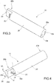
Figures 3 and 4 are perspective views of a dispensing wand for use in a device according to the present invention; -
Figure 5 is a partial view which shows on a larger scale a detail of the wand according toFigures 3 and 4 ; and -
Figure 6 is a cross-sectional view along the line VI-VI ofFigure 4 . - In
Figure 1 , the reference number 1 denotes overall a device according to the present invention for heating and frothing a quantity of milk M contained in a receptacle R, such as a glass or a cup, of any form and/or size. - The device 1 comprises an electric vibration pump 2, of the type known per se, having an intake inlet 2a connected to a water tank 3 and the outlet or delivery connected to the inlet of a heating device 4. This device 4 is of the so-called instantaneous type, otherwise known as a flow heater or transition heater.
- A
flow meter 5, for example of the turbine type, may be advantageously inserted in series with the electric pump 2, preferably between its intake inlet 2a and the tank 3, said flow meter being designed to provide electric signals indicating the flowrate of the water flowing through said electric pump. - An electric temperature sensor 6 may be conveniently associated with the heating device 4.
- The outlet of the heating device 4 can be connected to an
inlet 10a of a dispensingwand 10 via a first electric valve 7 which, in the embodiment shown, is of the 3-way, dual position, normally closed type. - The electric valve 7 is able to assume normally a condition, shown in
Figure 1 , where it connects theinlet 10a of the dispensingwand 10 to adischarge container 103, such as a drip tray, and a second condition where it connects theinlet 10a of saidwand 10 to the outlet of the instantaneous heating device 4. - The outlet of the heater 4 can also be connected to a
second inlet 10b of the dispensingwand 10, via a secondelectric valve 8, which is also of the 3-way, dual position, normally closed type. - The
electric valve 8 is able to assume normally the condition shown inFigure 1 , where it disconnects theinlet 10b of thewand 10 from the heating device 4 and connects saidinlet 10b to the outlet of an air compressor 9 which can be rotationally operated by means of anelectric motor 11. - The compressor 9 is intended to draw ambient air through a
filter 12, so as to supply a pressurized-air flow to thewand 10, via theelectric valve 8. - The
electric valve 8 is able to assume a second condition where it disconnects theinlet 10b of thewand 10 from the compressor 9 and connects thisinlet 10b to the outlet of the heating device 4, so as to transmit a flow of steam to saidinlet 10b of thewand 10. - In
Figure 1 thereference number 13 denotes the "node" or junction for connection between the outlet of the heating device 4 and the inlets of theelectric valves 7 and 8. Aconduit 14 extends from this "node" 13 and passes through a one-way valve 16 with a pressure threshold and leads to asteam condenser 17 and to an associated storage container such as theaforementioned drip tray 103. - In the embodiment according to
Figure 1 , the device 1 is of the stand-alone type, i.e. is not incorporated in a machine for the preparation of beverages by means of brewing, such as espresso coffee and the like. In this way the electric valve 7 may be omitted if necessary and theinlet 10a of the dispensingwand 10 could be directly connected to the outlet of the heating device 4. In fact, the electric isolating valve 7 may instead be required for example when the electric pump 2 and the heating device 4 are used in combination with a brewing unit, as shown in the diagram ofFigure 2 , which will be described further below, in order to prevent in such a case the hot water and/or steam at the outlet of the heating device 4 from unduly reaching thedispensing wand 10 when the electric pump 2 and the heating device 4 are used to send to the brewing unit a flow of hot water and/or steam for preparation of a beverage, such as espresso coffee. - In any case, in a device 1 according to the invention, the electric valve 7 is not used to control the flowrate of the steam which in the device 1 serves to heat and froth the milk M contained in the receptacle R, this flowrate instead being controlled by means of suitable controlled operation of the electric vibration pump 2.
-
Figure 2 of the attached drawings shows in schematic form a device 1 according to the present invention, in an embodiment where it is incorporated in a machine for preparing hot beverages, in particular espresso coffee, where the electric pump 2 and the heater 4 are used also for the preparation of this beverage. - In this embodiment the device 1 has substantially the same configuration as in
Figure 1 , but thejunction 13, or the outlet of the heating device 4 has, extending therefrom, aline 14 intended to supply a flow of hot water and/or steam to abrewing unit 15 of the type known per se, for the preparation of a hot beverage, in particular espresso coffee. - In the embodiment according to
Figure 2 , the one-way threshold valve 16 and thesteam condenser 17 of the device according toFigure 1 are no longer present. - As regards the rest, the device 1 according to
Figure 2 corresponds entirely and in all respects to that described with reference toFigure 1 . However, as already indicated further above, in the case of the device 1 according toFigure 2 , the presence of the electric isolating valve 7 is no longer simply optional, but is indeed necessary in order to disconnect thedispensing wand 10 from the outlet of the heating device 4 when the latter and the electric pump 2 are used together with thebrewing unit 15 for the preparation of espresso coffee or some other hot beverage. - With reference to
Figure 3 to 6 , thedispensing wand 10 in the example shown comprises abody 20 of elongate shape, for example made of food-grade plastic, having a cylindrical general form. - The
body 20 has anend 20a, the end surface or side of which has, formed therein, theinlet openings valves 7 and 8 in accordance with the diagrams shown inFigures 1 and2 . - The
opposite end 20b of thebody 20 in the example of embodiment shown forms a stepped recess defined by two surfaces orsides surface 20a is essentially parallel to the longitudinal direction of thebody 20, while thesurface 20c is essentially transverse to this direction. - The
end 20b also has a further end surface orside 20e, which is essentially transverse and relative to which thesurface 20c is axially set back, towards theend 20a of thebody 20. - Two
longitudinal conduits Figure 6 ). - The
conduit 21 extends between the inlet opening 10a and an outlet opening 10c, which is formed in thesurface 20c of thebody 20 and has an associatedejection nozzle 23 intended during use to emit a flow or jet of steam in a direction essentially parallel to the longitudinal axis of thebody 20. - The
conduit 22 extends from the inlet opening 10b (Figure 6 ) to a certain distance from the end surface orside 20e of thebody 20 and is connected to a transverse outlet passage 10d which emerges in the surface orside 20d and inside which anejector nozzle 24 is mounted. - The arrangement is such that, during use, when the distal end of the dispensing
wand 10 is immersed in the milk R, the flows of vapour and compressed air exiting from thenozzles nozzle 24. - The arrangement described above, whereby the
wand 10 emits during use an axial flow of steam and a transverse flow of compressed air, is particularly convenient for use in small-size receptacles R. - For use in relatively larger size receptacles R, such as large cups or jugs, it is also possible to use a configuration in which the functions of the
nozzles transverse nozzle 24, while the compressed air is emitted through thelongitudinal nozzle 23. - The
wand 10 is preferably provided with an electric temperature sensor, such as that indicated by 25 in the drawings. In the embodiment shown, this temperature sensor is mounted on the end surface orside 20e of the wand, so as to be operationally immersed within the milk M to be frothed and so as to heat the inside of the receptacle R. - The device 1 according to the invention comprises an electronic unit, denoted by ECU in
Figures 1 and2 . - The unit ECU has a plurality of inlets which are connected to the
flow meter 5 and thetemperature sensors 6 and 25. - This unit ECU also comprises a plurality of outlets connected to the electric vibration pump 2, the heating device 4 and the electric valves 7 and 9 and the
motor 11 associated with the air compressor 9. - A setting and
command device 30 is also connected to the unit ECU and may be used by the user to perform operation of the device 1 selectively in a plurality of different modes as regards both the temperature and degree of frothing of the milk which are required. - An operating cycle of the device according to the invention will now be described, said cycle being performed in the same way for both the embodiments according to
Figures 1 and2 . - In order to heat and froth the milk M contained in a receptacle R, the user immerses the
dispensing wand 10 in the milk, so that thenozzles temperature sensor 25 are submerged and located near the bottom of the receptacle R. - The user by means of the
setting device 30 performs activation of the heating and frothing device 1 in the desired mode. - The control unit ECU correspondingly activates the electric pump 2, the heating device 4 and the
motor 11 of the compressor 9 and also switches the electric valve 7 to the condition where it connects the outlet of the heating device 4 to theinlet 10a of thedispensing wand 10. - The
wand 10 therefore receives both a flow of steam at theinlet 10a and (via the electric valve 8) a flow of compressed air at theinlet 10b. Thenozzles wand 10 therefore emit, into the milk M contained in the receptacle R, respective intersecting flows of steam and compressed air which are therefore mixed outside the device 1 as a whole, within the milk to be frothed. - The unit ECU receives the signals provided by the
flow meter 5 and by thetemperature sensors 6 and 25. Depending on the signals provided by these sensors and depending on the operating mode set by the user via thecommand device 30, the unit ECU may modulate the flowrate of the electric pump 2, the level of heating performed in the heating device 4 and the flowrate of compressed air supplied by the compressor/motor 9, 11. - In particular, by means of the
temperature sensor 25 it is possible to check when the desired temperature for the milk M is reached. - By means of modulation of the compressed air flowrate it is possible to obtain milk with a layer of froth of variable height.
- Once the milk M inside the receptacle R has been heated and frothed by the amount corresponding to the mode selected by the user, the control unit ECU deactivates the electric pump 2, the heating device 4 and the
motor 11 of the compressor and may conveniently activate an operating cycle for cleaning and sanitization of the conduits and the nozzles of the dispensingwand 10. - For this purpose the unit ECU activates the electric pump 2 and the heating device 4 in order to generate a flow of steam and sets the
electric valves 7 and 8 to the condition where they connect the outlet of the heater 4 to theinlets wand 10. In this condition theconduits nozzles wand 10 are crossed, simultaneously, or alternately, by flows of high-temperature steam which clean them, preventing possible blockages, and sanitize them. - If, during the cleaning and sanitization cycle, the
wand 10 is introduced into a small empty container, the high-temperature steam emerging from thenozzles - After the cleaning and sanitization cycle it is possible for the user to prepare a new quantity of heated and frothed milk. It is also possible, after this new preparation operation, for the user not to remove the heated and frothed milk and to leave the dispensing
wand 10 immersed therein. In this condition (wand immersed in the milk following a cleaning cycle / preparation cycle sequence) it may happen that the milk rises back up from the receptacle R towards theelectric valve 8, via theconduit 22 of thewand 10. - In order to avoid this drawback, the unit ECU may be set so as to recognize the occurrence of such a situation and activate in this case the compressor/
motor 9, 11 for a predetermined period of time, for example a few seconds, in order to prevent the milk from rising back up towards theelectric valve 8. - The unit ECU may recognize the condition where the wand is immersed in the hot milk by analyzing the signal provided by the temperature sensor 25: if, after preparation of hot/frothed milk, the temperature detected by the
sensor 25 slowly decreases, the unit ECU assumes that thewand 10 is still immersed and activates the compressor/motor 9, 11. - If, instead, the
temperature sensor 25 indicates a temperature which suddenly drops, the unit ECU assumes that the wand is no longer immersed in the hot beverage and avoids activating the compressor/motor 9, 11. - Obviously, without altering the principle of the invention, the embodiments and the constructional details may be greatly varied with respect to that described and illustrated purely by way of a non-limiting example, without thereby departing from the scope of the invention as defined in the accompanying claims.
Claims (13)
- Device (1) for heating and frothing milk (M), for use in preparing a hot beverage such as cappuccino and the like, comprising
steam generating means (2, 4),
compressed-air generating means (9, 11), and
a dispensing wand (10) connected or adapted to be connected to the steam generating means (2, 4) and the compressed-air generating means (9, 11) and adapted to be introduced into a receptacle (R) containing the milk (M) to be heated and frothed;
wherein the dispensing wand (10) defines first and second conduits (21, 22) which are separate from each other and have respective separate inlets (10a, 10b) for connection to the steam generating means (2, 4) and the compressed-air generating means (9, 11), respectively, as well as respective separate outlets (10c, 23; 10d, 24) for dispensing during use a flow of steam and a flow of compressed air, respectively, within the milk (M) contained in said receptacle (R);
the device (1) being characterized in that said outlets (23, 24) are arranged such that the flows of steam and compressed air exiting therefrom intersect each other. - Device according to Claim 1, further comprising
a temperature sensor (25) associated with the dispensing wand (10) for providing electric signals indicative of the temperature of the milk (M) in said receptacle (R), and
a control unit (ECU) designed to control and coordinate in predetermined modes said steam generating means (2, 4) and compressed-air generating means (9, 11) depending on the signals provided by said temperature sensor (25);
the steam generating means (2, 4) comprising an electric vibration pump (2) having an intake inlet connected to a water tank (3) and the outlet or delivery connected to an instantaneous heating device (4);
the control unit (ECU) being designed to modulate the flowrate of said electric pump (21) depending on the signals provided by said temperature sensor (25). - Device according to Claim 1 or Claim 2, comprising a first electric valve (7) arranged between the steam generating means (2, 4) and the dispensing wand (10) so as to selectively allow and prevent a flow of steam to said dispensing wand (10).
- Device according to one of the preceding claims, comprising one (further) electric valve (8) arranged between the compressed-air generating means (9, 11) and the dispensing wand (10).
- Device according to Claim 3 and Claim 4, wherein said further electric valve (8) is also connected to the outlet of the heating device (4) and is adapted to selectively assume a first and a second condition, respectively, in which it connects the compressed-air generating means (9, 11) and the heating device (4), respectively, to the dispensing wand (410), so as to supply the aforementioned second conduit (22) of the dispensing wand (10) with compressed air and steam, respectively.
- Device according to one of the preceding claims, further comprising a flow meter (5) adapted to provide the control unit (ECU) with signals indicative of the flowrate of the water flowing through said electric pump (2).
- Device according to one of the preceding claims, wherein the dispensing wand (10) has an elongate shape and said conduits (21, 22) extend along the longitudinal direction thereof; the outlets (23, 24) of said conduits (21, 22) being arranged such that one outlet (23) emits a first flow along said longitudinal direction and the other outlet (24) emits a second flow along a direction intersecting said first flow.
- Device according to Claim 7, wherein said other outlet (24) of the dispensing wand (10) is arranged such that it is adapted to emit a flow substantially orthogonal to said first flow.
- Device according to Claim 7 or Claim 8, wherein the dispensing wand (10) is connected to the steam generating means (2, 4) and the compressed-air generating means (9, 11) such that its outlets (23, 24) are adapted to emit a flow of steam along said longitudinal direction and a flow of compressed air along a direction intersecting the steam flow.
- Device according to Claim 7 or Claim 8, wherein the dispensing wand (10) is connected to the steam generating means (2, 4) and the compressed-air generating means (9, 11) such that its outlets (23, 24) are adapted to emit a flow of compressed air along said longitudinal direction and a flow of steam along a direction intersecting the flow of compressed air.
- Dispensing wand (10) for use in a device (1) according to one or more of the preceding claims, comprising a body (20) with an elongate shape having, defined therein, first and second conduits (21, 22) separate from one another and having respective separate inlets (10a, 10b) for connection to the steam generating means (2, 4) and the compressed-air generating means (9, 11), respectively, as well as respective separate outlets (23, 24) for dispensing during use a flow of steam and a flow of compressed air within the milk (M) contained in said receptacle (R); said outlets (23, 24) being arranged such that the flows of steam and compressed air exiting therefrom intersect each other, wherein one outlet (24) of the dispensing wand (10) is arranged such that it is adapted to emit a flow substantially orthogonal to the flow emitted by the other outlet (23).
- Dispensing wand according to Claim 11, wherein said conduits (21, 22) extend along the longitudinal direction of the wand (10); the outlets (23, 24) of said conduits (21, 22) being arranged such that one outlet (23) emits a first flow along said longitudinal direction and the other outlet (24) emits a second flow along a direction intersecting said first flow.
- Machine for preparing hot beverages, in particular espresso coffee, comprising a device (1) for heating and frothing milk (M) according to one or more of Claims 1 to 10.
Applications Claiming Priority (2)
| Application Number | Priority Date | Filing Date | Title |
|---|---|---|---|
| ITTO20141063 | 2014-12-18 | ||
| PCT/IB2015/059402 WO2016097923A1 (en) | 2014-12-18 | 2015-12-07 | Device for heating and frothing milk and wand for such a device |
Publications (2)
| Publication Number | Publication Date |
|---|---|
| EP3232878A1 EP3232878A1 (en) | 2017-10-25 |
| EP3232878B1 true EP3232878B1 (en) | 2019-03-06 |
Family
ID=52472444
Family Applications (1)
| Application Number | Title | Priority Date | Filing Date |
|---|---|---|---|
| EP15818054.7A Active EP3232878B1 (en) | 2014-12-18 | 2015-12-07 | Device for heating and frothing milk and wand for such a device |
Country Status (5)
| Country | Link |
|---|---|
| US (1) | US11122928B2 (en) |
| EP (1) | EP3232878B1 (en) |
| CN (1) | CN106998951B (en) |
| AU (1) | AU2015365471B2 (en) |
| WO (1) | WO2016097923A1 (en) |
Families Citing this family (12)
| Publication number | Priority date | Publication date | Assignee | Title |
|---|---|---|---|---|
| CH710913B1 (en) * | 2015-03-26 | 2020-03-31 | Steiner Ag Weggis | Process and steam lance for producing milk foam. |
| IT201600080088A1 (en) * | 2016-07-29 | 2018-01-29 | Lavazza Luigi Spa | MACHINE FOR THE PREPARATION OF BEVERAGES, IN PARTICULAR ESPRESSO COFFEE, VALVE AND VALVE GROUP CAN BE USED IN SUCH A MACHINE |
| MX2019009740A (en) * | 2017-02-15 | 2020-01-27 | 2266170 Ontario Inc | Beverage preparation and infusion system. |
| CA3065342A1 (en) * | 2017-06-05 | 2018-12-13 | Keurig Green Mountain, Inc. | Vent orifice and filter for beverage machine |
| US11083328B2 (en) | 2017-06-22 | 2021-08-10 | Starbucks Corporation | Apparatus and method for foaming a beverage |
| IT201800001717A1 (en) * | 2018-01-24 | 2019-07-24 | De Longhi Appliances Srl | DEVICE FOR HEATING AND EMULSION OF BEVERAGES |
| IT201800003932A1 (en) * | 2018-03-26 | 2019-09-26 | Rancilio Group Spa | Method for controlling the temperature of milk in a device for heating and / or frothing milk |
| US11058250B2 (en) | 2018-09-06 | 2021-07-13 | Starbucks Corporation | Apparatus for foaming a beverage |
| IT201900009249A1 (en) * | 2019-06-17 | 2020-12-17 | Gruppo Cimbali Spa | Milk whipping apparatus and method for whipping milk using this apparatus |
| IT201900009240A1 (en) * | 2019-06-17 | 2020-12-17 | Gruppo Cimbali Spa | Dispensing lance for a milk frothing apparatus and an apparatus for frothing milk with this lance |
| IT201900012693A1 (en) * | 2019-07-23 | 2021-01-23 | Cma Macch Per Caffe Srl | DEVICE AND PROCEDURE FOR THE PREPARATION OF FOAMED MILK |
| DE102022103537A1 (en) * | 2022-02-15 | 2023-08-17 | Next Level Coffee GmbH | Steam lance for a coffee maker |
Family Cites Families (14)
| Publication number | Priority date | Publication date | Assignee | Title |
|---|---|---|---|---|
| CH673212A5 (en) * | 1986-09-24 | 1990-02-28 | Krups Stiftung | |
| DE3842206C2 (en) | 1988-12-15 | 1994-05-26 | Krups Fa Robert | Device for preparing cappuccino |
| DE8816009U1 (en) * | 1988-12-23 | 1990-04-19 | Bosch-Siemens Hausgeraete Gmbh, 8000 Muenchen, De | |
| DE4220986A1 (en) | 1992-06-26 | 1994-01-05 | Gotthard Dipl Ing Mahlich | Device for preparing milk foam for cappuccino |
| US6203837B1 (en) * | 1998-10-06 | 2001-03-20 | Xcafe' Llc | Coffee system |
| AU2002309254A1 (en) | 2002-05-06 | 2003-11-17 | Cimbali, S.P.A. | Device for heating and working up milk |
| ITTO20030271A1 (en) * | 2003-04-09 | 2004-10-10 | Rancilio Macchine Caffe | AUTOMATIC STEAM DISPENSER DEVICE FOR THE PREPARATION OF HOT AND / OR FOAM DRINKS. |
| ATE404094T1 (en) * | 2004-12-21 | 2008-08-15 | Inventum Holding B V | DEVICE FOR PREPARING A DRINK |
| DE602007000812D1 (en) * | 2007-01-23 | 2009-05-14 | Rancilio Macchine Caffe | Device for heating and / or frothing a beverage |
| DE102009025986A1 (en) * | 2009-06-17 | 2011-03-31 | Cafina Ag | Device for heating and frothing milk |
| JP5661759B2 (en) * | 2010-06-03 | 2015-01-28 | パナソニックIpマネジメント株式会社 | coffee maker |
| CN102958409A (en) * | 2010-07-08 | 2013-03-06 | 皇家飞利浦电子股份有限公司 | Milk frothing system |
| ITMI20131726A1 (en) * | 2013-10-17 | 2015-04-18 | Swiss Caffe Asia Ltd | AUTOMATIC MACHINE FOR THE PREPARATION OF BEVERAGES, WHICH ESPRESSO COFFEE, CAPPUCCINO AND SIMILAR. |
| DE102014108415B3 (en) * | 2014-06-16 | 2015-11-19 | Eugster/Frismag Ag | Beverage preparation device and operating method |
-
2015
- 2015-12-07 CN CN201580068611.2A patent/CN106998951B/en active Active
- 2015-12-07 AU AU2015365471A patent/AU2015365471B2/en active Active
- 2015-12-07 WO PCT/IB2015/059402 patent/WO2016097923A1/en active Application Filing
- 2015-12-07 EP EP15818054.7A patent/EP3232878B1/en active Active
- 2015-12-07 US US15/534,272 patent/US11122928B2/en active Active
Non-Patent Citations (1)
| Title |
|---|
| None * |
Also Published As
| Publication number | Publication date |
|---|---|
| CN106998951B (en) | 2021-01-26 |
| EP3232878A1 (en) | 2017-10-25 |
| US20180353001A1 (en) | 2018-12-13 |
| AU2015365471B2 (en) | 2020-02-27 |
| AU2015365471A1 (en) | 2017-07-27 |
| CN106998951A (en) | 2017-08-01 |
| US11122928B2 (en) | 2021-09-21 |
| WO2016097923A1 (en) | 2016-06-23 |
Similar Documents
| Publication | Publication Date | Title |
|---|---|---|
| EP3232878B1 (en) | Device for heating and frothing milk and wand for such a device | |
| US9038529B2 (en) | Coffee machine comprising a frothing device and means for cleaning the frothing device and a milk suction line and process for rinsing the milk suction line | |
| US9788686B2 (en) | Electrically operated drink maker, in particular electrically operated coffee machine, with steam lance for frothing up milk | |
| JP6095695B2 (en) | Liquid supply tank with expansion chamber | |
| EP3313245B1 (en) | Device for preparing frothy milk | |
| JP5203947B2 (en) | Beverage machine drain | |
| CN101573063B (en) | Method for dispensing milk portions in drink preparation machines | |
| US8337635B2 (en) | Beverage preparation device with in-line scale removal system and descaling method using such system | |
| US9060646B2 (en) | Milk frothing with pressurized gas | |
| EP2299881B1 (en) | Device for whisking milk and method for cleaning such a device | |
| CN106998953B (en) | Machine for preparing beverages, in particular espresso coffee | |
| US20130040028A1 (en) | Circulatory milk frothing device | |
| CN110833331B (en) | Device for preparing a liquid with an integrated rinsing system and rinsing method | |
| CN108135390A (en) | Beverage preparing machine | |
| EP3697270B1 (en) | Beverage vending machine | |
| WO2018226633A1 (en) | Pressure relief valve configuration for beverage machine | |
| EP3771371B1 (en) | Coffee machine drainage channel | |
| US20220313004A1 (en) | Method and apparatus for beverage frothing | |
| CA3065342A1 (en) | Vent orifice and filter for beverage machine |
Legal Events
| Date | Code | Title | Description |
|---|---|---|---|
| STAA | Information on the status of an ep patent application or granted ep patent |
Free format text: STATUS: THE INTERNATIONAL PUBLICATION HAS BEEN MADE |
|
| PUAI | Public reference made under article 153(3) epc to a published international application that has entered the european phase |
Free format text: ORIGINAL CODE: 0009012 |
|
| STAA | Information on the status of an ep patent application or granted ep patent |
Free format text: STATUS: REQUEST FOR EXAMINATION WAS MADE |
|
| 17P | Request for examination filed |
Effective date: 20170523 |
|
| AK | Designated contracting states |
Kind code of ref document: A1 Designated state(s): AL AT BE BG CH CY CZ DE DK EE ES FI FR GB GR HR HU IE IS IT LI LT LU LV MC MK MT NL NO PL PT RO RS SE SI SK SM TR |
|
| AX | Request for extension of the european patent |
Extension state: BA ME |
|
| DAV | Request for validation of the european patent (deleted) | ||
| DAX | Request for extension of the european patent (deleted) | ||
| GRAP | Despatch of communication of intention to grant a patent |
Free format text: ORIGINAL CODE: EPIDOSNIGR1 |
|
| STAA | Information on the status of an ep patent application or granted ep patent |
Free format text: STATUS: GRANT OF PATENT IS INTENDED |
|
| INTG | Intention to grant announced |
Effective date: 20180920 |
|
| GRAS | Grant fee paid |
Free format text: ORIGINAL CODE: EPIDOSNIGR3 |
|
| GRAA | (expected) grant |
Free format text: ORIGINAL CODE: 0009210 |
|
| STAA | Information on the status of an ep patent application or granted ep patent |
Free format text: STATUS: THE PATENT HAS BEEN GRANTED |
|
| AK | Designated contracting states |
Kind code of ref document: B1 Designated state(s): AL AT BE BG CH CY CZ DE DK EE ES FI FR GB GR HR HU IE IS IT LI LT LU LV MC MK MT NL NO PL PT RO RS SE SI SK SM TR |
|
| REG | Reference to a national code |
Ref country code: GB Ref legal event code: FG4D |
|
| REG | Reference to a national code |
Ref country code: CH Ref legal event code: EP Ref country code: AT Ref legal event code: REF Ref document number: 1103429 Country of ref document: AT Kind code of ref document: T Effective date: 20190315 |
|
| REG | Reference to a national code |
Ref country code: DE Ref legal event code: R096 Ref document number: 602015026041 Country of ref document: DE |
|
| REG | Reference to a national code |
Ref country code: IE Ref legal event code: FG4D |
|
| REG | Reference to a national code |
Ref country code: NL Ref legal event code: MP Effective date: 20190306 |
|
| REG | Reference to a national code |
Ref country code: LT Ref legal event code: MG4D |
|
| PG25 | Lapsed in a contracting state [announced via postgrant information from national office to epo] |
Ref country code: SE Free format text: LAPSE BECAUSE OF FAILURE TO SUBMIT A TRANSLATION OF THE DESCRIPTION OR TO PAY THE FEE WITHIN THE PRESCRIBED TIME-LIMIT Effective date: 20190306 Ref country code: NO Free format text: LAPSE BECAUSE OF FAILURE TO SUBMIT A TRANSLATION OF THE DESCRIPTION OR TO PAY THE FEE WITHIN THE PRESCRIBED TIME-LIMIT Effective date: 20190606 Ref country code: FI Free format text: LAPSE BECAUSE OF FAILURE TO SUBMIT A TRANSLATION OF THE DESCRIPTION OR TO PAY THE FEE WITHIN THE PRESCRIBED TIME-LIMIT Effective date: 20190306 Ref country code: LT Free format text: LAPSE BECAUSE OF FAILURE TO SUBMIT A TRANSLATION OF THE DESCRIPTION OR TO PAY THE FEE WITHIN THE PRESCRIBED TIME-LIMIT Effective date: 20190306 |
|
| PG25 | Lapsed in a contracting state [announced via postgrant information from national office to epo] |
Ref country code: NL Free format text: LAPSE BECAUSE OF FAILURE TO SUBMIT A TRANSLATION OF THE DESCRIPTION OR TO PAY THE FEE WITHIN THE PRESCRIBED TIME-LIMIT Effective date: 20190306 Ref country code: HR Free format text: LAPSE BECAUSE OF FAILURE TO SUBMIT A TRANSLATION OF THE DESCRIPTION OR TO PAY THE FEE WITHIN THE PRESCRIBED TIME-LIMIT Effective date: 20190306 Ref country code: RS Free format text: LAPSE BECAUSE OF FAILURE TO SUBMIT A TRANSLATION OF THE DESCRIPTION OR TO PAY THE FEE WITHIN THE PRESCRIBED TIME-LIMIT Effective date: 20190306 Ref country code: GR Free format text: LAPSE BECAUSE OF FAILURE TO SUBMIT A TRANSLATION OF THE DESCRIPTION OR TO PAY THE FEE WITHIN THE PRESCRIBED TIME-LIMIT Effective date: 20190607 Ref country code: BG Free format text: LAPSE BECAUSE OF FAILURE TO SUBMIT A TRANSLATION OF THE DESCRIPTION OR TO PAY THE FEE WITHIN THE PRESCRIBED TIME-LIMIT Effective date: 20190606 Ref country code: LV Free format text: LAPSE BECAUSE OF FAILURE TO SUBMIT A TRANSLATION OF THE DESCRIPTION OR TO PAY THE FEE WITHIN THE PRESCRIBED TIME-LIMIT Effective date: 20190306 |
|
| REG | Reference to a national code |
Ref country code: AT Ref legal event code: MK05 Ref document number: 1103429 Country of ref document: AT Kind code of ref document: T Effective date: 20190306 |
|
| PG25 | Lapsed in a contracting state [announced via postgrant information from national office to epo] |
Ref country code: ES Free format text: LAPSE BECAUSE OF FAILURE TO SUBMIT A TRANSLATION OF THE DESCRIPTION OR TO PAY THE FEE WITHIN THE PRESCRIBED TIME-LIMIT Effective date: 20190306 Ref country code: PT Free format text: LAPSE BECAUSE OF FAILURE TO SUBMIT A TRANSLATION OF THE DESCRIPTION OR TO PAY THE FEE WITHIN THE PRESCRIBED TIME-LIMIT Effective date: 20190706 Ref country code: AL Free format text: LAPSE BECAUSE OF FAILURE TO SUBMIT A TRANSLATION OF THE DESCRIPTION OR TO PAY THE FEE WITHIN THE PRESCRIBED TIME-LIMIT Effective date: 20190306 Ref country code: CZ Free format text: LAPSE BECAUSE OF FAILURE TO SUBMIT A TRANSLATION OF THE DESCRIPTION OR TO PAY THE FEE WITHIN THE PRESCRIBED TIME-LIMIT Effective date: 20190306 Ref country code: RO Free format text: LAPSE BECAUSE OF FAILURE TO SUBMIT A TRANSLATION OF THE DESCRIPTION OR TO PAY THE FEE WITHIN THE PRESCRIBED TIME-LIMIT Effective date: 20190306 Ref country code: EE Free format text: LAPSE BECAUSE OF FAILURE TO SUBMIT A TRANSLATION OF THE DESCRIPTION OR TO PAY THE FEE WITHIN THE PRESCRIBED TIME-LIMIT Effective date: 20190306 Ref country code: SK Free format text: LAPSE BECAUSE OF FAILURE TO SUBMIT A TRANSLATION OF THE DESCRIPTION OR TO PAY THE FEE WITHIN THE PRESCRIBED TIME-LIMIT Effective date: 20190306 |
|
| PG25 | Lapsed in a contracting state [announced via postgrant information from national office to epo] |
Ref country code: PL Free format text: LAPSE BECAUSE OF FAILURE TO SUBMIT A TRANSLATION OF THE DESCRIPTION OR TO PAY THE FEE WITHIN THE PRESCRIBED TIME-LIMIT Effective date: 20190306 Ref country code: SM Free format text: LAPSE BECAUSE OF FAILURE TO SUBMIT A TRANSLATION OF THE DESCRIPTION OR TO PAY THE FEE WITHIN THE PRESCRIBED TIME-LIMIT Effective date: 20190306 |
|
| REG | Reference to a national code |
Ref country code: DE Ref legal event code: R097 Ref document number: 602015026041 Country of ref document: DE |
|
| PG25 | Lapsed in a contracting state [announced via postgrant information from national office to epo] |
Ref country code: IS Free format text: LAPSE BECAUSE OF FAILURE TO SUBMIT A TRANSLATION OF THE DESCRIPTION OR TO PAY THE FEE WITHIN THE PRESCRIBED TIME-LIMIT Effective date: 20190706 Ref country code: AT Free format text: LAPSE BECAUSE OF FAILURE TO SUBMIT A TRANSLATION OF THE DESCRIPTION OR TO PAY THE FEE WITHIN THE PRESCRIBED TIME-LIMIT Effective date: 20190306 |
|
| PLBE | No opposition filed within time limit |
Free format text: ORIGINAL CODE: 0009261 |
|
| STAA | Information on the status of an ep patent application or granted ep patent |
Free format text: STATUS: NO OPPOSITION FILED WITHIN TIME LIMIT |
|
| PG25 | Lapsed in a contracting state [announced via postgrant information from national office to epo] |
Ref country code: DK Free format text: LAPSE BECAUSE OF FAILURE TO SUBMIT A TRANSLATION OF THE DESCRIPTION OR TO PAY THE FEE WITHIN THE PRESCRIBED TIME-LIMIT Effective date: 20190306 |
|
| 26N | No opposition filed |
Effective date: 20191209 |
|
| PG25 | Lapsed in a contracting state [announced via postgrant information from national office to epo] |
Ref country code: SI Free format text: LAPSE BECAUSE OF FAILURE TO SUBMIT A TRANSLATION OF THE DESCRIPTION OR TO PAY THE FEE WITHIN THE PRESCRIBED TIME-LIMIT Effective date: 20190306 |
|
| PG25 | Lapsed in a contracting state [announced via postgrant information from national office to epo] |
Ref country code: TR Free format text: LAPSE BECAUSE OF FAILURE TO SUBMIT A TRANSLATION OF THE DESCRIPTION OR TO PAY THE FEE WITHIN THE PRESCRIBED TIME-LIMIT Effective date: 20190306 |
|
| REG | Reference to a national code |
Ref country code: CH Ref legal event code: PL |
|
| REG | Reference to a national code |
Ref country code: BE Ref legal event code: MM Effective date: 20191231 |
|
| PG25 | Lapsed in a contracting state [announced via postgrant information from national office to epo] |
Ref country code: MC Free format text: LAPSE BECAUSE OF FAILURE TO SUBMIT A TRANSLATION OF THE DESCRIPTION OR TO PAY THE FEE WITHIN THE PRESCRIBED TIME-LIMIT Effective date: 20190306 |
|
| PG25 | Lapsed in a contracting state [announced via postgrant information from national office to epo] |
Ref country code: LU Free format text: LAPSE BECAUSE OF NON-PAYMENT OF DUE FEES Effective date: 20191207 Ref country code: IE Free format text: LAPSE BECAUSE OF NON-PAYMENT OF DUE FEES Effective date: 20191207 |
|
| PG25 | Lapsed in a contracting state [announced via postgrant information from national office to epo] |
Ref country code: CH Free format text: LAPSE BECAUSE OF NON-PAYMENT OF DUE FEES Effective date: 20191231 Ref country code: LI Free format text: LAPSE BECAUSE OF NON-PAYMENT OF DUE FEES Effective date: 20191231 Ref country code: BE Free format text: LAPSE BECAUSE OF NON-PAYMENT OF DUE FEES Effective date: 20191231 |
|
| PG25 | Lapsed in a contracting state [announced via postgrant information from national office to epo] |
Ref country code: CY Free format text: LAPSE BECAUSE OF FAILURE TO SUBMIT A TRANSLATION OF THE DESCRIPTION OR TO PAY THE FEE WITHIN THE PRESCRIBED TIME-LIMIT Effective date: 20190306 |
|
| PG25 | Lapsed in a contracting state [announced via postgrant information from national office to epo] |
Ref country code: HU Free format text: LAPSE BECAUSE OF FAILURE TO SUBMIT A TRANSLATION OF THE DESCRIPTION OR TO PAY THE FEE WITHIN THE PRESCRIBED TIME-LIMIT; INVALID AB INITIO Effective date: 20151207 Ref country code: MT Free format text: LAPSE BECAUSE OF FAILURE TO SUBMIT A TRANSLATION OF THE DESCRIPTION OR TO PAY THE FEE WITHIN THE PRESCRIBED TIME-LIMIT Effective date: 20190306 |
|
| PG25 | Lapsed in a contracting state [announced via postgrant information from national office to epo] |
Ref country code: MK Free format text: LAPSE BECAUSE OF FAILURE TO SUBMIT A TRANSLATION OF THE DESCRIPTION OR TO PAY THE FEE WITHIN THE PRESCRIBED TIME-LIMIT Effective date: 20190306 |
|
| PGFP | Annual fee paid to national office [announced via postgrant information from national office to epo] |
Ref country code: DE Payment date: 20221227 Year of fee payment: 8 |
|
| P01 | Opt-out of the competence of the unified patent court (upc) registered |
Effective date: 20230601 |
|
| PGFP | Annual fee paid to national office [announced via postgrant information from national office to epo] |
Ref country code: GB Payment date: 20231222 Year of fee payment: 9 |
|
| PGFP | Annual fee paid to national office [announced via postgrant information from national office to epo] |
Ref country code: IT Payment date: 20231229 Year of fee payment: 9 Ref country code: FR Payment date: 20231226 Year of fee payment: 9 |