EP3232447A1 - Cable assembly and cable assembly manufacturing method - Google Patents
Cable assembly and cable assembly manufacturing method Download PDFInfo
- Publication number
- EP3232447A1 EP3232447A1 EP15868092.6A EP15868092A EP3232447A1 EP 3232447 A1 EP3232447 A1 EP 3232447A1 EP 15868092 A EP15868092 A EP 15868092A EP 3232447 A1 EP3232447 A1 EP 3232447A1
- Authority
- EP
- European Patent Office
- Prior art keywords
- electroconductive
- wire
- end portion
- wires
- cable assembly
- Prior art date
- Legal status (The legal status is an assumption and is not a legal conclusion. Google has not performed a legal analysis and makes no representation as to the accuracy of the status listed.)
- Granted
Links
- 238000004519 manufacturing process Methods 0.000 title claims abstract description 45
- 239000004020 conductor Substances 0.000 claims abstract description 85
- 239000012212 insulator Substances 0.000 claims abstract description 78
- 238000000034 method Methods 0.000 claims abstract description 29
- 238000004804 winding Methods 0.000 claims description 47
- 239000002184 metal Substances 0.000 description 8
- 229910052751 metal Inorganic materials 0.000 description 8
- 239000002131 composite material Substances 0.000 description 7
- 238000012986 modification Methods 0.000 description 7
- 230000004048 modification Effects 0.000 description 7
- 239000007767 bonding agent Substances 0.000 description 6
- 230000000694 effects Effects 0.000 description 6
- 230000008054 signal transmission Effects 0.000 description 6
- 238000005476 soldering Methods 0.000 description 6
- 239000000853 adhesive Substances 0.000 description 4
- 230000005540 biological transmission Effects 0.000 description 4
- 238000005259 measurement Methods 0.000 description 4
- 230000000712 assembly Effects 0.000 description 3
- 238000000429 assembly Methods 0.000 description 3
- 238000010137 moulding (plastic) Methods 0.000 description 3
- 239000011347 resin Substances 0.000 description 3
- 229920005989 resin Polymers 0.000 description 3
- RYGMFSIKBFXOCR-UHFFFAOYSA-N Copper Chemical compound [Cu] RYGMFSIKBFXOCR-UHFFFAOYSA-N 0.000 description 2
- 229910052802 copper Inorganic materials 0.000 description 2
- 239000010949 copper Substances 0.000 description 2
- WABPQHHGFIMREM-UHFFFAOYSA-N lead(0) Chemical compound [Pb] WABPQHHGFIMREM-UHFFFAOYSA-N 0.000 description 2
- 230000013011 mating Effects 0.000 description 2
- 229910000679 solder Inorganic materials 0.000 description 2
- 239000000470 constituent Substances 0.000 description 1
- 239000000463 material Substances 0.000 description 1
Images


Classifications
-
- H—ELECTRICITY
- H05—ELECTRIC TECHNIQUES NOT OTHERWISE PROVIDED FOR
- H05K—PRINTED CIRCUITS; CASINGS OR CONSTRUCTIONAL DETAILS OF ELECTRIC APPARATUS; MANUFACTURE OF ASSEMBLAGES OF ELECTRICAL COMPONENTS
- H05K9/00—Screening of apparatus or components against electric or magnetic fields
- H05K9/0073—Shielding materials
- H05K9/0098—Shielding materials for shielding electrical cables
-
- H—ELECTRICITY
- H01—ELECTRIC ELEMENTS
- H01R—ELECTRICALLY-CONDUCTIVE CONNECTIONS; STRUCTURAL ASSOCIATIONS OF A PLURALITY OF MUTUALLY-INSULATED ELECTRICAL CONNECTING ELEMENTS; COUPLING DEVICES; CURRENT COLLECTORS
- H01R13/00—Details of coupling devices of the kinds covered by groups H01R12/70 or H01R24/00 - H01R33/00
- H01R13/646—Details of coupling devices of the kinds covered by groups H01R12/70 or H01R24/00 - H01R33/00 specially adapted for high-frequency, e.g. structures providing an impedance match or phase match
- H01R13/6473—Impedance matching
-
- H—ELECTRICITY
- H01—ELECTRIC ELEMENTS
- H01B—CABLES; CONDUCTORS; INSULATORS; SELECTION OF MATERIALS FOR THEIR CONDUCTIVE, INSULATING OR DIELECTRIC PROPERTIES
- H01B11/00—Communication cables or conductors
- H01B11/002—Pair constructions
-
- H—ELECTRICITY
- H01—ELECTRIC ELEMENTS
- H01B—CABLES; CONDUCTORS; INSULATORS; SELECTION OF MATERIALS FOR THEIR CONDUCTIVE, INSULATING OR DIELECTRIC PROPERTIES
- H01B11/00—Communication cables or conductors
- H01B11/02—Cables with twisted pairs or quads
- H01B11/06—Cables with twisted pairs or quads with means for reducing effects of electromagnetic or electrostatic disturbances, e.g. screens
-
- H—ELECTRICITY
- H01—ELECTRIC ELEMENTS
- H01B—CABLES; CONDUCTORS; INSULATORS; SELECTION OF MATERIALS FOR THEIR CONDUCTIVE, INSULATING OR DIELECTRIC PROPERTIES
- H01B13/00—Apparatus or processes specially adapted for manufacturing conductors or cables
-
- H—ELECTRICITY
- H01—ELECTRIC ELEMENTS
- H01B—CABLES; CONDUCTORS; INSULATORS; SELECTION OF MATERIALS FOR THEIR CONDUCTIVE, INSULATING OR DIELECTRIC PROPERTIES
- H01B13/00—Apparatus or processes specially adapted for manufacturing conductors or cables
- H01B13/22—Sheathing; Armouring; Screening; Applying other protective layers
- H01B13/26—Sheathing; Armouring; Screening; Applying other protective layers by winding, braiding or longitudinal lapping
-
- H—ELECTRICITY
- H01—ELECTRIC ELEMENTS
- H01B—CABLES; CONDUCTORS; INSULATORS; SELECTION OF MATERIALS FOR THEIR CONDUCTIVE, INSULATING OR DIELECTRIC PROPERTIES
- H01B7/00—Insulated conductors or cables characterised by their form
-
- H—ELECTRICITY
- H01—ELECTRIC ELEMENTS
- H01B—CABLES; CONDUCTORS; INSULATORS; SELECTION OF MATERIALS FOR THEIR CONDUCTIVE, INSULATING OR DIELECTRIC PROPERTIES
- H01B7/00—Insulated conductors or cables characterised by their form
- H01B7/17—Protection against damage caused by external factors, e.g. sheaths or armouring
-
- H—ELECTRICITY
- H05—ELECTRIC TECHNIQUES NOT OTHERWISE PROVIDED FOR
- H05K—PRINTED CIRCUITS; CASINGS OR CONSTRUCTIONAL DETAILS OF ELECTRIC APPARATUS; MANUFACTURE OF ASSEMBLAGES OF ELECTRICAL COMPONENTS
- H05K1/00—Printed circuits
- H05K1/02—Details
- H05K1/0213—Electrical arrangements not otherwise provided for
- H05K1/0237—High frequency adaptations
-
- H—ELECTRICITY
- H05—ELECTRIC TECHNIQUES NOT OTHERWISE PROVIDED FOR
- H05K—PRINTED CIRCUITS; CASINGS OR CONSTRUCTIONAL DETAILS OF ELECTRIC APPARATUS; MANUFACTURE OF ASSEMBLAGES OF ELECTRICAL COMPONENTS
- H05K3/00—Apparatus or processes for manufacturing printed circuits
- H05K3/30—Assembling printed circuits with electric components, e.g. with resistor
- H05K3/32—Assembling printed circuits with electric components, e.g. with resistor electrically connecting electric components or wires to printed circuits
-
- H—ELECTRICITY
- H05—ELECTRIC TECHNIQUES NOT OTHERWISE PROVIDED FOR
- H05K—PRINTED CIRCUITS; CASINGS OR CONSTRUCTIONAL DETAILS OF ELECTRIC APPARATUS; MANUFACTURE OF ASSEMBLAGES OF ELECTRICAL COMPONENTS
- H05K9/00—Screening of apparatus or components against electric or magnetic fields
-
- H—ELECTRICITY
- H01—ELECTRIC ELEMENTS
- H01R—ELECTRICALLY-CONDUCTIVE CONNECTIONS; STRUCTURAL ASSOCIATIONS OF A PLURALITY OF MUTUALLY-INSULATED ELECTRICAL CONNECTING ELEMENTS; COUPLING DEVICES; CURRENT COLLECTORS
- H01R13/00—Details of coupling devices of the kinds covered by groups H01R12/70 or H01R24/00 - H01R33/00
- H01R13/648—Protective earth or shield arrangements on coupling devices, e.g. anti-static shielding
- H01R13/658—High frequency shielding arrangements, e.g. against EMI [Electro-Magnetic Interference] or EMP [Electro-Magnetic Pulse]
- H01R13/6591—Specific features or arrangements of connection of shield to conductive members
- H01R13/6592—Specific features or arrangements of connection of shield to conductive members the conductive member being a shielded cable
Definitions
- the invention relates to cable assemblies and methods for manufacturing the cable assemblies.
- a common composite cable has a tuboid outer insulator, a shield conductor inside the outer insulator, and a plurality of signal wires inside the shield conductor.
- an end portion of the outer insulator and an end portion of the shield conductor of the composite cable are cut away such that an end portion of the signal wire protrudes from the outer insulator and the shield conductor.
- the protruding end portion of each signal wire has a higher impedance than that of a portion of the signal wire that is located inside the shield conductor and the outer insulator (hereinafter referred to as an inner portion). In other words, there is an impedance mismatch in each signal wire between its end portion and the inner portion.
- Patent Literature 1 identified below discloses a first cable assembly which may resolve impedance mismatch in a signal wire as described above.
- Patent Literature 2 identified below discloses a second cable assembly which may resolve impedance mismatch in a signal wire as described above.
- the first cable assembly includes a composite cable, a circuit board, a heat-shrinkable tube being an insulator.
- the composite cable includes two signal wires for differential transmission, a drain wire, and a shield conductor.
- the signal and drain wires are disposed inside the tuboid shield conductor. A lengthwise end portion of the shield conductor is cut away such as to protrude end portions of the signal wires and the drain wire from the shield conductor.
- the protruding end portions of the signal and drain wires are respectively connected to electrodes on the circuit board.
- the protruding end portions of the signal and drain wires, excluding tip portions of the end portions, are received in and covered with the heat-shrinkable tube.
- the second cable assembly includes a composite cable, a connector, and a bilayer heat-shrinkable tube.
- the composite cable includes two signal wires for differential transmission, a drain wire, a shield conductor, and an outer insulator.
- the tuboid shield conductor is disposed inside the tuboid outer insulator.
- the signal and drain wires are disposed inside the shield conductor. Lengthwise end portions of the shield conductor and the outer insulator are cut away such as to protrude end portions of the signal and drain wires from the shield conductor and the outer insulator.
- the protruding end portions of the signal and drain wires are respectively connected to terminals of the connector.
- the end portions of the signal and drain wires are received in and covered with the tuboid bilayer heat-shrinkable tube.
- the inner layer of the bilayer heat-shrinkable tube is an electroconductive layer, and the outer layer is an insulator.
- the protruding end portions of the signal and drain wires are covered with the heat-shrinkable tube, which suppresses impedance increases at the end portions of the signal and drain wires to match between the end portions and other portions.
- the invention is devised in view of the above circumstances to provide a cable assembly with reduced characteristic impedance at a protruding end portion of a first wire of a cable and configured for easy manufacture, and to provide a method for manufacturing the cable assembly.
- a cable assembly of the invention includes a first connecting member having electrical conductivity, a cable, and an electroconductive member.
- the cable includes an outer insulator, a shield conductor disposed inside the outer insulator, and at least one first wire.
- the first wire is a signal wire disposed inside the shield conductor.
- the first wire includes a protruding portion protruding substantially in a first direction from the shield conductor and the outer insulator.
- a core wire of the protruding portion is connected to the first connecting member.
- the first direction is the longitudinal direction of the cable.
- the electroconductive member is an electroconductive plate or electroconductive tape wound around at least a part in the first direction of the protruding portion.
- the cable assembly of this aspect provides the following technical features and effects. Firstly, impedance is lowered in the protruding portion of the first wire because of the electroconductive member is wound around at least the part of the protruding portion of the first wire. This contributes to matched impedances between the protruding portion of the first wire and the portion of the first wire located inside the shield conductor and the outer insulator. Secondly, the cable assembly is easy to manufacture. This is because the electroconductive member provided as the electroconductive plate or electroconductive tape is simply wound around at least the part of the protruding portion, thereby greatly facilitating attachment of the electroconductive member to the protruding portion.
- a pair of the first connecting members may be provided.
- the cable may include a pair of first wires.
- the electroconductive member may be wound around at least the parts of the protruding portions of the first wires.
- the cable assembly of this aspect is more easily manufacturable. Even if the protruding portions of the first wires are spaced from each other, the electroconductive member can be wound around the at least parts of the protruding portions while bringing the protruding portions closer to each other.
- the first connecting members may be spaced apart from each other in a second direction, the second direction crossing the first direction.
- the first wires may be configured to transmit a differential signal.
- the electroconductive member may be wound around at least the parts of the protruding portions of the first wires such that a distance in the second direction between the parts of the protruding portions of the first wires is smaller than a distance in the second direction between the first connecting members.
- impedance is further lowered in the protruding portion because the distance in the second direction between the parts of the protruding portions of the first wires is smaller than the distance in the second direction between the first connecting members. This contributes to matched impedances between the protruding portions of the first wires and the portions of the first wires located inside the shield conductor and the outer insulator.
- the electroconductive member may include a first end portion and a second end portion opposite to the first end portion.
- the electroconductive member may be wound around the at least part of the protruding portion such that at least one of the first and second end portions is in contact with the electroconductive member.
- it is easy to wind the electroconductive member around the protruding portion. This is because it is desirable to wind the electroconductive member around the at least part of the protruding portion such that at least one of the first and second end portions is in contact with the electroconductive member.
- the electroconductive member may be wound around the at least part of the protruding portion such that the first end portion and the second end portion face each other with a clearance therebetween.
- the electroconductive member may float electrically.
- the cable assembly of this aspect is more easily manufacturable. This is because there is no need to electrically connect the electroconductive member to other component.
- the electroconductive member may be electrically connected to the shield conductor of the cable.
- the electroconductive member can be easily grounded through the shield conductor.
- the cable assembly of any aspect described above may further include a shield case at least covering the protruding portion of the first wire, the electroconductive member, and a connection point at which the core wire of the protruding portion is connected to the first connecting member.
- the electroconductive member may be electrically connected to the shield case.
- the electroconductive member can be easily grounded through the shield case.
- the cable assembly of any aspect described above may further include a second connecting member having electrical conductivity.
- the cable may further include a second wire inside the shield conductor.
- the second wire may be other than a signal wire and include a protruding portion.
- the protruding portion of the second wire may protrude in the first direction from the shield conductor and the outer insulator.
- a core wire of the protruding portion of the second wire may be connected to the second connecting member.
- the electroconductive member may be wound only around the at least parts of the protruding portions of the first wires.
- the second connecting member may be disposed on one side in a third direction relative to the first connecting members, the third direction crossing the first and second directions.
- the protruding portion of the second wire may be disposed on the one side in the third direction relative to the protruding portions of the first wires.
- the cable assembly of this aspect is more easily manufacturable for the following reason. As the second connecting member and the protruding portion of the second wire are located on the one side in the third direction relative to the first connecting members and the protruding portions of the first wires, the second wire is not likely to obstruct the winding of the electroconductive member around the at least part of the protruding portion of the first wires.
- the cable assembly of any aspect described above may further include an insulating body holding the first and second connecting members.
- the first and second connecting members may be terminals.
- the body may be replaced with a circuit board.
- the first and second connecting members may not be terminals but electrodes on the circuit board.
- a method for manufacturing a cable assembly of the invention includes cutting away an end portion of an outer insulator and an end portion of a shield conductor inside the outer insulator of a cable so as to protrude an end portion of a first wire in a first direction from the shield conductor and the outer insulator, the first wire being a signal wire, the first direction being a longitudinal direction of the cable; connecting a core wire of the end portion of the first wire to a terminal or to an electrode of a circuit board; and winding an electroconductive plate or electroconductive tape around at least a part in the first direction of the end portion of the first wire after the connection of the core wire of the first wire. It should be noted that the winding of electroconductive plate or electroconductive tape may be performed before the connection of the core wire of the first wire.
- the method for manufacturing the cable assembly of this aspect provides the following technical features and effects. Firstly, it is possible to lower the impedance in the end portion of the first wire simply by winding the electroconductive plate or electroconductive tape around at least the part of the end portion of the first wire. This contributes to matched impedances between the end portion of the first wire and the portion of the first wire located inside the shield conductor and the outer insulator. Secondly, the method contributes to easy manufacture of the cable assembly. This is because the electroconductive plate or electroconductive tape is simply wound around at least the part of the end portion of the first wire, greatly facilitating attachment of the electroconductive plate or electroconductive tape to the end portion of the first wire.
- a pair of first wires may be provided.
- a pair of the terminals or a pair of the electrodes of the circuit board may be provided.
- the connection of the core wire of the first wire may include connecting the core wires of the end portions of the first wires respectively to the terminals or to the electrodes of the circuit board.
- the winding of the electroconductive plate or electroconductive tape may include winding the electroconductive plate or electroconductive tape around the at least parts of the end portions of the first wires.
- the manufacturing method of this aspect further contributes to easy manufacture of the cable assembly. Even if the protruding portions of the first wires are spaced from each other, the electroconductive member can be wound around the at least parts of the protruding portions while bringing the protruding portions closer to each other.
- the terminals or the electrodes of the circuit board may be spaced apart from each other in a second direction, the second direction crossing the first direction.
- the winding of the electroconductive plate or electroconductive tape may include winding the electroconductive plate or electroconductive tape around the at least parts of the end portions of the first wires such that a distance in the second direction between the parts of the end portions of the first wires is smaller than a distance in the second direction between the terminals or electrodes.
- impedance is further to lowered in the end portions of the first wires because the distance in the second direction between the parts of the end portions of the first wires is smaller than the distance in the second direction between the terminals or electrodes. This further contributes to matched impedances between the end portions of the first wires and the portions of the first wires located inside the shield conductor and the outer insulator.
- the electroconductive plate or electroconductive tape may include a first end portion and a second end portion opposite to the first end portion.
- the winding of the electroconductive plate or electroconductive tape may include winding the electroconductive plate or electroconductive tape around the at least part of the end portion of the first wire such that at least one of the first end portion and the second end portion is in contact with the electroconductive plate or electroconductive tape, or alternatively such that the first end portion and the second end portion face each other with a clearance therebetween.
- the manufacturing method of these aspects facilitates the winding of the electroconductive plate or electroconductive tape around the protruding portion. This is because it is desirable to wind the electroconductive plate or electroconductive tape around the at least part of the protruding portion such that one of one of the first and second end portions of the electroconductive plate or electroconductive tape is in contact with the electroconductive plate or electroconductive tape, or alternatively such that the first and second end portions of the electroconductive plate or electroconductive tape face each other with a clearance therebetween.
- the manufacturing method of any aspect described above may further include bringing the electroconductive plate or electroconductive tape into electrical connection with the shield conductor of the cable.
- the electroconductive plate or electroconductive tape can be easily grounded through the shield conductor.
- the manufacturing method of any aspect described above may further include placing a shield case such as to at least cover the end portion of the first wire, the electroconductive plate or electroconductive tape, and a connection point at which the core wire of the end portion of the first wire is connected to the terminal or to the electrode of the circuit board.
- a shield case such as to at least cover the end portion of the first wire, the electroconductive plate or electroconductive tape, and a connection point at which the core wire of the end portion of the first wire is connected to the terminal or to the electrode of the circuit board.
- the manufacturing method may further include bringing the shield case into electrical connection with the electroconductive plate or electroconductive tape.
- the electroconductive plate or electroconductive tape can be easily grounded through the shield case.
- the cable may further include a second wire inside the shield conductor, the second wire not being a signal wire and including a protruding portion.
- the cutting of the outer insulator and the shield conductor of the cable may include protruding the end portion of the first wire and an end portion of the second wire in the first direction of the cable from the shield conductor and the outer insulator.
- the connection of the core wire of the first wire may include connecting a core wire of the end portion of the second wire to another terminal or to another electrode of the circuit board.
- the winding of the electroconductive plate or electroconductive tape may include winding the electroconductive plate or electroconductive tape only around the at least part of the end portion of the first wire.
- the electroconductive plate or electroconductive tape is simply wound only around the end portion of the first wire, thereby greatly facilitating attachment of the electroconductive plate or electroconductive tape to the end portion of the first wire.
- the cable assembly A1 includes a cable 100, an electroconductive member 200, a body 300, a pair of terminals 400a (first connecting member), a pair of terminals 400b (second connecting member), and a shield case 500. These components of the cable assembly A1 will be described in detail.
- the Y-Y' direction shown in Fig. 1A and Fig. 1B corresponds to the longitudinal direction of the cable 100 and also corresponds to the first direction in the claims.
- the X-X' direction shown in Fig. 1A corresponds to the array direction of the terminals 400a, 400b and also corresponds to the second direction in the claims.
- the X-X' direction orthogonally crosses the Y-Y' direction.
- the Z-Z' direction shown in Fig. 1B corresponds to the third direction in the claims.
- the Z-Z' direction orthogonally crosses the Y-Y' and X-X' directions.
- the cable 100 includes an outer insulator 110, a shield conductor 120, a pair of first wires 130a, and a pair of second wires 130b.
- Fig. 1A and Fig. 1B show only part of the cable 100.
- the outer insulator 110 is a tuboid sheath.
- the shield conductor 120 is a tuboid braided conductive wires or a spirally wound tape made of metal film, and the shield conductor 120 is disposed inside the outer insulator 110.
- the first wires 130a and the second wires 130b are disposed inside the shield conductor 120.
- the outer insulator 110 and the shield conductor 120 are cut away at their Y-direction end portions.
- the Y-direction end portions (hereinafter referred to as protruding portions Pa) of the first wires 130a and the Y-direction end portions (hereinafter referred to as protruding portions Pb) of the second wires 130b protrude in the Y direction from the outer insulator 110 and the shield conductor 120.
- the first wires 130a are signal wires forming a differential pair for transmission of high frequency signals (differential signals).
- the first wires 130a each include an inner insulator 131a and a core wire 132a.
- Each core wire 132a is disposed inside each tuboid inner insulator 131 a as shown in Fig. 2A and Fig. 2B .
- the protruding portion Pa of each first wire 130a is configured such that the Y-direction end portion of the inner insulator 131a is cut away to protrude the Y-direction end portion of the core wire 132a.
- the second wire 130b may each be a wire other than a signal wire (e.g. a power wire, a ground wire, and/or a drain wire) and/or a low speed signal wire (e.g. a signal wire for transmission of signals of lower speed than the aforementioned high frequency signals).
- Each second wire 130b includes an inner insulator 131b and a core wire 132b.
- the core wire 132b is disposed inside the tuboid inner insulator 131b.
- the protruding portion Pb of the second wire 130b is configured such that the Y-direction end portion of the inner insulator 131b is cut away to protrude the Y-direction end portion of the core wire 132b.
- the body 300 is a block of insulating resin.
- the body 300 holds the terminals 400b, 400a, 400a, 400b, in this order, with intervals therebetween in the X-X' direction.
- the terminals 400a and 400b may be insert-molded in the body 300 or securely press-fitted in holes or grooves in the body 300.
- the pair of the terminals 400a forms a differential pair for transmission of high frequency signals (differential signals).
- Each terminal 400a includes a contact portion 410a and a tail 420a.
- the contact portion 410a is the Y-direction end portion of the terminal 400a and protrudes from the body 300 in the Y direction.
- the contact portion 410a is contactable with a signal transmission terminal of a connection target (not shown), such as a mating connector, for connection with the cable assembly A1.
- Each tail 420a is the Y'-direction end portion of the terminal 400a and protrudes from the body 300 in the Y' direction.
- Each tail 420a is connected to the end portion of the core wire 132a of the protruding portion Pa of the associate first wire 130a by soldering or other means.
- the terminals 400b are each a terminal other than a signal terminal (e.g. a power terminal, a ground terminal, and/or a drain terminal) and/or a low speed signal terminal (e.g. a signal terminal for transmission of signals of lower speed than the aforementioned high frequency signals).
- Each terminal 400b includes a contact portion 410b and a tail 420b.
- the contact portion 410b is the Y-direction end portion of the terminal 400b and protrudes from the body 300 in the Y direction.
- the contact portions 410b are contactable with other terminals of the connection target.
- Each tail 420b is the Y'-direction end portion of the terminal 400b and protrudes from the body 300 in the Y' direction.
- Each tail 420b is connected to the end portion of the core wire 132b of the protruding portion Pb of the corresponding second wire 130b by soldering or other means.
- the electroconductive member 200 is an electroconductive plate (e.g. a metal plate or a pressed metal plate) or an electroconductive tape (e.g. a copper film tape).
- the electroconductive member 200 in a flat state (unwound state) has a Y-Y' direction dimension that is smaller than that of the protruding portions Pa of the first wires 130a.
- the electroconductive member 200 has such an X-X' direction dimension as to surround and cover the protruding portions Pa of the first wires 130a.
- the electroconductive member 200 has such a Y-Y' direction dimension, an X-X' direction dimension, and a thickness as to achieve matched impedances between the protruding portion Pa of each first wire 130a and the part of each first wire 130a that is located inside the shield conductor 120 and the outer insulator 110.
- the electroconductive member 200 includes a first end portion 210 and a second end portion 220.
- the second end portion 220 is provided at an opposite side from the first end portion 210.
- the electroconductive member 200 is wound and wrapped around parts in the Y-Y' direction of the protruding portions Pa of the first wires 130a (e.g. intermediate parts in the Y-Y' direction of the protruding portions Pa).
- Fig. 2A shows an aspect of the electroconductive member 200, which is wound around the parts in the Y-Y' direction of the protruding portions Pa of the first wires 130a such that the first end portion 210 and the second end portion 220 face each other with a clearance therebetween.
- FIG. 2B shows another aspect of the electroconductive member 200, which is wound around the parts in the Y-Y' direction of the protruding portions Pa of the first wires 130a such that the first end portion 210 is in contact with the electroconductive member 200 from inside and the second end portion 220 is in contact with the electroconductive member 200 from outside.
- the electroconductive member 200 is fixed to the parts of the protruding portions Pa of the first wires 130a.
- the fixation of the electroconductive member 200 is achieved by winding the electroconductive member 200, by swaging the electroconductive member 200, using a bonding agent, and/or using an adhesive agent. It should be noted that the electroconductive member 200 is not wound around the protruding portions Pb of the second wires 130b.
- the electroconductive member 200 may be configured such as to (1) float electrically or (2) be electrically connected to the shield conductor 120 and/or the shield case 500.
- the electroconductive member 200 in configuration (1) is not in contact or electrical connection with the shield conductor 120 of the cable 100 and/or the shield case 500.
- the electroconductive member 200 in configuration (2) may be (2a) in direct contact and electrical connection with the shield conductor 120 and/or the shield case 500 or (2b) in electrical connection with the shield conductor 120 and/or the shield case 500 by connection means (not shown), such as a pin, solder, an electroconductive bonding agent, and a lead wire. In either of configurations (2a) and (2b), the electroconductive member 200 is grounded through the shield conductor 120 and/or the shield case 500.
- the shield case 500 is a metal tube and has openings that respectively open in the Y and Y' directions.
- the shield case 500 houses (covers) at least the protruding portions Pa of the first wires 130a, the protruding portions Pb of the second wires 130b, the electroconductive member 200, a plurality of first connection points, and a plurality of second connection points.
- the first connection points are points at which the tails 420a of the terminals 400a are connected to the core wires 132a of the protruding portions Pa of the first wires 130a.
- the second connection points are points at which the tails 420b of the terminals 400b are connected to the core wires 132b of the protruding portions Pb of the second wires 130b.
- the body 300 is located outside of the shield case 500, particularly on the side of the Y-direction-side opening of the shield case 500.
- the cable 100 is led through the Y'-direction-side opening of the shield case 500 to the outside of the shield case 500.
- Fig. 1A and Fig. 1B show the shield case 500 in dashed lines for the convenience of explanation.
- the shield case 500 can be composed of two or more pieces that may be removably assembled together in the X-X' or Z-Z' direction.
- the shield case 500 may preferably connected electrically to, but not limited thereto, the shield conductor 120 of the cable 100 by direct contact or via other connection means (not shown, such as a pin, solder, an electroconductive bonding agent, and a lead wire).
- the shield case 500 may be grounded by contacting a shield case of the aforementioned connection target.
- the cable 100 is prepared.
- the Y-direction end portion of the outer insulator 110 and the end portion of the shield conductor 120 of the cable 100 are cut away so as to protrude the Y-direction end portions of the first wires 130a and the Y-direction end portions of the second wires 130b from the outer insulator 110 and the shield conductor 120.
- the Y-direction end portions of the first wires 130a form the protruding portions Pa
- the Y-direction end portions of the second wires 130b form the protruding portions Pb.
- the Y-direction end portions of the inner insulators 131a of the protruding portions Pa are cut away so as to protrude the Y-direction end portions of the core wires 132a protrude from the inner insulators 131a.
- the Y-direction end portions of the inner insulators 131b of the protruding portions Pb are cut away so as to protrude the Y-direction end portions of the core wires 132b from the inner insulators 131b.
- the body 300, the terminals 400a and the terminals 400b are prepared.
- the body already holds the terminals 400b, 400a, 400a, 400b, in this order, with intervals therebetween in the X-X' direction.
- the protruding core wires 132a of the protruding portions Pa of the first wires 130a are connected to the respective terminals 400a by soldering or other means, and these connection points form the first connection points.
- the protruding core wires 132b of the protruding portions Pb of the second wires 130b are connected to the associated terminals 400b by soldering or other means, and these connection points form the second connection points.
- the electroconductive member 200 is prepared.
- the electroconductive member 200 is wound around and fixed to parts in the Y-Y' direction of the protruding portions Pa of the first wires 130a.
- one of the following procedures 1) or 2) is adopted.
- the electroconductive member 200 being an electroconductive plate is bent or curved such that the first end portion 210 and the second end portion 220 face each other with a clearance therebetween, and the electroconductive member 200 is wound around only the parts in the Y-Y' direction of the protruding portions Pa of the first wires 130a.
- the electroconductive member 200 being an electroconductive tape is wound around only the parts in the Y-Y' direction of the protruding portions Pa of the first wires 130a such that the first end portion 210 and the second end portion 220 overlap with each other.
- the first end portion 210 is brought into contact with the electroconductive member 200 from inside, and the second end portion 220 is brought into contact with the electroconductive member 200 from outside.
- the electroconductive member 200 is fixed only to the parts in the Y-Y' direction of the protruding portions Pa. This fixing may be performed through the following procedures, in place of the winding.
- the electroconductive member 200 is swaged such that the first and the second end portions 210, 220 extend inward, so that the electroconductive member 200 is fixed only to the portions in the Y-Y' direction of the protruding portion Pa.
- a bonding agent or an adhesive agent is applied on the electroconductive member 200 as wound and the parts in the Y-Y' direction of the protruding portions Pa, so that the electroconductive member 200 is fixed only to the portions in the Y-Y' direction of the protruding portions Pa.
- the procedure 1) or 2) of winding the electroconductive member 200 may be performed prior to the steps of connecting the first wires 130a to the terminals 400a and connecting the second wires 130b to the terminals 400b.
- the electroconductive member 200 is so placed as not to be in contact with the shield conductor 120.
- the electroconductive member 200 is brought into direct contact with the shield conductor 120 when fixing the electroconductive member 200 to the protruding portions Pa, or alternatively, the electroconductive member 200 is fixed to the shield conductor 120 and then electrically connected to the shield conductor 120 by the aforementioned connection means.
- the shield case 500 is prepared.
- the pieces of the shield case 500 is assembled such that the assembled shield case 500 houses at least the protruding portions Pa of the first wires 130a, the protruding portions Pb of the second wires 130b, the electroconductive member 200, the first connection points and the second connection points.
- the electroconductive member 200 is disposed in midair inside the shield case 500.
- the pieces of the shield case 500 are assembled with the electroconductive member 200 in contact with the shield case 500, or alternatively, the pieces of the shield case 500 are assembled with the electroconductive member 200 in electrical connection with at least one of the pieces by the aforementioned other connection means.
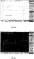
- the following describes measurements of impedances of the first wires 130a conducted in a case (hereinafter referred to as the first experimental example) where the electroconductive member 200 is not attached to the parts of the protruding portions Pa of the first wires 130a of the cable assembly A1, and in a case (hereinafter referred to as the second experimental example) where the electroconductive member 200 is attached to the parts of the protruding portions Pa of the first wires 130a of the cable assembly A1.
- These measurements are made passing differential step pulse signals of a rise time of 200 ps through the first wires 130a.
- Figure 3A shows the measurement result of the first experimental example.
- the parts (intermediate parts) of the protruding portions Pa exhibited impedance of approximately 110.8 ⁇ as indicated by a dashed line.
- Figure 3B shows the measurement result of the second experimental example.
- the parts (intermediate parts) of the protruding portions Pa exhibited impedance of approximately 104.0 ⁇ as indicated by a dashed line. It is thus found that the protruding portions Pa of the first wires 130a is lower in the second experimental example (including the electroconductive member 200) than the first experimental example (not including the electroconductive member 200).
- the cable assembly A1 and its manufacturing method described above provide the following technical features and effects.
- impedance is lowered in the protruding portions Pa of the first wires 130a because of the electroconductive member 200 is wound around the parts of the protruding portions Pa of the first wires 130a. This contributes to matched impedances between the protruding portions Pa of the first wires 130a and the portions of the first wires 130a that are located inside the shield conductor 120 and the outer insulator 110.
- the cable assembly A1 is easy to manufacture for the following reasons. 1)
- the electroconductive member 200 is simply wound around the parts of the protruding portions Pa of the first wires 130a, facilitating attachment of the electroconductive member 200 to the protruding portions Pa of the first wires 130a. Even if the protruding portions Pa of the first wires 130a are spaced from each other, the electroconductive member 200 can be wound around the parts of the protruding portions Pa while bringing the protruding portions Pa closer to each other. 2)
- the electroconductive member 200 can be wound around the parts of the protruding portions Pa of the first wires 130a after connecting the first wires 130a to the terminal 400a and the second wires 130b to the terminals 400b.
- the protruding core wires 132a of the protruding portions Pa can be easily connected to the terminals 400a because this connection work is made before bundling the protruding portions Pa of the first wires 130a with the electroconductive member 200.
- the protruding portions Pa of the first wires 130a are bundled with the electroconductive member 200, facilitating the handling of the bundled protruding portions Pa of the first wires 130a when manufacturing the cable assembly A1.
- the protruding portions Pa of the first wires 130a, the protruding portions Pb of the second wires 130b, the electroconductive member 200, and the first and second connection points are simply housed in the shield case 500.
- the electroconductive member 200 is configured as floating electrically, it is possible to omit the step of electrically connecting the electroconductive member 200.
- the cable assembly A1 has improved electro-magnetic compatibility (EMC) characteristic. This is because the shield case 500 houses the protruding portions Pa of the first wires 130a, the protruding portions Pb of the second wires 130b, the electroconductive member 200, and the first and second connection points.
- EMC electro-magnetic compatibility
- a cable assembly A2 according to the second embodiment of the invention will be hereinafter described with reference to Fig. 4 to Fig. 5B .
- the cable assembly A2 has the same configuration to that of the cable assembly A1, except the following difference.
- the difference is that the electroconductive member 200' has a different configuration from that of the electroconductive member 200.
- the difference will be solely described in detail, without repeating descriptions on the cable assembly A2 that overlap with those of the cable assembly A1.
- Figure 4 shows the Y-Y' and X-X' directions in a similar manner to the assembly A1.
- Fig. 4 shows only part of the cable 100 and shows the shield case 500 in dashed lines.
- the electroconductive member 200' is an electroconductive plate (e.g. a metal plate or a pressed metal plate) or an electroconductive tape (e.g. a copper film tape).
- the electroconductive member 200' has a Y-Y' direction dimension that is smaller than that of the protruding portions Pa of the first wires 130a.
- the electroconductive member 200' in a flat state (unwound state) has such an X-X' direction dimension as to surround and cover the protruding portions Pa of the first wires 130a.
- the electroconductive member 200' has such a Y-Y' direction dimension, an X-X' direction dimension, and a thickness as to achieve matched impedances between the protruding portion Pa of each first wire 130a and the part of each first wire 130a that is located inside the shield conductor 120 and the outer insulator 110.
- the electroconductive member 200' is wound and wrapped around parts in the Y-Y' direction of the protruding portions Pa of the first wires 130a (e.g. intermediate parts in the Y-Y' direction of the protruding portions Pa) such that the distance in the X-X' direction between portions other than distal parts of the protruding portions Pa of the first wires 130a (including parts in the Y-Y' direction of the protruding portion Pa) is smaller than the distance in the X-X' direction between the terminals 400a.
- the distal parts of the protruding portions Pa are the parts on the Y-direction side relative to the parts of the protruding portions Pa around which the electroconductive member 200' is wound.
- the portions other than the distal parts of the protruding portions Pa of the first wires 130a may be in contact with each other or may be arranged with an interval therebetween. Some examples of these arrangements are shown in Fig. 5A and Fig. 5B.
- Fig. 5A shows an aspect of the electroconductive member 200', which is wound around the parts in the Y-Y' direction of the protruding portions Pa of the first wires 130a such that the first end portion 210' and the second end portion 220' of the electroconductive member 200' face each other with a clearance therebetween.
- Fig. 5A shows an aspect of the electroconductive member 200', which is wound around the parts in the Y-Y' direction of the protruding portions Pa of the first wires 130a such that the first end portion 210' and the second end portion 220' of the electroconductive member 200' face each other with a clearance therebetween.
- the electroconductive member 200' is wound around the part in the Y-Y' direction of the protruding portions Pa of the first wires 130a such that the first end portion 210' is in contact with the electroconductive member 200' from inside and the second end portion 220' is in contact with the electroconductive member 200' from outside.
- the electroconductive member 200' is fixed to the parts of the protruding portions Pa of the first wires 130a.
- the fixation of the electroconductive member 200' is achieved by winding the electroconductive member 200', by swaging the electroconductive member 200', using a bonding agent, and/or using an adhesive agent. It should be noted that the electroconductive member 200' is not wound around the protruding portions Pb of the second wires 130b.
- the electroconductive member 200' may be configured to float electrically or to be electrically connected to the shield conductor 120 and/or the shield case 500.
- a method for manufacturing the cable assembly A2 configured as described above is substantially the same as the method for manufacturing the cable assembly A1.
- the difference is that the electroconductive member 200' is wound in different steps from that of the electroconductive member 200 of the first embodiment.
- the following steps of winding the electroconductive member 200' are performed before or after the steps of connecting the first wires 130a to the terminals 400a and connecting the second wires 130b to the terminals 400b.
- the electroconductive member 200' being an electroconductive plate is bent or curved such that the first end portion 210' and the second end portion 220' face each other with a clearance therebetween, and the electroconductive member 200' is wound around only the parts in the Y-Y' direction of the protruding portions Pa of the first wires 130a.
- This winding results in that the distance in the X-X' direction of the portions other than the distal parts of the protruding portions Pa of the first wires 130a is smaller than the distance in the X-X' direction between the terminals 400a.
- the electroconductive member 200' being an electroconductive tape is wound around only the parts in the Y-Y' direction of the protruding portions Pa of the first wires 130a such that the first end portion 210' and the second end portion 220' are in contact with each other.
- This winding results in that the first end portion 210' and the second end portion 220' overlap each other, with the first end portion 210' in contact with the electroconductive member 200' from inside and the second end portion 220' in contact with the electroconductive member 200' from outside, and that the distance in the X-X' direction of the portions other than the distal parts of the protruding portions Pa of the first wires 130a is smaller than the distance in the X-X' direction between the terminals 400.
- the electroconductive member 200' thus wound is fixed only to the parts in the Y-Y' direction of the protruding portion Pa.
- This fixing may be performed through the following procedure, in place of the winding. 1) After or during the winding, the electroconductive member 200' is swaged such that the first and the second end portions 210', 220' extend inward, so that the electroconductive member 200' is fixed only to the parts in the Y-Y' direction of the protruding portion Pa. 2) A bonding agent or an adhesive agent is applied on the electroconductive member 200' as wound and the parts in the Y-Y' direction of the protruding portions Pa, so that the electroconductive member 200' is fixed only to the parts in the Y-Y' direction of the protruding portions Pa.
- the cable assembly A2 and its manufacturing method described above provide technical features and effects similar to those of the cable assembly A1 and its manufacturing method.
- the cable assembly A2 and its manufacturing method further provide the following technical features and effects. Impedance is further lowered in the protruding portions Pa of the first wires 130a because the winding of the electroconductive member 200' results in that the distance in the X-X' direction of the portions other than the distal parts of the protruding portions Pa of the first wires 130a is smaller than the distance in the X-X' direction between the terminals 400a. This further contributes to matched impedances between the protruding portions Pa of the first wires 130a and the portions of the first wires 130a that are located inside the shield conductor 120 and the outer insulator 110.
- the electroconductive member 200' was wound not only around the protruding portions Pa of the first wires 130a but also around the protruding portions Pb of the second wires 130b, it would be difficult to arrange the portions other than the distal parts of the protruding portions Pa of the first wires 130a at a smaller distance therebetween in the X-X' direction than the distance in the X-X' direction between the terminals 400a.
- This is in contrast with the cable assembly A2 with the electroconductive member 200' wound only around the parts of the protruding portions Pa of the first wires 130a. It is therefore easy to arrange the portions other than the distal parts of the protruding portions Pa of the first wires 130a at a smaller distance therebetween in the X-X' direction than the distance in the X-X' direction between the terminals 400a.
- a cable assembly A3 according to the third embodiment of the invention will be hereinafter described with reference to Fig. 6A through Fig. 7 .
- the cable assembly A3 has the same configuration to that of the cable assembly A1, except the following differences.
- the first difference is that the body 300' has a different configuration from that of the body 300 of the second embodiment.
- the second difference is that the layout of the terminals 400b and the second wires 130b is different between the second and third embodiments.
- the third difference is that the electroconductive member 200 is replaced with the electroconductive member 200'.
- the fourth difference is that the shield case 500' has a different shape from that of the shield case 500 of the first embodiment.
- the body 300' is a block of insulating resin.
- the body 300' is smaller in the X-X' direction than the body 300.
- the body 300' is larger in the Z-Z' direction than the body 300. In other words, the body 300' is elongated in the Y-Y' direction.
- the body 300' holds the terminals 400a with a clearance therebetween in the X-X' direction.
- the body 300' holds the terminals 400b with a clearance therebetween in the X-X' direction, on the Z'-direction side (one side in the third direction) relative to the terminal 400a.
- the terminals 400a and the terminals 400b may be insert-molded in the body 300' or securely press-fitted in holes or grooves in the body 300'.
- the end portions of the core wires 132b of the protruding portions Pb of the second wires 130b are connected to the terminals 400b by soldering or other means. Accordingly, as shown in Fig. 6B and Fig. 7 , the protruding portions Pb of the second wires 130b are located on the Z'-direction side (one side in the third direction) relative to the protruding portions Pa of the first wires 130a.
- Fig. 6A and Fig. 6B show only part of the cable 100.
- the electroconductive member 200' is configured as described for the second embodiment.
- the shield case 500' has the same configuration as the shield case 500 of the first embodiment, except that the shield case 500' is a metal rectangular tube.
- Fig. 6A and Fig. 6B show the shield case 500' in dashed line for the convenience of explanation.
- a method for manufacturing the cable assembly A3 configured as described above is substantially the same as the method for manufacturing the cable assembly A1.
- the differences are that the step of connecting the second wires 130b is different between the first and third embodiments, and that the steps of winding the electroconductive member 200' are different from that of the electroconductive member 200 of the first embodiment.
- the steps of connecting the second wires 130b and winding the electroconductive member 200' are different from that of the electroconductive member 200 of the first embodiment.
- the protruding core wires 132b of the protruding portions Pb of the second wires 130b of the cable 100 are connected to the respective terminals 400b by soldering or other means.
- the protruding portions Pb of the second wires 130b are thus located on the Z'-direction side relative to the protruding portions Pa of the first wires 130a.
- the steps of winding the electroconductive member 200' is performed, in a similar manner to the second embodiment, before or after the steps of connecting the first wires 130a to the terminals 400a and the second wires 130b to the terminals 400b.
- the protruding portions Pb of the second wires 130b located on the Z'-direction side relative to the protruding portions Pa of the first wires 130a, is not likely to obstruct the winding of the electroconductive member 200'.
- the cable assembly A3 and its manufacturing method described above provide technical features and effects similar to those of the cable assembly A2 and its manufacturing method.
- the first connecting member of the invention may be modified in any manner as long as it is electrically conductive and connectable to the core wires of the first wires of the embodiments described above or of the modifications described below.
- the second connecting member of the invention may be modified in any manner as long as it is electrically conductive and connectable to the core wire of the second wire of the embodiments described above or of the modifications described below.
- the body 300, the terminals 400a, and the terminals 400b may be replaced with a circuit board 600 as in a cable assembly A1' as shown in Fig. 8 .
- the cable assembly A1' has the same configuration as the cable assembly A1, except that the body 300, the terminal 400a and the terminal 400b are replaced with the circuit board 600.
- On the Z-direction-side face of the circuit board 600 there are arranged electrodes 610b, 610a, 610a, 610b, in this order, in the X-X' direction with intervals therebetween.
- the electrodes 610a are respectively connected to the protruding core wires 132a of the protruding portions Pa of the first wires 130a.
- the electrodes 610b are respectively connected to the protruding core wires 132b of the protruding portions Pb of the second wires 130b. Each electrode 610a corresponds to the first connecting member described above, and each electrode 610b corresponds to the second connecting member described above. Also in the cable assembly A2, the circuit board 600 may be provided in place of the body 300, the terminal 400a and the terminal 400b. In Fig. 8 , the electrodes 620a are arranged on the Z-direction-side face of the circuit board 600 and contactable with signal transmission terminals of a connection target as described above, and the electrodes 620b are arranged on the Z-direction-side face of the circuit board 600 and contactable with other terminals of the connection target. The electrodes 610a are connected to the electrodes 620a via electroconductive lines (not shown) in the circuit board 600. The electrodes 610b are connected to the electrode 620b via electroconductive lines (not shown) in the circuit board 600.
- the body 300', the terminal 400a, and the terminal 400b may be replaced with a circuit board 600' as in a cable assembly A3' as shown in Fig. 9 .
- the cable assembly A3' has the same configuration as the cable assembly A3, except that the body 300', the terminal 400a and the terminal 400b are replaced with the circuit board 600'.
- On the Z-direction-side face of the circuit board 600' there are arranged electrodes 610a' in the X-X' direction with an interval therebetween.
- electrodes 610b' On the Z'-direction-side face of the circuit board 600', there are arranged electrodes 610b' in the X-X' direction with an interval therebetween.
- the electrodes 610a' are respectively connected to the protruding core wires 132a of the protruding portions Pa of the first wires 130a.
- the electrodes 610b' are respectively connected to the protruding core wires 132b of the protruding portions Pb of the second wires 130b.
- Each electrode 610a' corresponds to the first connecting member described above, and each electrode 610b' corresponds to the second connecting member described above.
- the electrodes 620a' are arranged on the Z-direction-side face of the circuit board 600 and contactable with signal transmission terminals of a connection target as described above, and the electrodes 620b' are arranged on the Z'-direction-side face of the circuit board 600 and contactable with other terminals of the connection target.
- the electrodes 610a' are connected to the electrodes 620a' via electroconductive lines (not shown) in the circuit board 600'.
- the electrodes 610b' are connected to the electrode 620b' via electroconductive lines (not shown) in the circuit board 600'.
- each terminal of any aspect described above may not protrude from the body but may be housed in a groove or hole in the body. In this case, the contact portion of each terminal is to be brought into contact with each terminal of a mating connector received in the groove or the hole of the body. It is should be noted that there is provided at least one first connecting member of any aspect described above and at least one second connecting member of any aspect described above. The at least one second connecting member may be omitted.
- the cable of the invention includes at least one first wire, which may be modified in any manner as long it is a signal wire inside the outer insulator and the shield conductor of the cable and includes a protruding portion protruding substantially in the first direction from the outer insulator and the shield conductor, with the core wire of the protruding portion connected to the first connecting member of any aspect described above.
- the first direction is the longitudinal direction of the cable.
- the first wire of the cable of the invention may be configured for transmission of signals other than differential signals.
- the cable of the invention may include at least one second wire, which may be modified in any manner as long it is a wire other than a signal wire, disposed inside the outer insulator and the shield conductor of the cable and includes the protruding portion protruding substantially in the first direction from the outer insulator and the shield conductor, with the core wire of the protruding portion connected to the second connecting member of any aspect described above.
- the at least one second wire of the cable of the invention may be omitted.
- the at least one second wire and the terminal connected thereto may be omitted as in a cable assembly A1" shown in Fig. 10 . Except this omission, the cable assembly A1" has the same configuration as the cable assembly A1.
- the cable assemblies A2 and A3 may also be so modified to omit the second wire and the terminal connected thereto.
- the second wire and the electrode connected thereto are omitted also in a cable assembly A1'" as shown in Fig. 11 .
- the second wire and the electrode connected thereto may be omitted also in the cable assembly A2 including the circuit board 600 in place of the body 300, the terminal 400a and the terminal 400b, and in the cable assembly A3'.
- the electroconductive member of the invention may be modified in any manner as long as it is an electroconductive plate or electroconductive tape wound around the at least a part in the first direction of the protruding portion of the first wire of any aspect described above.
- the electroconductive member may cover the inner insulator in entirety in the first direction of the protruding portion of the first wire.
- the electroconductive member may be wound around the at least parts of the protruding portions of a pair of first wires such that the distance in the second direction between the parts of the protruding portions of the first wires is smaller than the distance in the second direction between the first connecting members. The second direction crosses the first direction.
- the electroconductive tape or electroconductive plate of any aspect described above may be wound around the at least the part(s) in the first direction of the protruding portion(s) of the first wire(s) of any embodiment described above such that the first and second end portions of the electroconductive tape or electroconductive plate face each other with a clearance therebetween.
- the electroconductive plate or electroconductive tape of any aspect described above may be wound around the at least part(s) in the first direction of the protruding portion(s) of the first wire(s) of any embodiment described above described above such that one of the first and second end portions of the electroconductive plate or electroconductive tape is in contact with the electroconductive plate or electroconductive tape.
- the electroconductive plate or electroconductive tape of any aspect described above may be wound around the at least part(s) in the first direction of the protruding portion(s) of the first wire(s) of any aspect described above such that the first and second end portions of the electroconductive plate or electroconductive tape are in contact with each other at their distal ends.
- the electroconductive plate or electroconductive tape of any aspect described above may be wound in a plurality of turns around the at least part(s) in the first direction of the protruding portion(s) of the first wire(s) of any aspect described above, so that the first end portion of the electroconductive plate or electroconductive tape is in contact with the electroconductive plate or electroconductive tape from inside, and the second end portion, opposite to the first end portion, of the electroconductive plate or electroconductive tape is in contact with the electroconductive plate or electroconductive tape from outside.
- the electroconductive member of any aspect described above may be wound around the at least parts in the first direction of the protruding portions of the first and second wires of any aspect described above.
- the electroconductive member of any aspect described above may be fixed to the at least part(s) in the first direction of the protruding portion(s) of the first wire(s) of any embodiment described above.
- the swaging of the electroconductive member of any aspect described above may be performed by deforming at least a portion of the electroconductive member is to the inside and fixing the portion to the at least part(s) in the first direction of the protruding portion(s) of the first wire(s) of any aspect described above.
- the shield case of the invention may be modified in any manner as long as it is configured to at least cover the protruding portion(s) of the first wire(s), the electroconductive member, and the or each connection point at which the or each core wire of the protruding portion is connected to the or each first connecting member.
- the shield case of the invention may be configured to cover, in addition to the protruding portion(s) of the first wire(s), the electroconductive member, and the or each connection point at which the or each core wire of the protruding portion is connected to the or each first connecting member, at least part of the body or at least part the circuit board.
- the shield case of any aspect described above may be an insulating resin tube having an inner surface with a deposited metal film or the like.
- the shield case of any aspect described above may be shaped generally like a half tube covering the protruding portion(s) of the first wire(s), the electroconductive member, and the or each connection point at which the or each core wire of the protruding portion is connected to the or each first connecting member, from one of sides in the third direction crossing the first direction and the second direction.
- the shield case of the invention may be omitted.
- a plastic molding there may be insert-molded the protruding portion(s) of the first wire(s), the electroconductive member, and the or each connection point at which the or each core wire of the protruding portion is connected to the or each first connecting member.
- the plastic molding may hold the body or the circuit board.
- the shield case may be omitted.
- the shield case of the invention may be configured to cover the plastic molding in order to at least cover the protruding portion(s) of the first wire(s), the electroconductive member, and the or each connection point at which the or each core wire of the protruding portion is connected to the or each first connecting member.
- the method for manufacturing the cable assembly of the invention may be modified in any manner as long as the method includes cutting away the end portion of the outer insulator and the end portion of the shield conductor inside the outer insulator of the cable so as to protrude the end portion of the at least one first wire in the first direction from the shield conductor and the outer insulator, wherein the first direction being the longitudinal direction of the cable, winding the electroconductive plate or electroconductive tape around the at least part of the end portion of the first wire, and connecting the core wire of the end portion of the first wire to the terminal or to the electrode of the circuit board before or after winding the electroconductive plate or electroconductive tape.
- the core wire of the protruding portion of the or each first wire is connected to an associated electrode (e.g. the electrodes 610a, 610a') of the circuit board and the core wire of the protruding portion of the or each second wire is connected to another electrode (for example, the electrodes 610b, 610b') of the circuit board.
- an associated electrode e.g. the electrodes 610a, 610a'
- another electrode for example, the electrodes 610b, 610b'
- the step of winding the electroconductive member of any aspect described above may include winding the electroconductive member around at least parts of the first and second wires.
- the first direction of the invention may be defined in any manner as long as it is to the longitudinal direction of the cable.
- the second direction of the invention may be defined in any manner as long as it crosses the first direction.
- the third direction of the invention may be defined in any manner as long as it crosses the first and second directions and does not exist on the same plane formed by the first direction and the second direction.
Abstract
Description
- The invention relates to cable assemblies and methods for manufacturing the cable assemblies.
- A common composite cable has a tuboid outer insulator, a shield conductor inside the outer insulator, and a plurality of signal wires inside the shield conductor. Before connecting the core wires of the signal wires of the composite cable to respective terminals of a connector or other device, an end portion of the outer insulator and an end portion of the shield conductor of the composite cable are cut away such that an end portion of the signal wire protrudes from the outer insulator and the shield conductor. The protruding end portion of each signal wire has a higher impedance than that of a portion of the signal wire that is located inside the shield conductor and the outer insulator (hereinafter referred to as an inner portion). In other words, there is an impedance mismatch in each signal wire between its end portion and the inner portion.
-
Patent Literature 1 identified below discloses a first cable assembly which may resolve impedance mismatch in a signal wire as described above.Patent Literature 2 identified below discloses a second cable assembly which may resolve impedance mismatch in a signal wire as described above. The first cable assembly includes a composite cable, a circuit board, a heat-shrinkable tube being an insulator. The composite cable includes two signal wires for differential transmission, a drain wire, and a shield conductor. The signal and drain wires are disposed inside the tuboid shield conductor. A lengthwise end portion of the shield conductor is cut away such as to protrude end portions of the signal wires and the drain wire from the shield conductor. The protruding end portions of the signal and drain wires are respectively connected to electrodes on the circuit board. The protruding end portions of the signal and drain wires, excluding tip portions of the end portions, are received in and covered with the heat-shrinkable tube. - The second cable assembly includes a composite cable, a connector, and a bilayer heat-shrinkable tube. The composite cable includes two signal wires for differential transmission, a drain wire, a shield conductor, and an outer insulator. The tuboid shield conductor is disposed inside the tuboid outer insulator. The signal and drain wires are disposed inside the shield conductor. Lengthwise end portions of the shield conductor and the outer insulator are cut away such as to protrude end portions of the signal and drain wires from the shield conductor and the outer insulator. The protruding end portions of the signal and drain wires are respectively connected to terminals of the connector. The end portions of the signal and drain wires are received in and covered with the tuboid bilayer heat-shrinkable tube. The inner layer of the bilayer heat-shrinkable tube is an electroconductive layer, and the outer layer is an insulator.
-
- Patent Literature 1: Japanese Unexamined Patent Application Publication No.
2002-135938 - Patent Literature 2: Japanese Unexamined Patent Application Publication No.
2005-38617 - As described above, the protruding end portions of the signal and drain wires are covered with the heat-shrinkable tube, which suppresses impedance increases at the end portions of the signal and drain wires to match between the end portions and other portions. However, it takes time and effort to fix the heat-shrinkable tube over the end portions of the signal and drain wires. This is because of requirement to heat and shrink with the heat the heat-shrinkable tube after inserting the end portions of the signal and drain wires into the heat-shrinkable tube.
- The invention is devised in view of the above circumstances to provide a cable assembly with reduced characteristic impedance at a protruding end portion of a first wire of a cable and configured for easy manufacture, and to provide a method for manufacturing the cable assembly.
- To solve the above problem, a cable assembly of the invention includes a first connecting member having electrical conductivity, a cable, and an electroconductive member. The cable includes an outer insulator, a shield conductor disposed inside the outer insulator, and at least one first wire. The first wire is a signal wire disposed inside the shield conductor. The first wire includes a protruding portion protruding substantially in a first direction from the shield conductor and the outer insulator. A core wire of the protruding portion is connected to the first connecting member. The first direction is the longitudinal direction of the cable. The electroconductive member is an electroconductive plate or electroconductive tape wound around at least a part in the first direction of the protruding portion.
- The cable assembly of this aspect provides the following technical features and effects. Firstly, impedance is lowered in the protruding portion of the first wire because of the electroconductive member is wound around at least the part of the protruding portion of the first wire. This contributes to matched impedances between the protruding portion of the first wire and the portion of the first wire located inside the shield conductor and the outer insulator. Secondly, the cable assembly is easy to manufacture. This is because the electroconductive member provided as the electroconductive plate or electroconductive tape is simply wound around at least the part of the protruding portion, thereby greatly facilitating attachment of the electroconductive member to the protruding portion.
- A pair of the first connecting members may be provided. The cable may include a pair of first wires. The electroconductive member may be wound around at least the parts of the protruding portions of the first wires. The cable assembly of this aspect is more easily manufacturable. Even if the protruding portions of the first wires are spaced from each other, the electroconductive member can be wound around the at least parts of the protruding portions while bringing the protruding portions closer to each other.
- The first connecting members may be spaced apart from each other in a second direction, the second direction crossing the first direction. The first wires may be configured to transmit a differential signal. The electroconductive member may be wound around at least the parts of the protruding portions of the first wires such that a distance in the second direction between the parts of the protruding portions of the first wires is smaller than a distance in the second direction between the first connecting members.
- In the cable assembly of this aspect, impedance is further lowered in the protruding portion because the distance in the second direction between the parts of the protruding portions of the first wires is smaller than the distance in the second direction between the first connecting members. This contributes to matched impedances between the protruding portions of the first wires and the portions of the first wires located inside the shield conductor and the outer insulator.
- The electroconductive member may include a first end portion and a second end portion opposite to the first end portion. The electroconductive member may be wound around the at least part of the protruding portion such that at least one of the first and second end portions is in contact with the electroconductive member. In the cable assembly of this aspect, it is easy to wind the electroconductive member around the protruding portion. This is because it is desirable to wind the electroconductive member around the at least part of the protruding portion such that at least one of the first and second end portions is in contact with the electroconductive member.
- Alternatively, the electroconductive member may be wound around the at least part of the protruding portion such that the first end portion and the second end portion face each other with a clearance therebetween. In the cable assembly of this aspect, it is easy to wind the electroconductive member around the protruding portion. This is because it is desirable to wind the electroconductive member around the at least part of the protruding portion such that the first end portion and the second end portion face each other with a clearance therebetween.
- The electroconductive member may float electrically. The cable assembly of this aspect is more easily manufacturable. This is because there is no need to electrically connect the electroconductive member to other component.
- The electroconductive member may be electrically connected to the shield conductor of the cable. In the cable assembly of this aspect, the electroconductive member can be easily grounded through the shield conductor.
- The cable assembly of any aspect described above may further include a shield case at least covering the protruding portion of the first wire, the electroconductive member, and a connection point at which the core wire of the protruding portion is connected to the first connecting member.
- The electroconductive member may be electrically connected to the shield case. In the cable assembly of this aspect, the electroconductive member can be easily grounded through the shield case.
- The cable assembly of any aspect described above may further include a second connecting member having electrical conductivity. The cable may further include a second wire inside the shield conductor. The second wire may be other than a signal wire and include a protruding portion. The protruding portion of the second wire may protrude in the first direction from the shield conductor and the outer insulator. A core wire of the protruding portion of the second wire may be connected to the second connecting member. The electroconductive member may be wound only around the at least parts of the protruding portions of the first wires.
- The second connecting member may be disposed on one side in a third direction relative to the first connecting members, the third direction crossing the first and second directions. The protruding portion of the second wire may be disposed on the one side in the third direction relative to the protruding portions of the first wires. The cable assembly of this aspect is more easily manufacturable for the following reason. As the second connecting member and the protruding portion of the second wire are located on the one side in the third direction relative to the first connecting members and the protruding portions of the first wires, the second wire is not likely to obstruct the winding of the electroconductive member around the at least part of the protruding portion of the first wires.
- The cable assembly of any aspect described above may further include an insulating body holding the first and second connecting members. In this case, the first and second connecting members may be terminals. The body may be replaced with a circuit board. In this case, the first and second connecting members may not be terminals but electrodes on the circuit board.
- A method for manufacturing a cable assembly of the invention includes cutting away an end portion of an outer insulator and an end portion of a shield conductor inside the outer insulator of a cable so as to protrude an end portion of a first wire in a first direction from the shield conductor and the outer insulator, the first wire being a signal wire, the first direction being a longitudinal direction of the cable; connecting a core wire of the end portion of the first wire to a terminal or to an electrode of a circuit board; and winding an electroconductive plate or electroconductive tape around at least a part in the first direction of the end portion of the first wire after the connection of the core wire of the first wire. It should be noted that the winding of electroconductive plate or electroconductive tape may be performed before the connection of the core wire of the first wire.
- The method for manufacturing the cable assembly of this aspect provides the following technical features and effects. Firstly, it is possible to lower the impedance in the end portion of the first wire simply by winding the electroconductive plate or electroconductive tape around at least the part of the end portion of the first wire. This contributes to matched impedances between the end portion of the first wire and the portion of the first wire located inside the shield conductor and the outer insulator. Secondly, the method contributes to easy manufacture of the cable assembly. This is because the electroconductive plate or electroconductive tape is simply wound around at least the part of the end portion of the first wire, greatly facilitating attachment of the electroconductive plate or electroconductive tape to the end portion of the first wire.
- A pair of first wires may be provided. A pair of the terminals or a pair of the electrodes of the circuit board may be provided. The connection of the core wire of the first wire may include connecting the core wires of the end portions of the first wires respectively to the terminals or to the electrodes of the circuit board. The winding of the electroconductive plate or electroconductive tape may include winding the electroconductive plate or electroconductive tape around the at least parts of the end portions of the first wires.
- The manufacturing method of this aspect further contributes to easy manufacture of the cable assembly. Even if the protruding portions of the first wires are spaced from each other, the electroconductive member can be wound around the at least parts of the protruding portions while bringing the protruding portions closer to each other.
- The terminals or the electrodes of the circuit board may be spaced apart from each other in a second direction, the second direction crossing the first direction. The winding of the electroconductive plate or electroconductive tape may include winding the electroconductive plate or electroconductive tape around the at least parts of the end portions of the first wires such that a distance in the second direction between the parts of the end portions of the first wires is smaller than a distance in the second direction between the terminals or electrodes.
- In the manufacturing method of this aspect, impedance is further to lowered in the end portions of the first wires because the distance in the second direction between the parts of the end portions of the first wires is smaller than the distance in the second direction between the terminals or electrodes. This further contributes to matched impedances between the end portions of the first wires and the portions of the first wires located inside the shield conductor and the outer insulator.
- The electroconductive plate or electroconductive tape may include a first end portion and a second end portion opposite to the first end portion. The winding of the electroconductive plate or electroconductive tape may include winding the electroconductive plate or electroconductive tape around the at least part of the end portion of the first wire such that at least one of the first end portion and the second end portion is in contact with the electroconductive plate or electroconductive tape, or alternatively such that the first end portion and the second end portion face each other with a clearance therebetween.
- The manufacturing method of these aspects facilitates the winding of the electroconductive plate or electroconductive tape around the protruding portion. This is because it is desirable to wind the electroconductive plate or electroconductive tape around the at least part of the protruding portion such that one of one of the first and second end portions of the electroconductive plate or electroconductive tape is in contact with the electroconductive plate or electroconductive tape, or alternatively such that the first and second end portions of the electroconductive plate or electroconductive tape face each other with a clearance therebetween.
- The manufacturing method of any aspect described above may further include bringing the electroconductive plate or electroconductive tape into electrical connection with the shield conductor of the cable. In the manufacturing method of this aspect, the electroconductive plate or electroconductive tape can be easily grounded through the shield conductor.
- The manufacturing method of any aspect described above may further include placing a shield case such as to at least cover the end portion of the first wire, the electroconductive plate or electroconductive tape, and a connection point at which the core wire of the end portion of the first wire is connected to the terminal or to the electrode of the circuit board.
- The manufacturing method may further include bringing the shield case into electrical connection with the electroconductive plate or electroconductive tape. In the manufacturing method of this aspect, the electroconductive plate or electroconductive tape can be easily grounded through the shield case.
- The cable may further include a second wire inside the shield conductor, the second wire not being a signal wire and including a protruding portion. The cutting of the outer insulator and the shield conductor of the cable may include protruding the end portion of the first wire and an end portion of the second wire in the first direction of the cable from the shield conductor and the outer insulator. The connection of the core wire of the first wire may include connecting a core wire of the end portion of the second wire to another terminal or to another electrode of the circuit board. The winding of the electroconductive plate or electroconductive tape may include winding the electroconductive plate or electroconductive tape only around the at least part of the end portion of the first wire.
- In the manufacturing method of this aspect, the electroconductive plate or electroconductive tape is simply wound only around the end portion of the first wire, thereby greatly facilitating attachment of the electroconductive plate or electroconductive tape to the end portion of the first wire.
-
-
Fig. 1A is a schematic plan view of a cable assembly according to the first embodiment of the invention, with a shield case shown as transparent. -
Fig. 1B is a schematic side view of the cable assembly, with the shield case shown as transparent. -
Fig. 2A is an end view of the cable assembly including an aspect of the electroconductive member, taken alongline 2A-2A inFig. 1A . -
Fig. 2B is an end view of the cable assembly including another aspect of the electroconductive member, taken alongline 2A-2A inFig. 1A . -
Fig. 3A is a graph showing characteristic impedance of a pair of first wires of a cable assembly, not including an electroconductive member, according to the first experimental example. -
Fig. 3B is a graph showing characteristic impedance of a pair of first wires of a cable assembly, including an electroconductive member, according to the second experimental example. -
Fig. 4 is a schematic plan view of a cable assembly according to the second embodiment of the invention, with a shield case shown as transparent. -
Fig. 5A is an end view of the cable assembly including an aspect of the electroconductive member, taken alongline 5A-5A inFig. 4 . -
Fig. 5B is an end view of the cable assembly including another aspect of the electroconductive member, taken alongline 5A-5A inFig. 4 . -
Fig. 6A is a schematic plan view of a cable assembly according to the third embodiment of the invention, with a shield case shown as transparent. -
Fig. 6B is a schematic side view of the cable assembly, with the shield case shown as transparent. -
Fig. 7 is an end view of the cable assembly including an aspect of an electroconductive member, taken along line 7-7 inFig. 6A . -
Fig. 8 is a schematic plan view of a cable assembly according to a first modification of the first embodiment, with the shield case shown as transparent. -
Fig. 9 is a schematic plan view of a cable assembly according to a first modification of the third embodiment, with the shield case shown as transparent. -
Fig. 10 is a schematic plan view of a cable assembly according to a second modification of the first embodiment, with the shield case shown as transparent. -
Fig. 11 is a schematic plan view of a cable assembly according to a third modification of the first embodiment, with the shield case shown as transparent. - The first to third embodiments of the invention will be described hereinafter.
- A cable assembly A1 according to the first embodiment of the invention will be hereinafter described with reference to
Fig. 1A to Fig. 3B . The cable assembly A1 includes acable 100, anelectroconductive member 200, abody 300, a pair ofterminals 400a (first connecting member), a pair ofterminals 400b (second connecting member), and ashield case 500. These components of the cable assembly A1 will be described in detail. It should be noted that the Y-Y' direction shown inFig. 1A andFig. 1B corresponds to the longitudinal direction of thecable 100 and also corresponds to the first direction in the claims. The X-X' direction shown inFig. 1A corresponds to the array direction of theterminals Fig. 1B corresponds to the third direction in the claims. The Z-Z' direction orthogonally crosses the Y-Y' and X-X' directions. - As shown in
Fig. 1A andFig. 1B , thecable 100 includes anouter insulator 110, ashield conductor 120, a pair offirst wires 130a, and a pair ofsecond wires 130b.Fig. 1A andFig. 1B show only part of thecable 100. - The
outer insulator 110 is a tuboid sheath. Theshield conductor 120 is a tuboid braided conductive wires or a spirally wound tape made of metal film, and theshield conductor 120 is disposed inside theouter insulator 110. Thefirst wires 130a and thesecond wires 130b are disposed inside theshield conductor 120. Theouter insulator 110 and theshield conductor 120 are cut away at their Y-direction end portions. Accordingly, the Y-direction end portions (hereinafter referred to as protruding portions Pa) of thefirst wires 130a and the Y-direction end portions (hereinafter referred to as protruding portions Pb) of thesecond wires 130b protrude in the Y direction from theouter insulator 110 and theshield conductor 120. - The
first wires 130a are signal wires forming a differential pair for transmission of high frequency signals (differential signals). Thefirst wires 130a each include aninner insulator 131a and acore wire 132a. Eachcore wire 132a is disposed inside each tuboidinner insulator 131 a as shown inFig. 2A and Fig. 2B . As shown inFig. 1A andFig. 1B , the protruding portion Pa of eachfirst wire 130a is configured such that the Y-direction end portion of theinner insulator 131a is cut away to protrude the Y-direction end portion of thecore wire 132a. - The
second wire 130b may each be a wire other than a signal wire (e.g. a power wire, a ground wire, and/or a drain wire) and/or a low speed signal wire (e.g. a signal wire for transmission of signals of lower speed than the aforementioned high frequency signals). Eachsecond wire 130b includes aninner insulator 131b and acore wire 132b. As shown inFig. 2A and Fig. 2B , thecore wire 132b is disposed inside the tuboidinner insulator 131b. As shown inFig. 1A andFig. 1B , the protruding portion Pb of thesecond wire 130b is configured such that the Y-direction end portion of theinner insulator 131b is cut away to protrude the Y-direction end portion of thecore wire 132b. - As shown in
Fig. 1A andFig. 1B , thebody 300 is a block of insulating resin. Thebody 300 holds theterminals terminals body 300 or securely press-fitted in holes or grooves in thebody 300. - The pair of the
terminals 400a forms a differential pair for transmission of high frequency signals (differential signals). Each terminal 400a includes acontact portion 410a and atail 420a. Thecontact portion 410a is the Y-direction end portion of the terminal 400a and protrudes from thebody 300 in the Y direction. Thecontact portion 410a is contactable with a signal transmission terminal of a connection target (not shown), such as a mating connector, for connection with the cable assembly A1. Eachtail 420a is the Y'-direction end portion of the terminal 400a and protrudes from thebody 300 in the Y' direction. Eachtail 420a is connected to the end portion of thecore wire 132a of the protruding portion Pa of the associatefirst wire 130a by soldering or other means. - The
terminals 400b are each a terminal other than a signal terminal (e.g. a power terminal, a ground terminal, and/or a drain terminal) and/or a low speed signal terminal (e.g. a signal terminal for transmission of signals of lower speed than the aforementioned high frequency signals). Each terminal 400b includes acontact portion 410b and atail 420b. Thecontact portion 410b is the Y-direction end portion of the terminal 400b and protrudes from thebody 300 in the Y direction. Thecontact portions 410b are contactable with other terminals of the connection target. Eachtail 420b is the Y'-direction end portion of the terminal 400b and protrudes from thebody 300 in the Y' direction. Eachtail 420b is connected to the end portion of thecore wire 132b of the protruding portion Pb of the correspondingsecond wire 130b by soldering or other means. - The
electroconductive member 200 is an electroconductive plate (e.g. a metal plate or a pressed metal plate) or an electroconductive tape (e.g. a copper film tape). Theelectroconductive member 200 in a flat state (unwound state) has a Y-Y' direction dimension that is smaller than that of the protruding portions Pa of thefirst wires 130a. Theelectroconductive member 200 has such an X-X' direction dimension as to surround and cover the protruding portions Pa of thefirst wires 130a. It is preferable that theelectroconductive member 200 has such a Y-Y' direction dimension, an X-X' direction dimension, and a thickness as to achieve matched impedances between the protruding portion Pa of eachfirst wire 130a and the part of eachfirst wire 130a that is located inside theshield conductor 120 and theouter insulator 110. - The
electroconductive member 200 includes afirst end portion 210 and asecond end portion 220. Thesecond end portion 220 is provided at an opposite side from thefirst end portion 210. Theelectroconductive member 200 is wound and wrapped around parts in the Y-Y' direction of the protruding portions Pa of thefirst wires 130a (e.g. intermediate parts in the Y-Y' direction of the protruding portions Pa). For example,Fig. 2A shows an aspect of the electroconductivemember 200, which is wound around the parts in the Y-Y' direction of the protruding portions Pa of thefirst wires 130a such that thefirst end portion 210 and thesecond end portion 220 face each other with a clearance therebetween.Fig. 2B shows another aspect of the electroconductivemember 200, which is wound around the parts in the Y-Y' direction of the protruding portions Pa of thefirst wires 130a such that thefirst end portion 210 is in contact with theelectroconductive member 200 from inside and thesecond end portion 220 is in contact with theelectroconductive member 200 from outside. In either of these aspects, theelectroconductive member 200 is fixed to the parts of the protruding portions Pa of thefirst wires 130a. The fixation of the electroconductivemember 200 is achieved by winding theelectroconductive member 200, by swaging theelectroconductive member 200, using a bonding agent, and/or using an adhesive agent. It should be noted that theelectroconductive member 200 is not wound around the protruding portions Pb of thesecond wires 130b. - The
electroconductive member 200 may be configured such as to (1) float electrically or (2) be electrically connected to theshield conductor 120 and/or theshield case 500. Theelectroconductive member 200 in configuration (1) is not in contact or electrical connection with theshield conductor 120 of thecable 100 and/or theshield case 500. Theelectroconductive member 200 in configuration (2) may be (2a) in direct contact and electrical connection with theshield conductor 120 and/or theshield case 500 or (2b) in electrical connection with theshield conductor 120 and/or theshield case 500 by connection means (not shown), such as a pin, solder, an electroconductive bonding agent, and a lead wire. In either of configurations (2a) and (2b), theelectroconductive member 200 is grounded through theshield conductor 120 and/or theshield case 500. - As shown in
Fig. 1A andFig. 1B , theshield case 500 is a metal tube and has openings that respectively open in the Y and Y' directions. Theshield case 500 houses (covers) at least the protruding portions Pa of thefirst wires 130a, the protruding portions Pb of thesecond wires 130b, theelectroconductive member 200, a plurality of first connection points, and a plurality of second connection points. The first connection points are points at which thetails 420a of theterminals 400a are connected to thecore wires 132a of the protruding portions Pa of thefirst wires 130a. The second connection points are points at which thetails 420b of theterminals 400b are connected to thecore wires 132b of the protruding portions Pb of thesecond wires 130b. Thebody 300 is located outside of theshield case 500, particularly on the side of the Y-direction-side opening of theshield case 500. Thecable 100 is led through the Y'-direction-side opening of theshield case 500 to the outside of theshield case 500.Fig. 1A andFig. 1B show theshield case 500 in dashed lines for the convenience of explanation. - The
shield case 500 can be composed of two or more pieces that may be removably assembled together in the X-X' or Z-Z' direction. Theshield case 500 may preferably connected electrically to, but not limited thereto, theshield conductor 120 of thecable 100 by direct contact or via other connection means (not shown, such as a pin, solder, an electroconductive bonding agent, and a lead wire). Theshield case 500 may be grounded by contacting a shield case of the aforementioned connection target. - A method for manufacturing the cable assembly A1 configured as described above will be hereinafter described. The
cable 100 is prepared. The Y-direction end portion of theouter insulator 110 and the end portion of theshield conductor 120 of thecable 100 are cut away so as to protrude the Y-direction end portions of thefirst wires 130a and the Y-direction end portions of thesecond wires 130b from theouter insulator 110 and theshield conductor 120. The Y-direction end portions of thefirst wires 130a form the protruding portions Pa, and the Y-direction end portions of thesecond wires 130b form the protruding portions Pb. The Y-direction end portions of theinner insulators 131a of the protruding portions Pa are cut away so as to protrude the Y-direction end portions of thecore wires 132a protrude from theinner insulators 131a. The Y-direction end portions of theinner insulators 131b of the protruding portions Pb are cut away so as to protrude the Y-direction end portions of thecore wires 132b from theinner insulators 131b. - The
body 300, theterminals 400a and theterminals 400b are prepared. The body already holds theterminals core wires 132a of the protruding portions Pa of thefirst wires 130a are connected to therespective terminals 400a by soldering or other means, and these connection points form the first connection points. The protrudingcore wires 132b of the protruding portions Pb of thesecond wires 130b are connected to the associatedterminals 400b by soldering or other means, and these connection points form the second connection points. - Then the
electroconductive member 200 is prepared. Theelectroconductive member 200 is wound around and fixed to parts in the Y-Y' direction of the protruding portions Pa of thefirst wires 130a. Specifically, one of the following procedures 1) or 2) is adopted. 1) Theelectroconductive member 200 being an electroconductive plate is bent or curved such that thefirst end portion 210 and thesecond end portion 220 face each other with a clearance therebetween, and theelectroconductive member 200 is wound around only the parts in the Y-Y' direction of the protruding portions Pa of the first wires 130a. 2) Theelectroconductive member 200 being an electroconductive tape is wound around only the parts in the Y-Y' direction of the protruding portions Pa of thefirst wires 130a such that thefirst end portion 210 and thesecond end portion 220 overlap with each other. In the procedure 2), thefirst end portion 210 is brought into contact with theelectroconductive member 200 from inside, and thesecond end portion 220 is brought into contact with theelectroconductive member 200 from outside. In either procedure 1) or 2), theelectroconductive member 200 is fixed only to the parts in the Y-Y' direction of the protruding portions Pa. This fixing may be performed through the following procedures, in place of the winding. 3) After or during the winding, theelectroconductive member 200 is swaged such that the first and thesecond end portions electroconductive member 200 is fixed only to the portions in the Y-Y' direction of the protruding portion Pa. 4) A bonding agent or an adhesive agent is applied on theelectroconductive member 200 as wound and the parts in the Y-Y' direction of the protruding portions Pa, so that theelectroconductive member 200 is fixed only to the portions in the Y-Y' direction of the protruding portions Pa. The procedure 1) or 2) of winding theelectroconductive member 200 may be performed prior to the steps of connecting thefirst wires 130a to theterminals 400a and connecting thesecond wires 130b to theterminals 400b. - To configure the
electroconductive member 200 as floating electrically, theelectroconductive member 200 is so placed as not to be in contact with theshield conductor 120. To configure theelectroconductive member 200 as electrically connected to theshield conductor 120, theelectroconductive member 200 is brought into direct contact with theshield conductor 120 when fixing theelectroconductive member 200 to the protruding portions Pa, or alternatively, theelectroconductive member 200 is fixed to theshield conductor 120 and then electrically connected to theshield conductor 120 by the aforementioned connection means. - Then the
shield case 500 is prepared. The pieces of theshield case 500 is assembled such that the assembledshield case 500 houses at least the protruding portions Pa of thefirst wires 130a, the protruding portions Pb of thesecond wires 130b, theelectroconductive member 200, the first connection points and the second connection points. - To configure the
electroconductive member 200 as floating electrically, theelectroconductive member 200 is disposed in midair inside theshield case 500. To configure theelectroconductive member 200 as electrically connected to theshield conductor 120, the pieces of theshield case 500 are assembled with theelectroconductive member 200 in contact with theshield case 500, or alternatively, the pieces of theshield case 500 are assembled with theelectroconductive member 200 in electrical connection with at least one of the pieces by the aforementioned other connection means. - The following describes measurements of impedances of the
first wires 130a conducted in a case (hereinafter referred to as the first experimental example) where theelectroconductive member 200 is not attached to the parts of the protruding portions Pa of thefirst wires 130a of the cable assembly A1, and in a case (hereinafter referred to as the second experimental example) where theelectroconductive member 200 is attached to the parts of the protruding portions Pa of thefirst wires 130a of the cable assembly A1. These measurements are made passing differential step pulse signals of a rise time of 200 ps through thefirst wires 130a. -
Figure 3A shows the measurement result of the first experimental example. In the first experimental example, the parts (intermediate parts) of the protruding portions Pa exhibited impedance of approximately 110.8 Ω as indicated by a dashed line.Figure 3B shows the measurement result of the second experimental example. In the second experimental example, the parts (intermediate parts) of the protruding portions Pa exhibited impedance of approximately 104.0 Ω as indicated by a dashed line. It is thus found that the protruding portions Pa of thefirst wires 130a is lower in the second experimental example (including the electroconductive member 200) than the first experimental example (not including the electroconductive member 200). - The cable assembly A1 and its manufacturing method described above provide the following technical features and effects. Firstly, impedance is lowered in the protruding portions Pa of the
first wires 130a because of the electroconductivemember 200 is wound around the parts of the protruding portions Pa of thefirst wires 130a. This contributes to matched impedances between the protruding portions Pa of thefirst wires 130a and the portions of thefirst wires 130a that are located inside theshield conductor 120 and theouter insulator 110. - Secondly, the cable assembly A1 is easy to manufacture for the following reasons. 1) The
electroconductive member 200 is simply wound around the parts of the protruding portions Pa of thefirst wires 130a, facilitating attachment of the electroconductivemember 200 to the protruding portions Pa of thefirst wires 130a. Even if the protruding portions Pa of thefirst wires 130a are spaced from each other, theelectroconductive member 200 can be wound around the parts of the protruding portions Pa while bringing the protruding portions Pa closer to each other. 2) Theelectroconductive member 200 can be wound around the parts of the protruding portions Pa of thefirst wires 130a after connecting thefirst wires 130a to the terminal 400a and thesecond wires 130b to theterminals 400b. In other words, the protrudingcore wires 132a of the protruding portions Pa can be easily connected to theterminals 400a because this connection work is made before bundling the protruding portions Pa of thefirst wires 130a with theelectroconductive member 200. 3) The protruding portions Pa of thefirst wires 130a are bundled with theelectroconductive member 200, facilitating the handling of the bundled protruding portions Pa of thefirst wires 130a when manufacturing the cable assembly A1. 4) The protruding portions Pa of thefirst wires 130a, the protruding portions Pb of thesecond wires 130b, theelectroconductive member 200, and the first and second connection points are simply housed in theshield case 500. 5) If theelectroconductive member 200 is configured as floating electrically, it is possible to omit the step of electrically connecting theelectroconductive member 200. - Thirdly, the cable assembly A1 has improved electro-magnetic compatibility (EMC) characteristic. This is because the
shield case 500 houses the protruding portions Pa of thefirst wires 130a, the protruding portions Pb of thesecond wires 130b, theelectroconductive member 200, and the first and second connection points. - A cable assembly A2 according to the second embodiment of the invention will be hereinafter described with reference to
Fig. 4 to Fig. 5B . The cable assembly A2 has the same configuration to that of the cable assembly A1, except the following difference. The difference is that the electroconductive member 200' has a different configuration from that of the electroconductivemember 200. The difference will be solely described in detail, without repeating descriptions on the cable assembly A2 that overlap with those of the cable assembly A1.Figure 4 shows the Y-Y' and X-X' directions in a similar manner to the assembly A1.Fig. 4 , shows only part of thecable 100 and shows theshield case 500 in dashed lines. - The electroconductive member 200' is an electroconductive plate (e.g. a metal plate or a pressed metal plate) or an electroconductive tape (e.g. a copper film tape). The electroconductive member 200' has a Y-Y' direction dimension that is smaller than that of the protruding portions Pa of the
first wires 130a. The electroconductive member 200' in a flat state (unwound state) has such an X-X' direction dimension as to surround and cover the protruding portions Pa of thefirst wires 130a. It is preferable that the electroconductive member 200' has such a Y-Y' direction dimension, an X-X' direction dimension, and a thickness as to achieve matched impedances between the protruding portion Pa of eachfirst wire 130a and the part of eachfirst wire 130a that is located inside theshield conductor 120 and theouter insulator 110. - As best illustrated in
Fig. 4 , the electroconductive member 200' is wound and wrapped around parts in the Y-Y' direction of the protruding portions Pa of thefirst wires 130a (e.g. intermediate parts in the Y-Y' direction of the protruding portions Pa) such that the distance in the X-X' direction between portions other than distal parts of the protruding portions Pa of thefirst wires 130a (including parts in the Y-Y' direction of the protruding portion Pa) is smaller than the distance in the X-X' direction between theterminals 400a. Here the distal parts of the protruding portions Pa are the parts on the Y-direction side relative to the parts of the protruding portions Pa around which the electroconductive member 200' is wound. The portions other than the distal parts of the protruding portions Pa of thefirst wires 130a may be in contact with each other or may be arranged with an interval therebetween. Some examples of these arrangements are shown inFig. 5A and Fig. 5B. Fig. 5A shows an aspect of the electroconductive member 200', which is wound around the parts in the Y-Y' direction of the protruding portions Pa of thefirst wires 130a such that the first end portion 210' and the second end portion 220' of the electroconductive member 200' face each other with a clearance therebetween.Fig. 5B another aspect of the electroconductive member 200', which is wound around the part in the Y-Y' direction of the protruding portions Pa of thefirst wires 130a such that the first end portion 210' is in contact with the electroconductive member 200' from inside and the second end portion 220' is in contact with the electroconductive member 200' from outside. In either of these aspects, the electroconductive member 200' is fixed to the parts of the protruding portions Pa of thefirst wires 130a. The fixation of the electroconductive member 200' is achieved by winding the electroconductive member 200', by swaging the electroconductive member 200', using a bonding agent, and/or using an adhesive agent. It should be noted that the electroconductive member 200' is not wound around the protruding portions Pb of thesecond wires 130b. - As described for the first embodiment, the electroconductive member 200' may be configured to float electrically or to be electrically connected to the
shield conductor 120 and/or theshield case 500. - A method for manufacturing the cable assembly A2 configured as described above is substantially the same as the method for manufacturing the cable assembly A1. The difference is that the electroconductive member 200' is wound in different steps from that of the electroconductive
member 200 of the first embodiment. Hereinafter solely described are the steps of winding the electroconductive member 200' only. - The following steps of winding the electroconductive member 200' are performed before or after the steps of connecting the
first wires 130a to theterminals 400a and connecting thesecond wires 130b to theterminals 400b. The electroconductive member 200' being an electroconductive plate is bent or curved such that the first end portion 210' and the second end portion 220' face each other with a clearance therebetween, and the electroconductive member 200' is wound around only the parts in the Y-Y' direction of the protruding portions Pa of thefirst wires 130a. This winding results in that the distance in the X-X' direction of the portions other than the distal parts of the protruding portions Pa of thefirst wires 130a is smaller than the distance in the X-X' direction between theterminals 400a. The electroconductive member 200' being an electroconductive tape is wound around only the parts in the Y-Y' direction of the protruding portions Pa of thefirst wires 130a such that the first end portion 210' and the second end portion 220' are in contact with each other. This winding results in that the first end portion 210' and the second end portion 220' overlap each other, with the first end portion 210' in contact with the electroconductive member 200' from inside and the second end portion 220' in contact with the electroconductive member 200' from outside, and that the distance in the X-X' direction of the portions other than the distal parts of the protruding portions Pa of thefirst wires 130a is smaller than the distance in the X-X' direction between the terminals 400. The electroconductive member 200' thus wound is fixed only to the parts in the Y-Y' direction of the protruding portion Pa. This fixing may be performed through the following procedure, in place of the winding. 1) After or during the winding, the electroconductive member 200' is swaged such that the first and the second end portions 210', 220' extend inward, so that the electroconductive member 200' is fixed only to the parts in the Y-Y' direction of the protruding portion Pa. 2) A bonding agent or an adhesive agent is applied on the electroconductive member 200' as wound and the parts in the Y-Y' direction of the protruding portions Pa, so that the electroconductive member 200' is fixed only to the parts in the Y-Y' direction of the protruding portions Pa. - The cable assembly A2 and its manufacturing method described above provide technical features and effects similar to those of the cable assembly A1 and its manufacturing method. The cable assembly A2 and its manufacturing method further provide the following technical features and effects. Impedance is further lowered in the protruding portions Pa of the
first wires 130a because the winding of the electroconductive member 200' results in that the distance in the X-X' direction of the portions other than the distal parts of the protruding portions Pa of thefirst wires 130a is smaller than the distance in the X-X' direction between theterminals 400a. This further contributes to matched impedances between the protruding portions Pa of thefirst wires 130a and the portions of thefirst wires 130a that are located inside theshield conductor 120 and theouter insulator 110. Further, if the electroconductive member 200' was wound not only around the protruding portions Pa of thefirst wires 130a but also around the protruding portions Pb of thesecond wires 130b, it would be difficult to arrange the portions other than the distal parts of the protruding portions Pa of thefirst wires 130a at a smaller distance therebetween in the X-X' direction than the distance in the X-X' direction between theterminals 400a. This is in contrast with the cable assembly A2 with the electroconductive member 200' wound only around the parts of the protruding portions Pa of thefirst wires 130a. It is therefore easy to arrange the portions other than the distal parts of the protruding portions Pa of thefirst wires 130a at a smaller distance therebetween in the X-X' direction than the distance in the X-X' direction between theterminals 400a. - A cable assembly A3 according to the third embodiment of the invention will be hereinafter described with reference to
Fig. 6A through Fig. 7 . The cable assembly A3 has the same configuration to that of the cable assembly A1, except the following differences. The first difference is that the body 300' has a different configuration from that of thebody 300 of the second embodiment. The second difference is that the layout of theterminals 400b and thesecond wires 130b is different between the second and third embodiments. The third difference is that theelectroconductive member 200 is replaced with the electroconductive member 200'. The fourth difference is that the shield case 500' has a different shape from that of theshield case 500 of the first embodiment. These differences will be solely described in detail, without repeating descriptions on the cable assembly A3 that overlap with those of the cable assembly A1.Fig. 6A shows the Y-Y' and X-X' directions in a similar manner to the assembly A1.Fig. 6B shows the I'-Y' and Z-Z' directions in a similar manner to the assembly A1. - As shown in
Fig. 6A andFig. 6B , the body 300' is a block of insulating resin. The body 300' is smaller in the X-X' direction than thebody 300. The body 300' is larger in the Z-Z' direction than thebody 300. In other words, the body 300' is elongated in the Y-Y' direction. The body 300' holds theterminals 400a with a clearance therebetween in the X-X' direction. The body 300' holds theterminals 400b with a clearance therebetween in the X-X' direction, on the Z'-direction side (one side in the third direction) relative to the terminal 400a. Theterminals 400a and theterminals 400b may be insert-molded in the body 300' or securely press-fitted in holes or grooves in the body 300'. - The end portions of the
core wires 132b of the protruding portions Pb of thesecond wires 130b are connected to theterminals 400b by soldering or other means. Accordingly, as shown inFig. 6B and Fig. 7 , the protruding portions Pb of thesecond wires 130b are located on the Z'-direction side (one side in the third direction) relative to the protruding portions Pa of thefirst wires 130a.Fig. 6A andFig. 6B show only part of thecable 100. - The electroconductive member 200' is configured as described for the second embodiment. The shield case 500' has the same configuration as the
shield case 500 of the first embodiment, except that the shield case 500' is a metal rectangular tube.Fig. 6A andFig. 6B show the shield case 500' in dashed line for the convenience of explanation. - A method for manufacturing the cable assembly A3 configured as described above is substantially the same as the method for manufacturing the cable assembly A1. The differences are that the step of connecting the
second wires 130b is different between the first and third embodiments, and that the steps of winding the electroconductive member 200' are different from that of the electroconductivemember 200 of the first embodiment. Hereinafter solely described are the steps of connecting thesecond wires 130b and winding the electroconductive member 200'. - In the step of connecting the
second wires 130b to theterminals 400b, the protrudingcore wires 132b of the protruding portions Pb of thesecond wires 130b of thecable 100 are connected to therespective terminals 400b by soldering or other means. The protruding portions Pb of thesecond wires 130b are thus located on the Z'-direction side relative to the protruding portions Pa of thefirst wires 130a. - The steps of winding the electroconductive member 200' (including the fixing step) is performed, in a similar manner to the second embodiment, before or after the steps of connecting the
first wires 130a to theterminals 400a and thesecond wires 130b to theterminals 400b. In the winding steps, the protruding portions Pb of thesecond wires 130b, located on the Z'-direction side relative to the protruding portions Pa of thefirst wires 130a, is not likely to obstruct the winding of the electroconductive member 200'. - The cable assembly A3 and its manufacturing method described above provide technical features and effects similar to those of the cable assembly A2 and its manufacturing method.
- The cable assembly and its manufacturing method described above are not limited to the embodiments described above but may be modified in any manner within the scope of the claims. The modifications will be hereinafter described in detail.
- The first connecting member of the invention may be modified in any manner as long as it is electrically conductive and connectable to the core wires of the first wires of the embodiments described above or of the modifications described below. The second connecting member of the invention may be modified in any manner as long as it is electrically conductive and connectable to the core wire of the second wire of the embodiments described above or of the modifications described below.
- For example, the
body 300, theterminals 400a, and theterminals 400b may be replaced with acircuit board 600 as in a cable assembly A1' as shown inFig. 8 . The cable assembly A1' has the same configuration as the cable assembly A1, except that thebody 300, the terminal 400a and the terminal 400b are replaced with thecircuit board 600. On the Z-direction-side face of thecircuit board 600, there are arrangedelectrodes electrodes 610a are respectively connected to the protrudingcore wires 132a of the protruding portions Pa of thefirst wires 130a. Theelectrodes 610b are respectively connected to the protrudingcore wires 132b of the protruding portions Pb of thesecond wires 130b. Eachelectrode 610a corresponds to the first connecting member described above, and eachelectrode 610b corresponds to the second connecting member described above. Also in the cable assembly A2, thecircuit board 600 may be provided in place of thebody 300, the terminal 400a and the terminal 400b. InFig. 8 , theelectrodes 620a are arranged on the Z-direction-side face of thecircuit board 600 and contactable with signal transmission terminals of a connection target as described above, and theelectrodes 620b are arranged on the Z-direction-side face of thecircuit board 600 and contactable with other terminals of the connection target. Theelectrodes 610a are connected to theelectrodes 620a via electroconductive lines (not shown) in thecircuit board 600. Theelectrodes 610b are connected to theelectrode 620b via electroconductive lines (not shown) in thecircuit board 600. - Also, the body 300', the terminal 400a, and the terminal 400b may be replaced with a circuit board 600' as in a cable assembly A3' as shown in
Fig. 9 . The cable assembly A3' has the same configuration as the cable assembly A3, except that the body 300', the terminal 400a and the terminal 400b are replaced with the circuit board 600'. On the Z-direction-side face of the circuit board 600', there are arrangedelectrodes 610a' in the X-X' direction with an interval therebetween. On the Z'-direction-side face of the circuit board 600', there are arrangedelectrodes 610b' in the X-X' direction with an interval therebetween. Theelectrodes 610a' are respectively connected to the protrudingcore wires 132a of the protruding portions Pa of thefirst wires 130a. Theelectrodes 610b' are respectively connected to the protrudingcore wires 132b of the protruding portions Pb of thesecond wires 130b. Eachelectrode 610a' corresponds to the first connecting member described above, and eachelectrode 610b' corresponds to the second connecting member described above. InFig. 9 , theelectrodes 620a' are arranged on the Z-direction-side face of thecircuit board 600 and contactable with signal transmission terminals of a connection target as described above, and theelectrodes 620b' are arranged on the Z'-direction-side face of thecircuit board 600 and contactable with other terminals of the connection target. Theelectrodes 610a' are connected to theelectrodes 620a' via electroconductive lines (not shown) in the circuit board 600'. Theelectrodes 610b' are connected to theelectrode 620b' via electroconductive lines (not shown) in the circuit board 600'. - The contact portion of each terminal of any aspect described above may not protrude from the body but may be housed in a groove or hole in the body. In this case, the contact portion of each terminal is to be brought into contact with each terminal of a mating connector received in the groove or the hole of the body. It is should be noted that there is provided at least one first connecting member of any aspect described above and at least one second connecting member of any aspect described above. The at least one second connecting member may be omitted.
- The cable of the invention includes at least one first wire, which may be modified in any manner as long it is a signal wire inside the outer insulator and the shield conductor of the cable and includes a protruding portion protruding substantially in the first direction from the outer insulator and the shield conductor, with the core wire of the protruding portion connected to the first connecting member of any aspect described above. The first direction is the longitudinal direction of the cable. The first wire of the cable of the invention may be configured for transmission of signals other than differential signals.
- The cable of the invention may include at least one second wire, which may be modified in any manner as long it is a wire other than a signal wire, disposed inside the outer insulator and the shield conductor of the cable and includes the protruding portion protruding substantially in the first direction from the outer insulator and the shield conductor, with the core wire of the protruding portion connected to the second connecting member of any aspect described above. The at least one second wire of the cable of the invention may be omitted. For example, the at least one second wire and the terminal connected thereto may be omitted as in a cable assembly A1" shown in
Fig. 10 . Except this omission, the cable assembly A1" has the same configuration as the cable assembly A1. The cable assemblies A2 and A3 may also be so modified to omit the second wire and the terminal connected thereto. The second wire and the electrode connected thereto are omitted also in a cable assembly A1'" as shown inFig. 11 . The second wire and the electrode connected thereto may be omitted also in the cable assembly A2 including thecircuit board 600 in place of thebody 300, the terminal 400a and the terminal 400b, and in the cable assembly A3'. - The electroconductive member of the invention may be modified in any manner as long as it is an electroconductive plate or electroconductive tape wound around the at least a part in the first direction of the protruding portion of the first wire of any aspect described above. For example, the electroconductive member may cover the inner insulator in entirety in the first direction of the protruding portion of the first wire. The electroconductive member may be wound around the at least parts of the protruding portions of a pair of first wires such that the distance in the second direction between the parts of the protruding portions of the first wires is smaller than the distance in the second direction between the first connecting members. The second direction crosses the first direction. The electroconductive tape or electroconductive plate of any aspect described above may be wound around the at least the part(s) in the first direction of the protruding portion(s) of the first wire(s) of any embodiment described above such that the first and second end portions of the electroconductive tape or electroconductive plate face each other with a clearance therebetween. The electroconductive plate or electroconductive tape of any aspect described above may be wound around the at least part(s) in the first direction of the protruding portion(s) of the first wire(s) of any embodiment described above described above such that one of the first and second end portions of the electroconductive plate or electroconductive tape is in contact with the electroconductive plate or electroconductive tape. For example, the electroconductive plate or electroconductive tape of any aspect described above may be wound around the at least part(s) in the first direction of the protruding portion(s) of the first wire(s) of any aspect described above such that the first and second end portions of the electroconductive plate or electroconductive tape are in contact with each other at their distal ends. The electroconductive plate or electroconductive tape of any aspect described above may be wound in a plurality of turns around the at least part(s) in the first direction of the protruding portion(s) of the first wire(s) of any aspect described above, so that the first end portion of the electroconductive plate or electroconductive tape is in contact with the electroconductive plate or electroconductive tape from inside, and the second end portion, opposite to the first end portion, of the electroconductive plate or electroconductive tape is in contact with the electroconductive plate or electroconductive tape from outside. The electroconductive member of any aspect described above may be wound around the at least parts in the first direction of the protruding portions of the first and second wires of any aspect described above. The electroconductive member of any aspect described above, similarly to the embodiments described above, may be fixed to the at least part(s) in the first direction of the protruding portion(s) of the first wire(s) of any embodiment described above. The swaging of the electroconductive member of any aspect described above may be performed by deforming at least a portion of the electroconductive member is to the inside and fixing the portion to the at least part(s) in the first direction of the protruding portion(s) of the first wire(s) of any aspect described above.
- The shield case of the invention may be modified in any manner as long as it is configured to at least cover the protruding portion(s) of the first wire(s), the electroconductive member, and the or each connection point at which the or each core wire of the protruding portion is connected to the or each first connecting member. For example, the shield case of the invention may configured to cover, in addition to the protruding portion(s) of the first wire(s), the electroconductive member, and the or each connection point at which the or each core wire of the protruding portion is connected to the or each first connecting member, at least part of the body or at least part the circuit board. The shield case of any aspect described above may be an insulating resin tube having an inner surface with a deposited metal film or the like. The shield case of any aspect described above may be shaped generally like a half tube covering the protruding portion(s) of the first wire(s), the electroconductive member, and the or each connection point at which the or each core wire of the protruding portion is connected to the or each first connecting member, from one of sides in the third direction crossing the first direction and the second direction. The shield case of the invention may be omitted.
- In a plastic molding there may be insert-molded the protruding portion(s) of the first wire(s), the electroconductive member, and the or each connection point at which the or each core wire of the protruding portion is connected to the or each first connecting member. The plastic molding may hold the body or the circuit board. In either case, the shield case may be omitted. The shield case of the invention may be configured to cover the plastic molding in order to at least cover the protruding portion(s) of the first wire(s), the electroconductive member, and the or each connection point at which the or each core wire of the protruding portion is connected to the or each first connecting member.
- The method for manufacturing the cable assembly of the invention may be modified in any manner as long as the method includes cutting away the end portion of the outer insulator and the end portion of the shield conductor inside the outer insulator of the cable so as to protrude the end portion of the at least one first wire in the first direction from the shield conductor and the outer insulator, wherein the first direction being the longitudinal direction of the cable, winding the electroconductive plate or electroconductive tape around the at least part of the end portion of the first wire, and connecting the core wire of the end portion of the first wire to the terminal or to the electrode of the circuit board before or after winding the electroconductive plate or electroconductive tape.
- In cases in which the body and the terminal are replaced with the circuit board as described above, it is preferable that the core wire of the protruding portion of the or each first wire is connected to an associated electrode (e.g. the
electrodes electrodes - The step of winding the electroconductive member of any aspect described above may include winding the electroconductive member around at least parts of the first and second wires.
- It should be appreciated that the materials, shapes, dimensions, numbers, arrangements, and other configurations of the constituents of the cable assembly of the above embodiments and variants are described above by way of examples only and may be modified in any manner if they can perform similar functions. The configurations of the embodiments and the variants described above may be combined in any possible manner. The first direction of the invention may be defined in any manner as long as it is to the longitudinal direction of the cable. The second direction of the invention may be defined in any manner as long as it crosses the first direction. The third direction of the invention may be defined in any manner as long as it crosses the first and second directions and does not exist on the same plane formed by the first direction and the second direction.
-
- A1: cable assembly
- 100: cable
- 110: outer insulator
- 120: shield conductor
- 130a: first wire
- 131a: inner insulator
- 132a: core wire
- Pa: protruding portion
- 130b: second wire
- 131b: inner insulator
- 132b: core wire
- Pb: protruding portion
- 200: electroconductive member
- 210: first end portion
- 220: second end portion
- 300: body
- 400a: terminal (first connecting member)
- 410a: contact portion
- 420a: tail
- 400b: terminal (second connecting member)
- 410b: contact portion
- 420b: tail
- 500: shield case
- A2: cable assembly
- 100: cable
- 110: outer insulator
- 120: shield conductor
- 130a: first wire
- 131a: inner insulator
- 132a: core wire
- Pa: protruding portion
- 130b: second wire
- 131b: inner insulator
- 132b: core wire
- Pb: protruding portion
- 200': electroconductive member
- 210': first end portion
- 220': second end portion
- 300: body
- 400a: terminal (first connecting member)
- 410a: contact portion
- 420a: tail
- 400b: terminal (second connecting member)
- 410b: contact portion
- 420b: tail
- 500: shield case
- A3: cable assembly
- 100: cable
- 110: outer insulator
- 120: shield conductor
- 130a: first wire
- 131a: inner insulator
- 132a: core wire
- Pa: protruding portion
- 130b: second wire
- 131b: inner insulator
- 132b: core wire
- Pb: protruding portion
- 200': electroconductive member
- 210': first end portion
- 220': second end portion
- 300': body
- 400a: terminal (first connecting member)
- 410a: contact portion
- 420a: tail
- 400b: terminal (second connecting member)
- 410b: contact portion
- 420b: tail
- 500': shield case
Claims (23)
- A cable assembly comprising:a first connecting member having electrical conductivity;a cable; andan electroconductive member, whereinthe cable includes:an outer insulator,a shield conductor disposed inside the outer insulator, andat least one first wire inside the shield conductor, the at least one first wire being a signal wire,the first wire includes a protruding portion,the protruding portion protrudes substantially in a first direction from the shield conductor and the outer insulator, and a core wire of the protruding portion is connected to the first connecting member, the first direction being a longitudinal direction of the cable, andthe electroconductive member is an electroconductive plate or electroconductive tape wound around at least a part in the first direction of the protruding portion.
- The cable assembly according to Claim 1, wherein
the first connecting member comprises a pair of the first connecting members,
the first wire of the cable comprises a pair of first wires, and
the electroconductive member is wound around at least the parts of the protruding portions of the first wires. - The cable assembly according to Claim 2, wherein
the first connecting members are spaced apart from each other in a second direction, the second direction crossing the first direction,
the first wires are configured to transmit a differential signal, and
the electroconductive member is wound around at least the parts of the protruding portions of the first wires such that a distance in the second direction between the parts of the protruding portions of the first wires is smaller than a distance in the second direction between the first connecting members. - The cable assembly according to any one of Claims 1 to 3, wherein
the electroconductive member includes a first end portion and a second end portion opposite to the first end portion, and
the electroconductive member is wound around the at least part of the protruding portion such that at least one of the first and second end portions is in contact with the electroconductive member. - The cable assembly according to any one of Claims 1 to 3, wherein
the electroconductive member includes a first end portion and a second end portion opposite to the first end portion, and
the electroconductive member is wound around the at least part of the protruding portion such that the first end portion and the second end portion face each other with a clearance therebetween. - The cable assembly according to any one of Claims 1 to 5, wherein the electroconductive member floats electrically.
- The cable assembly according to any one of Claims 1 to 5, wherein the electroconductive member is electrically connected to the shield conductor of the cable.
- The cable assembly according to any one of Claims 1 to 7, further comprising a shield case at least covering the protruding portion of the first wire, the electroconductive member, and a connection point at which the core wire of the protruding portion is connected to the first connecting member.
- The cable assembly according to any one of Claims 1 to 5, further comprising a shield case at least covering the protruding portion of the first wire, the electroconductive member, and a connection point at which the core wire of the protruding portion is connected to the first connecting member,
wherein the electroconductive member is electrically connected to the shield case. - The cable assembly according to any one of Claims 2 and 3, further comprising a second connecting member having electrical conductivity,
wherein the cable further includes a second wire inside the shield conductor, the second wire being other than a signal wire and including a protruding portion,
the protruding portion of the second wire protrudes in the first direction from the shield conductor and the outer insulator, and a core wire of the protruding portion of the second wire is connected to the second connecting member, and
the electroconductive member is wound only around the at least parts of the protruding portions of the first wires. - The cable assembly according to Claim 2, wherein the first connecting members are spaced apart from each other in a second direction crossing the first direction,
the cable assembly further includes a second connecting member having electrical conductivity, the second connecting member being disposed on one side in a third direction relative to the first connecting members, the third direction crossing the first and second directions,
the cable further includes a second wire inside the shield conductor, the second wire not being a signal wire and including a protruding portion,
the protruding portion of the second wire protrudes in the first direction from the shield conductor and the outer insulator, and a core wire of the protruding portion of the second wire is connected to the second connecting member,
the protruding portion of the second wire is disposed on the one side in the third direction relative to the protruding portions of the first wires, and
the electroconductive member is wound only around the at least part of the protruding portion of the pair of first wires. - The cable assembly according to any one of Claims 10 and 11, further comprising an insulating body holding the first and second connecting members,
wherein the first and second connecting members are terminals. - The cable assembly according to any one of Claims 10 and 11, further comprising a circuit board,
wherein the first and second connecting members are electrodes on the circuit board. - A method for manufacturing a cable assembly comprising:cutting away an end portion of an outer insulator and an end portion of a shield conductor inside the outer insulator of a cable so as to protrude an end portion of a first wire in a first direction from the shield conductor and the outer insulator, the first wire being a signal wire, the first direction being a longitudinal direction of the cable;connecting a core wire of the end portion of the first wire to a terminal or to an electrode of a circuit board; andwinding an electroconductive plate or electroconductive tape around at least a part in the first direction of the end portion of the first wire after the connection of the core wire of the first wire.
- A method for manufacturing a cable assembly comprising:cutting away an end portion of an outer insulator and an end portion of a shield conductor inside the outer insulator of a cable so as to protrude an end portion of a first wire from the shield conductor and the outer insulator in a first direction, the first wire being a signal wire, the first direction being a longitudinal direction of the cable;winding an electroconductive plate or electroconductive tape around at least a part in the first direction of the end portion of the first wire; andconnecting a core wire of the end portion of the first wire to a terminal or to an electrode of a circuit board after the winding of the electroconductive plate or electroconductive tape.
- The method for manufacturing the cable assembly according to any one of Claims 14 and 15, wherein
the first wire comprises a pair of first wires,
the terminal or the electrode of the circuit board comprises a pair of the terminals or a pair of the electrodes of the circuit board,
the connection of the core wire of the first wire includes connecting the core wires of the end portions of the first wires respectively to the terminals or to the electrodes of the circuit board, and
the winding of the electroconductive plate or electroconductive tape includes winding the electroconductive plate or electroconductive tape around the at least parts of the end portions of the first wires. - The method for manufacturing the cable assembly according to Claim 16, wherein
the terminals or the electrodes of the circuit board are spaced apart from each other in a second direction, the second direction crossing the first direction, and
the winding of the electroconductive plate or electroconductive tape includes winding the electroconductive plate or electroconductive tape around the at least parts of the end portions of the first wires such that a distance in the second direction between the parts of the end portions of the first wires is smaller than a distance in the second direction between the terminals or electrodes. - The method for manufacturing the cable assembly according to any one of Claims 14 to 17, wherein
the electroconductive plate or electroconductive tape includes a first end portion and a second end portion opposite to the first end portion, and
the winding of the electroconductive plate or electroconductive tape includes winding the electroconductive plate or electroconductive tape around the at least part of the end portion of the first wire such that at least one of the first end portion and the second end portion is in contact with the electroconductive plate or electroconductive tape. - The method for manufacturing the cable assembly according to any one of Claims 14 to 17, wherein
the electroconductive plate or electroconductive tape includes a first end portion and a second end portion opposite to the first end portion, and
the winding of the electroconductive plate or electroconductive tape includes winding the electroconductive plate or electroconductive tape around the at least part of the end portion of the first wire such that the first end portion and the second end portion face each other with a clearance therebetween. - The method for manufacturing the cable assembly according to any one of Claims 14 to 19, further comprising bringing the electroconductive plate or electroconductive tape into electrical connection with the shield conductor of the cable.
- The method for manufacturing the cable assembly according to any one of Claims 14 to 20, further comprising placing a shield case such as to at least cover the end portion of the first wire, the electroconductive plate or electroconductive tape, and a connection point at which the core wire of the end portion of the first wire is connected to the terminal or to the electrode of the circuit board.
- The method for manufacturing the cable assembly according to any one of Claims 14 to 19, further comprising:placing a shield case such as to at least cover the end portion of the first wire, the electroconductive plate or electroconductive tape, and a connection point at which the core wire of the end portion of the first wire is connected to the terminal or to the electrode of the circuit board, andbringing the shield case into electrical connection with the electroconductive plate or electroconductive tape.
- The method for manufacturing the cable assembly according to any one of Claims 14 to 22, wherein
the cable further includes a second wire inside the shield conductor, the second wire not being a signal wire and including a protruding portion,
the cutting of the outer insulator and the shield conductor of the cable includes protruding the end portion of the first wire and an end portion of the second wire in the first direction of the cable from the shield conductor and the outer insulator,
the connection of the core wire of the first wire includes connecting a core wire of the end portion of the second wire to another terminal or to another electrode of the circuit board, and
the winding of the electroconductive plate or electroconductive tape includes winding the electroconductive plate or electroconductive tape only around the at least part of the end portion of the first wire.
Applications Claiming Priority (2)
| Application Number | Priority Date | Filing Date | Title |
|---|---|---|---|
| JP2014249252A JP6348829B2 (en) | 2014-12-09 | 2014-12-09 | Cable assembly and method for manufacturing cable assembly |
| PCT/JP2015/081744 WO2016093012A1 (en) | 2014-12-09 | 2015-11-11 | Cable assembly and cable assembly production method |
Publications (3)
| Publication Number | Publication Date |
|---|---|
| EP3232447A1 true EP3232447A1 (en) | 2017-10-18 |
| EP3232447A4 EP3232447A4 (en) | 2017-12-13 |
| EP3232447B1 EP3232447B1 (en) | 2020-09-16 |
Family
ID=56107206
Family Applications (1)
| Application Number | Title | Priority Date | Filing Date |
|---|---|---|---|
| EP15868092.6A Active EP3232447B1 (en) | 2014-12-09 | 2015-11-11 | Cable assembly and cable assembly manufacturing method |
Country Status (6)
| Country | Link |
|---|---|
| US (1) | US10188020B2 (en) |
| EP (1) | EP3232447B1 (en) |
| JP (1) | JP6348829B2 (en) |
| CN (1) | CN107046814B (en) |
| MX (1) | MX2017006059A (en) |
| WO (1) | WO2016093012A1 (en) |
Cited By (2)
| Publication number | Priority date | Publication date | Assignee | Title |
|---|---|---|---|---|
| FR3074616A1 (en) * | 2017-12-06 | 2019-06-07 | Raydiall | ELECTRICAL IMPEDANCE ADAPTATION PIECE FOR ISOLATED ELECTRICAL WIRE CABLE CONNECTOR |
| KR20190103023A (en) * | 2018-02-26 | 2019-09-04 | 로젠버거 호흐프리쿠벤츠테흐닉 게엠베하 운트 코. 카게 | connector arrangement |
Families Citing this family (1)
| Publication number | Priority date | Publication date | Assignee | Title |
|---|---|---|---|---|
| JP6866887B2 (en) * | 2018-12-28 | 2021-04-28 | 株式会社オートネットワーク技術研究所 | Wires with terminals, terminal modules and connectors |
Family Cites Families (14)
| Publication number | Priority date | Publication date | Assignee | Title |
|---|---|---|---|---|
| JPH11345905A (en) * | 1998-06-02 | 1999-12-14 | Mitsubishi Electric Corp | Semiconductor device |
| JP3645170B2 (en) * | 2000-10-27 | 2005-05-11 | タイコエレクトロニクスアンプ株式会社 | Electric cable end structure and electric cable end processing method |
| JP2004071404A (en) * | 2002-08-07 | 2004-03-04 | Auto Network Gijutsu Kenkyusho:Kk | Impedance adjustment method and its terminal treatment structure for terminal part of twisted pair electric cable |
| JP2005038617A (en) | 2003-07-15 | 2005-02-10 | Totoku Electric Co Ltd | Connection structure of cable harness for high speed differential signal transmission |
| US6790051B1 (en) * | 2003-12-20 | 2004-09-14 | Lear Corporation | Connector for printed circuit board |
| JP2005294174A (en) * | 2004-04-02 | 2005-10-20 | Toshiba Corp | Cable fixing treatment device |
| JP4597256B2 (en) * | 2007-05-29 | 2010-12-15 | 株式会社オートネットワーク技術研究所 | Shield connector |
| JP5066243B2 (en) * | 2010-06-08 | 2012-11-07 | ヒロセ電機株式会社 | Electrical connector and method of connecting twisted pair cable and electrical connector |
| US9490588B2 (en) | 2011-07-07 | 2016-11-08 | Molex, Llc | High performance cable with faraday ground sleeve |
| JP2013069509A (en) * | 2011-09-21 | 2013-04-18 | Auto Network Gijutsu Kenkyusho:Kk | Harness |
| JP2014045016A (en) * | 2012-08-24 | 2014-03-13 | Panasonic Corp | Communication cable |
| KR101514565B1 (en) * | 2013-11-14 | 2015-04-22 | 삼성전기주식회사 | Multi-layered ceramic electroic components and board having the same mounted thereon |
| KR101701022B1 (en) * | 2015-01-20 | 2017-01-31 | 삼성전기주식회사 | Multi layered ceramic electronic component, manufacturing method thereof and circuit board for mounting the same |
| JP6405327B2 (en) * | 2016-02-26 | 2018-10-17 | 太陽誘電株式会社 | Multilayer ceramic capacitor |
-
2014
- 2014-12-09 JP JP2014249252A patent/JP6348829B2/en active Active
-
2015
- 2015-11-11 WO PCT/JP2015/081744 patent/WO2016093012A1/en active Application Filing
- 2015-11-11 EP EP15868092.6A patent/EP3232447B1/en active Active
- 2015-11-11 CN CN201580067040.0A patent/CN107046814B/en active Active
- 2015-11-11 MX MX2017006059A patent/MX2017006059A/en unknown
- 2015-11-11 US US15/529,761 patent/US10188020B2/en active Active
Cited By (5)
| Publication number | Priority date | Publication date | Assignee | Title |
|---|---|---|---|---|
| FR3074616A1 (en) * | 2017-12-06 | 2019-06-07 | Raydiall | ELECTRICAL IMPEDANCE ADAPTATION PIECE FOR ISOLATED ELECTRICAL WIRE CABLE CONNECTOR |
| EP3496213A1 (en) * | 2017-12-06 | 2019-06-12 | Raydiall | Electrical impedance matching part for connector mounted on cable with insulated electrical wires |
| US10700480B2 (en) | 2017-12-06 | 2020-06-30 | Raydiall | Electrical impedance matching part for connector mounted on cable with insulated electrical wires |
| KR20190103023A (en) * | 2018-02-26 | 2019-09-04 | 로젠버거 호흐프리쿠벤츠테흐닉 게엠베하 운트 코. 카게 | connector arrangement |
| EP3537549A1 (en) * | 2018-02-26 | 2019-09-11 | Rosenberger Hochfrequenztechnik GmbH & Co. KG | Connector assembly |
Also Published As
| Publication number | Publication date |
|---|---|
| US20170332525A1 (en) | 2017-11-16 |
| CN107046814B (en) | 2019-08-13 |
| JP6348829B2 (en) | 2018-06-27 |
| MX2017006059A (en) | 2017-07-27 |
| CN107046814A (en) | 2017-08-15 |
| EP3232447A4 (en) | 2017-12-13 |
| US10188020B2 (en) | 2019-01-22 |
| JP2016110916A (en) | 2016-06-20 |
| EP3232447B1 (en) | 2020-09-16 |
| WO2016093012A1 (en) | 2016-06-16 |
Similar Documents
| Publication | Publication Date | Title |
|---|---|---|
| US9608590B2 (en) | Cable assembly having a signal-control component | |
| US9203193B2 (en) | Electrical device having a circuit board and a differential pair of signal conductors terminated thereto | |
| CN107887714B (en) | Cable connection structure and cable connector | |
| KR101974328B1 (en) | Coaxial cable connector and method for connecting coaxial cable | |
| US20130225004A1 (en) | Electrical connector assembly and printed circuit board configured to electrically couple to a communication cable | |
| JP2019062732A (en) | Electrical contact device, electrical connection unit, and assembling method of electrical cable | |
| US10424880B2 (en) | Shield connector and method for connecting same | |
| CN103515795B (en) | The method of edge treatment of the end structure of cable, shielded connector and cable | |
| CN108092037B (en) | Cable connector capable of giving consideration to clamping force and reducing impedance discontinuity influence | |
| EP3232447B1 (en) | Cable assembly and cable assembly manufacturing method | |
| US20100065327A1 (en) | Cable assembly with molded grounding bar and method of making same | |
| JP2008123913A (en) | Inner conductor terminal and coaxial connector | |
| JP7191127B2 (en) | signal cable | |
| JP2005317298A (en) | Terminal for coaxial cable, and mounting structure and mounting method of the same | |
| EP1562265A1 (en) | Coaxial cable termination system | |
| JP2016110916A5 (en) | ||
| KR101255125B1 (en) | Electric wire connector | |
| KR101364100B1 (en) | Electric wire connector | |
| EP3285338A1 (en) | Multi-pole connector, connector device, case, and method of connecting cable to multi-pole connector | |
| CN113196583A (en) | Terminal-equipped wire, terminal module, and connector | |
| RU97221U1 (en) | DEVICE FOR CONNECTING RADIO FREQUENCY COAXIAL CABLE AND TRANSITION INSTALLATION WIRING | |
| JP4807796B2 (en) | Cable connector and cable connection method | |
| US20190140401A1 (en) | Cable connector with shield | |
| CN107534229B (en) | Multi-core cable with connector and manufacturing method thereof | |
| JP2011090814A (en) | Connector |
Legal Events
| Date | Code | Title | Description |
|---|---|---|---|
| STAA | Information on the status of an ep patent application or granted ep patent |
Free format text: STATUS: THE INTERNATIONAL PUBLICATION HAS BEEN MADE |
|
| PUAI | Public reference made under article 153(3) epc to a published international application that has entered the european phase |
Free format text: ORIGINAL CODE: 0009012 |
|
| STAA | Information on the status of an ep patent application or granted ep patent |
Free format text: STATUS: REQUEST FOR EXAMINATION WAS MADE |
|
| 17P | Request for examination filed |
Effective date: 20170530 |
|
| AK | Designated contracting states |
Kind code of ref document: A1 Designated state(s): AL AT BE BG CH CY CZ DE DK EE ES FI FR GB GR HR HU IE IS IT LI LT LU LV MC MK MT NL NO PL PT RO RS SE SI SK SM TR |
|
| AX | Request for extension of the european patent |
Extension state: BA ME |
|
| REG | Reference to a national code |
Ref country code: DE Ref legal event code: R079 Ref document number: 602015059336 Country of ref document: DE Free format text: PREVIOUS MAIN CLASS: H01B0007000000 Ipc: H01R0013647300 |
|
| A4 | Supplementary search report drawn up and despatched |
Effective date: 20171114 |
|
| RIC1 | Information provided on ipc code assigned before grant |
Ipc: H01B 11/06 20060101ALI20171108BHEP Ipc: H05K 9/00 20060101ALI20171108BHEP Ipc: H01B 7/17 20060101ALI20171108BHEP Ipc: H01R 13/6592 20110101ALN20171108BHEP Ipc: H01B 13/00 20060101ALI20171108BHEP Ipc: H01B 7/00 20060101ALI20171108BHEP Ipc: H01R 13/6473 20110101AFI20171108BHEP |
|
| DAV | Request for validation of the european patent (deleted) | ||
| DAX | Request for extension of the european patent (deleted) | ||
| GRAP | Despatch of communication of intention to grant a patent |
Free format text: ORIGINAL CODE: EPIDOSNIGR1 |
|
| STAA | Information on the status of an ep patent application or granted ep patent |
Free format text: STATUS: GRANT OF PATENT IS INTENDED |
|
| INTG | Intention to grant announced |
Effective date: 20200409 |
|
| GRAS | Grant fee paid |
Free format text: ORIGINAL CODE: EPIDOSNIGR3 |
|
| GRAA | (expected) grant |
Free format text: ORIGINAL CODE: 0009210 |
|
| STAA | Information on the status of an ep patent application or granted ep patent |
Free format text: STATUS: THE PATENT HAS BEEN GRANTED |
|
| AK | Designated contracting states |
Kind code of ref document: B1 Designated state(s): AL AT BE BG CH CY CZ DE DK EE ES FI FR GB GR HR HU IE IS IT LI LT LU LV MC MK MT NL NO PL PT RO RS SE SI SK SM TR |
|
| REG | Reference to a national code |
Ref country code: GB Ref legal event code: FG4D |
|
| REG | Reference to a national code |
Ref country code: CH Ref legal event code: EP |
|
| REG | Reference to a national code |
Ref country code: DE Ref legal event code: R096 Ref document number: 602015059336 Country of ref document: DE |
|
| REG | Reference to a national code |
Ref country code: IE Ref legal event code: FG4D |
|
| REG | Reference to a national code |
Ref country code: AT Ref legal event code: REF Ref document number: 1314994 Country of ref document: AT Kind code of ref document: T Effective date: 20201015 |
|
| PG25 | Lapsed in a contracting state [announced via postgrant information from national office to epo] |
Ref country code: HR Free format text: LAPSE BECAUSE OF FAILURE TO SUBMIT A TRANSLATION OF THE DESCRIPTION OR TO PAY THE FEE WITHIN THE PRESCRIBED TIME-LIMIT Effective date: 20200916 Ref country code: BG Free format text: LAPSE BECAUSE OF FAILURE TO SUBMIT A TRANSLATION OF THE DESCRIPTION OR TO PAY THE FEE WITHIN THE PRESCRIBED TIME-LIMIT Effective date: 20201216 Ref country code: SE Free format text: LAPSE BECAUSE OF FAILURE TO SUBMIT A TRANSLATION OF THE DESCRIPTION OR TO PAY THE FEE WITHIN THE PRESCRIBED TIME-LIMIT Effective date: 20200916 Ref country code: FI Free format text: LAPSE BECAUSE OF FAILURE TO SUBMIT A TRANSLATION OF THE DESCRIPTION OR TO PAY THE FEE WITHIN THE PRESCRIBED TIME-LIMIT Effective date: 20200916 Ref country code: GR Free format text: LAPSE BECAUSE OF FAILURE TO SUBMIT A TRANSLATION OF THE DESCRIPTION OR TO PAY THE FEE WITHIN THE PRESCRIBED TIME-LIMIT Effective date: 20201217 Ref country code: NO Free format text: LAPSE BECAUSE OF FAILURE TO SUBMIT A TRANSLATION OF THE DESCRIPTION OR TO PAY THE FEE WITHIN THE PRESCRIBED TIME-LIMIT Effective date: 20201216 |
|
| REG | Reference to a national code |
Ref country code: AT Ref legal event code: MK05 Ref document number: 1314994 Country of ref document: AT Kind code of ref document: T Effective date: 20200916 |
|
| REG | Reference to a national code |
Ref country code: NL Ref legal event code: MP Effective date: 20200916 |
|
| PG25 | Lapsed in a contracting state [announced via postgrant information from national office to epo] |
Ref country code: LV Free format text: LAPSE BECAUSE OF FAILURE TO SUBMIT A TRANSLATION OF THE DESCRIPTION OR TO PAY THE FEE WITHIN THE PRESCRIBED TIME-LIMIT Effective date: 20200916 Ref country code: RS Free format text: LAPSE BECAUSE OF FAILURE TO SUBMIT A TRANSLATION OF THE DESCRIPTION OR TO PAY THE FEE WITHIN THE PRESCRIBED TIME-LIMIT Effective date: 20200916 |
|
| REG | Reference to a national code |
Ref country code: LT Ref legal event code: MG4D |
|
| PG25 | Lapsed in a contracting state [announced via postgrant information from national office to epo] |
Ref country code: CZ Free format text: LAPSE BECAUSE OF FAILURE TO SUBMIT A TRANSLATION OF THE DESCRIPTION OR TO PAY THE FEE WITHIN THE PRESCRIBED TIME-LIMIT Effective date: 20200916 Ref country code: LT Free format text: LAPSE BECAUSE OF FAILURE TO SUBMIT A TRANSLATION OF THE DESCRIPTION OR TO PAY THE FEE WITHIN THE PRESCRIBED TIME-LIMIT Effective date: 20200916 Ref country code: EE Free format text: LAPSE BECAUSE OF FAILURE TO SUBMIT A TRANSLATION OF THE DESCRIPTION OR TO PAY THE FEE WITHIN THE PRESCRIBED TIME-LIMIT Effective date: 20200916 Ref country code: RO Free format text: LAPSE BECAUSE OF FAILURE TO SUBMIT A TRANSLATION OF THE DESCRIPTION OR TO PAY THE FEE WITHIN THE PRESCRIBED TIME-LIMIT Effective date: 20200916 Ref country code: SM Free format text: LAPSE BECAUSE OF FAILURE TO SUBMIT A TRANSLATION OF THE DESCRIPTION OR TO PAY THE FEE WITHIN THE PRESCRIBED TIME-LIMIT Effective date: 20200916 Ref country code: PT Free format text: LAPSE BECAUSE OF FAILURE TO SUBMIT A TRANSLATION OF THE DESCRIPTION OR TO PAY THE FEE WITHIN THE PRESCRIBED TIME-LIMIT Effective date: 20210118 |
|
| PG25 | Lapsed in a contracting state [announced via postgrant information from national office to epo] |
Ref country code: ES Free format text: LAPSE BECAUSE OF FAILURE TO SUBMIT A TRANSLATION OF THE DESCRIPTION OR TO PAY THE FEE WITHIN THE PRESCRIBED TIME-LIMIT Effective date: 20200916 Ref country code: AL Free format text: LAPSE BECAUSE OF FAILURE TO SUBMIT A TRANSLATION OF THE DESCRIPTION OR TO PAY THE FEE WITHIN THE PRESCRIBED TIME-LIMIT Effective date: 20200916 Ref country code: AT Free format text: LAPSE BECAUSE OF FAILURE TO SUBMIT A TRANSLATION OF THE DESCRIPTION OR TO PAY THE FEE WITHIN THE PRESCRIBED TIME-LIMIT Effective date: 20200916 Ref country code: PL Free format text: LAPSE BECAUSE OF FAILURE TO SUBMIT A TRANSLATION OF THE DESCRIPTION OR TO PAY THE FEE WITHIN THE PRESCRIBED TIME-LIMIT Effective date: 20200916 Ref country code: IS Free format text: LAPSE BECAUSE OF FAILURE TO SUBMIT A TRANSLATION OF THE DESCRIPTION OR TO PAY THE FEE WITHIN THE PRESCRIBED TIME-LIMIT Effective date: 20210116 |
|
| REG | Reference to a national code |
Ref country code: DE Ref legal event code: R097 Ref document number: 602015059336 Country of ref document: DE |
|
| PG25 | Lapsed in a contracting state [announced via postgrant information from national office to epo] |
Ref country code: MC Free format text: LAPSE BECAUSE OF FAILURE TO SUBMIT A TRANSLATION OF THE DESCRIPTION OR TO PAY THE FEE WITHIN THE PRESCRIBED TIME-LIMIT Effective date: 20200916 Ref country code: SK Free format text: LAPSE BECAUSE OF FAILURE TO SUBMIT A TRANSLATION OF THE DESCRIPTION OR TO PAY THE FEE WITHIN THE PRESCRIBED TIME-LIMIT Effective date: 20200916 |
|
| REG | Reference to a national code |
Ref country code: CH Ref legal event code: PL |
|
| PLBE | No opposition filed within time limit |
Free format text: ORIGINAL CODE: 0009261 |
|
| STAA | Information on the status of an ep patent application or granted ep patent |
Free format text: STATUS: NO OPPOSITION FILED WITHIN TIME LIMIT |
|
| PG25 | Lapsed in a contracting state [announced via postgrant information from national office to epo] |
Ref country code: LU Free format text: LAPSE BECAUSE OF NON-PAYMENT OF DUE FEES Effective date: 20201111 |
|
| REG | Reference to a national code |
Ref country code: BE Ref legal event code: MM Effective date: 20201130 |
|
| 26N | No opposition filed |
Effective date: 20210617 |
|
| PG25 | Lapsed in a contracting state [announced via postgrant information from national office to epo] |
Ref country code: CH Free format text: LAPSE BECAUSE OF NON-PAYMENT OF DUE FEES Effective date: 20201130 Ref country code: DK Free format text: LAPSE BECAUSE OF FAILURE TO SUBMIT A TRANSLATION OF THE DESCRIPTION OR TO PAY THE FEE WITHIN THE PRESCRIBED TIME-LIMIT Effective date: 20200916 Ref country code: SI Free format text: LAPSE BECAUSE OF FAILURE TO SUBMIT A TRANSLATION OF THE DESCRIPTION OR TO PAY THE FEE WITHIN THE PRESCRIBED TIME-LIMIT Effective date: 20200916 Ref country code: LI Free format text: LAPSE BECAUSE OF NON-PAYMENT OF DUE FEES Effective date: 20201130 |
|
| PG25 | Lapsed in a contracting state [announced via postgrant information from national office to epo] |
Ref country code: IT Free format text: LAPSE BECAUSE OF FAILURE TO SUBMIT A TRANSLATION OF THE DESCRIPTION OR TO PAY THE FEE WITHIN THE PRESCRIBED TIME-LIMIT Effective date: 20200916 Ref country code: IE Free format text: LAPSE BECAUSE OF NON-PAYMENT OF DUE FEES Effective date: 20201111 |
|
| PG25 | Lapsed in a contracting state [announced via postgrant information from national office to epo] |
Ref country code: TR Free format text: LAPSE BECAUSE OF FAILURE TO SUBMIT A TRANSLATION OF THE DESCRIPTION OR TO PAY THE FEE WITHIN THE PRESCRIBED TIME-LIMIT Effective date: 20200916 Ref country code: MT Free format text: LAPSE BECAUSE OF FAILURE TO SUBMIT A TRANSLATION OF THE DESCRIPTION OR TO PAY THE FEE WITHIN THE PRESCRIBED TIME-LIMIT Effective date: 20200916 Ref country code: CY Free format text: LAPSE BECAUSE OF FAILURE TO SUBMIT A TRANSLATION OF THE DESCRIPTION OR TO PAY THE FEE WITHIN THE PRESCRIBED TIME-LIMIT Effective date: 20200916 |
|
| PG25 | Lapsed in a contracting state [announced via postgrant information from national office to epo] |
Ref country code: MK Free format text: LAPSE BECAUSE OF FAILURE TO SUBMIT A TRANSLATION OF THE DESCRIPTION OR TO PAY THE FEE WITHIN THE PRESCRIBED TIME-LIMIT Effective date: 20200916 |
|
| PG25 | Lapsed in a contracting state [announced via postgrant information from national office to epo] |
Ref country code: BE Free format text: LAPSE BECAUSE OF NON-PAYMENT OF DUE FEES Effective date: 20201130 |
|
| PG25 | Lapsed in a contracting state [announced via postgrant information from national office to epo] |
Ref country code: NL Free format text: LAPSE BECAUSE OF NON-PAYMENT OF DUE FEES Effective date: 20200923 |
|
| PGFP | Annual fee paid to national office [announced via postgrant information from national office to epo] |
Ref country code: GB Payment date: 20230928 Year of fee payment: 9 |
|
| PGFP | Annual fee paid to national office [announced via postgrant information from national office to epo] |
Ref country code: FR Payment date: 20230929 Year of fee payment: 9 |
|
| PGFP | Annual fee paid to national office [announced via postgrant information from national office to epo] |
Ref country code: DE Payment date: 20230929 Year of fee payment: 9 |