EP3232175A1 - Pressure sensors with plugs for cold weather protection and methods for manufacturing the plugs - Google Patents
Pressure sensors with plugs for cold weather protection and methods for manufacturing the plugs Download PDFInfo
- Publication number
- EP3232175A1 EP3232175A1 EP17163135.1A EP17163135A EP3232175A1 EP 3232175 A1 EP3232175 A1 EP 3232175A1 EP 17163135 A EP17163135 A EP 17163135A EP 3232175 A1 EP3232175 A1 EP 3232175A1
- Authority
- EP
- European Patent Office
- Prior art keywords
- pressure sensor
- plug
- liquid
- communication passageway
- housing
- Prior art date
- Legal status (The legal status is an assumption and is not a legal conclusion. Google has not performed a legal analysis and makes no representation as to the accuracy of the status listed.)
- Granted
Links
Images





Classifications
-
- G—PHYSICS
- G01—MEASURING; TESTING
- G01L—MEASURING FORCE, STRESS, TORQUE, WORK, MECHANICAL POWER, MECHANICAL EFFICIENCY, OR FLUID PRESSURE
- G01L19/00—Details of, or accessories for, apparatus for measuring steady or quasi-steady pressure of a fluent medium insofar as such details or accessories are not special to particular types of pressure gauges
- G01L19/06—Means for preventing overload or deleterious influence of the measured medium on the measuring device or vice versa
- G01L19/0672—Leakage or rupture protection or detection
-
- G—PHYSICS
- G01—MEASURING; TESTING
- G01L—MEASURING FORCE, STRESS, TORQUE, WORK, MECHANICAL POWER, MECHANICAL EFFICIENCY, OR FLUID PRESSURE
- G01L19/00—Details of, or accessories for, apparatus for measuring steady or quasi-steady pressure of a fluent medium insofar as such details or accessories are not special to particular types of pressure gauges
- G01L19/04—Means for compensating for effects of changes of temperature, i.e. other than electric compensation
-
- G—PHYSICS
- G01—MEASURING; TESTING
- G01L—MEASURING FORCE, STRESS, TORQUE, WORK, MECHANICAL POWER, MECHANICAL EFFICIENCY, OR FLUID PRESSURE
- G01L19/00—Details of, or accessories for, apparatus for measuring steady or quasi-steady pressure of a fluent medium insofar as such details or accessories are not special to particular types of pressure gauges
- G01L19/02—Arrangements for preventing, or for compensating for, effects of inclination or acceleration of the measuring device; Zero-setting means
-
- G—PHYSICS
- G01—MEASURING; TESTING
- G01L—MEASURING FORCE, STRESS, TORQUE, WORK, MECHANICAL POWER, MECHANICAL EFFICIENCY, OR FLUID PRESSURE
- G01L19/00—Details of, or accessories for, apparatus for measuring steady or quasi-steady pressure of a fluent medium insofar as such details or accessories are not special to particular types of pressure gauges
Definitions
- the invention relates to the field of sensors, and in particular, the present invention relates to a pressure sensor, which is primarily used to measure the pressure of a liquid, particularly an aqueous urea solution.
- the present invention further relates to a plug used with the pressure sensor and a method for manufacturing the plug.
- the pressure sensor will be in contact with the liquid to be measured.
- the liquid passes into the pressure sensor and contacts a sensing element, so that the pressure of the liquid can be measured.
- the liquid passed into the pressure sensor may be frozen due to such as a low temperature and converted into solid phase, which will cause a volume expansion and thus the damage of the components of the pressure sensor, particularly the components which are in contact with the liquid, for example the sensing element.
- SCR selective catalytic reduction
- aqueous urea solution (AUS) is generally used as a working medium, such as 32.5% aqueous urea solution, so as to reduce the content of the nitric oxides.
- a urea pressure sensor (UPS) is generally used to monitor the pressure of the aqueous urea solution, to ensure normal operation of the selective catalytic reduction system.
- a portion of the urea pressure sensor e.g., the sensing element
- will be in contact with the aqueous urea solution so as to measure the pressure of the aqueous urea solution.
- a key technical problem is that the aqueous urea solution will be frozen at a temperature of about -11°C or less.
- the volume of the aqueous urea solution will be increased after being frozen, so that a contact force between the aqueous urea solution and the sensing element of the urea pressure sensor will be increased, which will result in damage of the components (e.g., sensing element) of the urea pressure sensor in contact with the aqueous urea solution.
- An object of the present invention is to provide a pressure sensor, particularly a urea pressure sensor, so as to overcome the above drawbacks in the art.
- An object of the present invention is to provide a pressure sensor, such that when the liquid within the pressure sensor has an increased volume due to being frozen, such increased volume can be compensated, so as to prevent the components of the pressure sensor from being damaged.
- Another object of the present invention is to provide a pressure sensor, which can control the freezing sequence of the liquid within the pressure sensor, so as to prevent the components of the pressure sensor from being damaged.
- Another object of the present invention is to provide a pressure sensor, which utilizes various assistance means to compensate the increased volume of the frozen liquid of the pressure sensor.
- Another object of the present invention is to provide a plug used with the pressure sensor and a method for manufacturing the plug.
- An aspect of the invention provides a pressure sensor, comprising:
- One embodiment of the present invention is directed to a pressure sensor including a housing and a sensing element disposed in the housing.
- a communication passageway is formed in the housing, and the sensing element is in communication with an outside of the housing through the communication passageway.
- the pressure sensor is provided with a compensating structure, so that when a contact force is increased due to a volume expansion of a liquid passed into the housing through the communication passageway, the compensating structure is used to compensate the volume expansion.
- the compensating structure comprises a first compensating structure configured to increase the volume of the communication passageway and/or a second compensating structure configured to control the freezing sequence of the liquid passed into the pressure sensor.
- the first compensating structure may be a plug, and a pressure tube formed in the housing, wherein the plug is removably fitted in the pressure tube of the housing.
- the plug is formed with a through-hole which constitutes at least a portion of the communication passageway.
- a through-channel is formed on a perimeter of the plug, wherein the through-channel constitutes at least a portion of the communication passageway.
- a groove is formed on an inner wall of the pressure tube, wherein the groove cooperates with the plug so as to constitute at least a portion of the communication passageway.
- the portion of the plug used to constitute the communication passageway can be deformed elastically to change the volume of the communication passageway.
- an enclosed chamber is formed in an interior of the plug.
- the chamber facilitates forming the plug during molding.
- the chamber facilitates deforming the portion used to form the communication passageway, so as to compensate the volume expansion of the liquid within the pressure sensor.
- a chamber cover may be disposed at an end of the chamber adjacent to the sensing element. The chamber cover can prevent molding material from entering into the chamber during molding.
- the chamber cover can also be configured to assist in fitting the plug into the pressure tube of the housing.
- the chamber cover may be rigid or semi-rigid. Thus, the chamber cover can form an interference fit between the plug and the pressure tube.
- the second compensating structure may be configured to control the freezing sequence of the liquid passed into the pressure sensor, so that the liquid adjacent to the sensing element is frozen prior to the liquid away from the sensing element.
- the second compensating structure comprises a cavity formed between the sensing element and the pressure tube of the housing, wherein the cavity is in fluid communication with the communication passageway.
- the cavity has a surface area to volume ratio greater than that of the communication passageway.
- a ratio of the surface area to volume ratio of the cavity and the surface area to volume ratio of the communication passageway is in a range from 1. 25 :1 to 3: 1.
- a ratio of the surface area to volume ratio of the cavity and the surface area to volume ratio of the communication passageway is about 2:1.
- the material used to form the cavity has an average thermal conductivity greater than that of the material used to form the communication passageway.
- a ratio of the average thermal conductivity of the material used to form the cavity and the average thermal conductivity of the material used to form the communication passageway can be about 35:1 or more.
- the pressure tube of the housing is formed with an inwardly extended flange, which is positioned between the sensing element and the communication passageway and formed with a communication hole used to constitute a portion of the communication passageway.
- the communication passageway is elongated, which facilitates the deformation of the communication passageway while reducing the volume of the liquid contained.
- the compensating structure further comprises a third compensating structure which can be elastically deformed so as to maintain the liquid volume within the pressure sensor, wherein the third compensating structure comprises a mounting member, which is disposed on an outer side surface of the housing and is elastic, so that the mounting member can be elastically deformed so as to maintain the liquid volume within the pressure sensor when a force is applied to the pressure sensor due to the liquid volume expansion.
- Another embodiment is directed to plug used with a pressure sensor.
- This pressure sensor comprises a housing formed with a pressure tube and a sensing element disposed within the housing, wherein a communication passageway is formed in the pressure tube and the sensing element is in fluid communication with an outside through the communication passageway.
- the plug is removably fitted in the pressure tube of the housing, and when a contact force is increased due to occurrence of a volume expansion of a liquid passed into the housing through the communication passageway, the plug is used to compensate the volume expansion.
- the plug may be formed with a through-hole which constitutes at least a portion of the communication passageway.
- a through-channel is formed on a perimeter of the plug, wherein the through-channel constitutes at least a portion of the communication passageway. A portion of the plug used to constitute the communication passageway can be deformed elastically to change the volume of the communication passageway.
- an enclosed chamber is formed in an interior of the plug.
- the chamber facilitates forming the plug during molding.
- the chamber facilitates the portion used to form the communication passageway to be deformed, so as to compensate the volume expansion of the liquid within the pressure sensor.
- An annular boss can be formed at an end of the plug adjacent to the sensing element, wherein the annular boss is extended outwardly from the plug around the through-hole.
- the plug can also have a plurality of ribs formed in the chamber, wherein the plurality of ribs are extended in an axial direction and in a radial direction of the plug.
- a chamber cover may be disposed at an end of the chamber adjacent to the sensing element. The chamber cover facilitates to prevent a molding material from entering into the chamber during the molding.
- the chamber cover is configured to assist in fitting the plug into the pressure tube of the housing.
- the chamber cover is rigid or semi-rigid, and is made of rigid or semi-rigid material, so as to facilitate to form an interference fit between the plug and the pressure tube.
- the through-hole, the through-channel or the groove is elongated, which facilitates the deformation of the communication passageway while reducing the volume of the liquid contained.
- the material used to form the plug has a thermal conductivity less than the average thermal conductivity of the material used to form the sensing element and the pressure tube.
- the present invention further relates to a method for manufacturing a plug for use with a pressure sensor.
- the method includes the steps of molding a body using elastomeric material, so that an enclosed chamber is formed in the interior of the body, placing a chamber cover onto the enclosed chamber so as to cover the enclosed chamber, and molding a secondary molding material onto the chamber cover.
- the method further comprises the step of fusing the body formed through the primary molding step and the portion formed through the secondary molding step, so as to form a complete housing and a sealed enclosed chamber.
- a plurality of ribs can be formed in the enclosed chamber, wherein the plurality of ribs are extended in an axial direction and in a radial direction of the plug.
- a through-hole is formed in the body, or a through-channel is formed on a perimeter of the body.
- annular boss is formed at an upper end of the body, wherein the annular boss is extended outwardly from the body around the through-hole.
- the secondary molding material may have a generally annular shape and is disposed around the through-hole.
- the pressure sensor, a plug used with the pressure sensor and a method for manufacturing the plug according to the present invention have substantial technical advantages.
- One advantage is that volume expansion due to liquid freezing can be compensated to avoid the damage of the sensing element and other components by means of the deformation of the portion used to constitute the communication passageway to change the volume of the communication passageway, controlling the freezing sequence of the liquid within the cavity, or being provided with an elastic mounting flange, and the like.
- Even in the case of the most restrict enclosed freezing e.g., a freezing under the liquid fully filling the space of an enclosed sensor
- the volume expansion due to liquid freezing can be compensated effectively, so as to prevent the damage of the components of the pressure sensor.
- the plug can be suitable for different application requirements (e.g., temperature, medium, pressure or the like). From the above, it can be seen that it is possible for the plug material to be selected for the thermal conductivity or the like according to different application requirements. Still another advantage is that the rigid cover can provide advantageous fitting, so as to simplify the configuration.
- the flange can be made of plastic or metal sheet to also compensate at least partly the volume expansion due to liquid freezing.
- the plug is flexible, and thus can be used in applications with different configurations and sizes. From the above, it can be seen that the plug is an independent component mounted in the pressure tube, so that a suitable plug can be selected according to the configuration and size of the application, and the same plug can be used in other pressure sensors having the same size, which is universal. The plug does not need to be designed especially since it can be an optional accessory.
- the present invention provides a pressure sensor, which is primarily used to measure the pressure of a liquid, and can prevent the components of the pressure sensor from being damaged when the liquid freezes, particularly under enclosed freezing of the liquid.
- a selective catalytic reduction system is generally used, wherein an aqueous urea solution is generally used as a working medium in the selective catalytic reduction system.
- the pressure sensor of the present invention can be applied to such selective catalytic reduction system, as an aqueous urea solution pressure sensor.
- the pressure sensor may not be damaged even in the case of a serious enclosed freezing.
- the pressure sensor of the present invention is not limited to the above application. In fact, one skilled in the art will appreciate that the above aqueous urea solution is only illustrative, and the pressure sensor of the present invention can be used to measure the pressure of a variety of liquids.
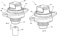
- Figures 1A-1D show an exploded perspective view, a perspective view, a bottom exploded perspective view and a bottom perspective view of a pressure sensor 1 according to an embodiment of the present invention, respectively.
- a pressure sensor 1 comprises in generally a housing 100 and a sensing element 200 (which is not illustrated in Figures 1A-1D , but can refer to Figure 3 ).
- the sensing element 200 is mounted in the housing 100.
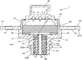
- FIG 3 a cross-sectional view of the pressure sensor 1 according to an embodiment of the present invention.
- a housing cavity 110 is formed at an upper portion of the housing 100.
- the housing cavity 110 is generally cylindrical, but not limited to this.
- the housing cavity can also be rectangular, square, conical and other regular or irregular shape.
- the sensing element 200 is contained in the housing cavity 110. During operation, the sensing element 200 is in contact with the liquid (e.g., aqueous urea solution), so as to sense the pressure of the liquid.
- the liquid e.g., aqueous urea solution
- the sensing element 200 is fixedly disposed in the housing 100, that is, the sensing element 200 is fixed with respect to the housing 100, so as to form a rigid enclosed configuration together with other components.
- the sensing element 200 is rigidly secured in the housing cavity 110.
- the pressure sensor 1 further comprises an electrical connection 400, which is disposed on the sensing element 200 and is electrically connected to the sensing element 200, so as to transmit the pressure signs sensed by the sensing element 200.
- a pressure tube 120 is formed on a lower portion of the housing 100.
- the pressure tube 120 is also generally cylindrical, but not limited to this.
- One skilled in the art may design other shapes of the pressure tube if desired, including, but not limited to rectangular, square, conical or the like.
- the pressure tube 120 has a size less than that of the housing cavity 110, so that a shoulder 130 is formed between the pressure tube 120 and the housing cavity 110.
- the sensing element 200 is positioned adjacent to the shoulder 130.
- an inner seal 201 is provided between the sensing element 200 and the shoulder 130, so as to prevent the liquid (e.g., aqueous urea solution) from leaking to the electrical connection 400 through the sensing element 200 in the housing cavity 110.
- liquid e.g., aqueous urea solution
- a communication passageway 127 is formed by the pressure tube 120, and the sensing element 200 is in fluid communication with an outside through the communication passageway 127.
- the pressure sensor 1 is in contact with the liquid to be measured.
- a portion of the liquid to be measured is passed into the pressure sensor 1 to be in contact with the sensing element 200, so that the sensing element 200 can be used to measure the pressure of the liquid.
- the liquid is passed into the pressure sensor 1 through the communication passageway 127 to be in contact with the sensing element 200, so that during the operation of the pressure sensor 1, there is liquid in the communication passageway 127, and the sensing element 200 is in contact with the liquid to measure the pressure of the liquid.
- the pressure tube 120 itself forms with the communication passageway 127.
- the liquid to be measured is passed into the pressure sensor 1 directly through the pressure tube 120, and is in contact with the sensing element 200.
- other structures can be used to form the communication passageway, which will be described further in detail hereafter.
- the liquid to be measured may be frozen (e.g., icing).
- freezing of the liquid will generally cause a volume expansion for example. It is likely for such volume expansion to damage the components in contact with the liquid, for example the sensing element 200, and thus damage the pressure sensor 1.
- the pressure sensor 1 is further provided with a compensating structure 250, so that when there is occurrence of a volume change of a liquid passed into the pressure sensor 1 through the communication passageway, the compensating structure 250 is used to compensate the volume change.
- the compensating structure 250 of the pressure sensor 1 can compensate such volume expansion, so as to avoid the damage of the components in contact with the liquid.
- the one skilled in the art will appreciate that it is only illustrative that the volume change is caused by low temperature.
- the compensating structure of the pressure sensor according to the present invention can also be used to compensate the liquid volume change caused by other factors.
- the compensating structure 250 can be achieved in many ways, including a first compensating structure 250 configured to change (e.g., increase) the volume of the communication passageway 127.
- a second compensating structure 202 is configured to control the freezing sequence of the liquid passed into the pressure sensor.
- a third compensating structure is configured 215 to maintain the liquid volume within the pressure sensor. The three compensating structures may be used together or separately.
- the first compensating structure 250 can comprise a plug 300.
- An embodiment of the plug 300 as a compensating structure will be described in detail below.
- the plug 300 is removably fitted in the pressure tube 120 of the housing 100.
- the plug 300 has a shape generally mated with the shape of the pressure tube 120 and/or the communication passageway 127, that is in the illustrated embodiment, the plug 300 is also generally cylindrical, but not limited to this.
- the one skilled in the art may design other shapes of the plug if desired, including, but not limited to rectangular, square, conical or the like.
- FIGS 2A-2C show a perspective view, a cross-sectional view and a longitudinal section view of the plug 300 according to an embodiment of the present invention, respectively.
- the plug 300 includes a top or first end 311, a bottom or second end 312 and an outer side wall 301 extended between the first end 311 and the second end 312.
- the first end 311, the second end 312 and outer side wall 301 constitute a generally cylindrical shape.
- the plug 300 is formed with a through-hole 303, which extends in an axial direction of the plug 300.
- the through-hole 303 constitutes at least a portion of the communication passageway 127.
- the liquid to be measured is passed into the pressure sensor 1 through the through-channel 303, and is in contact with the sensing element 200.
- the communication passageway is comprised of the through-hole 303, so that the liquid is passed into the pressure sensor 1 directly through the through-channel 303.
- the through-hole 303 may be used to form the communication passageway together with other structures, which will be described further in detail hereafter.
- the through-hole 303 is formed at the center of the plug 300.
- the through-hole can be positioned at other positions of the plug 300, so as to for example be offset from the longitudinal axis of the plug 300. It is possible to select the position of the through-hole 303 according to requirements.
- the portion of the plug 300 used as a portion of the communication passageway 127 can be deformed elastically, so that when the liquid passed into the pressure sensor 1 through the communication passageway 127 (in particular, through the plug 300) has been changed in volume (e.g., a volume expansion caused by freezing of the liquid in the pressure sensor 1), this portion of the plug 300 is deformed elastically to change the volume of the communication passageway, so as to compensate such volume change of the liquid.
- volume e.g., a volume expansion caused by freezing of the liquid in the pressure sensor 1
- a hole wall 302 forms the through-hole 303, which is located radially inside of the outer side wall 301.
- the hole wall 302 is connected with the outer side wall 301 at the first end 311 and the second end 312, so that one or more hollow enclosed chambers 304 are formed between the hole wall 302 and the outer side wall 301. That is, an enclosed chamber 304 is formed in an interior of the plug 300.
- a function of such chamber(s) 304 in the interior is used to receive the deformation of the communication passageway 127, for example the deformation of the through-hole 303 in this embodiment. As a result, pressure from expanding fluid volume is harmlessly relieved.
- the hole wall 302 when the volume of the liquid is increased due to freezing and thus the liquid in the through-hole 303 has an increased volume, the hole wall 302 can be deformed elastically such as in radial direction of the plug in the orientation of the figure, so as to increase the volume of the through-hole 303, the volume used to contain the liquid, and thus compensate the volume expansion of the liquid.
- the hole wall 302 When the hole wall 302 is deformed, such deformation can be received by the chamber 304, so that the hole wall 302 can be further deformed more easily and quickly.
- the enclosed chamber 304 can be formed within the communication passageway 127, such as around the through-hole 303, so as to receive the deformation of the hole wall 302.
- a plurality of ribs 305 are connected between the hole wall 302 and the outer side wall 301, in the chamber 304.
- the plurality of ribs extend in the axial direction and the radial direction of the plug 300.
- These ribs 305 can be arranged symmetrically around the hole wall 302 to facilitate the molding of the plug 300.
- a chamber cover 307 is provided at an upper end of the chamber 304 adjacent to the sensing element 200, that is between the first end 111 and the ribs 305, wherein the chamber cover 307 is used to prevent the molding materials getting into the chamber 304 during the molding of the plug 300.
- the first end 311 of the plug 300 is positioned adjacent to the sensing element 200, and the second end 312 is positioned away from the sensing element 200.
- the through-hole 303 is positioned perpendicularly with respect to the sensing element 200, and the sensing element 200 is in communication with the outside of the pressure sensor through the through-hole 303.
- a cavity 202 is formed between the sensing element 200 and the pressure tube 120.
- the cavity 202 is formed below the sensing element 200, between the sensing element 200, the housing 100 and the plug 300.
- the cavity 202 is in communication with the through-hole 303.
- the pressure sensor 1 is mounted in a selective catalytic reduction system, the liquid is passed into the cavity 202 through the through-hole 303, and thus into contact with the sensing element 200, so that the pressure of the liquid can be measured by the pressure sensor 1.
- the cavity 202 is not necessary, and the liquid can be in contact with the sensing element 200 directly after passing through the through-hole 303.
- the cavity 202 is another form of compensating structure, which will be described in detail below.
- the hole wall 302 used to form the through-hole 303 can be deformed, so as to change the volume of the through-hole 303.
- the hole wall 302 is made of an elastically deformable material, including but not limited to rubber, plastic or thermoplastic material.
- the liquid to be measured e.g., aqueous urea solution
- the plug 300 is also a rigid structure, the expanded liquid will apply an increased contact force to the sensing element 200, so as to result in the damage of at least the sensing element 200.
- the hole wall 302 is deformable, so that in the case of the volume of the liquid increasing due to being frozen, the hole wall 302 is deformed to increase the volume of the through-hole 303, i.e. increase the amount of the liquid contained in the through-hole 303, so as to compensate the increased volume of the liquid due to being frozen and thus prevent the damage of the components of the pressure sensor 1 caused by the increased contact force.
- the configuration of the plug 300 can compensate the increased volume of the liquid, so as to prevent the damage of the components of the pressure sensor 1.
- the increased volume of the liquid will apply axially a contact force to the sensing element 200.
- the sensing element 200 is rigidly connected and the hole wall 302 is elastically deformable, the liquid having increased volume will press the hole wall 302 firstly and cause the hole wall 302 to be deformed radially.
- the chamber 304 is formed in the plug 300, the hole wall 302 can be deformed radially and outwardly, so that the through-hole 303 has an increased volume to compensate the increased volume of the liquid and thus prevent the damage of the components of the pressure sensor 1, particularly the sensing element 200.
- the contact force applied due to the increased volume of the liquid and for the corresponding deformation of the hole wall that is, it is not necessary to apply an axial force to the sensing element and for the hole wall to be deformed radially.
- the damage of the components of the pressure sensor can be prevented as long as portion of the plug such as the hole wall is deformed to make the through-hole be expanded and thus can compensate the volume expansion.
- the through-hole 303 can be elongated, which facilitates the deformation of the hole wall 302, while reducing the volume of the liquid contained (and in turn can reduce the volume expansion of the liquid when being frozen).
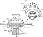
- Figures 4A-4D show a pressure sensor and a plug according to another embodiment of the present invention.
- the structure of this embodiment is generally similar as that shown in Figure 3 , except for the portion of the plug 300 used to constitute the communication passageway 127. Accordingly, the same parts of the embodiment in Figures 4A-4D as those in Figure 3 will be not described in detail here, and only the different portions will be described.
- a through-channel 351 is formed on the perimeter of the plug 300, wherein the through-channel 351 constitutes at least a portion of the communication passageway 127.
- the through-channel 351 is also elongated, which facilitates the deformation of the through-channel 351 while reducing the volume of the liquid contained in the communication passageway 127.
- the top end 311 has a sloped portion 352 and a flat portion 353 adjacent to the sensing element 200.
- the sloped portion 352 also constitutes a portion of the communication passageway 127, wherein the liquid is passed into the pressure sensor 1 through the through-channel 351 and the sloped portion 352, and is in contact with the sensing element 200.
- the sloped portion is not necessary, and only used to facilitate mating with common pressure tube 120. It is also optional to have distinct chambers 304 as shown in Figure 4D . Alternatively, a single large chamber 304, which may or may not be centrally located, can be provided.
- Figures 5A-5B show a pressure sensor 1 and a plug 300 according to another embodiment of the present invention.
- This embodiment shows another form of the compensating structure.
- a groove 125 is formed on an inner wall of the pressure tube 120.
- the plug 300 is not provided with a through-hole or a through-channel. Indeed, in this case, the plug 300 itself cooperates with the groove 125 so as to constitute at least a portion of the communication passageway 127.
- the liquid is passed into the pressure sensor 1 via the groove 125, and is in contact with the sensing element 200.
- the groove 125 can also be preferably elongated, which facilitates the deformation of the portion of the plug 300 cooperated with the groove 125 while reducing the volume of the liquid contained.
- the pressure sensor 1 includes an outer seal ring 122 to facilitate sealing engagement to a desired location.
- This compensating structure is configured to control a freezing sequence of the liquid passed into the pressure sensor, so that the liquid adjacent to the sensing element is frozen prior to the liquid away from the sensing element 200. In this manner, the liquid adjacent to the sensing element will be frozen firstly, and the resulting volume expansion will force a portion of the liquid out of the communication passageway. Therefore, the volume of the liquid within the pressure sensor and the frozen liquid will not be increased, and thus no damage the components of the pressure sensor 1 in contact with the liquid.
- the liquid adjacent to the sensing element 200 will be frozen firstly, and thus the frozen liquid will act to protect the sensing element 200 so that the volume expansion caused by the subsequently frozen liquid has no effect to the sensing element 200, which further prevents the sensing element from being damaged due to the volume expansion.
- This compensating structure comprises the cavity 202 formed between the sensing element 200 and the pressure tube 120.
- the cavity 202 is in fluid communication with the communication passageway 127.
- the cavity 202 has a surface area to volume ratio greater than the surface area to volume ratio of the communication passageway 127. Thus, the liquid in the cavity 202 will freeze first to accomplish the desired benefits.
- control of the freezing sequence of the liquid within the pressure sensor can be considered.
- the effect of the frozen liquid to the components of the sensor can be further reduced, if the liquid in the cavity 202 is frozen first and then the liquid in the through-hole 303 ( Figure 3 ) is frozen.
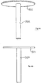
- FIGS 6A and 6B show schematic views of the frozen portion formed by the frozen liquid in the structure of Figure 3 .
- the resulting frozen portion can be divided into two portions, a first frozen portion 501 and a second frozen portion 502.
- the first frozen portion 501 is a frozen liquid portion in the cavity 202
- the second frozen portion 502 is a frozen liquid portion in the through-hole 303.
- the first frozen portion 501 has a shape corresponding to that of the cavity 202
- the second frozen portion 502 has a shape corresponding to that of the through-hole 303.
- Figures 6A and 6B show a shape corresponding to that of the cavity 202 and the through-hole 303.
- the first frozen portion 501 and the second frozen portion 502 are all generally cylindrical. Assuming the first frozen portion 501 has a radius of R and a height of x, the first frozen portion 501 has a surface area of 2 ⁇ ⁇ R 2 + 2 ⁇ R ⁇ x and a volume of ⁇ R 2 ⁇ x, and thus the first frozen portion 501 has a surface area to volume ratio of:
- the second frozen portion 502 has a radius of r and a height of h
- the second frozen portion 502 has a surface area of 2 ⁇ ⁇ r 2 + 2 ⁇ r ⁇ h and a volume of ⁇ r 2 ⁇ h
- the second frozen portion 502 has a surface area to volume ratio of:
- the dashed block in the above two equations can be considered as a constant value due to the size of the sensor.
- R is less than h. Accordingly, through selecting the size of x and r, such as x ⁇ r, it is possible that the surface area to volume ratio of the first frozen portion 501 is greater than the surface area to volume ratio of the second frozen portion 502. If x is much less than r, it is possible that the surface area to volume ratio of the first frozen portion 501 is much greater than the surface area to volume ratio of the second frozen portion 502, that is 2 x + 2 R > > 2 h + 2 r
- the surface area to volume ratio of the cavity 202 is greater than the surface area to volume ratio of the through-hole 303.
- the surface area to volume ratio of the cavity 202 is much greater than the surface area to volume ratio of the through-hole 303.
- R can be about 1mm to 15mm
- x can be about 0.2mm to 5mm
- r can be about 0.25mm to 15mm
- h can be 0.5mm or 20mm.
- a ratio of the surface area to volume ratio of the cavity 202 and the surface area to volume ratio of the through-hole 303 can be preferably in a range from 1.25:1 to 3:1, which can obtain a good control to the freezing sequence of the liquid.
- R can be 4.5mm
- x can be 0.5mm
- r can be 1mm
- h can be 10mm.
- a ratio of the surface area to volume ratio of the cavity 202 and the surface area to volume ratio of the through-hole 303 is on the order of 2:1.
- the surface area to volume ratio can be used as a measurement to show the speed of heat transfer (cooling) of the liquid per unit volume (mass), and the more the value of this ratio is, the quicker the speed of heat transfer will be, and thus the liquid will be frozen quickly (in the case that the thermal conduction factor difference of the contact interface is not taken into consideration). Accordingly, through the above configuration, the liquid in the cavity 202, that is the liquid adjacent to the sensing element 200, can be frozen first, and then the liquid in the through-hole 303 is frozen.
- the volume expansion due to the frozen liquid can be compensated partly, since the liquid in the through-hole 303 has not yet been frozen, so that the volume of the cavity 202 will not be increased. Accordingly, the frozen liquid will not apply an increased contact force to such as the sensing element 200, so as to prevent the damage of the components of the pressure sensor 1.
- the compensating structure is used to control the freezing sequence to compensate the volume expansion due to the frozen liquid, based on the embodiment of Figure 3 .
- the one skilled in the art will appreciate that the compensating structure used to control the freezing sequence can also adapted to other embodiments, such as the embodiments of Figures 4A-4D and 5A-5B , wherein the above technical effect can be achieved through the surface area to volume ratio of the cavity 202 greater than the surface area to volume ratio of the through-channel 351, or greater than the surface area to volume ratio of the groove 125.
- the above technical effect can also be achieved through the surface area to volume ratio of the cavity 202 greater than the surface area to volume ratio of the through-hole 303, the through-channel 351 or the groove 125, as well as the surface area to volume ratio of the communication hole 126.
- the freezing sequence of the liquid contained in the pressure sensor can be controlled through selecting the materials for the component of the pressure sensor.
- the freezing sequence of the liquid can be controlled through the thermal conductivity of the cavity greater than the thermal conductivity of the communication passageway.
- the thermal conductivity of the cavity refers to an average thermal conductivity of the portion of the cavity in contact with the liquid (that is, an average thermal conductivity of the material(s) used to form the cavity)
- the thermal conductivity of the communication passageway refers to an average thermal conductivity of the portion of the communication passageway in contact with the liquid (that is, an average thermal conductivity of the material(s) used to form the communication passageway).
- the average thermal conductivity of the portion(s) adjacent to the cavity 202 is greater than the average thermal conductivity of the portion(s) adjacent to the through-hole 303.
- the thermal conductivity of the portions adjacent to the cavity 202 is high and thus the heat can be transferred quickly, so that the liquid in the cavity 202 is frozen first, and the thermal conductivity of the portions adjacent to the through-hole 303 is low and thus the heat can be transferred slowly, so that the liquid in the through-hole 303 will be frozen subsequently.
- the freezing sequence of the liquid contained in the pressure sensor 1 can be controlled in accordance with the subject technology.
- the average thermal conductivity of the material(s) used to form the sensing element 200 and the housing 100 is greater than the thermal conductivity of the material(s) used to form the plug 300, or otherwise the thermal conductivity of the material(s) used to form the plug 300 is less than the average thermal conductivity of the material(s) used to form the sensing element 200 and the housing 100.
- the sensing element 200 and the housing 100 can be made of metal or plastic having high thermal conductivity, or can be formed by ceramics or semiconductor material, and the plug 300 can be made of rubber or plastic having low thermal conductivity.
- the seal 201 is made of such as rubber.
- the average thermal conductivity of the material(s) used to form the cavity is greater than the average thermal conductivity of the material(s) used to form the communication passageway.
- the materials used to form the portions in contact with the liquid are selected as follows.
- the sensing element 200 is made of ceramics
- the seal 201 is made of rubber
- the pressure tube 102 is made of metal
- the plug 300 is made of rubber, so that a ratio of the average thermal conductivity of the material(s) of the portions used to form the cavity and the average thermal conductivity of the material(s) of the portions used to form the communication passageway is about 35:1, that is, a ratio of the average thermal conductivity of the cavity and the average thermal conductivity of the communication passageway is about 35:1. In this case, it is enough to ensure the liquid adjacent to the sensing element is frozen first. If the ratio of the average thermal conductivity of the cavity and the average thermal conductivity of the communication passageway is greater than 35:1, it is more easily to ensure that the liquid adjacent to the sensing element is frozen first, so as to prevent the damage of the sensing element.
- the cavity 202 is formed between the sensing element 200, the housing 100 and the plug 300, that is a portion of the plug 300 is used to form the cavity 202.
- the surface of the first end 311 of the plug 300 is used to form a portion of the cavity 202.
- a portion of the liquid in the cavity 202 will be in contact with the first end 311 of the plug 300, so that the freezing speed of this portion becomes slower due to the material of the plug 300.
- the following means can be considered.
- the pressure tube 120 of the housing 100 is formed with an inwardly extended flange 121, which is positioned between the sensing element 200 and the communication passageway 127.
- a communication hole 126 is formed in the flange 121, wherein the communication hole 126 constitutes a portion of the communication passageway 127.
- the liquid is passed through the through-hole 303, the through-channel 351 or the groove 125, into the pressure sensor 1, and further through the communication hole 126 in the flange 121, so as to be in contact with the sensing element 200.
- annular boss 306 is formed at the first end 311 of the plug 300 around the through-hole 303, and extends outwardly from the first end 311.
- the flange 121 covers the first end 311 of the plug 300 around the annular boss 306 of the plug 300.
- the annular boss 306 and the flange 121 replace the first end 311 to form a portion of the cavity 202.
- the above annular boss 306 is not necessary.
- the flange 121 can more fully or even fully cover the plug 300, as shown in Figures 4D and 5B .
- the flange 121 can be made of a material having high thermal conductivity, e.g., metal or plastic having high thermal conductivity. Therefore, the thermal conductivity of the portions in contact with the liquid in the cavity 202 can be further increased, so as to further enhance the effect brought by controlling the freezing speed.
- the effect of controlling the freezing speed can be enhanced through not only the above means but also other ways.
- the first end of the plug can be a two parts design, that is, an annular boss is formed at the first end of the plug around the through-hole and extends outwardly from the first end, meanwhile such as a metal cover is provided around the annular boss to cover the first end of the plug and is fixedly connected to the first end.
- the chamber cover 307 is rigid or semi-rigid, e.g., can be made of a rigid or semi-rigid material, including but not limited to rubber, plastic, metal, ceramics and the like.
- the rigid or semi-rigid chamber cover 307 abuts against the outer side wall 301 and applies an outwardly radial force to the outer side wall 301 so as to press the outer side wall 301.
- an interference fit will be formed between the plug 300 and the pressure tube 120, so as to facilitate the plug 300 being closely fitted into the pressure tube 120 of the housing 100, to substantially reduce the risk of the plug 300 being disengaged from the pressure tube.
- no additional mating structure is needed to ensure the close fitting between the plug and the pressure tube.
- the third compensating structure can comprise a mounting member 275, which is used for mounting the pressure sensor 1.
- the mounting member 275 is disposed on an outer side surface of the housing 100 of the pressure sensor 1.
- the mounting member 275 is elastic, so that when a force is applied to the pressure sensor 1 (e.g., the volume expansion caused by the frozen liquid in the pressure sensor 1 will apply a force to the pressure sensor 1), the mounting member 275 can be deformed elastically, so as to maintain the volume of the liquid in the pressure sensor 1.
- the mounting member 275 can be achieved in many ways to be elastically deformable to compensate the volume expansion caused by the frozen liquid.
- the mounting member 275 can be a form of a mounting flange 140.
- the third compensating structure of the present invention now will be described by an example of the mounting flange 140.
- the mounting member 275 is not limited to the mounting flange 140.
- a mounting flange 140 is provided on the outer side surface of the housing 100 as the third compensating structure.
- the mounting flange 140 is provided on the outer side surface of the housing cavity 110 of the housing 100.
- the mounting flange 140 is elastic, and can be made of an elastomer, e.g., can be made of plastic or metal, so that the mounting flange 140 can be deformed elastically when a force is applied to the pressure sensor 1.
- Amounting hole 141 is formed on the mounting flange 140.
- the pressure sensor 1 is mounted onto such as a selective catalytic reduction system, via a fastener (not shown) through the mounting hole 141 on the mounting flange 140.
- a fastener not shown
- the mounting flange 140 is elastically deformable, in the case of the increased contact force, the mounting flange 140 can be deformed elastically, so that the sensor 1 can move in a deformation direction of the mounting flange 140, and thus a portion of the liquid in the sensor 1 will move out of the sensor 1 when the liquid is frozen, so as to maintain the volume of the remained liquid in the sensor 1, compensate partly the volume expansion caused by the frozen liquid, and further reduce or prevent the damage of the components of the pressure sensor 1.
- the flexible mounting member 275 allows the housing 100 to deflect and deform as needed.
- FIGS 7A-7D are schematic views showing the steps of forming the plug according to an embodiment of the present invention.
- a method for manufacturing the plug 300 includes a primary molding step of molding a body 310 using elastomeric material, so that a chamber 304 or plurality of chambers 304 are formed in the interior of the body ( Figure 7A ).
- the method next includes a covering step of placing a chamber cover 307 to enclosed chamber so as to enclose the chamber(s) 304 ( Figures 7A and 7B ).
- Another molding step includes molding a secondary molding material 330 onto the chamber cover 307 ( Figures 7B and 7C ).
- the above method can further comprise a fusing step of fusing the body formed through the primary molding step and the portion (e.g., material 330) formed through the secondary molding step, so as to form a complete plug 300 and a sealed enclosed chamber 304 ( Figure 7D ).
- the molding steps of the plug include a primary molding step of molding a body 310 provided with an inner cavity 313 and a through-hole 303.
- the body 310 includes a hole wall 302 used to form the through-hole 303 and an outer side wall 301.
- the hole wall 302 forms the through-hole 303 radially inward of the outer side wall 301.
- the inner cavity 313 is formed between the hole wall 302 and the outer side wall 301.
- the hole wall 302 is connected with the outer side wall 301 at the lower end 312.
- a plurality of ribs 305 are connected between the hole wall 302 and the outer side wall 301.
- the plurality of ribs 305 extend in the axial direction and the radial direction of the plug 300. These ribs 305 can be arranged symmetrically or asymmetrically around the hole wall 302 to facilitate the molding of the plug 300 as would be appreciated by those of ordinary skill in the molding arts.
- a covering step includes placing a chamber cover 307 onto an upper end of the body 310, so as to cover the inner cavity 313.
- the chamber cover 307 is used to prevent migration of the molding materials into the chamber 304 during the molding of the plug 300.
- the chamber cover 307 is ring-shaped with a central hole 308.
- the chamber cover 307 can be rigid, for example can be made of a rigid material, so as to facilitate the plug 300 to be closely fitted into the pressure tube 120 of the housing 100.
- a secondary molding step includes molding a secondary molding material 330 onto an upper end of the body 310 above the chamber cover 307.
- the secondary molding material 330 has a generally annular shape with a central opening 331.
- the secondary molding material 330 is disposed around the hole wall 302 and the through-hole 303.
- a fusing step includes fusing the body 310 formed through the primary molding step and the secondary molding material 330, so as to form a complete plug 300 and a sealed inner chamber 304, i.e. a hollow structure. After fusing, the plug 300 with the structure of Figures 2A-2C is complete.
- the method is generally similar, except that in the primary molding step, a through-channel 351 is formed on a perimeter of the body 310, rather than a through-hole is formed in the body. Further, in the case that the sloped portion 352 is provided, the sloped portion is formed in the primary molding step, the secondary molding step and/or the fusing step.
- the pressure sensor, a plug used with the pressure sensor and a method for manufacturing the plug according to the present invention have substantial technical advantages.
- the volume expansion due to liquid freezing can be compensated to avoid the damage of the sensing element etc., by means of the deformation of the portion used to constitute the communication passageway to change the volume of the communication passageway, controlling the freezing sequence of the liquid within the cavity, or being provided with an elastic mounting flange, or the like. Even in the case of the most restrict enclosed freezing (a freezing under the liquid fully filling the space of an enclosed sensor), the volume expansion due to liquid freezing can be compensated effectively, so as to prevent damage of the components of the pressure sensor.
- the plug can be suitable for different application requirements (temperature, medium, pressure or the like). From the above, it can be seen that it is possible for the plug to select the material, the thermal conductivity or the like according to different application requirements.
- the rigid cover can provide advantageous fitting, so as to simplify the configuration.
- the flange being made of plastic or metal sheet also can compensate at least partly the volume expansion due to liquid freezing.
- the plug is flexible, and thus can be used in applications with different configuration and size. From the above, it can be seen that the plug is an independent component mounted in the pressure tube, so that a suitable plug can be selected according to the configuration and size of the application, and the same plug can be used in other pressure sensors having the same size, which is universal. The plug does not need to be designed especially since it can be an optional accessory.
Landscapes
- Physics & Mathematics (AREA)
- General Physics & Mathematics (AREA)
- Measuring Fluid Pressure (AREA)
Abstract
Description
- The invention relates to the field of sensors, and in particular, the present invention relates to a pressure sensor, which is primarily used to measure the pressure of a liquid, particularly an aqueous urea solution.
- The present invention further relates to a plug used with the pressure sensor and a method for manufacturing the plug.
- It is well known to measure the pressure of a liquid by using a pressure sensor. During a measuring process, generally the pressure sensor will be in contact with the liquid to be measured. In particular, the liquid passes into the pressure sensor and contacts a sensing element, so that the pressure of the liquid can be measured.
- In some case, the liquid passed into the pressure sensor may be frozen due to such as a low temperature and converted into solid phase, which will cause a volume expansion and thus the damage of the components of the pressure sensor, particularly the components which are in contact with the liquid, for example the sensing element.
- It is well known that a mass of contamination emission may be generated in industrial applications. For example, a mass of exhaust containing nitric oxides (NOx) will be discharged from the vehicle. Many technical solutions have been developed to reduce these emissions. Selective catalytic reduction (SCR) is one solution that is widely used.
- In most selective catalytic reduction system, aqueous urea solution (AUS) is generally used as a working medium, such as 32.5% aqueous urea solution, so as to reduce the content of the nitric oxides. In recent selective catalytic reduction system, a urea pressure sensor (UPS) is generally used to monitor the pressure of the aqueous urea solution, to ensure normal operation of the selective catalytic reduction system. During operation, a portion of the urea pressure sensor (e.g., the sensing element) will be in contact with the aqueous urea solution, so as to measure the pressure of the aqueous urea solution.
- However, with respect to the selective catalytic reduction system, a key technical problem is that the aqueous urea solution will be frozen at a temperature of about -11°C or less. The volume of the aqueous urea solution will be increased after being frozen, so that a contact force between the aqueous urea solution and the sensing element of the urea pressure sensor will be increased, which will result in damage of the components (e.g., sensing element) of the urea pressure sensor in contact with the aqueous urea solution.
- In the case of using a selective catalytic reduction system, such as in a vehicle, it is possible for the system to be subjected to a temperature of about -11 °C or less. In this case, it is a challenge how to address the effect of the frozen aqueous urea solution to the operation of the selective catalytic reduction system.
- An object of the present invention is to provide a pressure sensor, particularly a urea pressure sensor, so as to overcome the above drawbacks in the art.
- An object of the present invention is to provide a pressure sensor, such that when the liquid within the pressure sensor has an increased volume due to being frozen, such increased volume can be compensated, so as to prevent the components of the pressure sensor from being damaged.
- Another object of the present invention is to provide a pressure sensor, which can control the freezing sequence of the liquid within the pressure sensor, so as to prevent the components of the pressure sensor from being damaged.
- Another object of the present invention is to provide a pressure sensor, which utilizes various assistance means to compensate the increased volume of the frozen liquid of the pressure sensor.
- Another object of the present invention is to provide a plug used with the pressure sensor and a method for manufacturing the plug.
- The above and other objects of the present invention are achieved via the following technical solutions.
- An aspect of the invention provides a pressure sensor, comprising:
- a housing defining a communication passageway;
- a sensing element disposed in the housing, the sensing element being in fluid communication with an outside of the housing through the communication passageway; and
- wherein the pressure sensor is further provided with a compensating structure, so that when a contact force is increased due to occurrence of a volume expansion of a liquid passed into the housing through the communication passageway, the compensating structure compensates for the volume expansion. Thus, the compensating structure compensates the volume expansion for protection of the sensory element.
- One embodiment of the present invention is directed to a pressure sensor including a housing and a sensing element disposed in the housing. A communication passageway is formed in the housing, and the sensing element is in communication with an outside of the housing through the communication passageway. The pressure sensor is provided with a compensating structure, so that when a contact force is increased due to a volume expansion of a liquid passed into the housing through the communication passageway, the compensating structure is used to compensate the volume expansion.
- In one embodiment of the pressure sensor, the compensating structure comprises a first compensating structure configured to increase the volume of the communication passageway and/or a second compensating structure configured to control the freezing sequence of the liquid passed into the pressure sensor. The first compensating structure may be a plug, and a pressure tube formed in the housing, wherein the plug is removably fitted in the pressure tube of the housing.
- In another embodiment of the pressure sensor, the plug is formed with a through-hole which constitutes at least a portion of the communication passageway. A through-channel is formed on a perimeter of the plug, wherein the through-channel constitutes at least a portion of the communication passageway. Alternatively, a groove is formed on an inner wall of the pressure tube, wherein the groove cooperates with the plug so as to constitute at least a portion of the communication passageway.
- In still another embodiment of the pressure sensor, the portion of the plug used to constitute the communication passageway can be deformed elastically to change the volume of the communication passageway.
- In one embodiment of the pressure sensor, an enclosed chamber is formed in an interior of the plug. The chamber facilitates forming the plug during molding. Moreover, the chamber facilitates deforming the portion used to form the communication passageway, so as to compensate the volume expansion of the liquid within the pressure sensor. A chamber cover may be disposed at an end of the chamber adjacent to the sensing element. The chamber cover can prevent molding material from entering into the chamber during molding. The chamber cover can also be configured to assist in fitting the plug into the pressure tube of the housing. For example, the chamber cover may be rigid or semi-rigid. Thus, the chamber cover can form an interference fit between the plug and the pressure tube.
- The second compensating structure may be configured to control the freezing sequence of the liquid passed into the pressure sensor, so that the liquid adjacent to the sensing element is frozen prior to the liquid away from the sensing element. For example, the second compensating structure comprises a cavity formed between the sensing element and the pressure tube of the housing, wherein the cavity is in fluid communication with the communication passageway. Preferably, the cavity has a surface area to volume ratio greater than that of the communication passageway. In one embodiment, a ratio of the surface area to volume ratio of the cavity and the surface area to volume ratio of the communication passageway is in a range from 1. 25 :1 to 3: 1. Typically, a ratio of the surface area to volume ratio of the cavity and the surface area to volume ratio of the communication passageway is about 2:1.
- Preferably, the material used to form the cavity has an average thermal conductivity greater than that of the material used to form the communication passageway. A ratio of the average thermal conductivity of the material used to form the cavity and the average thermal conductivity of the material used to form the communication passageway can be about 35:1 or more.
- In one embodiment of the pressure sensor, the pressure tube of the housing is formed with an inwardly extended flange, which is positioned between the sensing element and the communication passageway and formed with a communication hole used to constitute a portion of the communication passageway. Preferably, the communication passageway is elongated, which facilitates the deformation of the communication passageway while reducing the volume of the liquid contained.
- In one embodiment of the pressure sensor, the compensating structure further comprises a third compensating structure which can be elastically deformed so as to maintain the liquid volume within the pressure sensor, wherein the third compensating structure comprises a mounting member, which is disposed on an outer side surface of the housing and is elastic, so that the mounting member can be elastically deformed so as to maintain the liquid volume within the pressure sensor when a force is applied to the pressure sensor due to the liquid volume expansion.
- Another embodiment is directed to plug used with a pressure sensor. This pressure sensor comprises a housing formed with a pressure tube and a sensing element disposed within the housing, wherein a communication passageway is formed in the pressure tube and the sensing element is in fluid communication with an outside through the communication passageway. The plug is removably fitted in the pressure tube of the housing, and when a contact force is increased due to occurrence of a volume expansion of a liquid passed into the housing through the communication passageway, the plug is used to compensate the volume expansion. The plug may be formed with a through-hole which constitutes at least a portion of the communication passageway. A through-channel is formed on a perimeter of the plug, wherein the through-channel constitutes at least a portion of the communication passageway. A portion of the plug used to constitute the communication passageway can be deformed elastically to change the volume of the communication passageway.
- In one embodiment of the plug, an enclosed chamber is formed in an interior of the plug. The chamber facilitates forming the plug during molding. Moreover, the chamber facilitates the portion used to form the communication passageway to be deformed, so as to compensate the volume expansion of the liquid within the pressure sensor. An annular boss can be formed at an end of the plug adjacent to the sensing element, wherein the annular boss is extended outwardly from the plug around the through-hole. The plug can also have a plurality of ribs formed in the chamber, wherein the plurality of ribs are extended in an axial direction and in a radial direction of the plug. A chamber cover may be disposed at an end of the chamber adjacent to the sensing element. The chamber cover facilitates to prevent a molding material from entering into the chamber during the molding.
- In one embodiment of the plug, the chamber cover is configured to assist in fitting the plug into the pressure tube of the housing. For example, the chamber cover is rigid or semi-rigid, and is made of rigid or semi-rigid material, so as to facilitate to form an interference fit between the plug and the pressure tube. In one embodiment of the plug, the through-hole, the through-channel or the groove is elongated, which facilitates the deformation of the communication passageway while reducing the volume of the liquid contained. The material used to form the plug has a thermal conductivity less than the average thermal conductivity of the material used to form the sensing element and the pressure tube.
- The present invention further relates to a method for manufacturing a plug for use with a pressure sensor. The method includes the steps of molding a body using elastomeric material, so that an enclosed chamber is formed in the interior of the body, placing a chamber cover onto the enclosed chamber so as to cover the enclosed chamber, and molding a secondary molding material onto the chamber cover. In one embodiment of the method, the method further comprises the step of fusing the body formed through the primary molding step and the portion formed through the secondary molding step, so as to form a complete housing and a sealed enclosed chamber. In the primary molding step, a plurality of ribs can be formed in the enclosed chamber, wherein the plurality of ribs are extended in an axial direction and in a radial direction of the plug.
- In one embodiment of the method, in the primary molding step, a through-hole is formed in the body, or a through-channel is formed on a perimeter of the body.
- In one embodiment of the method, in the secondary molding step, an annular boss is formed at an upper end of the body, wherein the annular boss is extended outwardly from the body around the through-hole. The secondary molding material may have a generally annular shape and is disposed around the through-hole.
- As can be seen from the subject disclosure, the pressure sensor, a plug used with the pressure sensor and a method for manufacturing the plug according to the present invention have substantial technical advantages. One advantage is that volume expansion due to liquid freezing can be compensated to avoid the damage of the sensing element and other components by means of the deformation of the portion used to constitute the communication passageway to change the volume of the communication passageway, controlling the freezing sequence of the liquid within the cavity, or being provided with an elastic mounting flange, and the like. Even in the case of the most restrict enclosed freezing (e.g., a freezing under the liquid fully filling the space of an enclosed sensor), the volume expansion due to liquid freezing can be compensated effectively, so as to prevent the damage of the components of the pressure sensor.
Another advantage is that the plug can be suitable for different application requirements (e.g., temperature, medium, pressure or the like). From the above, it can be seen that it is possible for the plug material to be selected for the thermal conductivity or the like according to different application requirements. Still another advantage is that the rigid cover can provide advantageous fitting, so as to simplify the configuration. Advantageously, the flange can be made of plastic or metal sheet to also compensate at least partly the volume expansion due to liquid freezing. - Yet another advantage is that the plug is flexible, and thus can be used in applications with different configurations and sizes. From the above, it can be seen that the plug is an independent component mounted in the pressure tube, so that a suitable plug can be selected according to the configuration and size of the application, and the same plug can be used in other pressure sensors having the same size, which is universal. The plug does not need to be designed especially since it can be an optional accessory.
- It should be appreciated that the subject technology can be implemented and utilized in numerous ways, including without limitation as a process, an apparatus, a system, a device, a method for applications now known and later developed. These and other unique features of the system disclosed herein will become more readily apparent from the following description and the accompanying drawings.
- The above and other features of the present invention will be more apparent and better understood from the following description in connection with the accompanying drawings, described below.
-
Figure 1A is an exploded, perspective view of the pressure sensor according to an embodiment of the present invention. -
Figure 1B is a perspective view of the pressure sensor according to an embodiment of the present invention. -
Figure 1C is a bottom exploded, perspective view of the pressure sensor according to an embodiment of the present invention. -
Figure 1D is a bottom perspective view of the pressure sensor according to an embodiment of the present invention. -
Figure 2A is a perspective view of the plug according to an embodiment of the present invention. -
Figure 2B is a cross-sectional view of the plug according to an embodiment of the present invention. -
Figure 2C is a longitudinal section view of the plug according to an embodiment of the present invention. -
Figure 3 is a cross-sectional view of the pressure sensor according to an embodiment of the present invention. -
Figures 4A-4D are schematic views of the pressure sensor and the plug according to another embodiment of the present invention. -
Figures 5A-5B are schematic views of the pressure sensor and the plug according to another embodiment of the present invention. -
Figure 6A is a schematic view showing the general shape of the liquid frozen in the pressure sensor according to an embodiment of the present invention. -
Figure 6B is a schematic view showing the general shape of the liquid frozen in the pressure sensor according to an embodiment of the present invention. -
Figures 7A-7D are schematic views showing the steps of forming the plug according to an embodiment of the present invention. - The advantages, and other features of the technology disclosed herein, will become more readily apparent to those having ordinary skill in the art from the following detailed description of certain preferred embodiments taken in conjunction with the drawings which set forth representative embodiments of the present technology. It is noted that directional terms (e.g., up, down, left, right, horizontal, vertical etc.) are used below with respect to the figures and not meant in a limiting sense. Some embodiments of the present invention will be described now with respect to the accompanying drawings.
- The present invention provides a pressure sensor, which is primarily used to measure the pressure of a liquid, and can prevent the components of the pressure sensor from being damaged when the liquid freezes, particularly under enclosed freezing of the liquid. For example, in a vehicle, in order to reduce the nitric oxides, a selective catalytic reduction system is generally used, wherein an aqueous urea solution is generally used as a working medium in the selective catalytic reduction system. The pressure sensor of the present invention can be applied to such selective catalytic reduction system, as an aqueous urea solution pressure sensor. The pressure sensor may not be damaged even in the case of a serious enclosed freezing. Of course, the pressure sensor of the present invention is not limited to the above application. In fact, one skilled in the art will appreciate that the above aqueous urea solution is only illustrative, and the pressure sensor of the present invention can be used to measure the pressure of a variety of liquids.
-
Figures 1A-1D show an exploded perspective view, a perspective view, a bottom exploded perspective view and a bottom perspective view of apressure sensor 1 according to an embodiment of the present invention, respectively. - As illustrated, a
pressure sensor 1 according to an embodiment of the present invention comprises in generally ahousing 100 and a sensing element 200 (which is not illustrated inFigures 1A-1D , but can refer toFigure 3 ). Thesensing element 200 is mounted in thehousing 100. -
Figure 3 a cross-sectional view of thepressure sensor 1 according to an embodiment of the present invention. Referring toFigure 3 , ahousing cavity 110 is formed at an upper portion of thehousing 100. In the illustrated embodiment, thehousing cavity 110 is generally cylindrical, but not limited to this. One skilled in the art will appreciate that the housing cavity can also be rectangular, square, conical and other regular or irregular shape. Thesensing element 200 is contained in thehousing cavity 110. During operation, thesensing element 200 is in contact with the liquid (e.g., aqueous urea solution), so as to sense the pressure of the liquid. - Typically, the
sensing element 200 is fixedly disposed in thehousing 100, that is, thesensing element 200 is fixed with respect to thehousing 100, so as to form a rigid enclosed configuration together with other components. In the illustrated embodiment, thesensing element 200 is rigidly secured in thehousing cavity 110. - The
pressure sensor 1 further comprises anelectrical connection 400, which is disposed on thesensing element 200 and is electrically connected to thesensing element 200, so as to transmit the pressure signs sensed by thesensing element 200. - A
pressure tube 120 is formed on a lower portion of thehousing 100. In the illustrated embodiment, thepressure tube 120 is also generally cylindrical, but not limited to this. One skilled in the art may design other shapes of the pressure tube if desired, including, but not limited to rectangular, square, conical or the like. Thepressure tube 120 has a size less than that of thehousing cavity 110, so that ashoulder 130 is formed between thepressure tube 120 and thehousing cavity 110. Thesensing element 200 is positioned adjacent to theshoulder 130. - In a preferable embodiment, an
inner seal 201 is provided between thesensing element 200 and theshoulder 130, so as to prevent the liquid (e.g., aqueous urea solution) from leaking to theelectrical connection 400 through thesensing element 200 in thehousing cavity 110. - A
communication passageway 127 is formed by thepressure tube 120, and thesensing element 200 is in fluid communication with an outside through thecommunication passageway 127. During the operation of thepressure sensor 1, thepressure sensor 1 is in contact with the liquid to be measured. A portion of the liquid to be measured is passed into thepressure sensor 1 to be in contact with thesensing element 200, so that thesensing element 200 can be used to measure the pressure of the liquid. In particular, the liquid is passed into thepressure sensor 1 through thecommunication passageway 127 to be in contact with thesensing element 200, so that during the operation of thepressure sensor 1, there is liquid in thecommunication passageway 127, and thesensing element 200 is in contact with the liquid to measure the pressure of the liquid. - In one embodiment, the
pressure tube 120 itself forms with thecommunication passageway 127. The liquid to be measured is passed into thepressure sensor 1 directly through thepressure tube 120, and is in contact with thesensing element 200. In other embodiments, other structures can be used to form the communication passageway, which will be described further in detail hereafter. - When the operation environment of the
pressure sensor 1 is changed, for example when the temperature is decreased, the liquid to be measured may be frozen (e.g., icing). One skilled in the art will appreciate that the freezing of the liquid will generally cause a volume expansion for example. It is likely for such volume expansion to damage the components in contact with the liquid, for example thesensing element 200, and thus damage thepressure sensor 1. - Therefore, according to the present invention, the
pressure sensor 1 is further provided with a compensatingstructure 250, so that when there is occurrence of a volume change of a liquid passed into thepressure sensor 1 through the communication passageway, the compensatingstructure 250 is used to compensate the volume change. For example, as described above, when the liquid to be measured is frozen due to low temperature, the volume of the liquid expands. The compensatingstructure 250 of thepressure sensor 1 can compensate such volume expansion, so as to avoid the damage of the components in contact with the liquid. However, the one skilled in the art will appreciate that it is only illustrative that the volume change is caused by low temperature. The compensating structure of the pressure sensor according to the present invention can also be used to compensate the liquid volume change caused by other factors. - According to a principle of the present invention, the compensating
structure 250 can be achieved in many ways, including a first compensatingstructure 250 configured to change (e.g., increase) the volume of thecommunication passageway 127. A second compensatingstructure 202 is configured to control the freezing sequence of the liquid passed into the pressure sensor. A third compensating structure is configured 215 to maintain the liquid volume within the pressure sensor. The three compensating structures may be used together or separately. - When there is a volume change of the liquid passed into the
pressure sensor 1, these compensating structures are all used to compensate such volume change, although the compensating structures have different structures and principles. These illustrative compensating structures will be described in detail below. One skilled in the art will appreciate that these compensating structures can function independently or combine to obtain a better compensating effect. Meanwhile, one skilled in the art will appreciate that these compensating structures are only illustrative and not limited. Other compensating ways are possible without departing from the spirit and scope of the present invention. - In an embodiment of the present invention, the first compensating
structure 250 can comprise aplug 300. An embodiment of theplug 300 as a compensating structure will be described in detail below. - The
plug 300 is removably fitted in thepressure tube 120 of thehousing 100. Theplug 300 has a shape generally mated with the shape of thepressure tube 120 and/or thecommunication passageway 127, that is in the illustrated embodiment, theplug 300 is also generally cylindrical, but not limited to this. The one skilled in the art may design other shapes of the plug if desired, including, but not limited to rectangular, square, conical or the like. -
Figures 2A-2C show a perspective view, a cross-sectional view and a longitudinal section view of theplug 300 according to an embodiment of the present invention, respectively. Theplug 300 includes a top orfirst end 311, a bottom orsecond end 312 and anouter side wall 301 extended between thefirst end 311 and thesecond end 312. Thefirst end 311, thesecond end 312 andouter side wall 301 constitute a generally cylindrical shape. - The
plug 300 is formed with a through-hole 303, which extends in an axial direction of theplug 300. The through-hole 303 constitutes at least a portion of thecommunication passageway 127. The liquid to be measured is passed into thepressure sensor 1 through the through-channel 303, and is in contact with thesensing element 200. In one embodiment, the communication passageway is comprised of the through-hole 303, so that the liquid is passed into thepressure sensor 1 directly through the through-channel 303. In other embodiments, the through-hole 303 may be used to form the communication passageway together with other structures, which will be described further in detail hereafter. - In the illustrated embodiment, the through-
hole 303 is formed at the center of theplug 300. However, this is only illustrative, and the one skilled in the art will appreciate that the position of the through-hole 303 is not limited to the center of theplug 300. The through-hole can be positioned at other positions of theplug 300, so as to for example be offset from the longitudinal axis of theplug 300. It is possible to select the position of the through-hole 303 according to requirements. - The portion of the
plug 300 used as a portion of thecommunication passageway 127 can be deformed elastically, so that when the liquid passed into thepressure sensor 1 through the communication passageway 127 (in particular, through the plug 300) has been changed in volume (e.g., a volume expansion caused by freezing of the liquid in the pressure sensor 1), this portion of theplug 300 is deformed elastically to change the volume of the communication passageway, so as to compensate such volume change of the liquid. - A
hole wall 302 forms the through-hole 303, which is located radially inside of theouter side wall 301. Thehole wall 302 is connected with theouter side wall 301 at thefirst end 311 and thesecond end 312, so that one or more hollowenclosed chambers 304 are formed between thehole wall 302 and theouter side wall 301. That is, anenclosed chamber 304 is formed in an interior of theplug 300. A function of such chamber(s) 304 in the interior is used to receive the deformation of thecommunication passageway 127, for example the deformation of the through-hole 303 in this embodiment. As a result, pressure from expanding fluid volume is harmlessly relieved. - For example, as for the embodiment of
Figure 3 , when the volume of the liquid is increased due to freezing and thus the liquid in the through-hole 303 has an increased volume, thehole wall 302 can be deformed elastically such as in radial direction of the plug in the orientation of the figure, so as to increase the volume of the through-hole 303, the volume used to contain the liquid, and thus compensate the volume expansion of the liquid. When thehole wall 302 is deformed, such deformation can be received by thechamber 304, so that thehole wall 302 can be further deformed more easily and quickly. - In a preferable embodiment, the
enclosed chamber 304 can be formed within thecommunication passageway 127, such as around the through-hole 303, so as to receive the deformation of thehole wall 302. - During the molding of the
plug 300, in order to facilitate the molding and demolding of theouter side wall 301 and thehole wall 302, a plurality ofribs 305 are connected between thehole wall 302 and theouter side wall 301, in thechamber 304. The plurality of ribs extend in the axial direction and the radial direction of theplug 300. Theseribs 305 can be arranged symmetrically around thehole wall 302 to facilitate the molding of theplug 300. - As shown in
Figure 2C , in thechamber 304, achamber cover 307 is provided at an upper end of thechamber 304 adjacent to thesensing element 200, that is between the first end 111 and theribs 305, wherein thechamber cover 307 is used to prevent the molding materials getting into thechamber 304 during the molding of theplug 300. - Referring to
Figure 3 , when theplug 300 is fitted in thepressure tube 120, thefirst end 311 of theplug 300 is positioned adjacent to thesensing element 200, and thesecond end 312 is positioned away from thesensing element 200. In this case, as shown inFigure 3 , the through-hole 303 is positioned perpendicularly with respect to thesensing element 200, and thesensing element 200 is in communication with the outside of the pressure sensor through the through-hole 303. - A
cavity 202 is formed between thesensing element 200 and thepressure tube 120. As for the embodiment ofFigure 3 , thecavity 202 is formed below thesensing element 200, between thesensing element 200, thehousing 100 and theplug 300. Thecavity 202 is in communication with the through-hole 303. When thepressure sensor 1 is mounted in a selective catalytic reduction system, the liquid is passed into thecavity 202 through the through-hole 303, and thus into contact with thesensing element 200, so that the pressure of the liquid can be measured by thepressure sensor 1. However, one skilled in the art will appreciate, thecavity 202 is not necessary, and the liquid can be in contact with thesensing element 200 directly after passing through the through-hole 303. Thecavity 202 is another form of compensating structure, which will be described in detail below. - According to an embodiment of the present invention, the
hole wall 302 used to form the through-hole 303 can be deformed, so as to change the volume of the through-hole 303. In one embodiment, thehole wall 302 is made of an elastically deformable material, including but not limited to rubber, plastic or thermoplastic material. As such, when the ambient temperature is at -11 °C or less, the liquid to be measured (e.g., aqueous urea solution) will freeze, causing the volume of the liquid within the through-hole 303 and thecavity 202 to be increased. If theplug 300 is also a rigid structure, the expanded liquid will apply an increased contact force to thesensing element 200, so as to result in the damage of at least thesensing element 200. Indeed, it is possible for the components of thepressure sensor 1 in contact with the liquid to be damaged due to the increased contact force. In an embodiment of the present invention, thehole wall 302 is deformable, so that in the case of the volume of the liquid increasing due to being frozen, thehole wall 302 is deformed to increase the volume of the through-hole 303, i.e. increase the amount of the liquid contained in the through-hole 303, so as to compensate the increased volume of the liquid due to being frozen and thus prevent the damage of the components of thepressure sensor 1 caused by the increased contact force. - It can be seen from the above that even in the case of the above rigid enclosed configuration (which may cause an enclosed freezing), the configuration of the
plug 300 can compensate the increased volume of the liquid, so as to prevent the damage of the components of thepressure sensor 1. - As for a particular embodiment, referring to
Figure 3 , when the liquid is frozen, the increased volume of the liquid will apply axially a contact force to thesensing element 200. However, since thesensing element 200 is rigidly connected and thehole wall 302 is elastically deformable, the liquid having increased volume will press thehole wall 302 firstly and cause thehole wall 302 to be deformed radially. At this time, since thechamber 304 is formed in theplug 300, thehole wall 302 can be deformed radially and outwardly, so that the through-hole 303 has an increased volume to compensate the increased volume of the liquid and thus prevent the damage of the components of thepressure sensor 1, particularly thesensing element 200. - Of course, it is not limited to the above configuration for the contact force applied due to the increased volume of the liquid and for the corresponding deformation of the hole wall, that is, it is not necessary to apply an axial force to the sensing element and for the hole wall to be deformed radially. Indeed, according to the present invention, when the volume of the liquid is increased, the damage of the components of the pressure sensor can be prevented as long as portion of the plug such as the hole wall is deformed to make the through-hole be expanded and thus can compensate the volume expansion. Moreover, the through-
hole 303 can be elongated, which facilitates the deformation of thehole wall 302, while reducing the volume of the liquid contained (and in turn can reduce the volume expansion of the liquid when being frozen). -
Figures 4A-4D show a pressure sensor and a plug according to another embodiment of the present invention. The structure of this embodiment is generally similar as that shown inFigure 3 , except for the portion of theplug 300 used to constitute thecommunication passageway 127. Accordingly, the same parts of the embodiment inFigures 4A-4D as those inFigure 3 will be not described in detail here, and only the different portions will be described. - In the embodiment of
Figures 4A-4D , a through-channel 351 is formed on the perimeter of theplug 300, wherein the through-channel 351 constitutes at least a portion of thecommunication passageway 127. The through-channel 351 is also elongated, which facilitates the deformation of the through-channel 351 while reducing the volume of the liquid contained in thecommunication passageway 127. - In a further embodiment, the
top end 311 has a slopedportion 352 and aflat portion 353 adjacent to thesensing element 200. It can be seen in connection withFigure 4D that the slopedportion 352 also constitutes a portion of thecommunication passageway 127, wherein the liquid is passed into thepressure sensor 1 through the through-channel 351 and the slopedportion 352, and is in contact with thesensing element 200. However, the one skilled in the art will appreciate that the sloped portion is not necessary, and only used to facilitate mating withcommon pressure tube 120. It is also optional to havedistinct chambers 304 as shown inFigure 4D . Alternatively, a singlelarge chamber 304, which may or may not be centrally located, can be provided. -
Figures 5A-5B show apressure sensor 1 and aplug 300 according to another embodiment of the present invention. This embodiment shows another form of the compensating structure. Agroove 125 is formed on an inner wall of thepressure tube 120. Thus, theplug 300 is not provided with a through-hole or a through-channel. Indeed, in this case, theplug 300 itself cooperates with thegroove 125 so as to constitute at least a portion of thecommunication passageway 127. As shown inFigure 5B , the liquid is passed into thepressure sensor 1 via thegroove 125, and is in contact with thesensing element 200. Thegroove 125 can also be preferably elongated, which facilitates the deformation of the portion of theplug 300 cooperated with thegroove 125 while reducing the volume of the liquid contained. Thepressure sensor 1 includes anouter seal ring 122 to facilitate sealing engagement to a desired location. - Another compensating structure according to the present invention, i.e. controlling the freezing sequence, will be described now. This compensating structure is configured to control a freezing sequence of the liquid passed into the pressure sensor, so that the liquid adjacent to the sensing element is frozen prior to the liquid away from the
sensing element 200. In this manner, the liquid adjacent to the sensing element will be frozen firstly, and the resulting volume expansion will force a portion of the liquid out of the communication passageway. Therefore, the volume of the liquid within the pressure sensor and the frozen liquid will not be increased, and thus no damage the components of thepressure sensor 1 in contact with the liquid. Further, the liquid adjacent to thesensing element 200 will be frozen firstly, and thus the frozen liquid will act to protect thesensing element 200 so that the volume expansion caused by the subsequently frozen liquid has no effect to thesensing element 200, which further prevents the sensing element from being damaged due to the volume expansion. - This compensating structure comprises the
cavity 202 formed between thesensing element 200 and thepressure tube 120. Thecavity 202 is in fluid communication with thecommunication passageway 127. Thecavity 202 has a surface area to volume ratio greater than the surface area to volume ratio of thecommunication passageway 127. Thus, the liquid in thecavity 202 will freeze first to accomplish the desired benefits. - In order to further prevent the damage to the components of the
pressure sensor 1 caused by the volume expansion due to the frozen liquid, control of the freezing sequence of the liquid within the pressure sensor can be considered. For example, the effect of the frozen liquid to the components of the sensor can be further reduced, if the liquid in thecavity 202 is frozen first and then the liquid in the through-hole 303 (Figure 3 ) is frozen. - In particular, referring to
Figures 6A and 6B , these figures show schematic views of the frozen portion formed by the frozen liquid in the structure ofFigure 3 . When the liquid is frozen in the structure ofFigure 3 , the resulting frozen portion can be divided into two portions, a firstfrozen portion 501 and a secondfrozen portion 502. The firstfrozen portion 501 is a frozen liquid portion in thecavity 202, and the secondfrozen portion 502 is a frozen liquid portion in the through-hole 303. Accordingly, the firstfrozen portion 501 has a shape corresponding to that of thecavity 202, and the secondfrozen portion 502 has a shape corresponding to that of the through-hole 303. In this case,Figures 6A and 6B show a shape corresponding to that of thecavity 202 and the through-hole 303. - For a simplified illustration, now it will be described how to control the freezing sequence based on the configuration of the
cavity 202 and the through-hole 303 shown inFigure 3 . - The first
frozen portion 501 and the secondfrozen portion 502 are all generally cylindrical. Assuming the firstfrozen portion 501 has a radius of R and a height of x, the firstfrozen portion 501 has a surface area of 2 · πR2 + 2πR · x and a volume of πR2 · x, and thus the firstfrozen portion 501 has a surface area to volume ratio of:
- Likewise, assuming the second
frozen portion 502 has a radius of r and a height of h, the secondfrozen portion 502 has a surface area of 2 · πr2 + 2 πr · h and a volume of πr2 · h, and thus the secondfrozen portion 502 has a surface area to volume ratio of:
- In most sensor applications, the dashed block in the above two equations can be considered as a constant value due to the size of the sensor. In general, R is less than h. Accordingly, through selecting the size of x and r, such as x<r, it is possible that the surface area to volume ratio of the first
frozen portion 501 is greater than the surface area to volume ratio of the secondfrozen portion 502. If x is much less than r, it is possible that the surface area to volume ratio of the firstfrozen portion 501 is much greater than the surface area to volume ratio of the secondfrozen portion 502, that is
- Correspondingly, the surface area to volume ratio of the
cavity 202 is greater than the surface area to volume ratio of the through-hole 303. Alternatively, the surface area to volume ratio of thecavity 202 is much greater than the surface area to volume ratio of the through-hole 303. - As for a common pressure sensor, R can be about 1mm to 15mm, x can be about 0.2mm to 5mm, r can be about 0.25mm to 15mm, h can be 0.5mm or 20mm. In such sensor, a ratio of the surface area to volume ratio of the
cavity 202 and the surface area to volume ratio of the through-hole 303 can be preferably in a range from 1.25:1 to 3:1, which can obtain a good control to the freezing sequence of the liquid. - In a particular embodiment, R can be 4.5mm, x can be 0.5mm, r can be 1mm, and h can be 10mm. As such, a ratio of the surface area to volume ratio of the
cavity 202 and the surface area to volume ratio of the through-hole 303 is on the order of 2:1. - The surface area to volume ratio can be used as a measurement to show the speed of heat transfer (cooling) of the liquid per unit volume (mass), and the more the value of this ratio is, the quicker the speed of heat transfer will be, and thus the liquid will be frozen quickly (in the case that the thermal conduction factor difference of the contact interface is not taken into consideration). Accordingly, through the above configuration, the liquid in the
cavity 202, that is the liquid adjacent to thesensing element 200, can be frozen first, and then the liquid in the through-hole 303 is frozen. - In the case that the liquid in the
cavity 202 is frozen first, the volume expansion due to the frozen liquid can be compensated partly, since the liquid in the through-hole 303 has not yet been frozen, so that the volume of thecavity 202 will not be increased. Accordingly, the frozen liquid will not apply an increased contact force to such as thesensing element 200, so as to prevent the damage of the components of thepressure sensor 1. - The above describes that the compensating structure is used to control the freezing sequence to compensate the volume expansion due to the frozen liquid, based on the embodiment of
Figure 3 . The one skilled in the art will appreciate that the compensating structure used to control the freezing sequence can also adapted to other embodiments, such as the embodiments ofFigures 4A-4D and5A-5B , wherein the above technical effect can be achieved through the surface area to volume ratio of thecavity 202 greater than the surface area to volume ratio of the through-channel 351, or greater than the surface area to volume ratio of thegroove 125. In the case that thepressure tube 120 is provided with aflange 121 which is provided with acommunication hole 126, the above technical effect can also be achieved through the surface area to volume ratio of thecavity 202 greater than the surface area to volume ratio of the through-hole 303, the through-channel 351 or thegroove 125, as well as the surface area to volume ratio of thecommunication hole 126. - In addition to or as an alternative to provide the surface area to volume ratio of the cavity greater than the surface area to volume ratio of the communication passageway to control the freezing sequence, in a preferable embodiment, the freezing sequence of the liquid contained in the pressure sensor can be controlled through selecting the materials for the component of the pressure sensor. In particular, the freezing sequence of the liquid can be controlled through the thermal conductivity of the cavity greater than the thermal conductivity of the communication passageway.
- Herein, the thermal conductivity of the cavity refers to an average thermal conductivity of the portion of the cavity in contact with the liquid (that is, an average thermal conductivity of the material(s) used to form the cavity), and the thermal conductivity of the communication passageway refers to an average thermal conductivity of the portion of the communication passageway in contact with the liquid (that is, an average thermal conductivity of the material(s) used to form the communication passageway).
- For example, through the selection of the materials, the average thermal conductivity of the portion(s) adjacent to the
cavity 202 is greater than the average thermal conductivity of the portion(s) adjacent to the through-hole 303. As such, the thermal conductivity of the portions adjacent to thecavity 202 is high and thus the heat can be transferred quickly, so that the liquid in thecavity 202 is frozen first, and the thermal conductivity of the portions adjacent to the through-hole 303 is low and thus the heat can be transferred slowly, so that the liquid in the through-hole 303 will be frozen subsequently. As a result, the freezing sequence of the liquid contained in thepressure sensor 1 can be controlled in accordance with the subject technology. - In particular, as for an embodiment of the present invention, such as the embodiment shown in
Figure 3 , the average thermal conductivity of the material(s) used to form thesensing element 200 and thehousing 100 is greater than the thermal conductivity of the material(s) used to form theplug 300, or otherwise the thermal conductivity of the material(s) used to form theplug 300 is less than the average thermal conductivity of the material(s) used to form thesensing element 200 and thehousing 100. For example, thesensing element 200 and thehousing 100 can be made of metal or plastic having high thermal conductivity, or can be formed by ceramics or semiconductor material, and theplug 300 can be made of rubber or plastic having low thermal conductivity. In the case of theseal 201, theseal 201 is made of such as rubber. As such, the average thermal conductivity of the material(s) used to form the cavity is greater than the average thermal conductivity of the material(s) used to form the communication passageway. - In a particular embodiment, the materials used to form the portions in contact with the liquid are selected as follows. The
sensing element 200 is made of ceramics, theseal 201 is made of rubber, the pressure tube 102 is made of metal, and theplug 300 is made of rubber, so that a ratio of the average thermal conductivity of the material(s) of the portions used to form the cavity and the average thermal conductivity of the material(s) of the portions used to form the communication passageway is about 35:1, that is, a ratio of the average thermal conductivity of the cavity and the average thermal conductivity of the communication passageway is about 35:1. In this case, it is enough to ensure the liquid adjacent to the sensing element is frozen first. If the ratio of the average thermal conductivity of the cavity and the average thermal conductivity of the communication passageway is greater than 35:1, it is more easily to ensure that the liquid adjacent to the sensing element is frozen first, so as to prevent the damage of the sensing element. - It can be seen from the above that the
cavity 202 is formed between thesensing element 200, thehousing 100 and theplug 300, that is a portion of theplug 300 is used to form thecavity 202. In the embodiment ofFigure 3 , the surface of thefirst end 311 of theplug 300 is used to form a portion of thecavity 202. In this case, a portion of the liquid in thecavity 202 will be in contact with thefirst end 311 of theplug 300, so that the freezing speed of this portion becomes slower due to the material of theplug 300. In order to further enhance the effect brought by controlling the freezing speed, the following means can be considered. - The
pressure tube 120 of thehousing 100 is formed with an inwardlyextended flange 121, which is positioned between thesensing element 200 and thecommunication passageway 127. Acommunication hole 126 is formed in theflange 121, wherein thecommunication hole 126 constitutes a portion of thecommunication passageway 127. For example, in the case of the above embodiment, the liquid is passed through the through-hole 303, the through-channel 351 or thegroove 125, into thepressure sensor 1, and further through thecommunication hole 126 in theflange 121, so as to be in contact with thesensing element 200. - In the case that the
plug 300 is formed with the through-hole 303, anannular boss 306 is formed at thefirst end 311 of theplug 300 around the through-hole 303, and extends outwardly from thefirst end 311. Theflange 121 covers thefirst end 311 of theplug 300 around theannular boss 306 of theplug 300. As such, theannular boss 306 and theflange 121 replace thefirst end 311 to form a portion of thecavity 202. As such, during the operation, the amount of the liquid in thecavity 202 in contact with theplug 300 is reduced substantially. However, the aboveannular boss 306 is not necessary. If there is no theannular boss 306, theflange 121 can more fully or even fully cover theplug 300, as shown inFigures 4D and5B . Theflange 121 can be made of a material having high thermal conductivity, e.g., metal or plastic having high thermal conductivity. Therefore, the thermal conductivity of the portions in contact with the liquid in thecavity 202 can be further increased, so as to further enhance the effect brought by controlling the freezing speed. - Of course, the effect of controlling the freezing speed can be enhanced through not only the above means but also other ways. For example, in order to reduce the portions of the plug in contact with the liquid in the cavity, the first end of the plug can be a two parts design, that is, an annular boss is formed at the first end of the plug around the through-hole and extends outwardly from the first end, meanwhile such as a metal cover is provided around the annular boss to cover the first end of the plug and is fixedly connected to the first end.
- In the case that the plug is made of such as rubber, since the rubber is elastic, it is possible for the plug to be disengaged from the pressure tube when the plug is fitted into the pressure tube of the housing. To this end, the
chamber cover 307 is rigid or semi-rigid, e.g., can be made of a rigid or semi-rigid material, including but not limited to rubber, plastic, metal, ceramics and the like. The rigid orsemi-rigid chamber cover 307 abuts against theouter side wall 301 and applies an outwardly radial force to theouter side wall 301 so as to press theouter side wall 301. As such, in the case that theplug 300 is removably fitted into thepressure tube 120, an interference fit will be formed between theplug 300 and thepressure tube 120, so as to facilitate theplug 300 being closely fitted into thepressure tube 120 of thehousing 100, to substantially reduce the risk of theplug 300 being disengaged from the pressure tube. In this case, no additional mating structure is needed to ensure the close fitting between the plug and the pressure tube. - In addition to the above first and second compensating structure, other compensating structure can be provided according to the embodiment of the present invention, such as a third compensating structure. Referring to
Figure 3 , the third compensating structure can comprise a mountingmember 275, which is used for mounting thepressure sensor 1. The mountingmember 275 is disposed on an outer side surface of thehousing 100 of thepressure sensor 1. The mountingmember 275 is elastic, so that when a force is applied to the pressure sensor 1 (e.g., the volume expansion caused by the frozen liquid in thepressure sensor 1 will apply a force to the pressure sensor 1), the mountingmember 275 can be deformed elastically, so as to maintain the volume of the liquid in thepressure sensor 1. - The mounting
member 275 can be achieved in many ways to be elastically deformable to compensate the volume expansion caused by the frozen liquid. For example, the mountingmember 275 can be a form of a mountingflange 140. The third compensating structure of the present invention now will be described by an example of the mountingflange 140. However, the one skilled in the art will appreciate that the mountingmember 275 is not limited to the mountingflange 140. - As illustrated, in a preferred embodiment of
Figure 3 , a mountingflange 140 is provided on the outer side surface of thehousing 100 as the third compensating structure. For example, the mountingflange 140 is provided on the outer side surface of thehousing cavity 110 of thehousing 100. The mountingflange 140 is elastic, and can be made of an elastomer, e.g., can be made of plastic or metal, so that the mountingflange 140 can be deformed elastically when a force is applied to thepressure sensor 1. - Amounting
hole 141 is formed on the mountingflange 140. Thepressure sensor 1 is mounted onto such as a selective catalytic reduction system, via a fastener (not shown) through the mountinghole 141 on the mountingflange 140. When the liquid in thesensor 1 is frozen, an increased contact force is generated due to the volume expansion of the liquid in thesensor 1. Since the mountingflange 140 is elastically deformable, in the case of the increased contact force, the mountingflange 140 can be deformed elastically, so that thesensor 1 can move in a deformation direction of the mountingflange 140, and thus a portion of the liquid in thesensor 1 will move out of thesensor 1 when the liquid is frozen, so as to maintain the volume of the remained liquid in thesensor 1, compensate partly the volume expansion caused by the frozen liquid, and further reduce or prevent the damage of the components of thepressure sensor 1. In one embodiment, the flexible mountingmember 275 allows thehousing 100 to deflect and deform as needed. - Referring to
Figures 7A-7D below, a method for manufacturing theplug 300 according to the present invention is described.Figures 7A-7D are schematic views showing the steps of forming the plug according to an embodiment of the present invention. According to the present invention, a method for manufacturing theplug 300 is provided. The method includes a primary molding step of molding abody 310 using elastomeric material, so that achamber 304 or plurality ofchambers 304 are formed in the interior of the body (Figure 7A ). The method next includes a covering step of placing achamber cover 307 to enclosed chamber so as to enclose the chamber(s) 304 (Figures 7A and 7B ). Another molding step includes molding asecondary molding material 330 onto the chamber cover 307 (Figures 7B and 7C ). According to a preferable solution, the above method can further comprise a fusing step of fusing the body formed through the primary molding step and the portion (e.g., material 330) formed through the secondary molding step, so as to form acomplete plug 300 and a sealed enclosed chamber 304 (Figure 7D ). - Still referring to
Figures 7A-D , the steps of the method will be described in detail now, with respect to the particular embodiment ofFigure 3 for example. In the case of theplug 300 ofFigure 3 , the molding steps of the plug include a primary molding step of molding abody 310 provided with aninner cavity 313 and a through-hole 303. Thebody 310 includes ahole wall 302 used to form the through-hole 303 and anouter side wall 301. Thehole wall 302 forms the through-hole 303 radially inward of theouter side wall 301. Theinner cavity 313 is formed between thehole wall 302 and theouter side wall 301. Thehole wall 302 is connected with theouter side wall 301 at thelower end 312. A plurality ofribs 305 are connected between thehole wall 302 and theouter side wall 301. The plurality ofribs 305 extend in the axial direction and the radial direction of theplug 300. Theseribs 305 can be arranged symmetrically or asymmetrically around thehole wall 302 to facilitate the molding of theplug 300 as would be appreciated by those of ordinary skill in the molding arts. - A covering step includes placing a
chamber cover 307 onto an upper end of thebody 310, so as to cover theinner cavity 313. Thechamber cover 307 is used to prevent migration of the molding materials into thechamber 304 during the molding of theplug 300. Thechamber cover 307 is ring-shaped with acentral hole 308. Thechamber cover 307 can be rigid, for example can be made of a rigid material, so as to facilitate theplug 300 to be closely fitted into thepressure tube 120 of thehousing 100. - A secondary molding step includes molding a
secondary molding material 330 onto an upper end of thebody 310 above thechamber cover 307. Thesecondary molding material 330 has a generally annular shape with acentral opening 331. Thesecondary molding material 330 is disposed around thehole wall 302 and the through-hole 303. - A fusing step includes fusing the
body 310 formed through the primary molding step and thesecondary molding material 330, so as to form acomplete plug 300 and a sealedinner chamber 304, i.e. a hollow structure. After fusing, theplug 300 with the structure ofFigures 2A-2C is complete. - With respect to the embodiment such as in
Figures 4A-4D , the method is generally similar, except that in the primary molding step, a through-channel 351 is formed on a perimeter of thebody 310, rather than a through-hole is formed in the body. Further, in the case that the slopedportion 352 is provided, the sloped portion is formed in the primary molding step, the secondary molding step and/or the fusing step. - The pressure sensor, a plug used with the pressure sensor and a method for manufacturing the plug according to the present invention have substantial technical advantages.
- The volume expansion due to liquid freezing can be compensated to avoid the damage of the sensing element etc., by means of the deformation of the portion used to constitute the communication passageway to change the volume of the communication passageway, controlling the freezing sequence of the liquid within the cavity, or being provided with an elastic mounting flange, or the like. Even in the case of the most restrict enclosed freezing (a freezing under the liquid fully filling the space of an enclosed sensor), the volume expansion due to liquid freezing can be compensated effectively, so as to prevent damage of the components of the pressure sensor.
- The plug can be suitable for different application requirements (temperature, medium, pressure or the like). From the above, it can be seen that it is possible for the plug to select the material, the thermal conductivity or the like according to different application requirements. The rigid cover can provide advantageous fitting, so as to simplify the configuration. The flange being made of plastic or metal sheet also can compensate at least partly the volume expansion due to liquid freezing. The plug is flexible, and thus can be used in applications with different configuration and size. From the above, it can be seen that the plug is an independent component mounted in the pressure tube, so that a suitable plug can be selected according to the configuration and size of the application, and the same plug can be used in other pressure sensors having the same size, which is universal. The plug does not need to be designed especially since it can be an optional accessory.
- The one skilled in the art will appreciate that while several embodiments have been described, these embodiments are in the scope of the present invention. In the case of no substantial conflict, one or more technical features in one embodiment can be advantageously incorporated into other embodiments, without departing from the scope of the invention. The technical features in all embodiments can be deleted and combined to create new embodiment(s), which may also fall into the scope of the invention. It will be appreciated by those of ordinary skill in the pertinent art that the functions of several elements may, in alternative embodiments, be carried out by fewer elements, or a single element. Similarly, in some embodiments, any functional element may perform fewer, or different, operations than those described with respect to the illustrated embodiment. Also, functional elements shown as distinct for purposes of illustration may be incorporated within other functional elements in a particular implementation.
- Further aspects and preferred features of the invention are set out in the following numbered clauses:
- 1. A pressure sensor, comprising:
- a housing; and
- a sensing element disposed in the housing;
- wherein a communication passageway is formed in the housing, and the sensing element is in fluid communication with an outside of the housing through the communication passageway, and
- wherein the pressure sensor is further provided with a compensating structure, so that when a contact force is increased due to occurrence of a volume expansion of a liquid passed into the housing through the communication passageway, the compensating structure is used to compensate the volume expansion.
- 2. The pressure sensor according to
clause 1, characterized in that, the compensating structure comprises a first compensating structure configured to increase the volume of the communication passageway and/or a second compensating structure configured to control the freezing sequence of the liquid passed into the pressure sensor. - 3. The pressure sensor according to clause 2, characterized in that, the first compensating structure comprises a plug, and a pressure tube is formed in the housing, wherein the plug is removably fitted in the pressure tube of the housing.
- 4. The pressure sensor according to clause 3, characterized in that, the plug is formed with a through-hole which constitutes at least a portion of the communication passageway; a through-channel is formed on a perimeter of the plug, wherein the through-channel constitutes at least a portion of the communication passageway; or a groove is formed on an inner wall of the pressure tube, wherein the groove cooperates with the plug so as to constitute at least a portion of the communication passageway.
- 5. The pressure sensor according to clause 4, characterized in that, the portion of the plug used to constitute the communication passageway can be deformed elastically to change the volume of the communication passageway.
- 6. The pressure sensor according to any one of clauses 3 to 5, characterized in that, the interior of the plug is formed with an enclosed chamber.
- 7. The pressure sensor according to clause 6, characterized in that, a chamber cover is disposed at an end of the chamber adjacent to the sensing element.
- 8. The pressure sensor according to clause 7, characterized in that, the chamber cover is configured to assist in fitting the plug into the pressure tube of the housing.
- 9. The pressure sensor according to any one of clauses 2 to 8, characterized in that, the second compensating structure is configured to control the freezing sequence of the liquid passed into the pressure sensor, so that the liquid adjacent to the sensing element is frozen prior to the liquid away from the sensing element.
- 10. The pressure sensor according to any one of clauses 2 to 9, characterized in that, the second compensating structure comprises a cavity formed between the sensing element and the pressure tube of the housing, wherein the cavity is in fluid communication with the communication passageway.
- 11. The pressure sensor according to clause 10, characterized in that, the cavity has a surface area to volume ratio greater than that of the communication passageway.
- 12. The pressure sensor according to clause 11, characterized in that, a ratio of the surface area to volume ratio of the cavity and the surface area to volume ratio of the communication passageway is in a range from 1. 25:1 to 3:1.
- 13. The pressure sensor according to clause 11, characterized in that, the ratio of the surface area to volume ratio of the cavity and the surface area to volume ratio of the communication passageway is about 2:1.
- 14. The pressure sensor according to any one of clauses 10 to 13, characterized in that, the material used to form the cavity has an average thermal conductivity greater than that of the material used to form the communication passageway.
- 15. The pressure sensor according to clause 14, characterized in that, a ratio of the average thermal conductivity of the material used to form the cavity and the average thermal conductivity of the material used to form the communication passageway is about 35:1 or more.
- 16. The pressure sensor according to any of clauses 3 to clause 15, characterized in that, the pressure tube of the housing is formed with an inwardly extended flange, which is positioned between the sensing element and the communication passageway and formed with a communication hole used to constitute a portion of the communication passageway.
- 17. The pressure sensor according to any one of previous clauses, characterized in that, the communication passageway is elongated.
- 18. The pressure sensor according to any one of clauses 2 to 17, characterized in that, the compensating structure further comprises a third compensating structure which can be elastically deformed so as to maintain the liquid volume within the pressure sensor, wherein the third compensating structure comprises a mounting member, which is disposed on an outer side surface of the housing and is elastic, so that the mounting member can be elastically deformed so as to maintain the liquid volume within the pressure sensor when a force is applied to the pressure sensor due to the liquid volume expansion.
- 19. A plug used with a pressure sensor, the pressure sensor comprising a housing formed with a pressure tube and a sensing element disposed within the housing, wherein a communication passageway is formed in the pressure tube and the sensing element is in fluid communication with an outside through the communication passageway; characterized in that, the plug is removably fitted in the pressure tube of the housing, and when a contact force is increased due to occurrence of a volume expansion of a liquid passed into the housing through the communication passageway, the plug is used to compensate the volume expansion.
- 20. The plug according to clause 19, characterized in that, the plug is formed with a through-hole which constitutes at least a portion of the communication passageway; or the perimeter of the plug is formed with a through-channel which constitutes at least a portion of the communication passageway.
- 21. The plug according to clause 20, characterized in that, the portion of the plug used to constitute the communication passageway can be deformed elastically to change the volume of the communication passageway.
- 22. The plug according to clause 20 or 21, characterized in that, the interior of the plug is formed with an enclosed chamber.
- 23. The plug according to any of clause 22, characterized in that, an annular boss is formed at an end of the plug adjacent to the sensing element, wherein the annular boss is extended outwardly from the plug around the through-hole.
- 24. The plug according to clause 22 or 23, characterized in that, a plurality of ribs are formed in the chamber, wherein the plurality of ribs are extended in an axial direction and in a radial direction of the plug.
- 25. The plug according to any of clauses 22 to 24, characterized in that, a chamber cover is disposed at an end of the chamber adjacent to the sensing element.
- 26. The plug according to clause 25, characterized in that, the chamber cover is configured to assist in fitting the plug into the pressure tube of the housing.
- 27. The plug according to any of clauses 20 to 26, characterized in that, the through-hole, the through-channel or a groove is elongated.
- 28. The plug according to any one of clauses 19 to 27, characterized in that, the material used to form the plug has a thermal conductivity less than the average thermal conductivity of the material used to form the sensing element and the pressure tube.
- 29. A method for manufacturing the plug according to any one of clauses 19 to 27, the method comprising:
- A. a primary moulding step of moulding a body using elastomeric material, so that an enclosed chamber is formed in the interior of the body;
- B. a covering step of placing a chamber cover onto the enclosed chamber so as to cover the enclosed chamber;
- C. a secondary moulding step of moulding a secondary moulding material onto the chamber cover.
- 30. The method according to clause 29, wherein the method further comprises a fusing step of fusing the body formed through the primary moulding step and the portion formed through the secondary moulding step, so as to form a complete housing and a sealed enclosed chamber.
- 31. The method according to clause 29 or 30, wherein in the primary moulding step, a plurality of ribs are formed in the enclosed chamber, wherein the plurality of ribs are extended in an axial direction and in a radial direction of the plug.
- 32. The method according to any one of clauses 29 to 31, wherein in the primary moulding step, a through-hole is formed in the body, or a through-channel is formed on a perimeter of the body.
- 33. The method according to any one of clauses 32, wherein in the secondary moulding step, an annular boss is formed at an upper end of the body, wherein the annular boss is extended outwardly from the body around the through-hole.
- 34. The method according to clause 32 or clause 33, wherein the secondary moulding material has a generally annular shape and is disposed around the through-hole.
- 35. A pressure sensor comprising:
- a housing; and
- a sensing element disposed in the housing;
- wherein a communication passageway is formed in the housing, and sensing element is in fluid communication with an outside of the housing the communication passageway;
- wherein the pressure sensor is further provided with a compensating structure, so that when a liquid passed into the housing through the communication passageway expands in volume, the compensating structure is used to compensate the volume expansion; and
- wherein the compensating structure comprises a first compensating structure configured to increase the volume of the communication passageway and/or a second compensating structure configured to control the freezing sequence of the liquid passed into the pressure sensor.
- 36. A pressure sensor, comprising:
- a housing defining a communication passageway;
- a sensing element disposed in the housing, the sensing element being in fluid communication with an outside of the housing through the communication passageway; and
- characterised in that a compensating structure is coupled to the housing so that when a contact force is increased due to occurrence of a volume expansion of a liquid passed into the housing through the communication passageway, the compensating structure accommodates the volume expansion for protection of the sensing element.
- While the subject technology has been described with respect to preferred embodiments, those skilled in the art will readily appreciate that various changes and/or modifications can be made to the subject technology without departing from the spirit or scope of the invention as defined by the appended claims.
Claims (15)
- A pressure sensor (1), comprising:a housing (100) defining a communication passageway (127);a sensing element (200) disposed in the housing, the sensing element being in fluid communication with an outside of the housing through the communication passageway; andwherein the pressure sensor is further provided with a compensating structure (250), so that when a contact force is increased due to occurrence of a volume expansion of a liquid passed into the housing through the communication passageway, the compensating structure compensates for the volume expansion.
- The pressure sensor according to claim 1, wherein the compensating structure comprises a first compensating structure configured to increase a volume of the communication passageway.
- The pressure sensor according to claim 2, wherein the housing forms a pressure tube (120) surrounding a portion of the communication passageway and the first compensating structure includes a plug (300) fitted in the pressure tube of the housing.
- The pressure sensor according to claim 3, wherein the plug is formed with a through-hole (303) or through-channel (351) on a perimeter of the plug which constitutes a portion of the communication passageway.
- The pressure sensor according to claim 3 or claim 4, wherein a portion of the plug can be deformed elastically to change a volume of the communication passageway.
- The pressure sensor according to claim 5, wherein an interior of the plug is formed with an enclosed chamber (304) to facilitate deformation.
- The pressure sensor according to any of claims 3 to 6, wherein the housing defines a groove (125) on an inner wall of the pressure tube so that the groove cooperates with the plug to constitute a portion of the communication passageway.
- The pressure sensor according to any of claims 3 to 7, wherein a chamber cover (307) is disposed at an end of the chamber adjacent to the sensing element and the chamber cover is configured to assist in fitting the plug into the pressure tube of the housing.
- The pressure sensor according to any preceding claim, wherein the compensating structure comprises a second compensating structure configured to control the freezing sequence of the liquid passed into the pressure sensor so that the liquid adjacent to the sensing element is frozen prior to the liquid away from the sensing element.
- The pressure sensor according to claim 9, wherein the second compensating structure includes a cavity (202) formed between the sensing element and the pressure tube of the housing, wherein the cavity is in fluid communication with the communication passageway.
- The pressure sensor according to claim 10, wherein the cavity has a surface area to volume ratio greater than that of the communication passageway.
- The pressure sensor according to claim 11, wherein a ratio of the surface area to volume ratio of the cavity and the surface area to volume ratio of the communication passageway is in a range from 1. 25:1 to 3:1 and the ratio of the surface area to volume ratio of the cavity and the surface area to volume ratio of the communication passageway is about 2:1.
- The pressure sensor according to any of claims 10 to 12, wherein a first material used to form the cavity has an average thermal conductivity greater than that of a second material used to form the communication passageway.
- The pressure sensor according to any of claims 9 to 13, wherein
the housing forms a pressure tube surrounding a portion of the communication passageway and the first compensating structure includes a plug fitted in the pressure tube of the housing and
the second compensating structure includes a flange (121) radially inwardly extending from the pressure tube, the flange being positioned between the sensing element and the communication passageway to at least partially cover the plug so that a cavity adjacent the sensing element freezes before the communication passageway by virtue of material selection of the flange and the plus, the flange defining a communication hole (126) used to constitute a portion of the communication passageway. - The pressure sensor according to any preceding claim, wherein the compensating structure includes a third compensating structure which can be elastically deformed so as to maintain a liquid volume within the pressure sensor, the third compensating structure comprising a mounting member (275), which is disposed on an outer side surface of the housing, the mounting member being elastic so that the mounting member can be elastically deformed so as to maintain the liquid volume within the pressure sensor when a force is applied to the pressure sensor due to the liquid volume expansion.
Applications Claiming Priority (1)
| Application Number | Priority Date | Filing Date | Title |
|---|---|---|---|
| CN201610220546.7A CN107290099B (en) | 2016-04-11 | 2016-04-11 | Pressure sensor, plug for a pressure sensor and method for producing a plug |
Publications (2)
| Publication Number | Publication Date |
|---|---|
| EP3232175A1 true EP3232175A1 (en) | 2017-10-18 |
| EP3232175B1 EP3232175B1 (en) | 2020-03-04 |
Family
ID=58428212
Family Applications (1)
| Application Number | Title | Priority Date | Filing Date |
|---|---|---|---|
| EP17163135.1A Active EP3232175B1 (en) | 2016-04-11 | 2017-03-27 | Pressure sensors with plugs for cold weather protection and methods for manufacturing the plugs |
Country Status (3)
| Country | Link |
|---|---|
| US (1) | US10488289B2 (en) |
| EP (1) | EP3232175B1 (en) |
| CN (1) | CN107290099B (en) |
Cited By (1)
| Publication number | Priority date | Publication date | Assignee | Title |
|---|---|---|---|---|
| DE102023119941A1 (en) * | 2023-05-09 | 2024-11-14 | Sciosense B.V. | Sensor module and method for producing a sensor module |
Families Citing this family (6)
| Publication number | Priority date | Publication date | Assignee | Title |
|---|---|---|---|---|
| DE102017126121A1 (en) * | 2017-11-08 | 2019-05-09 | Tdk Electronics Ag | Pressure sensor system with protection against freezing medium |
| CN108362433B (en) * | 2018-04-15 | 2025-04-04 | 国网伊犁伊河供电有限责任公司 | A packaging structure of an antifreeze type ceramic pressure sensor |
| CN209326840U (en) | 2018-12-27 | 2019-08-30 | 热敏碟公司 | Pressure sensor and pressure transmitter |
| US11428593B2 (en) * | 2019-11-20 | 2022-08-30 | Honeywell International Inc. | Methods and apparatuses for providing freeze resistant sensing assembly |
| CN112815977B (en) * | 2021-01-29 | 2025-01-24 | 无锡莱顿电子有限公司 | A sensor antifreeze plug structure |
| CN113776728B (en) * | 2021-09-17 | 2024-06-04 | 深圳科维新技术有限公司 | Pressure transmission cavity structure for avoiding liquid low-temperature crystallization |
Citations (7)
| Publication number | Priority date | Publication date | Assignee | Title |
|---|---|---|---|---|
| WO1998031997A1 (en) * | 1997-01-21 | 1998-07-23 | Honeywell Inc. | Pressure sensor with a compressible insert to prevent damage from freezing |
| US20030151126A1 (en) * | 2001-02-20 | 2003-08-14 | Heiko Scheurich | Pressure sensor module |
| DE102008026611A1 (en) * | 2008-06-03 | 2009-12-31 | Continental Automotive Gmbh | Sensor i.e. pressure sensor, arrangement for measuring pressure of e.g. water, has body for accommodating sensor element, which surrounds recess with wall for supplying pressure of medium, where body protrudes into recess within area |
| US20120011937A1 (en) * | 2006-12-20 | 2012-01-19 | Eltek S.P.A. | Pressure-sensor device |
| US20140013853A1 (en) * | 2010-12-27 | 2014-01-16 | Epcos Ag | Pressure sensor having a compressible element |
| EP2829699A1 (en) * | 2013-07-24 | 2015-01-28 | Inergy Automotive Systems Research (Société Anonyme) | Engine exhaust gas additive storage system |
| US20160054192A1 (en) * | 2014-08-25 | 2016-02-25 | Measurement Specialties, Inc. | Freeze proof protection of pressure sensors |
Family Cites Families (165)
| Publication number | Priority date | Publication date | Assignee | Title |
|---|---|---|---|---|
| US3876821A (en) | 1972-11-20 | 1975-04-08 | Capital Wire & Cable Division | Injection molded electrical box |
| FR2385244A1 (en) | 1976-10-15 | 1978-10-20 | Alsthom Cgee | JUNCTION BLOCK WITH TWO FIXING ORIENTATIONS |
| US4131088A (en) | 1976-11-08 | 1978-12-26 | The Bendix Corporation | Multiple function pressure sensor |
| US4287772A (en) | 1978-05-18 | 1981-09-08 | Gulton Industries, Inc. | Strain gage transducer and process for fabricating same |
| CA1162243A (en) | 1979-12-26 | 1984-02-14 | Jonathon H. Katz | Test pin |
| US4347745A (en) | 1980-12-22 | 1982-09-07 | Bourns Instruments, Inc. | Pressure measuring apparatus |
| US4400681A (en) | 1981-02-23 | 1983-08-23 | General Motors Corporation | Semiconductor pressure sensor with slanted resistors |
| FR2520305B1 (en) | 1982-01-28 | 1985-09-06 | Aerospatiale | SUSPENSION WITH OSCILLATING ARMS FOR A TWO-WHEEL TRAIN OF A VEHICLE AND AN ELASTIC RECALL AND ANTI-ROLL COUPLING SYSTEM FOR SUCH A SUSPENSION |
| US4599485A (en) | 1984-12-21 | 1986-07-08 | Smolik Robert A | Electrical receptacle box assembly |
| FR2578051B1 (en) * | 1985-02-22 | 1987-10-09 | Jaeger | MEMBRANE PRESSURE SENSOR HAVING TEMPERATURE COMPENSATION MEANS |
| US4771427A (en) | 1986-10-02 | 1988-09-13 | United Technologies Corporation | Equalization in redundant channels |
| US4747506A (en) | 1987-02-06 | 1988-05-31 | Stuchlik Iii Charles F | Adjustable outlet box mounting assembly |
| EP0381775B1 (en) | 1988-07-26 | 1994-11-23 | Hitachi Construction Machinery Co., Ltd. | Pressure sensor |
| US4888662A (en) | 1988-12-08 | 1989-12-19 | Texas Instruments Incorporated | High pressure package for pressure transducers |
| US4903164A (en) | 1988-12-08 | 1990-02-20 | Texas Instruments Incorporated | O-ring/back-up ring seal for high pressure transducers |
| US5184515A (en) | 1989-06-22 | 1993-02-09 | Ic Sensors, Inc. | Single diaphragm transducer with multiple sensing elements |
| US5181417A (en) | 1989-07-10 | 1993-01-26 | Nippon Soken, Inc. | Pressure detecting device |
| JPH03293534A (en) | 1990-04-12 | 1991-12-25 | Nissan Motor Co Ltd | Mounting apparatus for pressure sensor |
| JPH0465643A (en) | 1990-07-05 | 1992-03-02 | Mitsubishi Electric Corp | Semiconductor pressure sensor and its manufacture |
| DE4023420A1 (en) | 1990-07-24 | 1992-01-30 | Pfister Gmbh | PRESSURE SENSOR |
| KR950005891B1 (en) | 1990-11-28 | 1995-06-02 | 미쓰비시덴키 가부시키가이샤 | Pressure sensor |
| US5231301A (en) | 1991-10-02 | 1993-07-27 | Lucas Novasensor | Semiconductor sensor with piezoresistors and improved electrostatic structures |
| US5408045A (en) | 1992-01-10 | 1995-04-18 | Hubbell Incorporated | Electrical box assembly with mounting bracket |
| CA2062543C (en) | 1992-03-09 | 1996-09-17 | Douglas Milne | Cable bolt monitoring device |
| JPH0637334A (en) | 1992-07-16 | 1994-02-10 | Copal Electron Co Ltd | Structure of pressure sensor |
| US5331857A (en) | 1992-08-21 | 1994-07-26 | General Automotive Specialty Co., Inc. | Pressure transducer |
| US5425371A (en) | 1992-10-05 | 1995-06-20 | Metatech Corporation | Fiberoptic pressure transducer |
| DE4407212C1 (en) | 1992-10-12 | 1995-08-03 | Fibronix Sensoren Gmbh | Pressure sensor |
| DE4234289C1 (en) | 1992-10-12 | 1993-11-25 | Fibronix Sensoren Gmbh | Pressure sensor e.g. for use in corrosive media - has non-metallic sensor element fitted in chemically resistant polymeric housing contg. expansion preventing tube |
| US5349865A (en) | 1993-08-30 | 1994-09-27 | Kavlico Corporation | Wide-pressure-range, adaptable, simplified pressure transducer |
| US5457988A (en) | 1993-10-28 | 1995-10-17 | Panex Corporation | Side pocket mandrel pressure measuring system |
| US5448444A (en) | 1994-01-28 | 1995-09-05 | United Technologies Corporation | Capacitive pressure sensor having a reduced area dielectric spacer |
| JPH0821775A (en) | 1994-07-08 | 1996-01-23 | Fuji Koki Seisakusho:Kk | Pressure sensor |
| JPH08178778A (en) | 1994-12-27 | 1996-07-12 | Mitsubishi Electric Corp | Semiconductor pressure detector |
| DE59504814D1 (en) | 1995-03-31 | 1999-02-25 | Endress Hauser Gmbh Co | Pressure sensor |
| JP3476199B2 (en) | 1995-04-28 | 2003-12-10 | ローズマウント インコーポレイテッド | Pressure transmitter with high pressure isolation mount assembly |
| DE19521832A1 (en) | 1995-06-16 | 1996-12-19 | Bosch Gmbh Robert | Pressure measuring device |
| US5869766A (en) | 1995-10-03 | 1999-02-09 | Nt International, Inc. | Non-contaminating pressure transducer module |
| USRE38557E1 (en) | 1995-10-03 | 2004-07-20 | Nt International, Inc. | Non-contaminating pressure transducer module |
| DE19547890A1 (en) | 1995-12-21 | 1997-06-26 | Bosch Gmbh Robert | Sealing unit for a fuel pressure sensor |
| US5629486A (en) | 1996-01-25 | 1997-05-13 | Delco Electronics Corporation | Pressure sensor apparatus with integrated circuit mounted thereon |
| US5802912A (en) | 1996-01-25 | 1998-09-08 | Delco Electronics Corporation | Electrical terminal apparatus |
| US5741975A (en) | 1996-07-31 | 1998-04-21 | Motorola, Inc. | Media isolated differential pressure sensor and fluid injection method |
| US6700174B1 (en) | 1997-09-25 | 2004-03-02 | Integrated Micromachines, Inc. | Batch fabricated semiconductor thin-film pressure sensor and method of making same |
| JP4161410B2 (en) | 1997-07-25 | 2008-10-08 | 株式会社デンソー | Pressure detection device |
| US20040099061A1 (en) | 1997-12-22 | 2004-05-27 | Mks Instruments | Pressure sensor for detecting small pressure differences and low pressures |
| DE19811970C2 (en) | 1998-03-19 | 2000-05-18 | Klaus Kobold | Measuring display device |
| US6204594B1 (en) | 1998-06-12 | 2001-03-20 | Cooper Automotive Products, Inc. | Spark plug with pressure sensor |
| JP3309808B2 (en) | 1998-08-04 | 2002-07-29 | 株式会社デンソー | Pressure detector |
| FR2786617B1 (en) | 1998-11-27 | 2001-03-16 | Legrand Sa | BOX FOR EQUIPMENT TO BE PLACED ALONG A TRUNKING, PARTICULARLY FOR ELECTRICAL EQUIPMENT |
| FR2791430B1 (en) | 1999-03-25 | 2001-09-21 | Denso Corp | PRESSURE SENSOR WITH METAL ROD ATTACHED TO A CASE THAT CAN BE SUBJECT TO A DEVICE DIRECTLY, AND A METHOD FOR MANUFACTURING THE SAME |
| JP2001041838A (en) | 1999-08-03 | 2001-02-16 | Yamatake Corp | Pressure sensor and method of manufacturing the same |
| JP3911930B2 (en) | 1999-10-28 | 2007-05-09 | 株式会社デンソー | Glow plug with combustion pressure sensor |
| US6497586B1 (en) | 1999-11-19 | 2002-12-24 | Steven W. Wilson | Structural truss system with adjustable mechanical mounting track and internal conduit accessible from removable sidewall |
| JP4300663B2 (en) | 1999-12-24 | 2009-07-22 | 株式会社デンソー | Combustion pressure sensor structure |
| US6453747B1 (en) | 2000-01-12 | 2002-09-24 | Peter A. Weise | Hermetic pressure transducer |
| US6550337B1 (en) | 2000-01-19 | 2003-04-22 | Measurement Specialties, Inc. | Isolation technique for pressure sensing structure |
| DE10023589A1 (en) * | 2000-05-13 | 2001-11-29 | Bosch Gmbh Robert | Freeze-resistant pressure sensor |
| DE10031120A1 (en) | 2000-06-30 | 2002-01-17 | Grieshaber Vega Kg | Diaphragm Seals |
| US6568276B1 (en) | 2000-08-04 | 2003-05-27 | Measurement Specialties, Inc. | Strain gauge based sensor with improved linearity |
| US6434456B1 (en) | 2000-09-07 | 2002-08-13 | Kelsey-Hayes Company | High reliability pressure sensor |
| US6351998B1 (en) | 2000-09-19 | 2002-03-05 | General Motors Corporation | Method for designing a load cell |
| US6487911B1 (en) | 2000-11-21 | 2002-12-03 | Texas Instruments Incorporated | Pressure sensor apparatus |
| US6556939B1 (en) | 2000-11-22 | 2003-04-29 | Smartsignal Corporation | Inferential signal generator for instrumented equipment and processes |
| US6505398B2 (en) | 2000-12-04 | 2003-01-14 | Kavlico Corporation | Very high pressure miniature sensing and mounting technique |
| JP4843877B2 (en) | 2001-01-31 | 2011-12-21 | 株式会社デンソー | Semiconductor dynamic quantity sensor |
| WO2003008921A1 (en) | 2001-07-17 | 2003-01-30 | Measurement Specialties, Inc. | Isolation technique for pressure sensing structure |
| US6536287B2 (en) | 2001-08-16 | 2003-03-25 | Honeywell International, Inc. | Simplified capacitance pressure sensor |
| US7322246B2 (en) | 2002-03-13 | 2008-01-29 | Ip Development, Llc | Pressure sensor with pressure translation |
| DE10223357A1 (en) | 2002-05-25 | 2003-12-04 | Bosch Gmbh Robert | Pressure measuring device |
| US6952042B2 (en) | 2002-06-17 | 2005-10-04 | Honeywell International, Inc. | Microelectromechanical device with integrated conductive shield |
| DE10228000A1 (en) | 2002-06-22 | 2004-01-08 | Robert Bosch Gmbh | Pressure measuring device |
| US6782758B2 (en) | 2002-07-10 | 2004-08-31 | Texas Instruments Incorporated | Hermetic pressure transducer |
| US6715357B2 (en) | 2002-07-10 | 2004-04-06 | Texas Instruments Incorporated | Hermetic pressure transducer |
| US6763724B2 (en) | 2002-07-10 | 2004-07-20 | Texas Instruments Incorporated | Hermetic pressure transducer |
| US6845664B1 (en) | 2002-10-03 | 2005-01-25 | The United States Of America As Represented By The Administrator Of National Aeronautics And Space Administration | MEMS direct chip attach packaging methodologies and apparatuses for harsh environments |
| FR2849192B1 (en) | 2002-12-20 | 2005-03-04 | Siemens Vdo Automotive | APPARATUS FOR DETECTING PRESSURE IN THE COMBUSTION CHAMBER OF AN ENGINE |
| US6815071B2 (en) | 2003-01-24 | 2004-11-09 | Delphi Technologies, Inc. | Glass frit bond line |
| US6846184B2 (en) | 2003-01-24 | 2005-01-25 | High Connection Density Inc. | Low inductance electrical contacts and LGA connector system |
| US7570065B2 (en) | 2006-03-01 | 2009-08-04 | Loadstar Sensors Inc | Cylindrical capacitive force sensing device and method |
| JP2005037310A (en) | 2003-07-18 | 2005-02-10 | Fuji Koki Corp | Pressure sensor |
| JP4774678B2 (en) | 2003-08-29 | 2011-09-14 | 富士電機株式会社 | Pressure sensor device |
| JP4075776B2 (en) | 2003-11-13 | 2008-04-16 | 株式会社デンソー | Physical quantity sensor and pressure sensor |
| ATE470138T1 (en) | 2004-01-30 | 2010-06-15 | Danfoss As | PRESSURE SEAL |
| US7207214B1 (en) | 2004-02-17 | 2007-04-24 | Wlodarczyk Marek T | Glow plug integrated pressure sensor |
| DE102005009351B4 (en) | 2004-03-03 | 2013-05-23 | Denso Corporation | Pressure sensor and method for its assembly |
| US7270010B2 (en) | 2004-08-27 | 2007-09-18 | Ashcroft-Nagano, Inc. | System and method for pressure measurement |
| US7252009B2 (en) | 2004-08-27 | 2007-08-07 | Ashcroft-Nagano, Inc. | System and method for pressure measurement |
| US7100455B2 (en) | 2004-08-27 | 2006-09-05 | Dresser-Nagano, Inc. | System and method for pressure measurement |
| JP4419847B2 (en) | 2004-09-16 | 2010-02-24 | 株式会社デンソー | Pressure sensor |
| DE102004048367B4 (en) | 2004-10-01 | 2010-10-28 | Endress + Hauser Gmbh + Co. Kg | Method for filling a pressure measuring transducer |
| US7302855B2 (en) | 2004-10-28 | 2007-12-04 | Denso Corporation | Pressure detection device |
| JP4742593B2 (en) | 2005-01-19 | 2011-08-10 | 株式会社デンソー | Manufacturing method of pressure detecting device |
| US7197937B2 (en) | 2005-01-26 | 2007-04-03 | Sensata Technologies, Inc. | Hermetic pressure sensing device |
| US7884432B2 (en) | 2005-03-22 | 2011-02-08 | Ametek, Inc. | Apparatus and methods for shielding integrated circuitry |
| JP4421511B2 (en) | 2005-05-30 | 2010-02-24 | 三菱電機株式会社 | Semiconductor pressure sensor |
| TWI286383B (en) | 2005-12-23 | 2007-09-01 | Delta Electronics Inc | Semiconductor piezoresistive sensor and operation method thereof |
| DE102006008351A1 (en) | 2006-02-21 | 2007-08-23 | Robert Bosch Gmbh | Pressure measuring device for arrangement in chamber of internal combustion engine, has housing and ends of sensor cage are connected to force transmission unit and fixing unit |
| DE102006008584A1 (en) | 2006-02-24 | 2007-09-06 | Atmel Germany Gmbh | Manufacturing process for integrated piezo components |
| ATE503988T1 (en) | 2006-02-27 | 2011-04-15 | Auxitrol Sa | VOLTAGE ISOLATED PRESSURE SENSOR CHIP |
| CN2909606Y (en) | 2006-03-11 | 2007-06-06 | 富士康(昆山)电脑接插件有限公司 | Electrical Connector Retaining Elements |
| US7726197B2 (en) | 2006-04-26 | 2010-06-01 | Honeywell International Inc. | Force sensor package and method of forming same |
| JP2009540651A (en) | 2006-06-08 | 2009-11-19 | エヌエックスピー ビー ヴィ | Acoustic device and manufacturing method thereof |
| JP4848904B2 (en) | 2006-09-13 | 2011-12-28 | 株式会社デンソー | Pressure sensor |
| DE102006047395A1 (en) | 2006-10-06 | 2008-04-10 | Robert Bosch Gmbh | Method for producing a sensor component and sensor component |
| WO2008060060A1 (en) | 2006-11-15 | 2008-05-22 | Jung-Hoon Kim | Subminiature linear vibrator |
| JP2008151738A (en) | 2006-12-20 | 2008-07-03 | Denso Corp | Pressure sensor |
| US20080222884A1 (en) | 2007-03-14 | 2008-09-18 | Honeywell International Inc. | Packaging for chip-on-board pressure sensor |
| ES2615402T3 (en) | 2007-03-19 | 2017-06-06 | Boston Scientific Neuromodulation Corporation | IRM and RF compatible cables |
| US7383737B1 (en) | 2007-03-29 | 2008-06-10 | Delphi Technologies, Inc | Capacitive pressure sensor |
| JP5008188B2 (en) | 2007-05-31 | 2012-08-22 | ミネベア株式会社 | Triaxial force sensor and triaxial force detection method |
| DE102007031980A1 (en) | 2007-07-10 | 2009-01-15 | Robert Bosch Gmbh | Connection unit for a pressure measuring cell |
| US8056752B2 (en) | 2007-09-12 | 2011-11-15 | Carnevali Jeffrey D | Dripless lid for beverage container |
| US7862391B2 (en) | 2007-09-18 | 2011-01-04 | Delaware Capital Formation, Inc. | Spring contact assembly |
| US7647835B2 (en) | 2007-09-19 | 2010-01-19 | Honeywell International Inc. | Pressure sensor stress isolation pedestal |
| US7578194B1 (en) | 2008-02-11 | 2009-08-25 | Sensata Technologies, Inc. | Differential fluid pressure measurement apparatus |
| JP5173470B2 (en) | 2008-02-18 | 2013-04-03 | 矢崎総業株式会社 | Electrical junction box mounting structure |
| DE102008001509A1 (en) | 2008-04-30 | 2009-11-05 | Robert Bosch Gmbh | Pressure sensor assembly |
| US8414210B2 (en) | 2008-06-23 | 2013-04-09 | Silverbrook Research Pty Ltd | Electronic pen with retractable nib and force sensor |
| EP2138820B1 (en) | 2008-06-25 | 2016-09-21 | Sensata Technologies, Inc. | A piezoresistive pressure-measuring plug for a combustion engine |
| DE102008040180A1 (en) | 2008-07-04 | 2010-01-14 | Robert Bosch Gmbh | Pre-assembly for a contact assembly of a sensor assembly |
| IT1391187B1 (en) | 2008-08-01 | 2011-11-18 | Eltek Spa | PRESSURE SENSOR DEVICE |
| US7775119B1 (en) | 2009-03-03 | 2010-08-17 | S3C, Inc. | Media-compatible electrically isolated pressure sensor for high temperature applications |
| US20100267291A1 (en) | 2009-04-20 | 2010-10-21 | Scott Chabineau-Lovgren | Swaging process for improved compliant contact electrical test performance |
| JP2010256187A (en) | 2009-04-24 | 2010-11-11 | Panasonic Electric Works Co Ltd | Pressure sensor |
| US7861595B2 (en) | 2009-05-11 | 2011-01-04 | Honeywell International Inc. | Pressure sensing device for harsh environments |
| US8215176B2 (en) | 2009-05-27 | 2012-07-10 | Continental Automotive Systems, Inc. | Pressure sensor for harsh media sensing and flexible packaging |
| DE102009030702A1 (en) | 2009-06-26 | 2010-12-30 | Trafag Ag | Pressure sensor measuring element as well as pressure sensor provided therewith |
| DE102009039735A1 (en) * | 2009-09-02 | 2011-03-03 | Emitec Gesellschaft Für Emissionstechnologie Mbh | Conveying device for a reducing agent with compensation element |
| EP2312290B1 (en) | 2009-10-16 | 2019-09-25 | First Sensor Mobility GmbH | Pressure sensor and use of same in a fluid tank |
| DE202009017430U1 (en) | 2009-12-23 | 2011-05-05 | Liebherr-Werk Ehingen Gmbh | sensor |
| US8156816B2 (en) | 2010-05-27 | 2012-04-17 | Sensata Technologies, Inc. | Pressure sensor |
| EP2390641B1 (en) | 2010-05-27 | 2019-06-26 | Sensata Technologies, Inc. | Pressure Sensor |
| US8256300B2 (en) | 2010-05-27 | 2012-09-04 | Sensata Technologies, Inc. | Pressure sensor |
| US20130073189A1 (en) | 2010-06-11 | 2013-03-21 | Toyota Jidosha Kabushiki Kaisha | Control apparatus for internal combustion engine |
| DE102010030488A1 (en) | 2010-06-24 | 2011-12-29 | Endress + Hauser Conducta Gesellschaft für Mess- und Regeltechnik mbH + Co. KG | Method for adjusting a measuring device in process analysis technology |
| DE102010041169A1 (en) | 2010-09-22 | 2012-03-22 | Robert Bosch Gmbh | Pressure sensor, in particular for braking device |
| EP2444786B1 (en) | 2010-10-20 | 2013-07-17 | Sensata Technologies, Inc. | A pressure measuring glow plug for a combustion engine |
| DE102010061222B4 (en) * | 2010-12-14 | 2015-05-07 | Cummins Ltd. | SCR exhaust treatment device |
| US8809975B2 (en) | 2010-12-15 | 2014-08-19 | Panasonic Corporation | Semiconductor pressure sensor |
| DE102011078557A1 (en) | 2011-07-01 | 2013-01-03 | Endress + Hauser Gmbh + Co. Kg | Method for operating an absolute or relative pressure sensor with a capacitive transducer |
| US20130052936A1 (en) | 2011-08-31 | 2013-02-28 | John C. Jordan | Heating and cooling ventilation system |
| DE102011088044A1 (en) | 2011-12-08 | 2013-06-13 | Robert Bosch Gmbh | Pressure sensor arrangement for detecting a pressure of a fluid medium in a measuring space |
| EP2610602A3 (en) | 2011-12-29 | 2016-12-28 | Parker Hannifin Corporation | Electroactive Polymer Pressure Sensor |
| WO2013110045A1 (en) | 2012-01-20 | 2013-07-25 | Hydra Electric Company | High dielectric strength and dc insulation for pressure sensors and switches |
| US20130192379A1 (en) | 2012-01-27 | 2013-08-01 | Neil S. Petrarca | Small form factor microfused silicon strain gage (msg) pressure sensor packaging |
| WO2013118843A1 (en) | 2012-02-09 | 2013-08-15 | 富士電機株式会社 | Physical quantity sensor and method for manufacturing physical quantity sensor |
| US8516897B1 (en) | 2012-02-21 | 2013-08-27 | Honeywell International Inc. | Pressure sensor |
| DE102012204904B4 (en) | 2012-03-27 | 2026-02-05 | Robert Bosch Gmbh | Sensor unit |
| US9278849B2 (en) | 2012-06-15 | 2016-03-08 | The Boeing Company | Micro-sensor package and associated method of assembling the same |
| EP2730904A1 (en) | 2012-11-12 | 2014-05-14 | Sensata Technologies, Inc. | A pressure-measuring plug for a combustion engine |
| EP2730905B1 (en) | 2012-11-12 | 2019-01-02 | Sensata Technologies, Inc. | A pressure-measuring plug for a combustion engine |
| JP5883771B2 (en) | 2012-11-26 | 2016-03-15 | 日立オートモティブシステムズ株式会社 | Pressure sensor |
| WO2014117093A1 (en) | 2013-01-25 | 2014-07-31 | Bal Seal Engineering, Inc. | Coil springs with complex coil configurations, assemblies with coil springs, and related methods |
| JP6090742B2 (en) | 2013-02-28 | 2017-03-08 | 日立オートモティブシステムズ株式会社 | Pressure detection device |
| US9063033B2 (en) | 2013-03-12 | 2015-06-23 | Solar Turbines Incorporated | Sensor housing for use with gas turbine engines |
| TWI633289B (en) | 2013-03-13 | 2018-08-21 | 不二工機股份有限公司 | Pressure sensor |
| CN110061018B (en) | 2013-05-21 | 2023-11-28 | 弗托斯传感与算法公司 | Monolithic integration of plenoptic lenses on light sensor substrates |
| CN103454032A (en) | 2013-08-16 | 2013-12-18 | 中国电子科技集团公司第四十八研究所 | Pressure sensitive core with thermistor |
| EP2848908B1 (en) | 2013-09-16 | 2020-01-01 | ams international AG | Capacitive pressure sensor |
| US20150135853A1 (en) | 2013-11-18 | 2015-05-21 | Mark P. McNeal | Mems pressure sensor field shield layout for surface charge immunity in oil filled packaging |
| WO2015103571A1 (en) * | 2014-01-06 | 2015-07-09 | Schlumberger Canada Limited | System and methodology for determining forces acting on components |
| BR112017013371B1 (en) * | 2014-12-23 | 2021-08-17 | Eltek S.P.A | PRESSURE SENSOR DEVICE |
| US9714876B2 (en) | 2015-03-26 | 2017-07-25 | Sensata Technologies, Inc. | Semiconductor strain gauge |
| US20180259413A1 (en) * | 2017-03-10 | 2018-09-13 | Honeywell International Inc. | Pressure sensor having coplanar meter body with sensor overpressure protection |
-
2016
- 2016-04-11 CN CN201610220546.7A patent/CN107290099B/en active Active
- 2016-12-22 US US15/389,266 patent/US10488289B2/en active Active
-
2017
- 2017-03-27 EP EP17163135.1A patent/EP3232175B1/en active Active
Patent Citations (7)
| Publication number | Priority date | Publication date | Assignee | Title |
|---|---|---|---|---|
| WO1998031997A1 (en) * | 1997-01-21 | 1998-07-23 | Honeywell Inc. | Pressure sensor with a compressible insert to prevent damage from freezing |
| US20030151126A1 (en) * | 2001-02-20 | 2003-08-14 | Heiko Scheurich | Pressure sensor module |
| US20120011937A1 (en) * | 2006-12-20 | 2012-01-19 | Eltek S.P.A. | Pressure-sensor device |
| DE102008026611A1 (en) * | 2008-06-03 | 2009-12-31 | Continental Automotive Gmbh | Sensor i.e. pressure sensor, arrangement for measuring pressure of e.g. water, has body for accommodating sensor element, which surrounds recess with wall for supplying pressure of medium, where body protrudes into recess within area |
| US20140013853A1 (en) * | 2010-12-27 | 2014-01-16 | Epcos Ag | Pressure sensor having a compressible element |
| EP2829699A1 (en) * | 2013-07-24 | 2015-01-28 | Inergy Automotive Systems Research (Société Anonyme) | Engine exhaust gas additive storage system |
| US20160054192A1 (en) * | 2014-08-25 | 2016-02-25 | Measurement Specialties, Inc. | Freeze proof protection of pressure sensors |
Cited By (1)
| Publication number | Priority date | Publication date | Assignee | Title |
|---|---|---|---|---|
| DE102023119941A1 (en) * | 2023-05-09 | 2024-11-14 | Sciosense B.V. | Sensor module and method for producing a sensor module |
Also Published As
| Publication number | Publication date |
|---|---|
| EP3232175B1 (en) | 2020-03-04 |
| CN107290099B (en) | 2021-06-08 |
| US20170292890A1 (en) | 2017-10-12 |
| US10488289B2 (en) | 2019-11-26 |
| CN107290099A (en) | 2017-10-24 |
Similar Documents
| Publication | Publication Date | Title |
|---|---|---|
| US10488289B2 (en) | Pressure sensors with plugs for cold weather protection and methods for manufacturing the plugs | |
| CN102628714B (en) | Temperature sensor | |
| US7712363B2 (en) | Liquid state detecting sensor | |
| JP2647282B2 (en) | Probe assembly | |
| JP2006208383A (en) | Device for sensing hermetic pressure | |
| US7028541B2 (en) | Tire pressure sensing component for detecting air pressure and related method | |
| US8469066B2 (en) | Collapsible funnel | |
| WO1998049516B1 (en) | Sealing device and a method for assembly thereof | |
| CN206146587U (en) | Pressure sensor and plug member that inserts who is used for pressure sensor | |
| CN103842788B (en) | The sensor accommodating container of pneumatic type fender and pneumatic type fender | |
| CN108827529B (en) | Anti-freezing structure | |
| CN208765857U (en) | A kind of sensor | |
| US11940056B2 (en) | Vehicle driveline component with pinned vent | |
| US3975582A (en) | Fluid level sensing probe | |
| US8162582B2 (en) | Threaded connection piece | |
| US7222516B2 (en) | Gas sensor, gas sensor cap, and gas sensor unit | |
| EP1338880B1 (en) | Pressure sensor unit | |
| US20120067448A1 (en) | Line element | |
| US20140102384A1 (en) | Sensor attachment method incorporating locking retention feature that will only engage when the device is properly installed | |
| CN207212550U (en) | Fuel filter | |
| EP3061597B1 (en) | Tyre repair machine | |
| CN112824845B (en) | Method and apparatus for providing a freeze-resistant sensing assembly | |
| US6572395B1 (en) | Air expansion compensator | |
| CN216240881U (en) | Urea aqueous solution filter with collapsible liquid bag device | |
| US20210002874A1 (en) | Conduit Connector |
Legal Events
| Date | Code | Title | Description |
|---|---|---|---|
| PUAI | Public reference made under article 153(3) epc to a published international application that has entered the european phase |
Free format text: ORIGINAL CODE: 0009012 |
|
| STAA | Information on the status of an ep patent application or granted ep patent |
Free format text: STATUS: THE APPLICATION HAS BEEN PUBLISHED |
|
| AK | Designated contracting states |
Kind code of ref document: A1 Designated state(s): AL AT BE BG CH CY CZ DE DK EE ES FI FR GB GR HR HU IE IS IT LI LT LU LV MC MK MT NL NO PL PT RO RS SE SI SK SM TR |
|
| AX | Request for extension of the european patent |
Extension state: BA ME |
|
| STAA | Information on the status of an ep patent application or granted ep patent |
Free format text: STATUS: REQUEST FOR EXAMINATION WAS MADE |
|
| 17P | Request for examination filed |
Effective date: 20180418 |
|
| RBV | Designated contracting states (corrected) |
Designated state(s): AL AT BE BG CH CY CZ DE DK EE ES FI FR GB GR HR HU IE IS IT LI LT LU LV MC MK MT NL NO PL PT RO RS SE SI SK SM TR |
|
| STAA | Information on the status of an ep patent application or granted ep patent |
Free format text: STATUS: EXAMINATION IS IN PROGRESS |
|
| 17Q | First examination report despatched |
Effective date: 20181031 |
|
| REG | Reference to a national code |
Ref country code: DE Ref legal event code: R079 Ref document number: 602017012443 Country of ref document: DE Free format text: PREVIOUS MAIN CLASS: G01L0019060000 Ipc: G01L0019020000 |
|
| RIC1 | Information provided on ipc code assigned before grant |
Ipc: G01L 19/02 20060101AFI20190418BHEP Ipc: G01L 19/06 20060101ALI20190418BHEP |
|
| GRAP | Despatch of communication of intention to grant a patent |
Free format text: ORIGINAL CODE: EPIDOSNIGR1 |
|
| STAA | Information on the status of an ep patent application or granted ep patent |
Free format text: STATUS: GRANT OF PATENT IS INTENDED |
|
| INTG | Intention to grant announced |
Effective date: 20191001 |
|
| GRAS | Grant fee paid |
Free format text: ORIGINAL CODE: EPIDOSNIGR3 |
|
| GRAA | (expected) grant |
Free format text: ORIGINAL CODE: 0009210 |
|
| STAA | Information on the status of an ep patent application or granted ep patent |
Free format text: STATUS: THE PATENT HAS BEEN GRANTED |
|
| AK | Designated contracting states |
Kind code of ref document: B1 Designated state(s): AL AT BE BG CH CY CZ DE DK EE ES FI FR GB GR HR HU IE IS IT LI LT LU LV MC MK MT NL NO PL PT RO RS SE SI SK SM TR |
|
| REG | Reference to a national code |
Ref country code: GB Ref legal event code: FG4D |
|
| REG | Reference to a national code |
Ref country code: CH Ref legal event code: EP |
|
| REG | Reference to a national code |
Ref country code: AT Ref legal event code: REF Ref document number: 1240953 Country of ref document: AT Kind code of ref document: T Effective date: 20200315 |
|
| REG | Reference to a national code |
Ref country code: DE Ref legal event code: R096 Ref document number: 602017012443 Country of ref document: DE |
|
| REG | Reference to a national code |
Ref country code: IE Ref legal event code: FG4D |
|
| PG25 | Lapsed in a contracting state [announced via postgrant information from national office to epo] |
Ref country code: RS Free format text: LAPSE BECAUSE OF FAILURE TO SUBMIT A TRANSLATION OF THE DESCRIPTION OR TO PAY THE FEE WITHIN THE PRESCRIBED TIME-LIMIT Effective date: 20200304 Ref country code: NO Free format text: LAPSE BECAUSE OF FAILURE TO SUBMIT A TRANSLATION OF THE DESCRIPTION OR TO PAY THE FEE WITHIN THE PRESCRIBED TIME-LIMIT Effective date: 20200604 Ref country code: FI Free format text: LAPSE BECAUSE OF FAILURE TO SUBMIT A TRANSLATION OF THE DESCRIPTION OR TO PAY THE FEE WITHIN THE PRESCRIBED TIME-LIMIT Effective date: 20200304 |
|
| REG | Reference to a national code |
Ref country code: NL Ref legal event code: MP Effective date: 20200304 |
|
| PG25 | Lapsed in a contracting state [announced via postgrant information from national office to epo] |
Ref country code: BG Free format text: LAPSE BECAUSE OF FAILURE TO SUBMIT A TRANSLATION OF THE DESCRIPTION OR TO PAY THE FEE WITHIN THE PRESCRIBED TIME-LIMIT Effective date: 20200604 Ref country code: GR Free format text: LAPSE BECAUSE OF FAILURE TO SUBMIT A TRANSLATION OF THE DESCRIPTION OR TO PAY THE FEE WITHIN THE PRESCRIBED TIME-LIMIT Effective date: 20200605 Ref country code: SE Free format text: LAPSE BECAUSE OF FAILURE TO SUBMIT A TRANSLATION OF THE DESCRIPTION OR TO PAY THE FEE WITHIN THE PRESCRIBED TIME-LIMIT Effective date: 20200304 Ref country code: LV Free format text: LAPSE BECAUSE OF FAILURE TO SUBMIT A TRANSLATION OF THE DESCRIPTION OR TO PAY THE FEE WITHIN THE PRESCRIBED TIME-LIMIT Effective date: 20200304 Ref country code: HR Free format text: LAPSE BECAUSE OF FAILURE TO SUBMIT A TRANSLATION OF THE DESCRIPTION OR TO PAY THE FEE WITHIN THE PRESCRIBED TIME-LIMIT Effective date: 20200304 |
|
| REG | Reference to a national code |
Ref country code: LT Ref legal event code: MG4D |
|
| PG25 | Lapsed in a contracting state [announced via postgrant information from national office to epo] |
Ref country code: NL Free format text: LAPSE BECAUSE OF FAILURE TO SUBMIT A TRANSLATION OF THE DESCRIPTION OR TO PAY THE FEE WITHIN THE PRESCRIBED TIME-LIMIT Effective date: 20200304 |
|
| PG25 | Lapsed in a contracting state [announced via postgrant information from national office to epo] |
Ref country code: EE Free format text: LAPSE BECAUSE OF FAILURE TO SUBMIT A TRANSLATION OF THE DESCRIPTION OR TO PAY THE FEE WITHIN THE PRESCRIBED TIME-LIMIT Effective date: 20200304 Ref country code: LT Free format text: LAPSE BECAUSE OF FAILURE TO SUBMIT A TRANSLATION OF THE DESCRIPTION OR TO PAY THE FEE WITHIN THE PRESCRIBED TIME-LIMIT Effective date: 20200304 Ref country code: SM Free format text: LAPSE BECAUSE OF FAILURE TO SUBMIT A TRANSLATION OF THE DESCRIPTION OR TO PAY THE FEE WITHIN THE PRESCRIBED TIME-LIMIT Effective date: 20200304 Ref country code: SK Free format text: LAPSE BECAUSE OF FAILURE TO SUBMIT A TRANSLATION OF THE DESCRIPTION OR TO PAY THE FEE WITHIN THE PRESCRIBED TIME-LIMIT Effective date: 20200304 Ref country code: IS Free format text: LAPSE BECAUSE OF FAILURE TO SUBMIT A TRANSLATION OF THE DESCRIPTION OR TO PAY THE FEE WITHIN THE PRESCRIBED TIME-LIMIT Effective date: 20200704 Ref country code: PT Free format text: LAPSE BECAUSE OF FAILURE TO SUBMIT A TRANSLATION OF THE DESCRIPTION OR TO PAY THE FEE WITHIN THE PRESCRIBED TIME-LIMIT Effective date: 20200729 Ref country code: ES Free format text: LAPSE BECAUSE OF FAILURE TO SUBMIT A TRANSLATION OF THE DESCRIPTION OR TO PAY THE FEE WITHIN THE PRESCRIBED TIME-LIMIT Effective date: 20200304 Ref country code: CZ Free format text: LAPSE BECAUSE OF FAILURE TO SUBMIT A TRANSLATION OF THE DESCRIPTION OR TO PAY THE FEE WITHIN THE PRESCRIBED TIME-LIMIT Effective date: 20200304 Ref country code: RO Free format text: LAPSE BECAUSE OF FAILURE TO SUBMIT A TRANSLATION OF THE DESCRIPTION OR TO PAY THE FEE WITHIN THE PRESCRIBED TIME-LIMIT Effective date: 20200304 |
|
| REG | Reference to a national code |
Ref country code: CH Ref legal event code: PL |
|
| REG | Reference to a national code |
Ref country code: AT Ref legal event code: MK05 Ref document number: 1240953 Country of ref document: AT Kind code of ref document: T Effective date: 20200304 |
|
| REG | Reference to a national code |
Ref country code: DE Ref legal event code: R097 Ref document number: 602017012443 Country of ref document: DE |
|
| REG | Reference to a national code |
Ref country code: BE Ref legal event code: MM Effective date: 20200331 |
|
| PG25 | Lapsed in a contracting state [announced via postgrant information from national office to epo] |
Ref country code: MC Free format text: LAPSE BECAUSE OF FAILURE TO SUBMIT A TRANSLATION OF THE DESCRIPTION OR TO PAY THE FEE WITHIN THE PRESCRIBED TIME-LIMIT Effective date: 20200304 Ref country code: LU Free format text: LAPSE BECAUSE OF NON-PAYMENT OF DUE FEES Effective date: 20200327 |
|
| PLBE | No opposition filed within time limit |
Free format text: ORIGINAL CODE: 0009261 |
|
| STAA | Information on the status of an ep patent application or granted ep patent |
Free format text: STATUS: NO OPPOSITION FILED WITHIN TIME LIMIT |
|
| PG25 | Lapsed in a contracting state [announced via postgrant information from national office to epo] |
Ref country code: CH Free format text: LAPSE BECAUSE OF NON-PAYMENT OF DUE FEES Effective date: 20200331 Ref country code: IT Free format text: LAPSE BECAUSE OF FAILURE TO SUBMIT A TRANSLATION OF THE DESCRIPTION OR TO PAY THE FEE WITHIN THE PRESCRIBED TIME-LIMIT Effective date: 20200304 Ref country code: DK Free format text: LAPSE BECAUSE OF FAILURE TO SUBMIT A TRANSLATION OF THE DESCRIPTION OR TO PAY THE FEE WITHIN THE PRESCRIBED TIME-LIMIT Effective date: 20200304 Ref country code: IE Free format text: LAPSE BECAUSE OF NON-PAYMENT OF DUE FEES Effective date: 20200327 Ref country code: AT Free format text: LAPSE BECAUSE OF FAILURE TO SUBMIT A TRANSLATION OF THE DESCRIPTION OR TO PAY THE FEE WITHIN THE PRESCRIBED TIME-LIMIT Effective date: 20200304 Ref country code: LI Free format text: LAPSE BECAUSE OF NON-PAYMENT OF DUE FEES Effective date: 20200331 |
|
| 26N | No opposition filed |
Effective date: 20201207 |
|
| PG25 | Lapsed in a contracting state [announced via postgrant information from national office to epo] |
Ref country code: SI Free format text: LAPSE BECAUSE OF FAILURE TO SUBMIT A TRANSLATION OF THE DESCRIPTION OR TO PAY THE FEE WITHIN THE PRESCRIBED TIME-LIMIT Effective date: 20200304 Ref country code: BE Free format text: LAPSE BECAUSE OF NON-PAYMENT OF DUE FEES Effective date: 20200331 Ref country code: PL Free format text: LAPSE BECAUSE OF FAILURE TO SUBMIT A TRANSLATION OF THE DESCRIPTION OR TO PAY THE FEE WITHIN THE PRESCRIBED TIME-LIMIT Effective date: 20200304 |
|
| PG25 | Lapsed in a contracting state [announced via postgrant information from national office to epo] |
Ref country code: FR Free format text: LAPSE BECAUSE OF NON-PAYMENT OF DUE FEES Effective date: 20200504 |
|
| PG25 | Lapsed in a contracting state [announced via postgrant information from national office to epo] |
Ref country code: TR Free format text: LAPSE BECAUSE OF FAILURE TO SUBMIT A TRANSLATION OF THE DESCRIPTION OR TO PAY THE FEE WITHIN THE PRESCRIBED TIME-LIMIT Effective date: 20200304 Ref country code: MT Free format text: LAPSE BECAUSE OF FAILURE TO SUBMIT A TRANSLATION OF THE DESCRIPTION OR TO PAY THE FEE WITHIN THE PRESCRIBED TIME-LIMIT Effective date: 20200304 Ref country code: CY Free format text: LAPSE BECAUSE OF FAILURE TO SUBMIT A TRANSLATION OF THE DESCRIPTION OR TO PAY THE FEE WITHIN THE PRESCRIBED TIME-LIMIT Effective date: 20200304 |
|
| PG25 | Lapsed in a contracting state [announced via postgrant information from national office to epo] |
Ref country code: MK Free format text: LAPSE BECAUSE OF FAILURE TO SUBMIT A TRANSLATION OF THE DESCRIPTION OR TO PAY THE FEE WITHIN THE PRESCRIBED TIME-LIMIT Effective date: 20200304 Ref country code: AL Free format text: LAPSE BECAUSE OF FAILURE TO SUBMIT A TRANSLATION OF THE DESCRIPTION OR TO PAY THE FEE WITHIN THE PRESCRIBED TIME-LIMIT Effective date: 20200304 |
|
| P01 | Opt-out of the competence of the unified patent court (upc) registered |
Effective date: 20230708 |
|
| PGFP | Annual fee paid to national office [announced via postgrant information from national office to epo] |
Ref country code: GB Payment date: 20260327 Year of fee payment: 10 |
|
| PGFP | Annual fee paid to national office [announced via postgrant information from national office to epo] |
Ref country code: DE Payment date: 20260327 Year of fee payment: 10 |