EP3232148B1 - Heat exchanger, heat exchange module, heat exchange device, and heat source unit - Google Patents
Heat exchanger, heat exchange module, heat exchange device, and heat source unit Download PDFInfo
- Publication number
- EP3232148B1 EP3232148B1 EP15866545.5A EP15866545A EP3232148B1 EP 3232148 B1 EP3232148 B1 EP 3232148B1 EP 15866545 A EP15866545 A EP 15866545A EP 3232148 B1 EP3232148 B1 EP 3232148B1
- Authority
- EP
- European Patent Office
- Prior art keywords
- heat exchange
- heat
- bent
- heat exchanger
- main body
- Prior art date
- Legal status (The legal status is an assumption and is not a legal conclusion. Google has not performed a legal analysis and makes no representation as to the accuracy of the status listed.)
- Active
Links
- 238000005452 bending Methods 0.000 claims description 66
- XLYOFNOQVPJJNP-UHFFFAOYSA-N water Substances O XLYOFNOQVPJJNP-UHFFFAOYSA-N 0.000 claims description 20
- 238000004891 communication Methods 0.000 claims description 8
- 239000000470 constituent Substances 0.000 claims description 3
- 238000001816 cooling Methods 0.000 claims description 3
- 238000010586 diagram Methods 0.000 description 12
- 238000004519 manufacturing process Methods 0.000 description 8
- 238000004804 winding Methods 0.000 description 5
- 238000004378 air conditioning Methods 0.000 description 4
- 229910052751 metal Inorganic materials 0.000 description 4
- 238000009434 installation Methods 0.000 description 3
- 239000002184 metal Substances 0.000 description 3
- 238000005219 brazing Methods 0.000 description 2
- 238000010438 heat treatment Methods 0.000 description 2
- 239000000463 material Substances 0.000 description 2
- 238000000034 method Methods 0.000 description 2
- 238000009423 ventilation Methods 0.000 description 2
- 230000007547 defect Effects 0.000 description 1
- 230000000694 effects Effects 0.000 description 1
- 238000005057 refrigeration Methods 0.000 description 1
Images


Classifications
-
- F—MECHANICAL ENGINEERING; LIGHTING; HEATING; WEAPONS; BLASTING
- F24—HEATING; RANGES; VENTILATING
- F24F—AIR-CONDITIONING; AIR-HUMIDIFICATION; VENTILATION; USE OF AIR CURRENTS FOR SCREENING
- F24F1/00—Room units for air-conditioning, e.g. separate or self-contained units or units receiving primary air from a central station
- F24F1/06—Separate outdoor units, e.g. outdoor unit to be linked to a separate room comprising a compressor and a heat exchanger
- F24F1/14—Heat exchangers specially adapted for separate outdoor units
- F24F1/18—Heat exchangers specially adapted for separate outdoor units characterised by their shape
-
- F—MECHANICAL ENGINEERING; LIGHTING; HEATING; WEAPONS; BLASTING
- F25—REFRIGERATION OR COOLING; COMBINED HEATING AND REFRIGERATION SYSTEMS; HEAT PUMP SYSTEMS; MANUFACTURE OR STORAGE OF ICE; LIQUEFACTION SOLIDIFICATION OF GASES
- F25B—REFRIGERATION MACHINES, PLANTS OR SYSTEMS; COMBINED HEATING AND REFRIGERATION SYSTEMS; HEAT PUMP SYSTEMS
- F25B39/00—Evaporators; Condensers
- F25B39/04—Condensers
-
- F—MECHANICAL ENGINEERING; LIGHTING; HEATING; WEAPONS; BLASTING
- F28—HEAT EXCHANGE IN GENERAL
- F28D—HEAT-EXCHANGE APPARATUS, NOT PROVIDED FOR IN ANOTHER SUBCLASS, IN WHICH THE HEAT-EXCHANGE MEDIA DO NOT COME INTO DIRECT CONTACT
- F28D1/00—Heat-exchange apparatus having stationary conduit assemblies for one heat-exchange medium only, the media being in contact with different sides of the conduit wall, in which the other heat-exchange medium is a large body of fluid, e.g. domestic or motor car radiators
- F28D1/02—Heat-exchange apparatus having stationary conduit assemblies for one heat-exchange medium only, the media being in contact with different sides of the conduit wall, in which the other heat-exchange medium is a large body of fluid, e.g. domestic or motor car radiators with heat-exchange conduits immersed in the body of fluid
- F28D1/04—Heat-exchange apparatus having stationary conduit assemblies for one heat-exchange medium only, the media being in contact with different sides of the conduit wall, in which the other heat-exchange medium is a large body of fluid, e.g. domestic or motor car radiators with heat-exchange conduits immersed in the body of fluid with tubular conduits
- F28D1/0408—Multi-circuit heat exchangers, e.g. integrating different heat exchange sections in the same unit or heat exchangers for more than two fluids
- F28D1/0426—Multi-circuit heat exchangers, e.g. integrating different heat exchange sections in the same unit or heat exchangers for more than two fluids with units having particular arrangement relative to the large body of fluid, e.g. with interleaved units or with adjacent heat exchange units in common air flow or with units extending at an angle to each other or with units arranged around a central element
- F28D1/0435—Combination of units extending one behind the other
-
- F—MECHANICAL ENGINEERING; LIGHTING; HEATING; WEAPONS; BLASTING
- F28—HEAT EXCHANGE IN GENERAL
- F28D—HEAT-EXCHANGE APPARATUS, NOT PROVIDED FOR IN ANOTHER SUBCLASS, IN WHICH THE HEAT-EXCHANGE MEDIA DO NOT COME INTO DIRECT CONTACT
- F28D1/00—Heat-exchange apparatus having stationary conduit assemblies for one heat-exchange medium only, the media being in contact with different sides of the conduit wall, in which the other heat-exchange medium is a large body of fluid, e.g. domestic or motor car radiators
- F28D1/02—Heat-exchange apparatus having stationary conduit assemblies for one heat-exchange medium only, the media being in contact with different sides of the conduit wall, in which the other heat-exchange medium is a large body of fluid, e.g. domestic or motor car radiators with heat-exchange conduits immersed in the body of fluid
- F28D1/04—Heat-exchange apparatus having stationary conduit assemblies for one heat-exchange medium only, the media being in contact with different sides of the conduit wall, in which the other heat-exchange medium is a large body of fluid, e.g. domestic or motor car radiators with heat-exchange conduits immersed in the body of fluid with tubular conduits
- F28D1/047—Heat-exchange apparatus having stationary conduit assemblies for one heat-exchange medium only, the media being in contact with different sides of the conduit wall, in which the other heat-exchange medium is a large body of fluid, e.g. domestic or motor car radiators with heat-exchange conduits immersed in the body of fluid with tubular conduits the conduits being bent, e.g. in a serpentine or zig-zag
- F28D1/0471—Heat-exchange apparatus having stationary conduit assemblies for one heat-exchange medium only, the media being in contact with different sides of the conduit wall, in which the other heat-exchange medium is a large body of fluid, e.g. domestic or motor car radiators with heat-exchange conduits immersed in the body of fluid with tubular conduits the conduits being bent, e.g. in a serpentine or zig-zag the conduits having a non-circular cross-section
-
- F—MECHANICAL ENGINEERING; LIGHTING; HEATING; WEAPONS; BLASTING
- F28—HEAT EXCHANGE IN GENERAL
- F28F—DETAILS OF HEAT-EXCHANGE AND HEAT-TRANSFER APPARATUS, OF GENERAL APPLICATION
- F28F1/00—Tubular elements; Assemblies of tubular elements
- F28F1/02—Tubular elements of cross-section which is non-circular
-
- F—MECHANICAL ENGINEERING; LIGHTING; HEATING; WEAPONS; BLASTING
- F28—HEAT EXCHANGE IN GENERAL
- F28F—DETAILS OF HEAT-EXCHANGE AND HEAT-TRANSFER APPARATUS, OF GENERAL APPLICATION
- F28F1/00—Tubular elements; Assemblies of tubular elements
- F28F1/10—Tubular elements and assemblies thereof with means for increasing heat-transfer area, e.g. with fins, with projections, with recesses
- F28F1/12—Tubular elements and assemblies thereof with means for increasing heat-transfer area, e.g. with fins, with projections, with recesses the means being only outside the tubular element
- F28F1/14—Tubular elements and assemblies thereof with means for increasing heat-transfer area, e.g. with fins, with projections, with recesses the means being only outside the tubular element and extending longitudinally
- F28F1/22—Tubular elements and assemblies thereof with means for increasing heat-transfer area, e.g. with fins, with projections, with recesses the means being only outside the tubular element and extending longitudinally the means having portions engaging further tubular elements
-
- F—MECHANICAL ENGINEERING; LIGHTING; HEATING; WEAPONS; BLASTING
- F28—HEAT EXCHANGE IN GENERAL
- F28F—DETAILS OF HEAT-EXCHANGE AND HEAT-TRANSFER APPARATUS, OF GENERAL APPLICATION
- F28F9/00—Casings; Header boxes; Auxiliary supports for elements; Auxiliary members within casings
- F28F9/02—Header boxes; End plates
- F28F9/0243—Header boxes having a circular cross-section
-
- F—MECHANICAL ENGINEERING; LIGHTING; HEATING; WEAPONS; BLASTING
- F24—HEATING; RANGES; VENTILATING
- F24F—AIR-CONDITIONING; AIR-HUMIDIFICATION; VENTILATION; USE OF AIR CURRENTS FOR SCREENING
- F24F2221/00—Details or features not otherwise provided for
- F24F2221/16—Details or features not otherwise provided for mounted on the roof
-
- F—MECHANICAL ENGINEERING; LIGHTING; HEATING; WEAPONS; BLASTING
- F28—HEAT EXCHANGE IN GENERAL
- F28D—HEAT-EXCHANGE APPARATUS, NOT PROVIDED FOR IN ANOTHER SUBCLASS, IN WHICH THE HEAT-EXCHANGE MEDIA DO NOT COME INTO DIRECT CONTACT
- F28D1/00—Heat-exchange apparatus having stationary conduit assemblies for one heat-exchange medium only, the media being in contact with different sides of the conduit wall, in which the other heat-exchange medium is a large body of fluid, e.g. domestic or motor car radiators
- F28D1/02—Heat-exchange apparatus having stationary conduit assemblies for one heat-exchange medium only, the media being in contact with different sides of the conduit wall, in which the other heat-exchange medium is a large body of fluid, e.g. domestic or motor car radiators with heat-exchange conduits immersed in the body of fluid
- F28D2001/0253—Particular components
- F28D2001/026—Cores
- F28D2001/0266—Particular core assemblies, e.g. having different orientations or having different geometric features
-
- F—MECHANICAL ENGINEERING; LIGHTING; HEATING; WEAPONS; BLASTING
- F28—HEAT EXCHANGE IN GENERAL
- F28D—HEAT-EXCHANGE APPARATUS, NOT PROVIDED FOR IN ANOTHER SUBCLASS, IN WHICH THE HEAT-EXCHANGE MEDIA DO NOT COME INTO DIRECT CONTACT
- F28D1/00—Heat-exchange apparatus having stationary conduit assemblies for one heat-exchange medium only, the media being in contact with different sides of the conduit wall, in which the other heat-exchange medium is a large body of fluid, e.g. domestic or motor car radiators
- F28D1/02—Heat-exchange apparatus having stationary conduit assemblies for one heat-exchange medium only, the media being in contact with different sides of the conduit wall, in which the other heat-exchange medium is a large body of fluid, e.g. domestic or motor car radiators with heat-exchange conduits immersed in the body of fluid
- F28D2001/0253—Particular components
- F28D2001/026—Cores
- F28D2001/0273—Cores having special shape, e.g. curved, annular
Definitions
- the present invention relates to the fields of heating, ventilation and air conditioning, motor vehicles, refrigeration and transportation, and in particular relates to a heat exchanger, heat exchange module, heat exchange device and heat source unit for an evaporator, condenser or water tank, etc.
- a heat exchanger according to the preamble of claim 1 is known from CN 103925742 A .
- heat exchangers are known from US 2009/0084131 A1 and US 2011/0094257 A1 .
- the heat exchange tubes are bent to a heat exchanger having a rectangular form.
- the heat exchange tubes are arranged one above the other in a direction perpendicular to a plane in which one heat exchange tube is arranged.
- the prior art document WO2011013672 has disclosed a heat source unit.
- the heat source unit is provided with air heat exchangers, each air heat exchanger comprising multiple heat-dissipating fins arranged at regular intervals, heat exchange tubes passing through the heat-dissipating fins, bent plate parts which extend at two sides and are bent in the same direction, and a heat exchange module.
- Each heat exchange module comprises two air heat exchangers, each air heat exchanger having a bent part disposed opposite a bent part of another air heat exchanger.
- the air heat exchanger is inclined, such that bottom edges are close to each other but top edges are spaced apart; thus the heat exchange module is substantially V-shaped in a side view drawing.
- edges of heat exchangers at left and right sides in the heat source unit are spaced apart in an upper part of the V-shaped structure.
- a shrouding plate or metal plate
- HVAC systems heating, ventilation and air conditioning systems
- the object of the present invention is to solve at least one aspect of the abovementioned problems and defects in the prior art.
- a heat exchanger of a heat exchange device for use on an air-cooled water chiller unit or commercial rooftop machine comprising:
- the at least one bent part is two bent parts, one of the two bent parts having a substantially parallelogram-shaped side, and the other bent part having a substantially trapezoidal side comprising two non-parallel sides.
- two sides of the heat exchange tube are each bent at an angle ⁇ using a width direction as an axis, with a bending point on each side of the heat exchange tube lying substantially on a first bending axis, and the heat exchange tube being bent at an angle ⁇ along the first bending axis, wherein ⁇ is the included angle between two non-parallel sides of a trapezoidal side, the angle ⁇ is in the range of ⁇ /2 - 5° to ⁇ /2 + 5°, and when a short edge of the trapezoidal side is located at the bottom, the length of each heat exchange tube increases incrementally by 2L ⁇ tg ⁇ from bottom to top, wherein the distance between heat exchange tubes in the bent part is L.
- one side of the heat exchange tube is bent using a width direction as an axis, with a bending point on this side of the heat exchange tube lying substantially on a first bending axis, and the heat exchange tube being bent along the first bending axis.
- a heat exchanger of a heat exchange device for use on an air-cooled water chiller unit or commercial rooftop machine comprising:
- two sides of the heat exchange tube are each bent at an angle ⁇ using a width direction as an axis, with a bending point on each side of the heat exchange tube lying substantially on a first bending axis, and the heat exchange tube being bent at an angle ⁇ along the first bending axis.
- ⁇ is the included angle between two non-parallel sides of a trapezoidal side, the angle ⁇ is in the range of ⁇ /2 - 5° to ⁇ /2 + 5°, and when a short edge of the trapezoidal side is located at the bottom, the length of each heat exchange tube increases incrementally by 4L ⁇ tg ⁇ from bottom to top, wherein the distance between heat exchange tubes in the bent part is L.
- a heat exchanger of a heat exchange device for use on an air-cooled water chiller unit or commercial rooftop machine comprising:
- one side of the heat exchange tube is bent at an angle ⁇ using a width direction as an axis, with a bending point on this side of the heat exchange tube lying substantially on a first bending axis;
- the distance between the first bending axis and second bending axis is less than or equal to 200 mm.
- two headers disposed on two opposite sides of the heat exchanger
- the heat exchange tubes are flat tubes, and fins are disposed on those parts of the flat tubes which are not bending points, with ends of the flat tubes being in perpendicular communication with the headers.
- a heat exchange module of a heat exchange device for use on an air-cooled water chiller unit or commercial rooftop machine comprising at least one heat exchange module, each heat exchange module comprising two identical and matching heat exchangers which are joined together, each heat exchanger being a heat exchanger described above.
- a heat exchange module of a heat exchange device for use on an air-cooled water chiller unit or commercial rooftop machine
- the heat exchange device comprising at least one heat exchange module comprising two heat exchangers which are joined together; each heat exchange module comprises two different but matching heat exchangers, one of these heat exchangers being a heat exchanger described above, and the other of these heat exchangers being a heat exchanger described above.
- a heat exchange module of a heat exchange device for use on an air-cooled water chiller unit or commercial rooftop machine
- the heat exchange device comprising at least one heat exchange module comprising two heat exchangers which are joined together; each heat exchange module comprises two different but matching heat exchangers, one of these two heat exchangers being a heat exchanger described above, and the other of these two heat exchangers only having a main body part having a substantially parallelogram-shaped side.
- an air leakage region formed when the two heat exchangers are joined together is provided with an air baffle plate.
- a heat exchange module of a heat exchange device for use on an air-cooled water chiller unit or commercial rooftop machine
- the heat exchange device comprising at least one heat exchange module comprising two heat exchangers which are joined together; each heat exchange module comprises two identical and matching heat exchangers, each of these two heat exchangers being a heat exchanger described above.
- an air leakage region formed when the two heat exchangers are joined together is provided with an air baffle plate.
- a heat exchange module of a heat exchange device for use on an air-cooled water chiller unit or commercial rooftop machine comprising at least one heat exchange module comprising four heat exchangers joined together;
- the heat exchange tubes are flat tubes, on which are provided fins.
- a heat exchange device for use on an air-cooled water chiller unit or commercial rooftop machine, the heat exchange device comprising at least one heat exchange module which is a heat exchange module described above.
- a heat source unit in another aspect of the present invention, is provided, the heat source unit also comprising, in cooperation with each other, a heat exchange device, a blower, a water drainage plate in communication with the heat exchange device, and a machine room which houses cooling cycle constituent parts other than the heat exchange device;
- the heat exchange device is a heat exchange device described above.
- the key design point of the present invention lies in improvement of the heat exchange module used in the heat source unit in the document WO 2011013672 .
- the pair of heat exchangers in that document are arranged in a substantially V-shaped form in a side view drawing, a substantially V-shaped space will be formed between bent parts of opposing air heat exchangers.
- the space between main body parts of the pair of heat exchangers that have been fitted together, and the space between their adjacent bent parts both substantially form the same V-shape, in other words the included angles between them are the same, and are generally in the range of 30 - 90°.
- the V-shaped space between the pair of heat exchangers is not used effectively. Since the included angle between them is large, the V-shaped space must be closed by a plate body that has been cut into a substantially V-shaped form, i.e. a shrouding plate, to prevent air or wind from passing through the V-shaped space and thereby affecting the heat exchange effect.
- a heat exchanger, heat exchange module, heat exchange device and heat source unit are provided, which successfully resolve the shortcomings mentioned in the aforesaid document at least partially.
- the description below will focus on ways in which the present invention improves the heat exchanger, heat exchange module, heat exchange device and heat source unit.
- the arrangement of components in the heat source unit mentioned in the aforesaid document may also be applied in the present invention, and therefore the aforesaid document may be referred to for a specific description of those components, which are not described in detail again here.
- a conventional heat exchanger is generally rectangular, and requires a sheet metal element to close the V-shaped side. It must be explained here that although it is referred to as a V-shaped side in the aforesaid document, in actual manufacturing processes it is generally manufactured to have a substantially trapezoidal shape, as can be seen from the accompanying drawings of the present invention and the aforesaid document. Therefore, in the present invention it is referred to as a trapezoidal side, so as to better conform to the actual situation.
- the object of the present invention is to increase the heat exchange area, to meet different application and installation requirements. It can be seen from the following that in the present invention, the trapezoidal sides closed by sheet metal elements are at least partially replaced by bending the heat exchangers such that after being joined together, the sides of the heat exchange module form a trapezoidal or substantially trapezoidal shape.
- the heat exchanger, heat exchange module, heat exchange device and heat source unit may be applied to a commercial air conditioning system, specifically used in a heat source unit, an air-cooled water chiller unit or a commercial rooftop machine.
- the heat exchange device comprises at least one heat exchange module, which has at least one substantially trapezoidal side (abbreviated as trapezoidal heat exchange side part hereinbelow) perpendicular to left and right sides, wherein a header and heat exchange tubes and/or fins thereon are provided in a heat exchange side.
- the heat exchange device may be formed of multiple heat exchange modules 100 of the same type, or employ any combination of heat exchange modules 100 of different types according to the present invention, as required.
- a top end of the heat exchange module 100 is provided with a top plate 50, and a blower module or unit 30 is provided on the top plate 50 in a position corresponding to the heat exchangers 1 and 2.
- a cylindrical wind outlet 31 is provided in a direction of upward protrusion from the top plate 50, and a fan shroud 32 covers a protruding end face of the wind outlet 31.
- the blower 30 comprises: a propeller-type fan, accommodated in the wind outlet 31; a shaft core, mounted in opposition to the fan shroud 32, and a fan motor, with the propeller-type fan being mounted on a rotation shaft.
- the bottom of the heat exchange module 100 may also be provided with a supporting element or supporting frame (not shown) which fixes it in place.
- a supporting element or supporting frame not shown
- the left and right sides of the heat exchange module 100 are not V-shaped sides in a strict sense, but trapezoidal sides in practical applications.
- each heat exchange module 100 has, on both the left and the right side in the plane of the page, a trapezoidal heat exchange side with an included angle ⁇ between two non-parallel edges.
- the heat exchange module 100 comprises a heat exchange unit 10 and a heat exchange unit 20 which have been bent; as stated below, the heat exchange unit 10 and heat exchange unit 20 may be the same or different.
- Each heat exchange unit 10 or 20 may be formed of one or more heat exchangers; here, for the sake of simplicity and convenience, each heat exchange unit is drawn and described as a single heat exchanger. In a first embodiment of the present invention, the heat exchangers 10 and 20 are exactly the same.
- the heat exchanger 10 comprises a header 11, a header 12, heat exchange tubes 13 and fins 14.
- Multiple heat exchange tubes extending horizontally in a left-right direction in the plane of the page in Fig. 2 (and the fins, if provided) form a main body part 15 of the heat exchanger 10, while multiple heat exchange tubes and fins disposed on two sides of the heat exchanger 10 at an angle ⁇ relative to the left-right direction in the plane of the page in Fig. 2 form a bent part 16 and a bent part 17.
- the bent part 16 has a substantially trapezoidal side, for forming part of a trapezoidal heat exchange side (which will be described below) of the heat exchange module; the bent part 17 has a substantially quadrilateral side (shown in the figure as a parallelogram), for forming part of another trapezoidal heat exchange side of the heat exchange module.
- the main body part 15 and bent part 16 are connected at a straight line Y, which is called a bending axis Y due to the fact that, as described below, the bent part 16 is bent outwards relative to the plane of the page in Fig. 2 , using the bending axis Y as an axis.
- the main body part 15 and bent part 17 are connected at a straight line Y'; Y and Y' are called bending axes due to the fact that, as described below, the bent parts 16 and 17 are bent outwards relative to the plane of the page in Fig. 2 , using the bending axes Y and Y' as axes. It must be explained that in this example, the bent parts 16 and 17 are only bent once along the bending axes Y and Y' thereof.
- the headers 11 and 12 are respectively disposed at outermost sides of the heat exchanger 10, i.e. at the right side of the bent part 16 and the left side of the bent part 17.
- the lengths of the header 11 and the header 12 are equal or approximately equal, but as shown in the figure, they form a certain angle or are inclined relative to one another.
- Multiple heat exchange tubes 13 are disposed at intervals, parallel to each other, between the header 11 and the header 12.
- Multiple slots for fitting the heat exchange tubes 13 are provided on the headers 11 and 12 respectively.
- the fins 14 are disposed between adjacent heat exchange tubes 13. In this example, the heat exchange tubes 13 are flat tubes.
- Two sides of the heat exchange tubes 13 are bent at an angle ⁇ for example, using the width direction as an axis, wherein the points at which the heat exchange tubes are bent lie substantially on the bending axes Y and Y' respectively, and the angle ⁇ is in the range of ⁇ /2 - 5° to ⁇ /2 + 5°, wherein ⁇ is equal to or smaller than the included angle ⁇ of the trapezoidal heat exchange side.
- the heat exchanger 20 may be arranged in a similar manner to the heat exchanger 10, so as to be the same as the heat exchanger 10, and is not described here.
- a heat exchange device comprises at least one heat exchange module.
- the heat exchange device according to the present invention may comprise one or more (e.g. two, three, five) heat exchange modules and a corresponding number of blower modules or blower units, wherein the multiple blower modules or blower units form a blower apparatus or blower system.
- each blower unit or module may also be one blower or a greater number of blowers.
- the heat exchange module comprises two heat exchangers joined together.
- the heat exchange module may also be formed in the following ways: the heat exchange module may comprise a single heat exchange unit, with trapezoidal heat exchange sides thereof being formed by bending a part of the single heat exchange unit (e.g. bending two ends of a single flat-plate heat exchanger).
- the heat exchange module may also be formed of multiple heat exchange units, wherein the trapezoidal heat exchange side part is formed by a single heat exchange unit, the trapezoidal heat exchange side being fitted onto another part (e.g. another heat exchanger adjacent thereto) of the heat exchange module.
- the heat exchange module may also comprise one heat exchange unit and one support member (e.g. a metal plate support member) which are fitted together facing each other, with the heat exchange unit being bent to form the trapezoidal heat exchange side, and the trapezoidal heat exchange side being fitted onto the support member.
- each heat exchange unit is a single heat exchanger in the conventional sense, i.e. has two headers, and multiple heat exchange tubes (e.g. flat tubes, on which multiple fins may be disposed if possible) extending in parallel at intervals therebetween.
- multiple heat exchangers may also be included.
- a single heat exchange unit is abbreviated as a heat exchanger below.
- each heat exchange module comprises two identical heat exchangers, i.e. the heat exchangers 10 and 20 are the same.
- each trapezoidal heat exchange side is formed of bent parts of two heat exchangers joined together.
- the heat exchange tubes 13 in the bent parts 16 and 17 are inclined and bent relative to the heat exchange tubes in the main body part 15, such that the plane in which the main body part 15 lies is perpendicular or substantially perpendicular to the plane in which each of the two bent parts lies.
- the method of bending the heat exchanger 10 having bent parts at two sides is explained as follows: first the flat tubes 13 are bent, then a body of the heat exchanger 10 is bent.
- the specific bending steps are as follows: first of all, two sides of each flat tube 13 (such as the left and right sides of the flat tube in the drawing) are bent at an angle ⁇ using the width direction of the flat tube (i.e. the front-rear direction in the plane of the page) as an axis, and the bent flat tubes 13 are then inserted into the slots (not shown) in the headers 11 and 12 in sequence.
- the heat exchanger 10 forms the main body part 15 and bent parts 16 and 17. Fins 14 are inserted between adjacent flat tubes, which are then put into a brazing furnace and brazed to form a single body. Finally, the bent parts 16 and 17 in the bent heat exchanger are bent along a direction substantially perpendicular to the main body part 15 using the bending axes Y and Y' as a bending axes (i.e. the body of the heat exchanger is bent), such that the main body part 15 is perpendicular or substantially perpendicular to the bent parts 16 and 17 (see Fig. 3 ).
- the main body part 15 is a rectangular side in the heat exchange module 100, while the bent parts 16 and 17 of the heat exchanger 10 respectively form a trapezoidal heat exchange side of the heat exchange module 100 together with two bent parts of the other heat exchanger 20.
- the main body part 15 is of rectangular shape is just one example; it may have any suitable shape as required, for example a substantially square, trapezoidal, or parallelogram shape.
- the bottommost flat tube has the shortest length
- the topmost flat tube has the longest length
- the spacing between flat tubes is L.
- the lengths of the flat tubes in the bent part increase incrementally by 2Ltg ⁇ from bottom to top. For convenience of fabrication, the length of each flat tube can be adjusted slightly.
- the bending angle ⁇ of the flat tubes is substantially half of the included angle ⁇ between two non-parallel edges of the trapezoidal side (i.e. the bent part 16), but generally only needs to be in the range of ⁇ /2 - 5° to ⁇ /2 + 5°.
- the included angle ⁇ between the bending axis Y and the header 12 is preferably substantially equal to or smaller than an apex angle ⁇ of the heat exchange trapezoidal side.
- the manner of bending described above is merely an example of the present invention; those skilled in the art could of course choose another manner of bending as required (for example perform bending at a different angle).
- That end of the flat tube 13 which is located at the header 11 or 12 may be bent so that the flat tube 13 is inserted into the slot in the header 12 perpendicularly or substantially perpendicularly.
- those skilled in the art may also arrange for substantially or essentially no fins to be provided at the bending points of the flat tube 13 (i.e. substantially the locations of the bending axes Y and Y'), so that it is easier to bend the heat exchanger 10, and the bending radius can be made as small as possible.
- the heat exchanger 10 and heat exchanger 20 are connected to each other by means of their respective headers, to form the heat exchange module 100. That is, the header 11 in the heat exchanger 10 is connected to a header 22 in the heat exchanger 20, and the header 12 in the heat exchanger 10 is connected to a header 21 in the heat exchanger 20, such that the bent parts of the heat exchanger 10 and the heat exchanger 20 are used as two trapezoidal heat exchange sides of the heat exchange module 100 respectively, so the heat exchange area is increased.
- Those skilled in the art may select a particular arrangement as required, without being limited to the arrangement described above. The above examples are merely given to provide a demonstrative explanation, and cannot be interpreted as being a limitation of the present invention.
- FIGs. 4-6 show a heat exchange module according to a second embodiment forming not a part of the present invention; this heat exchange module is formed of two asymmetric heat exchangers 60 and 70.
- the heat exchanger 60 has a rectangular main body part 65 and two bent parts 66 and 67 which are substantially parallelogram-shaped.
- the lengths of the flat tubes are the same.
- the bending steps thereof are the same as in the first embodiment, the only difference being that two parallelogram-shaped bent parts are formed by bending. For this reason, a simple description of the bending steps is provided.
- each flat tube is bent, then a core body of the heat exchanger 60 is bent; before the core body of the heat exchanger is assembled, two sides of each flat tube must each be bent at an angle ⁇ using the width direction as an axis.
- ⁇ is substantially equal to half of an included angle ⁇ of a V-shape of a trapezoidal side; in the bent parts 66 and 67, each flat tube has the same length.
- the length of each flat tube can be adjusted slightly.
- the other heat exchanger 70 has a rectangular main body part 75 and two substantially trapezoidal bent parts 76 and 77.
- the bending steps of the heat exchanger 70 are as follows: First of all, the flat tubes are bent, then a core body of the heat exchanger 70 is bent; before the core body of the heat exchanger is assembled, two sides of each flat tube must each be bent at an angle ⁇ using the width direction as an axis.
- ⁇ is substantially equal to half of an included angle ⁇ of a V-shape of a trapezoidal heat exchange side; in each bent part 76 or 77, the bottommost flat tube is the shortest, the topmost flat tube is the longest, and the lengths of the flat tubes increase incrementally by 2L ⁇ tg ⁇ from bottom to top.
- the length of each flat tube increases incrementally by 4L ⁇ tg ⁇ from bottom to top.
- the length of each flat tube can be adjusted slightly.
- Fig. 7 shows a heat exchange module according to a third embodiment forming not a part of the present invention.
- the heat exchange module comprises two asymmetric heat exchangers 60 and 40.
- This heat exchanger 60 is the same as the heat exchanger 60 in Fig. 6 , and is therefore shown using the same reference labels (as below, so is not described again).
- the other heat exchanger 40 is a conventional heat exchanger, which only has a main body part that is identical or substantially identical to the heat exchanger 60. The difference is that two ends of the rectangular main body part are each provided with a header.
- Fig. 8 shows a heat exchange module according to a fourth embodiment forming not a part of the present invention.
- the heat exchange module comprises two symmetric heat exchangers 90.
- the heat exchanger 90 differs from the heat exchanger 60 in Fig. 6 only in that a bent part is provided on one side.
- the manner or steps of bending are the same as for the heat exchanger 60 in Fig. 6 .
- Figs. 9 and 10 show a heat exchange module and a heat exchanger according to a fifth embodiment forming not a part of the present invention.
- the heat exchange module comprises two identical heat exchangers 110. Reference is specifically made to Fig. 9 , which shows the specific structure of the heat exchanger 110. Although the heat exchanger 110 has a bent part on only one side, it is formed by bending a core body of the heat exchanger 110 twice along two different bending axes Y and Y".
- each flat tube such as the right side of the flat tube in the drawing
- the bent flat tubes are then inserted in sequence into slots (not shown) in headers 111 and 112 on two sides.
- the heat exchanger 110 forms a main body part 115 and a bent part 116.
- the bent part 116 in the bent heat exchanger is bent along a direction substantially perpendicular to the main body part 115 using the bending axis Y as a bending axis (i.e. the body of the heat exchanger is bent); next, the bent part 116 is bent along the other bending axis Y" through a predetermined angle relative to the main body part 115, forming another bent part 117, such that the main body part 115 is perpendicular or substantially perpendicular to the bending part 116 (see Fig. 10 ).
- the bending axis Y" may deviate from the axis Y, and may be on either side of the bending axis Y Preferably, the distance between Y" and Y is less than or equal to 200 mm. If an air leakage region is formed when the two heat exchangers 110 are joined together, an air baffle plate may be disposed at the air leakage region.
- Fig. 11 shows a heat exchange module according to a sixth embodiment forming not a part of the present invention.
- the heat exchange module is four heat exchangers 120 and 130 which are joined together.
- Two heat exchangers 120 amongst the four heat exchangers have the same dimensions and substantially quadrilateral sides; the other two heat exchangers 130 amongst the four heat exchangers have the same dimensions and trapezoidal sides.
- Each heat exchanger 120 and 130 comprises two headers disposed on two opposite sides of the heat exchanger.
- Multiple heat exchange tubes are in communication with the headers (in some examples, as shown in the figure, the heat exchange tubes are in communication with the headers obliquely), and are arranged at intervals in the sides of the heat exchangers, extending substantially parallel to each other therein.
- the heat exchange tubes are flat tubes, on which are provided fins.
- a structure which is identical or similar to that of the heat exchanger of the present invention is obtained by winding the heat exchange tubes so that they continuously extend in a winding manner partially or completely between the main body part and the bent parts of the abovementioned heat exchanger.
- a heat exchanger similar to the present invention can be obtained by winding one or more heat exchange tubes to form a substantially U-shaped or winding structure. In feasible circumstances, such a winding method can eliminate the use of headers.
- the advantage of the present invention is that it can increase the heat exchange area of the heat exchange device without increasing the size of the HVAC system. It can increase the energy efficiency of the HVAC system (decrease the power consumption) by improving the heat exchange performance of the heat exchanger. If the HVAC does not require higher energy efficiency and greater heat exchange performance, the present invention can also be used to reduce the number of heat exchangers in the system, such that the entire HVAC system is more compact, and has lower manufacturing and installation costs.
Landscapes
- Engineering & Computer Science (AREA)
- Physics & Mathematics (AREA)
- Mechanical Engineering (AREA)
- General Engineering & Computer Science (AREA)
- Thermal Sciences (AREA)
- Geometry (AREA)
- Chemical & Material Sciences (AREA)
- Combustion & Propulsion (AREA)
- Heat-Exchange Devices With Radiators And Conduit Assemblies (AREA)
- Details Of Heat-Exchange And Heat-Transfer (AREA)
Description
- The present invention relates to the fields of heating, ventilation and air conditioning, motor vehicles, refrigeration and transportation, and in particular relates to a heat exchanger, heat exchange module, heat exchange device and heat source unit for an evaporator, condenser or water tank, etc.
- A heat exchanger according to the preamble of
claim 1 is known fromCN 103925742 A . - Further heat exchangers are known from
US 2009/0084131 A1 andUS 2011/0094257 A1 . In these heat exchangers the heat exchange tubes are bent to a heat exchanger having a rectangular form. The heat exchange tubes are arranged one above the other in a direction perpendicular to a plane in which one heat exchange tube is arranged. - The prior art document
WO2011013672 has disclosed a heat source unit. Specifically, the heat source unit is provided with air heat exchangers, each air heat exchanger comprising multiple heat-dissipating fins arranged at regular intervals, heat exchange tubes passing through the heat-dissipating fins, bent plate parts which extend at two sides and are bent in the same direction, and a heat exchange module. Each heat exchange module comprises two air heat exchangers, each air heat exchanger having a bent part disposed opposite a bent part of another air heat exchanger. The air heat exchanger is inclined, such that bottom edges are close to each other but top edges are spaced apart; thus the heat exchange module is substantially V-shaped in a side view drawing. - However, edges of heat exchangers at left and right sides in the heat source unit are spaced apart in an upper part of the V-shaped structure. Thus, a shrouding plate (or metal plate) is still needed to connect two heat exchangers, and as a result, the space between two heat exchangers is not effectively used.
- Ever higher requirements are being placed on the energy efficiency of heating, ventilation and air conditioning systems (HVAC systems), so there is an ever increasing need for heat exchangers of higher performance. At present, the only option in the prior art is to manufacture larger heat exchangers and air conditioning systems, and this increases the costs of manufacture and installation.
- In view of the above, there is definitely a need to provide a novel heat exchanger, heat exchange module, heat exchange device and heat source unit which are capable of at least partially solving the abovementioned problems.
- The object of the present invention is to solve at least one aspect of the abovementioned problems and defects in the prior art.
- In one aspect of the present invention, a heat exchanger of a heat exchange device for use on an air-cooled water chiller unit or commercial rooftop machine is provided, the heat exchanger comprising:
- a main body part, having a substantially quadrilateral side;
- at least one bent part connected to the main body part, with one of the at least one bent part having a substantially parallelogram-shaped side;
- at least one heat exchange tube, extending between the main body part and the bent part, wherein a heat exchange tube in the bent part is inclined and bent relative to a heat exchange tube in the main body part, such that the plane in which the main body part lies is perpendicular or substantially perpendicular to the plane in which the bent part lies.
- The at least one bent part is two bent parts, one of the two bent parts having a substantially parallelogram-shaped side, and the other bent part having a substantially trapezoidal side comprising two non-parallel sides.
- Preferably, two sides of the heat exchange tube are each bent at an angle α using a width direction as an axis, with a bending point on each side of the heat exchange tube lying substantially on a first bending axis, and the heat exchange tube being bent at an angle β along the first bending axis,
wherein β is the included angle between two non-parallel sides of a trapezoidal side, the angle α is in the range of β/2 - 5° to β/2 + 5°, and when a short edge of the trapezoidal side is located at the bottom, the length of each heat exchange tube increases incrementally by 2L∗tgα from bottom to top, wherein the distance between heat exchange tubes in the bent part is L. - Preferably, one side of the heat exchange tube is bent using a width direction as an axis, with a bending point on this side of the heat exchange tube lying substantially on a first bending axis, and the heat exchange tube being bent along the first bending axis.
- In another aspect of the present invention, a heat exchanger of a heat exchange device for use on an air-cooled water chiller unit or commercial rooftop machine is provided, the heat exchanger comprising:
- a main body part, having a substantially quadrilateral side;
- two bent parts connected to the main body part, each of the two bent parts having a substantially trapezoidal side;
- at least one heat exchange tube, extending between the main body part and the bent parts, wherein a heat exchange tube in the bent part is inclined and bent relative to a heat exchange tube in the main body part, such that the plane in which the main body part lies is perpendicular or substantially perpendicular to the plane in which each of the two bent parts lies.
- Preferably, two sides of the heat exchange tube are each bent at an angle α using a width direction as an axis, with a bending point on each side of the heat exchange tube lying substantially on a first bending axis, and the heat exchange tube being bent at an angle β along the first bending axis.
- β is the included angle between two non-parallel sides of a trapezoidal side, the angle α is in the range of β/2 - 5° to β/2 + 5°, and when a short edge of the trapezoidal side is located at the bottom, the length of each heat exchange tube increases incrementally by 4L∗tgα from bottom to top, wherein the distance between heat exchange tubes in the bent part is L.
- In another aspect of the present invention, a heat exchanger of a heat exchange device for use on an air-cooled water chiller unit or commercial rooftop machine is provided, the heat exchanger comprising:
- a main body part;
- at least one bent part connected to the main body part, the at least one bent part being only one bent part, and the bent part having a bent trapezoidal side;
- at least one heat exchange tube, extending between the main body part and the bent part, wherein a heat exchange tube in the bent part is inclined and bent relative to a heat exchange tube in the main body part, such that the plane in which the main body part lies is perpendicular or substantially perpendicular to the plane in which the bent part lies.
- Preferably, one side of the heat exchange tube is bent at an angle α using a width direction as an axis, with a bending point on this side of the heat exchange tube lying substantially on a first bending axis;
- the bent heat exchange tube is bent at an angle β along a second bending axis that is different from the first bending axis,
- wherein β is the included angle between two non-parallel sides of a trapezoidal side, the angle α is in the range of β/2 - 5° to β/2 + 5°, and when a short edge of the trapezoidal side is located at the bottom, the length of each heat exchange tube increases incrementally by 2L∗tgα from bottom to top, wherein the distance between heat exchange tubes in the bent part is L.
- Preferably, the distance between the first bending axis and second bending axis is less than or equal to 200 mm.
- Preferably, also included are two headers disposed on two opposite sides of the heat exchanger,
- wherein the heat exchange tube is multiple heat exchange tubes, which are arranged at intervals in the main body part and bent part and extend substantially parallel to each other in the main body part and bent part;
- each of the heat exchange tubes extends from one of the two headers to the other header through the bent part and main body part.
- Preferably, the heat exchange tubes are flat tubes, and fins are disposed on those parts of the flat tubes which are not bending points, with ends of the flat tubes being in perpendicular communication with the headers.
- In another aspect of the present invention, a heat exchange module of a heat exchange device for use on an air-cooled water chiller unit or commercial rooftop machine is provided, the heat exchange device comprising at least one heat exchange module, each heat exchange module comprising two identical and matching heat exchangers which are joined together, each heat exchanger being a heat exchanger described above.
- In another aspect of the present invention, a heat exchange module of a heat exchange device for use on an air-cooled water chiller unit or commercial rooftop machine is provided, the heat exchange device comprising at least one heat exchange module comprising two heat exchangers which are joined together; each heat exchange module comprises two different but matching heat exchangers, one of these heat exchangers being a heat exchanger described above, and the other of these heat exchangers being a heat exchanger described above.
- In another aspect of the present invention, a heat exchange module of a heat exchange device for use on an air-cooled water chiller unit or commercial rooftop machine is provided, the heat exchange device comprising at least one heat exchange module comprising two heat exchangers which are joined together; each heat exchange module comprises two different but matching heat exchangers, one of these two heat exchangers being a heat exchanger described above, and the other of these two heat exchangers only having a main body part having a substantially parallelogram-shaped side.
- Preferably, an air leakage region formed when the two heat exchangers are joined together is provided with an air baffle plate.
- In another aspect of the present invention, a heat exchange module of a heat exchange device for use on an air-cooled water chiller unit or commercial rooftop machine is provided, the heat exchange device comprising at least one heat exchange module comprising two heat exchangers which are joined together; each heat exchange module comprises two identical and matching heat exchangers, each of these two heat exchangers being a heat exchanger described above.
- Preferably, an air leakage region formed when the two heat exchangers are joined together is provided with an air baffle plate.
- In another aspect of the present invention, a heat exchange module of a heat exchange device for use on an air-cooled water chiller unit or commercial rooftop machine is provided, the heat exchange device comprising at least one heat exchange module comprising four heat exchangers joined together;
- two of the four heat exchangers have the same dimensions and substantially quadrilateral sides, the other two of the four heat exchangers have the same dimensions and trapezoidal sides,
- each heat exchanger comprises two headers disposed on two opposite sides of the heat exchanger,
- multiple heat exchange tubes are in communication with the headers, and are arranged at intervals in the sides of the heat exchangers, extending substantially parallel to each other therein.
- Preferably, the heat exchange tubes are flat tubes, on which are provided fins.
- In another aspect of the present invention, a heat exchange device for use on an air-cooled water chiller unit or commercial rooftop machine is provided, the heat exchange device comprising at least one heat exchange module which is a heat exchange module described above.
- In another aspect of the present invention, a heat source unit is provided, the heat source unit also comprising, in cooperation with each other, a heat exchange device, a blower, a water drainage plate in communication with the heat exchange device, and a machine room which houses cooling cycle constituent parts other than the heat exchange device; the heat exchange device is a heat exchange device described above.
- These and/or other aspects and advantages of the present invention will be made clear and easy to understand by the following description of preferred embodiments in conjunction with the accompanying drawings, wherein:
-
Figure 1 is a schematic diagram of a heat exchange device according to the present invention; -
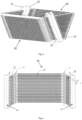
Fig. 2 is a schematic diagram of a heat exchanger according to a first embodiment of the present invention; -
Fig. 3 is a schematic diagram of a heat exchange module according to the first embodiment of the present invention, comprising the heat exchanger shown inFig. 2 ; -
Fig. 4 is a schematic diagram of a heat exchanger according to a second embodiment forming not a part of the present invention; -
Fig. 5 is a schematic diagram of another heat exchanger according to the second embodiment; -
Fig. 6 is a schematic diagram of a heat exchange module according to the second embodiment, comprising the two heat exchangers ofFig. 4 andFig. 5 ; -
Fig. 7 is a schematic diagram of a heat exchange module according to a third embodiment forming not a part of the present invention; -
Fig. 8 is a schematic diagram of a heat exchange module according to a fourth embodiment forming not a part of the present invention; -
Fig. 9 is a schematic diagram of a heat exchanger according to a fifth embodiment forming not a part of the present invention; -
Fig. 10 is a schematic diagram according to a fifth embodiment forming not a part of the present invention, comprising the heat exchanger ofFig. 9 ; -
Fig. 11 is a schematic diagram of a heat exchange module according to a sixth embodiment forming not a part of the present invention. - The technical solution of the present invention is explained in further detail below by means of embodiments, in conjunction with
Figs. 1 - 11 . In this description, identical or similar drawing labels indicate identical or similar components. The following explanation of embodiments of the present invention with reference to the accompanying drawings is intended to explain the overall inventive concept of the present invention, and should not be interpreted as a limitation of the present invention. - As will be understood from the background art of the present invention, the key design point of the present invention lies in improvement of the heat exchange module used in the heat source unit in the document
WO 2011013672 . Specifically, since the pair of heat exchangers in that document are arranged in a substantially V-shaped form in a side view drawing, a substantially V-shaped space will be formed between bent parts of opposing air heat exchangers. Clearly, in the aforesaid document, the space between main body parts of the pair of heat exchangers that have been fitted together, and the space between their adjacent bent parts, both substantially form the same V-shape, in other words the included angles between them are the same, and are generally in the range of 30 - 90°. The final result is that the V-shaped space between the pair of heat exchangers is not used effectively. Since the included angle between them is large, the V-shaped space must be closed by a plate body that has been cut into a substantially V-shaped form, i.e. a shrouding plate, to prevent air or wind from passing through the V-shaped space and thereby affecting the heat exchange effect. - In the present invention, a heat exchanger, heat exchange module, heat exchange device and heat source unit are provided, which successfully resolve the shortcomings mentioned in the aforesaid document at least partially. Thus, the description below will focus on ways in which the present invention improves the heat exchanger, heat exchange module, heat exchange device and heat source unit. The arrangement of components in the heat source unit mentioned in the aforesaid document (such as a blower, a water drainage plate in communication with the heat exchange device, and a machine room which houses cooling cycle constituent parts other than the heat exchange device) may also be applied in the present invention, and therefore the aforesaid document may be referred to for a specific description of those components, which are not described in detail again here.
- It is clear from the aforesaid document that a conventional heat exchanger is generally rectangular, and requires a sheet metal element to close the V-shaped side. It must be explained here that although it is referred to as a V-shaped side in the aforesaid document, in actual manufacturing processes it is generally manufactured to have a substantially trapezoidal shape, as can be seen from the accompanying drawings of the present invention and the aforesaid document. Therefore, in the present invention it is referred to as a trapezoidal side, so as to better conform to the actual situation. The object of the present invention is to increase the heat exchange area, to meet different application and installation requirements. It can be seen from the following that in the present invention, the trapezoidal sides closed by sheet metal elements are at least partially replaced by bending the heat exchangers such that after being joined together, the sides of the heat exchange module form a trapezoidal or substantially trapezoidal shape.
- The heat exchanger, heat exchange module, heat exchange device and heat source unit according to an embodiment of the present invention may be applied to a commercial air conditioning system, specifically used in a heat source unit, an air-cooled water chiller unit or a commercial rooftop machine. In general, the heat exchange device comprises at least one heat exchange module, which has at least one substantially trapezoidal side (abbreviated as trapezoidal heat exchange side part hereinbelow) perpendicular to left and right sides, wherein a header and heat exchange tubes and/or fins thereon are provided in a heat exchange side.
- Those skilled in the art will understand that when the heat exchange device has multiple
heat exchange modules 100, the heat exchange device may be formed of multipleheat exchange modules 100 of the same type, or employ any combination ofheat exchange modules 100 of different types according to the present invention, as required. - Referring to
Fig. 1 , a top end of theheat exchange module 100 is provided with atop plate 50, and a blower module orunit 30 is provided on thetop plate 50 in a position corresponding to theheat exchangers 1 and 2. In one embodiment, a cylindrical wind outlet 31 is provided in a direction of upward protrusion from thetop plate 50, and afan shroud 32 covers a protruding end face of the wind outlet 31. Theblower 30 comprises: a propeller-type fan, accommodated in the wind outlet 31; a shaft core, mounted in opposition to thefan shroud 32, and a fan motor, with the propeller-type fan being mounted on a rotation shaft. - Of course, in order to fix the
heat exchange module 100 in place better, the bottom of theheat exchange module 100 may also be provided with a supporting element or supporting frame (not shown) which fixes it in place. In practice, asFig. 1 shows, the left and right sides of theheat exchange module 100 are not V-shaped sides in a strict sense, but trapezoidal sides in practical applications. As shown in the figure, eachheat exchange module 100 has, on both the left and the right side in the plane of the page, a trapezoidal heat exchange side with an included angle θ between two non-parallel edges. - Here, to facilitate description and explanation, only a heat exchange part or heat exchanger/heat exchange unit contained therein is shown.
- Reference is made to
Figs. 2 - 3 , which show schematic diagrams of a heat exchanger according to a first embodiment of the present invention and a heat exchange module formed therefrom. Specifically referring toFig. 3 , theheat exchange module 100 comprises aheat exchange unit 10 and aheat exchange unit 20 which have been bent; as stated below, theheat exchange unit 10 andheat exchange unit 20 may be the same or different. Eachheat exchange unit heat exchangers - Referring to
Fig. 2 , in a first embodiment of the present invention, theheat exchanger 10 comprises aheader 11, aheader 12, heat exchange tubes 13 and fins 14. Multiple heat exchange tubes extending horizontally in a left-right direction in the plane of the page inFig. 2 (and the fins, if provided) form a main body part 15 of theheat exchanger 10, while multiple heat exchange tubes and fins disposed on two sides of theheat exchanger 10 at an angle α relative to the left-right direction in the plane of the page inFig. 2 form abent part 16 and a bent part 17. Thebent part 16 has a substantially trapezoidal side, for forming part of a trapezoidal heat exchange side (which will be described below) of the heat exchange module; the bent part 17 has a substantially quadrilateral side (shown in the figure as a parallelogram), for forming part of another trapezoidal heat exchange side of the heat exchange module. The main body part 15 andbent part 16 are connected at a straight line Y, which is called a bending axis Y due to the fact that, as described below, thebent part 16 is bent outwards relative to the plane of the page inFig. 2 , using the bending axis Y as an axis. By the same principle, the main body part 15 and bent part 17 are connected at a straight line Y'; Y and Y' are called bending axes due to the fact that, as described below, thebent parts 16 and 17 are bent outwards relative to the plane of the page inFig. 2 , using the bending axes Y and Y' as axes. It must be explained that in this example, thebent parts 16 and 17 are only bent once along the bending axes Y and Y' thereof. - In the
heat exchanger 10 shown inFig. 2 , theheaders heat exchanger 10, i.e. at the right side of thebent part 16 and the left side of the bent part 17. The lengths of theheader 11 and theheader 12 are equal or approximately equal, but as shown in the figure, they form a certain angle or are inclined relative to one another. Multiple heat exchange tubes 13 are disposed at intervals, parallel to each other, between theheader 11 and theheader 12. Multiple slots for fitting the heat exchange tubes 13 are provided on theheaders - Two sides of the heat exchange tubes 13 are bent at an angle α for example, using the width direction as an axis, wherein the points at which the heat exchange tubes are bent lie substantially on the bending axes Y and Y' respectively, and the angle α is in the range of β/2 - 5° to β/2 + 5°, wherein β is equal to or smaller than the included angle θ of the trapezoidal heat exchange side. By the same principle, the
heat exchanger 20 may be arranged in a similar manner to theheat exchanger 10, so as to be the same as theheat exchanger 10, and is not described here. - In order to focus on describing the important points, the figure omits the related components in a water chiller unit or heat source unit associated therewith. In view of the fact that the main design of the present invention relates to the heat exchange device, such an omission will not affect the understanding of the present invention by those skilled in the art, and will not result in the disclosed content of the present invention being incomplete.
- It is well known in the art that a heat exchange device comprises at least one heat exchange module. It can be understood that the heat exchange device according to the present invention may comprise one or more (e.g. two, three, five) heat exchange modules and a corresponding number of blower modules or blower units, wherein the multiple blower modules or blower units form a blower apparatus or blower system. Of course, each blower unit or module may also be one blower or a greater number of blowers.
- In general, the heat exchange module comprises two heat exchangers joined together. Of course, those skilled in the art will understand that the way in which the heat exchange module is formed is not limited to the type described above; the heat exchange module may also be formed in the following ways: the heat exchange module may comprise a single heat exchange unit, with trapezoidal heat exchange sides thereof being formed by bending a part of the single heat exchange unit (e.g. bending two ends of a single flat-plate heat exchanger). Alternatively, the heat exchange module may also be formed of multiple heat exchange units, wherein the trapezoidal heat exchange side part is formed by a single heat exchange unit, the trapezoidal heat exchange side being fitted onto another part (e.g. another heat exchanger adjacent thereto) of the heat exchange module. Alternatively, the heat exchange module may also comprise one heat exchange unit and one support member (e.g. a metal plate support member) which are fitted together facing each other, with the heat exchange unit being bent to form the trapezoidal heat exchange side, and the trapezoidal heat exchange side being fitted onto the support member. In principle, each heat exchange unit is a single heat exchanger in the conventional sense, i.e. has two headers, and multiple heat exchange tubes (e.g. flat tubes, on which multiple fins may be disposed if possible) extending in parallel at intervals therebetween. Of course, multiple heat exchangers may also be included. To make the description concise, a single heat exchange unit is abbreviated as a heat exchanger below.
- As shown in
Figs. 2 - 3 , in a first embodiment of the present invention, each heat exchange module comprises two identical heat exchangers, i.e. theheat exchangers - Specifically, the heat exchange tubes 13 in the
bent parts 16 and 17 are inclined and bent relative to the heat exchange tubes in the main body part 15, such that the plane in which the main body part 15 lies is perpendicular or substantially perpendicular to the plane in which each of the two bent parts lies. - Taking
Fig. 2 as an example, the method of bending theheat exchanger 10 having bent parts at two sides is explained as follows: first the flat tubes 13 are bent, then a body of theheat exchanger 10 is bent. The specific bending steps are as follows: first of all, two sides of each flat tube 13 (such as the left and right sides of the flat tube in the drawing) are bent at an angle α using the width direction of the flat tube (i.e. the front-rear direction in the plane of the page) as an axis, and the bent flat tubes 13 are then inserted into the slots (not shown) in theheaders Fig. 2 . Thus theheat exchanger 10 forms the main body part 15 andbent parts 16 and 17. Fins 14 are inserted between adjacent flat tubes, which are then put into a brazing furnace and brazed to form a single body. Finally, thebent parts 16 and 17 in the bent heat exchanger are bent along a direction substantially perpendicular to the main body part 15 using the bending axes Y and Y' as a bending axes (i.e. the body of the heat exchanger is bent), such that the main body part 15 is perpendicular or substantially perpendicular to thebent parts 16 and 17 (seeFig. 3 ). - As shown in
Figs. 2 and3 , the main body part 15 is a rectangular side in theheat exchange module 100, while thebent parts 16 and 17 of theheat exchanger 10 respectively form a trapezoidal heat exchange side of theheat exchange module 100 together with two bent parts of theother heat exchanger 20. However, it can be understood that the case where the main body part 15 is of rectangular shape is just one example; it may have any suitable shape as required, for example a substantially square, trapezoidal, or parallelogram shape. - In the
bent part 16, the bottommost flat tube has the shortest length, the topmost flat tube has the longest length, and the spacing between flat tubes is L. Moreover, preferably, the lengths of the flat tubes in the bent part increase incrementally by 2Ltgα from bottom to top. For convenience of fabrication, the length of each flat tube can be adjusted slightly. - During bending, preferably, the bending angle α of the flat tubes is substantially half of the included angle β between two non-parallel edges of the trapezoidal side (i.e. the bent part 16), but generally only needs to be in the range of β/2 - 5° to β/2 + 5°. The included angle β between the bending axis Y and the
header 12 is preferably substantially equal to or smaller than an apex angle θ of the heat exchange trapezoidal side. Of course, the manner of bending described above is merely an example of the present invention; those skilled in the art could of course choose another manner of bending as required (for example perform bending at a different angle). - For convenience of assembly, that end of the flat tube 13 which is located at the
header header 12 perpendicularly or substantially perpendicularly. Of course, those skilled in the art may also arrange for substantially or essentially no fins to be provided at the bending points of the flat tube 13 (i.e. substantially the locations of the bending axes Y and Y'), so that it is easier to bend theheat exchanger 10, and the bending radius can be made as small as possible. - Those skilled in the art will understand that in this embodiment, since the right-
side heat exchanger 10 and left-side heat exchanger 20 in theheat exchange module 100 are substantially identical or symmetric, the structure and bending principles of theheat exchanger 20 are substantially the same as the structure and principles of theheat exchanger 10, so are not described again here. - Referring to
Fig. 3 again, theheat exchanger 10 andheat exchanger 20 are connected to each other by means of their respective headers, to form theheat exchange module 100. That is, theheader 11 in theheat exchanger 10 is connected to aheader 22 in theheat exchanger 20, and theheader 12 in theheat exchanger 10 is connected to aheader 21 in theheat exchanger 20, such that the bent parts of theheat exchanger 10 and theheat exchanger 20 are used as two trapezoidal heat exchange sides of theheat exchange module 100 respectively, so the heat exchange area is increased. Those skilled in the art may select a particular arrangement as required, without being limited to the arrangement described above. The above examples are merely given to provide a demonstrative explanation, and cannot be interpreted as being a limitation of the present invention. - Reference is made to
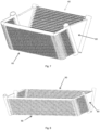
Figs. 4-6 , which show a heat exchange module according to a second embodiment forming not a part of the present invention; this heat exchange module is formed of twoasymmetric heat exchangers heat exchanger 60 has a rectangularmain body part 65 and twobent parts 66 and 67 which are substantially parallelogram-shaped. In the twobent parts 66 and 67, the lengths of the flat tubes are the same. The bending steps thereof are the same as in the first embodiment, the only difference being that two parallelogram-shaped bent parts are formed by bending. For this reason, a simple description of the bending steps is provided. - The bending steps of the
heat exchanger 60 are described concisely below:
First of all, the flat tubes are bent, then a core body of theheat exchanger 60 is bent; before the core body of the heat exchanger is assembled, two sides of each flat tube must each be bent at an angle α using the width direction as an axis. Preferably, α is substantially equal to half of an included angle β of a V-shape of a trapezoidal side; in thebent parts 66 and 67, each flat tube has the same length. However, for convenience of fabrication, the length of each flat tube can be adjusted slightly. - The
other heat exchanger 70 has a rectangularmain body part 75 and two substantially trapezoidalbent parts heat exchanger 70 are as follows:
First of all, the flat tubes are bent, then a core body of theheat exchanger 70 is bent; before the core body of the heat exchanger is assembled, two sides of each flat tube must each be bent at an angle α using the width direction as an axis. Preferably, α is substantially equal to half of an included angle β of a V-shape of a trapezoidal heat exchange side; in eachbent part heat exchanger 70, the length of each flat tube increases incrementally by 4L∗tgα from bottom to top. For convenience of fabrication, the length of each flat tube can be adjusted slightly. -
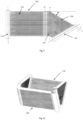
Fig. 7 shows a heat exchange module according to a third embodiment forming not a part of the present invention. The heat exchange module comprises twoasymmetric heat exchangers heat exchanger 60 is the same as theheat exchanger 60 inFig. 6 , and is therefore shown using the same reference labels (as below, so is not described again). - The
other heat exchanger 40 is a conventional heat exchanger, which only has a main body part that is identical or substantially identical to theheat exchanger 60. The difference is that two ends of the rectangular main body part are each provided with a header. - It can be understood that once the
heat exchangers element 80 shown inFig. 7 . The specific shape of theair baffle plate 80 and the material from which it is made, etc. may be selected according to requirements, and are not described in detail here. -
Fig. 8 shows a heat exchange module according to a fourth embodiment forming not a part of the present invention. The heat exchange module comprises twosymmetric heat exchangers 90. Theheat exchanger 90 differs from theheat exchanger 60 inFig. 6 only in that a bent part is provided on one side. The manner or steps of bending are the same as for theheat exchanger 60 inFig. 6 . - It can be understood that once the two
heat exchangers 90 have been joined together, there will be a triangular or substantially rectangular region with no heat exchange tubes or fins on each trapezoidal heat exchange side of the heat exchange module. Thus, this is called an air leakage region, and can be blocked with the air baffle plate or wind-blockingelement 80 shown inFig. 8 . The specific shape of theair baffle plate 80 and the material from which it is made, etc. may be selected according to requirements, and are not described in detail here. -
Figs. 9 and 10 show a heat exchange module and a heat exchanger according to a fifth embodiment forming not a part of the present invention. The heat exchange module comprises twoidentical heat exchangers 110. Reference is specifically made toFig. 9 , which shows the specific structure of theheat exchanger 110. Although theheat exchanger 110 has a bent part on only one side, it is formed by bending a core body of theheat exchanger 110 twice along two different bending axes Y and Y". - The specific bending steps and manner of bending are as follows:
First of all, one side of each flat tube (such as the right side of the flat tube in the drawing) is bent at an angle α using the width direction of the flat tube (i.e. the top-bottom direction in the plane of the page) as an axis, and the bent flat tubes are then inserted in sequence into slots (not shown) inheaders Fig. 9 . Thus theheat exchanger 110 forms amain body part 115 and abent part 116. Fins are inserted between adjacent flat tubes, which are then put into a brazing furnace and brazed to form a single body. Finally, thebent part 116 in the bent heat exchanger is bent along a direction substantially perpendicular to themain body part 115 using the bending axis Y as a bending axis (i.e. the body of the heat exchanger is bent); next, thebent part 116 is bent along the other bending axis Y" through a predetermined angle relative to themain body part 115, forming anotherbent part 117, such that themain body part 115 is perpendicular or substantially perpendicular to the bending part 116 (seeFig. 10 ). - The bending axis Y" may deviate from the axis Y, and may be on either side of the bending axis Y Preferably, the distance between Y" and Y is less than or equal to 200 mm. If an air leakage region is formed when the two
heat exchangers 110 are joined together, an air baffle plate may be disposed at the air leakage region. -
Fig. 11 shows a heat exchange module according to a sixth embodiment forming not a part of the present invention. The heat exchange module is fourheat exchangers - Two
heat exchangers 120 amongst the four heat exchangers have the same dimensions and substantially quadrilateral sides; the other twoheat exchangers 130 amongst the four heat exchangers have the same dimensions and trapezoidal sides. Eachheat exchanger - The advantage of the present invention is that it can increase the heat exchange area of the heat exchange device without increasing the size of the HVAC system. It can increase the energy efficiency of the HVAC system (decrease the power consumption) by improving the heat exchange performance of the heat exchanger. If the HVAC does not require higher energy efficiency and greater heat exchange performance, the present invention can also be used to reduce the number of heat exchangers in the system, such that the entire HVAC system is more compact, and has lower manufacturing and installation costs.
Claims (10)
- A heat exchanger (10) of a heat exchange device (100) for use on an air-cooled water chiller unit or commercial rooftop machine, wherein the heat exchanger (10) comprises:a main body part (15, 65), having a substantially quadrilateral side;two bent parts (16, 17; 66, 67) connected to the main body part (15);at least one heat exchange tube (13), extending between the main body part (15, 65) and both bent parts (16, 17; 66, 67), wherein at least one heat exchange tube (13) in the bent parts (16, 17; 66, 67) is inclined and bent relative to a heat exchange tube (13) in the main body part (15), such that the plane in which the main body part (15) lies is perpendicular or substantially perpendicular to the planes in which the bent parts (16, 17; 66, 67) lie, wherein one of the two bent parts (17; 66, 67) has a substantially trapezoidal side comprising two non-parallel sides,characterized bythe other bent part having a substantially parallelogram-shaped side.
- The heat exchanger as claimed in claim 1, characterized in that the heat exchange tube (13) is a flat tube andtwo sides of the heat exchange tube (13) are each bent at an angle α using a width direction of the flat tube as an axis, with a bending point on each side of the heat exchange tube (13) lying substantially on a first bending axis (y), and the heat exchange tube being bent at an angle β along the first bending axis,wherein β is the included angle between two non-parallel sides of a trapezoidal side, the angle α is in the range of β/2 - 5° to β/2 + 5°, and when a short edge of the trapezoidal side is located at the bottom, the length of each heat exchange tube increases incrementally by 2L*tgα from bottom to top, wherein the distance between heat exchange tubes in the bent part is L.
- The heat exchanger as claimed in claim 1, characterized in that
one side of the heat exchange tube (13) is bent using a width direction as an axis, with a bending point on this side of the heat exchange tube (13) lying substantially on a first bending axis (Y), and the heat exchange tube (13) being bent along the first bending axis (Y). - The heat exchanger as claimed in any one of claims 1 - 3, characterized byalso comprising two headers (11, 12; 21, 22) disposed on two opposite sides of the heat exchanger,wherein the heat exchange tube (13) is multiple heat exchange tubes, which are arranged at intervals in the main body part and bent part and extend substantially parallel to each other in the main body part and bent part;each of the heat exchange tubes extends from one of the two headers (11, 12; 21, 22) to the other header through the bent part and main body part.
- The heat exchanger as claimed in claim 4, characterized in that
the heat exchange tubes (13) are flat tubes, and fins (14) are disposed on those parts of the flat tubes which are not bending points, with ends of the flat tubes being in perpendicular communication with the headers (11, 12; 21, 22). - A heat exchange module (100) of a heat exchange device for use on an air-cooled water chiller unit or commercial rooftop machine, the heat exchange device comprising at least one heat exchange module (100), each heat exchange module (100) comprising two identical and matching heat exchangers (10, 20) which are joined together, characterized in that each heat exchanger (10) is the heat exchanger (10) as claimed in claim 2.
- A heat exchange module of a heat exchange device for use on an air-cooled water chiller unit or commercial rooftop machine, the heat exchange device comprising at least one heat exchange module comprising two heat exchangers which are joined together, characterized in that each heat exchange module comprises two identical and matching heat exchangers, each of these two heat exchangers being the heat exchanger as claimed in claim 4.
- The heat exchange module as claimed in claim 7, characterized in that an air leakage region formed when the two heat exchangers are joined together is provided with an air baffle plate.
- A heat exchange device for use on an air-cooled water chiller unit or commercial rooftop machine, the heat exchange device comprising at least one heat exchange module which is the heat exchange module as claimed in any one of claims 6 - 8.
- A heat source unit, the heat source unit also comprising, in cooperation with each other, a heat exchange device, a blower, a water drainage plate in communication with the heat exchange device, and a machine room which houses cooling cycle constituent parts other than the heat exchange device, characterized in that the heat exchange device is the heat exchange device as claimed in claim 9.
Priority Applications (1)
| Application Number | Priority Date | Filing Date | Title |
|---|---|---|---|
| EP23159549.7A EP4209748B1 (en) | 2014-12-11 | 2015-10-28 | Heat exchanger, heat exchange module, heat exchanger device and heat source unit |
Applications Claiming Priority (2)
| Application Number | Priority Date | Filing Date | Title |
|---|---|---|---|
| CN201420783711.6U CN204329670U (en) | 2014-12-11 | 2014-12-11 | Heat exchanger, heat exchange module, heat-exchanger rig and heat source unit |
| PCT/CN2015/093042 WO2016091021A1 (en) | 2014-12-11 | 2015-10-28 | Heat exchanger, heat exchange module, heat exchange device, and heat source unit |
Related Child Applications (2)
| Application Number | Title | Priority Date | Filing Date |
|---|---|---|---|
| EP23159549.7A Division EP4209748B1 (en) | 2014-12-11 | 2015-10-28 | Heat exchanger, heat exchange module, heat exchanger device and heat source unit |
| EP23159549.7A Division-Into EP4209748B1 (en) | 2014-12-11 | 2015-10-28 | Heat exchanger, heat exchange module, heat exchanger device and heat source unit |
Publications (3)
| Publication Number | Publication Date |
|---|---|
| EP3232148A1 EP3232148A1 (en) | 2017-10-18 |
| EP3232148A4 EP3232148A4 (en) | 2018-07-11 |
| EP3232148B1 true EP3232148B1 (en) | 2023-05-10 |
Family
ID=53166021
Family Applications (2)
| Application Number | Title | Priority Date | Filing Date |
|---|---|---|---|
| EP23159549.7A Active EP4209748B1 (en) | 2014-12-11 | 2015-10-28 | Heat exchanger, heat exchange module, heat exchanger device and heat source unit |
| EP15866545.5A Active EP3232148B1 (en) | 2014-12-11 | 2015-10-28 | Heat exchanger, heat exchange module, heat exchange device, and heat source unit |
Family Applications Before (1)
| Application Number | Title | Priority Date | Filing Date |
|---|---|---|---|
| EP23159549.7A Active EP4209748B1 (en) | 2014-12-11 | 2015-10-28 | Heat exchanger, heat exchange module, heat exchanger device and heat source unit |
Country Status (5)
| Country | Link |
|---|---|
| US (1) | US10495326B2 (en) |
| EP (2) | EP4209748B1 (en) |
| JP (1) | JP6711813B2 (en) |
| CN (1) | CN204329670U (en) |
| WO (1) | WO2016091021A1 (en) |
Families Citing this family (15)
| Publication number | Priority date | Publication date | Assignee | Title |
|---|---|---|---|---|
| CN204329670U (en) * | 2014-12-11 | 2015-05-13 | 丹佛斯微通道换热器(嘉兴)有限公司 | Heat exchanger, heat exchange module, heat-exchanger rig and heat source unit |
| WO2016181560A1 (en) * | 2015-05-14 | 2016-11-17 | 三菱電機株式会社 | Outdoor unit for air conditioner |
| CN107388637B (en) * | 2016-05-16 | 2023-04-28 | 丹佛斯微通道换热器(嘉兴)有限公司 | Heat exchanger and heat exchange module |
| CN106196557B (en) * | 2016-07-04 | 2022-01-28 | 珠海格力电器股份有限公司 | Heat exchanger and air conditioner with same |
| CN107782018B (en) | 2016-08-26 | 2023-10-31 | 丹佛斯微通道换热器(嘉兴)有限公司 | Heat exchanger, heat exchanger module and air conditioning system |
| USD907752S1 (en) | 2016-08-26 | 2021-01-12 | Danfoss Micro Channel Heat Exchanger (Jiaxing) Co., Ltd. | Heat exchanger |
| JP6369518B2 (en) * | 2016-09-30 | 2018-08-08 | ダイキン工業株式会社 | Refrigeration equipment |
| US10900721B2 (en) * | 2016-10-07 | 2021-01-26 | Mitsubishi Electric Corporation | Heat exchanger and air-conditioning apparatus |
| CN106766388A (en) * | 2016-12-22 | 2017-05-31 | 刘勇 | Suitable for the outdoor heat exchanger and Cascade type heat pump system of extremely cold area |
| CN206905358U (en) * | 2017-06-29 | 2018-01-19 | 杭州三花家电热管理系统有限公司 | Heat exchanger and there is its heat exchanger assembly and refrigeration plant |
| JP1615399S (en) * | 2017-08-21 | 2018-10-09 | ||
| WO2020101934A1 (en) * | 2018-11-12 | 2020-05-22 | Carrier Corporation | Compact heat exchanger assembly for a refrigeration system |
| JPWO2021024408A1 (en) * | 2019-08-07 | 2021-02-11 | ||
| WO2021024403A1 (en) * | 2019-08-07 | 2021-02-11 | 三菱電機株式会社 | Chilling unit |
| CN210688491U (en) * | 2019-09-06 | 2020-06-05 | 广东美的制冷设备有限公司 | Heat exchanger and air conditioner with same |
Citations (1)
| Publication number | Priority date | Publication date | Assignee | Title |
|---|---|---|---|---|
| EP1832833A2 (en) * | 2006-03-06 | 2007-09-12 | Delphi Technologies, Inc. | Heat exchanger unit |
Family Cites Families (14)
| Publication number | Priority date | Publication date | Assignee | Title |
|---|---|---|---|---|
| US4261418A (en) * | 1979-12-12 | 1981-04-14 | Westinghouse Electric Corp. | Outdoor coil unit for heat pump |
| JP3736514B2 (en) * | 2002-09-13 | 2006-01-18 | 三菱電機株式会社 | Heat exchanger and air conditioner using heat exchanger |
| JP4417620B2 (en) | 2002-10-25 | 2010-02-17 | 東芝キヤリア株式会社 | Heat exchanger for air conditioner |
| JP2004340504A (en) * | 2003-05-16 | 2004-12-02 | Mitsubishi Heavy Ind Ltd | Outdoor unit for air conditioning and air conditioner comprising the same |
| JP2005300017A (en) * | 2004-04-12 | 2005-10-27 | Calsonic Kansei Corp | Heat exchanger and manufacturing method thereof |
| TWM262527U (en) | 2004-09-22 | 2005-04-21 | Chiou-Niu Linshie | Stand for RC steel wall/partition wall |
| KR20100015374A (en) * | 2007-04-05 | 2010-02-12 | 존슨 컨트롤스 테크놀러지 컴퍼니 | Heat exchanger |
| US20090084131A1 (en) | 2007-10-01 | 2009-04-02 | Nordyne Inc. | Air Conditioning Units with Modular Heat Exchangers, Inventories, Buildings, and Methods |
| US20110094257A1 (en) | 2008-03-20 | 2011-04-28 | Carrier Corporation | Micro-channel heat exchanger suitable for bending |
| KR101381447B1 (en) | 2009-07-28 | 2014-04-04 | 도시바 캐리어 가부시키가이샤 | Heat source unit |
| JP5308275B2 (en) * | 2009-08-24 | 2013-10-09 | 国立大学法人東京工業大学 | Sunlight collection system |
| EP2478318A4 (en) | 2009-09-16 | 2014-05-28 | Carrier Corp | Free-draining finned surface architecture for a heat exchanger |
| CN103925742B (en) * | 2014-04-18 | 2016-06-29 | 丹佛斯微通道换热器(嘉兴)有限公司 | Heat exchanger and manufacture method, heat exchange module, heat-exchanger rig and heat source unit |
| CN204329670U (en) * | 2014-12-11 | 2015-05-13 | 丹佛斯微通道换热器(嘉兴)有限公司 | Heat exchanger, heat exchange module, heat-exchanger rig and heat source unit |
-
2014
- 2014-12-11 CN CN201420783711.6U patent/CN204329670U/en active Active
-
2015
- 2015-10-28 EP EP23159549.7A patent/EP4209748B1/en active Active
- 2015-10-28 EP EP15866545.5A patent/EP3232148B1/en active Active
- 2015-10-28 JP JP2017502170A patent/JP6711813B2/en active Active
- 2015-10-28 WO PCT/CN2015/093042 patent/WO2016091021A1/en active Application Filing
- 2015-10-28 US US15/323,988 patent/US10495326B2/en active Active
Patent Citations (1)
| Publication number | Priority date | Publication date | Assignee | Title |
|---|---|---|---|---|
| EP1832833A2 (en) * | 2006-03-06 | 2007-09-12 | Delphi Technologies, Inc. | Heat exchanger unit |
Also Published As
| Publication number | Publication date |
|---|---|
| EP4209748B1 (en) | 2024-08-21 |
| WO2016091021A1 (en) | 2016-06-16 |
| JP6711813B2 (en) | 2020-06-17 |
| EP4209748A1 (en) | 2023-07-12 |
| EP3232148A1 (en) | 2017-10-18 |
| US10495326B2 (en) | 2019-12-03 |
| EP3232148A4 (en) | 2018-07-11 |
| JP2017537287A (en) | 2017-12-14 |
| US20170205085A1 (en) | 2017-07-20 |
| CN204329670U (en) | 2015-05-13 |
Similar Documents
| Publication | Publication Date | Title |
|---|---|---|
| EP3232148B1 (en) | Heat exchanger, heat exchange module, heat exchange device, and heat source unit | |
| US10429134B2 (en) | Heat exchanger and manufacturing method therefor, heat exchange module, heat exchange device, and heat source unit | |
| WO2016091026A1 (en) | Heat exchanger, heat exchanging module, heat exchanging device and heat source unit | |
| KR102411030B1 (en) | Heat exchanger apparatus and heat source unit | |
| EP2930456B1 (en) | Flat tube heat exchange apparatus, and outdoor unit for air conditioner provided with same | |
| WO2016171177A1 (en) | Heat source unit | |
| WO2020062722A1 (en) | Fin and heat exchanger having same | |
| CN107906729B (en) | Heat exchange device and air conditioning equipment | |
| JP2014077612A (en) | Indoor unit of air conditioner | |
| CN211739303U (en) | Air conditioner outdoor unit and air conditioner | |
| JP7155538B2 (en) | Heat exchanger | |
| JP7006376B2 (en) | Heat exchanger | |
| JP2012154520A (en) | Tube for heat exchanger, and heat exchanger | |
| JP2008032264A (en) | Heat exchanger | |
| JP2015010754A (en) | Heat exchanger and air conditioner including the same | |
| JP2016003795A (en) | Fin tube-type heat exchanger and its manufacturing method |
Legal Events
| Date | Code | Title | Description |
|---|---|---|---|
| STAA | Information on the status of an ep patent application or granted ep patent |
Free format text: STATUS: THE INTERNATIONAL PUBLICATION HAS BEEN MADE |
|
| PUAI | Public reference made under article 153(3) epc to a published international application that has entered the european phase |
Free format text: ORIGINAL CODE: 0009012 |
|
| STAA | Information on the status of an ep patent application or granted ep patent |
Free format text: STATUS: REQUEST FOR EXAMINATION WAS MADE |
|
| 17P | Request for examination filed |
Effective date: 20170125 |
|
| AK | Designated contracting states |
Kind code of ref document: A1 Designated state(s): AL AT BE BG CH CY CZ DE DK EE ES FI FR GB GR HR HU IE IS IT LI LT LU LV MC MK MT NL NO PL PT RO RS SE SI SK SM TR |
|
| AX | Request for extension of the european patent |
Extension state: BA ME |
|
| DAV | Request for validation of the european patent (deleted) | ||
| DAX | Request for extension of the european patent (deleted) | ||
| A4 | Supplementary search report drawn up and despatched |
Effective date: 20180612 |
|
| RIC1 | Information provided on ipc code assigned before grant |
Ipc: F24F 13/30 20060101ALI20180606BHEP Ipc: F28D 1/04 20060101AFI20180606BHEP Ipc: F25B 39/00 20060101ALI20180606BHEP Ipc: F28F 1/22 20060101ALI20180606BHEP |
|
| STAA | Information on the status of an ep patent application or granted ep patent |
Free format text: STATUS: EXAMINATION IS IN PROGRESS |
|
| 17Q | First examination report despatched |
Effective date: 20200313 |
|
| STAA | Information on the status of an ep patent application or granted ep patent |
Free format text: STATUS: EXAMINATION IS IN PROGRESS |
|
| STAA | Information on the status of an ep patent application or granted ep patent |
Free format text: STATUS: EXAMINATION IS IN PROGRESS |
|
| RIC1 | Information provided on ipc code assigned before grant |
Ipc: F28F 9/02 20060101ALI20220222BHEP Ipc: F28D 1/047 20060101ALI20220222BHEP Ipc: F28D 1/02 20060101ALI20220222BHEP Ipc: F25B 39/04 20060101ALI20220222BHEP Ipc: F24F 13/30 20060101ALI20220222BHEP Ipc: F28F 1/22 20060101ALI20220222BHEP Ipc: F25B 39/00 20060101ALI20220222BHEP Ipc: F28D 1/04 20060101AFI20220222BHEP |
|
| GRAP | Despatch of communication of intention to grant a patent |
Free format text: ORIGINAL CODE: EPIDOSNIGR1 |
|
| STAA | Information on the status of an ep patent application or granted ep patent |
Free format text: STATUS: GRANT OF PATENT IS INTENDED |
|
| INTG | Intention to grant announced |
Effective date: 20230112 |
|
| GRAS | Grant fee paid |
Free format text: ORIGINAL CODE: EPIDOSNIGR3 |
|
| GRAA | (expected) grant |
Free format text: ORIGINAL CODE: 0009210 |
|
| STAA | Information on the status of an ep patent application or granted ep patent |
Free format text: STATUS: THE PATENT HAS BEEN GRANTED |
|
| AK | Designated contracting states |
Kind code of ref document: B1 Designated state(s): AL AT BE BG CH CY CZ DE DK EE ES FI FR GB GR HR HU IE IS IT LI LT LU LV MC MK MT NL NO PL PT RO RS SE SI SK SM TR |
|
| REG | Reference to a national code |
Ref country code: GB Ref legal event code: FG4D |
|
| REG | Reference to a national code |
Ref country code: AT Ref legal event code: REF Ref document number: 1567048 Country of ref document: AT Kind code of ref document: T Effective date: 20230515 Ref country code: CH Ref legal event code: EP |
|
| REG | Reference to a national code |
Ref country code: DE Ref legal event code: R096 Ref document number: 602015083565 Country of ref document: DE |
|
| REG | Reference to a national code |
Ref country code: IE Ref legal event code: FG4D |
|
| REG | Reference to a national code |
Ref country code: LT Ref legal event code: MG9D |
|
| REG | Reference to a national code |
Ref country code: NL Ref legal event code: MP Effective date: 20230510 |
|
| REG | Reference to a national code |
Ref country code: AT Ref legal event code: MK05 Ref document number: 1567048 Country of ref document: AT Kind code of ref document: T Effective date: 20230510 |
|
| PG25 | Lapsed in a contracting state [announced via postgrant information from national office to epo] |
Ref country code: SE Free format text: LAPSE BECAUSE OF FAILURE TO SUBMIT A TRANSLATION OF THE DESCRIPTION OR TO PAY THE FEE WITHIN THE PRESCRIBED TIME-LIMIT Effective date: 20230510 Ref country code: PT Free format text: LAPSE BECAUSE OF FAILURE TO SUBMIT A TRANSLATION OF THE DESCRIPTION OR TO PAY THE FEE WITHIN THE PRESCRIBED TIME-LIMIT Effective date: 20230911 Ref country code: NO Free format text: LAPSE BECAUSE OF FAILURE TO SUBMIT A TRANSLATION OF THE DESCRIPTION OR TO PAY THE FEE WITHIN THE PRESCRIBED TIME-LIMIT Effective date: 20230810 Ref country code: NL Free format text: LAPSE BECAUSE OF FAILURE TO SUBMIT A TRANSLATION OF THE DESCRIPTION OR TO PAY THE FEE WITHIN THE PRESCRIBED TIME-LIMIT Effective date: 20230510 Ref country code: ES Free format text: LAPSE BECAUSE OF FAILURE TO SUBMIT A TRANSLATION OF THE DESCRIPTION OR TO PAY THE FEE WITHIN THE PRESCRIBED TIME-LIMIT Effective date: 20230510 Ref country code: AT Free format text: LAPSE BECAUSE OF FAILURE TO SUBMIT A TRANSLATION OF THE DESCRIPTION OR TO PAY THE FEE WITHIN THE PRESCRIBED TIME-LIMIT Effective date: 20230510 |
|
| PGFP | Annual fee paid to national office [announced via postgrant information from national office to epo] |
Ref country code: IT Payment date: 20230913 Year of fee payment: 9 |
|
| PG25 | Lapsed in a contracting state [announced via postgrant information from national office to epo] |
Ref country code: RS Free format text: LAPSE BECAUSE OF FAILURE TO SUBMIT A TRANSLATION OF THE DESCRIPTION OR TO PAY THE FEE WITHIN THE PRESCRIBED TIME-LIMIT Effective date: 20230510 Ref country code: PL Free format text: LAPSE BECAUSE OF FAILURE TO SUBMIT A TRANSLATION OF THE DESCRIPTION OR TO PAY THE FEE WITHIN THE PRESCRIBED TIME-LIMIT Effective date: 20230510 Ref country code: LV Free format text: LAPSE BECAUSE OF FAILURE TO SUBMIT A TRANSLATION OF THE DESCRIPTION OR TO PAY THE FEE WITHIN THE PRESCRIBED TIME-LIMIT Effective date: 20230510 Ref country code: LT Free format text: LAPSE BECAUSE OF FAILURE TO SUBMIT A TRANSLATION OF THE DESCRIPTION OR TO PAY THE FEE WITHIN THE PRESCRIBED TIME-LIMIT Effective date: 20230510 Ref country code: IS Free format text: LAPSE BECAUSE OF FAILURE TO SUBMIT A TRANSLATION OF THE DESCRIPTION OR TO PAY THE FEE WITHIN THE PRESCRIBED TIME-LIMIT Effective date: 20230910 Ref country code: HR Free format text: LAPSE BECAUSE OF FAILURE TO SUBMIT A TRANSLATION OF THE DESCRIPTION OR TO PAY THE FEE WITHIN THE PRESCRIBED TIME-LIMIT Effective date: 20230510 Ref country code: GR Free format text: LAPSE BECAUSE OF FAILURE TO SUBMIT A TRANSLATION OF THE DESCRIPTION OR TO PAY THE FEE WITHIN THE PRESCRIBED TIME-LIMIT Effective date: 20230811 |
|
| PGFP | Annual fee paid to national office [announced via postgrant information from national office to epo] |
Ref country code: FR Payment date: 20230911 Year of fee payment: 9 |
|
| PG25 | Lapsed in a contracting state [announced via postgrant information from national office to epo] |
Ref country code: FI Free format text: LAPSE BECAUSE OF FAILURE TO SUBMIT A TRANSLATION OF THE DESCRIPTION OR TO PAY THE FEE WITHIN THE PRESCRIBED TIME-LIMIT Effective date: 20230510 |
|
| PG25 | Lapsed in a contracting state [announced via postgrant information from national office to epo] |
Ref country code: SK Free format text: LAPSE BECAUSE OF FAILURE TO SUBMIT A TRANSLATION OF THE DESCRIPTION OR TO PAY THE FEE WITHIN THE PRESCRIBED TIME-LIMIT Effective date: 20230510 |
|
| PG25 | Lapsed in a contracting state [announced via postgrant information from national office to epo] |
Ref country code: SM Free format text: LAPSE BECAUSE OF FAILURE TO SUBMIT A TRANSLATION OF THE DESCRIPTION OR TO PAY THE FEE WITHIN THE PRESCRIBED TIME-LIMIT Effective date: 20230510 Ref country code: SK Free format text: LAPSE BECAUSE OF FAILURE TO SUBMIT A TRANSLATION OF THE DESCRIPTION OR TO PAY THE FEE WITHIN THE PRESCRIBED TIME-LIMIT Effective date: 20230510 Ref country code: RO Free format text: LAPSE BECAUSE OF FAILURE TO SUBMIT A TRANSLATION OF THE DESCRIPTION OR TO PAY THE FEE WITHIN THE PRESCRIBED TIME-LIMIT Effective date: 20230510 Ref country code: EE Free format text: LAPSE BECAUSE OF FAILURE TO SUBMIT A TRANSLATION OF THE DESCRIPTION OR TO PAY THE FEE WITHIN THE PRESCRIBED TIME-LIMIT Effective date: 20230510 Ref country code: DK Free format text: LAPSE BECAUSE OF FAILURE TO SUBMIT A TRANSLATION OF THE DESCRIPTION OR TO PAY THE FEE WITHIN THE PRESCRIBED TIME-LIMIT Effective date: 20230510 Ref country code: CZ Free format text: LAPSE BECAUSE OF FAILURE TO SUBMIT A TRANSLATION OF THE DESCRIPTION OR TO PAY THE FEE WITHIN THE PRESCRIBED TIME-LIMIT Effective date: 20230510 |
|
| REG | Reference to a national code |
Ref country code: DE Ref legal event code: R097 Ref document number: 602015083565 Country of ref document: DE |
|
| PLBE | No opposition filed within time limit |
Free format text: ORIGINAL CODE: 0009261 |
|
| STAA | Information on the status of an ep patent application or granted ep patent |
Free format text: STATUS: NO OPPOSITION FILED WITHIN TIME LIMIT |
|
| 26N | No opposition filed |
Effective date: 20240213 |
|
| REG | Reference to a national code |
Ref country code: DE Ref legal event code: R119 Ref document number: 602015083565 Country of ref document: DE |
|
| PG25 | Lapsed in a contracting state [announced via postgrant information from national office to epo] |
Ref country code: SI Free format text: LAPSE BECAUSE OF FAILURE TO SUBMIT A TRANSLATION OF THE DESCRIPTION OR TO PAY THE FEE WITHIN THE PRESCRIBED TIME-LIMIT Effective date: 20230510 |
|
| PG25 | Lapsed in a contracting state [announced via postgrant information from national office to epo] |
Ref country code: SI Free format text: LAPSE BECAUSE OF FAILURE TO SUBMIT A TRANSLATION OF THE DESCRIPTION OR TO PAY THE FEE WITHIN THE PRESCRIBED TIME-LIMIT Effective date: 20230510 Ref country code: MC Free format text: LAPSE BECAUSE OF FAILURE TO SUBMIT A TRANSLATION OF THE DESCRIPTION OR TO PAY THE FEE WITHIN THE PRESCRIBED TIME-LIMIT Effective date: 20230510 |
|
| REG | Reference to a national code |
Ref country code: CH Ref legal event code: PL |
|
| REG | Reference to a national code |
Ref country code: BE Ref legal event code: MM Effective date: 20231031 |
|
| PG25 | Lapsed in a contracting state [announced via postgrant information from national office to epo] |
Ref country code: LU Free format text: LAPSE BECAUSE OF NON-PAYMENT OF DUE FEES Effective date: 20231028 |
|
| GBPC | Gb: european patent ceased through non-payment of renewal fee |
Effective date: 20231028 |
|
| PG25 | Lapsed in a contracting state [announced via postgrant information from national office to epo] |
Ref country code: LU Free format text: LAPSE BECAUSE OF NON-PAYMENT OF DUE FEES Effective date: 20231028 |
|
| PG25 | Lapsed in a contracting state [announced via postgrant information from national office to epo] |
Ref country code: GB Free format text: LAPSE BECAUSE OF NON-PAYMENT OF DUE FEES Effective date: 20231028 |
|
| PG25 | Lapsed in a contracting state [announced via postgrant information from national office to epo] |
Ref country code: CH Free format text: LAPSE BECAUSE OF NON-PAYMENT OF DUE FEES Effective date: 20231031 |
|
| PG25 | Lapsed in a contracting state [announced via postgrant information from national office to epo] |
Ref country code: GB Free format text: LAPSE BECAUSE OF NON-PAYMENT OF DUE FEES Effective date: 20231028 Ref country code: DE Free format text: LAPSE BECAUSE OF NON-PAYMENT OF DUE FEES Effective date: 20240501 Ref country code: CH Free format text: LAPSE BECAUSE OF NON-PAYMENT OF DUE FEES Effective date: 20231031 |
|
| PG25 | Lapsed in a contracting state [announced via postgrant information from national office to epo] |
Ref country code: BE Free format text: LAPSE BECAUSE OF NON-PAYMENT OF DUE FEES Effective date: 20231031 |