EP3231585B1 - Device for ultrasonic welding - Google Patents
Device for ultrasonic welding Download PDFInfo
- Publication number
- EP3231585B1 EP3231585B1 EP17000493.1A EP17000493A EP3231585B1 EP 3231585 B1 EP3231585 B1 EP 3231585B1 EP 17000493 A EP17000493 A EP 17000493A EP 3231585 B1 EP3231585 B1 EP 3231585B1
- Authority
- EP
- European Patent Office
- Prior art keywords
- ultrasonic
- welding
- ultrasonic welding
- length
- welding unit
- Prior art date
- Legal status (The legal status is an assumption and is not a legal conclusion. Google has not performed a legal analysis and makes no representation as to the accuracy of the status listed.)
- Active
Links
Images


Classifications
-
- B—PERFORMING OPERATIONS; TRANSPORTING
- B29—WORKING OF PLASTICS; WORKING OF SUBSTANCES IN A PLASTIC STATE IN GENERAL
- B29C—SHAPING OR JOINING OF PLASTICS; SHAPING OF MATERIAL IN A PLASTIC STATE, NOT OTHERWISE PROVIDED FOR; AFTER-TREATMENT OF THE SHAPED PRODUCTS, e.g. REPAIRING
- B29C65/00—Joining or sealing of preformed parts, e.g. welding of plastics materials; Apparatus therefor
- B29C65/02—Joining or sealing of preformed parts, e.g. welding of plastics materials; Apparatus therefor by heating, with or without pressure
- B29C65/08—Joining or sealing of preformed parts, e.g. welding of plastics materials; Apparatus therefor by heating, with or without pressure using ultrasonic vibrations
-
- B—PERFORMING OPERATIONS; TRANSPORTING
- B29—WORKING OF PLASTICS; WORKING OF SUBSTANCES IN A PLASTIC STATE IN GENERAL
- B29C—SHAPING OR JOINING OF PLASTICS; SHAPING OF MATERIAL IN A PLASTIC STATE, NOT OTHERWISE PROVIDED FOR; AFTER-TREATMENT OF THE SHAPED PRODUCTS, e.g. REPAIRING
- B29C66/00—General aspects of processes or apparatus for joining preformed parts
- B29C66/01—General aspects dealing with the joint area or with the area to be joined
- B29C66/05—Particular design of joint configurations
- B29C66/10—Particular design of joint configurations particular design of the joint cross-sections
- B29C66/11—Joint cross-sections comprising a single joint-segment, i.e. one of the parts to be joined comprising a single joint-segment in the joint cross-section
- B29C66/112—Single lapped joints
- B29C66/1122—Single lap to lap joints, i.e. overlap joints
-
- B—PERFORMING OPERATIONS; TRANSPORTING
- B29—WORKING OF PLASTICS; WORKING OF SUBSTANCES IN A PLASTIC STATE IN GENERAL
- B29C—SHAPING OR JOINING OF PLASTICS; SHAPING OF MATERIAL IN A PLASTIC STATE, NOT OTHERWISE PROVIDED FOR; AFTER-TREATMENT OF THE SHAPED PRODUCTS, e.g. REPAIRING
- B29C66/00—General aspects of processes or apparatus for joining preformed parts
- B29C66/40—General aspects of joining substantially flat articles, e.g. plates, sheets or web-like materials; Making flat seams in tubular or hollow articles; Joining single elements to substantially flat surfaces
- B29C66/41—Joining substantially flat articles ; Making flat seams in tubular or hollow articles
- B29C66/43—Joining a relatively small portion of the surface of said articles
- B29C66/431—Joining the articles to themselves
-
- B—PERFORMING OPERATIONS; TRANSPORTING
- B29—WORKING OF PLASTICS; WORKING OF SUBSTANCES IN A PLASTIC STATE IN GENERAL
- B29C—SHAPING OR JOINING OF PLASTICS; SHAPING OF MATERIAL IN A PLASTIC STATE, NOT OTHERWISE PROVIDED FOR; AFTER-TREATMENT OF THE SHAPED PRODUCTS, e.g. REPAIRING
- B29C66/00—General aspects of processes or apparatus for joining preformed parts
- B29C66/80—General aspects of machine operations or constructions and parts thereof
- B29C66/81—General aspects of the pressing elements, i.e. the elements applying pressure on the parts to be joined in the area to be joined, e.g. the welding jaws or clamps
- B29C66/816—General aspects of the pressing elements, i.e. the elements applying pressure on the parts to be joined in the area to be joined, e.g. the welding jaws or clamps characterised by the mounting of the pressing elements, e.g. of the welding jaws or clamps
- B29C66/8163—Self-aligning to the joining plane, e.g. mounted on a ball and socket
-
- B—PERFORMING OPERATIONS; TRANSPORTING
- B29—WORKING OF PLASTICS; WORKING OF SUBSTANCES IN A PLASTIC STATE IN GENERAL
- B29C—SHAPING OR JOINING OF PLASTICS; SHAPING OF MATERIAL IN A PLASTIC STATE, NOT OTHERWISE PROVIDED FOR; AFTER-TREATMENT OF THE SHAPED PRODUCTS, e.g. REPAIRING
- B29C66/00—General aspects of processes or apparatus for joining preformed parts
- B29C66/80—General aspects of machine operations or constructions and parts thereof
- B29C66/81—General aspects of the pressing elements, i.e. the elements applying pressure on the parts to be joined in the area to be joined, e.g. the welding jaws or clamps
- B29C66/816—General aspects of the pressing elements, i.e. the elements applying pressure on the parts to be joined in the area to be joined, e.g. the welding jaws or clamps characterised by the mounting of the pressing elements, e.g. of the welding jaws or clamps
- B29C66/8167—Quick change joining tools or surfaces
-
- B—PERFORMING OPERATIONS; TRANSPORTING
- B29—WORKING OF PLASTICS; WORKING OF SUBSTANCES IN A PLASTIC STATE IN GENERAL
- B29C—SHAPING OR JOINING OF PLASTICS; SHAPING OF MATERIAL IN A PLASTIC STATE, NOT OTHERWISE PROVIDED FOR; AFTER-TREATMENT OF THE SHAPED PRODUCTS, e.g. REPAIRING
- B29C66/00—General aspects of processes or apparatus for joining preformed parts
- B29C66/80—General aspects of machine operations or constructions and parts thereof
- B29C66/81—General aspects of the pressing elements, i.e. the elements applying pressure on the parts to be joined in the area to be joined, e.g. the welding jaws or clamps
- B29C66/818—General aspects of the pressing elements, i.e. the elements applying pressure on the parts to be joined in the area to be joined, e.g. the welding jaws or clamps characterised by the cooling constructional aspects, or by the thermal or electrical insulating or conducting constructional aspects of the welding jaws or of the clamps ; comprising means for compensating for the thermal expansion of the welding jaws or of the clamps
- B29C66/8181—General aspects of the pressing elements, i.e. the elements applying pressure on the parts to be joined in the area to be joined, e.g. the welding jaws or clamps characterised by the cooling constructional aspects, or by the thermal or electrical insulating or conducting constructional aspects of the welding jaws or of the clamps ; comprising means for compensating for the thermal expansion of the welding jaws or of the clamps characterised by the cooling constructional aspects
- B29C66/81811—General aspects of the pressing elements, i.e. the elements applying pressure on the parts to be joined in the area to be joined, e.g. the welding jaws or clamps characterised by the cooling constructional aspects, or by the thermal or electrical insulating or conducting constructional aspects of the welding jaws or of the clamps ; comprising means for compensating for the thermal expansion of the welding jaws or of the clamps characterised by the cooling constructional aspects of the welding jaws
- B29C66/81812—General aspects of the pressing elements, i.e. the elements applying pressure on the parts to be joined in the area to be joined, e.g. the welding jaws or clamps characterised by the cooling constructional aspects, or by the thermal or electrical insulating or conducting constructional aspects of the welding jaws or of the clamps ; comprising means for compensating for the thermal expansion of the welding jaws or of the clamps characterised by the cooling constructional aspects of the welding jaws the welding jaws being cooled from the outside, e.g. by blowing a gas or spraying a liquid
-
- B—PERFORMING OPERATIONS; TRANSPORTING
- B29—WORKING OF PLASTICS; WORKING OF SUBSTANCES IN A PLASTIC STATE IN GENERAL
- B29C—SHAPING OR JOINING OF PLASTICS; SHAPING OF MATERIAL IN A PLASTIC STATE, NOT OTHERWISE PROVIDED FOR; AFTER-TREATMENT OF THE SHAPED PRODUCTS, e.g. REPAIRING
- B29C66/00—General aspects of processes or apparatus for joining preformed parts
- B29C66/80—General aspects of machine operations or constructions and parts thereof
- B29C66/82—Pressure application arrangements, e.g. transmission or actuating mechanisms for joining tools or clamps
- B29C66/822—Transmission mechanisms
- B29C66/8226—Cam mechanisms; Wedges; Eccentric mechanisms
- B29C66/82265—Eccentric mechanisms
-
- B—PERFORMING OPERATIONS; TRANSPORTING
- B29—WORKING OF PLASTICS; WORKING OF SUBSTANCES IN A PLASTIC STATE IN GENERAL
- B29C—SHAPING OR JOINING OF PLASTICS; SHAPING OF MATERIAL IN A PLASTIC STATE, NOT OTHERWISE PROVIDED FOR; AFTER-TREATMENT OF THE SHAPED PRODUCTS, e.g. REPAIRING
- B29C66/00—General aspects of processes or apparatus for joining preformed parts
- B29C66/80—General aspects of machine operations or constructions and parts thereof
- B29C66/82—Pressure application arrangements, e.g. transmission or actuating mechanisms for joining tools or clamps
- B29C66/824—Actuating mechanisms
- B29C66/8242—Pneumatic or hydraulic drives
- B29C66/82421—Pneumatic or hydraulic drives using an inflatable element positioned between the joining tool and a backing-up part
-
- B—PERFORMING OPERATIONS; TRANSPORTING
- B29—WORKING OF PLASTICS; WORKING OF SUBSTANCES IN A PLASTIC STATE IN GENERAL
- B29C—SHAPING OR JOINING OF PLASTICS; SHAPING OF MATERIAL IN A PLASTIC STATE, NOT OTHERWISE PROVIDED FOR; AFTER-TREATMENT OF THE SHAPED PRODUCTS, e.g. REPAIRING
- B29C66/00—General aspects of processes or apparatus for joining preformed parts
- B29C66/80—General aspects of machine operations or constructions and parts thereof
- B29C66/83—General aspects of machine operations or constructions and parts thereof characterised by the movement of the joining or pressing tools
- B29C66/832—Reciprocating joining or pressing tools
- B29C66/8322—Joining or pressing tools reciprocating along one axis
- B29C66/83221—Joining or pressing tools reciprocating along one axis cooperating reciprocating tools, each tool reciprocating along one axis
-
- B—PERFORMING OPERATIONS; TRANSPORTING
- B29—WORKING OF PLASTICS; WORKING OF SUBSTANCES IN A PLASTIC STATE IN GENERAL
- B29C—SHAPING OR JOINING OF PLASTICS; SHAPING OF MATERIAL IN A PLASTIC STATE, NOT OTHERWISE PROVIDED FOR; AFTER-TREATMENT OF THE SHAPED PRODUCTS, e.g. REPAIRING
- B29C66/00—General aspects of processes or apparatus for joining preformed parts
- B29C66/80—General aspects of machine operations or constructions and parts thereof
- B29C66/84—Specific machine types or machines suitable for specific applications
- B29C66/851—Bag or container making machines
- B29C66/8511—Bag making machines
-
- B—PERFORMING OPERATIONS; TRANSPORTING
- B29—WORKING OF PLASTICS; WORKING OF SUBSTANCES IN A PLASTIC STATE IN GENERAL
- B29C—SHAPING OR JOINING OF PLASTICS; SHAPING OF MATERIAL IN A PLASTIC STATE, NOT OTHERWISE PROVIDED FOR; AFTER-TREATMENT OF THE SHAPED PRODUCTS, e.g. REPAIRING
- B29C66/00—General aspects of processes or apparatus for joining preformed parts
- B29C66/80—General aspects of machine operations or constructions and parts thereof
- B29C66/87—Auxiliary operations or devices
- B29C66/876—Maintenance or cleaning
- B29C66/8762—Cleaning of the joining tools
-
- B—PERFORMING OPERATIONS; TRANSPORTING
- B29—WORKING OF PLASTICS; WORKING OF SUBSTANCES IN A PLASTIC STATE IN GENERAL
- B29C—SHAPING OR JOINING OF PLASTICS; SHAPING OF MATERIAL IN A PLASTIC STATE, NOT OTHERWISE PROVIDED FOR; AFTER-TREATMENT OF THE SHAPED PRODUCTS, e.g. REPAIRING
- B29C66/00—General aspects of processes or apparatus for joining preformed parts
- B29C66/90—Measuring or controlling the joining process
- B29C66/92—Measuring or controlling the joining process by measuring or controlling the pressure, the force, the mechanical power or the displacement of the joining tools
- B29C66/924—Measuring or controlling the joining process by measuring or controlling the pressure, the force, the mechanical power or the displacement of the joining tools by controlling or regulating the pressure, the force, the mechanical power or the displacement of the joining tools
- B29C66/9241—Measuring or controlling the joining process by measuring or controlling the pressure, the force, the mechanical power or the displacement of the joining tools by controlling or regulating the pressure, the force, the mechanical power or the displacement of the joining tools by controlling or regulating the pressure, the force or the mechanical power
- B29C66/92431—Measuring or controlling the joining process by measuring or controlling the pressure, the force, the mechanical power or the displacement of the joining tools by controlling or regulating the pressure, the force, the mechanical power or the displacement of the joining tools by controlling or regulating the pressure, the force or the mechanical power the pressure, the force or the mechanical power being kept constant over time
-
- B—PERFORMING OPERATIONS; TRANSPORTING
- B29—WORKING OF PLASTICS; WORKING OF SUBSTANCES IN A PLASTIC STATE IN GENERAL
- B29C—SHAPING OR JOINING OF PLASTICS; SHAPING OF MATERIAL IN A PLASTIC STATE, NOT OTHERWISE PROVIDED FOR; AFTER-TREATMENT OF THE SHAPED PRODUCTS, e.g. REPAIRING
- B29C66/00—General aspects of processes or apparatus for joining preformed parts
- B29C66/90—Measuring or controlling the joining process
- B29C66/92—Measuring or controlling the joining process by measuring or controlling the pressure, the force, the mechanical power or the displacement of the joining tools
- B29C66/924—Measuring or controlling the joining process by measuring or controlling the pressure, the force, the mechanical power or the displacement of the joining tools by controlling or regulating the pressure, the force, the mechanical power or the displacement of the joining tools
- B29C66/9241—Measuring or controlling the joining process by measuring or controlling the pressure, the force, the mechanical power or the displacement of the joining tools by controlling or regulating the pressure, the force, the mechanical power or the displacement of the joining tools by controlling or regulating the pressure, the force or the mechanical power
- B29C66/92441—Measuring or controlling the joining process by measuring or controlling the pressure, the force, the mechanical power or the displacement of the joining tools by controlling or regulating the pressure, the force, the mechanical power or the displacement of the joining tools by controlling or regulating the pressure, the force or the mechanical power the pressure, the force or the mechanical power being non-constant over time
-
- B—PERFORMING OPERATIONS; TRANSPORTING
- B29—WORKING OF PLASTICS; WORKING OF SUBSTANCES IN A PLASTIC STATE IN GENERAL
- B29C—SHAPING OR JOINING OF PLASTICS; SHAPING OF MATERIAL IN A PLASTIC STATE, NOT OTHERWISE PROVIDED FOR; AFTER-TREATMENT OF THE SHAPED PRODUCTS, e.g. REPAIRING
- B29C66/00—General aspects of processes or apparatus for joining preformed parts
- B29C66/80—General aspects of machine operations or constructions and parts thereof
- B29C66/81—General aspects of the pressing elements, i.e. the elements applying pressure on the parts to be joined in the area to be joined, e.g. the welding jaws or clamps
- B29C66/816—General aspects of the pressing elements, i.e. the elements applying pressure on the parts to be joined in the area to be joined, e.g. the welding jaws or clamps characterised by the mounting of the pressing elements, e.g. of the welding jaws or clamps
- B29C66/8161—General aspects of the pressing elements, i.e. the elements applying pressure on the parts to be joined in the area to be joined, e.g. the welding jaws or clamps characterised by the mounting of the pressing elements, e.g. of the welding jaws or clamps said pressing elements being supported or backed-up by springs or by resilient material
-
- B—PERFORMING OPERATIONS; TRANSPORTING
- B29—WORKING OF PLASTICS; WORKING OF SUBSTANCES IN A PLASTIC STATE IN GENERAL
- B29C—SHAPING OR JOINING OF PLASTICS; SHAPING OF MATERIAL IN A PLASTIC STATE, NOT OTHERWISE PROVIDED FOR; AFTER-TREATMENT OF THE SHAPED PRODUCTS, e.g. REPAIRING
- B29C66/00—General aspects of processes or apparatus for joining preformed parts
- B29C66/80—General aspects of machine operations or constructions and parts thereof
- B29C66/82—Pressure application arrangements, e.g. transmission or actuating mechanisms for joining tools or clamps
- B29C66/824—Actuating mechanisms
- B29C66/8242—Pneumatic or hydraulic drives
-
- B—PERFORMING OPERATIONS; TRANSPORTING
- B29—WORKING OF PLASTICS; WORKING OF SUBSTANCES IN A PLASTIC STATE IN GENERAL
- B29C—SHAPING OR JOINING OF PLASTICS; SHAPING OF MATERIAL IN A PLASTIC STATE, NOT OTHERWISE PROVIDED FOR; AFTER-TREATMENT OF THE SHAPED PRODUCTS, e.g. REPAIRING
- B29C66/00—General aspects of processes or apparatus for joining preformed parts
- B29C66/90—Measuring or controlling the joining process
- B29C66/92—Measuring or controlling the joining process by measuring or controlling the pressure, the force, the mechanical power or the displacement of the joining tools
- B29C66/922—Measuring or controlling the joining process by measuring or controlling the pressure, the force, the mechanical power or the displacement of the joining tools by measuring the pressure, the force, the mechanical power or the displacement of the joining tools
- B29C66/9221—Measuring or controlling the joining process by measuring or controlling the pressure, the force, the mechanical power or the displacement of the joining tools by measuring the pressure, the force, the mechanical power or the displacement of the joining tools by measuring the pressure, the force or the mechanical power
-
- B—PERFORMING OPERATIONS; TRANSPORTING
- B29—WORKING OF PLASTICS; WORKING OF SUBSTANCES IN A PLASTIC STATE IN GENERAL
- B29C—SHAPING OR JOINING OF PLASTICS; SHAPING OF MATERIAL IN A PLASTIC STATE, NOT OTHERWISE PROVIDED FOR; AFTER-TREATMENT OF THE SHAPED PRODUCTS, e.g. REPAIRING
- B29C66/00—General aspects of processes or apparatus for joining preformed parts
- B29C66/90—Measuring or controlling the joining process
- B29C66/92—Measuring or controlling the joining process by measuring or controlling the pressure, the force, the mechanical power or the displacement of the joining tools
- B29C66/924—Measuring or controlling the joining process by measuring or controlling the pressure, the force, the mechanical power or the displacement of the joining tools by controlling or regulating the pressure, the force, the mechanical power or the displacement of the joining tools
- B29C66/9241—Measuring or controlling the joining process by measuring or controlling the pressure, the force, the mechanical power or the displacement of the joining tools by controlling or regulating the pressure, the force, the mechanical power or the displacement of the joining tools by controlling or regulating the pressure, the force or the mechanical power
- B29C66/92441—Measuring or controlling the joining process by measuring or controlling the pressure, the force, the mechanical power or the displacement of the joining tools by controlling or regulating the pressure, the force, the mechanical power or the displacement of the joining tools by controlling or regulating the pressure, the force or the mechanical power the pressure, the force or the mechanical power being non-constant over time
- B29C66/92443—Measuring or controlling the joining process by measuring or controlling the pressure, the force, the mechanical power or the displacement of the joining tools by controlling or regulating the pressure, the force, the mechanical power or the displacement of the joining tools by controlling or regulating the pressure, the force or the mechanical power the pressure, the force or the mechanical power being non-constant over time following a pressure-time profile
Definitions
- the present invention relates to a device for ultrasonic welding of materials, in particular foils, with an ultrasonic welding unit having an ultrasonic sonotrode.
- the DE 10 2011 006 932 B4 suggests that the counter tool be adjusted if necessary by means of a linear motor and thus increase the contact pressure if necessary.
- the disadvantage here is, in addition to the complicated structure, in the DE 10 2011 006 932 B4 disclosed device the resulting need to store different control curves depending on the material for the tracking movement of the linear motor or to first have to develop complex new control curves when changing the materials to be welded.
- the JP 2013 063521 A shows a device for ultrasonic welding, in which the ultrasonic welding member is pretensioned in the direction of the materials to be welded by means of a helical spring.
- the US 2015/068660 A1 shows an ultrasonic welding system in which the ultrasonic welding element is finely controlled by means of an actuator.
- the EP 1 849 569 A2 shows a device for ultrasonic welding of materials with an ultrasonic welding unit having an ultrasonic sonotrode, with an electric drive motor for moving the ultrasonic welding unit independently of the ultrasonic welding movement of the ultrasonic sonotrode in the direction of a counter-organ, between which and the ultrasonic sonotrode the materials to be welded are arranged during the welding process, and with a pneumatic clamping element which is reduced in length in a welding position of the ultrasonic welding unit compared to a non-welding position against the resistance of opposing clamping forces and which increases in length in the welding position when at least one of the materials to be welded yields during the welding process due to its clamping forces and the increase in length causes the opposing organ to move in the direction of the ultrasonic sonotrode.
- the first alternative of a device according to the invention for ultrasonic welding of materials according to claim 1 has an electric drive motor, preferably a servomotor, for moving the ultrasonic welding unit independently of the ultrasonic welding movement of the ultrasonic sonotrode, as well as a pneumatically operated, specially designed and with the other components of the Device cooperating tensioning element.
- the clamping element In a welding position of the ultrasonic welding unit, the clamping element has a shorter length at least at the beginning of the welding process than in a non-welding position. The transfer of the tensioning member from the state of greater length to the condition of shorter length takes place against the resistance of opposing tensioning forces of the tensioning member by compression of the same.
- the length of the clamping member increases when at least one of the materials to be welded yields due to its clamping forces, for example when its thickness is correspondingly reduced.
- the increase in length causes the ultrasonic welding unit to move in the direction of the yielding material causes sufficient contact between the sonotrode and the material (s) or a sufficient welding pressure to be generated even in the event of material yielding.
- the clamping element is preferably part of the ultrasonic welding unit that can be moved with the drive motor.
- the second alternative of the device according to the invention according to claim 2 differs from the first alternative in particular in that the increase in length of the clamping member in the welding position when the at least one material yields does not lead to a movement of the ultrasonic welding unit in the direction of the yielding material, but to a corresponding movement Movement of the counter-organ between which and the ultrasonic sonotrode the materials to be welded are arranged during the welding process, so that here too, in the event of material yielding, there is good contact between the sonotrode and the material (s) or sufficient welding pressure is generated.
- both alternatives have the advantage that, in order to maintain sufficient welding pressure when the materials to be welded give way, no complex motion control of a linear motor is necessary, which would have to ensure a corresponding tracking of the counter element.
- the clamping element especially when the ultrasonic welding unit is moved from the non-welding position to the welding position, by the opposing force of the counter-element between which and the ultrasonic sonotrode the materials to be welded are arranged during the welding process, from the above-mentioned state in which it has the greater length, is converted or compressed into the state in which it has the smaller length.
- the clamping element preferably has a first area or a first component and a second area or a second component, which can be moved relative to one another in order to change length, in particular in the longitudinal direction of the device.
- the first component or the first area can be connected directly or indirectly (fixed) to the drive motor, and the second component or the second area can be connected directly or indirectly (fixed) to the ultrasonic sonotrode.
- the first area or the first component in the state of the clamping member in which it has a greater length is at a greater distance from the second area or the second component than in the state in which it has a has a smaller length.
- the tensioning element preferably has a (in particular cylindrical) housing as the second component and, as the first component, a lifting element which can be moved within the housing relative to the latter by compressed air.
- a pneumatic clamping module known in the art can be used as the clamping element, in which a membrane movable within a housing by means of compressed air interacts with a lifting element or plunger movable from the membrane.
- pneumatic cylinders with a movable lifting element embodied as a piston in a housing can also be used.
- the clamping element can be operated in the second alternative of the device according to the invention and is preferably also designed or operated in such a way in the first alternative that the clamping force per distance that the clamping element in the welding position reduces its Length opposed or - viewed abstractly - would oppose before the increase in its length is the same or substantially the same when the material yields as after the increase in its length.
- the pneumatically operated clamping element is expediently connected to a compressed air source.
- the compressed air source can advantageously be controlled or regulated in such a way that, in the welding position of the ultrasonic welding unit, the air pressure acting on the lifting element is the same or essentially the same before the material yields and after the material yields.
- the welding device has a crankshaft driven by the drive motor and connected to the ultrasonic welding unit, which translates rotary movements into translational movements for moving the ultrasonic welding unit into the welding position or from the welding position into the non-welding position.
- the ultrasonic welding unit is preferably guided during its movement in the longitudinal direction of the device, in particular by one or more (longitudinal) guides.
- the clamping element is preferably arranged together with the ultrasonic sonotrode and an ultrasonic converter on a slide of the ultrasonic welding unit which is moved from the non-welding position to the welding position together with the aforementioned components when the ultrasonic welding unit is moved.
- the end region of the lifting element remote from the housing can expediently be connected directly or indirectly to a connecting rod associated with the crankshaft.
- the first alternative 10 of the welding device according to the invention has an ultrasonic welding unit 18 that can be moved as a whole in the direction of a counter-organ 17 or counter-tool, for example an anvil, and in the opposite direction.
- the ultrasonic welding unit 18 At its end facing the opposing member 17, the ultrasonic welding unit 18 has an ultrasonic sonotrode 19 which is known per se in terms of its mode of operation and its structure and which is moved along with the movement of the ultrasonic welding unit 18.
- the materials 20, 21 to be welded are shown in FIG Fig. 2 two layers of film arranged next to or one above the other are shown.
- the materials 20, 21 can be, for example, the two sections 11, 12 of the film web 13.
- the two materials 20, 21 are arranged between the ultrasonic sonotrode 19 and the counter-element 17. During each welding process, the material 21 faces the opposing member 17 and rests against it, while the material 20 faces the ultrasonic sonotrode 19 and rests against it.
- the ultrasonic welding unit 18 also has a slide 23 mounted on longitudinal guides 22a, 22b on which, among other things, the ultrasonic sonotrode 19 and an ultrasonic converter 24 feeding the ultrasonic sonotrode 19 are attached or mounted.
- a tensioning member 25 is also arranged thereon, which will be discussed in more detail below.
- the ultrasonic welding unit 18 can be moved by means of the slide 23 relative to a stationary support part 26, in the present case a frame or frame on which the longitudinal guides 22a, 22b are attached or supported.
- a cooling air nozzle 27 is also attached to the support part 26 and supplies cold air to the sonotrode 19 to prevent excessive heating of the ultrasonic sonotrode 19 during operation of the device 10.
- coolant lines 28 are integrated into the counter element 17, via which coolant is fed to the counter element 17 during operation of the device 10 in order to prevent excessive heating of the counter element 17.
- coolant for example, water can be used as the coolant.
- Adjustment means 29 can be seen, in the present case screws, with which the spatial position of the counter-organ 17 can be adjusted relative to the ultrasonic sonotrode 19 or with which the ultrasonic sonotrode 19 can be aligned.
- the movement of the ultrasonic welding unit 18 relative to the support part 26 or to the counter member 17 and the materials 20, 21 to be welded takes place by means of an electric drive motor 30, in the present case a servo motor.
- the connecting rod 32 is operatively connected to the ultrasonic welding unit 18, so that a movement of the crankshaft 31 in a first direction, cf. Fig. 5 , causes a (downward) movement of the ultrasonic welding unit 18 in the direction of the counter-member 17, that is to say towards the counter-member 17.
- crankshaft 31 accordingly causes a (upwardly directed) movement of the ultrasonic welding unit 18 in the opposite direction, that is to say away from the counter member 17.
- the ultrasonic welding unit 18 can independently of the vibrations or ultrasonic movements of the ultrasonic sonotrode 19 from a non-welding position, cf. for example Fig. 4 , in which the ultrasonic sonotrode 19 does not transmit any vibrations or oscillations to the materials 20, 21, are moved into a welding position, cf. for example Fig. 5 in which this is the case.
- the connecting rod 32 is connected to the ultrasonic welding unit 18 via an intermediate piece 18, which on the one hand is articulated to the connecting rod 32 and, on the other hand, is articulated to the clamping member 25.
- the tensioning element 25 comprises a (rod-like) lifting element 34 or a stamp which is mounted within a present (hollow) cylindrical housing 35 such that it can be displaced or moved relative to it.
- the clamping element 25 is ultimately part of the ultrasonic welding unit 18.
- the housing 35 of the same is fixedly arranged on the slide 23 or attached to it.
- the lifting element 34 which can be moved within the housing 35, is indirectly connected to the drive motor 30 at its end facing away from the housing 35 - as already indicated above (via the intermediate piece 33, the connecting rod 32 and the crankshaft 31). At its other end, it is supported on a membrane 36 arranged inside the housing 35.
- the clamping element 25 has the task of compensating for this yielding or compensating for this yielding when one of the materials 20, 21 or both materials to be welded yields, in particular when these become thinner due to the energy input during the welding process as a result of plasticizing processes to counteract.
- the clamping member 25 in the welding position is elongated in the longitudinal direction when the materials 20, 21 yield, which results in the ultrasonic welding unit 18 and therefore also the ultrasonic sonotrode 19 moving in the direction of the yielding materials 20, 21.
- the clamping module 25 is designed in the present case as a pneumatic clamping module.
- the non-welding position of the welding device 10 or the ultrasonic welding unit 18 shown here is the clamping module 25 in a targeted manner by means of compressed air from a non-illustrated, controllable or regulatable compressed air reservoir into the in Fig. 6 position shown preloaded.
- the membrane 36 of the clamping module 25 is acted upon by the compressed air in such a way that its in Fig. 6
- the curvature shown as well as the stroke 37a or the position shown of the stroke element 34 resting on the membrane 36 is adjusted accordingly.
- the clamping module 25 has, in the present case, a first, larger (maximum) longitudinal extent or longitudinal dimension (in the present case defined by the distance between the end of the connecting rod 32 facing the Lifting element 34 on the one hand and the end of the housing 35 facing the slide 35 on the other hand).
- Fig. 7 the device 10 is shown immediately after approaching (lowering) the ultrasonic welding unit 18 in the direction of the opposing organ 17 and immediately after the start of the welding process, i.e. in particular after transferring the ultrasonic welding unit 18 into a welding position in which the ultrasonic sonotrode 19 is ultrasound into the materials 20, 21 is initiated.
- the transfer of the ultrasonic welding unit 18 into the welding position causes the sonotrode 19 to be supported on the counter-organ 17 (via the materials 20, 21) and, as a result, a corresponding counter-force of the counter-organ 17 in the direction of the clamping element 25.
- the individual components of the device 10 are Matched to one another in such a way that this counterforce compresses the tensioning element 25 against opposing tensioning forces applied by the compressed air of the tensioning element 25 or shortens its length. Specifically, the housing 35 (in the longitudinal direction) of the tensioning member 25 is moved relative to the lifting element 34, whereby the membrane 36 is compressed. The punch stroke 37b that occurs at the end of this process is off compared to the punch stroke 37a Fig. 6 smaller.
- Fig. 8 a later state is now shown in which welding energy has already been introduced into the materials 20, 21 for a certain time.
- the materials 20, 21 have yielded, that is, their thickness has been reduced in the present case.
- the tensioning member 25 has compensated for this yielding - by means of its tensioning forces - by expanding or increasing its length.
- the housing 35 has moved relative to the lifting element 34 by a distance 37c in the direction of the counter member 17 (or downwards).
- the ultrasonic welding unit 18 and with it the ultrasonic sonotrode 19 also move accordingly in the direction of the counter-organ 17.
- the air pressure of the tensioning member 25, that is to say the air pressure acting on the membrane 36 is preferably kept constant by the compressed air reservoir being controlled or regulated accordingly.
- Corresponding pressure controls with which this is possible are well known in the prior art.
- regulation / control of the air pressure is also conceivable, in which the air pressure is not kept constant but is changed as a function of the desired welding pressure during the movements. Examples based on signals from a welding pressure sensor that measures the current welding pressure. Or according to the stored control curves that depend on the movement of the ultrasonic welding unit. Many variants are conceivable here.
- the air pressure is not regulated or controlled at all, but adjusts itself independently depending on the respective state of movement.
- the device 10 can be transferred to a cleaning position outside of standard operation, cf. Fig. 9 , within which parts of the device 10 can be easily removed or dismantled for cleaning.
- an articulated joint is arranged between the drive motor 30 and the ultrasonic welding unit 18, which can be transferred from a non-angled operating position in which the articulated joint can transfer kinetic energy of the drive motor 30 to move the ultrasonic welding unit 18 to an angled cleaning position, in which, due to the angled position of the articulated joint, the ultrasonic welding unit 18 has a greater distance from the counter-member 17 than in the operating position.
- a first arm of the articulated joint is formed by the intermediate piece 33, a second arm by the connecting rod 32 that is rotatably hinged to the intermediate piece 33.
- the articulation can from the in the Figure 2-8 position shown, in which it is not angled or in which both arms of the same are aligned and aligned in the longitudinal direction of the device 10, can be pivoted into an angled cleaning position.
- a locking pin 38 can be released by an operator, which prevents the articulated lever and in particular the intermediate piece 33 from pivoting relative to the connecting rod 32 or the lifting element 34 when the device 10 is in operation. Then the two arms of the toggle lever can be manually inserted into the in Fig. 9 shown, angled position are pivoted.
- the ultrasonic welding unit 18 or the carriage 23 are moved away from the counter-organ 17 (upwards) into the cleaning position in which the counter-organ 17 is accessible and in which it is possible to remove the counter-organ 17.
- the counter-member 17 is designed in several parts for this purpose. So the upper one, in Fig. 9 The part shown of the same can be arranged on a lower base part, for example via magnets, and correspondingly be solved in a simple manner, cf. Fig. 9 and 11 .
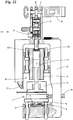
- FIG. 12 finally, the alternative 10 'shows a welding device according to the invention. Functionally identical components have the same reference numerals as in FIGS Figure 2-11 marked.
- the clamping member 25 is not assigned to the ultrasonic welding unit 18 or is arranged on it. Rather, the tensioning element 25 is assigned to the counter element 17.
- the ultrasonic welding unit 18 is not moved, but rather the counter element 17, specifically (upward) in the direction of the ultrasonic sonotrode 19.
- the counter element 17 is in the in Fig. 12
- the manner shown is movably supported on the support part 26 by means of corresponding longitudinal guides 22a, 22b.
Description
Die vorliegende Erfindung betrifft eine Vorrichtung zum Ultraschallschweißen von Materialien, insbesondere Folien, mit einer eine Ultraschallsonotrode aufweisenden Ultraschallschweißeinheit.The present invention relates to a device for ultrasonic welding of materials, in particular foils, with an ultrasonic welding unit having an ultrasonic sonotrode.
Es ist bekannt, Materialien mittels einer Ultraschallschweißeinheit miteinander zu verbinden. Die erforderliche Energie wird dabei durch Ultraschall in die Materialien eingebracht. Die Materialien sind während des Schweißvorgangs zwischen der Ultraschallsonotrode und einem Gegenwerkzeug, wie etwa einem Amboss angeordnet.It is known to connect materials to one another by means of an ultrasonic welding unit. The required energy is introduced into the materials using ultrasound. During the welding process, the materials are arranged between the ultrasonic sonotrode and a counter tool, such as an anvil.
Insbesondere bei dem Verschweißen von Folien besteht ein Problem darin, dass die Folien während des Schweißvorgangs durch einen Plastifizierungsvorgang im Schweißbereich dünner werden bzw. nachgeben. Dies hat unter anderem zur Folge, dass der Schweißdruck, den die Ultraschallsonotrode aufbringt, nicht mehr optimal ist.In particular when welding foils, there is a problem that the foils become thinner or give way during the welding process due to a plasticizing process in the welding area. Among other things, this has the consequence that the welding pressure applied by the ultrasonic sonotrode is no longer optimal.
Die
Die
Die
Die
Ausgehend hiervon ist es Aufgabe der vorliegenden Erfindung, eine Vorrichtung zum Ultraschallschweißen der eingangs genannten Art weiterzuentwickeln.Based on this, it is the object of the present invention to further develop a device for ultrasonic welding of the type mentioned at the beginning.
Diese Aufgabe wird gelöst durch eine Vorrichtung mit den Merkmalen des Anspruchs 1 und eine Vorrichtung mit den Merkmalen des Anspruchs 2.This object is achieved by a device with the features of claim 1 and a device with the features of claim 2.
Die erste Alternative einer erfindungsgemäßen Vorrichtung zum Ultraschallschweißen von Materialien gemäß Anspruch 1 verfügt über einen elektrischen Antriebsmotor, bevorzugt einen Servomotor, zum Verfahren der Ultraschallschweißeinheit unabhängig von der Ultraschallschweißbewegung der Ultraschallsonotrode, sowie über ein pneumatisch betriebenes, in besonderer Weise ausgebildetes und mit den anderen Bauteilen der Vorrichtung zusammenwirkendes Spannorgan. Das Spannorgan weist in einer Schweißstellung der Ultraschallschweißeinheit mindestens zu Beginn des Schweißvorgangs eine geringere Länge auf als in einer Nicht-Schweißstellung. Die Überführung des Spannorgans von dem Zustand größerer Länge in den Zustand kleinerer Länge erfolgt dabei gegen den Widerstand von entgegengerichteten Spannkräften des Spannorgans durch Kompression derselben. In der Schweißstellung vergrößert sich die Länge des Spannorgans bei einem Nachgeben wenigstens eines der zu verschweißenden Materialien aufgrund seiner Spannkräfte, beispielsweise bei einer entsprechenden Reduktion seiner Dicke. Durch die Längenvergrößerung wird eine Bewegung der Ultraschallschweißeinheit in Richtung des nachgebenden Materials bewirkt, sodass auch im Falle des Materialnachgebens ein ausreichender Kontakt zwischen Sonotrode und Material(-ien) besteht bzw. ein ausreichender Schweißdruck erzeugt wird.The first alternative of a device according to the invention for ultrasonic welding of materials according to claim 1 has an electric drive motor, preferably a servomotor, for moving the ultrasonic welding unit independently of the ultrasonic welding movement of the ultrasonic sonotrode, as well as a pneumatically operated, specially designed and with the other components of the Device cooperating tensioning element. In a welding position of the ultrasonic welding unit, the clamping element has a shorter length at least at the beginning of the welding process than in a non-welding position. The transfer of the tensioning member from the state of greater length to the condition of shorter length takes place against the resistance of opposing tensioning forces of the tensioning member by compression of the same. In the welding position, the length of the clamping member increases when at least one of the materials to be welded yields due to its clamping forces, for example when its thickness is correspondingly reduced. The increase in length causes the ultrasonic welding unit to move in the direction of the yielding material causes sufficient contact between the sonotrode and the material (s) or a sufficient welding pressure to be generated even in the event of material yielding.
Bevorzugt ist dabei das Spannorgan Teil der mit dem Antriebsmotor verfahrbaren Ultraschallschweißeinheit.The clamping element is preferably part of the ultrasonic welding unit that can be moved with the drive motor.
Die zweite Alternative der erfindungsgemäßen Vorrichtung gemäß Anspruch 2 unterscheidet sich von der ersten Alternative insbesondere insofern, als dass die Längenvergrößerung des Spannorgans in der Schweißstellung bei Nachgeben des mindestens einen Materials nicht zu einer Bewegung der Ultraschallschweißeinheit in Richtung des nachgebenden Materials führt, sondern zu einer entsprechenden Bewegung des Gegenorgans, zwischen dem und der Ultraschallsonotrode die zu verschweißenden Materialien während des Schweißvorgangs angeordnet sind, sodass auch hier im Falle des Materialnachgebens ein guter Kontakt zwischen Sonotrode und Material(-ien) besteht bzw. ein ausreichender Schweißdruck erzeugt wird.The second alternative of the device according to the invention according to claim 2 differs from the first alternative in particular in that the increase in length of the clamping member in the welding position when the at least one material yields does not lead to a movement of the ultrasonic welding unit in the direction of the yielding material, but to a corresponding movement Movement of the counter-organ between which and the ultrasonic sonotrode the materials to be welded are arranged during the welding process, so that here too, in the event of material yielding, there is good contact between the sonotrode and the material (s) or sufficient welding pressure is generated.
Beide Alternativen weisen entsprechend gegenüber dem Stand der Technik unter anderem den Vorteil auf, dass für eine Aufrechterhaltung ausreichenden Schweißdrucks bei Nachgeben der zu verschweißenden Materialien keine aufwendige Bewegungssteuerung eines Linearmotors notwendig ist, der für eine entsprechende Nachführung des Gegenorgans sorgen müsste.Compared to the state of the art, both alternatives have the advantage that, in order to maintain sufficient welding pressure when the materials to be welded give way, no complex motion control of a linear motor is necessary, which would have to ensure a corresponding tracking of the counter element.
Bevorzugt ist vorgesehen, dass das Spannorgan gerade bei Verfahren der Ultraschallschweißeinheit von der Nicht-Schweißstellung in die Schweißstellung durch die Gegenkraft des Gegenorgans, zwischen dem und der Ultraschallsonotrode die zu verschweißenden Materialien während des Schweißvorgangs angeordnet sind, von dem oben erwähnten Zustand, in dem es die größere Länge aufweist, in den Zustand überführt bzw. komprimiert wird, in dem es die kleinere Länge aufweist.It is preferably provided that the clamping element, especially when the ultrasonic welding unit is moved from the non-welding position to the welding position, by the opposing force of the counter-element between which and the ultrasonic sonotrode the materials to be welded are arranged during the welding process, from the above-mentioned state in which it has the greater length, is converted or compressed into the state in which it has the smaller length.
Was das Spannorgan betrifft, so weist es vorzugsweise einen ersten Bereich oder ein erstes Bauteil auf sowie einen zweiten Bereich oder ein zweites Bauteil, die zur Längenänderung insbesondere in Längsrichtung der Vorrichtung relativ zueinander bewegbar sind.As far as the clamping element is concerned, it preferably has a first area or a first component and a second area or a second component, which can be moved relative to one another in order to change length, in particular in the longitudinal direction of the device.
In der ersten erfindungsgemäßen Alternative gemäß Anspruch 1 kann dabei das erste Bauteil oder der erste Bereich mittelbar oder unmittelbar (fest) mit dem Antriebsmotor verbunden sein, und das zweite Bauteil oder der zweite Bereich mittelbar oder unmittelbar (fest) mit der Ultraschallsonotrode.In the first alternative according to the invention according to claim 1, the first component or the first area can be connected directly or indirectly (fixed) to the drive motor, and the second component or the second area can be connected directly or indirectly (fixed) to the ultrasonic sonotrode.
Für beide Alternativen gilt allerdings vorzugsweise, dass der erste Bereich oder das erste Bauteil in dem Zustand des Spannorgans, in dem es eine größere Länge aufweist, einen größeren Abstand von dem zweiten Bereich oder dem zweiten Bauteil aufweist als in dem Zustand, in dem es eine kleinere Länge aufweist.For both alternatives, however, it preferably applies that the first area or the first component in the state of the clamping member in which it has a greater length is at a greater distance from the second area or the second component than in the state in which it has a has a smaller length.
Vorzugsweise weist das Spannorgan als zweites Bauteil ein (insbesondere zylindrisches) Gehäuse auf und als erstes Bauteil ein innerhalb des Gehäuses relativ zu diesem durch Druckluft bewegbares Hubelement.The tensioning element preferably has a (in particular cylindrical) housing as the second component and, as the first component, a lifting element which can be moved within the housing relative to the latter by compressed air.
Als Spannorgan kann beispielsweise ein in der Technik bekanntes Pneumatikspannmodul verwendet werden, bei dem eine innerhalb eines Gehäuses mittels Druckluft bewegbare Membran mit einem von der Membran bewegbaren Hubelement bzw. Stempel zusammenwirkt. In gleicher Weise können auch Pneumatikzylinder mit einem bewegbaren, in einem Gehäuse als Kolben ausgebildeten Hubelement eingesetzt werden.For example, a pneumatic clamping module known in the art can be used as the clamping element, in which a membrane movable within a housing by means of compressed air interacts with a lifting element or plunger movable from the membrane. In the same way, pneumatic cylinders with a movable lifting element embodied as a piston in a housing can also be used.
Unabhängig von der konkreten Ausbildung desselben kann das Spannorgan bei der zweiten Alternative der erfindungsgemäßen Vorrichtung derart betrieben werden und ist vorzugsweise auch bei der ersten Alternative derart ausgebildet oder kann derart betrieben werden, dass die Spannkraft pro Wegstrecke, die das Spannorgan in der Schweißstellung einer Verringerung seiner Länge entgegensetzt oder - abstrakt betrachtet - entgegensetzen würde, vor der Vergrößerung seiner Länge bei Nachgeben des Materials dieselbe oder im Wesentlichen dieselbe ist wie nach der Vergrößerung seiner Länge.Regardless of the specific design of the same, the clamping element can be operated in the second alternative of the device according to the invention and is preferably also designed or operated in such a way in the first alternative that the clamping force per distance that the clamping element in the welding position reduces its Length opposed or - viewed abstractly - would oppose before the increase in its length is the same or substantially the same when the material yields as after the increase in its length.
Zweckmäßiger Weise ist das pneumatisch betriebene Spannorgan an eine Druckluftquelle angeschlossen. Dabei kann die Druckluftquelle vorteilhafterweise derart gesteuert oder geregelt sein, dass in der Schweißstellung der Ultraschallschweißeinheit der auf das Hubelement wirkende Luftdruck vor dem Nachgeben des Materials und nach dem Nachgeben des Materials gleich oder im Wesentlichen gleich ist.The pneumatically operated clamping element is expediently connected to a compressed air source. The compressed air source can advantageously be controlled or regulated in such a way that, in the welding position of the ultrasonic welding unit, the air pressure acting on the lifting element is the same or essentially the same before the material yields and after the material yields.
In weiterer Ausbildung der Erfindung weist die Schweißvorrichtung eine von dem Antriebsmotor angetriebene, mit der Ultraschallschweißeinheit verbundene Kurbelwelle auf, die Drehbewegungen in Translationsbewegungen zum Verfahren der Ultraschallschweißeinheit in die Schweißstellung bzw. aus der Schweißstellung in die Nicht-Schweißstellung übersetzt.In a further embodiment of the invention, the welding device has a crankshaft driven by the drive motor and connected to the ultrasonic welding unit, which translates rotary movements into translational movements for moving the ultrasonic welding unit into the welding position or from the welding position into the non-welding position.
Die Ultraschallschweißeinheit ist bevorzugt während ihrer Verfahrbewegung in Längsrichtung der Vorrichtung geführt, insbesondere durch ein oder mehrere (Längs-)Führungen.The ultrasonic welding unit is preferably guided during its movement in the longitudinal direction of the device, in particular by one or more (longitudinal) guides.
Bevorzugt ist das Spannorgan zusammen mit der Ultraschallsonotrode und einem Ultraschallkonverter an einem Schlitten der Ultraschallschweißeinheit angeordnet, der beim Verfahren der Ultraschallschweißeinheit gemeinsam mit den vorgenannten Bauteilen von der Nicht-Schweißstellung in die Schweißstellung bewegt wird.The clamping element is preferably arranged together with the ultrasonic sonotrode and an ultrasonic converter on a slide of the ultrasonic welding unit which is moved from the non-welding position to the welding position together with the aforementioned components when the ultrasonic welding unit is moved.
Der von dem Gehäuse entfernte Endbereich des Hubelements kann zweckmäßigerweise mittelbar oder unmittelbar mit einem mit der Kurbellwelle zugeordneten Pleuel verbunden sein.The end region of the lifting element remote from the housing can expediently be connected directly or indirectly to a connecting rod associated with the crankshaft.
Weitere Merkmale der vorliegenden Erfindung ergeben sich aus den beigefügten Patentansprüchen, der nachfolgenden Beschreibung bevorzugter Ausführungsbeispiele sowie den beigefügten Zeichnungen. Darin zeigt:
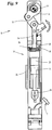
- Fig. 1
- als Beispiel für eine konkrete Verwendung einer erfindungsgemäßen Schweißvorrichtung zum Ultraschallschweißen das Aufbringen von Schweißnähten auf eine Folienbahn im Rahmen der Herstellung von Beuteln für Tabak,
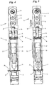
- Fig. 2
- eine Vorderansicht einer ersten Alternative einer erfindungsgemäßen Schweißvorrichtung,
- Fig. 3
- die Vorderansicht aus
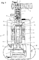
Fig. 2 , teilweise geschnitten, - Fig. 4
- eine Schnittdarstellung entlang der Schnittstelle IV-IV aus
Fig. 3 in einer Nicht-Schweißstellung der Schweißvorrichtung, - Fig. 5
- eine Darstellung analog
Fig. 4 in einer Schweißstellung der Schweißvorrichtung, - Fig. 6
- eine Darstellung der Schweißvorrichtung in einer Nicht-Schweißstellung analog
Fig. 4 , allerdings teilweise gebrochen, - Fig. 7
- eine Darstellung analog
Fig. 6 , allerdings in einer Schweißstellung der Schweißvorrichtung, und zwar zu Beginn des Schweißvorgangs, - Fig. 8
- eine Darstellung der Schweißvorrichtung analog zu
Fig. 6 , und zwar zu einem späteren Zeitpunkt des Schweißvorgangs, - Fig. 9
- eine Darstellung der Schweißvorrichtung analog zu
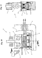
Fig. 4 , allerdings in einer Reinigungsstellung der Vorrichtung, - Fig. 10
- die Einzelheit X aus
Fig. 3 in vergrößerter Darstellung, - Fig. 11
- einen Schnitt entlang der Schnittlinie XI-XI aus
Fig. 10 , - Fig. 12
- eine teilweise geschnittene Vorderansicht einer zweiten Alternative einer erfindungsgemäßen Ultraschallschweißvorrichtung.
- Fig. 1
- as an example of a specific use of a welding device according to the invention for ultrasonic welding, the application of weld seams to a film web in the context of the production of bags for tobacco,
- Fig. 2
- a front view of a first alternative of a welding device according to the invention,
- Fig. 3
- the front view
Fig. 2 , partially cut, - Fig. 4
- a sectional view along the interface IV-IV
Fig. 3 in a non-welding position of the welding device, - Fig. 5
- a representation analogous
Fig. 4 in a welding position of the welding device, - Fig. 6
- a representation of the welding device in a non-welding position analogous
Fig. 4 , but partly broken, - Fig. 7
- a representation analogous
Fig. 6 , but in a welding position of the welding device, namely at the beginning of the welding process, - Fig. 8
- a representation of the welding device analogous to
Fig. 6 at a later point in the welding process, - Fig. 9
- a representation of the welding device analogous to
Fig. 4 , but in a cleaning position of the device, - Fig. 10
- the detail X from
Fig. 3 in an enlarged view, - Fig. 11
- a section along the section line XI-XI
Fig. 10 , - Fig. 12
- a partially sectioned front view of a second alternative of an ultrasonic welding device according to the invention.
Mit einer erfindungsgemäßen Vorrichtung zum Ultraschallschweißen lassen sich diverse Materialien miteinander verschweißen. So beispielsweise Abschnitte 11 und 12 einer Folienbahn 13 zur Herstellung von Tabakbeuteln 14, vgl.
Wichtig sind vielmehr der Aufbau und die Funktionsweise der in den
Die erste Alternative 10 der erfindungsgemäßen Schweißvorrichtung, vgl.
An ihrem dem Gegenorgan 17 zugekehrten Ende weist die Ultraschallschweißeinheit 18 eine in ihrer Funktionsweise und ihrem Aufbau an sich bekannte Ultraschallsonotrode 19 auf, die bei Bewegung der Ultraschallschweißeinheit 18 mitbewegt wird.At its end facing the opposing
Als zu verschweißende Materialien 20, 21 sind in
Die Ultraschallschweißeinheit 18 verfügt des Weiteren über einen an Längsführungen 22a, 22b gelagerten Schlitten 23, an dem unter anderem die Ultraschallsonotrode 19 und ein die Ultraschallsonotrode 19 speisender Ultraschallkonverter 24 befestigt bzw. gelagert sind. Weiter ist daran ein Spannorgan 25 angeordnet, auf das nachfolgend noch näher eingegangen wird.The
Die Ultraschallschweißeinheit 18 ist mittels des Schlittens 23 relativ zu einem ortsfesten Tragteil 26 verfahrbar, vorliegend einem Rahmen oder Gestell, an dem die Längsführungen 22a, 22b befestigt bzw. gelagert sind.The
An dem Tragteil 26 ist weiter eine Kühlluftdüse 27 befestigt, die zur Verhinderung übermäßiger Erwärmung der Ultraschallsonotrode 19 im Betrieb der Vorrichtung 10 der Sono-trode 19 kalte Luft zuführt.A cooling
Wie insbesondere in
Ebenfalls in
Das Verfahren der Ultraschallschweißeinheit 18 relativ zu dem Tragteil 26 bzw. zu dem Gegenorgan 17 und den zu verschweißenden Materialien 20, 21 erfolgt mittels eines elektrischen Antriebsmotors 30, vorliegend eines Servomotors.The movement of the
Dieser treibt gezielt eine Kurbelwelle 31 an, auf der ein Pleuel 32 gelagert ist. Der Pleuel 32 ist mit der Ultraschallschweißeinheit 18 wirkverbunden, sodass eine Bewegung der Kurbelwelle 31 in eine erste Richtung, vgl.
Eine entgegengesetzte Drehbewegung der Kurbelwelle 31 bewirkt entsprechend eine (nach oben gerichtete) Bewegung der Ultraschallschweißeinheit 18 in die entgegengesetzte Richtung, das heißt von dem Gegenorgan 17 weg.An opposite rotational movement of the
Die Ultraschallschweißeinheit 18 kann unabhängig von den Vibrationen bzw. Ultraschallbewegungen der Ultraschallsonotrode 19 von einer Nicht-Schweißstellung, vgl. beispielsweise
Im vorliegenden Ausführungsbeispiel ist der Pleuel 32 mit der Ultraschallschweißeinheit 18 verbunden über ein Zwischenstück 18, das einerseits gelenkig mit dem Pleuel 32 verbunden ist, andererseits gelenkig mit dem Spannorgan 25.In the present exemplary embodiment, the connecting
Das Spannorgan 25 umfasst vorliegend ein (stangenartiges) Hubelement 34 bzw. einen Stempel, das innerhalb eines vorliegend (hohl-)zylindrischen Gehäuses 35 verschiebbar bzw. relativ zu diesem bewegbar gelagert ist.In the present case, the
Das Spannorgan 25 ist letztlich Teil der Ultraschallschweißeinheit 18.The clamping
Das Gehäuse 35 desselben ist dabei fest an dem Schlitten 23 angeordnet bzw. an diesem befestigt. Das Hubelement 34, das innerhalb des Gehäuses 35 bewegbar ist, ist an seinem von dem Gehäuse 35 abgekehrten Ende - wie oben bereits angedeutet - mittelbar mit dem Antriebsmotor 30 verbunden (über das Zwischenstück 33, den Pleuel 32 und die Kurbelwelle 31). An seinem anderen Ende stützt es sich auf einer innerhalb des Gehäuses 35 angeordneten Membran 36 ab.The
Das Spannorgan 25 hat die Aufgabe, in der Schweißstellung der Ultraschallschweißeinheit 18 bei einem Nachgeben eines der zu verschweißenden Materialien 20, 21 oder beider Materialen, insbesondere wenn diese durch den Energieeintrag während des Schweißvorgangs in Folge von Plastizierungsvorgängen dünner werden, dieses Nachgeben auszugleichen bzw. diesem entgegenzuwirken.In the welding position of the
Zu diesem Zweck verlängert sich das Spannorgan 25 in der Schweißstellung bei einem Nachgeben der Materialien 20, 21 in Längsrichtung, was im Ergebnis zu einem Verfahren der Ultraschallschweißeinheit 18 und mithin auch der Ultraschallsonotrode 19 in Richtung der nachgebenden Materialien 20, 21 führt.For this purpose, the clamping
Die Zusammenhänge werden im Detail nachfolgend anhand der
Das Spannmodul 25 ist vorliegend als Pneumatikspannmodul ausgebildet.The
In der in
In
In
Während der in den
Denkbar ist auch, dass der Luftdruck gar nicht geregelt oder gesteuert wird, sondern sich abhängig von dem jeweiligen Bewegungszustand eigenständig einstellt.It is also conceivable that the air pressure is not regulated or controlled at all, but adjusts itself independently depending on the respective state of movement.
Gemäß einer weiteren Besonderheit der Vorrichtung 10 ist im Übrigen noch vorgesehen, diese außerhalb des Standardbetriebs in eine Reinigungsstellung überführen zu können, vgl.
Zu diesem Zweck ist zwischen dem Antriebsmotor 30 und der Ultraschallschweißeinheit 18 ein Knickgelenk angeordnet ist, das aus einer nicht abgewinkelten Betriebsstellung, in der das Knickgelenk Bewegungsenergie des Antriebsmotors 30 zum Verfahren der Ultraschallschweißeinheit 18 auf diese übertragen kann, in eine abgewinkelte Reinigungsstellung überführbar ist, in der die Ultraschallschweißeinheit 18 aufgrund der abgewinkelten Stellung des Knickgelenks einen größeren Abstand von dem Gegenorgan 17 aufweist als in der Betriebsstellung.For this purpose, an articulated joint is arranged between the
Ein erster Arm des Knickgelenks wird dabei durch das Zwischenstück 33 gebildet, ein zweiter Arm durch den an dem Zwischenstück 33 drehbar angelenkten Pleuel 32.A first arm of the articulated joint is formed by the
Das Knickgelenk kann aus der in den
Hierzu kann von einem Bediener ein Arretierstift 38 gelöst werden, der im Betrieb der Vorrichtung 10 ein Verschwenken des Knickhebels und insbesondere des Zwischenstücks 33 relativ zu dem Pleuel 32 bzw. dem Hubelement 34 verhindert. Im Anschluss können die beiden Arme des Knickhebels händisch in die in
Hierdurch werden die Ultraschallschweißeinheit 18 bzw. der Schlitten 23 von dem Gegenorgan 17 weg (nach oben) in die Reinigungsstellung bewegt, in der das Gegenorgan 17 zugänglich ist und der es möglich ist, das Gegenorgan 17 zu entfernen.As a result, the
Das Gegenorgan 17 ist zu diesem Zweck mehrteilig ausgebildet. So könnte der obere, in
Im Unterschied zu der Vorrichtung 10 ist bei der Vorrichtung 10' das Spannorgan 25 allerdings nicht der Ultraschallschweißeinheit 18 zugeordnet bzw. an dieser angeordnet. Das Spannorgan 25 ist vielmehr dem Gegenorgan 17 zugeordnet. Entsprechend wird bei einem Nachgeben der Materialien 20, 21 durch eine entsprechende Verlängerung des Spannorgans 25 nicht die Ultraschallschweißeinheit 18 bewegt, sondern das Gegenorgan 17, und zwar (nach oben) in Richtung der Ultraschallsonotrode 19. Zu diesem Zweck ist das Gegenorgan 17 in der in
Claims (15)
- Device for the ultrasonic welding of materials (20, 21), in particular films, having an ultrasonic welding unit (18) which has an ultrasonic somatrode (19), having an electric drive motor (30) for moving the ultrasonic welding unit (18) independently of the ultrasonic welding movement of the ultrasonic somatrode (19), and having a clamping member (25) which, in a welding position of the ultrasonic welding unit (18), is reduced in its length with respect to a non-welding position against the resistance of oppositely directed clamping forces and which is increased in its length in the welding position during a yielding of at least one of the materials to be welded during the welding operation on account of its clamping forces and, as a result of the increase in length, causes a movement of the ultrasonic welding unit (18) in the direction of the yielding material, characterized in that the clamping member (25) is pneumatically operated.
- Device for the ultrasonic welding of materials (20, 21), in particular films, having an ultrasonic welding unit (18) which has an ultrasonic somatrode (19), having an electric drive motor (30) for moving the ultrasonic welding unit (18) independently of the ultrasonic welding movement of the ultrasonic somatrode (19) in the direction of a counter-member (17) between which and the ultrasonic somatrode (19) the materials (20, 21) to be welded are arranged during the welding operation, and having a pneumatically operated clamping member (25) which, in a welding position of the ultrasonic welding unit (18), is reduced in its length with respect to a non-welding position against the resistance of oppositely directed clamping forces and which is increased in its length in the welding position during a yielding of at least one of the materials (20, 21) to be welded during the welding operation on account of its clamping forces and, as a result of the increase in length, causes a movement of the counter-member (17) in the direction of the ultrasonic somatrode (19), wherein the clamping member (25) can be operated in such a way that the clamping force per distance which the clamping member (25) in the welding position counters or would counter to a reduction in its length is the same before the increase in its length during yielding of the material (20, 21) or substantially the same as after the increase in its length.
- Device according to Claim 1 or 2, characterized in that, during movement of the ultrasonic welding unit (18) from the non-welding position into the welding position, the clamping member (25) is converted or compressed from the state in which it has a larger length into the state in which it has a smaller length by the counter-force of a counter-member (17) between which and the ultrasonic somatrode the materials (20, 21) to be welded are arranged during the welding operation.
- Device according to Claim 1 or 3, characterized in that the clamping member (25) is part of the ultrasonic welding unit (18) which can be moved by the drive motor (30).
- Device according to one or more of the preceding claims, characterized in that the clamping member (25) has a first region or first component (34) and a second region or a second component (35) which, for a change in length, in particular in the longitudinal direction of the device (10, 10'), are movable relative to one another.
- Device according to Claim 5, characterized in that the first component (34) or the first region is connected indirectly or directly (fixedly) to the drive motor (30), and the second component (35) or the second region is connected indirectly or directly (fixedly) to the ultrasonic somatrode (19).
- Device according to Claims 5 or 6, characterized in that the first region or the first component (34) has a larger (longitudinal) distance from the second region or the second component (35) in the state of the clamping member (25) in which it has a larger length than in the state in which it has a smaller length.
- Device according to one or more of the preceding claims, characterized in that the clamping member (25) has, as second component, a housing (35) and, as first component, a reciprocating element (34) which is movable within the housing (35) relative to the latter by means of compressed air.
- Device according to Claim 8, characterized in that the clamping member (25) is connected to a compressed-air source, and in that the compressed-air source is controlled or regulated in such a way that, in the welding position of the ultrasonic welding unit (18), the air pressure acting on the reciprocating element (34) is identical or substantially identical before the yielding of the material (20, 21) and after the yielding of the material (20, 21) .
- Device according to one or more of the preceding claims, characterized in that the device (10, 10') has a crankshaft (31) which is driven by the drive motor (30), is connected to the ultrasonic welding unit (18) and converts rotational movements into translational movements in order to move the ultrasonic welding unit (18) into the welding position or out of the welding position into the non-welding position.
- Device according to one or more of the preceding claims, characterized in that the ultrasonic welding unit (18) is guided during its travel movement, in particular by one of more guides (22a, 22b).
- Device according to one or more of the preceding claims, characterized in that the clamping member (25), together with the ultrasonic somatrode (19) and an ultrasonic converter (24), is arranged on a carriage (23) of the ultrasonic welding unit (18) that, during the movement of the ultrasonic welding unit (18), is moved jointly with the aforementioned components from the non-welding position into the welding position.
- Device according to Claim 10, characterized in that the end region of the reciprocating element (34) that is remote from the housing (35) is connected indirectly or directly to a connecting rod (32) assigned to the crankshaft (31).
- Device according to one or more of the preceding claims, characterized in that an articulated joint is arranged between the drive motor (30) and ultrasonic welding unit (18) and can be transferred from a non-angled operating position, in which the articulated joint can transmit movement energy of the drive motor (30) to the ultrasonic welding unit (18) in order to move the latter, into an angled cleaning position in which the ultrasonic welding unit (18) has a greater distance from the counter-member (17) than in the operating position on account of the angled position of the articulated joint.
- Device according to Claim 10 and 14, characterized in that a first arm of the articulated joint is formed by the connecting rod (32), and a second arm is formed by an intermediate piece (34) which is rotatably articulated on the reciprocating element (34) .
Priority Applications (1)
| Application Number | Priority Date | Filing Date | Title |
|---|---|---|---|
| PL17000493T PL3231585T3 (en) | 2016-04-11 | 2017-03-24 | Device for ultrasonic welding |
Applications Claiming Priority (1)
| Application Number | Priority Date | Filing Date | Title |
|---|---|---|---|
| DE102016004180.3A DE102016004180A1 (en) | 2016-04-11 | 2016-04-11 | Apparatus for ultrasonic welding |
Publications (2)
| Publication Number | Publication Date |
|---|---|
| EP3231585A1 EP3231585A1 (en) | 2017-10-18 |
| EP3231585B1 true EP3231585B1 (en) | 2020-10-14 |
Family
ID=58428034
Family Applications (1)
| Application Number | Title | Priority Date | Filing Date |
|---|---|---|---|
| EP17000493.1A Active EP3231585B1 (en) | 2016-04-11 | 2017-03-24 | Device for ultrasonic welding |
Country Status (3)
| Country | Link |
|---|---|
| EP (1) | EP3231585B1 (en) |
| DE (1) | DE102016004180A1 (en) |
| PL (1) | PL3231585T3 (en) |
Families Citing this family (3)
| Publication number | Priority date | Publication date | Assignee | Title |
|---|---|---|---|---|
| CN108555429B (en) * | 2018-05-16 | 2023-06-20 | 华侨大学 | Large-range continuous ultrasonic welding device for metal foil |
| CN112692423B (en) * | 2020-12-16 | 2023-05-30 | 上海骄成超声波技术股份有限公司 | Ultrasonic welder |
| CN114750417A (en) * | 2022-03-25 | 2022-07-15 | 必能信超声(上海)有限公司 | Ultrasonic plastic welding rack |
Citations (10)
| Publication number | Priority date | Publication date | Assignee | Title |
|---|---|---|---|---|
| US5575884A (en) | 1994-09-28 | 1996-11-19 | Tetra Laval Holdings & Finance S.A. | Ultrasonic piston converter |
| WO1998038091A1 (en) | 1997-02-26 | 1998-09-03 | Baxter International Inc. | Method and apparatus for manufacturing intravenous solution bags |
| JP2000141490A (en) | 1998-11-04 | 2000-05-23 | Nippon Jido Seiki Kk | Film welding apparatus |
| US6491785B1 (en) | 1999-06-16 | 2002-12-10 | Ultex Corporation | Ultrasonic vibration bonding machine |
| US20040106506A1 (en) | 2001-03-28 | 2004-06-03 | Akihide Ninomiya | Sealing apparatus and manufacturing process of soft article having sealed portion |
| US20070251362A1 (en) | 2006-04-26 | 2007-11-01 | Herrmann Ultraschalltechnik Gmbh & Co.Kg | Device for processing workpieces using ultrasound and method for operating that device |
| US20070296104A1 (en) | 2005-10-20 | 2007-12-27 | Shannon Thomas G | High speed, pressure bonded, thin sheet laminate |
| US20080105385A1 (en) | 2006-05-11 | 2008-05-08 | Hans-Peter Wild | Anvil for ultrasonic welding and device for ultrasonic welding |
| US7819158B2 (en) | 2006-05-08 | 2010-10-26 | Dukane Corporation | Ultrasonic press using servo motor with integrated linear actuator |
| DE102011006932A1 (en) | 2011-04-07 | 2012-10-11 | Widmann Maschinen E.K. | Apparatus, useful for welding, cutting and/or punching workpieces by ultrasound, comprises ultrasonic sonotrode, and counter tool as well as drive for displacing sonotrode or counter tool independent of ultrasonic welding movement |
Family Cites Families (5)
| Publication number | Priority date | Publication date | Assignee | Title |
|---|---|---|---|---|
| EP0790888B1 (en) * | 1994-11-07 | 1999-06-09 | Herrmann Ultraschalltechnik GmbH & Co. KG | Continuous ultrasound machining process and device for webs of material |
| BRPI0518540B1 (en) * | 2005-01-03 | 2017-02-14 | 3M Innovative Properties Co | clearance adjustment method for an ultrasonic welding system |
| DE102010060401A1 (en) * | 2010-11-08 | 2012-05-10 | Sartorius Weighing Technology Gmbh | Welding device, use thereof as a control valve and metering device |
| JP5779761B2 (en) * | 2011-09-15 | 2015-09-16 | 精電舎電子工業株式会社 | Ultrasonic welding equipment, ultrasonic welding equipment, wiring equipment |
| US9550323B2 (en) * | 2013-09-06 | 2017-01-24 | GM Global Technology Operations LLC | Systems and methods for adaptive process control using a target kinematics profile in welding together multiple polymeric workpieces |
-
2016
- 2016-04-11 DE DE102016004180.3A patent/DE102016004180A1/en not_active Withdrawn
-
2017
- 2017-03-24 PL PL17000493T patent/PL3231585T3/en unknown
- 2017-03-24 EP EP17000493.1A patent/EP3231585B1/en active Active
Patent Citations (10)
| Publication number | Priority date | Publication date | Assignee | Title |
|---|---|---|---|---|
| US5575884A (en) | 1994-09-28 | 1996-11-19 | Tetra Laval Holdings & Finance S.A. | Ultrasonic piston converter |
| WO1998038091A1 (en) | 1997-02-26 | 1998-09-03 | Baxter International Inc. | Method and apparatus for manufacturing intravenous solution bags |
| JP2000141490A (en) | 1998-11-04 | 2000-05-23 | Nippon Jido Seiki Kk | Film welding apparatus |
| US6491785B1 (en) | 1999-06-16 | 2002-12-10 | Ultex Corporation | Ultrasonic vibration bonding machine |
| US20040106506A1 (en) | 2001-03-28 | 2004-06-03 | Akihide Ninomiya | Sealing apparatus and manufacturing process of soft article having sealed portion |
| US20070296104A1 (en) | 2005-10-20 | 2007-12-27 | Shannon Thomas G | High speed, pressure bonded, thin sheet laminate |
| US20070251362A1 (en) | 2006-04-26 | 2007-11-01 | Herrmann Ultraschalltechnik Gmbh & Co.Kg | Device for processing workpieces using ultrasound and method for operating that device |
| US7819158B2 (en) | 2006-05-08 | 2010-10-26 | Dukane Corporation | Ultrasonic press using servo motor with integrated linear actuator |
| US20080105385A1 (en) | 2006-05-11 | 2008-05-08 | Hans-Peter Wild | Anvil for ultrasonic welding and device for ultrasonic welding |
| DE102011006932A1 (en) | 2011-04-07 | 2012-10-11 | Widmann Maschinen E.K. | Apparatus, useful for welding, cutting and/or punching workpieces by ultrasound, comprises ultrasonic sonotrode, and counter tool as well as drive for displacing sonotrode or counter tool independent of ultrasonic welding movement |
Also Published As
| Publication number | Publication date |
|---|---|
| PL3231585T3 (en) | 2021-05-04 |
| DE102016004180A1 (en) | 2017-10-12 |
| EP3231585A1 (en) | 2017-10-18 |
Similar Documents
| Publication | Publication Date | Title |
|---|---|---|
| EP1915270B1 (en) | Method for connecting the ends of profiled sealing elements, and device for carrying out said method | |
| EP0456121B1 (en) | Method of bending plate-like workpieces and bending machine for carrying out this method | |
| EP2177287B1 (en) | Support split assembly for gliding side supports of rod and tube-shape workpieces on bending machines | |
| DE102007051894B4 (en) | Release mechanism and provided with this straightening device | |
| EP2008736B1 (en) | Machine tool and method for discharging a workpiece part | |
| DE102012102527B4 (en) | Press drive with several working areas | |
| EP3231585B1 (en) | Device for ultrasonic welding | |
| EP2547470B1 (en) | Device for cutting nail blanks from an intermittently fed wire | |
| EP2842718A2 (en) | Extrusion tool for generating tubular preforms | |
| EP2915651A1 (en) | Method for the production of blow moulded plastic hollow bodies and multiple extrusion head for carrying out the method | |
| WO2019001982A1 (en) | Method for producing a bent part and bending machine for performing the method | |
| EP3222407B1 (en) | Automatic welding machine | |
| EP3208071B1 (en) | Automatic welding machine | |
| EP2661353A1 (en) | Device and method for producing tubes for packaging tubes | |
| EP3160726B1 (en) | Improved c-frame press | |
| DE102018000344B3 (en) | Bending machine, bending unit, electronic control device and method for bending a workpiece from flat material | |
| EP2095930A2 (en) | Method and device for connecting objects | |
| EP2447043A2 (en) | Method for the energy-efficient sealing of tubular bags | |
| DE102015006421B4 (en) | Process for joining components | |
| WO2004007107A1 (en) | Extruding press and extruding method | |
| DE102011002313A9 (en) | Extrusion tool for the production of flat preforms from a plastic melt | |
| WO2014191284A1 (en) | Press and method for operating the press | |
| EP1892188B1 (en) | Device for welding the lateral sides of a bag blank | |
| EP3552729B1 (en) | Punch riveting device | |
| DE102012111117A1 (en) | Extrusion tool for producing tubular preform from plastic melt, has nozzle ring comprising deformable mouth region, and resilient deformable case attached with connection head and projected to bottom of connection head and mouth region |
Legal Events
| Date | Code | Title | Description |
|---|---|---|---|
| PUAI | Public reference made under article 153(3) epc to a published international application that has entered the european phase |
Free format text: ORIGINAL CODE: 0009012 |
|
| STAA | Information on the status of an ep patent application or granted ep patent |
Free format text: STATUS: THE APPLICATION HAS BEEN PUBLISHED |
|
| AK | Designated contracting states |
Kind code of ref document: A1 Designated state(s): AL AT BE BG CH CY CZ DE DK EE ES FI FR GB GR HR HU IE IS IT LI LT LU LV MC MK MT NL NO PL PT RO RS SE SI SK SM TR |
|
| AX | Request for extension of the european patent |
Extension state: BA ME |
|
| STAA | Information on the status of an ep patent application or granted ep patent |
Free format text: STATUS: REQUEST FOR EXAMINATION WAS MADE |
|
| 17P | Request for examination filed |
Effective date: 20180417 |
|
| RBV | Designated contracting states (corrected) |
Designated state(s): AL AT BE BG CH CY CZ DE DK EE ES FI FR GB GR HR HU IE IS IT LI LT LU LV MC MK MT NL NO PL PT RO RS SE SI SK SM TR |
|
| STAA | Information on the status of an ep patent application or granted ep patent |
Free format text: STATUS: EXAMINATION IS IN PROGRESS |
|
| 17Q | First examination report despatched |
Effective date: 20190704 |
|
| GRAP | Despatch of communication of intention to grant a patent |
Free format text: ORIGINAL CODE: EPIDOSNIGR1 |
|
| STAA | Information on the status of an ep patent application or granted ep patent |
Free format text: STATUS: GRANT OF PATENT IS INTENDED |
|
| RIC1 | Information provided on ipc code assigned before grant |
Ipc: B29L 7/00 20060101ALN20200402BHEP Ipc: B29C 65/08 20060101AFI20200402BHEP |
|
| INTG | Intention to grant announced |
Effective date: 20200506 |
|
| GRAS | Grant fee paid |
Free format text: ORIGINAL CODE: EPIDOSNIGR3 |
|
| RIN1 | Information on inventor provided before grant (corrected) |
Inventor name: SCHNAKENBERG, JAN Inventor name: LEIFHEIT, AXEL Inventor name: STORCKS, ANDREAS |
|
| GRAA | (expected) grant |
Free format text: ORIGINAL CODE: 0009210 |
|
| STAA | Information on the status of an ep patent application or granted ep patent |
Free format text: STATUS: THE PATENT HAS BEEN GRANTED |
|
| AK | Designated contracting states |
Kind code of ref document: B1 Designated state(s): AL AT BE BG CH CY CZ DE DK EE ES FI FR GB GR HR HU IE IS IT LI LT LU LV MC MK MT NL NO PL PT RO RS SE SI SK SM TR |
|
| REG | Reference to a national code |
Ref country code: GB Ref legal event code: FG4D Free format text: NOT ENGLISH |
|
| REG | Reference to a national code |
Ref country code: CH Ref legal event code: EP Ref country code: AT Ref legal event code: REF Ref document number: 1323152 Country of ref document: AT Kind code of ref document: T Effective date: 20201015 |
|
| REG | Reference to a national code |
Ref country code: DE Ref legal event code: R096 Ref document number: 502017007696 Country of ref document: DE |
|
| REG | Reference to a national code |
Ref country code: IE Ref legal event code: FG4D Free format text: LANGUAGE OF EP DOCUMENT: GERMAN |
|
| REG | Reference to a national code |
Ref country code: NL Ref legal event code: FP |
|
| PG25 | Lapsed in a contracting state [announced via postgrant information from national office to epo] |
Ref country code: GR Free format text: LAPSE BECAUSE OF FAILURE TO SUBMIT A TRANSLATION OF THE DESCRIPTION OR TO PAY THE FEE WITHIN THE PRESCRIBED TIME-LIMIT Effective date: 20210115 Ref country code: FI Free format text: LAPSE BECAUSE OF FAILURE TO SUBMIT A TRANSLATION OF THE DESCRIPTION OR TO PAY THE FEE WITHIN THE PRESCRIBED TIME-LIMIT Effective date: 20201014 Ref country code: NO Free format text: LAPSE BECAUSE OF FAILURE TO SUBMIT A TRANSLATION OF THE DESCRIPTION OR TO PAY THE FEE WITHIN THE PRESCRIBED TIME-LIMIT Effective date: 20210114 Ref country code: RS Free format text: LAPSE BECAUSE OF FAILURE TO SUBMIT A TRANSLATION OF THE DESCRIPTION OR TO PAY THE FEE WITHIN THE PRESCRIBED TIME-LIMIT Effective date: 20201014 Ref country code: PT Free format text: LAPSE BECAUSE OF FAILURE TO SUBMIT A TRANSLATION OF THE DESCRIPTION OR TO PAY THE FEE WITHIN THE PRESCRIBED TIME-LIMIT Effective date: 20210215 |
|
| REG | Reference to a national code |
Ref country code: LT Ref legal event code: MG4D |
|
| PG25 | Lapsed in a contracting state [announced via postgrant information from national office to epo] |
Ref country code: ES Free format text: LAPSE BECAUSE OF FAILURE TO SUBMIT A TRANSLATION OF THE DESCRIPTION OR TO PAY THE FEE WITHIN THE PRESCRIBED TIME-LIMIT Effective date: 20201014 Ref country code: IS Free format text: LAPSE BECAUSE OF FAILURE TO SUBMIT A TRANSLATION OF THE DESCRIPTION OR TO PAY THE FEE WITHIN THE PRESCRIBED TIME-LIMIT Effective date: 20210214 Ref country code: LV Free format text: LAPSE BECAUSE OF FAILURE TO SUBMIT A TRANSLATION OF THE DESCRIPTION OR TO PAY THE FEE WITHIN THE PRESCRIBED TIME-LIMIT Effective date: 20201014 Ref country code: BG Free format text: LAPSE BECAUSE OF FAILURE TO SUBMIT A TRANSLATION OF THE DESCRIPTION OR TO PAY THE FEE WITHIN THE PRESCRIBED TIME-LIMIT Effective date: 20210114 Ref country code: SE Free format text: LAPSE BECAUSE OF FAILURE TO SUBMIT A TRANSLATION OF THE DESCRIPTION OR TO PAY THE FEE WITHIN THE PRESCRIBED TIME-LIMIT Effective date: 20201014 |
|
| PG25 | Lapsed in a contracting state [announced via postgrant information from national office to epo] |
Ref country code: HR Free format text: LAPSE BECAUSE OF FAILURE TO SUBMIT A TRANSLATION OF THE DESCRIPTION OR TO PAY THE FEE WITHIN THE PRESCRIBED TIME-LIMIT Effective date: 20201014 |
|
| REG | Reference to a national code |
Ref country code: DE Ref legal event code: R026 Ref document number: 502017007696 Country of ref document: DE |
|
| PLBI | Opposition filed |
Free format text: ORIGINAL CODE: 0009260 |
|
| PG25 | Lapsed in a contracting state [announced via postgrant information from national office to epo] |
Ref country code: LT Free format text: LAPSE BECAUSE OF FAILURE TO SUBMIT A TRANSLATION OF THE DESCRIPTION OR TO PAY THE FEE WITHIN THE PRESCRIBED TIME-LIMIT Effective date: 20201014 Ref country code: SM Free format text: LAPSE BECAUSE OF FAILURE TO SUBMIT A TRANSLATION OF THE DESCRIPTION OR TO PAY THE FEE WITHIN THE PRESCRIBED TIME-LIMIT Effective date: 20201014 Ref country code: EE Free format text: LAPSE BECAUSE OF FAILURE TO SUBMIT A TRANSLATION OF THE DESCRIPTION OR TO PAY THE FEE WITHIN THE PRESCRIBED TIME-LIMIT Effective date: 20201014 Ref country code: CZ Free format text: LAPSE BECAUSE OF FAILURE TO SUBMIT A TRANSLATION OF THE DESCRIPTION OR TO PAY THE FEE WITHIN THE PRESCRIBED TIME-LIMIT Effective date: 20201014 Ref country code: SK Free format text: LAPSE BECAUSE OF FAILURE TO SUBMIT A TRANSLATION OF THE DESCRIPTION OR TO PAY THE FEE WITHIN THE PRESCRIBED TIME-LIMIT Effective date: 20201014 Ref country code: RO Free format text: LAPSE BECAUSE OF FAILURE TO SUBMIT A TRANSLATION OF THE DESCRIPTION OR TO PAY THE FEE WITHIN THE PRESCRIBED TIME-LIMIT Effective date: 20201014 |
|
| PLAX | Notice of opposition and request to file observation + time limit sent |
Free format text: ORIGINAL CODE: EPIDOSNOBS2 |
|
| 26 | Opposition filed |
Opponent name: G.D SOCIETA PER AZIONI Effective date: 20210713 |
|
| PG25 | Lapsed in a contracting state [announced via postgrant information from national office to epo] |
Ref country code: DK Free format text: LAPSE BECAUSE OF FAILURE TO SUBMIT A TRANSLATION OF THE DESCRIPTION OR TO PAY THE FEE WITHIN THE PRESCRIBED TIME-LIMIT Effective date: 20201014 |
|
| PG25 | Lapsed in a contracting state [announced via postgrant information from national office to epo] |
Ref country code: IT Free format text: LAPSE BECAUSE OF FAILURE TO SUBMIT A TRANSLATION OF THE DESCRIPTION OR TO PAY THE FEE WITHIN THE PRESCRIBED TIME-LIMIT Effective date: 20201014 Ref country code: MC Free format text: LAPSE BECAUSE OF FAILURE TO SUBMIT A TRANSLATION OF THE DESCRIPTION OR TO PAY THE FEE WITHIN THE PRESCRIBED TIME-LIMIT Effective date: 20201014 Ref country code: AL Free format text: LAPSE BECAUSE OF FAILURE TO SUBMIT A TRANSLATION OF THE DESCRIPTION OR TO PAY THE FEE WITHIN THE PRESCRIBED TIME-LIMIT Effective date: 20201014 |
|
| REG | Reference to a national code |
Ref country code: CH Ref legal event code: PL |
|
| GBPC | Gb: european patent ceased through non-payment of renewal fee |
Effective date: 20210324 |
|
| PG25 | Lapsed in a contracting state [announced via postgrant information from national office to epo] |
Ref country code: SI Free format text: LAPSE BECAUSE OF FAILURE TO SUBMIT A TRANSLATION OF THE DESCRIPTION OR TO PAY THE FEE WITHIN THE PRESCRIBED TIME-LIMIT Effective date: 20201014 |
|
| PLBB | Reply of patent proprietor to notice(s) of opposition received |
Free format text: ORIGINAL CODE: EPIDOSNOBS3 |
|
| REG | Reference to a national code |
Ref country code: BE Ref legal event code: MM Effective date: 20210331 |
|
| PG25 | Lapsed in a contracting state [announced via postgrant information from national office to epo] |
Ref country code: LU Free format text: LAPSE BECAUSE OF NON-PAYMENT OF DUE FEES Effective date: 20210324 Ref country code: LI Free format text: LAPSE BECAUSE OF NON-PAYMENT OF DUE FEES Effective date: 20210331 Ref country code: CH Free format text: LAPSE BECAUSE OF NON-PAYMENT OF DUE FEES Effective date: 20210331 Ref country code: IE Free format text: LAPSE BECAUSE OF NON-PAYMENT OF DUE FEES Effective date: 20210324 Ref country code: FR Free format text: LAPSE BECAUSE OF NON-PAYMENT OF DUE FEES Effective date: 20210331 Ref country code: GB Free format text: LAPSE BECAUSE OF NON-PAYMENT OF DUE FEES Effective date: 20210324 |
|
| PG25 | Lapsed in a contracting state [announced via postgrant information from national office to epo] |
Ref country code: IS Free format text: LAPSE BECAUSE OF FAILURE TO SUBMIT A TRANSLATION OF THE DESCRIPTION OR TO PAY THE FEE WITHIN THE PRESCRIBED TIME-LIMIT Effective date: 20210214 |
|
| PG25 | Lapsed in a contracting state [announced via postgrant information from national office to epo] |
Ref country code: BE Free format text: LAPSE BECAUSE OF NON-PAYMENT OF DUE FEES Effective date: 20210331 |
|
| PGFP | Annual fee paid to national office [announced via postgrant information from national office to epo] |
Ref country code: NL Payment date: 20230224 Year of fee payment: 7 |
|
| REG | Reference to a national code |
Ref country code: AT Ref legal event code: MM01 Ref document number: 1323152 Country of ref document: AT Kind code of ref document: T Effective date: 20220324 |
|
| PG25 | Lapsed in a contracting state [announced via postgrant information from national office to epo] |
Ref country code: HU Free format text: LAPSE BECAUSE OF FAILURE TO SUBMIT A TRANSLATION OF THE DESCRIPTION OR TO PAY THE FEE WITHIN THE PRESCRIBED TIME-LIMIT; INVALID AB INITIO Effective date: 20170324 |
|
| PGFP | Annual fee paid to national office [announced via postgrant information from national office to epo] |
Ref country code: PL Payment date: 20230215 Year of fee payment: 7 Ref country code: DE Payment date: 20230228 Year of fee payment: 7 |
|
| P01 | Opt-out of the competence of the unified patent court (upc) registered |
Effective date: 20230517 |
|
| PG25 | Lapsed in a contracting state [announced via postgrant information from national office to epo] |
Ref country code: CY Free format text: LAPSE BECAUSE OF FAILURE TO SUBMIT A TRANSLATION OF THE DESCRIPTION OR TO PAY THE FEE WITHIN THE PRESCRIBED TIME-LIMIT Effective date: 20201014 |
|
| PG25 | Lapsed in a contracting state [announced via postgrant information from national office to epo] |
Ref country code: AT Free format text: LAPSE BECAUSE OF NON-PAYMENT OF DUE FEES Effective date: 20220324 |
|
| APBM | Appeal reference recorded |
Free format text: ORIGINAL CODE: EPIDOSNREFNO |
|
| APBP | Date of receipt of notice of appeal recorded |
Free format text: ORIGINAL CODE: EPIDOSNNOA2O |
|
| APAH | Appeal reference modified |
Free format text: ORIGINAL CODE: EPIDOSCREFNO |
|
| APBM | Appeal reference recorded |
Free format text: ORIGINAL CODE: EPIDOSNREFNO |
|
| APBP | Date of receipt of notice of appeal recorded |
Free format text: ORIGINAL CODE: EPIDOSNNOA2O |
|
| PLAB | Opposition data, opponent's data or that of the opponent's representative modified |
Free format text: ORIGINAL CODE: 0009299OPPO |
|
| APBQ | Date of receipt of statement of grounds of appeal recorded |
Free format text: ORIGINAL CODE: EPIDOSNNOA3O |
|
| R26 | Opposition filed (corrected) |
Opponent name: G.D SOCIETA PER AZIONI Effective date: 20210713 |