EP3231570A1 - Die for molding roller - Google Patents
Die for molding roller Download PDFInfo
- Publication number
- EP3231570A1 EP3231570A1 EP15866798.0A EP15866798A EP3231570A1 EP 3231570 A1 EP3231570 A1 EP 3231570A1 EP 15866798 A EP15866798 A EP 15866798A EP 3231570 A1 EP3231570 A1 EP 3231570A1
- Authority
- EP
- European Patent Office
- Prior art keywords
- core member
- roller
- axial core
- split mold
- molding
- Prior art date
- Legal status (The legal status is an assumption and is not a legal conclusion. Google has not performed a legal analysis and makes no representation as to the accuracy of the status listed.)
- Withdrawn
Links
- 238000000465 moulding Methods 0.000 title claims abstract description 82
- 230000000149 penetrating effect Effects 0.000 claims description 2
- 230000002093 peripheral effect Effects 0.000 abstract 2
- 239000000203 mixture Substances 0.000 description 26
- 239000007788 liquid Substances 0.000 description 25
- 238000005520 cutting process Methods 0.000 description 18
- 238000007796 conventional method Methods 0.000 description 4
- 239000013013 elastic material Substances 0.000 description 4
- 230000007423 decrease Effects 0.000 description 2
- 238000002347 injection Methods 0.000 description 2
- 239000007924 injection Substances 0.000 description 2
- 238000004519 manufacturing process Methods 0.000 description 2
- 239000000463 material Substances 0.000 description 2
- 239000002184 metal Substances 0.000 description 2
- 238000004132 cross linking Methods 0.000 description 1
- 230000000694 effects Effects 0.000 description 1
- 230000002349 favourable effect Effects 0.000 description 1
- 239000000057 synthetic resin Substances 0.000 description 1
- 229920003002 synthetic resin Polymers 0.000 description 1
Images





Classifications
-
- G—PHYSICS
- G03—PHOTOGRAPHY; CINEMATOGRAPHY; ANALOGOUS TECHNIQUES USING WAVES OTHER THAN OPTICAL WAVES; ELECTROGRAPHY; HOLOGRAPHY
- G03G—ELECTROGRAPHY; ELECTROPHOTOGRAPHY; MAGNETOGRAPHY
- G03G15/00—Apparatus for electrographic processes using a charge pattern
- G03G15/20—Apparatus for electrographic processes using a charge pattern for fixing, e.g. by using heat
-
- B—PERFORMING OPERATIONS; TRANSPORTING
- B29—WORKING OF PLASTICS; WORKING OF SUBSTANCES IN A PLASTIC STATE IN GENERAL
- B29C—SHAPING OR JOINING OF PLASTICS; SHAPING OF MATERIAL IN A PLASTIC STATE, NOT OTHERWISE PROVIDED FOR; AFTER-TREATMENT OF THE SHAPED PRODUCTS, e.g. REPAIRING
- B29C33/00—Moulds or cores; Details thereof or accessories therefor
- B29C33/30—Mounting, exchanging or centering
- B29C33/305—Mounting of moulds or mould support plates
-
- B—PERFORMING OPERATIONS; TRANSPORTING
- B29—WORKING OF PLASTICS; WORKING OF SUBSTANCES IN A PLASTIC STATE IN GENERAL
- B29C—SHAPING OR JOINING OF PLASTICS; SHAPING OF MATERIAL IN A PLASTIC STATE, NOT OTHERWISE PROVIDED FOR; AFTER-TREATMENT OF THE SHAPED PRODUCTS, e.g. REPAIRING
- B29C33/00—Moulds or cores; Details thereof or accessories therefor
- B29C33/12—Moulds or cores; Details thereof or accessories therefor with incorporated means for positioning inserts, e.g. labels
- B29C33/123—Moulds or cores; Details thereof or accessories therefor with incorporated means for positioning inserts, e.g. labels for centering the inserts
-
- B—PERFORMING OPERATIONS; TRANSPORTING
- B29—WORKING OF PLASTICS; WORKING OF SUBSTANCES IN A PLASTIC STATE IN GENERAL
- B29C—SHAPING OR JOINING OF PLASTICS; SHAPING OF MATERIAL IN A PLASTIC STATE, NOT OTHERWISE PROVIDED FOR; AFTER-TREATMENT OF THE SHAPED PRODUCTS, e.g. REPAIRING
- B29C33/00—Moulds or cores; Details thereof or accessories therefor
- B29C33/20—Opening, closing or clamping
- B29C33/202—Clamping means operating on closed or nearly closed mould parts, the clamping means being independently movable of the opening or closing means
-
- B—PERFORMING OPERATIONS; TRANSPORTING
- B29—WORKING OF PLASTICS; WORKING OF SUBSTANCES IN A PLASTIC STATE IN GENERAL
- B29C—SHAPING OR JOINING OF PLASTICS; SHAPING OF MATERIAL IN A PLASTIC STATE, NOT OTHERWISE PROVIDED FOR; AFTER-TREATMENT OF THE SHAPED PRODUCTS, e.g. REPAIRING
- B29C39/00—Shaping by casting, i.e. introducing the moulding material into a mould or between confining surfaces without significant moulding pressure; Apparatus therefor
- B29C39/02—Shaping by casting, i.e. introducing the moulding material into a mould or between confining surfaces without significant moulding pressure; Apparatus therefor for making articles of definite length, i.e. discrete articles
- B29C39/10—Shaping by casting, i.e. introducing the moulding material into a mould or between confining surfaces without significant moulding pressure; Apparatus therefor for making articles of definite length, i.e. discrete articles incorporating preformed parts or layers, e.g. casting around inserts or for coating articles
-
- B—PERFORMING OPERATIONS; TRANSPORTING
- B29—WORKING OF PLASTICS; WORKING OF SUBSTANCES IN A PLASTIC STATE IN GENERAL
- B29C—SHAPING OR JOINING OF PLASTICS; SHAPING OF MATERIAL IN A PLASTIC STATE, NOT OTHERWISE PROVIDED FOR; AFTER-TREATMENT OF THE SHAPED PRODUCTS, e.g. REPAIRING
- B29C39/00—Shaping by casting, i.e. introducing the moulding material into a mould or between confining surfaces without significant moulding pressure; Apparatus therefor
- B29C39/22—Component parts, details or accessories; Auxiliary operations
- B29C39/26—Moulds or cores
-
- B—PERFORMING OPERATIONS; TRANSPORTING
- B29—WORKING OF PLASTICS; WORKING OF SUBSTANCES IN A PLASTIC STATE IN GENERAL
- B29C—SHAPING OR JOINING OF PLASTICS; SHAPING OF MATERIAL IN A PLASTIC STATE, NOT OTHERWISE PROVIDED FOR; AFTER-TREATMENT OF THE SHAPED PRODUCTS, e.g. REPAIRING
- B29C39/00—Shaping by casting, i.e. introducing the moulding material into a mould or between confining surfaces without significant moulding pressure; Apparatus therefor
- B29C39/22—Component parts, details or accessories; Auxiliary operations
- B29C39/26—Moulds or cores
- B29C39/28—Moulds or cores with means to avoid flashes
-
- B—PERFORMING OPERATIONS; TRANSPORTING
- B29—WORKING OF PLASTICS; WORKING OF SUBSTANCES IN A PLASTIC STATE IN GENERAL
- B29C—SHAPING OR JOINING OF PLASTICS; SHAPING OF MATERIAL IN A PLASTIC STATE, NOT OTHERWISE PROVIDED FOR; AFTER-TREATMENT OF THE SHAPED PRODUCTS, e.g. REPAIRING
- B29C45/00—Injection moulding, i.e. forcing the required volume of moulding material through a nozzle into a closed mould; Apparatus therefor
- B29C45/0025—Preventing defects on the moulded article, e.g. weld lines, shrinkage marks
-
- B—PERFORMING OPERATIONS; TRANSPORTING
- B29—WORKING OF PLASTICS; WORKING OF SUBSTANCES IN A PLASTIC STATE IN GENERAL
- B29C—SHAPING OR JOINING OF PLASTICS; SHAPING OF MATERIAL IN A PLASTIC STATE, NOT OTHERWISE PROVIDED FOR; AFTER-TREATMENT OF THE SHAPED PRODUCTS, e.g. REPAIRING
- B29C45/00—Injection moulding, i.e. forcing the required volume of moulding material through a nozzle into a closed mould; Apparatus therefor
- B29C45/14—Injection moulding, i.e. forcing the required volume of moulding material through a nozzle into a closed mould; Apparatus therefor incorporating preformed parts or layers, e.g. injection moulding around inserts or for coating articles
-
- B—PERFORMING OPERATIONS; TRANSPORTING
- B29—WORKING OF PLASTICS; WORKING OF SUBSTANCES IN A PLASTIC STATE IN GENERAL
- B29C—SHAPING OR JOINING OF PLASTICS; SHAPING OF MATERIAL IN A PLASTIC STATE, NOT OTHERWISE PROVIDED FOR; AFTER-TREATMENT OF THE SHAPED PRODUCTS, e.g. REPAIRING
- B29C45/00—Injection moulding, i.e. forcing the required volume of moulding material through a nozzle into a closed mould; Apparatus therefor
- B29C45/14—Injection moulding, i.e. forcing the required volume of moulding material through a nozzle into a closed mould; Apparatus therefor incorporating preformed parts or layers, e.g. injection moulding around inserts or for coating articles
- B29C45/14065—Positioning or centering articles in the mould
-
- B—PERFORMING OPERATIONS; TRANSPORTING
- B29—WORKING OF PLASTICS; WORKING OF SUBSTANCES IN A PLASTIC STATE IN GENERAL
- B29C—SHAPING OR JOINING OF PLASTICS; SHAPING OF MATERIAL IN A PLASTIC STATE, NOT OTHERWISE PROVIDED FOR; AFTER-TREATMENT OF THE SHAPED PRODUCTS, e.g. REPAIRING
- B29C45/00—Injection moulding, i.e. forcing the required volume of moulding material through a nozzle into a closed mould; Apparatus therefor
- B29C45/14—Injection moulding, i.e. forcing the required volume of moulding material through a nozzle into a closed mould; Apparatus therefor incorporating preformed parts or layers, e.g. injection moulding around inserts or for coating articles
- B29C45/14549—Coating rod-like, wire-like or belt-like articles
-
- B—PERFORMING OPERATIONS; TRANSPORTING
- B29—WORKING OF PLASTICS; WORKING OF SUBSTANCES IN A PLASTIC STATE IN GENERAL
- B29C—SHAPING OR JOINING OF PLASTICS; SHAPING OF MATERIAL IN A PLASTIC STATE, NOT OTHERWISE PROVIDED FOR; AFTER-TREATMENT OF THE SHAPED PRODUCTS, e.g. REPAIRING
- B29C45/00—Injection moulding, i.e. forcing the required volume of moulding material through a nozzle into a closed mould; Apparatus therefor
- B29C45/17—Component parts, details or accessories; Auxiliary operations
- B29C45/1742—Mounting of moulds; Mould supports
-
- B—PERFORMING OPERATIONS; TRANSPORTING
- B29—WORKING OF PLASTICS; WORKING OF SUBSTANCES IN A PLASTIC STATE IN GENERAL
- B29C—SHAPING OR JOINING OF PLASTICS; SHAPING OF MATERIAL IN A PLASTIC STATE, NOT OTHERWISE PROVIDED FOR; AFTER-TREATMENT OF THE SHAPED PRODUCTS, e.g. REPAIRING
- B29C45/00—Injection moulding, i.e. forcing the required volume of moulding material through a nozzle into a closed mould; Apparatus therefor
- B29C45/17—Component parts, details or accessories; Auxiliary operations
- B29C45/26—Moulds
-
- G—PHYSICS
- G03—PHOTOGRAPHY; CINEMATOGRAPHY; ANALOGOUS TECHNIQUES USING WAVES OTHER THAN OPTICAL WAVES; ELECTROGRAPHY; HOLOGRAPHY
- G03G—ELECTROGRAPHY; ELECTROPHOTOGRAPHY; MAGNETOGRAPHY
- G03G15/00—Apparatus for electrographic processes using a charge pattern
-
- B—PERFORMING OPERATIONS; TRANSPORTING
- B29—WORKING OF PLASTICS; WORKING OF SUBSTANCES IN A PLASTIC STATE IN GENERAL
- B29C—SHAPING OR JOINING OF PLASTICS; SHAPING OF MATERIAL IN A PLASTIC STATE, NOT OTHERWISE PROVIDED FOR; AFTER-TREATMENT OF THE SHAPED PRODUCTS, e.g. REPAIRING
- B29C45/00—Injection moulding, i.e. forcing the required volume of moulding material through a nozzle into a closed mould; Apparatus therefor
- B29C45/14—Injection moulding, i.e. forcing the required volume of moulding material through a nozzle into a closed mould; Apparatus therefor incorporating preformed parts or layers, e.g. injection moulding around inserts or for coating articles
- B29C45/14065—Positioning or centering articles in the mould
- B29C2045/14122—Positioning or centering articles in the mould using fixed mould wall projections for centering the insert
-
- B—PERFORMING OPERATIONS; TRANSPORTING
- B29—WORKING OF PLASTICS; WORKING OF SUBSTANCES IN A PLASTIC STATE IN GENERAL
- B29C—SHAPING OR JOINING OF PLASTICS; SHAPING OF MATERIAL IN A PLASTIC STATE, NOT OTHERWISE PROVIDED FOR; AFTER-TREATMENT OF THE SHAPED PRODUCTS, e.g. REPAIRING
- B29C45/00—Injection moulding, i.e. forcing the required volume of moulding material through a nozzle into a closed mould; Apparatus therefor
- B29C45/14—Injection moulding, i.e. forcing the required volume of moulding material through a nozzle into a closed mould; Apparatus therefor incorporating preformed parts or layers, e.g. injection moulding around inserts or for coating articles
- B29C2045/1486—Details, accessories and auxiliary operations
- B29C2045/14934—Preventing penetration of injected material between insert and adjacent mould wall
-
- B—PERFORMING OPERATIONS; TRANSPORTING
- B29—WORKING OF PLASTICS; WORKING OF SUBSTANCES IN A PLASTIC STATE IN GENERAL
- B29C—SHAPING OR JOINING OF PLASTICS; SHAPING OF MATERIAL IN A PLASTIC STATE, NOT OTHERWISE PROVIDED FOR; AFTER-TREATMENT OF THE SHAPED PRODUCTS, e.g. REPAIRING
- B29C45/00—Injection moulding, i.e. forcing the required volume of moulding material through a nozzle into a closed mould; Apparatus therefor
- B29C45/14—Injection moulding, i.e. forcing the required volume of moulding material through a nozzle into a closed mould; Apparatus therefor incorporating preformed parts or layers, e.g. injection moulding around inserts or for coating articles
- B29C2045/1486—Details, accessories and auxiliary operations
- B29C2045/14959—Flashing the injected material to the outside of the mould cavity for any purpose
-
- B—PERFORMING OPERATIONS; TRANSPORTING
- B29—WORKING OF PLASTICS; WORKING OF SUBSTANCES IN A PLASTIC STATE IN GENERAL
- B29C—SHAPING OR JOINING OF PLASTICS; SHAPING OF MATERIAL IN A PLASTIC STATE, NOT OTHERWISE PROVIDED FOR; AFTER-TREATMENT OF THE SHAPED PRODUCTS, e.g. REPAIRING
- B29C45/00—Injection moulding, i.e. forcing the required volume of moulding material through a nozzle into a closed mould; Apparatus therefor
- B29C45/17—Component parts, details or accessories; Auxiliary operations
- B29C45/26—Moulds
- B29C45/2669—Moulds with means for removing excess material, e.g. with overflow cavities
- B29C2045/2671—Resin exit gates or bleeder passages
-
- B—PERFORMING OPERATIONS; TRANSPORTING
- B29—WORKING OF PLASTICS; WORKING OF SUBSTANCES IN A PLASTIC STATE IN GENERAL
- B29C—SHAPING OR JOINING OF PLASTICS; SHAPING OF MATERIAL IN A PLASTIC STATE, NOT OTHERWISE PROVIDED FOR; AFTER-TREATMENT OF THE SHAPED PRODUCTS, e.g. REPAIRING
- B29C33/00—Moulds or cores; Details thereof or accessories therefor
- B29C33/0055—Moulds or cores; Details thereof or accessories therefor with incorporated overflow cavities
-
- B—PERFORMING OPERATIONS; TRANSPORTING
- B29—WORKING OF PLASTICS; WORKING OF SUBSTANCES IN A PLASTIC STATE IN GENERAL
- B29C—SHAPING OR JOINING OF PLASTICS; SHAPING OF MATERIAL IN A PLASTIC STATE, NOT OTHERWISE PROVIDED FOR; AFTER-TREATMENT OF THE SHAPED PRODUCTS, e.g. REPAIRING
- B29C39/00—Shaping by casting, i.e. introducing the moulding material into a mould or between confining surfaces without significant moulding pressure; Apparatus therefor
- B29C39/02—Shaping by casting, i.e. introducing the moulding material into a mould or between confining surfaces without significant moulding pressure; Apparatus therefor for making articles of definite length, i.e. discrete articles
- B29C39/028—Shaping by casting, i.e. introducing the moulding material into a mould or between confining surfaces without significant moulding pressure; Apparatus therefor for making articles of definite length, i.e. discrete articles having an axis of symmetry
-
- B—PERFORMING OPERATIONS; TRANSPORTING
- B29—WORKING OF PLASTICS; WORKING OF SUBSTANCES IN A PLASTIC STATE IN GENERAL
- B29L—INDEXING SCHEME ASSOCIATED WITH SUBCLASS B29C, RELATING TO PARTICULAR ARTICLES
- B29L2031/00—Other particular articles
- B29L2031/32—Wheels, pinions, pulleys, castors or rollers, Rims
- B29L2031/324—Rollers or cylinders having an axial length of several times the diameter, e.g. embossing, pressing or printing
Definitions
- the present invention relates to a die for molding a roller used, for example, as an image forming roller, a pressurizing roller, or the like for a printer, a copying machine, or the like, with a structure in which a roller body made of a rubber-like elastic material (rubber material or synthetic resin material with rubber-like elasticity) is integrally molded on the outer periphery of an axial core member.
- a roller body made of a rubber-like elastic material rubber material or synthetic resin material with rubber-like elasticity
- a roller 100 used as an image forming roller or a pressurizing roller for a copying machine and the like includes a structure in which a roller body 102 made of a rubber-like elastic material is integrally molded on the outer periphery of a metal axial core member 101 serving as a rotating shaft.
- a manufacturing method is known (for example, refer to Patent Literature 1 or Patent Literature 2 described below) in which such a roller 100 is manufactured, as illustrated in FIG. 17 , by manufacturing the axial core member 101, positioning and fixing the axial core member 101 between a first split mold 201 and a second split mold 202 of a die 200 including the first split mold 201 and the second split mold 202 that can be contacted with and separated from each other, injecting uncrosslinked liquid rubber composition into a cylindrical cavity 203 defined between the axial core member 101 and roller molding surfaces 201a, 202a of the first split mold 201 and the second split mold 202 by mold clamping, and causing the liquid rubber composition to crosslink and cure, thereby integrating the rubber composition with the axial core member 101.
- a gap extending from the cavity 203 is present between supporting portions 201b, 202b respectively formed to the first split mold 201 and the second split mold 202, and an outer circumferential surface of the end portion of the axial core member 101 supported by the supporting portions 201b, 202b.
- This causes a thin burr 102a to be formed extending from an inner diameter part of the roller body 102 on the outer circumferential surface of the axial core member 101 of the molded roller 100, as illustrated in FIG. 18 .
- a trouble to a device may be caused if the thin burr 102a drops off from the outer circumferential surface of the axial core member 101 inside the device in which the roller 100 is incorporated. Hence, to prevent such a trouble, a step to deburr the thin burr 102a is necessary after the molding described above.
- the axial core member 101 is deformed by the mold clamping load between the first split mold 201 and the second split mold 202, and bitten between the parting surfaces of the first split mold 201 and the second split mold 202, which forms protrusions 101a, 101a. This obstructs the die 200 from being tightened and easily creates the gaps ⁇ 1, ⁇ 2 between the parting surfaces. For this reason, as illustrated in FIG.
- thin plate burrs 102b, 102c extending along the gaps ⁇ 1, ⁇ 2 from the outer circumferential surface of the axial core member 101 and the outer circumferential surface of the roller body 102 are formed.
- the die 200 may be damaged by repeatedly biting the axial core member 101.
- the present invention has been made in view of the above points, and an object of the present invention is to prevent thin burrs from being generated and a die from being damaged, in molding a roller including a roller body integrally provided on the outer periphery of an axial core member.
- a die for molding a roller according to the invention defined in claim 1 includes a first split mold and a second split mold which are capable of contacting and separating on parting surfaces opposed to each other, and the first split mold and the second split mold are formed with: support portions capable of supporting an axial core member of the roller and closely contacting an outer circumferential surface of the axial core member at an appropriate surface pressure at the time of mold clamping; roller body molding surfaces that define a cavity between the axial core member and the roller body molding surfaces at the time of mold clamping; and recesses located at both end portions of each of the support portions and extending along the parting surfaces, not in contact with the outer circumferential surface of the axial core member at the time of mold clamping, and penetrating the supporting portions.
- the axial core member of the roller when the axial core member of the roller is positioned and disposed between the first split mold and the second split mold and mold clamped, the axial core member is supported in a close contact state between the support portions, and a cavity is defined between the axial core member and the roller body molding surfaces. At this time, a portion of the axial core member supported between the support portions of the first split mold and the second split mold is subject to compressive force due to mold clamping.
- the liquid rubber composition is prevented from permeating therebetween and forming the thin burr, and the liquid rubber composition is also prevented from permeating between the parting surfaces and forming the thin burr.
- the die for molding the roller according to the invention defined in claim 2 is that, in the configuration described in claim 1, the first split mold and the second split mold are formed with tear-off portion molding surfaces located on the opposite side to the roller body molding surfaces interposing the support portions and that define a tear-off portion molding space between the axial core member and the tear-off portion molding surfaces at the time of mold clamping.
- the uncrosslinked liquid rubber composition injected into the cavity defined between the axial core member and the roller body molding surfaces by mold clamping flows between the tear-off portion molding space defined between the axial core member and the tear-off portion molding surfaces and the cavity, through the recesses formed to the support portions therebetween as the gate.
- gate burrs continuous with the roller body are formed in the gate and the tear-off portion is formed in the tear-off portion molding space by curing the liquid rubber composition. This allows the gate burrs to be torn off together with the tear-off portion after the die is opened.
- the die for molding the roller according to the invention defined in claim 3 is that, in the configuration described in claim 1 or 2, the axial core member is formed with an annular projection, and an outer circumferential surface of the annular projection is in close contact with the support portions in a state appropriately compressed in a radial direction.
- the outer circumferential surface of the axial core member is made to closely contact the support portions of the first split mold and the second split mold in a state in which the annular projection is appropriately compressed in the radial direction, thereby enabling the close contact surface pressure to be heightened and permeation of the liquid rubber composition to be favorably sealed, and the load of the first split mold and the second split mold due to mold clamping to be reduced by compressive deformation of the annular projection.
- each of the support portions is formed with an arc shape projection.
- the support portions formed in the first split mold and the second split mold are formed by arc shape projections, the range of contact with the axial core member is limited with respect to the axial direction, thereby enabling the close contact surface pressure to the axial core member to be heightened and permeation of the liquid rubber composition to be favorably sealed.
- the die for molding of the roller of the present invention in molding a roller including a roller body integrally provided on the outer periphery of an axial core member, the outer circumferential surface of the axial core member is prevented from being bitten between the parting surfaces of the first split mold and the second split mold at the time of mold clamping, a thin burr is prevented from being formed between the outer circumferential surface of the axial core member and the support portions of the first split mold and the second split mold, and between the parting surfaces, and damage to the first split mold and the second split mold due to biting or the like can be effectively prevented.
- FIGS.1 to 8 illustrate a first embodiment.
- FIG. 1 illustrates a roller 300 which is molded using a die according to the first embodiment and is used as an image forming roller, a pressurizing roller, or the like in a printer, a copying machine, or the like, for example.
- the roller 300 has a structure in which a roller body 320 made of a rubber-like elastic material is integrally molded on the outer periphery of a metal axial core member 310 serving as a rotating shaft.
- An annular projection 311 located at one end in the axial direction of the roller body 320 is formed on an outer circumferential surface 310a of the axial core member 310.
- the die according to the first embodiment for molding the above-described roller 300 includes a first split mold 1 and a second split mold 2 capable of contacting and separating on parting surfaces 1a, 2a opposed to each other.
- the parting surfaces 1a, 2a of the first split mold 1 and the second split mold 2 are provided with: support portions 11, 21 including arc shape protrusions and capable of closely contacting an outer circumferential surface 311 a of the annular projection 311 of the axial core member 310, at an appropriate surface pressure, in other words, with a proper interference at the time of mold clamping illustrated in FIGS.
- roller body molding surfaces 12, 22 which define a cylindrical cavity A between the axial core member 310 and the roller body molding surfaces at the time of mold clamping; and tear-off portion molding surfaces 13, 23 located on the opposite side in the axial direction to the roller body molding surfaces 12, 22 interposing the support portions 11, 21 and defining a tear-off portion molding space B between the one axial end 312 of the axial member 310 and the tear-off portion molding surfaces at the time of mold clamping, respectively.
- each of the support portions 11, 21, recesses 14, 24 are respectively formed, the recesses extending through the support portions 11, 21 in the axial direction along the parting surfaces 1a, 2a, respectively, being not in contact with the outer circumferential surface 311a of the annular projection 311 of the axial core member 310 at the time of mold clamping, and defining semicircular gates C as illustrated in FIG. 5 with the outer circumferential surface 311a of the annular projection 311.
- Annular grooves 313, 314 are provided on both sides of the annular projection 311 in the axial core member 310 in the axial direction, in other words, the annular projection 311 is formed as a relative protrusion between the annular grooves 313, 314.
- the annular projection 311 becomes narrower in width in the axial direction toward the outer diameter side so that the annular projection 311 is easily compressed and deformed when tightened between the support portions 11, 21 of the first split mold 1 and the second split mold 2, and in width w1 in the axial direction support portions 11, 21 and in width w2 in the axial direction of the annular grooves 313, 314 are larger than in width w3 in the axial direction of the outer circumferential surface 311a of the annular projection 311.
- the axial core member 310 is inserted between the first split mold 1 and the second split mold 2 separated from each other, and is positioned such that one axial end 312 thereof is located between the tear-off portion molding surfaces 13, 23 and the annular projection 311 is located between the support portions 11, 21. Then, the axial core member 310 is placed on the support portion 21 of the second split mold 2 to be mold lamped.
- the mold clamping as illustrated in FIGS.
- end surfaces of the support portions 11, 21 on the cavity A side are located over the outer periphery of the annular grooves 313, 314, and end surfaces of the support portions 11, 21 on the tear-off portion molding space B side are located over the outer periphery of the annular grooves 313, 314.
- the annular projection 311 of the axial core member 310 is subject to compressive deformation due to mold clamping between the support portion 11 of the first split mold 1 and the support portion 21 of the second split mold 2.
- recesses 14, 24 are formed at both end portions of the support portions 11, 21, the recesses extending along the parting surfaces 1a, 2a, and being not in contact with the outer circumferential surface 311a of the annular projection 311 of the axial core member 310 at the time of mold clamping, the outer circumferential surface 311a of the annular projection 311 is prevented from being bitten between the end portions of the support portions 11, 21 (between the parting surfaces 1a, 2a).
- the first split mold 1 and the second split mold 2 are therefore not obstructed from being closed, and the parting surfaces 1a, 2a are brought into close contact with each other.
- the axial width of the annular projection 311 becomes narrower toward the outer diameter side, deformation due to mold clamping mainly occurs on the annular projection 311 side, and damage to the support portions 11, 21 (the first split mold 1 and the second split mold 2) is suppressed.
- width w1 in the axial direction of the support portions 11, 21 and in width w2 in the axial direction of the annular grooves 313, 314 are larger than in width w3 in the axial direction of the outer circumferential surface 311a of the annular projection 311, slight misalignment is allowable in placing the axial core member 310 between the first split mold 1 and the second split mold 2.
- an uncrosslinked liquid rubber composition is injected into the die through an injection port (not illustrated) opened in the tear-off portion molding space B.
- the liquid rubber composition passes from the tear-off portion molding space B through the semicircular shaped gates C defined between the recesses 14, 24 formed at both end portions of the support portions 11, 21 and the outer circumferential surface 311 a of the annular projection 311, and fills inside the cavity A to be shaped.
- the liquid rubber composition in the cavity A is crosslinked and cured, so that the roller body 320 integrated with the axial core member 310 is molded as illustrated in FIGS. 6 and 7 .
- the liquid rubber composition in the gates C is crosslinked and cured, so that gate burrs 321 continuous with the roller body 320 are molded as illustrated in FIG. 7 .
- the liquid rubber composition in the tear-off portion molding space B is also crosslinked and cured, so that a tear-off portion 322 continuous with the gate burrs 321 is molded as illustrated in FIGS. 6 and 7 .
- the liquid rubber composition is crosslinked and cured between the annular grooves 313, 314 and the support portions 11, 21, so that annular rims 323, 324 illustrated in FIG. 6 are molded.
- the tear-off portion 322 is torn off by hand or the like, as illustrated in FIG. 8 .
- the annular rim 324 and the gate burrs 321 which are continuous with the tear-off portion 322 are also torn off with the tear-off portion 322, enabling deburring to be performed easily, and the roller 300 as a product is obtained.
- the annular rim 323 which is continuous with the roller body 320 remains even after the deburring, the annular rim 323 is formed relatively thick with the annular groove 313 of the axial core member 310, and is not a thin burr. Therefore, when the roller 300 is used as an image forming roller, a pressurizing roller, or the like in a copying machine or the like, the annular rim 323 will not fall off from the axial core member 310 and will not be a foreign object. Thus, the annular rim 323 may be made less liable to fall off by making the annular groove 313 deeper to thereby make the annular rim 323 thicker.
- FIGS. 9 to 15 illustrate a second embodiment of a die for molding a roller according to the present invention.
- the second embodiment is different from the above-described first embodiment in that an axial core member 310 has a simple cylindrical shape and support portions 11, 21 of a first split mold 1 and a second split mold 2 has a shape in which in width w1 in the axial direction decreases toward the inner diameter side in the vicinity of the inner diameter portion of the molds.
- Recesses 14, 24 extending axially through the support portions 11, 21 along parting surfaces 1a, 2a at both end portions of the respective support portions 11, 21 are not in contact with outer circumferential surface 310a of the axial core member 310 at the time of mold clamping, and defines semicircular gates C as illustrated in FIG. 12 with the outer circumferential surface 310a of the axial core member 310.
- the other parts can basically be configured similarly to the first embodiment.
- Molding by using the die according to the second embodiment including the configuration as described above is basically similar to the case according to the first embodiment. Specifically, first, as illustrated in FIGS. 9 and 10 , the axial core member 310 is inserted between the first split mold 1 and the second split mold 2 separated from each other, and is positioned such that one axial end 312 of the axial core member is located between the tear-off portion molding surfaces 13, 23. Then, the axial core member 310 is placed on the support portion 21 of the second split mold 2 to be mold clamped. The mold clamping, as illustrated in FIGS.
- a portion of the axial core member 310 which is fixed between the support portion 11 of the first split mold 1 and the support portion 21 of the second split mold 2, is subject to compressive force due to mold clamping.
- recesses 14, 24 are formed at both end portions of the support portions 11, 21, the recesses extending along the parting surfaces 1a, 2a, and being not in contact with the outer circumferential surface 310a of the axial core member 310 at the time of mold clamping, the outer circumferential surface 310a of the axial core member 310 is prevented from being bitten between the end portions of the support portions 11, 21 (between the parting surfaces 1a, 2a).
- the first split mold 1 and the second split mold 2 are therefore not obstructed from being closed, and the parting surfaces 1a, 2a are brought into close contact with each other.
- the support portions 11, 21 of the first split mold 1 and the second split mold 2 are formed such that the vicinity of the inner diameter portion thereof has a shape in which in width w1 in the axial direction decreases toward the inner diameter side, and therefore the support portions 11, 21 is easily compressed and deformed by the mold clamping force, to thereby be brought into a preferable state of favorable close contact with the outer circumferential surface 310a of the axial core member 310.
- an uncrosslinked liquid rubber composition is injected into the die through an injection port (not illustrated) opened in the tear-off portion molding space B.
- the liquid rubber composition passes from the tear-off portion molding space B through the semicircular shaped gates C defined between the recesses 14, 24 formed at both end portions of the support portions 11, 21 and the outer circumferential surface 310a of the axial core member 310, and fills inside the cavity A to be shaped.
- the liquid rubber composition in the cavity A is crosslinked and cured, so that the roller body 320 integrated with the axial core member 310 is molded as illustrated in FIGS. 13 and 14 .
- the liquid rubber composition in the gates C is crosslinked and cured, so that gate burrs 321 continuous with the roller body 320 is molded as illustrated in FIG. 14 .
- the liquid rubber composition in the tear-off portion molding space B is also crosslinked and cured, so that a tear-off portion 322 continuous with the gate burrs 321 is molded as illustrated in FIGS. 13 and 14 .
- the tear-off portion 322 is torn off by hand or the like, as illustrated in FIG. 15 .
- the gate burrs 321 which is continuous with the tear-off portion 322 are also torn off with the tear-off portion 322, enabling deburring to be performed easily.
Landscapes
- Engineering & Computer Science (AREA)
- Mechanical Engineering (AREA)
- Manufacturing & Machinery (AREA)
- Physics & Mathematics (AREA)
- General Physics & Mathematics (AREA)
- Moulds For Moulding Plastics Or The Like (AREA)
- Casting Or Compression Moulding Of Plastics Or The Like (AREA)
- Fixing For Electrophotography (AREA)
- Electrophotography Configuration And Component (AREA)
Abstract
Description
- The present invention relates to a die for molding a roller used, for example, as an image forming roller, a pressurizing roller, or the like for a printer, a copying machine, or the like, with a structure in which a roller body made of a rubber-like elastic material (rubber material or synthetic resin material with rubber-like elasticity) is integrally molded on the outer periphery of an axial core member.
- As illustrated in
FIG. 16 , aroller 100 used as an image forming roller or a pressurizing roller for a copying machine and the like, includes a structure in which aroller body 102 made of a rubber-like elastic material is integrally molded on the outer periphery of a metalaxial core member 101 serving as a rotating shaft. - A manufacturing method is known (for example, refer to
Patent Literature 1 orPatent Literature 2 described below) in which such aroller 100 is manufactured, as illustrated inFIG. 17 , by manufacturing theaxial core member 101, positioning and fixing theaxial core member 101 between afirst split mold 201 and asecond split mold 202 of adie 200 including thefirst split mold 201 and thesecond split mold 202 that can be contacted with and separated from each other, injecting uncrosslinked liquid rubber composition into acylindrical cavity 203 defined between theaxial core member 101 androller molding surfaces first split mold 201 and thesecond split mold 202 by mold clamping, and causing the liquid rubber composition to crosslink and cure, thereby integrating the rubber composition with theaxial core member 101. -
- Patent Literature 1: Japanese Unexamined Patent Application Publication No.
1-135608A - Patent Literature 2: Japanese Unexamined Patent Application Publication No.
2002-36247A - However, in the die 200 illustrated in
FIG. 17 , in a mold clamped state, a gap extending from thecavity 203 is present between supportingportions first split mold 201 and thesecond split mold 202, and an outer circumferential surface of the end portion of theaxial core member 101 supported by the supportingportions thin burr 102a to be formed extending from an inner diameter part of theroller body 102 on the outer circumferential surface of theaxial core member 101 of themolded roller 100, as illustrated inFIG. 18 . A trouble to a device may be caused if thethin burr 102a drops off from the outer circumferential surface of theaxial core member 101 inside the device in which theroller 100 is incorporated. Hence, to prevent such a trouble, a step to deburr thethin burr 102a is necessary after the molding described above. - If the outer circumferential surface of the end portion of the
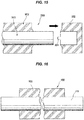
axial core member 101 is brought into press-contact with the supportingportions thin burrs 102a from being generated, as illustrated inFIG. 19 , theaxial core member 101 is deformed by the mold clamping load between thefirst split mold 201 and thesecond split mold 202, and bitten between the parting surfaces of thefirst split mold 201 and thesecond split mold 202, which formsprotrusions die 200 from being tightened and easily creates the gaps δ1, δ2 between the parting surfaces. For this reason, as illustrated inFIG. 20 ,thin plate burrs axial core member 101 and the outer circumferential surface of theroller body 102 are formed. As a result, not only a deburring step is still necessary, but also the die 200 may be damaged by repeatedly biting theaxial core member 101. - The present invention has been made in view of the above points, and an object of the present invention is to prevent thin burrs from being generated and a die from being damaged, in molding a roller including a roller body integrally provided on the outer periphery of an axial core member.
- As means for effectively solving the technical problem mentioned above, a die for molding a roller according to the invention defined in
claim 1 includes a first split mold and a second split mold which are capable of contacting and separating on parting surfaces opposed to each other, and the first split mold and the second split mold are formed with: support portions capable of supporting an axial core member of the roller and closely contacting an outer circumferential surface of the axial core member at an appropriate surface pressure at the time of mold clamping; roller body molding surfaces that define a cavity between the axial core member and the roller body molding surfaces at the time of mold clamping; and recesses located at both end portions of each of the support portions and extending along the parting surfaces, not in contact with the outer circumferential surface of the axial core member at the time of mold clamping, and penetrating the supporting portions. - In the above configuration, when the axial core member of the roller is positioned and disposed between the first split mold and the second split mold and mold clamped, the axial core member is supported in a close contact state between the support portions, and a cavity is defined between the axial core member and the roller body molding surfaces. At this time, a portion of the axial core member supported between the support portions of the first split mold and the second split mold is subject to compressive force due to mold clamping. However, since recesses are formed at both end portions of the support portions, the recesses extending along the parting surfaces of the first split mold and the second split mold, and are not in contact with the outer circumferential surface of the axial core member at the time of mold clamping, the outer circumferential surface of the axial core member is prevented from being bitten between the end portions of the support portions, so that the first split mold and the second split mold are not obstructed from being closed. Therefore, the parting surfaces of the first split mold and the second split mold are brought into close contact with each other. In the step of injecting the uncrosslinked liquid rubber composition into the cavity and crosslinking and curing the liquid rubber composition to integrally mold the roller body on the axial core member, since the support portions of the first split mold and the second split mold and the outer circumferential surface of the axial core member are in close contact with each other, the liquid rubber composition is prevented from permeating therebetween and forming the thin burr, and the liquid rubber composition is also prevented from permeating between the parting surfaces and forming the thin burr.
- The die for molding the roller according to the invention defined in
claim 2 is that, in the configuration described inclaim 1, the first split mold and the second split mold are formed with tear-off portion molding surfaces located on the opposite side to the roller body molding surfaces interposing the support portions and that define a tear-off portion molding space between the axial core member and the tear-off portion molding surfaces at the time of mold clamping. - In the above configuration, in the step of integrally molding the roller body on the axial core member, the uncrosslinked liquid rubber composition injected into the cavity defined between the axial core member and the roller body molding surfaces by mold clamping flows between the tear-off portion molding space defined between the axial core member and the tear-off portion molding surfaces and the cavity, through the recesses formed to the support portions therebetween as the gate. Hence, gate burrs continuous with the roller body are formed in the gate and the tear-off portion is formed in the tear-off portion molding space by curing the liquid rubber composition. This allows the gate burrs to be torn off together with the tear-off portion after the die is opened.
- The die for molding the roller according to the invention defined in
claim 3 is that, in the configuration described inclaim - In the above-described configuration, the outer circumferential surface of the axial core member is made to closely contact the support portions of the first split mold and the second split mold in a state in which the annular projection is appropriately compressed in the radial direction, thereby enabling the close contact surface pressure to be heightened and permeation of the liquid rubber composition to be favorably sealed, and the load of the first split mold and the second split mold due to mold clamping to be reduced by compressive deformation of the annular projection.
- The die for molding the roller according to the invention defined in claim 4 is that, in the configuration described in
claim - In the above-described configuration, since the support portions formed in the first split mold and the second split mold are formed by arc shape projections, the range of contact with the axial core member is limited with respect to the axial direction, thereby enabling the close contact surface pressure to the axial core member to be heightened and permeation of the liquid rubber composition to be favorably sealed.
- According to the die for molding of the roller of the present invention, in molding a roller including a roller body integrally provided on the outer periphery of an axial core member, the outer circumferential surface of the axial core member is prevented from being bitten between the parting surfaces of the first split mold and the second split mold at the time of mold clamping, a thin burr is prevented from being formed between the outer circumferential surface of the axial core member and the support portions of the first split mold and the second split mold, and between the parting surfaces, and damage to the first split mold and the second split mold due to biting or the like can be effectively prevented.
-
-
FIG. 1 is a partial cross-sectional view illustrating a roller molded in a first embodiment of a die for molding a roller according to the present invention by cutting the roller at a plane passing through the axial center of the roller. -
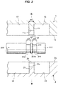
FIG. 2 is a partial cross-sectional view in a separated state, illustrating the first embodiment of the die for molding the roller according to the present invention by cutting the roller at a plane passing through the axial center of a cavity. -
FIG. 3 is a partial cross-sectional view in the separated state, illustrating the first embodiment of the die for molding the roller according to the present invention by cutting the roller at a plane passing through line III-III inFIG. 2 and orthogonal to the axial center of the cavity. -
FIG. 4 is a partial cross-sectional view in a mold clamped state, illustrating the first embodiment of the die for molding the roller according to the present invention by cutting the roller at a plane passing through the axial center of the cavity. -
FIG. 5 is a partial cross-sectional view in the mold clamped state, illustrating the first embodiment of the die for molding the roller according to the present invention by cutting the roller at a plane passing through line V-V inFIG. 4 and orthogonal to the axial center of the cavity. -
FIG. 6 is a partial cross-sectional view illustrating a molded article in the first embodiment of the die for molding the roller according to the present invention by cutting the molded article at a plane passing through the axial center of the molded article. -
FIG. 7 is a cross-sectional view illustrating the molded article in the first embodiment of the die for molding the roller according to the present invention by cutting the molded article at a plane passing through line VII-VII inFIG. 6 and orthogonal to the axial center of the molded article. -
FIG. 8 is an explanatory view illustrating a step of removing burrs from the molded article in the first embodiment of the die for molding the roller according to the present invention. -
FIG. 9 is a partial cross-sectional view in a separated state, illustrating a second embodiment of a die for molding a roller according to the present invention by cutting the roller at a plane passing through the axial center of a cavity. -
FIG. 10 is a partial cross-sectional view in the separated state, illustrating the second embodiment of the die for molding the roller according to the present invention by cutting the roller at a plane passing through line X-X inFIG. 9 and orthogonal to the axial center of the cavity. -
FIG. 11 is a partial cross-sectional view in a mold clamped state, illustrating the second embodiment of the die for molding the roller according to the present invention by cutting the roller at a plane passing through the axial center of the cavity. -
FIG. 12 is a partial cross-sectional view in the mold clamped state, illustrating the second embodiment of the die for molding the roller according to the present invention by cutting the roller at a plane passing through line XII-XII inFIG. 11 and orthogonal to the axial center of the cavity. -
FIG. 13 is a partial cross-sectional view illustrating a molded article in the second embodiment of the die for molding the roller according to the present invention by cutting the molded article at a plane passing through the axial center of the molded article. -
FIG. 14 is a cross-sectional view illustrating the molded article in the second embodiment of the die for molding the roller according to the present invention by cutting the molded article at a plane passing through line XIV-XIV inFIG. 13 and orthogonal to the axial center of the molded article. -
FIG. 15 is an explanatory view illustrating a step of removing burrs from the molded article in the second embodiment of the die for molding the roller according to the present invention. -
FIG. 16 is a partial cross-sectional view illustrating the roller having a structure in which the roller body made of a rubber-like elastic material is integrally molded on the outer periphery of the axial core member, by cutting the roller at a plane passing through the axial center of the roller. -
FIG. 17 is a partial cross-sectional view in a mold clamped state, illustrating an example of a die for molding a roller in a conventional technique, by cutting the die at a plane passing through the axial center of a cavity. -
FIG. 18 is a partial cross-sectional view illustrating a molded article formed by the die for molding the roller in a conventional technique by cutting the molded article at a plane passing through the axial center of the molded article. -
FIG. 19 is a partial cross-sectional view illustrating a state in which a gap is created between parting surfaces in a conventional technique, by cutting at a plane orthogonal to the axial center. -
FIG. 20 is a partial cross-sectional view illustrating a state in which a thin burr is created due to the gap created between the parting surfaces in a conventional technique, by cutting at a plane orthogonal to the axial center. - Preferred embodiments of a die for molding a roller according to the present invention will be described hereinafter with reference to the drawings. Firstly,
FIGS.1 to 8 illustrate a first embodiment. -
FIG. 1 illustrates aroller 300 which is molded using a die according to the first embodiment and is used as an image forming roller, a pressurizing roller, or the like in a printer, a copying machine, or the like, for example. Theroller 300 has a structure in which aroller body 320 made of a rubber-like elastic material is integrally molded on the outer periphery of a metalaxial core member 310 serving as a rotating shaft. Anannular projection 311 located at one end in the axial direction of theroller body 320 is formed on an outercircumferential surface 310a of theaxial core member 310. - As illustrated in
FIGS. 2 and3 , the die according to the first embodiment for molding the above-describedroller 300 includes afirst split mold 1 and asecond split mold 2 capable of contacting and separating onparting surfaces parting surfaces first split mold 1 and thesecond split mold 2 are provided with: supportportions circumferential surface 311 a of theannular projection 311 of theaxial core member 310, at an appropriate surface pressure, in other words, with a proper interference at the time of mold clamping illustrated inFIGS. 4 and 5 ; rollerbody molding surfaces axial core member 310 and the roller body molding surfaces at the time of mold clamping; and tear-offportion molding surfaces body molding surfaces support portions axial end 312 of theaxial member 310 and the tear-off portion molding surfaces at the time of mold clamping, respectively. - At both ends of each of the
support portions recesses support portions parting surfaces circumferential surface 311a of theannular projection 311 of theaxial core member 310 at the time of mold clamping, and defining semicircular gates C as illustrated inFIG. 5 with the outercircumferential surface 311a of theannular projection 311. -
Annular grooves annular projection 311 in theaxial core member 310 in the axial direction, in other words, theannular projection 311 is formed as a relative protrusion between theannular grooves annular projection 311 becomes narrower in width in the axial direction toward the outer diameter side so that theannular projection 311 is easily compressed and deformed when tightened between thesupport portions first split mold 1 and thesecond split mold 2, and in width w1 in the axialdirection support portions annular grooves circumferential surface 311a of theannular projection 311. - In order to form the
roller 300 ofFIG. 1 by using the die according to the first embodiment including the configuration as described above, firstly, as illustrated inFIGS. 2 and3 , theaxial core member 310 is inserted between thefirst split mold 1 and thesecond split mold 2 separated from each other, and is positioned such that oneaxial end 312 thereof is located between the tear-off portion molding surfaces 13, 23 and theannular projection 311 is located between thesupport portions axial core member 310 is placed on thesupport portion 21 of thesecond split mold 2 to be mold lamped. The mold clamping, as illustrated inFIGS. 4 and 5 , brings the innercircumferential surfaces support portions circumferential surface 311 a of theannular projection 311 at an appropriate surface pressure, such that theaxial core member 310 is supported and fixed between thefirst split mold 1 and thesecond split mold 2 and the cylindrical cavity A is defined between the outer circumferential surface of theaxial core member 310 and the roller body molding surfaces 12, 22, and a tear-off portion molding space B is defined between oneaxial end 312 in the axial direction of theaxial core member 310 and the tear-off portion molding surfaces 13, 23. - At this time, end surfaces of the
support portions annular grooves support portions annular grooves - The
annular projection 311 of theaxial core member 310 is subject to compressive deformation due to mold clamping between thesupport portion 11 of thefirst split mold 1 and thesupport portion 21 of thesecond split mold 2. However, sincerecesses support portions circumferential surface 311a of theannular projection 311 of theaxial core member 310 at the time of mold clamping, the outercircumferential surface 311a of theannular projection 311 is prevented from being bitten between the end portions of thesupport portions 11, 21 (between the partingsurfaces first split mold 1 and thesecond split mold 2 are therefore not obstructed from being closed, and the parting surfaces 1a, 2a are brought into close contact with each other. - Further, since the axial width of the
annular projection 311 becomes narrower toward the outer diameter side, deformation due to mold clamping mainly occurs on theannular projection 311 side, and damage to thesupport portions 11, 21 (thefirst split mold 1 and the second split mold 2) is suppressed. In addition, since in width w1 in the axial direction of thesupport portions annular grooves circumferential surface 311a of theannular projection 311, slight misalignment is allowable in placing theaxial core member 310 between thefirst split mold 1 and thesecond split mold 2. - Next, for example, an uncrosslinked liquid rubber composition is injected into the die through an injection port (not illustrated) opened in the tear-off portion molding space B. The liquid rubber composition passes from the tear-off portion molding space B through the semicircular shaped gates C defined between the
recesses support portions circumferential surface 311 a of theannular projection 311, and fills inside the cavity A to be shaped. Then, the liquid rubber composition in the cavity A is crosslinked and cured, so that theroller body 320 integrated with theaxial core member 310 is molded as illustrated inFIGS. 6 and 7 . The liquid rubber composition in the gates C is crosslinked and cured, so that gate burrs 321 continuous with theroller body 320 are molded as illustrated inFIG. 7 . The liquid rubber composition in the tear-off portion molding space B is also crosslinked and cured, so that a tear-offportion 322 continuous with the gate burrs 321 is molded as illustrated inFIGS. 6 and 7 . In addition, the liquid rubber composition is crosslinked and cured between theannular grooves support portions annular rims FIG. 6 are molded. - At this time, as illustrated in
FIGS. 4 and 5 described above, since the outercircumferential surface 311a of theannular projection 311 and the innercircumferential surfaces support portions - Then, after opening the die by separating the
first split mold 1 and thesecond split mold 2 from each other and taking out the molded article illustrated inFIGS. 6 and 7 , the tear-offportion 322 is torn off by hand or the like, as illustrated inFIG. 8 . Theannular rim 324 and the gate burrs 321 which are continuous with the tear-offportion 322 are also torn off with the tear-offportion 322, enabling deburring to be performed easily, and theroller 300 as a product is obtained. - Although the
annular rim 323 which is continuous with theroller body 320 remains even after the deburring, theannular rim 323 is formed relatively thick with theannular groove 313 of theaxial core member 310, and is not a thin burr. Therefore, when theroller 300 is used as an image forming roller, a pressurizing roller, or the like in a copying machine or the like, theannular rim 323 will not fall off from theaxial core member 310 and will not be a foreign object. Thus, theannular rim 323 may be made less liable to fall off by making theannular groove 313 deeper to thereby make theannular rim 323 thicker. - Next,
FIGS. 9 to 15 illustrate a second embodiment of a die for molding a roller according to the present invention. - The second embodiment is different from the above-described first embodiment in that an
axial core member 310 has a simple cylindrical shape andsupport portions first split mold 1 and asecond split mold 2 has a shape in which in width w1 in the axial direction decreases toward the inner diameter side in the vicinity of the inner diameter portion of the molds.Recesses support portions parting surfaces respective support portions circumferential surface 310a of theaxial core member 310 at the time of mold clamping, and defines semicircular gates C as illustrated inFIG. 12 with the outercircumferential surface 310a of theaxial core member 310. The other parts can basically be configured similarly to the first embodiment. - Molding by using the die according to the second embodiment including the configuration as described above is basically similar to the case according to the first embodiment. Specifically, first, as illustrated in
FIGS. 9 and10 , theaxial core member 310 is inserted between thefirst split mold 1 and thesecond split mold 2 separated from each other, and is positioned such that oneaxial end 312 of the axial core member is located between the tear-off portion molding surfaces 13, 23. Then, theaxial core member 310 is placed on thesupport portion 21 of thesecond split mold 2 to be mold clamped. The mold clamping, as illustrated inFIGS. 11 and 12 , brings the innercircumferential surfaces support portions circumferential surface 310a of theaxial core member 310 at an appropriate surface pressure, such that theaxial core member 310 is supported and fixed between thefirst split mold 1 and thesecond split mold 2 and the cylindrical cavity A is defined between the outercircumferential surface 310a of theaxial core member 310 and the roller body molding surfaces 12, 22, and a tear-off portion molding space B is defined between oneaxial end 312 of theaxial core member 310 and the tear-off portion molding surfaces 13, 23. - At this time, a portion of the
axial core member 310, which is fixed between thesupport portion 11 of thefirst split mold 1 and thesupport portion 21 of thesecond split mold 2, is subject to compressive force due to mold clamping. However, sincerecesses support portions circumferential surface 310a of theaxial core member 310 at the time of mold clamping, the outercircumferential surface 310a of theaxial core member 310 is prevented from being bitten between the end portions of thesupport portions 11, 21 (between the partingsurfaces first split mold 1 and thesecond split mold 2 are therefore not obstructed from being closed, and the parting surfaces 1a, 2a are brought into close contact with each other. - In addition, the
support portions first split mold 1 and thesecond split mold 2 are formed such that the vicinity of the inner diameter portion thereof has a shape in which in width w1 in the axial direction decreases toward the inner diameter side, and therefore thesupport portions circumferential surface 310a of theaxial core member 310. - Next, for example, an uncrosslinked liquid rubber composition is injected into the die through an injection port (not illustrated) opened in the tear-off portion molding space B. The liquid rubber composition passes from the tear-off portion molding space B through the semicircular shaped gates C defined between the
recesses support portions circumferential surface 310a of theaxial core member 310, and fills inside the cavity A to be shaped. Then, the liquid rubber composition in the cavity A is crosslinked and cured, so that theroller body 320 integrated with theaxial core member 310 is molded as illustrated inFIGS. 13 and 14 . The liquid rubber composition in the gates C is crosslinked and cured, so that gate burrs 321 continuous with theroller body 320 is molded as illustrated inFIG. 14 . The liquid rubber composition in the tear-off portion molding space B is also crosslinked and cured, so that a tear-offportion 322 continuous with the gate burrs 321 is molded as illustrated inFIGS. 13 and 14 . - At this time, as illustrated in
FIGS. 11 and 12 described above, since the outercircumferential surface 310a of theaxial core member 310 and the innercircumferential surfaces support portions - Then, after opening the die by separating the
first split mold 1 and thesecond split mold 2 from each other and taking out the molded article illustrated inFIGS. 13 and 14 , the tear-offportion 322 is torn off by hand or the like, as illustrated inFIG. 15 . The gate burrs 321 which is continuous with the tear-offportion 322 are also torn off with the tear-offportion 322, enabling deburring to be performed easily. -
- 1 First split mold
- 2 Second split mold
- 1a, 2a Parting surface
- 11, 21 Support portion
- 12, 22 Roller body molding surface
- 13, 23 Tear-off portion molding surface
- 14, 24 Recess
- 300 Roller
- 310 Axial core member
- 311 Annular projection
- 320 Roller body
- 321 Gate burr
- 322 Tear-off portion
- A Cavity
- B Tear-off portion molding space
- C Gate
Claims (4)
- A die for molding a roller comprising:a first split mold and a second split mold which are capable of contacting and separating on parting surfaces opposed to each other;support portions capable of supporting an axial core member of the roller and closely contacting an outer circumferential surface of the axial core member at an appropriate surface pressure at the time of mold clamping;roller body molding surfaces that define a cavity between the axial core member and the roller body molding surfaces at the time of mold clamping;recesses located at both end portions of each of the support portions and extending along the parting surfaces, not in contact with the outer circumferential surface of the axis core member at the time of mold clamping, and penetrating the supporting portions; andthe support portions, the roller body molding surfaces and the recess being formed in the first split mold and the second split mold.
- The die for molding the roller according to claim 1, wherein the first split mold and the second split mold are formed with tear-off portion molding surfaces located on the opposite side to the roller body molding surfaces interposing the support portions and that define a tear-off portion molding space between the axial core member and the tear-off portion molding surfaces at the time of mold clamping.
- The die for molding the roller according to claim 1 or 2, wherein
the axial core member is formed with a ring-shaped annular projection, and
an outer circumferential surface of the annular projection is in close contact with the support portions in a state appropriately compressed in a radial direction. - The die for molding the roller according to claim 1 or 2, wherein each of the support portions is formed with an arc shape projection.
Applications Claiming Priority (2)
| Application Number | Priority Date | Filing Date | Title |
|---|---|---|---|
| JP2014248971A JP2016107561A (en) | 2014-12-09 | 2014-12-09 | Die for molding roll |
| PCT/JP2015/081427 WO2016092998A1 (en) | 2014-12-09 | 2015-11-09 | Die for molding roller |
Publications (2)
| Publication Number | Publication Date |
|---|---|
| EP3231570A1 true EP3231570A1 (en) | 2017-10-18 |
| EP3231570A4 EP3231570A4 (en) | 2017-11-29 |
Family
ID=56107193
Family Applications (1)
| Application Number | Title | Priority Date | Filing Date |
|---|---|---|---|
| EP15866798.0A Withdrawn EP3231570A4 (en) | 2014-12-09 | 2015-11-09 | Die for molding roller |
Country Status (5)
| Country | Link |
|---|---|
| US (1) | US20170326759A1 (en) |
| EP (1) | EP3231570A4 (en) |
| JP (1) | JP2016107561A (en) |
| CN (1) | CN107073763A (en) |
| WO (1) | WO2016092998A1 (en) |
Families Citing this family (3)
| Publication number | Priority date | Publication date | Assignee | Title |
|---|---|---|---|---|
| JP6657274B2 (en) * | 2018-02-07 | 2020-03-04 | バンドー化学株式会社 | Weight roller, method for manufacturing the same, and mold used for manufacturing the weight roller |
| CN112045941B (en) * | 2019-06-06 | 2022-06-21 | 河南裕展精密科技有限公司 | Injection mould |
| CN111685716B (en) * | 2020-07-24 | 2022-03-22 | 湖南省华芯医疗器械有限公司 | Endoscope front end assembly, endoscope and production mold |
Family Cites Families (14)
| Publication number | Priority date | Publication date | Assignee | Title |
|---|---|---|---|---|
| JPS61182917A (en) * | 1985-02-12 | 1986-08-15 | Canon Inc | Molding method |
| JPH0624733B2 (en) * | 1986-05-16 | 1994-04-06 | キヤノン株式会社 | Rubber roller and method for producing the same |
| JPH07100330B2 (en) * | 1987-11-20 | 1995-11-01 | キヤノン株式会社 | Method for manufacturing conductive elastic roller |
| JP3483392B2 (en) * | 1996-04-22 | 2004-01-06 | キヤノン株式会社 | Roller manufacturing method and manufacturing apparatus using the same |
| JP3302261B2 (en) * | 1996-06-04 | 2002-07-15 | キヤノン株式会社 | Roller manufacturing method and manufacturing apparatus |
| IT1294485B1 (en) * | 1997-08-22 | 1999-04-12 | Celestino Niccolai | PROCEDURE AND EQUIPMENT FOR FORMING A COATING ON A ROD ELEMENT, SUCH AS A BROOM HANDLE |
| JP3733223B2 (en) * | 1997-10-21 | 2006-01-11 | キヤノン株式会社 | Roller manufacturing method |
| JP3449402B2 (en) * | 1998-06-29 | 2003-09-22 | 住友ゴム工業株式会社 | Injection mold |
| CN2399188Y (en) * | 1999-11-23 | 2000-10-04 | 北京天宝办公设备配件厂 | Fluorine coated silastic pressure roller shaping mould |
| JP2001239553A (en) * | 2000-02-28 | 2001-09-04 | Bridgestone Corp | Mold and method for manufacturing molded object using it |
| JP3971926B2 (en) * | 2002-01-08 | 2007-09-05 | キヤノン化成株式会社 | Manufacturing method of rubber roller |
| JP4558444B2 (en) * | 2004-10-20 | 2010-10-06 | キヤノン化成株式会社 | Foaming roller manufacturing method, molding die and liquid receiving cup heating apparatus and heating method |
| JP2007152893A (en) * | 2005-12-08 | 2007-06-21 | Bridgestone Corp | Roller mold and method of manufacturing roller using the same |
| JP2008080593A (en) * | 2006-09-27 | 2008-04-10 | Swcc Showa Device Technology Co Ltd | Manufacturing apparatus of highly heat-conductive rubber roller |
-
2014
- 2014-12-09 JP JP2014248971A patent/JP2016107561A/en not_active Withdrawn
-
2015
- 2015-11-09 EP EP15866798.0A patent/EP3231570A4/en not_active Withdrawn
- 2015-11-09 US US15/529,919 patent/US20170326759A1/en not_active Abandoned
- 2015-11-09 WO PCT/JP2015/081427 patent/WO2016092998A1/en not_active Ceased
- 2015-11-09 CN CN201580052223.5A patent/CN107073763A/en active Pending
Also Published As
| Publication number | Publication date |
|---|---|
| US20170326759A1 (en) | 2017-11-16 |
| CN107073763A (en) | 2017-08-18 |
| WO2016092998A1 (en) | 2016-06-16 |
| EP3231570A4 (en) | 2017-11-29 |
| JP2016107561A (en) | 2016-06-20 |
Similar Documents
| Publication | Publication Date | Title |
|---|---|---|
| US10293532B2 (en) | Method for producing roller member, roller-member mold, roller shaft, and roller member | |
| US20170326759A1 (en) | Die for molding roller | |
| US11440226B2 (en) | Compression vulcanization molding mold for rolling bearing seal, and method for manufacturing rolling bearing seal | |
| JP2015073406A (en) | Stator molding method and molding apparatus | |
| JP2007159245A (en) | Mold for use in manufacturing rotor of motor | |
| JP4632073B2 (en) | Mold for sealing ring molding and molding method for sealing ring | |
| CN114269541B (en) | Method for manufacturing double-ring type resin retainer | |
| EP2053288A2 (en) | Oil seals | |
| JP2009074642A (en) | Manufacturing method of sealing device | |
| JP5629988B2 (en) | Bearing device with pulley | |
| JP6743201B2 (en) | Roller members, copiers, and printers | |
| CN112571727B (en) | Molded article, electric motor, device and method for manufacturing molded article | |
| JP2010019342A (en) | Manufacturing method of tube type vibration-proofing bush and tube type vibration-proofing bush manufactured thereby | |
| US10683892B2 (en) | Bearing unit structure and manufacturing method thereof | |
| JPH11240026A (en) | Metal-rubber composite member and method of manufacturing the same | |
| JP2025099776A (en) | Vibration control device and manufacturing method therefor | |
| JP2007100905A (en) | Self-aligning slide bearing and its outer ring manufacturing method | |
| JP4092534B2 (en) | Annular member mounted around shaft and recording apparatus including the annular member | |
| JPH0586518U (en) | Ring member resin molding equipment | |
| JP3873196B1 (en) | Anti-vibration device manufacturing method | |
| JPH05269791A (en) | Production of resin molded product having insert metal | |
| JP5290933B2 (en) | Anti-vibration bush manufacturing method and intermediate cylinder drawing apparatus | |
| JP2007020321A (en) | Stator core positioning device and method | |
| JP2024128879A (en) | Assembly and manufacturing method thereof | |
| JPH023860Y2 (en) |
Legal Events
| Date | Code | Title | Description |
|---|---|---|---|
| PUAI | Public reference made under article 153(3) epc to a published international application that has entered the european phase |
Free format text: ORIGINAL CODE: 0009012 |
|
| 17P | Request for examination filed |
Effective date: 20170606 |
|
| AK | Designated contracting states |
Kind code of ref document: A1 Designated state(s): AL AT BE BG CH CY CZ DE DK EE ES FI FR GB GR HR HU IE IS IT LI LT LU LV MC MK MT NL NO PL PT RO RS SE SI SK SM TR |
|
| AX | Request for extension of the european patent |
Extension state: BA ME |
|
| A4 | Supplementary search report drawn up and despatched |
Effective date: 20171026 |
|
| RIC1 | Information provided on ipc code assigned before grant |
Ipc: B29C 45/00 20060101ALI20171020BHEP Ipc: B29C 39/26 20060101AFI20171020BHEP Ipc: G03G 15/00 20060101ALI20171020BHEP Ipc: G03G 15/20 20060101ALI20171020BHEP Ipc: B29C 39/28 20060101ALI20171020BHEP Ipc: B29C 33/12 20060101ALI20171020BHEP Ipc: B29C 39/10 20060101ALI20171020BHEP Ipc: B29C 45/26 20060101ALI20171020BHEP Ipc: B29C 45/14 20060101ALI20171020BHEP |
|
| DAV | Request for validation of the european patent (deleted) | ||
| DAX | Request for extension of the european patent (deleted) | ||
| STAA | Information on the status of an ep patent application or granted ep patent |
Free format text: STATUS: THE APPLICATION IS DEEMED TO BE WITHDRAWN |
|
| 18D | Application deemed to be withdrawn |
Effective date: 20180525 |