EP3231561A1 - Work bench - Google Patents
Work bench Download PDFInfo
- Publication number
- EP3231561A1 EP3231561A1 EP15867093.5A EP15867093A EP3231561A1 EP 3231561 A1 EP3231561 A1 EP 3231561A1 EP 15867093 A EP15867093 A EP 15867093A EP 3231561 A1 EP3231561 A1 EP 3231561A1
- Authority
- EP
- European Patent Office
- Prior art keywords
- worktable
- board
- supporting
- base board
- coupled
- Prior art date
- Legal status (The legal status is an assumption and is not a legal conclusion. Google has not performed a legal analysis and makes no representation as to the accuracy of the status listed.)
- Granted
Links
Images

Classifications
-
- B—PERFORMING OPERATIONS; TRANSPORTING
- B25—HAND TOOLS; PORTABLE POWER-DRIVEN TOOLS; MANIPULATORS
- B25H—WORKSHOP EQUIPMENT, e.g. FOR MARKING-OUT WORK; STORAGE MEANS FOR WORKSHOPS
- B25H1/00—Work benches; Portable stands or supports for positioning portable tools or work to be operated on thereby
- B25H1/02—Work benches; Portable stands or supports for positioning portable tools or work to be operated on thereby of table type
-
- B—PERFORMING OPERATIONS; TRANSPORTING
- B25—HAND TOOLS; PORTABLE POWER-DRIVEN TOOLS; MANIPULATORS
- B25H—WORKSHOP EQUIPMENT, e.g. FOR MARKING-OUT WORK; STORAGE MEANS FOR WORKSHOPS
- B25H1/00—Work benches; Portable stands or supports for positioning portable tools or work to be operated on thereby
- B25H1/02—Work benches; Portable stands or supports for positioning portable tools or work to be operated on thereby of table type
- B25H1/04—Work benches; Portable stands or supports for positioning portable tools or work to be operated on thereby of table type portable
-
- B—PERFORMING OPERATIONS; TRANSPORTING
- B25—HAND TOOLS; PORTABLE POWER-DRIVEN TOOLS; MANIPULATORS
- B25H—WORKSHOP EQUIPMENT, e.g. FOR MARKING-OUT WORK; STORAGE MEANS FOR WORKSHOPS
- B25H1/00—Work benches; Portable stands or supports for positioning portable tools or work to be operated on thereby
- B25H1/08—Work benches; Portable stands or supports for positioning portable tools or work to be operated on thereby with provision for attachment of work holders
-
- B—PERFORMING OPERATIONS; TRANSPORTING
- B25—HAND TOOLS; PORTABLE POWER-DRIVEN TOOLS; MANIPULATORS
- B25H—WORKSHOP EQUIPMENT, e.g. FOR MARKING-OUT WORK; STORAGE MEANS FOR WORKSHOPS
- B25H1/00—Work benches; Portable stands or supports for positioning portable tools or work to be operated on thereby
- B25H1/14—Work benches; Portable stands or supports for positioning portable tools or work to be operated on thereby with provision for adjusting the bench top
- B25H1/16—Work benches; Portable stands or supports for positioning portable tools or work to be operated on thereby with provision for adjusting the bench top in height
-
- B—PERFORMING OPERATIONS; TRANSPORTING
- B28—WORKING CEMENT, CLAY, OR STONE
- B28D—WORKING STONE OR STONE-LIKE MATERIALS
- B28D7/00—Accessories specially adapted for use with machines or devices of the preceding groups
-
- B—PERFORMING OPERATIONS; TRANSPORTING
- B28—WORKING CEMENT, CLAY, OR STONE
- B28D—WORKING STONE OR STONE-LIKE MATERIALS
- B28D7/00—Accessories specially adapted for use with machines or devices of the preceding groups
- B28D7/04—Accessories specially adapted for use with machines or devices of the preceding groups for supporting or holding work or conveying or discharging work
-
- B—PERFORMING OPERATIONS; TRANSPORTING
- B28—WORKING CEMENT, CLAY, OR STONE
- B28D—WORKING STONE OR STONE-LIKE MATERIALS
- B28D1/00—Working stone or stone-like materials, e.g. brick, concrete or glass, not provided for elsewhere; Machines, devices, tools therefor
- B28D1/02—Working stone or stone-like materials, e.g. brick, concrete or glass, not provided for elsewhere; Machines, devices, tools therefor by sawing
Definitions
- This invention consists therefore in a worktable specially applicable to facilitate cutting large-sized porcelain articles without discarding other types of materials, being for that aim structurally designed with different boards in hinged connection to a basic board, which are arranged supported on cushioning elements accompanying all the time the segment of the piece to be cut, avoiding undesirable breakages.
- the field of application of this invention is within the sector of the industry engaged in manufacturing worktables, in particular focused in the area of the tables for cutting flat pieces to work with large-sized porcelain materials or the like
- the flat pieces of porcelain material as well as also others of other materials such as glass, ceramic, or others use to be cut with a cutting tool that produces a mark or notch on the surface of the piece and thereafter slightly hitting or pressing the segment to be cut, normally placing it on the edge of the worktable to eventually breaking the piece just by the line that has been marked by the cutting machine.
- the objective of this invention therefore is to develop a worktable that allows to facilitate the described operation and make sure to achieve a perfect cut of the pieces just by the notch the tool will mark, in every and each case, avoiding any suffering of the segments cut, by means of a system of cushioned movable boards that accompany the said segments all the time.
- What the invention proposes is a worktable the essential aim of which is to provide an easy and safe system for cutting pieces of porcelain or of other similar materials, in particular in order that, after the cutting machine produces the notch marking the breaking line, to procure accompaniment to the segment to be cut supported all the time and throughout it on a cushioned supporting surface while pressure is applied on it to achieve the material breaking exactly by the said line.
- the worktable of the invention is essentially configured from a base board supported on fixed legs, that can preferably be height-regulable to situate the table at the required height and a series of supporting boards , at least one joined coplanar to the base board in a hinged and cushioned way, so that, when pressure is applied on them, they have the capability to be downwards folded to a certain extent, tending to return to their horizontal position thanks to the said cushioning means.
- the said supporting boards are used to place the pieces with the cutting line on their point of hinged connection to the base board and with the part of the segment to be split or broken arranged on them, while the rest of the piece rests on the base board. And when the piece is placed in the said position, a pressure can be exercised on the part of the segment to be cut being assured that the said pressure is correctly distributed as the full piece is supported on a surface accompanying the segment.
- a first supporting board is coupled to the base board on one of its sides, a second supporting board in another of its sides, concretely on the side adjacent to the one being coupled to the first supporting board, and a third supporting board that, instead of being coupled to the base board, is coupled between the first and the second supporting boards, the said hinged connection being selectively with one or the other, by incorporating a link rod linking them to each other, providing thus the possibility to extend the surface of the table that constitutes a fixed board or a moving board and thus adapting it to the different needs.
- the cushioning means providing that the accompaniment of the supporting boards and their return to their initial position are formed by spring-loaded legs, which in addition are provided with fastening means to avoid or not, as required, their use as a cushioning element.
- the said legs are incorporated, at least, one under the different supporting boards and, depending whether they have to be used or not, they are left unfastened in order that the spring they incorporate acts or they are fastened in order they do not act and serve as fixed legs.
- the supporting boards are coupled quickly and easy removable to the rims of the base board of the table, by using tongue and groove connecting hinges, so that the full assembly can be easily coupled and allows a way for dismounting the table for its transport and transfer, the legs being also preferably dismountable, as well those fixed of the base board as those cushioned of the supporting boards.
- the boards can be replaced by a series of strips in a parallel arrangement offering as a whole a surface on which the material to be cut is supported.
- the surface shows one or several lengthwise and/or crosswise slots to insert buffer stops to position the pieces or the cutting machine.
- the disclosed worktable consists, therefore, of an innovating structure having characteristics unknown up to date for the purpose to which it is designed, reasons that, jointly with its practical utility, provide it with sufficient ground to obtain the privilege of exclusivity applied for.
- the table (1) in question is essentially configured by a base board (2) having a rectangular plan supported on fixed legs (3), preferably four legs, or that can be height-regulable, to which in an innovating way is coupled, at least, a first supporting board (4) that is joined laterally to one of the sides of the said base board (2) hinged and cushioned, that means, so that it has the capability to be downwards folded to a certain extent, when applying pressure on the said supporting board (4) tending to return to its horizontal position and coplanar to the base board (2) when such pressure is no longer exercised, for which an hinged connection through hinges (5, 6) and cushioning means (7) is contemplated.
- a second supporting board (4') is coupled to the base board (2) in another of its sides, concretely in the side adjacent to that the first supporting board (4) is coupled, in both cases with the same hinged connection system and cushioned by means of hinges (5, 6) and cushioning means (7), and there also exists a third supporting board (4") that is coupled to the first and to the second supporting boards (4, 4') also by means of hinges (5, 6) and cushioning means, but including a linking part (8) that, preferably consisting of a rod, allows its hinging or movement in conjunction with one or the other, selectively.
- link rod (8) visible in the figure 15 and designed to be inserted in holes (9) provided to that effect in coinciding points of the rims of the structure of the supporting boards that remain facing each other, as it can be seen in the Figures 7 and 11 , allows, depending if it is placed between the first supporting board (4) and the third supporting board (4"), or between the second supporting board (4') and the third supporting board (4"), to extend the surface of the supporting board that is hinged with the base board (2) and with the other supporting board, on one side or the other thereof as required.
- the cushioning means (7) that determine the supporting boards (4, 4', 4") tending to return to their horizontal position, coplanar to the base board (2) preferably consist of cushioned legs that, formed by two independent stretches (10) house a spring (11) within them, fastened to a support (12) which, in addition, are provided with fastening means (13) to avoid the movement of the said spring (11), for example a pin (13) that locks both stretches (10) of the leg.
- the hinges (5, 6) that join in an hinged connection the supporting boards (4, 4' 4") to each other and to the base board (2) are preferably easily dismountable, and of tongue and groove coupling type, comprising, as shown in Figures 16 to 19 , female pieces (5) formed by a flatbar with drilled holes (14), in order it is screwed on the board structure, and a window-shaped hollow (15) ( figures 16 and 18 ), and male pieces (6) formed by another flatbar with drilled holes (14), for screwing it, and a hook-like curved protrusion (16), adapted to be imbedded in the window (15) of the female pieces (5) ( figures 17 and 19 ), so that the said coupling and its dismounting result easy and quick.
- tongue and groove coupling type comprising, as shown in Figures 16 to 19 , female pieces (5) formed by a flatbar with drilled holes (14), in order it is screwed on the board structure, and a window-shaped hollow (15) ( figures 16 and 18 ), and male pieces (6)
- the surface of the base board (2) and of the supporting boards (4, 4', 4"), that is covered with a soft material, of rubber type or the like, has one or several slots (17) running crosswise and/or lengthwise from one end to another end thereof been, if applicable, coincident in position between one and other boards, which are designed to insert buffer stops (18) that, fixed by means of a suitable tightening tool (19), serve to position the pieces to be cut on the table and avoid any undesirable displacement thereof.
Landscapes
- Engineering & Computer Science (AREA)
- Mechanical Engineering (AREA)
- Workshop Equipment, Work Benches, Supports, Or Storage Means (AREA)
- Processing Of Stones Or Stones Resemblance Materials (AREA)
- Re-Forming, After-Treatment, Cutting And Transporting Of Glass Products (AREA)
Abstract
Description
- The invention, as it appears in the title of this specification, refers to a worktable, which presents a series of novelty advantages and characteristics, that will be described in detail below, that mean a significant innovation in the current state of the art.
- This invention consists therefore in a worktable specially applicable to facilitate cutting large-sized porcelain articles without discarding other types of materials, being for that aim structurally designed with different boards in hinged connection to a basic board, which are arranged supported on cushioning elements accompanying all the time the segment of the piece to be cut, avoiding undesirable breakages.
- The field of application of this invention is within the sector of the industry engaged in manufacturing worktables, in particular focused in the area of the tables for cutting flat pieces to work with large-sized porcelain materials or the like
- As it is known, the flat pieces of porcelain material as well as also others of other materials such as glass, ceramic, or others, use to be cut with a cutting tool that produces a mark or notch on the surface of the piece and thereafter slightly hitting or pressing the segment to be cut, normally placing it on the edge of the worktable to eventually breaking the piece just by the line that has been marked by the cutting machine.
- However, this operation, specially when it is dealt with large-sized pieces, for example of 3000 x 1500 cm, is a very delicate and risky operation, because if the break of the segment does not occur accurately on the marked line, the full piece may be damaged and anyway, risks could be run that the segment to be cut is broken when hitting it or when it falls down with the subsequent economic cost for waste of material and the subsequent risk of injuries for the user.
- The objective of this invention therefore is to develop a worktable that allows to facilitate the described operation and make sure to achieve a perfect cut of the pieces just by the notch the tool will mark, in every and each case, avoiding any suffering of the segments cut, by means of a system of cushioned movable boards that accompany the said segments all the time.
- As reference to the current state of the art, it shall be pointed out that, although different models and types of worktables are known in the market, applicable to different uses, some of them designed like the one herein to cut pieces, at least this applicant is not aware of any showing technical and structural characteristics similar to those shown by the table of the invention.
- The table proposed by the invention, is therefore configured as a significant novelty, within its field of application, because by implementing it, the above mentioned objectives are satisfactorily achieved, the characterizing details making it possible and distinguishing it from the already known are conveniently appearing in the final claims attached to this specification.
- What the invention proposes is a worktable the essential aim of which is to provide an easy and safe system for cutting pieces of porcelain or of other similar materials, in particular in order that, after the cutting machine produces the notch marking the breaking line, to procure accompaniment to the segment to be cut supported all the time and throughout it on a cushioned supporting surface while pressure is applied on it to achieve the material breaking exactly by the said line.
- For this, the worktable of the invention is essentially configured from a base board supported on fixed legs, that can preferably be height-regulable to situate the table at the required height and a series of supporting boards , at least one joined coplanar to the base board in a hinged and cushioned way, so that, when pressure is applied on them, they have the capability to be downwards folded to a certain extent, tending to return to their horizontal position thanks to the said cushioning means.
- Thus, the said supporting boards are used to place the pieces with the cutting line on their point of hinged connection to the base board and with the part of the segment to be split or broken arranged on them, while the rest of the piece rests on the base board. And when the piece is placed in the said position, a pressure can be exercised on the part of the segment to be cut being assured that the said pressure is correctly distributed as the full piece is supported on a surface accompanying the segment.
- It shall be pointed out that, although one or several supporting boards can be coupled to the base board, in different options, in a preferred embodiment of the invention, a first supporting board is coupled to the base board on one of its sides, a second supporting board in another of its sides, concretely on the side adjacent to the one being coupled to the first supporting board, and a third supporting board that, instead of being coupled to the base board, is coupled between the first and the second supporting boards, the said hinged connection being selectively with one or the other, by incorporating a link rod linking them to each other, providing thus the possibility to extend the surface of the table that constitutes a fixed board or a moving board and thus adapting it to the different needs.
- On their hand, the cushioning means providing that the accompaniment of the supporting boards and their return to their initial position, in the preferred embodiment of the invention, are formed by spring-loaded legs, which in addition are provided with fastening means to avoid or not, as required, their use as a cushioning element. Thus, the said legs are incorporated, at least, one under the different supporting boards and, depending whether they have to be used or not, they are left unfastened in order that the spring they incorporate acts or they are fastened in order they do not act and serve as fixed legs.
- According to another significant characteristic of the invention, the supporting boards are coupled quickly and easy removable to the rims of the base board of the table, by using tongue and groove connecting hinges, so that the full assembly can be easily coupled and allows a way for dismounting the table for its transport and transfer, the legs being also preferably dismountable, as well those fixed of the base board as those cushioned of the supporting boards.
- In a variant of embodiment, the boards can be replaced by a series of strips in a parallel arrangement offering as a whole a surface on which the material to be cut is supported.
- Last, and in an already known way, the surface shows one or several lengthwise and/or crosswise slots to insert buffer stops to position the pieces or the cutting machine.
- Therefore, the main advantages the table of the invention provides are:
- The horizontal folding system of the supporting boards to facilitate cutting the large-sized porcelain pieces that make a virtually perfect 90-degree cut, as the segment to be cut never lacks the support of the table.
- The cushioned legs to facilitate folding the supporting boards that tends to return to their position after they have been used.
- The multiple assistances to the work such as the slots for the locking toes for the ceramic piece, the supporting boards being converted into extensions of the fixed base board on its sides to allow different positions of the large-sized piece etc.
- The sizes of each of the boards to be used in different combinations. As well lengthwise as crosswise.
- The handling of the table, fully dismountable in a few seconds to facilitate its transport to any work place.
- The support for the cutting machine of different brands existing in the market, to facilitate the work when cutting- separating the material.
- The disclosed worktable consists, therefore, of an innovating structure having characteristics unknown up to date for the purpose to which it is designed, reasons that, jointly with its practical utility, provide it with sufficient ground to obtain the privilege of exclusivity applied for.
- To complement the description that is being carried out and in order to assist to best understand the characteristics of the invention, a set of drawings is attached to this specification as an integral part thereof in which, with illustration and not limiting purpose, the following has been represented:
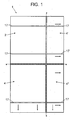
- Figure number 1.- It shows a top plan view of an example of embodiment of the worktable, object of the invention, and the arrangement of the different boards that it includes being apparent;
-
Figures number -
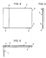
Figures number 4 and 5.- They show each, top plan and side profile views, respectively, of a first supporting board pertaining to the table, according to the example of thefigure 1 ; - Figure number 6.- They shows a side elevation view of the first supporting board appearing in
Figures 4 and 5 , represented in this case with the cushioned leg incorporated at its lower part; -
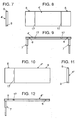
Figures number figure 1 , thefigure 9 showing the elevation view of two cushioned legs it incorporates; -
Figures number figure 1 , thefigure 12 showing the elevation view of the cushioned leg it incorporates; -
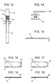
Figure number 13. - It shows a section view of one of the cushioned legs of the invention, according to the example represented in thefigure 1 ; - Figure number 14.- It shows an elevation view of an example of buffer stop to fasten the position of the plates and the tool serving to fasten it in the slots of the table provided to that effect;
- Figure number 15.- It shows an elevation view of a rod serving to lock in order to join to each other the second and third supporting boards of the table, according to the example of the
figure 1 ; and -
Figures number figure 1 . Concretely thefigure 16 and thefigure 18 , respectively, show the plan and elevation views of the female part of the hinge, and theFigures 17 and 19 , respectively, the plan and elevation views of the male part. - At the sight of the said figures, and according to the numbering adopted, an example of a preferred but not limiting embodiment can be seen in them, of the worktable of the invention, which comprises the parts and elements that are indicated and described in detail thereafter.
- Thus, as it can be seen in the
figure 1 , the table (1) in question, is essentially configured by a base board (2) having a rectangular plan supported on fixed legs (3), preferably four legs, or that can be height-regulable, to which in an innovating way is coupled, at least, a first supporting board (4) that is joined laterally to one of the sides of the said base board (2) hinged and cushioned, that means, so that it has the capability to be downwards folded to a certain extent, when applying pressure on the said supporting board (4) tending to return to its horizontal position and coplanar to the base board (2) when such pressure is no longer exercised, for which an hinged connection through hinges (5, 6) and cushioning means (7) is contemplated. - Preferably, in addition, a second supporting board (4') is coupled to the base board (2) in another of its sides, concretely in the side adjacent to that the first supporting board (4) is coupled, in both cases with the same hinged connection system and cushioned by means of hinges (5, 6) and cushioning means (7), and there also exists a third supporting board (4") that is coupled to the first and to the second supporting boards (4, 4') also by means of hinges (5, 6) and cushioning means, but including a linking part (8) that, preferably consisting of a rod, allows its hinging or movement in conjunction with one or the other, selectively.
- Thus, such link rod (8), visible in the
figure 15 and designed to be inserted in holes (9) provided to that effect in coinciding points of the rims of the structure of the supporting boards that remain facing each other, as it can be seen in theFigures 7 and 11 , allows, depending if it is placed between the first supporting board (4) and the third supporting board (4"), or between the second supporting board (4') and the third supporting board (4"), to extend the surface of the supporting board that is hinged with the base board (2) and with the other supporting board, on one side or the other thereof as required. - In the
figure 1 the full table of the said preferred option of embodiment can be seen, with the base board (2) and the three supporting boards (4, 4', 4"), the points of hinged connection where the folds of the said supporting boards are produced been represented by means of a dashed line and their downwards tilting, by means of arrows, the two possibilities it offers been shown as well by one side as by the other, that means, as well lengthwise as crosswise, as required. - And in the
Figures 2 to 12 , the different base (2) and supporting (4, 4' 4") boards can be seen, in different views to allow to appreciate all their characteristics. - As represented in
Figures 6 ,9 ,12 and13 , the cushioning means (7) that determine the supporting boards (4, 4', 4") tending to return to their horizontal position, coplanar to the base board (2), preferably consist of cushioned legs that, formed by two independent stretches (10) house a spring (11) within them, fastened to a support (12) which, in addition, are provided with fastening means (13) to avoid the movement of the said spring (11), for example a pin (13) that locks both stretches (10) of the leg. - On their hand, the hinges (5, 6) that join in an hinged connection the supporting boards (4, 4' 4") to each other and to the base board (2) are preferably easily dismountable, and of tongue and groove coupling type, comprising, as shown in
Figures 16 to 19 , female pieces (5) formed by a flatbar with drilled holes (14), in order it is screwed on the board structure, and a window-shaped hollow (15) (figures 16 and 18 ), and male pieces (6) formed by another flatbar with drilled holes (14), for screwing it, and a hook-like curved protrusion (16), adapted to be imbedded in the window (15) of the female pieces (5) (figures 17 and 19 ), so that the said coupling and its dismounting result easy and quick. - Last, the surface of the base board (2) and of the supporting boards (4, 4', 4"), that is covered with a soft material, of rubber type or the like, has one or several slots (17) running crosswise and/or lengthwise from one end to another end thereof been, if applicable, coincident in position between one and other boards, which are designed to insert buffer stops (18) that, fixed by means of a suitable tightening tool (19), serve to position the pieces to be cut on the table and avoid any undesirable displacement thereof.
- The nature of this invention being sufficiently described, as well as the way of implementing it , it is not deemed necessary to extend any longer the explanation in order that any person skilled in the art understands its scope and the advantages arising from it, and it is stated that, within its essentiality, it can be implemented in other embodiments differing in detail from the one indicated for example purpose and to which shall also extend the protection applied for, provided that its main principle is not altered, changed or modified.
Claims (13)
- Worktable that, specially applicable to facilitate cutting pieces of porcelain or other materials, and configured by a base board (2) of rectangular plan that is supported on fixed legs (3) or height-regulable legs, is characterized in that at least, a first supporting board (4) is coupled to that base board (2) that is laterally hinged to one of its sides with capability to be downwards folded.
- Worktable, according to the claim 1, characterized in that the hinged connection of the supporting board (4) with respect to the base board (2) has cushioning means (7) that allow that the supporting board (4) returns to its horizontal position and coplanar to the base board (2) when pressure is no longer exercised.
- Worktable, according to the claims 1 and 2, characterized in that, in addition, a second supporting board (4') is coupled to the base board (2) in another of its sides, also by means of hinges (5, 6) and cushioning means (7).
- Worktable, according to claims 1 to 3, characterized in that a second supporting board (4') is coupled to the base board (2) in the lateral side adjacent to which the first supporting board (4) is coupled and a third supporting board (4") appears that is coupled to the first and the second supporting boards (4, 4') also by means of hinges (5, 6) and cushioning means (7) and includes a linking part (8) that allows its hinging or movement in conjunction with one or the other, selectively.
- Worktable, according to claim 4, characterized in that the linking part (8) is a rod adapted to be inserted in holes (9) provided to that effect in coinciding points of the rims of the structure of the supporting boards that remain facing each other
- Worktable, according to any of the claims 1 to 5, characterized in that the cushioning means (7) that determine the supporting boards (4, 4', 4") tending to return to their horizontal position, coplanar to the base board (2), consist of cushioned legs housing a spring (11).
- Worktable, according to claim 6, characterized in that the legs comprise two independent stretches (10) housing within them the spring (11) fastened on a support (12).
- Worktable, according to any of the claims 6 and 7, characterized in that the cushioned legs have fastening means (13) to avoid the movement of the spring (11).
- Worktable, according to any of the claims 1 to 6, characterized in that the hinges (5, 6) of hinged connection of the supporting boards (4, 4' 4") to each other and to the base board (2) are dismountable.
- Worktable, according to the claim 9, characterized in that the hinges (5, 6) are of the tongue and groove coupling type.
- Worktable, according to the claim 10, characterized in that the hinges (5, 6) comprise female pieces (5) formed by a flatbar with drilled holes (14), to screw it on the board structure, and a window-shaped hollow (15) and male pieces (6) formed by another flatbar with drilled holes (14), for screwing it, and a hook-like curved protrusion (16), adapted to be imbedded in the window (15) of the female pieces (5)
- Worktable, according to any of the claims 1-11, characterized in that the surface of the base board (2) and of the supporting boards (4, 4', 4") have slots (17) running crosswise and/or lengthwise from one to another of its ends, designed to insert buffer stops (18) to position the pieces to be cut.
- Worktable, according to any of the claims 1-12, characterized in that the base board (2) is composed by a series of strips in a parallel arrangement
Applications Claiming Priority (2)
| Application Number | Priority Date | Filing Date | Title |
|---|---|---|---|
| ES201431821A ES2542729B1 (en) | 2014-12-10 | 2014-12-10 | Work table |
| PCT/ES2015/070894 WO2016092138A1 (en) | 2014-12-10 | 2015-12-10 | Work bench |
Publications (3)
| Publication Number | Publication Date |
|---|---|
| EP3231561A1 true EP3231561A1 (en) | 2017-10-18 |
| EP3231561A4 EP3231561A4 (en) | 2018-09-26 |
| EP3231561B1 EP3231561B1 (en) | 2022-01-19 |
Family
ID=53772914
Family Applications (1)
| Application Number | Title | Priority Date | Filing Date |
|---|---|---|---|
| EP15867093.5A Not-in-force EP3231561B1 (en) | 2014-12-10 | 2015-12-10 | Work bench |
Country Status (3)
| Country | Link |
|---|---|
| EP (1) | EP3231561B1 (en) |
| ES (1) | ES2542729B1 (en) |
| WO (1) | WO2016092138A1 (en) |
Cited By (1)
| Publication number | Priority date | Publication date | Assignee | Title |
|---|---|---|---|---|
| CN111361030A (en) * | 2020-04-24 | 2020-07-03 | 西安奕斯伟硅片技术有限公司 | Multi-wire cutting device and multi-wire cutting method |
Families Citing this family (1)
| Publication number | Priority date | Publication date | Assignee | Title |
|---|---|---|---|---|
| EP4029657A1 (en) | 2020-08-07 | 2022-07-20 | Techtronic Cordless GP | Modular storage system |
Family Cites Families (6)
| Publication number | Priority date | Publication date | Assignee | Title |
|---|---|---|---|---|
| CN2383412Y (en) * | 1999-07-28 | 2000-06-21 | 戴尊寿 | Vibration-damping supports for furniture |
| US20020179181A1 (en) * | 2001-06-04 | 2002-12-05 | Murphy William Charles | Portable, lockable, folding work bench or tool table |
| US7628186B2 (en) * | 2007-04-04 | 2009-12-08 | Gary Joseph Blum | Portable workbench |
| CN102019613B (en) * | 2009-09-10 | 2012-06-27 | 海洋王照明科技股份有限公司 | Folding worktable |
| US20110232805A1 (en) * | 2010-03-29 | 2011-09-29 | Despain Richard T | Carpenter's portable, compact, and flat construction work station |
| CN203266622U (en) * | 2013-06-10 | 2013-11-06 | 盐城工学院 | Worktable suitable for experiments of material mechanics |
-
2014
- 2014-12-10 ES ES201431821A patent/ES2542729B1/en not_active Expired - Fee Related
-
2015
- 2015-12-10 EP EP15867093.5A patent/EP3231561B1/en not_active Not-in-force
- 2015-12-10 WO PCT/ES2015/070894 patent/WO2016092138A1/en not_active Ceased
Cited By (1)
| Publication number | Priority date | Publication date | Assignee | Title |
|---|---|---|---|---|
| CN111361030A (en) * | 2020-04-24 | 2020-07-03 | 西安奕斯伟硅片技术有限公司 | Multi-wire cutting device and multi-wire cutting method |
Also Published As
| Publication number | Publication date |
|---|---|
| EP3231561A4 (en) | 2018-09-26 |
| ES2542729A1 (en) | 2015-08-10 |
| WO2016092138A1 (en) | 2016-06-16 |
| EP3231561B1 (en) | 2022-01-19 |
| ES2542729B1 (en) | 2016-03-16 |
Similar Documents
| Publication | Publication Date | Title |
|---|---|---|
| US9908252B2 (en) | Food cutting assembly | |
| EP3231561B1 (en) | Work bench | |
| TW200735997A (en) | Apparatus for aligning and/or retaining pallets to be repaired and/or pallet elements | |
| US9456683B2 (en) | Article of furniture | |
| DE102014108265A1 (en) | Food comminution device | |
| KR960033351A (en) | Table bridging device | |
| US2857635A (en) | Miter joint | |
| WO2013060917A1 (en) | Door comprising a handle | |
| KR101687143B1 (en) | table | |
| ATE270059T1 (en) | DEVICE FOR ADJUSTING THE HEIGHT OF FURNITURE, IN PARTICULAR LIFT TABLES | |
| US2105979A (en) | Trestle brace | |
| US8973477B2 (en) | Paper cutting machine | |
| US20080210213A1 (en) | Stone cutting device | |
| CN108890764B (en) | Special edge hole drilling positioning device for plastic-wood composite plate | |
| US517756A (en) | Ludwig maitrer | |
| US1251661A (en) | Collapsible stand or table. | |
| AU2005100408A4 (en) | Wedgy (Clamp) | |
| US262502A (en) | Ironing-board | |
| ITTV20010002U1 (en) | TABLE HAVING AT LEAST ONE EXTENSIBLE EXTENSION BY SIMPLE ROTATION | |
| US1758856A (en) | Folding table | |
| PT109823A (en) | REMOVABLE DISCHARGE DRINK PREPARATION MACHINE | |
| EP1574298A1 (en) | Worksite support table | |
| US2874013A (en) | Article of furniture collapsible to a plane position | |
| KR102341142B1 (en) | Apparatus for adjusting the height of teaching chair and desk frame | |
| KR20160107425A (en) | table length adjuster |
Legal Events
| Date | Code | Title | Description |
|---|---|---|---|
| STAA | Information on the status of an ep patent application or granted ep patent |
Free format text: STATUS: THE INTERNATIONAL PUBLICATION HAS BEEN MADE |
|
| PUAI | Public reference made under article 153(3) epc to a published international application that has entered the european phase |
Free format text: ORIGINAL CODE: 0009012 |
|
| STAA | Information on the status of an ep patent application or granted ep patent |
Free format text: STATUS: REQUEST FOR EXAMINATION WAS MADE |
|
| 17P | Request for examination filed |
Effective date: 20170710 |
|
| AK | Designated contracting states |
Kind code of ref document: A1 Designated state(s): AL AT BE BG CH CY CZ DE DK EE ES FI FR GB GR HR HU IE IS IT LI LT LU LV MC MK MT NL NO PL PT RO RS SE SI SK SM TR |
|
| AX | Request for extension of the european patent |
Extension state: BA ME |
|
| DAV | Request for validation of the european patent (deleted) | ||
| DAX | Request for extension of the european patent (deleted) | ||
| A4 | Supplementary search report drawn up and despatched |
Effective date: 20180829 |
|
| RIC1 | Information provided on ipc code assigned before grant |
Ipc: B25H 1/02 20060101AFI20180823BHEP Ipc: B28D 1/02 20060101ALI20180823BHEP Ipc: B25H 1/04 20060101ALI20180823BHEP Ipc: B28D 7/00 20060101ALI20180823BHEP |
|
| GRAP | Despatch of communication of intention to grant a patent |
Free format text: ORIGINAL CODE: EPIDOSNIGR1 |
|
| STAA | Information on the status of an ep patent application or granted ep patent |
Free format text: STATUS: GRANT OF PATENT IS INTENDED |
|
| INTG | Intention to grant announced |
Effective date: 20210812 |
|
| GRAS | Grant fee paid |
Free format text: ORIGINAL CODE: EPIDOSNIGR3 |
|
| GRAA | (expected) grant |
Free format text: ORIGINAL CODE: 0009210 |
|
| STAA | Information on the status of an ep patent application or granted ep patent |
Free format text: STATUS: THE PATENT HAS BEEN GRANTED |
|
| AK | Designated contracting states |
Kind code of ref document: B1 Designated state(s): AL AT BE BG CH CY CZ DE DK EE ES FI FR GB GR HR HU IE IS IT LI LT LU LV MC MK MT NL NO PL PT RO RS SE SI SK SM TR |
|
| REG | Reference to a national code |
Ref country code: GB Ref legal event code: FG4D |
|
| REG | Reference to a national code |
Ref country code: CH Ref legal event code: EP |
|
| REG | Reference to a national code |
Ref country code: DE Ref legal event code: R096 Ref document number: 602015076584 Country of ref document: DE |
|
| REG | Reference to a national code |
Ref country code: AT Ref legal event code: REF Ref document number: 1463519 Country of ref document: AT Kind code of ref document: T Effective date: 20220215 |
|
| REG | Reference to a national code |
Ref country code: IE Ref legal event code: FG4D |
|
| REG | Reference to a national code |
Ref country code: LT Ref legal event code: MG9D |
|
| REG | Reference to a national code |
Ref country code: NL Ref legal event code: MP Effective date: 20220119 |
|
| REG | Reference to a national code |
Ref country code: AT Ref legal event code: MK05 Ref document number: 1463519 Country of ref document: AT Kind code of ref document: T Effective date: 20220119 |
|
| PG25 | Lapsed in a contracting state [announced via postgrant information from national office to epo] |
Ref country code: NL Free format text: LAPSE BECAUSE OF FAILURE TO SUBMIT A TRANSLATION OF THE DESCRIPTION OR TO PAY THE FEE WITHIN THE PRESCRIBED TIME-LIMIT Effective date: 20220119 |
|
| PG25 | Lapsed in a contracting state [announced via postgrant information from national office to epo] |
Ref country code: SE Free format text: LAPSE BECAUSE OF FAILURE TO SUBMIT A TRANSLATION OF THE DESCRIPTION OR TO PAY THE FEE WITHIN THE PRESCRIBED TIME-LIMIT Effective date: 20220119 Ref country code: RS Free format text: LAPSE BECAUSE OF FAILURE TO SUBMIT A TRANSLATION OF THE DESCRIPTION OR TO PAY THE FEE WITHIN THE PRESCRIBED TIME-LIMIT Effective date: 20220119 Ref country code: PT Free format text: LAPSE BECAUSE OF FAILURE TO SUBMIT A TRANSLATION OF THE DESCRIPTION OR TO PAY THE FEE WITHIN THE PRESCRIBED TIME-LIMIT Effective date: 20220519 Ref country code: NO Free format text: LAPSE BECAUSE OF FAILURE TO SUBMIT A TRANSLATION OF THE DESCRIPTION OR TO PAY THE FEE WITHIN THE PRESCRIBED TIME-LIMIT Effective date: 20220419 Ref country code: LT Free format text: LAPSE BECAUSE OF FAILURE TO SUBMIT A TRANSLATION OF THE DESCRIPTION OR TO PAY THE FEE WITHIN THE PRESCRIBED TIME-LIMIT Effective date: 20220119 Ref country code: HR Free format text: LAPSE BECAUSE OF FAILURE TO SUBMIT A TRANSLATION OF THE DESCRIPTION OR TO PAY THE FEE WITHIN THE PRESCRIBED TIME-LIMIT Effective date: 20220119 Ref country code: ES Free format text: LAPSE BECAUSE OF FAILURE TO SUBMIT A TRANSLATION OF THE DESCRIPTION OR TO PAY THE FEE WITHIN THE PRESCRIBED TIME-LIMIT Effective date: 20220119 Ref country code: BG Free format text: LAPSE BECAUSE OF FAILURE TO SUBMIT A TRANSLATION OF THE DESCRIPTION OR TO PAY THE FEE WITHIN THE PRESCRIBED TIME-LIMIT Effective date: 20220419 |
|
| PG25 | Lapsed in a contracting state [announced via postgrant information from national office to epo] |
Ref country code: PL Free format text: LAPSE BECAUSE OF FAILURE TO SUBMIT A TRANSLATION OF THE DESCRIPTION OR TO PAY THE FEE WITHIN THE PRESCRIBED TIME-LIMIT Effective date: 20220119 Ref country code: LV Free format text: LAPSE BECAUSE OF FAILURE TO SUBMIT A TRANSLATION OF THE DESCRIPTION OR TO PAY THE FEE WITHIN THE PRESCRIBED TIME-LIMIT Effective date: 20220119 Ref country code: GR Free format text: LAPSE BECAUSE OF FAILURE TO SUBMIT A TRANSLATION OF THE DESCRIPTION OR TO PAY THE FEE WITHIN THE PRESCRIBED TIME-LIMIT Effective date: 20220420 Ref country code: FI Free format text: LAPSE BECAUSE OF FAILURE TO SUBMIT A TRANSLATION OF THE DESCRIPTION OR TO PAY THE FEE WITHIN THE PRESCRIBED TIME-LIMIT Effective date: 20220119 Ref country code: AT Free format text: LAPSE BECAUSE OF FAILURE TO SUBMIT A TRANSLATION OF THE DESCRIPTION OR TO PAY THE FEE WITHIN THE PRESCRIBED TIME-LIMIT Effective date: 20220119 |
|
| PG25 | Lapsed in a contracting state [announced via postgrant information from national office to epo] |
Ref country code: IS Free format text: LAPSE BECAUSE OF FAILURE TO SUBMIT A TRANSLATION OF THE DESCRIPTION OR TO PAY THE FEE WITHIN THE PRESCRIBED TIME-LIMIT Effective date: 20220519 |
|
| REG | Reference to a national code |
Ref country code: DE Ref legal event code: R097 Ref document number: 602015076584 Country of ref document: DE |
|
| PG25 | Lapsed in a contracting state [announced via postgrant information from national office to epo] |
Ref country code: SM Free format text: LAPSE BECAUSE OF FAILURE TO SUBMIT A TRANSLATION OF THE DESCRIPTION OR TO PAY THE FEE WITHIN THE PRESCRIBED TIME-LIMIT Effective date: 20220119 Ref country code: SK Free format text: LAPSE BECAUSE OF FAILURE TO SUBMIT A TRANSLATION OF THE DESCRIPTION OR TO PAY THE FEE WITHIN THE PRESCRIBED TIME-LIMIT Effective date: 20220119 Ref country code: RO Free format text: LAPSE BECAUSE OF FAILURE TO SUBMIT A TRANSLATION OF THE DESCRIPTION OR TO PAY THE FEE WITHIN THE PRESCRIBED TIME-LIMIT Effective date: 20220119 Ref country code: EE Free format text: LAPSE BECAUSE OF FAILURE TO SUBMIT A TRANSLATION OF THE DESCRIPTION OR TO PAY THE FEE WITHIN THE PRESCRIBED TIME-LIMIT Effective date: 20220119 Ref country code: DK Free format text: LAPSE BECAUSE OF FAILURE TO SUBMIT A TRANSLATION OF THE DESCRIPTION OR TO PAY THE FEE WITHIN THE PRESCRIBED TIME-LIMIT Effective date: 20220119 Ref country code: CZ Free format text: LAPSE BECAUSE OF FAILURE TO SUBMIT A TRANSLATION OF THE DESCRIPTION OR TO PAY THE FEE WITHIN THE PRESCRIBED TIME-LIMIT Effective date: 20220119 |
|
| PLBE | No opposition filed within time limit |
Free format text: ORIGINAL CODE: 0009261 |
|
| STAA | Information on the status of an ep patent application or granted ep patent |
Free format text: STATUS: NO OPPOSITION FILED WITHIN TIME LIMIT |
|
| PG25 | Lapsed in a contracting state [announced via postgrant information from national office to epo] |
Ref country code: AL Free format text: LAPSE BECAUSE OF FAILURE TO SUBMIT A TRANSLATION OF THE DESCRIPTION OR TO PAY THE FEE WITHIN THE PRESCRIBED TIME-LIMIT Effective date: 20220119 |
|
| 26N | No opposition filed |
Effective date: 20221020 |
|
| PG25 | Lapsed in a contracting state [announced via postgrant information from national office to epo] |
Ref country code: SI Free format text: LAPSE BECAUSE OF FAILURE TO SUBMIT A TRANSLATION OF THE DESCRIPTION OR TO PAY THE FEE WITHIN THE PRESCRIBED TIME-LIMIT Effective date: 20220119 |
|
| REG | Reference to a national code |
Ref country code: DE Ref legal event code: R119 Ref document number: 602015076584 Country of ref document: DE |
|
| PG25 | Lapsed in a contracting state [announced via postgrant information from national office to epo] |
Ref country code: IT Free format text: LAPSE BECAUSE OF FAILURE TO SUBMIT A TRANSLATION OF THE DESCRIPTION OR TO PAY THE FEE WITHIN THE PRESCRIBED TIME-LIMIT Effective date: 20220119 |
|
| REG | Reference to a national code |
Ref country code: CH Ref legal event code: PL |
|
| GBPC | Gb: european patent ceased through non-payment of renewal fee |
Effective date: 20221210 |
|
| REG | Reference to a national code |
Ref country code: BE Ref legal event code: MM Effective date: 20221231 |
|
| PG25 | Lapsed in a contracting state [announced via postgrant information from national office to epo] |
Ref country code: LU Free format text: LAPSE BECAUSE OF NON-PAYMENT OF DUE FEES Effective date: 20221210 |
|
| PG25 | Lapsed in a contracting state [announced via postgrant information from national office to epo] |
Ref country code: LI Free format text: LAPSE BECAUSE OF NON-PAYMENT OF DUE FEES Effective date: 20221231 Ref country code: IE Free format text: LAPSE BECAUSE OF NON-PAYMENT OF DUE FEES Effective date: 20221210 Ref country code: GB Free format text: LAPSE BECAUSE OF NON-PAYMENT OF DUE FEES Effective date: 20221210 Ref country code: DE Free format text: LAPSE BECAUSE OF NON-PAYMENT OF DUE FEES Effective date: 20230701 Ref country code: CH Free format text: LAPSE BECAUSE OF NON-PAYMENT OF DUE FEES Effective date: 20221231 |
|
| PG25 | Lapsed in a contracting state [announced via postgrant information from national office to epo] |
Ref country code: FR Free format text: LAPSE BECAUSE OF NON-PAYMENT OF DUE FEES Effective date: 20221231 Ref country code: BE Free format text: LAPSE BECAUSE OF NON-PAYMENT OF DUE FEES Effective date: 20221231 |
|
| PG25 | Lapsed in a contracting state [announced via postgrant information from national office to epo] |
Ref country code: HU Free format text: LAPSE BECAUSE OF FAILURE TO SUBMIT A TRANSLATION OF THE DESCRIPTION OR TO PAY THE FEE WITHIN THE PRESCRIBED TIME-LIMIT; INVALID AB INITIO Effective date: 20151210 |
|
| PG25 | Lapsed in a contracting state [announced via postgrant information from national office to epo] |
Ref country code: CY Free format text: LAPSE BECAUSE OF FAILURE TO SUBMIT A TRANSLATION OF THE DESCRIPTION OR TO PAY THE FEE WITHIN THE PRESCRIBED TIME-LIMIT Effective date: 20220119 |
|
| PG25 | Lapsed in a contracting state [announced via postgrant information from national office to epo] |
Ref country code: MK Free format text: LAPSE BECAUSE OF FAILURE TO SUBMIT A TRANSLATION OF THE DESCRIPTION OR TO PAY THE FEE WITHIN THE PRESCRIBED TIME-LIMIT Effective date: 20220119 |
|
| PG25 | Lapsed in a contracting state [announced via postgrant information from national office to epo] |
Ref country code: MC Free format text: LAPSE BECAUSE OF FAILURE TO SUBMIT A TRANSLATION OF THE DESCRIPTION OR TO PAY THE FEE WITHIN THE PRESCRIBED TIME-LIMIT Effective date: 20220119 |
|
| PG25 | Lapsed in a contracting state [announced via postgrant information from national office to epo] |
Ref country code: MC Free format text: LAPSE BECAUSE OF FAILURE TO SUBMIT A TRANSLATION OF THE DESCRIPTION OR TO PAY THE FEE WITHIN THE PRESCRIBED TIME-LIMIT Effective date: 20220119 |
|
| PG25 | Lapsed in a contracting state [announced via postgrant information from national office to epo] |
Ref country code: MT Free format text: LAPSE BECAUSE OF FAILURE TO SUBMIT A TRANSLATION OF THE DESCRIPTION OR TO PAY THE FEE WITHIN THE PRESCRIBED TIME-LIMIT Effective date: 20220119 |
|
| PG25 | Lapsed in a contracting state [announced via postgrant information from national office to epo] |
Ref country code: TR Free format text: LAPSE BECAUSE OF FAILURE TO SUBMIT A TRANSLATION OF THE DESCRIPTION OR TO PAY THE FEE WITHIN THE PRESCRIBED TIME-LIMIT Effective date: 20220119 |