EP4029657A1 - Modular storage system - Google Patents
Modular storage system Download PDFInfo
- Publication number
- EP4029657A1 EP4029657A1 EP21189978.6A EP21189978A EP4029657A1 EP 4029657 A1 EP4029657 A1 EP 4029657A1 EP 21189978 A EP21189978 A EP 21189978A EP 4029657 A1 EP4029657 A1 EP 4029657A1
- Authority
- EP
- European Patent Office
- Prior art keywords
- mount
- bracket
- workbench
- cleats
- support
- Prior art date
- Legal status (The legal status is an assumption and is not a legal conclusion. Google has not performed a legal analysis and makes no representation as to the accuracy of the status listed.)
- Pending
Links
Images


Classifications
-
- B—PERFORMING OPERATIONS; TRANSPORTING
- B25—HAND TOOLS; PORTABLE POWER-DRIVEN TOOLS; MANIPULATORS
- B25H—WORKSHOP EQUIPMENT, e.g. FOR MARKING-OUT WORK; STORAGE MEANS FOR WORKSHOPS
- B25H3/00—Storage means or arrangements for workshops facilitating access to, or handling of, work tools or instruments
-
- B—PERFORMING OPERATIONS; TRANSPORTING
- B25—HAND TOOLS; PORTABLE POWER-DRIVEN TOOLS; MANIPULATORS
- B25H—WORKSHOP EQUIPMENT, e.g. FOR MARKING-OUT WORK; STORAGE MEANS FOR WORKSHOPS
- B25H1/00—Work benches; Portable stands or supports for positioning portable tools or work to be operated on thereby
- B25H1/02—Work benches; Portable stands or supports for positioning portable tools or work to be operated on thereby of table type
-
- A—HUMAN NECESSITIES
- A47—FURNITURE; DOMESTIC ARTICLES OR APPLIANCES; COFFEE MILLS; SPICE MILLS; SUCTION CLEANERS IN GENERAL
- A47F—SPECIAL FURNITURE, FITTINGS, OR ACCESSORIES FOR SHOPS, STOREHOUSES, BARS, RESTAURANTS OR THE LIKE; PAYING COUNTERS
- A47F5/00—Show stands, hangers, or shelves characterised by their constructional features
- A47F5/08—Show stands, hangers, or shelves characterised by their constructional features secured to the wall, ceiling, or the like; Wall-bracket display devices
- A47F5/0807—Display panels, grids or rods used for suspending merchandise or cards supporting articles; Movable brackets therefor
- A47F5/0815—Panel constructions with apertures for article supports, e.g. hooks
-
- B—PERFORMING OPERATIONS; TRANSPORTING
- B25—HAND TOOLS; PORTABLE POWER-DRIVEN TOOLS; MANIPULATORS
- B25H—WORKSHOP EQUIPMENT, e.g. FOR MARKING-OUT WORK; STORAGE MEANS FOR WORKSHOPS
- B25H1/00—Work benches; Portable stands or supports for positioning portable tools or work to be operated on thereby
- B25H1/12—Work benches; Portable stands or supports for positioning portable tools or work to be operated on thereby with storage compartments
-
- B—PERFORMING OPERATIONS; TRANSPORTING
- B25—HAND TOOLS; PORTABLE POWER-DRIVEN TOOLS; MANIPULATORS
- B25H—WORKSHOP EQUIPMENT, e.g. FOR MARKING-OUT WORK; STORAGE MEANS FOR WORKSHOPS
- B25H1/00—Work benches; Portable stands or supports for positioning portable tools or work to be operated on thereby
- B25H1/14—Work benches; Portable stands or supports for positioning portable tools or work to be operated on thereby with provision for adjusting the bench top
- B25H1/16—Work benches; Portable stands or supports for positioning portable tools or work to be operated on thereby with provision for adjusting the bench top in height
-
- B—PERFORMING OPERATIONS; TRANSPORTING
- B25—HAND TOOLS; PORTABLE POWER-DRIVEN TOOLS; MANIPULATORS
- B25H—WORKSHOP EQUIPMENT, e.g. FOR MARKING-OUT WORK; STORAGE MEANS FOR WORKSHOPS
- B25H3/00—Storage means or arrangements for workshops facilitating access to, or handling of, work tools or instruments
- B25H3/02—Boxes
-
- B—PERFORMING OPERATIONS; TRANSPORTING
- B25—HAND TOOLS; PORTABLE POWER-DRIVEN TOOLS; MANIPULATORS
- B25H—WORKSHOP EQUIPMENT, e.g. FOR MARKING-OUT WORK; STORAGE MEANS FOR WORKSHOPS
- B25H3/00—Storage means or arrangements for workshops facilitating access to, or handling of, work tools or instruments
- B25H3/04—Racks
-
- B—PERFORMING OPERATIONS; TRANSPORTING
- B25—HAND TOOLS; PORTABLE POWER-DRIVEN TOOLS; MANIPULATORS
- B25H—WORKSHOP EQUIPMENT, e.g. FOR MARKING-OUT WORK; STORAGE MEANS FOR WORKSHOPS
- B25H3/00—Storage means or arrangements for workshops facilitating access to, or handling of, work tools or instruments
- B25H3/06—Trays
-
- F—MECHANICAL ENGINEERING; LIGHTING; HEATING; WEAPONS; BLASTING
- F16—ENGINEERING ELEMENTS AND UNITS; GENERAL MEASURES FOR PRODUCING AND MAINTAINING EFFECTIVE FUNCTIONING OF MACHINES OR INSTALLATIONS; THERMAL INSULATION IN GENERAL
- F16M—FRAMES, CASINGS OR BEDS OF ENGINES, MACHINES OR APPARATUS, NOT SPECIFIC TO ENGINES, MACHINES OR APPARATUS PROVIDED FOR ELSEWHERE; STANDS; SUPPORTS
- F16M13/00—Other supports for positioning apparatus or articles; Means for steadying hand-held apparatus or articles
- F16M13/02—Other supports for positioning apparatus or articles; Means for steadying hand-held apparatus or articles for supporting on, or attaching to, an object, e.g. tree, gate, window-frame, cycle
Definitions
- the present disclosure relates to storage systems, and more particular to modular wall mounted storage systems for tools and the like.
- Hand tools, power tools, and associated accessories such as batteries, tool bits, fasteners, and the like, may be moved frequently between a storage space and a work space.
- One aspect of accessibility is a user's ability to quickly store an object and remove the object from storage.
- Another aspect of accessibility is the storage system's ability to engage many objects with a standardized connection mechanism between the system and the object. This may also permit an object to engage the storage system at a plurality of locations.
- Storage systems may also be accessible for extension or expansion.
- storage systems are accessible when located adjacent a work space.
- a storage support configured to support an object on a support surface
- the storage support comprising a mount including an upper edge and a lower edge, and a plurality of cleats.
- Each of the cleats project from the surface.
- Each of the cleats include a first upper cleat edge and a second upper cleat edge that is non-parallel relative to the first upper cleat edge.
- the first upper cleat edge is oriented non-parallel relative to the upper edge of the mount.
- Each of the first upper cleat edge and the second upper cleat edge are configured to support the objects.
- a modular storage system is configured to support an object on a support surface.
- the modular support system comprises a mount, a bracket, and a retaining member.
- the mount includes a surface, a plurality of cleats projecting from the surface, and a retention feature.
- the bracket is used for removably supporting the object.
- the bracket includes a bracket hook configured to engage a portion of at least one of the cleats to secure the bracket to the mount.
- the retaining member is configured to engage the retention feature to inhibit disengagement of the bracket hook from the cleat.
- a modular storage system is configured to support an object on a support surface.
- the modular support system comprises a mount, a bracket, and a workbench.
- the mount includes a plurality of cleats, each of the plurality of cleats including an outstanding portion projecting from the mount.
- the bracket is secured to a mounting attachment.
- the bracket is configured to engage the outstanding portion of the cleat to secure the bracket to the mount.
- the workbench is pivotally coupled to the mounting attachment for movement between a stored position, in which the workbench is generally parallel with the support surface, and a deployed position, in which the workbench is generally perpendicular with the support surface.
- FIG. 1 illustrates a multi-level wall organization system 10 including one or more rails 14 and/or panel 18.
- multiple rails 14 are supported on a support surface or wall W.
- multiple panels 18 are supported on the wall W.
- Each rail 14 and panel 18 includes at least one cleat 22.
- the cleat 22 is a diamond-shaped cleat 22. In other embodiments, the cleat 22 may have another shape (e.g., hexagonal, octagonal).
- the cleat 22 is configured to engage and support many types of objects 30 including, but not limited to, shelves 34, storage boxes 38, hanging attachments 42, tool holders 46, workbenches 50, tools, and the like.
- Each object 30 includes an opening 26 having a shape that corresponds to and receives the cleat 22.
- the engagement between the cleat 22 and the object 30 may be a locking engagement, or a gravitational engagement similar to a French cleat.
- the objects 30 can be attached to the support surface (e.g., a wall W) through either the rail 14 or the panel 18.
- the rail 14 and the panel 18 each include at least one cleat 22 which may support an object 30 on the wall W.
- the storage boxes 38 can be stackable containers and may include an engagement interface and/or locking mechanism for securing the box 38 to the rail 14 or panel 18.
- engagement interfaces and locking mechanisms are described in U.S. Patent Application No. 63/030,694, filed on May 27, 2020 , the entire contents of which are incorporated herein by reference.
- rail-supported panels 54 are supported with respect to the wall W via the rails 14.
- Such rail-supported panels 54 include the receiver 26 dimensioned to engage the cleat 22 of the rail 14.
- the rail-supported panels 54 further include cleats 22 configured to support the objects 30.
- each object 30 can be supported with respect to the wall W by either the rail 14 or by the rail-supported panel 54.
- the rails 14 are modular in nature, and can be mounted on the wall W at a desired height with respect to a secondary support surface or ground G.
- FIG. 1 illustrates a workbench 50 fastened to the wall W through a rail-supported panel 54 and a rail 14.
- the workbench 50 may be fastened to the wall W by a panel 18 alone.
- the workbench 50 includes a fixed portion 58 and a movable portion 62.
- the fixed portion 58 engages one of the rail 14, the panel 18, or the rail-supported panel 54 and is secured relative to the wall W.
- the fixed portion 58 of the workbench 50 engages the rail-supported panel 54.
- Other configurations are possible, such as the workbench 50 being removable from the rail 14, the panel 18, or the rail-supported panel 54.
- the movable portion 62 is connected to the fixed portion 58 by a first hinge 66.
- the movable portion 62 is movable relative to the fixed portion 58 between a storage position in which the movable portion 62 of the workbench 50 is oriented generally parallel to the wall W and an extended position (shown in FIG. 1 ) in which the movable portion 62 of the workbench 50 is oriented at an oblique angle (e.g., perpendicular) relative to the support surface W.
- the movable portion 62 functions as a work surface or work space of the workbench 50.
- the workbench 50 may include a work surface formed by a plurality of modular table sections that can be removably coupled (e.g., by fasteners) to a frame, depending on a type of operation to be performed.
- a leg 74 is connected (e.g., by a second hinge 70) to a distal end of the movable portion 62 relative to the first hinge 66.
- the leg 74 may be moved between an extended position in which the leg 74 engages the ground G and a storage position in which the leg 74 extends generally parallel to the movable portion 62.
- the leg 74 engages the ground G with the table in the extended position, the leg 74 further supports the workbench 50.
- FIG. 2 illustrates a rail 14 including cleats 22.
- the wall organization system 10 includes a support fastener 78 which engages the wall W to support the rail 14 relative to the wall W and to transmit loads exerted on the rail 14 to the wall W.
- the support fastener 78 engages a fastener slot 82 of the rail 14.
- the rail 14 may include multiple fastener slots 82 at regular distances along a longitudinal axis 86 extending between a first end 90 of the rail 14 and a second end 94 of the rail 14.
- the distance between the fastener slots 82 corresponds generally to standard stud spacing dimensions within walls W such that fasteners can engage studs of the wall W.
- the rail 14 includes a plurality of cleats 22 which may be arranged at regular distances along the longitudinal axis 86 of the rail 14.
- the rail 14 has a rail extension receiver 98 at both the first end 90 and the second end 94.
- the cleats 22 closest to the first end 90 and the second end 94 of the rail 14 are positioned along the longitudinal axis 86 such that the gap between the cleat 22 closest to the first end 90 and the first end 90 is equal in length to the gap between the cleat 22 closest to the second end 94 and the second end 94.
- spacing between cleats 22 of the rail 14 and an adjacent rail 14 may be regular (i.e., uniform).
- the longitudinal axis 86 of the rail 14 intersects the rail extension receiver 98.
- a rail extension 102 may engage a rail segment 106 and an adjacent rail segment 110 to extend the rail 14 along the longitudinal axis 86.
- additional adjacent rails 14 may be attached to an existing segment rail 14 to extend the length of a rail 14 along the longitudinal axis 86.
- FIG. 3 illustrates a wall organization system 10 including a rail 14.
- the rail 14 includes multiple rail segments 106, 110 connected by rail extensions 102. Each rail segment 106 may be separately secured to the wall W by a respective support fastener 78.
- the illustrated wall organization system 10 supports multiple objects 30.
- the objects 30 illustrated in FIG. 3 include a string trimmer 114, a shovel 118, a blower 122, a hedge trimmer 126, an edger 130, and the workbench 50. Other objects 30 are capable of being supported on the rail 14.
- the hanging attachment 42 may engage the cleat 22.
- Various hanging attachments 42 can serve as an intermediate between any given object 30 and the rail 14.
- the hanging attachments 42 may include but are not limited to fixed "U", “T”, “J” or otherwise shaped brackets, hinges, or other fixed or movable components to enhance a user's ability to quickly support or remove the object 30 from the rail 14.
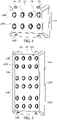
- FIG. 4 illustrates the panel 18.
- the panel 18 includes an array 134 of cleats 22.
- Each cleat 22 is shaped with the same shape of the cleats 22 of the rail 14 such that an object 30 may engage either a rail 14 or a panel 18.
- the array 134 includes multiple rows 138 and multiple columns 142, and the rows 138 and the columns 142 of the panel are evenly spaced.
- the array 134 includes two rows 138 and four columns 142, with a total of eight cleats 22.
- the panel 18 includes fastener slots 82 which permit support fasteners 78 to extend therethrough to engage the wall W.
- the fastener slots 82 are spaced at regular distances along the rows 138 which correspond generally to standard stud spacing dimensions within walls W such that fasteners can be supported on studs of the wall W.
- the panel 18 includes at least one receiver 26 capable of engaging a cleat 22 of a rail 14. As such, the panel 18 may function as either a wall W supported panel 18 or a rail supported panel 54.
- the panel 18 may include fewer or more cleats 22.
- the panel 18 may include six rows and four columns.
- the cleats 22 may be arranged in an array 150 consisting of multiple sub-arrays 154, which may be generally similar to the array 134 of the smaller panel 18.
- each sub-array 154 of the panel of FIG. 5 includes two rows 138 and four columns 142, but fewer or more rows 138 and columns 142 in the sub-array 154, as well as other arrangements of the cleats 22, are possible.
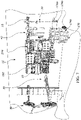
- FIG. 6 illustrates a wall organization system 10 including a panel 18.
- multiple panels 18 are separately secured to the wall W by one or more respective support fastener(s) 78 extending through a respective fastener slot 82.
- the illustrated wall organization system 10 includes multiple types of objects 30 secured to the panels 18.
- One of the objects 30 is a workbench 50.
- Other objects include racks for supporting tools and/or battery packs; shelves; and toolboxes.
- FIG. 7 illustrates another embodiment of a wall organization system 11 including an elongated panel or rail 15 and a panel 18'.
- both the rail 15 and the panel 18' include at least one male mating feature 162 and at least one female mating feature 166, each positioned on the periphery of the rail 15 or panel 18'.
- the rail 15 can engage the panel 18' through respective male and female mating features 162, 166.
- the rails 15 and panels 18' include cleats 22 as described with reference to the rails 14 and panels 18 of the wall organization system 10.
- the cleats 22 are configured to engage many different objects 30.
- the wall organization system 11 may further include a hand truck 170 for transporting tool boxes 174a, 174b, 174c between the wall organization system 11 and a worksite.
- the tool boxes 174a, 174b, 174c may be of different sizes and/or volumes, and may be removably supported on either a rail 15, a panel 18', or the hand truck 170.
- Each tool box 174a, 174b, 174c may further include cleats 22 to engage additional tool boxes 174a, 174b, 174c, or other objects 30.
- FIG. 8 illustrates the rail 15.
- the rail 15 includes cleats 22, at least one male mating feature 162, and at least one female mating feature 166.
- the rail 15 further includes fastener slots 82 through which a fastener 78 can extend to retain the rail 15 on a stud of the wall W.
- the rail 15 can be supported in a generally horizontal configuration as illustrated in FIG. 7 in which the rail 15 is oriented in a direction parallel to the ground G.
- the rail 15 can be supported in a generally vertical configuration in which the rail 15 is oriented in a direction perpendicular relative to the ground G.
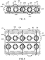
- FIG. 9 illustrates the panel 19.
- the panel 19 includes cleats 22, at least one male mating feature 162, and at least one female mating feature 166.
- the panel 19 includes fastener slots 82 through which a fastener 78 can extend to retain the rail 15 on a stud of the wall W.
- the panel 19 includes an array 134 of cleats 22.
- the panel 19 may include multiple subarrays 154 of cleats 22 similar to the sub-arrays 150 of the panel 18.
- Cleats 22 of a given panel 19 may define half-cleats 22 which are operable to cooperate with adjacent panels 18' or rails 15 to form a full cleat 22 and support an object 30.
- the panel 19 can be supported in a generally vertical configuration in which longer sides of the panel 19 are oriented in a direction perpendicular relative to the ground G.
- FIG. 10 illustrates one of the male mating features 162 of the panel 19 engaging the female mating feature 166 of the rail 15. Further, FIG. 10 illustrates the location of studs S of the wall W.
- the slots 82 of the rail 15 and the panel 19 are aligned in multiple rows and columns. The slots 82 provide multiple locations through which fasteners can support the rail/panel on the studs, and may also assist in positioning the rail/panel in a horizontal or vertical orientation prior to securing the rail/panel to the studs.
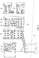
- FIGS. 11 and 11A illustrate a mounting bracket 178.
- the mounting bracket 178 includes at least one bracket hook 180 which engages a portion of multiple cleats 22 of the rail 15 or the panel 19.
- the mounting bracket 178 includes two hooks 180, with one bracket hook 180 engaging a portion of one cleat 22, and the second bracket hook 180 engaging a portion of an adjacent cleat 22.
- a tab 182 of the mounting bracket 178 engages a detent 186 positioned in the rail 15 or the panel 19 between two cleats.
- FIG. 11A illustrates the engagement between the tab 182 and the detent 186.
- the tab 182 is cantilevered relative to a body of the mounting bracket 178.
- the tab 182 locks the location of the mounting bracket 178 relative to the cleats 22.
- the mounting bracket 178 may be fastened to the rail 15 or panel 19.
- a fastener 188 extends through the tab 182 and connects the mounting bracket 178 to the rail 15.
- the fastener 188 may fix the mounting bracket 178 to the wall W or a stud S.
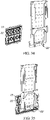
- FIGS. 12-14 illustrate a panel 19 supporting a shelf 190.
- multiple panels 18' engage each other through respective male and female mating features 162, 166, and shelves 190 are supported by either one or multiple panels 18'. That is, one of the shelves 190 can be supported across multiple panels 18'.
- a single shelf 190 is supported on a single panel 19.
- Each shelf 190 can be mounted on either a rail 15 or a panel 19.
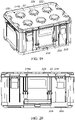
- FIGS. 15 and 16 illustrate a crate 194.
- the crate 194 includes a base panel 198 and a rear surface 202 including hooks 206 which are configured to engage cleats 22 of either a rail 15 or a panel 19.
- the base panel 198 may be configured to engage a top surface 210 of another crate 194 for stacking multiple crates 194.
- the base panel 198 may also be configured to engage the hand truck 170 for transporting between the wall organization system 11 and a worksite.
- the base panel 198 may engage cleats 22 of the tool boxes 174a, 174b, 174c.
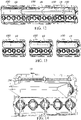
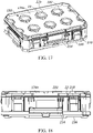
- FIGS. 17-20 illustrate the tool boxes 174a and 174b in detail.
- Each tool box 174a, 174b includes a handle 214, a hinge 218, a top surface 222, and a bottom surface 226.
- Each tool box 174a, 174b includes cleats 22 positioned on the top surface 222 in an array 150 similar to the panel 19.
- the hinge 218 is operable to open and close to permit or restrict access to a void defined by the tool box 174a, 174b.
- the top surface 222 of one tool box 174a is operable to engage a bottom surface 226 of another tool box 174a, 174b, the rail 15, the panel 19, or the hand truck 170.
- the tool box 174c includes each of the features of the tool boxes 174a, 174b.
- the tool boxes 174a, 174b, 174c may be of different sizes to accommodate different objects 30 therein.
- FIGS. 21-31 illustrate various hanging attachments 42 each including at least one mounting bracket 178 and configured to support at least one object 30.
- the mounting bracket 178 includes hooks 180 ( FIG. 11 ) as described above, which engage cleats 22 to support the mounting bracket 178 on a rail 15 or panel 19.
- FIG. 21 illustrates an S-hook 230, a first U-hook 234, and a second U-hook 238.
- the S-hook 230 is rotatably attached to the mounting bracket 178 at a first end 242, with a second end 246 of the S-hook 230 being rotatable away from the rail 15 about the first end 242.
- the first U-hook 234 and the second U-hook 238 each include a pair of elongated supports having upstanding ends.
- the first U-hook 234 and the second U-hook 238 have different sizes and shapes.
- FIGS. 22 and 25 illustrate a first hand tool organizer 250 and a second hand tool organizer 254, respectively.
- Each hand tool organizer 250, 254 functions as a hanging attachment 42 for supporting hand tools on a rail 15 or panel 19 via the mounting bracket 178.
- the organizers 250, 254 are supported by multiple mounting brackets 178.
- FIG. 23 illustrates a wire basket 258.
- FIG. 24 illustrates a bicycle hook 260.
- the bicycle hook 260 is further illustrated in FIG. 7 with a bicycle (i.e., bicycle object 30) mounted thereon.
- FIG. 26 illustrates a third U-hook 262.
- the U-generic hook 262 includes a pair of upstanding ends that are connected together.
- FIG. 27 illustrates a sporting good holder 266.
- the sporting good holder 266 may include a wireframe 270 configured to receive a ball.
- FIG. 28 illustrates a driver holder 274.
- the driver holder 274 is configured to optionally support at least one drill or driver 278, at least one battery 282, and at least one battery charger 286.
- the drill driver holder 274 may also include an auxiliary support structure 290 configured to optionally support other objects 30 such as accessories (e.g., drill bits) and other hand tools (e.g., screwdrivers).
- FIG. 29 illustrates a tool interface 294.
- the tool interface 294 is supported by a mounting bracket 178.
- the tool interface 294 may engage a tool, such as an outdoor power tool 298 as shown in FIG. 29A .
- the tool interface 294 provides support means for engaging a receptacle 302 of an outdoor power tool 298.
- the receptacle 302 may also be configured to receive a battery 282 to power the outdoor power tool 298.
- the outdoor power tool 298 may be, without limitation, a blower (such as the blower 122), a chain saw, a string trimmer (such as the string trimmer 114), or the like.
- FIG. 30 illustrates a battery holder 306 configured to support at least one battery 282.
- FIG. 30 illustrates a battery holder 306 configured to support at least one battery 282.
- the tool holder 310 configured to support a tool.
- the tool holder 310 includes a tool interface 312 operable to engage a receptacle of a tool similar to the tool interface 294.
- the receptacle of the tool may be a battery receptacle of the tool.
- a third hand tool organizer 314 includes a wireframe 318 which directly engages one or more cleat(s) 22 to support the third hand tool organizer 314 on a rail 15 or a panel 19.
- the third hand tool organizer 314 is illustrated in FIGS. 32-33 .
- FIGS. 34-37 illustrate an alternate workbench 50'.
- the alternate workbench 50' is similar to the workbench 50 and, as shown in FIGS. 34-35 , is removably supported on either a rail 15 or a panel 19.
- FIG. 35 illustrates the workbench 50' attached to the panel 19 in a retracted position in which the workbench 50' is parallel to the wall W.
- FIGS. 36-37 illustrate movement of the workbench 50' between the retracted position and an extended position in which the workbench 50' extends perpendicularly from the wall W.
- the workbench 50' has a first hinge 66' between the workbench 50' and the panel 19 and a similar second hinge 70' between a distal end of the workbench 50' and a leg 74'.
- the workbench 50' further includes at least one pivotable support beam 322 extending between the workbench 50' and the leg 74'.
- FIGS. 38-39 illustrate a combination hand truck and workbench assembly 50" that is supported for movement by wheels.
- the hand truck 170 may also support multiple tool boxes 174a.
- the second alternate workbench 50" may also include slots 326 configured to receive clamps 330 or other objects 30.
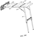
- FIGS. 38A-46 illustrate another alternate workbench 50".
- the alternate workbench 50" is similar to the workbench 50 and the workbench 50'. Features described with respect to the workbench 50 and the workbench 50' may be equally applicable to the alternate workbench 50". Some of the features in the workbench 50 and the workbench 50' are within the workbench 50" and are denoted with the reference numeral and double apostrophes (").
- the movable portion 62" of the workbench 50" includes three top portions 332.
- the top portions 332 are configured to engage clamps 330 or other objects 30.
- Channels 333 are positioned between each of the top portions 332.
- the channels 333 are shaped to define T-shaped slots for engaging clamps 330 or other objects 30.
- the channels 333 may be otherwise shaped.
- the workbench 50" is supportable on the rail 14 of the wall organization system 10 via the hanging attachment 42".
- the hanging attachment 42" includes at least one mounting bracket 178 configured to engage at least a portion of one cleat 22 on the rail 16 to support the workbench 50".
- the workbench 50" further comprises legs 74" similar to the legs 74' of the workbench 50' and a movable portion 62" (i.e., a table portion 62") similar to the movable portion of the workbench 50.
- FIG. 38C illustrates the workbench 50" in a work position in which the movable portion 62" is perpendicular relative to the wall W and supported on the ground G by the legs 74".
- FIG. 38A To move the workbench 50" to an upper storage position illustrated in FIG. 38A , the legs 74" are collapsed, and an upward force is applied to the movable portion 62".
- FIG. 38B illustrates the workbench 50" in an intermediate position between the upper storage position and the work position. In the upper storage position, the work surface of the movable portion 62" which faces away from the ground G in the work position faces towards the wall W in the upper storage position. The opposite process is carried out to move the workbench 50" from the upper storage position to the work position.
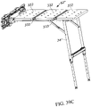
- the workbench 50" is also movable between the work position and a lower storage position.
- the legs 74" are collapsed, and a downward force is applied to the movable portion 62".
- FIG. 39B illustrates the workbench 50" in an intermediate position between the lower storage position and the work position.
- the work surface of the movable portion 62" which faces away from the ground G in the work position faces away from the wall W in the lower storage position. The opposite process is carried out to move the workbench 50" from the lower storage position to the work position.
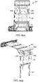
- FIGS. 40-42 illustrate a pin 334 engaging the hanging attachment 42", the pin 334 being configured to retain the movable portion 62" in one of the upper storage position ( FIG. 42 ), the lower storage position (not shown), or the work position ( FIGS. 40, 41 ).
- the first hinge 66" engages the movable portion 62" at a position centrally located relative to holes 338 of the hanging attachment 42".
- the holes 338 are configured as a rectangular array around the first hinge 66" when the hinge 66" is applied to the hanging attachment 42".
- the pin 334 inhibits excess upward motion of the movable portion 62" when the legs 74" support the movable portion 62" on the ground G.
- the pin 334 inhibits lateral motion of the movable portion 62" away from the wall W when stored in the upper storage position.
- the pin 334 may also engage a hole 338 to inhibit lateral motion of the movable portion 62" away from the wall W when stored in the lower storage position (not shown).
- FIG. 43 illustrates the legs 74" of the workbench 50" in detail.
- the legs 74" include telescopic portions 342 having holes 346 therein.
- the legs 74" further include fixed portion 348.
- the holes 346 correspond with various discrete heights of the movable portion 62" (i.e., the table) relative to the ground G. This provides a course adjustment of the height of the movable portion 62" relative to the ground G.
- a pin 350 secures the telescopic portion 342 to the fixed portion 348 to fix the telescopic portion 342 relative to the fixed portion 348.
- the ends of the legs 74", and more specifically, the telescopic portions 342 terminate with feet 354.
- the feet 354 are received by the telescopic portion 342 such that they are pivotably adjustable to provide a fine adjustment of the height of the movable portion 62" relative to the ground G.
- FIG. 44 illustrates a bottom perspective view of one embodiment of the alternate workbench 50".
- the alternate workbench 50" includes spring dampers 356 between the hanging attachment 42" and the movable portion 62".
- the spring dampers 356 are configured to assist the user in folding out the movable portion 62" (i.e., moving from the upper storage position of FIG. 38A to the work position of FIGS. 38C and 39C ).
- FIGS. 45A and 45B illustrate perspective views of another embodiment of a workbench 50".
- the workbench 50" includes a storage support interface 358 coupled to the legs 74".
- the storage support interface 358 includes features (e.g., cleats 22) that function similar to the features on the rails 14 to engage correspondingly sized objects 30.
- the storage support interface 358 is visible when the workbench 50" is in either the upper storage position or the use position.
- FIGS. 46A and 46B illustrate perspective views of another embodiment of the alternate workbench 50".
- the alternate workbench 50" includes a crossbar 362 extending between each of the legs 74".
- the crossbar 362 may be used to hang clamps 366 or another object 30 therefrom.
- this embodiment of the alternate workbench 50" may optionally include an additional dedicated storage interface 370.
- the additional dedicated storage interface 370 may connect another object 30 (such as, without limitation, an extra table surface portion such as a router table) to the legs 74".
- crossbar 362 and the storage interface 370 are visible when the workbench 50" is in either the upper storage position or the use position.
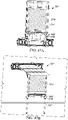
- FIGS. 47A and 47B illustrate perspective views of another embodiment of workbench 50".
- the workbench 50" includes a marking board 374 mounted to the legs 74".
- the marking board 374 may be, without limitation, a dry erase white board.
- the alternate workbench 50" may further include a storage container 378 operable to hold objects 30.
- the objects 30 held within the storage container 378 may be, without limitation, markers and erasers.
- the container 378 is mounted on the fixed portion 348 ( FIGS. 47A, 47B ) of the legs 74". However, the container 378 may be otherwise mounted on the legs 74". As illustrated in FIGS. 47A and 47B , the marking board 374 and the container 378 are visible when the workbench 50" is in either the upper storage position or the use position.
- FIGS. 48A and 48B illustrate perspective views of another embodiment of workbench 50".
- the workbench 50" includes a soft tool storage attachment 382 configured to store objects 30 such as, for example, hand tools thereon.
- the soft tool storage attachment 382 may include pouches 386 and MOLLE (i.e., Modular Lightweight Load-carrying Equipment) loops 390 to storage various size objects 30 thereon.
- the soft tool storage attachment 382 may be secured to the legs 74" utilizing straps 394.
- the straps 394 may surround the legs 74", and optionally include hook and loop type fasteners for enhancing ease of assembly and disassembly of the soft tool storage attachment 382 from the legs 74".
- the soft tool storage attachment 382 is visible when the workbench 50" is in either the upper storage position or the use position.
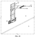
- FIG. 49 illustrates the alternate workbench 50" with the legs 74" in an extended position perpendicular to the wall W and parallel to the ground G. In this position, the legs 74" can function as hooks for supporting objects 30 thereon.
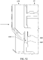
- FIGS. 50-53 illustrate another mounting bracket 178.
- the mounting bracket 178 includes hooks 180.
- the hooks 180 are cantilevered portions which are dimensioned such that one bracket hook 180 engages a portion of one cleat 22, and the second bracket hook 180 engages a portion of an adjacent cleat 22.
- the mounting bracket 178 further includes a retaining member 400.
- the illustrated mounting bracket 178 includes two retaining members 400.
- the illustrated retaining members 400 project vertically and longitudinally with regards to the remainder of the mounting bracket 178.
- the retaining members 400 are dimensioned such that the retaining member 400 can engage the rail 14. As shown in FIG.
- the retaining member 400 is passed laterally through a retention hole 404 (i.e., a retention feature) of the rail 14.
- a retention hole 404 i.e., a retention feature
- the retaining member 400 is translated to a lateral position through the retention hole 404 such that the retaining member 400 is vertically aligned with a retaining tab 408 of the rail 14.
- the mounting bracket 178 is then capable of translation vertically downward through the hole 404 such that the retaining member 400 engages the retaining tab 408 to secure the mounting bracket 178 to the rail 14.
- the hooks 180 also engage the cleats 22 when the retaining member 400 engages the retaining tab 408 such that the hooks 180, cleats 22, retaining member 400 and retaining tab 408 prevent vertical tilt of the mounting bracket 178 relative to the rail 14.
- the hooks 180, cleats 22, retaining member 400 and retaining tab 408 prevent the mounting bracket 178 from rotation relative to the rail 14.
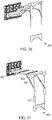
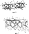
- FIGS. 54 and 55 illustrate another rail 16 with multiple cleats 22.
- the cleats 22 of the rail 16 include a bluff 22a which is integrally formed with the rail 16.
- the bluff 22a connects the outstanding portion 22b of the cleat 22 to the rail 16.
- the outstanding portion 22b is raised form the remainder of the rail 16.
- the outstanding portion 22b can be engaged by either the object 30 directly (e.g., as in the tool holder 310 of FIGS. 32-33 ) or by the mounting bracket 178, with the mounting bracket 178 holding, for example and without limitation, the S-hook 230, the first U-hook 234, or the second U-hook 238 as illustrated in FIG. 21 .
- the S-hook 230, the first U-hook 234, and/or the second U-hook 238 can then support an object 30 thereon.
- bluffs 22a are provided adjacent each outstanding portion 22b on opposite lateral sides of the outstanding portion 22b on a single vertical side of each cleat 22.
- bluffs 22a connect the lower portion of the cleat 22 to the rail 16.
- Adjacent the upper portion of the cleat 22, through slots 22c are provided in the rail 16.
- the through slots 22c extend diagonally between the lower portion of the rail 16 and the upper portion of the rail 16 and generally correspond with the shape outstanding portion 22b of the cleat 22.
- the 54 and 55 may include bluffs 22a adjacent the lower portion of the rail 16 and slots 22c adjacent the upper portion of the rail 16.
- the bluffs 22a thereby form a continuous planar surface that is coextensive with the lower edges of the cleat 22.
- the rail 14, 15, 16 may be provided with a combination of bluffs 22a and through slots 22c around the periphery of the outstanding portion 22b.
- the objects 30 that engage the system 10 may be mounted to an object support which engages a bracket 178.
- the object support may be, without limitation, the previously described shelves 34, storage boxes 38, hanging attachments, tool holders 46, workbenches 50, and the like.
- the object support may be, without limitation, the previously described shelves 190, crate 194, tool boxes 174a, 174b, S-hook 230, first U-hook 234, second U-hook 238, first hand tool organizer 250, second hand tool organizer 254, wire basket 258, bicycle hook 260, third U-hook 262, sporting good holder 266, driver holder 274, tool interface 294, battery holder 306, tool holder 310.
- Other such object supports may be provided on the system 10 to support an object 30 or multiple objects 30 on the wall W.
- the objects 30 to engage the system 10 are not limited to the objects 30 described herein.
- the objects may also include, but are not limited to the following: lights, a fold down seat, a fold out seat, a step stool, a stool, batteries, holders, extension plugs, cord routing mechanisms, dust collection channels, tool bit storage, trash cans, wireform trash bag holders, fans, heaters, drop cloths, storage for rolling craft paper, a paper towel holder, magnetic holding strips, peg boards, dolly mounting structures, storage bins, parf fixture mechanisms, vice storage mechanisms, bike mounting mechanisms, and drying racks.
- lights a fold down seat, a fold out seat, a step stool, a stool, batteries, holders, extension plugs, cord routing mechanisms, dust collection channels, tool bit storage, trash cans, wireform trash bag holders, fans, heaters, drop cloths, storage for rolling craft paper, a paper towel holder, magnetic holding strips, peg boards, dolly mounting structures, storage bins, parf fixture mechanisms, vice storage mechanisms, bike mounting mechanisms, and drying rack
Abstract
A storage support configured to support an object on a support surface. The storage support includes a mount and a plurality of cleats. The mount includes an upper edge and a lower edge. Each of the plurality of cleats includes a first upper cleat edge and a second upper cleat edge that is non-parallel relative to the first upper cleat edge. The first upper cleat edge is oriented non-parallel relative to the upper edge of the mount. Each of the first upper cleat edge and the second upper cleat edge are configured to support the object.
Description
- This application claims priority to co-pending
U.S. Provisional Patent Application No. 63/178,929, filed April 23, 2021 U.S. Provisional Patent Application No. 63/164,145, filed March 22, 2021 U.S. Provisional Patent Application No. 63/071,920, filed August 28, 2020 U.S. Provisional Patent Application No. 63/062,865, filed August 7, 2020 - The present disclosure relates to storage systems, and more particular to modular wall mounted storage systems for tools and the like.
- Hand tools, power tools, and associated accessories such as batteries, tool bits, fasteners, and the like, may be moved frequently between a storage space and a work space. One aspect of accessibility is a user's ability to quickly store an object and remove the object from storage. Another aspect of accessibility is the storage system's ability to engage many objects with a standardized connection mechanism between the system and the object. This may also permit an object to engage the storage system at a plurality of locations. Storage systems may also be accessible for extension or expansion. Finally, storage systems are accessible when located adjacent a work space.
- In one independent aspect, a storage support configured to support an object on a support surface, the storage support comprising a mount including an upper edge and a lower edge, and a plurality of cleats. Each of the cleats project from the surface. Each of the cleats include a first upper cleat edge and a second upper cleat edge that is non-parallel relative to the first upper cleat edge. The first upper cleat edge is oriented non-parallel relative to the upper edge of the mount. Each of the first upper cleat edge and the second upper cleat edge are configured to support the objects.
- In another independent aspect, a modular storage system is configured to support an object on a support surface. The modular support system comprises a mount, a bracket, and a retaining member. The mount includes a surface, a plurality of cleats projecting from the surface, and a retention feature. The bracket is used for removably supporting the object. The bracket includes a bracket hook configured to engage a portion of at least one of the cleats to secure the bracket to the mount. The retaining member is configured to engage the retention feature to inhibit disengagement of the bracket hook from the cleat.
- In another independent aspect, a modular storage system is configured to support an object on a support surface. The modular support system comprises a mount, a bracket, and a workbench. The mount includes a plurality of cleats, each of the plurality of cleats including an outstanding portion projecting from the mount. The bracket is secured to a mounting attachment. The bracket is configured to engage the outstanding portion of the cleat to secure the bracket to the mount. The workbench is pivotally coupled to the mounting attachment for movement between a stored position, in which the workbench is generally parallel with the support surface, and a deployed position, in which the workbench is generally perpendicular with the support surface.
- Other aspects of the disclosure will become apparent by consideration of the detailed description and accompanying drawings.
-
-
FIG. 1 is a perspective view of a multi-level wall organization system including a rail and a panel. -
FIG. 2 is a perspective view of the rail ofFIG. 1 . -
FIG. 3 is a perspective view of a wall organization system including a rail. -
FIG. 4 is a perspective view of a panel ofFIG. 1 . -
FIG. 5 is a perspective view of a panel having a different dimension than the panel ofFIG. 4 . -
FIG. 6 is a perspective view of a wall organization system including a panel. -
FIG. 7 is a perspective view of a different embodiment of a wall organization system including a rail and a panel. -
FIG. 8 is a perspective view of the rail ofFIG. 7 . -
FIG. 9 is a perspective view of the panel ofFIG. 7 . -
FIG. 10 is a front view of the rail and the panel ofFIG. 7 shown as secured to each other and to studs of a wall. -
FIG. 11 is a perspective view of a mounting bracket of the wall organization system ofFIG. 7 . -
FIG. 11A is a cross-sectional view of the mounting bracket ofFIG. 11 taken alongsection line 11A-11A inFIG. 11 . -
FIG. 12 is a perspective view of multiple panels ofFIG. 9 shown engaged with each other and supporting multiple shelves. -
FIG. 13 is a perspective view of multiple panels ofFIG. 9 shown separated from each other and each supporting a shelf. -
FIG. 14 is a perspective view of a single panel ofFIG. 9 shown supporting a shelf. -
FIG. 15 is a front perspective view of a crate for use with a wall organization system. -
FIG. 16 is a rear perspective view of the crate inFIG. 15 . -
FIG. 17 is a perspective view of a first tool box for use with a wall organization system. -
FIG. 18 is a front view of the first tool box ofFIG. 17 . -
FIG. 19 is a perspective view of a second tool box for use with a wall organization system. -
FIG. 20 is a front view of the second tool box ofFIG. 19 . -
FIG. 21 is a perspective view of an S-hook, a first generic hook, and a second generic hook each supported to a rail via a mounting bracket. -
FIG. 22 is a perspective view of a first hand tool organizer supported on a rail via a mounting bracket -
FIG. 23 is a perspective view of a wire basket supported on a rail via a mounting bracket. -
FIG. 24 is a perspective view of a bicycle hook supported on a rail supported via a mounting bracket. -
FIG. 25 is a perspective view of a second hand tool organizer supported on a rail a mounting bracket. -
FIG. 26 is a perspective view of a third generic hook supported on a rail via a mounting bracket. -
FIG. 27 is a perspective view of a sporting good holder supported on a rail via a mounting bracket. -
FIG. 28 is a perspective view of a drill driver holder supported on a panel via a mounting bracket. -
FIG. 29 is a perspective view of an outdoor power tool holder supported on a rail via a mounting bracket. -
FIG. 29A is a rear perspective view of an outdoor power tool known in the prior art. -
FIG. 30 is a perspective view of a battery holder supported on a panel via a mounting bracket. -
FIG. 31 is a perspective view of a power tool holder supported on a panel via a mounting bracket. -
FIG. 32 is a perspective view of a third hand tool organizer supported on a rail via a cleat. -
FIG. 33 is a perspective view of the third hand tool organizer ofFIG. 32 . -
FIG. 34 is a perspective view of a workbench separated from a panel. -
FIG. 35 is a perspective view of the workbench ofFIG. 34 attached to the panel and in a retracted position. -
FIG. 36 is a perspective view of the workbench ofFIG. 34 attached to the panel and in a partially extended position. -
FIG. 37 is a perspective view of the workbench ofFIG. 34 attached to the panel and in an extended position. -
FIG. 38A is a perspective view of an alternate workbench in an upper storage position. -
FIG. 38B is a perspective view of the alternate workbench ofFIG. 38A in an intermediate position between the upper storage position and a work position. -
FIG. 38C is a perspective view of the alternate workbench ofFIG. 38A in a work position. -
FIG. 39A is a perspective view of the alternate workbench ofFIG. 38A in a lower storage position. -
FIG. 39B is a perspective view of the alternate workbench ofFIG. 38A in an intermediate position between the lower storage position and the work position. -
FIG. 39C is a perspective view of the alternate workbench ofFIG. 38A in a work position. -
FIG. 40 is a side view of the alternate workbench ofFIG. 38A with a pin inhibiting excess downward motion of the workbench. -
FIG. 41 is a side view of the alternate workbench ofFIG. 38A with a pin inhibiting excess upward motion of the workbench. -
FIG. 42 is a side view of the alternate workbench ofFIG. 38A with a pin inhibiting motion of the workbench away from the wall. -
FIG. 43 is a perspective view of the alternate workbench ofFIG. 38A illustrating the adjustability of the legs thereof. -
FIG. 44 is a bottom perspective view of the alternate workbench in an intermediate position as inFIG. 38B . -
FIG. 45A is a perspective view of the alternate workbench ofFIG. 38A including a storage support surface coupled to the legs. -
FIG. 45B is a perspective view of the alternate workbench ofFIG. 38C including a storage support surface coupled to the legs. -
FIG. 46A is a perspective view of the alternate workbench ofFIG. 38A including a crossbar and an additional storage interface. -
FIG. 46B is a perspective view of the alternate workbench ofFIG. 38C including a crossbar and an additional storage interface. -
FIG. 47A is a perspective view of the alternate workbench ofFIG. 38A including a marking board coupled to the legs. -
FIG. 47B is a perspective view of the alternate workbench ofFIG. 38C including a marking board coupled to the legs. -
FIG. 48A is a perspective view of the alternate workbench ofFIG. 38A including a soft tool storage attachment coupled to the legs. -
FIG. 48B is a perspective view of the alternate workbench ofFIG. 38C including a soft tool storage attachment coupled to the legs. -
FIG. 49 is a perspective view of the alternate workbench ofFIG. 38A with the legs in an extended position. -
FIG. 50 is a front view of a mounting bracket. -
FIG. 51 is a side view of the mounting bracket ofFIG. 50 . -
FIG. 52 is a side view of the mounting bracket ofFIG. 50 in lateral position to engage the rail ofFIG. 18 . -
FIG. 53 is a side view of the mounting bracket ofFIG. 50 engaging the rail ofFIG. 18 . -
FIG. 54 is a perspective view of another rail. -
FIG. 55 is a perspective view of the S-hook, the first generic hook, and the second generic hook each supported on the rail ofFIG. 54 via the mounting bracket. - Before any aspects are explained in detail, it is to be understood that the disclosure is not limited in its application to the details of construction and the arrangement of components set forth in the following description or illustrated in the following drawings. The disclosure is capable of other embodiments and of being practiced or of being carried out in various ways. Also, it is to be understood that the phraseology and terminology used herein is for the purpose of description and should not be regarded as limiting. The use of "including," "comprising" or "having" and variations thereof herein is meant to encompass the items listed thereafter and equivalents thereof as well as additional items. The terms "mounted," "connected" and "coupled" are used broadly and encompass both direct and indirect mounting, connecting and coupling. Further, "connected" and "coupled" are not restricted to physical or mechanical connections or couplings, whether direct or indirect.
-
FIG. 1 illustrates a multi-levelwall organization system 10 including one ormore rails 14 and/orpanel 18. In the illustratedsystem 10,multiple rails 14 are supported on a support surface or wall W. Similarly, in the illustratedsystem 10,multiple panels 18 are supported on the wall W. Eachrail 14 andpanel 18 includes at least onecleat 22. In the illustrated embodiment, thecleat 22 is a diamond-shapedcleat 22. In other embodiments, thecleat 22 may have another shape (e.g., hexagonal, octagonal). - The
cleat 22 is configured to engage and support many types ofobjects 30 including, but not limited to, shelves 34,storage boxes 38, hangingattachments 42,tool holders 46,workbenches 50, tools, and the like. Eachobject 30 includes anopening 26 having a shape that corresponds to and receives thecleat 22. The engagement between thecleat 22 and theobject 30 may be a locking engagement, or a gravitational engagement similar to a French cleat. As such, theobjects 30 can be attached to the support surface (e.g., a wall W) through either therail 14 or thepanel 18. Therail 14 and thepanel 18 each include at least onecleat 22 which may support anobject 30 on the wall W. Thestorage boxes 38 can be stackable containers and may include an engagement interface and/or locking mechanism for securing thebox 38 to therail 14 orpanel 18. Some examples of such engagement interfaces and locking mechanisms are described inU.S. Patent Application No. 63/030,694, filed on May 27, 2020 - In the illustrated embodiment, rail-supported
panels 54 are supported with respect to the wall W via therails 14. Such rail-supportedpanels 54 include thereceiver 26 dimensioned to engage thecleat 22 of therail 14. The rail-supportedpanels 54 further includecleats 22 configured to support theobjects 30. Thus, eachobject 30 can be supported with respect to the wall W by either therail 14 or by the rail-supportedpanel 54. As will be discussed with respect toFIG. 2 , therails 14 are modular in nature, and can be mounted on the wall W at a desired height with respect to a secondary support surface or ground G. -
FIG. 1 illustrates aworkbench 50 fastened to the wall W through a rail-supportedpanel 54 and arail 14. In other embodiments, theworkbench 50 may be fastened to the wall W by apanel 18 alone. Theworkbench 50 includes a fixedportion 58 and amovable portion 62. The fixedportion 58 engages one of therail 14, thepanel 18, or the rail-supportedpanel 54 and is secured relative to the wall W. In the illustrated embodiment, the fixedportion 58 of theworkbench 50 engages the rail-supportedpanel 54. Other configurations are possible, such as theworkbench 50 being removable from therail 14, thepanel 18, or the rail-supportedpanel 54. Themovable portion 62 is connected to the fixedportion 58 by afirst hinge 66. Themovable portion 62 is movable relative to the fixedportion 58 between a storage position in which themovable portion 62 of theworkbench 50 is oriented generally parallel to the wall W and an extended position (shown inFIG. 1 ) in which themovable portion 62 of theworkbench 50 is oriented at an oblique angle (e.g., perpendicular) relative to the support surface W. In the extended position, themovable portion 62 functions as a work surface or work space of theworkbench 50. In some embodiments, theworkbench 50 may include a work surface formed by a plurality of modular table sections that can be removably coupled (e.g., by fasteners) to a frame, depending on a type of operation to be performed. - In the illustrated embodiment, a
leg 74 is connected (e.g., by a second hinge 70) to a distal end of themovable portion 62 relative to thefirst hinge 66. Theleg 74 may be moved between an extended position in which theleg 74 engages the ground G and a storage position in which theleg 74 extends generally parallel to themovable portion 62. When theleg 74 engages the ground G with the table in the extended position, theleg 74 further supports theworkbench 50. -
FIG. 2 illustrates arail 14 includingcleats 22. Thewall organization system 10 includes asupport fastener 78 which engages the wall W to support therail 14 relative to the wall W and to transmit loads exerted on therail 14 to the wall W. Thesupport fastener 78 engages afastener slot 82 of therail 14. Therail 14 may includemultiple fastener slots 82 at regular distances along alongitudinal axis 86 extending between afirst end 90 of therail 14 and asecond end 94 of therail 14. The distance between thefastener slots 82 corresponds generally to standard stud spacing dimensions within walls W such that fasteners can engage studs of the wall W. - In the illustrated embodiment (
FIG. 2 ), therail 14 includes a plurality ofcleats 22 which may be arranged at regular distances along thelongitudinal axis 86 of therail 14. Therail 14 has arail extension receiver 98 at both thefirst end 90 and thesecond end 94. Thecleats 22 closest to thefirst end 90 and thesecond end 94 of therail 14 are positioned along thelongitudinal axis 86 such that the gap between thecleat 22 closest to thefirst end 90 and thefirst end 90 is equal in length to the gap between thecleat 22 closest to thesecond end 94 and thesecond end 94. As a result, spacing betweencleats 22 of therail 14 and anadjacent rail 14 may be regular (i.e., uniform). Thelongitudinal axis 86 of therail 14 intersects therail extension receiver 98. Arail extension 102 may engage arail segment 106 and anadjacent rail segment 110 to extend therail 14 along thelongitudinal axis 86. As such, additionaladjacent rails 14 may be attached to an existingsegment rail 14 to extend the length of arail 14 along thelongitudinal axis 86. -
FIG. 3 illustrates awall organization system 10 including arail 14. Therail 14 includesmultiple rail segments rail extensions 102. Eachrail segment 106 may be separately secured to the wall W by arespective support fastener 78. The illustratedwall organization system 10 supportsmultiple objects 30. Theobjects 30 illustrated inFIG. 3 include astring trimmer 114, ashovel 118, ablower 122, ahedge trimmer 126, anedger 130, and theworkbench 50.Other objects 30 are capable of being supported on therail 14. As previously discussed, the hangingattachment 42 may engage thecleat 22.Various hanging attachments 42 can serve as an intermediate between any givenobject 30 and therail 14. The hangingattachments 42 may include but are not limited to fixed "U", "T", "J" or otherwise shaped brackets, hinges, or other fixed or movable components to enhance a user's ability to quickly support or remove theobject 30 from therail 14. -
FIG. 4 illustrates thepanel 18. Thepanel 18 includes anarray 134 ofcleats 22. Eachcleat 22 is shaped with the same shape of thecleats 22 of therail 14 such that anobject 30 may engage either arail 14 or apanel 18. In the illustrated embodiment, thearray 134 includesmultiple rows 138 andmultiple columns 142, and therows 138 and thecolumns 142 of the panel are evenly spaced. In the illustrated embodiment, thearray 134 includes tworows 138 and fourcolumns 142, with a total of eightcleats 22. Thepanel 18 includesfastener slots 82 which permitsupport fasteners 78 to extend therethrough to engage the wall W. Thefastener slots 82 are spaced at regular distances along therows 138 which correspond generally to standard stud spacing dimensions within walls W such that fasteners can be supported on studs of the wall W. Thepanel 18 includes at least onereceiver 26 capable of engaging acleat 22 of arail 14. As such, thepanel 18 may function as either a wall W supportedpanel 18 or a rail supportedpanel 54. - In other embodiments, the
panel 18 may include fewer or more cleats 22. For example, as shown inFIG. 5 thepanel 18 may include six rows and four columns. In some embodiments, thecleats 22 may be arranged in anarray 150 consisting ofmultiple sub-arrays 154, which may be generally similar to thearray 134 of thesmaller panel 18. For example, each sub-array 154 of the panel ofFIG. 5 includes tworows 138 and fourcolumns 142, but fewer ormore rows 138 andcolumns 142 in the sub-array 154, as well as other arrangements of thecleats 22, are possible. -
FIG. 6 illustrates awall organization system 10 including apanel 18. In the illustrated embodiment,multiple panels 18 are separately secured to the wall W by one or more respective support fastener(s) 78 extending through arespective fastener slot 82. The illustratedwall organization system 10 includes multiple types ofobjects 30 secured to thepanels 18. One of theobjects 30 is aworkbench 50. Other objects include racks for supporting tools and/or battery packs; shelves; and toolboxes. -
FIG. 7 illustrates another embodiment of awall organization system 11 including an elongated panel orrail 15 and a panel 18'. In thewall organization system 11, both therail 15 and the panel 18' include at least onemale mating feature 162 and at least onefemale mating feature 166, each positioned on the periphery of therail 15 or panel 18'. As such, in thewall organization system 11, therail 15 can engage the panel 18' through respective male and female mating features 162, 166. Therails 15 and panels 18' includecleats 22 as described with reference to therails 14 andpanels 18 of thewall organization system 10. Thecleats 22 are configured to engage manydifferent objects 30. - The
wall organization system 11 may further include ahand truck 170 for transportingtool boxes wall organization system 11 and a worksite. Thetool boxes rail 15, a panel 18', or thehand truck 170. Eachtool box cleats 22 to engageadditional tool boxes other objects 30. -
FIG. 8 illustrates therail 15. Therail 15 includescleats 22, at least onemale mating feature 162, and at least onefemale mating feature 166. Therail 15 further includesfastener slots 82 through which afastener 78 can extend to retain therail 15 on a stud of the wall W. Therail 15 can be supported in a generally horizontal configuration as illustrated inFIG. 7 in which therail 15 is oriented in a direction parallel to the ground G. Alternatively, therail 15 can be supported in a generally vertical configuration in which therail 15 is oriented in a direction perpendicular relative to the ground G. -
FIG. 9 illustrates thepanel 19. Thepanel 19 includescleats 22, at least onemale mating feature 162, and at least onefemale mating feature 166. Thepanel 19 includesfastener slots 82 through which afastener 78 can extend to retain therail 15 on a stud of the wall W. Thepanel 19 includes anarray 134 ofcleats 22. Thepanel 19 may includemultiple subarrays 154 ofcleats 22 similar to thesub-arrays 150 of thepanel 18.Cleats 22 of a givenpanel 19 may define half-cleats 22 which are operable to cooperate with adjacent panels 18' or rails 15 to form afull cleat 22 and support anobject 30. The panels 18' illustrated inFIG. 7 are supported in a generally horizontal configuration in which longer sides of thepanel 19 are oriented in a direction parallel to the ground G. Alternatively, thepanel 19 can be supported in a generally vertical configuration in which longer sides of thepanel 19 are oriented in a direction perpendicular relative to the ground G. -
FIG. 10 illustrates one of the male mating features 162 of thepanel 19 engaging thefemale mating feature 166 of therail 15. Further,FIG. 10 illustrates the location of studs S of the wall W. In the illustrated embodiment, theslots 82 of therail 15 and thepanel 19 are aligned in multiple rows and columns. Theslots 82 provide multiple locations through which fasteners can support the rail/panel on the studs, and may also assist in positioning the rail/panel in a horizontal or vertical orientation prior to securing the rail/panel to the studs. -
FIGS. 11 and 11A illustrate a mountingbracket 178. InFIG. 11 , the mountingbracket 178 includes at least onebracket hook 180 which engages a portion ofmultiple cleats 22 of therail 15 or thepanel 19. In the illustrated embodiment, the mountingbracket 178 includes twohooks 180, with onebracket hook 180 engaging a portion of onecleat 22, and thesecond bracket hook 180 engaging a portion of anadjacent cleat 22. Atab 182 of the mountingbracket 178 engages adetent 186 positioned in therail 15 or thepanel 19 between two cleats.FIG. 11A illustrates the engagement between thetab 182 and thedetent 186. Thetab 182 is cantilevered relative to a body of the mountingbracket 178. As such, thetab 182 locks the location of the mountingbracket 178 relative to thecleats 22. Optionally, as shown inFIG. 11 , the mountingbracket 178 may be fastened to therail 15 orpanel 19. In the illustrated embodiment, afastener 188 extends through thetab 182 and connects the mountingbracket 178 to therail 15. In some embodiments, thefastener 188 may fix the mountingbracket 178 to the wall W or a stud S. -
FIGS. 12-14 illustrate apanel 19 supporting ashelf 190. InFIG. 12 , multiple panels 18' engage each other through respective male and female mating features 162, 166, andshelves 190 are supported by either one or multiple panels 18'. That is, one of theshelves 190 can be supported across multiple panels 18'. InFIGS. 13 and 14 , asingle shelf 190 is supported on asingle panel 19. Eachshelf 190 can be mounted on either arail 15 or apanel 19. -
FIGS. 15 and 16 illustrate acrate 194. Thecrate 194 includes abase panel 198 and arear surface 202 includinghooks 206 which are configured to engagecleats 22 of either arail 15 or apanel 19. Thebase panel 198 may be configured to engage atop surface 210 of anothercrate 194 for stackingmultiple crates 194. Thebase panel 198 may also be configured to engage thehand truck 170 for transporting between thewall organization system 11 and a worksite. Thebase panel 198 may engagecleats 22 of thetool boxes -
FIGS. 17-20 illustrate thetool boxes tool box handle 214, ahinge 218, atop surface 222, and abottom surface 226. Eachtool box cleats 22 positioned on thetop surface 222 in anarray 150 similar to thepanel 19. Thehinge 218 is operable to open and close to permit or restrict access to a void defined by thetool box top surface 222 of onetool box 174a is operable to engage abottom surface 226 of anothertool box rail 15, thepanel 19, or thehand truck 170.FIG. 7 illustrates thetool boxes tool box 174c. Thetool box 174c includes each of the features of thetool boxes tool boxes different objects 30 therein. -
FIGS. 21-31 illustrate various hangingattachments 42 each including at least one mountingbracket 178 and configured to support at least oneobject 30. The mountingbracket 178 includes hooks 180 (FIG. 11 ) as described above, which engagecleats 22 to support the mountingbracket 178 on arail 15 orpanel 19.FIG. 21 illustrates an S-hook 230, afirst U-hook 234, and asecond U-hook 238. The S-hook 230 is rotatably attached to the mountingbracket 178 at afirst end 242, with asecond end 246 of the S-hook 230 being rotatable away from therail 15 about thefirst end 242. In the illustrated embodiment, thefirst U-hook 234 and thesecond U-hook 238 each include a pair of elongated supports having upstanding ends. Thefirst U-hook 234 and the second U-hook 238 have different sizes and shapes. - The mounting
brackets 178 can support various other hangingattachments 42.FIGS. 22 and25 illustrate a firsthand tool organizer 250 and a secondhand tool organizer 254, respectively. Eachhand tool organizer attachment 42 for supporting hand tools on arail 15 orpanel 19 via the mountingbracket 178. In the illustrated embodiment, theorganizers brackets 178. -
FIG. 23 illustrates awire basket 258.FIG. 24 illustrates abicycle hook 260. Thebicycle hook 260 is further illustrated inFIG. 7 with a bicycle (i.e., bicycle object 30) mounted thereon.FIG. 26 illustrates athird U-hook 262. In the illustrated embodiment, theU-generic hook 262 includes a pair of upstanding ends that are connected together.FIG. 27 illustrates a sportinggood holder 266. The sportinggood holder 266 may include awireframe 270 configured to receive a ball. -
FIG. 28 illustrates adriver holder 274. Thedriver holder 274 is configured to optionally support at least one drill ordriver 278, at least onebattery 282, and at least onebattery charger 286. Thedrill driver holder 274 may also include anauxiliary support structure 290 configured to optionally supportother objects 30 such as accessories (e.g., drill bits) and other hand tools (e.g., screwdrivers). -
FIG. 29 illustrates atool interface 294. Thetool interface 294 is supported by a mountingbracket 178. Thetool interface 294 may engage a tool, such as anoutdoor power tool 298 as shown inFIG. 29A . In the illustrated embodiment, thetool interface 294 provides support means for engaging areceptacle 302 of anoutdoor power tool 298. In the illustrated embodiment, thereceptacle 302 may also be configured to receive abattery 282 to power theoutdoor power tool 298. Theoutdoor power tool 298 may be, without limitation, a blower (such as the blower 122), a chain saw, a string trimmer (such as the string trimmer 114), or the like.FIG. 30 illustrates abattery holder 306 configured to support at least onebattery 282.FIG. 31 illustrates atool holder 310 configured to support a tool. In the illustrated embodiment, thetool holder 310 includes atool interface 312 operable to engage a receptacle of a tool similar to thetool interface 294. In some embodiments, the receptacle of the tool may be a battery receptacle of the tool. - Other hanging
attachments 42 are available which do not include a mountingbracket 178. For example, a thirdhand tool organizer 314 includes awireframe 318 which directly engages one or more cleat(s) 22 to support the thirdhand tool organizer 314 on arail 15 or apanel 19. The thirdhand tool organizer 314 is illustrated inFIGS. 32-33 . -
FIGS. 34-37 illustrate an alternate workbench 50'. The alternate workbench 50' is similar to theworkbench 50 and, as shown inFIGS. 34-35 , is removably supported on either arail 15 or apanel 19.FIG. 35 illustrates the workbench 50' attached to thepanel 19 in a retracted position in which the workbench 50' is parallel to the wall W.FIGS. 36-37 illustrate movement of the workbench 50' between the retracted position and an extended position in which the workbench 50' extends perpendicularly from the wall W. The workbench 50' has a first hinge 66' between the workbench 50' and thepanel 19 and a similar second hinge 70' between a distal end of the workbench 50' and aleg 74'. The workbench 50' further includes at least onepivotable support beam 322 extending between the workbench 50' and theleg 74'. -
FIGS. 38-39 illustrate a combination hand truck andworkbench assembly 50" that is supported for movement by wheels. As shown inFIGS. 38-39 , thehand truck 170 may also supportmultiple tool boxes 174a. The secondalternate workbench 50" may also include slots 326 configured to receive clamps 330 orother objects 30. -
FIGS. 38A-46 illustrate anotheralternate workbench 50". Thealternate workbench 50" is similar to theworkbench 50 and the workbench 50'. Features described with respect to theworkbench 50 and the workbench 50' may be equally applicable to thealternate workbench 50". Some of the features in theworkbench 50 and the workbench 50' are within theworkbench 50" and are denoted with the reference numeral and double apostrophes ("). - As illustrated in at least
FIG. 38C , themovable portion 62" of theworkbench 50" includes threetop portions 332. Thetop portions 332 are configured to engage clamps 330 orother objects 30.Channels 333 are positioned between each of thetop portions 332. Thechannels 333 are shaped to define T-shaped slots for engaging clamps 330 orother objects 30. Thechannels 333 may be otherwise shaped. - As shown in
FIGS. 38A-38C , theworkbench 50" is supportable on therail 14 of thewall organization system 10 via the hangingattachment 42". The hangingattachment 42" includes at least one mountingbracket 178 configured to engage at least a portion of onecleat 22 on therail 16 to support theworkbench 50". Theworkbench 50" further compriseslegs 74" similar to thelegs 74' of the workbench 50' and amovable portion 62" (i.e., atable portion 62") similar to the movable portion of theworkbench 50.FIG. 38C illustrates theworkbench 50" in a work position in which themovable portion 62" is perpendicular relative to the wall W and supported on the ground G by thelegs 74". To move theworkbench 50" to an upper storage position illustrated inFIG. 38A , thelegs 74" are collapsed, and an upward force is applied to themovable portion 62".FIG. 38B illustrates theworkbench 50" in an intermediate position between the upper storage position and the work position. In the upper storage position, the work surface of themovable portion 62" which faces away from the ground G in the work position faces towards the wall W in the upper storage position. The opposite process is carried out to move theworkbench 50" from the upper storage position to the work position. - As shown in
FIGS. 39A-39C , theworkbench 50" is also movable between the work position and a lower storage position. To move theworkbench 50" to the lower storage position illustrated inFIG. 39A , thelegs 74" are collapsed, and a downward force is applied to themovable portion 62".FIG. 39B illustrates theworkbench 50" in an intermediate position between the lower storage position and the work position. In the lower storage position, the work surface of themovable portion 62" which faces away from the ground G in the work position faces away from the wall W in the lower storage position. The opposite process is carried out to move theworkbench 50" from the lower storage position to the work position. -
FIGS. 40-42 illustrate apin 334 engaging the hangingattachment 42", thepin 334 being configured to retain themovable portion 62" in one of the upper storage position (FIG. 42 ), the lower storage position (not shown), or the work position (FIGS. 40, 41 ). Thefirst hinge 66" engages themovable portion 62" at a position centrally located relative toholes 338 of the hangingattachment 42". Theholes 338 are configured as a rectangular array around thefirst hinge 66" when thehinge 66" is applied to the hangingattachment 42". With thepin 334 in the position ofFIG. 40 , thepin 334 inhibits excess downward motion of themovable portion 62" when thelegs 74" support themovable portion 62" on the ground G. Conversely, with thepin 334 in the position ofFIG. 41 , thepin 334 inhibits excess upward motion of themovable portion 62" when thelegs 74" support themovable portion 62" on the ground G. Finally, with thepin 334 in the position illustrated inFIG. 44 , thepin 334 inhibits lateral motion of themovable portion 62" away from the wall W when stored in the upper storage position. Thepin 334 may also engage ahole 338 to inhibit lateral motion of themovable portion 62" away from the wall W when stored in the lower storage position (not shown). -
FIG. 43 illustrates thelegs 74" of theworkbench 50" in detail. Thelegs 74" include telescopic portions 342 havingholes 346 therein. Thelegs 74" further include fixedportion 348. Theholes 346 correspond with various discrete heights of themovable portion 62" (i.e., the table) relative to the ground G. This provides a course adjustment of the height of themovable portion 62" relative to the ground G. Apin 350 secures the telescopic portion 342 to the fixedportion 348 to fix the telescopic portion 342 relative to the fixedportion 348. The ends of thelegs 74", and more specifically, the telescopic portions 342 terminate with feet 354. The feet 354 are received by the telescopic portion 342 such that they are pivotably adjustable to provide a fine adjustment of the height of themovable portion 62" relative to the ground G. -
FIG. 44 illustrates a bottom perspective view of one embodiment of thealternate workbench 50". In this embodiment, thealternate workbench 50" includesspring dampers 356 between the hangingattachment 42" and themovable portion 62". Thespring dampers 356 are configured to assist the user in folding out themovable portion 62" (i.e., moving from the upper storage position ofFIG. 38A to the work position ofFIGS. 38C and39C ). -
FIGS. 45A and 45B illustrate perspective views of another embodiment of aworkbench 50". In this embodiment, theworkbench 50" includes astorage support interface 358 coupled to thelegs 74". In the illustrated embodiment, thestorage support interface 358 includes features (e.g., cleats 22) that function similar to the features on therails 14 to engage correspondingly sized objects 30. As illustrated inFIGS. 45A and 45B , thestorage support interface 358 is visible when theworkbench 50" is in either the upper storage position or the use position. -
FIGS. 46A and 46B illustrate perspective views of another embodiment of thealternate workbench 50". In this embodiment, thealternate workbench 50" includes acrossbar 362 extending between each of thelegs 74". Thecrossbar 362 may be used to hangclamps 366 or anotherobject 30 therefrom. Further, this embodiment of thealternate workbench 50" may optionally include an additionaldedicated storage interface 370. The additionaldedicated storage interface 370 may connect another object 30 (such as, without limitation, an extra table surface portion such as a router table) to thelegs 74". As illustrated inFIGS. 46A and 46B ,crossbar 362 and thestorage interface 370 are visible when theworkbench 50" is in either the upper storage position or the use position. -
FIGS. 47A and 47B illustrate perspective views of another embodiment ofworkbench 50". In this embodiment, theworkbench 50" includes a markingboard 374 mounted to thelegs 74". The markingboard 374 may be, without limitation, a dry erase white board. Thealternate workbench 50" may further include astorage container 378 operable to holdobjects 30. In the illustrated embodiment, theobjects 30 held within thestorage container 378 may be, without limitation, markers and erasers. In the illustrated embodiment, thecontainer 378 is mounted on the fixed portion 348 (FIGS. 47A, 47B ) of thelegs 74". However, thecontainer 378 may be otherwise mounted on thelegs 74". As illustrated inFIGS. 47A and 47B , the markingboard 374 and thecontainer 378 are visible when theworkbench 50" is in either the upper storage position or the use position. -
FIGS. 48A and 48B illustrate perspective views of another embodiment ofworkbench 50". In this embodiment, theworkbench 50" includes a softtool storage attachment 382 configured to storeobjects 30 such as, for example, hand tools thereon. The softtool storage attachment 382 may includepouches 386 and MOLLE (i.e., Modular Lightweight Load-carrying Equipment)loops 390 to storage various size objects 30 thereon. The softtool storage attachment 382 may be secured to thelegs 74" utilizing straps 394. Thestraps 394 may surround thelegs 74", and optionally include hook and loop type fasteners for enhancing ease of assembly and disassembly of the softtool storage attachment 382 from thelegs 74". As illustrated inFIGS. 48A and 48B , the softtool storage attachment 382 is visible when theworkbench 50" is in either the upper storage position or the use position. -
FIG. 49 illustrates thealternate workbench 50" with thelegs 74" in an extended position perpendicular to the wall W and parallel to the ground G. In this position, thelegs 74" can function as hooks for supportingobjects 30 thereon. -
FIGS. 50-53 illustrate another mountingbracket 178. As shown inFIG. 50 , the mountingbracket 178 includeshooks 180. Thehooks 180 are cantilevered portions which are dimensioned such that onebracket hook 180 engages a portion of onecleat 22, and thesecond bracket hook 180 engages a portion of anadjacent cleat 22. As shown inFIG. 51 , the mountingbracket 178 further includes a retainingmember 400. The illustratedmounting bracket 178 includes two retainingmembers 400. The illustrated retainingmembers 400 project vertically and longitudinally with regards to the remainder of the mountingbracket 178. The retainingmembers 400 are dimensioned such that the retainingmember 400 can engage therail 14. As shown inFIG. 52 , the retainingmember 400 is passed laterally through a retention hole 404 (i.e., a retention feature) of therail 14. InFIG. 52 , the retainingmember 400 is translated to a lateral position through theretention hole 404 such that the retainingmember 400 is vertically aligned with aretaining tab 408 of therail 14. As illustrated inFIG. 53 , the mountingbracket 178 is then capable of translation vertically downward through thehole 404 such that the retainingmember 400 engages the retainingtab 408 to secure the mountingbracket 178 to therail 14. Thehooks 180 also engage thecleats 22 when the retainingmember 400 engages the retainingtab 408 such that thehooks 180,cleats 22, retainingmember 400 and retainingtab 408 prevent vertical tilt of the mountingbracket 178 relative to therail 14. In other words, thehooks 180,cleats 22, retainingmember 400 and retainingtab 408 prevent the mountingbracket 178 from rotation relative to therail 14. -
FIGS. 54 and 55 illustrate anotherrail 16 withmultiple cleats 22. Thecleats 22 of therail 16 include abluff 22a which is integrally formed with therail 16. Thebluff 22a connects theoutstanding portion 22b of thecleat 22 to therail 16. Theoutstanding portion 22b is raised form the remainder of therail 16. Theoutstanding portion 22b can be engaged by either theobject 30 directly (e.g., as in thetool holder 310 ofFIGS. 32-33 ) or by the mountingbracket 178, with the mountingbracket 178 holding, for example and without limitation, the S-hook 230, thefirst U-hook 234, or thesecond U-hook 238 as illustrated inFIG. 21 . The S-hook 230, thefirst U-hook 234, and/or the second U-hook 238 can then support anobject 30 thereon. - In the illustrated embodiment (
FIG. 54 ),bluffs 22a are provided adjacent eachoutstanding portion 22b on opposite lateral sides of theoutstanding portion 22b on a single vertical side of eachcleat 22. In the illustrated embodiment,bluffs 22a connect the lower portion of thecleat 22 to therail 16. Adjacent the upper portion of thecleat 22, throughslots 22c are provided in therail 16. The throughslots 22c extend diagonally between the lower portion of therail 16 and the upper portion of therail 16 and generally correspond with the shapeoutstanding portion 22b of thecleat 22. Rather thanslots 22c adjacent the both the top and bottom portions of each cleat (see e.g.,FIGS. 10-11A ), therail 16 ofFIGS. 54 and 55 may includebluffs 22a adjacent the lower portion of therail 16 andslots 22c adjacent the upper portion of therail 16. Thebluffs 22a thereby form a continuous planar surface that is coextensive with the lower edges of thecleat 22. In view of therail 15 and therail 16, therail bluffs 22a and throughslots 22c around the periphery of theoutstanding portion 22b. - The
objects 30 that engage thesystem 10 may be mounted to an object support which engages abracket 178. The object support may be, without limitation, the previously described shelves 34,storage boxes 38, hanging attachments,tool holders 46,workbenches 50, and the like. The object support may be, without limitation, the previously describedshelves 190,crate 194,tool boxes hook 230,first U-hook 234,second U-hook 238, firsthand tool organizer 250, secondhand tool organizer 254,wire basket 258,bicycle hook 260,third U-hook 262, sportinggood holder 266,driver holder 274,tool interface 294,battery holder 306,tool holder 310. Other such object supports may be provided on thesystem 10 to support anobject 30 ormultiple objects 30 on the wall W. - It should be appreciated that the
objects 30 to engage thesystem 10 are not limited to theobjects 30 described herein. For example, the objects may also include, but are not limited to the following: lights, a fold down seat, a fold out seat, a step stool, a stool, batteries, holders, extension plugs, cord routing mechanisms, dust collection channels, tool bit storage, trash cans, wireform trash bag holders, fans, heaters, drop cloths, storage for rolling craft paper, a paper towel holder, magnetic holding strips, peg boards, dolly mounting structures, storage bins, parf fixture mechanisms, vice storage mechanisms, bike mounting mechanisms, and drying racks. Other objects are possible. - Although the disclosure has been described in detail with reference to certain embodiments, variations and modifications exist within the scope and spirit of one or more independent aspects as described. Various features and advantages are set forth in the following claims.
Claims (27)
- A storage support configured to support an object on a support surface, the storage support comprising:a mount including an upper edge and a lower edge; anda plurality of cleats, each of the cleats projecting from the surface, each of the cleats including a first upper cleat edge and a second upper cleat edge oriented non-parallel relative to the first upper cleat edge, the first upper cleat edge oriented non-parallel relative to the upper edge of the mount, each of the first upper cleat edge and the second upper cleat edge being configured to support the object.
- The system of claim 1, further comprising a second mount engaging at least one of the plurality of the cleats of the mount, and wherein the object is removably secured to either the mount or the second mount.
- The system of claim 1, wherein the mount extends along a longitudinal axis with the plurality of cleats arranged at regular distances along the longitudinal axis,the support further comprises a second mount including a second plurality of cleats arranged corresponding to the regular distance along the longitudinal axis, andthe support further comprises an extension to attach the mount to the second mount with the longitudinal axes of the first plurality of cleats and the second plurality of cleats being aligned.
- The system of claim 3, wherein the mount and the second mount are positioned adjacent to each other along the longitudinal axis such that cleats at adjacent ends of the mount and the second mount are disposed from each other at the regular distance.
- The system of claim 1, further comprising a bracket configured to engage at least one of the plurality of cleats to secure the bracket to the mount, wherein the bracket is configured to support an object.
- The system of claim 5, wherein the bracket is configured to engage the first upper cleat edge of one of the plurality of cleats and the second upper cleat edge of a second one of the plurality of cleats.
- The system of claim 5, wherein the bracket further comprises a mounting tab,the mount further comprises a detent positioned between adjacent cleats of the plurality of cleats, andthe mounting tab is configured to engage the detent to further secure the bracket to the mount.
- The system of claim 5, wherein the bracket further comprises a retaining member,the mount further comprises a retention feature, andthe retaining member is configured to engage the retaining member to further secure the bracket to the mount.
- The system of claim 1, wherein each of the plurality of cleats further comprises a third upper cleat edge that is parallel relative to the upper edge of the mount.
- The system of claim 9, wherein the third upper cleat edge is located between the first upper cleat edge and the second upper cleat edge.
- A modular storage system configured to support an object on a support surface, the modular support system comprising:a mount including,a surface and a plurality of cleats projecting from the surface, anda retention feature,a bracket for removably supporting the object, the bracket including,a bracket hook configured to engage a portion of at least one of the cleats to secure the bracket to the mount, anda retaining member configured to engage the retention feature to inhibit disengagement of the bracket hook from the cleat.
- The system of claim 11, wherein the connections between the outstanding portion and the bracket hook and between the retaining member and the retaining tab inhibit rotation of the bracket relative to the mount.
- The system of claim 11, wherein the connections between the outstanding portion and the bracket hook and between the retaining member and the retaining tab provide two distinct points of contact between the bracket and the mount.
- The system of claim 11, wherein the bracket is dimensioned with the bracket hook and the retaining member such that in the assembly of the system,the bracket is translated laterally with the retaining member passing through the retention hole in a lateral direction, andthe bracket is translated vertically with the retaining member engaging the retaining tab and the bracket hook engaging the outstanding portion.
- The system of claim 11, wherein the mount includes a bluff between the outstanding portion and the mount along a portion of each cleat.
- The system of claim 15, wherein the mount includes a through slot adjacent the outstanding portion along another portion of each cleat.
- The system of claim 11, wherein the mount includes opposite ends which each include a mating feature configured to engage corresponding mating features of a second mount.
- The system of claim 11, wherein the system further includes an object support mounted on the bracket, the object support configured to secure the object to the bracket.
- The system of claim 11, wherein the retention feature is a hole in the mount.
- A modular storage system configured to support an object on a support surface, the modular support system comprising:a mount including a plurality of cleats, each of the plurality of cleats including an outstanding portion projecting from the mount,a bracket secured to a mounting attachment, the bracket being configured to engage the outstanding portion of the cleat to secure the bracket to the mount, anda workbench pivotally coupled to the mounting attachment for movement between a stored position, in which the workbench is generally parallel with the support surface, and a deployed position, in which the workbench is generally perpendicular with the support surface.
- The system of claim 20, wherein the workbench further comprises spring dampers configured to assist movement of the workbench between the stored position and the deployed position.
- The system of claim 20, wherein the mounting attachment is a fixed portion of the workbench and the workbench is coupled to the fixed portion by a hinge such that the workbench is movable relative to the mounting attachment.
- The system of claim 20, wherein the workbench further comprises a leg pivotally coupled to the movable workbench by a second hinge opposite the hinge.
- The system of claim 20, wherein the leg includes a telescopic portion which is translatable to adjust the height of the workbench.
- The system of claim 20, wherein the telescopic portion terminates in a foot which is received by the telescopic portion and is pivotably adjustable to provide fine adjustment of the height of the workbench.
- The system of claim 20, further comprising a support interface coupled to the leg, the support interface being configured to support an object on the leg.
- The system of claim 20, wherein the workbench further comprises channels positioned in a top portion thereof.
Applications Claiming Priority (4)
| Application Number | Priority Date | Filing Date | Title |
|---|---|---|---|
| US202063062865P | 2020-08-07 | 2020-08-07 | |
| US202063071920P | 2020-08-28 | 2020-08-28 | |
| US202163164145P | 2021-03-22 | 2021-03-22 | |
| US202163178929P | 2021-04-23 | 2021-04-23 |
Publications (1)
| Publication Number | Publication Date |
|---|---|
| EP4029657A1 true EP4029657A1 (en) | 2022-07-20 |
Family
ID=77518909
Family Applications (1)
| Application Number | Title | Priority Date | Filing Date |
|---|---|---|---|
| EP21189978.6A Pending EP4029657A1 (en) | 2020-08-07 | 2021-08-05 | Modular storage system |
Country Status (4)
| Country | Link |
|---|---|
| US (1) | US20220040842A1 (en) |
| EP (1) | EP4029657A1 (en) |
| CN (1) | CN216128807U (en) |
| CA (1) | CA3127026A1 (en) |
Cited By (1)
| Publication number | Priority date | Publication date | Assignee | Title |
|---|---|---|---|---|
| US20210316670A1 (en) * | 2020-04-10 | 2021-10-14 | Wesley Harkins | Toolbox |
Families Citing this family (6)
| Publication number | Priority date | Publication date | Assignee | Title |
|---|---|---|---|---|
| EP4137276A3 (en) * | 2021-04-07 | 2023-05-17 | Techtronic Cordless GP | Tool storage system |
| US20230036215A1 (en) * | 2021-07-30 | 2023-02-02 | Milwaukee Electric Tool Corporation | Modular Tool Storage System with Shop Storage Device |
| US20230361585A1 (en) * | 2022-05-04 | 2023-11-09 | Techtronic Cordless Gp | Wall-mountable storage system |
| EP4275847A1 (en) * | 2022-05-13 | 2023-11-15 | Techtronic Cordless GP | Rail storage system with end caps |
| US20240100685A1 (en) * | 2022-09-26 | 2024-03-28 | Jay Mislich | Mobile elevating work platform safety accessory |
| US11926034B1 (en) * | 2022-10-18 | 2024-03-12 | Jianyong Yu | Tool hanger |
Citations (9)
| Publication number | Priority date | Publication date | Assignee | Title |
|---|---|---|---|---|
| KR19990018493U (en) * | 1997-11-11 | 1999-06-05 | 양경호 | Hooks of rhombus display panel and display mesh |
| US20040251227A1 (en) * | 2003-06-16 | 2004-12-16 | Perkins Travis M. | Workroom storage system |
| EP1872694A1 (en) * | 2006-06-28 | 2008-01-02 | Florim Ceramiche S.P.A.-Societa' Per Azioni Abbreviabile In "Florim S.P.A." | Supporting device |
| EP2084996A2 (en) * | 2008-01-22 | 2009-08-05 | Octanorm-Vertriebs-Gmbh Für Bauelemente | Support element and system for the erection of exhibiton stands and the like |
| US20090304439A1 (en) * | 2008-06-04 | 2009-12-10 | Sohn Cheryl L | Connector system |
| US20100300996A1 (en) * | 2009-05-27 | 2010-12-02 | Jui-Chien Kao | Hand tool rack |
| US20150068990A1 (en) * | 2013-09-06 | 2015-03-12 | T.M. Shea Products, Inc. | Signage systems and merchandising display assemblies |
| US20200069082A1 (en) * | 2018-08-30 | 2020-03-05 | Edsal Manufacturing Company, Inc. | Organizer set with retention system and method of making same |
| US20200165036A1 (en) * | 2017-07-31 | 2020-05-28 | Milwaukee Electric Tool Corporation | Storage Device System |
Family Cites Families (6)
| Publication number | Priority date | Publication date | Assignee | Title |
|---|---|---|---|---|
| US4155609A (en) * | 1977-09-08 | 1979-05-22 | Williams Furnace Company | Wall-hung cabinet arrangement |
| US6039416A (en) * | 1999-03-08 | 2000-03-21 | Lambert; Jeffrey W. | Wall mounted pivoting work bench |
| US6581788B1 (en) * | 2002-01-23 | 2003-06-24 | Eye Designs Llc | Shelf and bracket assembly |
| US7424958B1 (en) * | 2005-02-16 | 2008-09-16 | Eley John H | Storage and organization system for articles |
| US7604027B2 (en) * | 2005-08-04 | 2009-10-20 | Thatcher John T | Retractable workbench |
| US10952534B2 (en) * | 2018-06-22 | 2021-03-23 | Product Miniature, Inc. | Low voltage modular shelf system |
-
2021
- 2021-08-05 EP EP21189978.6A patent/EP4029657A1/en active Pending
- 2021-08-06 CN CN202121837667.9U patent/CN216128807U/en active Active
- 2021-08-06 US US17/396,282 patent/US20220040842A1/en active Pending
- 2021-08-06 CA CA3127026A patent/CA3127026A1/en active Pending
Patent Citations (9)
| Publication number | Priority date | Publication date | Assignee | Title |
|---|---|---|---|---|
| KR19990018493U (en) * | 1997-11-11 | 1999-06-05 | 양경호 | Hooks of rhombus display panel and display mesh |
| US20040251227A1 (en) * | 2003-06-16 | 2004-12-16 | Perkins Travis M. | Workroom storage system |
| EP1872694A1 (en) * | 2006-06-28 | 2008-01-02 | Florim Ceramiche S.P.A.-Societa' Per Azioni Abbreviabile In "Florim S.P.A." | Supporting device |
| EP2084996A2 (en) * | 2008-01-22 | 2009-08-05 | Octanorm-Vertriebs-Gmbh Für Bauelemente | Support element and system for the erection of exhibiton stands and the like |
| US20090304439A1 (en) * | 2008-06-04 | 2009-12-10 | Sohn Cheryl L | Connector system |
| US20100300996A1 (en) * | 2009-05-27 | 2010-12-02 | Jui-Chien Kao | Hand tool rack |
| US20150068990A1 (en) * | 2013-09-06 | 2015-03-12 | T.M. Shea Products, Inc. | Signage systems and merchandising display assemblies |
| US20200165036A1 (en) * | 2017-07-31 | 2020-05-28 | Milwaukee Electric Tool Corporation | Storage Device System |
| US20200069082A1 (en) * | 2018-08-30 | 2020-03-05 | Edsal Manufacturing Company, Inc. | Organizer set with retention system and method of making same |
Cited By (2)
| Publication number | Priority date | Publication date | Assignee | Title |
|---|---|---|---|---|
| US20210316670A1 (en) * | 2020-04-10 | 2021-10-14 | Wesley Harkins | Toolbox |
| US11845384B2 (en) * | 2020-04-10 | 2023-12-19 | Ruf N It Harkins Llc | Toolbox |
Also Published As
| Publication number | Publication date |
|---|---|
| CA3127026A1 (en) | 2022-02-07 |
| CN216128807U (en) | 2022-03-25 |
| US20220040842A1 (en) | 2022-02-10 |
Similar Documents
| Publication | Publication Date | Title |
|---|---|---|
| EP4029657A1 (en) | Modular storage system | |
| US9914209B2 (en) | Tool box storage assembly | |
| CN218433059U (en) | Storage system | |
| US7527156B2 (en) | Tool caddy | |
| US5511705A (en) | Interchangeable tool and fastener carrying and storage system | |
| US20040227315A1 (en) | Cart | |
| US20020104709A1 (en) | Tool box mountable on the top step of a foldable ladder | |
| US20070194543A1 (en) | Portable container assembly | |
| US8875883B2 (en) | Tiered tool holder | |
| US20180001466A1 (en) | Workbench and articles associated therewith | |
| US7731026B2 (en) | Insert for truck box | |
| US20060000789A1 (en) | Anti-tip rack for long handled tools | |
| CA2752678A1 (en) | A tool box storage assembly | |
| US8967379B2 (en) | Tool storage and transport system | |
| US7434819B1 (en) | Portable work area | |
| US20100111635A1 (en) | Vehicle trunk organizer | |
| US8714307B2 (en) | Portable workstation structure | |
| US20230415956A1 (en) | Modular storage system with storage box connectivity and internal storage and lid features | |
| US10039379B1 (en) | Material support and storage rack | |
| US11820411B2 (en) | Transport vehicle and transport device | |
| GB2138751A (en) | Wheeled tool store and tool holder | |
| US8191906B2 (en) | Modular utility stand storage apparatus and method | |
| US7621496B2 (en) | Hanging storage tray | |
| US10710234B1 (en) | Tool storage device | |
| US5083669A (en) | Free-standing tool rack |
Legal Events
| Date | Code | Title | Description |
|---|---|---|---|
| PUAI | Public reference made under article 153(3) epc to a published international application that has entered the european phase |
Free format text: ORIGINAL CODE: 0009012 |
|
| STAA | Information on the status of an ep patent application or granted ep patent |
Free format text: STATUS: REQUEST FOR EXAMINATION WAS MADE |
|
| 17P | Request for examination filed |
Effective date: 20210805 |
|
| AK | Designated contracting states |
Kind code of ref document: A1 Designated state(s): AL AT BE BG CH CY CZ DE DK EE ES FI FR GB GR HR HU IE IS IT LI LT LU LV MC MK MT NL NO PL PT RO RS SE SI SK SM TR |