EP3231523A1 - Heat treatment method for ahss hot rolled coils, and cold rolling method using same and heat treatment apparatus - Google Patents
Heat treatment method for ahss hot rolled coils, and cold rolling method using same and heat treatment apparatus Download PDFInfo
- Publication number
- EP3231523A1 EP3231523A1 EP15867452.3A EP15867452A EP3231523A1 EP 3231523 A1 EP3231523 A1 EP 3231523A1 EP 15867452 A EP15867452 A EP 15867452A EP 3231523 A1 EP3231523 A1 EP 3231523A1
- Authority
- EP
- European Patent Office
- Prior art keywords
- coil
- heat treatment
- hot
- hot coil
- temperature
- Prior art date
- Legal status (The legal status is an assumption and is not a legal conclusion. Google has not performed a legal analysis and makes no representation as to the accuracy of the status listed.)
- Withdrawn
Links
Images


Classifications
-
- C—CHEMISTRY; METALLURGY
- C21—METALLURGY OF IRON
- C21D—MODIFYING THE PHYSICAL STRUCTURE OF FERROUS METALS; GENERAL DEVICES FOR HEAT TREATMENT OF FERROUS OR NON-FERROUS METALS OR ALLOYS; MAKING METAL MALLEABLE, e.g. BY DECARBURISATION OR TEMPERING
- C21D1/00—General methods or devices for heat treatment, e.g. annealing, hardening, quenching or tempering
- C21D1/18—Hardening; Quenching with or without subsequent tempering
- C21D1/25—Hardening, combined with annealing between 300 degrees Celsius and 600 degrees Celsius, i.e. heat refining ("Vergüten")
-
- B—PERFORMING OPERATIONS; TRANSPORTING
- B21—MECHANICAL METAL-WORKING WITHOUT ESSENTIALLY REMOVING MATERIAL; PUNCHING METAL
- B21B—ROLLING OF METAL
- B21B37/00—Control devices or methods specially adapted for metal-rolling mills or the work produced thereby
- B21B37/74—Temperature control, e.g. by cooling or heating the rolls or the product
-
- B—PERFORMING OPERATIONS; TRANSPORTING
- B21—MECHANICAL METAL-WORKING WITHOUT ESSENTIALLY REMOVING MATERIAL; PUNCHING METAL
- B21B—ROLLING OF METAL
- B21B45/00—Devices for surface or other treatment of work, specially combined with or arranged in, or specially adapted for use in connection with, metal-rolling mills
- B21B45/02—Devices for surface or other treatment of work, specially combined with or arranged in, or specially adapted for use in connection with, metal-rolling mills for lubricating, cooling, or cleaning
- B21B45/0203—Cooling
-
- B—PERFORMING OPERATIONS; TRANSPORTING
- B21—MECHANICAL METAL-WORKING WITHOUT ESSENTIALLY REMOVING MATERIAL; PUNCHING METAL
- B21C—MANUFACTURE OF METAL SHEETS, WIRE, RODS, TUBES OR PROFILES, OTHERWISE THAN BY ROLLING; AUXILIARY OPERATIONS USED IN CONNECTION WITH METAL-WORKING WITHOUT ESSENTIALLY REMOVING MATERIAL
- B21C47/00—Winding-up, coiling or winding-off metal wire, metal band or other flexible metal material characterised by features relevant to metal processing only
- B21C47/26—Special arrangements with regard to simultaneous or subsequent treatment of the material
-
- C—CHEMISTRY; METALLURGY
- C21—METALLURGY OF IRON
- C21D—MODIFYING THE PHYSICAL STRUCTURE OF FERROUS METALS; GENERAL DEVICES FOR HEAT TREATMENT OF FERROUS OR NON-FERROUS METALS OR ALLOYS; MAKING METAL MALLEABLE, e.g. BY DECARBURISATION OR TEMPERING
- C21D1/00—General methods or devices for heat treatment, e.g. annealing, hardening, quenching or tempering
- C21D1/74—Methods of treatment in inert gas, controlled atmosphere, vacuum or pulverulent material
- C21D1/767—Methods of treatment in inert gas, controlled atmosphere, vacuum or pulverulent material with forced gas circulation; Reheating thereof
-
- C—CHEMISTRY; METALLURGY
- C21—METALLURGY OF IRON
- C21D—MODIFYING THE PHYSICAL STRUCTURE OF FERROUS METALS; GENERAL DEVICES FOR HEAT TREATMENT OF FERROUS OR NON-FERROUS METALS OR ALLOYS; MAKING METAL MALLEABLE, e.g. BY DECARBURISATION OR TEMPERING
- C21D11/00—Process control or regulation for heat treatments
-
- C—CHEMISTRY; METALLURGY
- C21—METALLURGY OF IRON
- C21D—MODIFYING THE PHYSICAL STRUCTURE OF FERROUS METALS; GENERAL DEVICES FOR HEAT TREATMENT OF FERROUS OR NON-FERROUS METALS OR ALLOYS; MAKING METAL MALLEABLE, e.g. BY DECARBURISATION OR TEMPERING
- C21D8/00—Modifying the physical properties by deformation combined with, or followed by, heat treatment
- C21D8/02—Modifying the physical properties by deformation combined with, or followed by, heat treatment during manufacturing of plates or strips
- C21D8/0205—Modifying the physical properties by deformation combined with, or followed by, heat treatment during manufacturing of plates or strips of ferrous alloys
-
- C—CHEMISTRY; METALLURGY
- C21—METALLURGY OF IRON
- C21D—MODIFYING THE PHYSICAL STRUCTURE OF FERROUS METALS; GENERAL DEVICES FOR HEAT TREATMENT OF FERROUS OR NON-FERROUS METALS OR ALLOYS; MAKING METAL MALLEABLE, e.g. BY DECARBURISATION OR TEMPERING
- C21D9/00—Heat treatment, e.g. annealing, hardening, quenching or tempering, adapted for particular articles; Furnaces therefor
- C21D9/0006—Details, accessories not peculiar to any of the following furnaces
-
- C—CHEMISTRY; METALLURGY
- C21—METALLURGY OF IRON
- C21D—MODIFYING THE PHYSICAL STRUCTURE OF FERROUS METALS; GENERAL DEVICES FOR HEAT TREATMENT OF FERROUS OR NON-FERROUS METALS OR ALLOYS; MAKING METAL MALLEABLE, e.g. BY DECARBURISATION OR TEMPERING
- C21D9/00—Heat treatment, e.g. annealing, hardening, quenching or tempering, adapted for particular articles; Furnaces therefor
- C21D9/0056—Furnaces through which the charge is moved in a horizontal straight path
-
- C—CHEMISTRY; METALLURGY
- C21—METALLURGY OF IRON
- C21D—MODIFYING THE PHYSICAL STRUCTURE OF FERROUS METALS; GENERAL DEVICES FOR HEAT TREATMENT OF FERROUS OR NON-FERROUS METALS OR ALLOYS; MAKING METAL MALLEABLE, e.g. BY DECARBURISATION OR TEMPERING
- C21D9/00—Heat treatment, e.g. annealing, hardening, quenching or tempering, adapted for particular articles; Furnaces therefor
- C21D9/46—Heat treatment, e.g. annealing, hardening, quenching or tempering, adapted for particular articles; Furnaces therefor for sheet metals
-
- C—CHEMISTRY; METALLURGY
- C21—METALLURGY OF IRON
- C21D—MODIFYING THE PHYSICAL STRUCTURE OF FERROUS METALS; GENERAL DEVICES FOR HEAT TREATMENT OF FERROUS OR NON-FERROUS METALS OR ALLOYS; MAKING METAL MALLEABLE, e.g. BY DECARBURISATION OR TEMPERING
- C21D9/00—Heat treatment, e.g. annealing, hardening, quenching or tempering, adapted for particular articles; Furnaces therefor
- C21D9/52—Heat treatment, e.g. annealing, hardening, quenching or tempering, adapted for particular articles; Furnaces therefor for wires; for strips ; for rods of unlimited length
- C21D9/54—Furnaces for treating strips or wire
- C21D9/56—Continuous furnaces for strip or wire
- C21D9/562—Details
-
- C—CHEMISTRY; METALLURGY
- C21—METALLURGY OF IRON
- C21D—MODIFYING THE PHYSICAL STRUCTURE OF FERROUS METALS; GENERAL DEVICES FOR HEAT TREATMENT OF FERROUS OR NON-FERROUS METALS OR ALLOYS; MAKING METAL MALLEABLE, e.g. BY DECARBURISATION OR TEMPERING
- C21D2221/00—Treating localised areas of an article
- C21D2221/02—Edge parts
-
- C—CHEMISTRY; METALLURGY
- C21—METALLURGY OF IRON
- C21D—MODIFYING THE PHYSICAL STRUCTURE OF FERROUS METALS; GENERAL DEVICES FOR HEAT TREATMENT OF FERROUS OR NON-FERROUS METALS OR ALLOYS; MAKING METAL MALLEABLE, e.g. BY DECARBURISATION OR TEMPERING
- C21D2221/00—Treating localised areas of an article
- C21D2221/10—Differential treatment of inner with respect to outer regions, e.g. core and periphery, respectively
Definitions
- Embodiments of the present disclosure relate to a heat treatment method of a hot coil and a heat treatment apparatus which heats a wound coil and performs a heat treatment.
- a hot rolling process performed in a steel manufacturing process reheats a slab manufactured in a blast furnace and the like to a temperature suitable for rolling in a heating furnace or the like in which the slab was manufactured, and the slab is rolled into a hot rolled steel sheet in a strip shape through a series of rolling apparatuses such as a roughing mill, a finishing mill, and the like, and is wound in a coil shape by a winder after being cooled by a cooling machine. Then, the wound hot coil is stacked on a yard and shipped to a cold rolling factory or as a product after an air cooling process.
- a material quality deviation is generated between an edge of the hot coil in contact with the atmosphere and an inner portion of the hot coil due to a cooling speed difference in the air cooling process, and the material quality deviation causes a coil break or a tipping effect during the subsequent cold rolling process and generates manufacturing difficulties.
- a strip produced through the hot or cold rolling is wound in a coil shape for transferring or storing.
- the heat treatment is performed on the wound strip coil by heating to decrease a material quality deviation or obtain a required physical characteristic.
- a batch method which accommodates a wound coil in a heating machine and heats the wound coil
- a continuous method which heats a strip while the strip is being unwound from a coil state and is being transferred, have been known as a method for heating a strip. From these, the batch method is capable of heating a strip in a coil state and has a merit in that it does not need a machine for winding and unwinding the coil and the size of a machine can be small compared to the continuous method because a space for the strip is not large.
- a conventional batch type coil heating machine includes a heating furnace accommodating a coil therein, a heating apparatus which heats the inside of the heating furnace, a circulation fan which circulates heat in the inside of the heating furnace, and a coil skid provided on the bottom of the inside of the heating furnace for stacking the coil.
- Such a coil heating machine heats a coil stacked in the heating furnace by heat inside the heating furnace being circulated inside the heating furnace by a circulation fan.
- a conventional coil heating machine includes a type in which the circulation fan blows heat downward from an upper portion of the heating furnace.
- the circulating heat heats one side of a coil while flowing down from a blower fan, and heats the opposite side of the coil when it changes a direction by arriving at the bottom of the heating furnace and then flows toward the opposite side thereof, and rises. Overall, the circulating heat circulates by surrounding a circumference of the coil. A portion of heat heats a hollow portion of the coil while flowing toward the opposite side by passing through the hollow portion (the inner wound portion).
- AHSS advanced high strength steel
- a heat treatment method of a hot coil of an advanced high strength steel comprises performing a hot rolling on a rolled material, cooling and winding the rolled material, forming the hot coil, performing a first cooling on the hot coil to a temperature at which a phase transformation is completed such that a hard phase is generated at an edge portion of the hot coil, heating only the edge portion of the hot coil and increasing a temperature of the edge portion of the hot coil to a tempering temperature, maintaining the tempering temperature for a predetermined time, weakening a strength of the edge portion of the hot coil such that the edge portion of the hot coil which was processed in the performing of the first cooling has a strength similar to that of a central portion of the hot coil and performing a second cooling of the hot coil which was processed in the weakening of the strength of the hot coil edge.
- AHSS advanced high strength steel
- the tempering temperature may be in the range of 400 to 700 °C.
- a temperature of the hot coil which is completely wound in the forming of the hot coil may be in the range of 500 to 700 °C.
- a temperature at which the phase transformation is completed may be in the range of room temperature to 400 °C.
- a width of the edge portion of the hot coil may include a region of one fourth of an entire width of the hot coil.
- a tensile strength of the hot coil may be 780 MPa or more.
- the heating in the weakening of the strength of the edge portion of the hot coil may include rapidly heating the hot coil such that a region of one fourth of an entire width of the hot coil from an edge of the hot coil along a width direction of the hot coil reaches the tempering temperature.
- the predetermined time may be set to be in the range which is defined by a following equation.
- X temperature ⁇ 7.0 + log time the temperature is in kelvins and time is in minutes
- the temperature may be the tempering temperature and 7600 ⁇ X ⁇ 8600.
- the performing of the second cooling may include cooling the edge portion of the hot coil at a cooling speed of 3 °C/min or more.
- a cold rolling method which manufactures a cold-rolled steel sheet from a hot coil of an AHSS having a tensile strength of 780 MPa or more, the method comprises performing a first cooling of an edge portion of the hot coil of the AHSS which has a winding temperature of in the range of 500 to 700 °C to in the range of room temperature to 400 °C and completing a phase transformation of the edge portion into a hard phase, reheating only the edge portion which is completely phase transformed into hard phase, maintaining a temperature in the range of 400 to 700 °C for in the range of 30 to 480 minutes, weakening a strength, performing a second cooling of the hot coil of the AHSS whose strength was weakened at a speed of 3 °C/min or more and performing a cold rolling.
- a heat treatment apparatus which performs a heat treatment of a hot coil, comprising a heat treatment furnace including a heating chamber into which transfer carts which stack and transfer the hot coil come and a plurality of heating means installed at thermal insulation wall surfaces forming the heating chamber and configured to heat the hot coil, wherein the plurality of heating means include first burners installed in the heating chamber to control a temperature of the heating chamber, second burners installed on both sidewalls of the heating chamber to heat both side surfaces of the hot coil, and hot blast supply portions which supply hot blast toward an inner wound portion of the hot coil.
- the hot blast supply portions may collect high temperature exhaust gas discharged from the heating chamber and may jet the gas toward the inner wound portion of the hot coil.
- Each of the first burners may include a flame burner, and the flame burner may be installed on an upper wall of the heating chamber such that jetted flames are not in direct contact with the hot coil.
- Each of the second burners may include a radiant burner which heats the both side surfaces of the hot coil with radiant heat, and at least one radiant burner may be disposed on the sidewall to face a side surface between a center and a lower end of the hot coil.
- Each of the hot blast supply portions may include a nozzle which jets hot blast toward the inner wound portion of the hot coil, a collection pipe connected to an exhaust pipe through which a high temperature gas in the heating chamber is discharged and configured to supply the exhaust gas flowing in the exhaust pipe to the nozzle, a damper which adjusts a supply of the exhaust gas from the exhaust pipe to the collection pipe and a blast fan which supplies a blast force which transfers the exhaust gas flowing in the collection pipe toward the nozzle.
- the heat treatment furnace includes a main body in a tunnel shape including an upper wall and the both sidewalls such that a front surface, a rear surface, and a lower portion of the heat treatment furnace is open, wherein the open lower portion may be closed by the transfer cart when the transfer cart enters the heating chamber, and the open front surface and the rear surface may be closed by opening and closing doors installed at the heat treatment furnace.
- the heating chamber may be formed to have an insulated structure by the upper wall and the both sidewalls which are formed with the thermal insulation wall surface, and a thermal insulation panel disposed at a top surface of the transfer cart.
- the heat treatment apparatus may further comprise a sealing apparatus which seals a gap between the both sidewalls and the transfer cart when the transfer cart enters the heating chamber.
- the sealing apparatus may include a rotating arm rotatably coupled to one side of a lower end of the sidewall of the main body and including a thermal insulation member configured to seal the gap and a driving unit which drives the rotating arm such that the thermal insulation member moves between a first position to seal the gap and a second position to be spaced apart from the gap.
- the heat treatment apparatus may further comprise a controller configured to control a temperature in the heating chamber, wherein the controller may control the plurality of heating means to maintain the temperature in the heating chamber to be higher than a heating target temperature of the hot coil at an initial stage of heating the hot coil, and to maintain the temperature in the heating chamber at the heating target temperature after a predetermined time has passed.
- a controller configured to control a temperature in the heating chamber, wherein the controller may control the plurality of heating means to maintain the temperature in the heating chamber to be higher than a heating target temperature of the hot coil at an initial stage of heating the hot coil, and to maintain the temperature in the heating chamber at the heating target temperature after a predetermined time has passed.
- Two transfer carts which are installed to be movable along a rail from both sides of the heat treatment furnace may be provided, and the two transfer carts may alternatively enter and exit the heating chamber.
- a heat treatment apparatus comprises a heating furnace which accommodates and heats a wound coil, a circulation apparatus which circulates heat in the heating furnace and flow guide portions which guide a portion of heat flowing around the coil in the heating furnace to a hollow portion of the coil.
- Each of the flow guide portions may include a guide board extending from a sidewall of the heating furnace facing a side surface of the coil toward the hollow portion of the coil.
- the guide board may include an inclined guide surface inclined with respect to a central line of the coil to guide flowing heat to the hollow portion of the coil.
- the guide board may be formed such that a coupling end coupled to the sidewall of the heating furnace may have thicker thickness than a free end facing the hollow portion of the coil.
- the guide board may be provided such that a free end facing the coil hollow portion may have a width equal to or less than a diameter of the hollow portion of the coil.
- the guide board may be provided such that a coupling end coupled to the sidewall of the heating furnace may have a minimum width equal to or greater than a diameter of the hollow portion of the coil and has a maximum width equal to or less than an outer circumferential diameter of the coil.
- the flow guide portions may be respectively installed on both sidewalls of the heating furnace facing both side surfaces of the coil.
- the inclined guide surface may be provided in a curved shape.
- Each of the flow guide portions may further include a coupling member installed at the sidewall of the heating furnace and configured to rotatably support a coupling end of the guide board to adjust an angle of the guide board and a support portion which supports the guide board in a state in which the angle of the guide board is adjusted.
- Each of the flow guide portions may further include a guide rail installed on the sidewall of the heating furnace, a coupling member which is movably coupled to the guide rail and configured to support a coupling end of the guide board and a movement apparatus which moves the coupling member.
- the circulation apparatus may be disposed to blow heat from an upper portion of the heating furnace through a space between one side surface of the coil and a sidewall of the heating furnace toward a bottom of the heating furnace.
- a guide board may be disposed at a height between a center of the coil and an upper end of the hollow portion of the coil when guiding descending heat, and may be disposed at a height between the center of the coil and a lower end of the hollow portion of the coil when guiding rising heat which passes through a lower portion of the coil.
- the heat treatment apparatus may further comprise a corner guide portion provided at a corner at which the bottom of the heating furnace and the sidewall of the heating furnace meet, and including a flow guide surface inclined with respect to the bottom of the heating furnace to switch a flow direction of the heat.
- the heat treatment apparatus may further comprise a coil support apparatus which is disposed at a side of a bottom of the heating furnace and supports a circumferential surface of a lower side of the coil, wherein a ventilating air path configured to flow heat in multiple directions is formed in the coil support apparatus.
- the coil support apparatus may include a plurality of support blocks disposed to be spaced apart from each other and each including the ventilating air path through which a side surface and a top surface are communicated with each other and a plurality of separating members which are installed at the top surface of the support blocks to be separated from each other, support the coil, and separate the coil and the top surface of the support blocks.
- a heat treatment apparatus comprises a heating furnace which accommodates and heats a wound coil, a circulation apparatus which circulates heat in the heating furnace and a coil support apparatus which is disposed at a side of a bottom of the heating furnace and supports a circumferential surface of a lower side of the coil, wherein a ventilating air path configured to flow heat in multiple directions is formed in the coil support apparatus.
- FIG. 1 is a view illustrating a hot rolling process according to an embodiment of the present disclosure
- FIG. 2 is a flow chart of a heat treatment method according to the embodiment of the present disclosure
- FIG. 3 is a view illustrating a temperature change during a heat treatment process according to the embodiment of the present disclosure.
- a cold rolling method includes forming a hot coil (S10), performing a first cooling (S20), weakening an edge strength of the hot coil (S30), performing a second cooling (S40), and performing a cold rolling (S50).
- the forming of the hot coil (S10) includes rolling a slab S1 and manufacturing a hot coil 20 which is an advanced high strength steel (AHSS) that is wound in a final coil shape and has a tensile strength of 780 MPa or more.
- the slab S1 is heated to a suitable temperature for rolling in a heating furnace 10
- a bar S2 type is formed by performing width rolling and thickness rolling on the heated slab S1, which was heated in the heating furnace 10, in a rough rolling machine 11 including three to four rolling stands, and then a strip S3 may be rolled to have a required thickness by a finishing rolling machine 12 including six to seven rolling stands performing a last thickness rolling to the required thickness.
- the strip S3 is supplied to a winder 14 after being cooled to a predetermined temperature while passing through a cooling process 13, and the winder 14 may wind the completely cooled strip S3 into a coil form and form the hot coil 20.
- the slab S1, the bar S2, and the strip S3 are referred to as a rolled material S.
- the rolled material S includes a dualphase (DP) steel, and a transformation induced plasticity (TRIP) steel which are rolled AHSS and have a tensile strength of 780 MPa or more.
- a temperature T1 of the hot coil 20 may be in the range of 500 to 700 °C when the hot coil 20 is wound by the winder 14 after the hot rolling process.
- the performing of the first cooling S20 includes cooling the hot coil 20 to a temperature at which a phase transformation is completed and an adequate cooling speed is maintained such that a hard-phase (martensite and bainite) is formed at an edge portion of the hot coil 20 wound by the winder 14.
- the temperature at which the phase transformation is completed in the performing of the first cooling S20 may correspond to a reheating starting temperature T2 of a heat treatment in FIG. 3 , and may be included in the range of room temperature to 400 °C. At this point, the temperature at which the phase transformation is completed will be described with reference to FIGS. 4 and 5 .
- FIG. 4 is a graph illustrating a strength in a width direction of a hot coil before a heat treatment according to the embodiment of the present disclosure
- FIG. 5 is a graph illustrating a strength according to a reheating starting temperature of a heat treatment after a heat treatment according to the embodiment of the present disclosure. As illustrated in FIG.
- the first cooling S20 be performed to cool the hot coil 20 to 400 °C or less which completes the phase transformation at the edge portion of the hot coil 20.
- the performing of the first cooling S20 may cool the hot coil 20 to a temperature at which the phase transformation is completed using a temperature difference between room temperature and the hot coil in a state in which the coil is stacked on a yard of a factory or a bottom of a coil storage.
- the weakening of the edge strength of the hot coil S30 includes performing a heat treatment which heats the hard-phase of the edge portion of the hot coil 20, which was formed through the performing of the first cooling S20, and increases a temperature of the edge portion of the hot coil 20 to a tempering temperature T3, and then maintains the tempering temperature T3 for a predetermined time such that the edge portion of the hot coil 20 has a strength similar to that of a central portion of the hot coil 20.
- the weakening of the edge strength of the hot coil S30 includes heating only the edge portion of the hot coil 20 and increasing the temperature of the edge portion of the hot coil 20 to the tempering temperature T3 (for example, 400 to 700 °C) (S31), and temperature maintaining which maintains the tempering temperature T3 for the predetermined time required for a tempering effect to occur (S32).
- T3 for example, 400 to 700 °C
- the heating S31 may heat the hot coil 20 such that a temperature of a region which is one fourth or more of the entire width of the hot coil 20 in the width direction of the hot coil 20 from the edge of the hot coil 20 (a border at which strength becomes high due to the hard-phase illustrated in FIG. 4 ) reaches the tempering temperature T3.
- the temperature maintaining S32 weakens the hot coil 20 such that the edge portion of the hot coil 20 has a strength similar to that of the central portion of the hot coil 20 by the temperature of the edge portion of the hot coil 20 (for example, the region of one fourth of the entire width) reaching the tempering temperature T3 and the tempering temperature T3 being maintained for the predetermined time.
- FIG. 6 is a graph illustrating a strength variation according to a pre-heat treatment microstructure, a heat treatment temperature, and a heat treatment time according to the embodiment of the present disclosure
- FIG. 7 is a graph in which a combined variable of the temperature and the time of the graph in FIG. 6 is plotted on an x-axis
- FIG. 8 is a graph illustrating whether there is a strength weakening effect according to a maximum temperature of a heat treatment according to the embodiment of the present disclosure.
- a pre-heat treatment microstructure is classified into three, a ferrite plus martensite (F+M), a ferrite plus pearlite (F+P), and a ferrite plus pearlite (As-R, a position of one fourth of an air cooled coil after rolling), and the F+M corresponds to the edge of the coil, the As-R corresponds to the central portion of the coil, and the F+P corresponds to a structure between the edge and the central portion of the coil.
- the heat treatment temperature is 400 °C
- a strength weakening effect is not great in the F+M and the F+P cases no matter how much time increases.
- the strength thereof greatly decreases in a short time when the heat treatment temperature is maintained at a higher temperature.
- FIG. 7 is a graph in which the combined variable of the temperature and the time of the graph in FIG. 6 is plotted on the x-axis, wherein the temperature, the time, and strength data of a specific microstructure forms one line.
- the combined variable of the temperature and the time is defined as X (Hollomon-Jaffe parameter) below.
- X temperature ⁇ 7.0 + log time , the temperature is in Kelvin and time is in minutes
- the tempering temperature T3 may be in the range of 400 to 700 °C.
- the maintenance time of the tempering temperature T3 corresponds to a section in which 7600 ⁇ X ⁇ 8600, which is a portion (a shadow portion) in which the edge portion and the central portion of the hot coil 20 have the same strength, and when this is substituted into equation 1, equation 1 becomes 7600 ⁇ 873(7.0+log(time)) ⁇ 8600, and the maintenance time of the heat treatment may be in the range in which 55.8 min. ⁇ time ⁇ 709.7 min.
- FIG. 9 is a graph illustrating a temperature change of two positions which are the edge portion 1 and an inner portion 2 of the hot coil 20 during a heat treatment process. Since the hot coil 20 is heated from the outside in the heat treatment process, a temperature of the edge portion of the hot coil 20 is rapidly increased and reaches an upper temperature limit, which is 700 °C, and the inner portion of the hot coil 20 is slowly heated.
- the heat treatment occurs from a time at which each temperature of the positions in the width direction is increased to a lower temperature limit, which is 400 °C.
- a lower temperature limit which is 400 °C.
- FIG. 10 illustrates a temperature distribution of the hot coil 20 in the width direction.
- the heat treatment region is between 1 and 2, and a temperature in the region has to be maintained between the upper limit and the lower limit.
- a position of 2 is a border at which a strength is high due to a hard-phase, and a gap between 1 and 2 has to be greater than one fourth of a width of the hot coil 20 based on the graph in FIG. 4 .
- the heat treatment time at which the heat treatment temperature of the region of the hot coil between 1 and 2 is maintained between the upper limit and the lower limit illustrated in the graph in FIG. 9 is a time from a start of the heat treatment until the heat treatment is completed. Since the entire remaining time in the heating furnace includes time for which a temperature is increasing, the entire remaining time is longer than the real heat treatment time, and is from a heating start until the heat treatment is completed. Accordingly, it is preferable from a viewpoint of suppressing the internal oxidation of the hot coil 20 that a rapid heating be performed such that time between the heating start until reaching the tempering temperature T3 is shortened.
- the performing of the second cooling S40 includes cooling the hot coil 20, which was weakened through the weakening of the edge strength of the hot coil S30, to room temperature. At this point, since a structure of the hot coil 20 is weakened, rehardening according to a cooling speed does not occur. However, to minimize the internal oxidation effect according to the heat treatment, the edge portion of the hot coil 20 may be cooled with a cooling speed which is 3 °C/min or more.
- FIG. 11 is a diagram illustrating a material quality deviation of a hot coil in a width direction in comparison with a conventional case, wherein heat treatment is performed on the hot coil according to the embodiment of the present disclosure.
- a steel grade of a hot coil 20 is high elongation 980DP, and it has a size of a 2150 mm outer diameter, a 762 mm inner diameter, and a 1200 mm width.
- Applied heat treatment conditions are cooling at room temperature for 48 hours or more after rolling, and rapidly cooling after reheating at 550 °C and maintaining that temperature for 4 hours.
- An air cooled material which is not treated at all after rolling has a material quality deviation of about 250 MPa or more between an edge portion and a central portion, and the material quality deviation in a width direction is decreased to 150 MPa or less when a conventional annealing box is used.
- a material deviation in the width direction is decreased to 50 MPa or less.
- FIG. 12 is a schematic view illustrating a heat treatment apparatus according to the first embodiment of the present disclosure
- FIG. 13 is a view when a transfer cart according to the first embodiment of the present disclosure enters a heat treatment furnace.
- a heat treatment apparatus 30 mainly includes a transfer cart 40, and a heat treatment furnace 50.
- the transfer cart 40 may stack and transfer the hot coil 20 formed in the forming of the hot coil S10, and may simultaneously be used for cooling the hot coil 20 in the performing of the first cooling S20.
- Such a transfer cart 40 may include a cart body 43 in a flat plate shape in which wheels 42 moving along a rail 41 installed at a factory yard.
- the cart body 43 may be moved back and forth along the rail 41 by the wheels 42 which are capable of forward and reverse rotation by a driving apparatus (not shown).
- the cart body 43 may be provided of high strength steel or a steel alloy to stably support the hot coil 20, and a thermal insulation panel 44 which is formed of a refractory material for thermal insulation may be disposed on a top surface of the cart body 43.
- a plurality of skids 45 may be disposed on a top surface of the thermal insulation panel 44 for supporting the hot coil 20 by being disposed to be spaced a predetermined distance along a longitudinal direction of the top surface.
- a plurality of hot coils 20 may be cooled when supported by the plurality of skids 45 before entering the heat treatment furnace 50.
- the transfer cart 40 on which the plurality of hot coils 20 are seated may move along the rail 41 and then enter an inner portion of the heat treatment furnace 50.
- the thermal insulation panel 44 of the transfer cart 40 may form an insulated structure of a lower portion of the heat treatment furnace 50.
- the transfer cart 40 may be provided to have a width slightly less than that of the heat treatment furnace 50, and may have a length slightly greater than that of the heat treatment furnace 50.
- Such a transfer cart 40 may perform a first cooling in a state in which the plurality of hot coils 20 are supported by the skids 45, when the first cooling is completed, the transfer cart 40 may move along the rail 41 to enter the inner portion of the heat treatment furnace 50 and may form a part of the insulated structure of the heat treatment furnace 50. Accordingly, since an operation in which the plurality of hot coils 20 are loaded on or unloaded from the transfer cart 40 for a heat treatment operation is omitted, a standby time of the hot coils 20 for the heat treatment operation may be significantly decreased.
- the heat treatment furnace 50 may be provided in a tunnel shape having a size capable of accommodating the transfer cart 40.
- a heat treatment furnace 50 includes a main body 51 in a box shape in which a front surface, a rear surface, and a lower portion are open, and an inner portion of the main body 51 may form a heating chamber 60 for heating the hot coil 20 when the transfer cart 40 enters the heat treatment furnace 50.
- the open lower portion of the main body 51 may be closed by the transfer cart 40, the open front surface and the rear surface of the main body 51 may be respectively closed by opening and closing doors 55 installed at the main body 51 to be vertically slidable.
- the heating chamber 60 may form an insulated space sealed by an upper wall 52 of the main body 51, both sidewalls 53 and 54 respectively extending from both ends of the upper wall 52 to a lower portion, the thermal insulation panel 44 of the transfer cart 40 which closes the open lower portion of the main body 51, and the opening and closing doors 55 which close the open front and rear surfaces of the main body 51.
- the opening and closing doors 55 close the open front and rear surfaces of the main body 51
- lower ends of the opening and closing doors 55 may come into contact with the thermal insulation panel 44 of the transfer cart 40, and thus the opening and closing doors 55 may seal the open front and rear surfaces of the main body 51.
- the thermal insulation panel 44 of the transfer cart 40 may seal the lower portion of the main body 51, and thus the inner portion of the heat treatment furnace 50 may form a sealed heating chamber 60.
- a wall surface of the heating chamber 60 formed by the opening and closing doors 55, the main body 51, and the transfer cart 40 may include a thermally insulated wall surface for preserving heat of an inner portion of the heating chamber 60. That is, since the refractory material is disposed at the upper wall 52 and the both sidewalls 53 and 54 inside an iron shell forming an exterior and the refractory material is even disposed inside the opening and closing doors 55, the heating chamber 60 may form the insulated structure together with the thermal insulation panel 44 of the transfer cart 40.
- sealing apparatuses 70 may be installed at one side of the main body 51 for sealing the gap.
- FIG. 14 is a schematic view illustrating a sealing apparatus according to the first embodiment of the present disclosure.
- a plurality of sealing apparatuses 70 may be spaced apart from each other along a longitudinal direction of the main body 51 to be respectively installed at lower ends of both sidewalls of the main body 51 and seal a gap t formed between the transfer cart 40 and the both sidewalls 53 and 54.
- the sealing apparatus 70 installed at one sidewall 53 of the main body 51 will be described.
- the sealing apparatus 70 includes a rotating arm 71 rotatably coupled to one side of a lower end of the sidewall 53 of the main body 51, a driving unit 72 which drives rotation of the rotating arm 71, and a thermal insulation member 74 disposed at an end portion of the rotating arm 71 and capable of moving between a first position, which seals the gap t according to a rotating direction of the rotating arm 71, and a second position spaced apart from the gap t.
- the driving unit 72 may include an electric, electronic, hydrodynamic, or pneumatic cylinder including a rod 73 which moves back and forth and advances and retreats, and the rod 73 may be connected to the rotating arm 71 by a link member 75.
- the rotating arm 71 may be installed at the lower portion of the sidewall 53 of the main body 51 to be rotatable about a rotation shaft, one side of the rotating arm 71 is hinge coupled to the link member 75, and the thermal insulation member 74, which is formed to extend a predetermined length along the longitudinal direction of the main body 51, may be provided at the other side.
- the thermal insulation member 74 may be separably coupled to the other side of the rotating arm 71 to be replaced for maintenance.
- a plurality of heating means 80 for heat treating the edge portions of the plurality of hot coils 20 stacked on the transfer cart 40 after the open portion of the main body 51 is sealed by the opening and closing doors 55, the transfer cart 40, and the sealing apparatus 70 are provided in the heat treatment furnace 50.
- FIG. 15 is cross-sectional view illustrating an internal structure of the heat treatment furnace according to the first embodiment of the present disclosure
- FIG. 16 is a view for describing an arrangement structure of a radiant burner according to the first embodiment of the present disclosure.
- the plurality of heating means 80 include first burners 81, which heat inner air of the heating chamber 60 for controlling a temperature of the inner portion of the heating chamber 60, second burners 82 configured to heat both side surfaces of the hot coil 20 arranged in the heating chamber 60, and hot blast supply portions 90 configured to heat an inner wound portion 21 of the hot coil 20 arranged in the heating chamber 60.
- the first burners 81 may include a flame burner (a high speed flame burner) which burns fuel to rapidly heat inner air of the heating chamber 60 with flames.
- a flame burner a high speed flame burner
- the first burners 81 may be installed at the upper wall 52, provided to vertically jet flames, and disposed at positions spaced a predetermined distance (for example, 500 mm or more) from the both side surfaces of the hot coil 20 such that the jetted flames do not directly come into contact with the hot coil 20.
- the reason for this is to prevent the hot coil 20 from being non-uniform due to a local increase in temperature when the flames jetted from the first burners 81 come into direct contact with the hot coil 20.
- the second burners 82 configured to rapidly heat edge portions of both side surfaces of hot coil 20 may include a radiant burner (a flat flame burner) which burns fuel at a heating surface of a porous flat plate shape and heats the both side surfaces of the hot coil 20 with radiant heat.
- a radiant burner a flat flame burner
- the second burners 82 may be disposed at the both sidewalls 53 and 54 respectively facing the both side surfaces of the hot coil 20 disposed in the heating chamber 60, and positioned at the sidewall 53 to face a side surface between a center and a lower end of the hot coil 20 as illustrated in FIG. 14 in consideration of a vertical temperature difference of the second burners 82 since a discharge pressure of combusted gas is not great due to a structure of the radiant burner, and two or more second burners 82 may be provided to be disposed at both left and right sides with respect to the sidewalls of a single hot coil 20 to uniformly heat the hot coil 20 along a circumferential direction.
- the hot blast supply portions 90 are for heating the inner wound portion 21 of the hot coil 20 which is relatively slowly heated while the hot coil 20 is being heated by high temperature gas in the heating chamber 60. That is, since the inner wound portion 21 of the hot coil 20 is far from the flames of the first burners 81 and the second burners 82, and is a portion in which a flow of the combusted gas is also imperfect, a heating speed of the inner wound portion 21 is slower than that of the other portions of the hot coil 20. Accordingly, as the hot blast supply portions 90 jet hot blast to the inner wound portion 21 of the hot coil 20, a temperature deviation occurring at the inner wound portion 21 of the hot coil 20 may be decreased.
- FIG. 17 is a schematic view illustrating a hot blast supply portion according to the first embodiment of the present disclosure.
- the hot blast supply portion 90 may be provided to collect a high temperature exhaust gas discharged from the heating chamber 60 and to supply the high temperature exhaust gas to the inner wound portion 21 of the hot coil 20 again.
- the hot blast supply portion 90 may include nozzles 91 installed at the both sidewalls 53 and 54 to face the inner wound portion 21 of the hot coil 20 disposed in the heating chamber 60, collection pipes 92 connected to an exhaust pipe 59 through which high temperature gas in the heating chamber 60 is discharged and configured to supply the exhaust gas flowing through the exhaust pipe 59 to the nozzle 91, a damper 93 which controls supply of the exhaust gas from the exhaust pipe 59 to the collection pipes 92, and blast fans 94 which supply a blast force which transfers the exhaust gas flowing through the collection pipes 92 toward the nozzles 91.
- the hot blast supply portion 90 may rapidly heat the inner wound portion 21 of the hot coil 20 which is relatively slowly heated.
- the hot coil 20 formed in the forming of the hot coil S10 is transferred and stacked on the skid 45 of the transfer cart 40.
- the hot coil 20 stacked on the transfer cart 40 is air cooled while a sufficient cooling speed is maintained until a hard-phase is formed at edge portions of both side surfaces.
- the transfer cart 40 moves along the rail 41 to enter the inner portion of the heat treatment furnace 50.
- the opening and closing doors 55 installed at the main body 51 are closed and the sealing apparatuses 70 simultaneously close the gap t between the transfer cart 40 and the both sidewalls 53 and 54, and a heat treatment operation is performed in a state in which the heating chamber 60 is sealed.
- heat treatment operation time is decreased.
- the other transfer cart 40 performs the first cooling in a state in which the hot coil 20 is loaded, and stands by. Then, when the heat treatment is completed in the heat treatment furnace 50, and one transfer cart 40 exits, and since the other transfer cart 40 may immediately enter the heat treatment furnace 50, an operation rate of the heat treatment furnace 50 may increase.
- two transfer carts 40 and 40a are provided to be movable back and forth along the rail 41 respectively at both sides of the heat treatment furnace 50. While one transfer cart 40 is charged to the inner portion through the open front surface of the heat treatment furnace 50 and a heat treatment is performed, the other transfer cart 40a stands by at the outside of the heat treatment furnace 50, and when the heat treatment is completed and the one transfer cart 40 exits through the open front surface of the heat treatment furnace 50, the other transfer cart 40a enters the inner portion of the heat treatment furnace 50 through the open rear surface of the heat treatment furnace 50.
- a heat treatment operation of the hot coil 20 is performed while a temperature control of the heating chamber 60 is performed by the plurality of heating means 80.
- the temperature control of the heating chamber 60 for heat treatment of the hot coil 20 may be performed by a controller 100 which controls the plurality of heating means 80 based on a temperature sensed by a temperature sensor 98 which senses a temperature of the inner portion of the heating chamber 60.
- the controller 100 may suitably set a temperature of the heating chamber 60 in consideration of different initial temperatures according to kinds of the hot coil 20.
- such a controller 100 may firstly drive the plurality of heating means 80 and rapidly increase a temperature of the heating chamber 60 such that the temperature of the inner portion of the heating chamber 60 is maintained to be greater than an upper temperature limit (a heating target temperature) of heat treatment of the hot coil 20 in initial heating, and after a predetermined time has passed, may secondarily drive the plurality of heating means 80 to lower the temperature of the inner portion of the heating chamber 60 to the upper temperature limit and to constantly maintain the temperature such that a surface temperature of the hot coil 20 is not greater than the heating target temperature, and thus a heat treatment time may be decreased.
- an upper temperature limit a heating target temperature
- FIG. 20 is a graph illustrating a temperature change at a surface of the hot coil and a position which is 300 mm from the edge portion when a temperature control of the inner portion of the heating chamber is performed.
- the heat treatment time of two cases are respectively 9.5 hours and 11.5 hours when compared based on a time in which a temperature at the position which is 300 mm from the edge portion reaches 550 °C, and thus there is an effect that the heat treatment time may be decreased by 2 hours when the temperature control of the heating chamber 60 according to the first embodiment of the present disclosure is performed.
- the cooled edge portions of the both side surfaces and the inner wound portion 21 of the hot coil 20 may be rapidly heated by the plurality of heating means 80, and an energy saving effect may be exhibited by using high temperature exhaust gas discharged from the heating chamber 60.
- the transfer cart 40 moves along the rail 41 and exits the heat treatment furnace 50, and then the second cooling of the plurality of hot coils 20 stacked on the transfer cart 40 is performed.
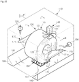
- a heat treatment apparatus includes a heating furnace 110 which accommodates a coil 120, which is wound, a heating apparatus 130 which heats an inner portion of the heating furnace 110, a circulation apparatus 140 which circulates heat in the heating furnace 110, a coil support apparatus 150 installed at a bottom of the heating furnace 110, and flow guide portions 170 which guide a portion of the circulating heat to a hollow portion 122 of the coil 120.
- the heating furnace 110 may have a wall provided with an iron shell 110a and refractory material 110b, and include a structure in a hexahedral shape in which a heating space, which accommodates the coil 120 therein, is formed.
- a heating space which accommodates the coil 120 therein, is formed.
- an opening may be formed at sidewalls 113 and 114 or an upper wall 111 for moving the coil 120 into the heating space or discharging the coil 120 in the heating space, and the opening may be opened or closed by a door or a cover.
- the coil 120 accommodated in the heating furnace 110 may be loaded on the coil support apparatus 150 so that a circumferential surface 121 of the coil 120 is disposed at a central portion of a bottom 112 of the heating furnace, and both side surfaces 123 and 124 of the coil 120 may be disposed to respectively face the sidewalls 113 and 114 of the heating furnace 110. Open both ends of the hollow portion 122 of the coil 120 respectively face the sidewalls 113 and 114 of the heating furnace 110.
- the heating apparatus 130 may include burners which heat the heating space to a temperature for heat treatment of the coil 120 by jetting flames into the heating space.
- a plurality of heating apparatuses 130 may be installed at the upper wall 111 or the sidewalls 113 and 114 of the heating furnace 110 to uniformly heat the heating space, however, an installation position, the number of installations, and the like are not limited to the disclosed embodiment.
- the circulation apparatus 140 may include a blower fan 141 disposed at an upper portion of the heating space adjacent to one sidewall and configured to blow heat downward, and a driving motor 142 installed at an upper portion of the heating furnace 110 to drive the blower fan 141.
- the circulation apparatus 140 blows heat toward the bottom 112 of the heating furnace 110 from the upper portion of the heating furnace 110 through a space between one side surface 123 of the coil 120 and the sidewall 113 of the heating furnace 110. Accordingly, the blown heat heats a side of the one side surface 123 of the coil 120 while descending from the circulation apparatus 140, and switches a direction and flows to the opposite side through a lower portion of the coil 120 when it arrives at the bottom of the heating furnace 110. Subsequently, the heat rises to heat a side of the opposite side surface 124 the coil 120.
- the circulation apparatus 140 is installed at the upper wall 111 of the heating furnace 110 as an example, the installation position and the number of the circulation apparatuses 140 may vary, and thus a flow and a circulation direction of heat may vary.
- the flow guide portions 170 may be respectively installed at the both sidewalls 113 and 114 of the heating furnace 110, and cause the hollow portion 122 to be easily heated by guiding a portion of the heat flowing around the coil 120 to the hollow portion 122 of the coil 120.
- the flow guide portions 170 positioned at both sides of the heating furnace 110 include guide boards 171 extending from the heating furnace sidewalls 113 and 114 facing the side surfaces 123 and 124 of the coil 120 toward the hollow portion 122 of the coil 120.
- the guide boards 171 include inclined guide surfaces 171 a and 171b disposed to face a flow direction of heat flowing due to an operation of the circulation apparatus 140.
- the inclined guide surfaces 171 a and 171 b maintain inclinations at a predetermined angle with respect to a central line 125 of the coil 120 to guide flowing heat to the hollow portion 122 of the coil 120.
- coupling ends 171c coupled to the sidewalls 113 and 114 of the heating furnace 110 have a thicker thickness than free ends 171 d facing the hollow portion 122 of the coil 120 (a wedge shape). Accordingly, the inclined guide surfaces 171 a and 171b are naturally formed at upper surfaces and lower surfaces of the guide boards 171, respectively. Since such a shape has a bending stress which increases toward the coupling ends 171c, the free ends 171 d may be prevented from sagging.
- a portion of heat descending from the circulation apparatus 140 may be guided to naturally curve toward the hollow portion 122 of the coil by an upper side inclined guide surface 171 a of the guide board 171 (a right guide board in the drawing) coupled to one sidewall 113, and may enter the hollow portion 122 of the coil.
- a portion of heat rising from the opposite side after flowing through the lower portion of the coil 120 naturally curves due to a guide of a lower side inclined guide surface 171b of the guide board 171 (a left guide board in the drawing) coupled to the opposite sidewall 114 and may enter the hollow portion 122 of the coil 120.
- heat introduced from both sides of the hollow portion 122 of the coil into the hollow portion 122 increases a heating effect of the hollow portion 122 of the coil by forming a flow field which rotates in the hollow portion 122.
- the embodiment describes the case that the inclined guide surfaces 171 a and 171b of both of the sides guide boards 171 are disposed to respectively face the upper portion and the lower portion of the heating furnace 110 to guide descending heat or rising heat in the heating furnace 110 to the hollow portion 122 of the coil, when a flow direction of the heat is changed due to a position change of the circulation apparatus 140 and the like, the inclined guide surfaces 171 a and 171 b of the guide board 171 may also be disposed to face the flowing heat.
- the embodiment describes a case in which the inclined guide surfaces 171 a and 171b are formed at the upper surface and the lower surface of the guide board 171 to have shapes which correspond to each other, the inclined guide surfaces may also be formed at only one side surface which faces flowing heat.
- the embodiment describes the case that the guide boards 171 are respectively installed at the both sidewalls 113 and 114 of the heating furnace 110, even when the guide board 171 is installed at any one side, the hollow portion 122 may also be heated by heat being guided to the hollow portion 122 of the coil.
- a width of the guide board 171 narrows from the coupling end 171 c coupled to the sidewall 113 of the heating furnace 110 to the free end 171 d (a width from the left to the right thereof in the drawing). Accordingly, a portion of the descending heat may flow to the hollow portion 122 of the coil, and the remaining portion may bypass the both sides of the guide board 171 to flow toward the lower portion of the coil 120. In a similar way, a portion of the rising heat at the opposite side may flow to the hollow portion 122 of the coil, and the remaining portion may flow toward the upper portion of the coil 120.
- the reason why the guide board 171 is formed with such a structure is that when the free end 171 d has an excessively large width, the guide board 171 may block descending or rising heat and hinder the uniform heating of the coil 120.
- the free end 171 d of the guide board 171 have a width equal to a diameter of the hollow portion 122 of the coil 120 or less than a diameter of the hollow portion 122. The reason for this is that although the free end 171 d has a width greater than the diameter of the hollow portion 122 of the coil, a flow guided to the hollow portion 122 of the coil is not increased, but, the flow which bypasses the both sides of the guide board 171 is hindered.
- the minimum width of the coupling end 171 c of the guide board 171 be greater than or equal to the diameter of the hollow portion 122 of the coil, and the maximum width be less than or equal to an external diameter of the coil 120.
- the guide board 171 may have a rectangular shape as in an illustrated example in FIG. 29 . Since a flow which by passes the guide board 171 may be hindered when the width of the coupling end 171c is greater than the external diameter of the coil 120, and thus is not preferable.
- the guide board 171 be disposed at a height between a center of the coil 120 and an upper end of the hollow portion 122 of the coil when guiding flowing heat. In addition, it is preferable that the guide board 171 be disposed at a height between the center of the coil 120 and a lower end of the hollow portion 122 of the coil when guiding heat rising through the lower portion of the heat coil 120.
- Heat descending from the circulation apparatus 140 is curved to be introduced toward a lower half portion of the hollow portion 122 of the coil by the guiding of the guide board 171. Accordingly, since a flow does not face the hollow portion 122 and faces downward by coming into contact with the side surface 123 of the lower portion of the coil 120 when a height of the guide board 171 is lower than the center of the coil 120, a heating effect of the hollow portion 122 is not great. Conversely, since the side surface 123 of the upper portion of the coil 120 hinders a flow facing the hollow portion 122 when the height of the guide board 171 is higher than the upper end of the hollow portion 122 of the coil, a heating effect of the hollow portion 122 is not great.
- the heat treatment apparatus includes corner guide portions 180 disposed at both corners where the bottom 112 and the sidewalls 113 and 114 of the heating furnace 110 meet and having flow guide surfaces 181 which switch a flow direction of heat.
- One side corner guide portion 180 guides heat descending toward the bottom 112 of the heating furnace 110 toward the lower portion of the coil 120, and the other side corner guide portion 180 guides heat passing through a lower side of the coil 120 in an upper direction.
- the corner guide portions 180 may be provided to have a length corresponding to a width of the sidewalls 113 and 114 of the heating furnace 110, and the flow guide surfaces 181 may have inclined flat surfaces with respect to the bottom of the heating furnace for seamless direction switching of heat.
- FIG. 26 is a view illustrating a case when a flow guide surface 182 has an inclined inward curving surface as a modified example of the corner guide portion 180. According to such a corner guide portion 180, since heat which circulates in the heating furnace 110 may switch a direction while maintaining a flow speed, heat may be smoothly circulated.
- the coil support apparatus 150 disposed at a side of the bottom 112 of the heating furnace 110 includes ventilating air paths 152, 153, and 154 formed in multiple directions for heat ventilation.
- the coil support apparatus 150 includes a plurality of support blocks 151 disposed to be spaced apart from each other to secure the ventilating air paths 152 and 153, a plurality of separating members 155 mounted on each of top surfaces of the support blocks 151 to be separated from each other and configured to support the coil 120 and separate the coil 120 from the top surface of the support block 151.
- the support blocks 151 may have lower portions which are connected to each other by a connecting plate 156.
- Each support block 151 may be formed to have a hexahedral structure for supporting a weight of the coil 120, which is about 35 tons.
- the ventilating air paths 154 which communicate with each other, are formed at a plurality of side surfaces 151 b and a top surface 151 a.
- the ventilating air paths 152 and 153 are secured by the plurality of support blocks 151 being separately disposed from each other, and at the same time, the ventilating air paths 154 through which the side surfaces and the top surface communicate with each other are formed in the support blocks 151, flowing heat may easily approach a lower side of the circumferential surface 121 of the coil 120.
- the lower portion of the coil 120 may be smoothly heated by circulating heat even in a state in which the circumferential surface 121 of the lower side of the coil 120 is supported by the coil support apparatus 150.
- FIG. 28 is a view illustrating an example of a modified separating member.
- each separating member 158 may be provided to have an external surface in a semi-cylindrical shape coming into contact with the circumferential surface 121 of the coil 120.
- Such a separating member 158 may cause the circumferential surface 121 of the coil 120 and the separating member 158 to come into contact with each other in advance to decrease a support area, and thus may cause heat to more smoothly approach the circumferential surface 121 of the lower side of the coil.
- the flow guide portion 170 including the guide board 171 guides a portion of heat flowing around the coil 120 to the hollow portion 122 of the coil 120, a temperature deviation between the external surface of the coil 120 and the hollow portion 122 may be minimized during heating of the coil 120.
- heat may smoothly approach the circumferential surface 121 of the lower side of the coil 120 through the multi-directional ventilating air paths 152, 153, and 154 formed in the coil support apparatus 150, a temperature deviation between the upper portion and the lower portion of the coil 120 may also be minimized. Accordingly, by entirely uniformly heating the coil 120, a uniform heat treatment effect may be obtained.
- FIG. 30 is a view illustrating an example of a modified guide board of the flow guide portion 170.
- inclined guide surfaces 271 a and 271 b of an upper side and lower side of a guide board 271, respectively, are provided in as inward curving surfaces.
- the guide board 471 may also be provided such that a coupling end 271 c has a thicker thickness than that of a free end 271 d, and the coupling end 271 c has a width less than that of the free end 371d.
- central portions thereof may have a thickness less than that of both side ends.
- FIG. 31 is a view illustrating an example of a modified flow guide portion.
- a flow guide portion 370 includes a coupling member 372 mounted on a sidewall 113 of a heating furnace 110, and configured to rotatably support a coupling end of a guide board 371, and a support portion 373 which supports the guide board 371 in a state in which an angle is adjusted.
- the angle of the guide board 371 may be adjusted by lowering or raising a height of a free end 371 d when necessary. Accordingly, a flow direction of heat flowing toward the hollow portion 122 of a coil may be adjusted by adjusting the angel of the guide board 371 when a coil which has a different specification is heated.
- the guide board 371 Since one end of the support portion 373 is rotatably connected to a lower surface of the guide board 371 and the other end is rotatably connected to the coupling member 372, the guide board 371 may be supported in a fixed state.
- the support portion 373 may have a turnbuckle type capable of adjusting the length thereof to adjust the angle of the guide board 371.
- the support portion 373 may be replaced with another support portion which has a different length when the angle of the guide board 371 needs to be adjusted.
- FIG. 32 is a view illustrating another example of a modified flow guide portion.
- a flow guide portion 470 may include a guide rail 474 installed on a sidewall 113 of a heating furnace 110, a coupling member 472 movably installed at the guide rail 474 and configured to rotatably support a coupling end of a guide board 471 for adjusting an angle of the guide board 471, a movement apparatus 475 moving the coupling member 472, and a support portion 473 which supports the guide board 471 in a state in which the angle is adjusted. That is, the angle and a height of the guide board 471 may be adjusted when necessary.
- the movement apparatus 475 may include a screw shaft 475a rotatably supported in a coupled state to the coupling member 472 and extended in a direction in which the guide board 471 moves (along a longitudinal direction of the guide rail), and a rotating means which rotates the screw shaft 475a.
- the rotating means may include a rotating handle 475b provided at one end of the screw shaft 475a, a driving motor (not shown) which rotates the screw shaft 475a, or the like.
- the movement apparatus having a screw shaft method is described as an example, the movement apparatus may be changed variously such as a chain-sprocket method, and a rack and pinion method.
- the height and the angle of the guide board 471 may be adjusted, this may be slightly modified such that the guide board 471 is also fixed to the coupling member 472.
- the angle of the guide board 471 cannot be adjusted, rather the height may be adjusted by operating the movement apparatus 475, and thus a direction of heat flowing toward a hollow portion 122 of a coil may be adjusted.
- twist and appearance failures due to a material quality deviation during cold rolling may be prevented by decreasing the material quality deviation along a width direction of a hot coil of AHSS.
- the heat treatment apparatus in accordance with one embodiment of the present disclosure guides a portion of heat flowing around the coil to the hollow portion of the coil, a temperature deviation between the external surface and the hollow portion of the coil can be minimized. Accordingly, the entire coil is uniformly heated and a uniform heat treatment effect can be achieved.
Landscapes
- Chemical & Material Sciences (AREA)
- Engineering & Computer Science (AREA)
- Mechanical Engineering (AREA)
- Materials Engineering (AREA)
- Crystallography & Structural Chemistry (AREA)
- Thermal Sciences (AREA)
- Physics & Mathematics (AREA)
- Metallurgy (AREA)
- Organic Chemistry (AREA)
- Heat Treatment Of Strip Materials And Filament Materials (AREA)
- Winding, Rewinding, Material Storage Devices (AREA)
- Metal Rolling (AREA)
- Heat Treatments In General, Especially Conveying And Cooling (AREA)
Abstract
Description
- This application claims the benefit of Korean Patent Application No.
2014-0175568, filed on December 09, 2014 2014-0177699, filed on December 10, 2014 2015-0080524, filed on June 08, 2015 - Embodiments of the present disclosure relate to a heat treatment method of a hot coil and a heat treatment apparatus which heats a wound coil and performs a heat treatment.
- A hot rolling process performed in a steel manufacturing process reheats a slab manufactured in a blast furnace and the like to a temperature suitable for rolling in a heating furnace or the like in which the slab was manufactured, and the slab is rolled into a hot rolled steel sheet in a strip shape through a series of rolling apparatuses such as a roughing mill, a finishing mill, and the like, and is wound in a coil shape by a winder after being cooled by a cooling machine. Then, the wound hot coil is stacked on a yard and shipped to a cold rolling factory or as a product after an air cooling process.
- A material quality deviation is generated between an edge of the hot coil in contact with the atmosphere and an inner portion of the hot coil due to a cooling speed difference in the air cooling process, and the material quality deviation causes a coil break or a tipping effect during the subsequent cold rolling process and generates manufacturing difficulties.
- Meanwhile, a strip produced through the hot or cold rolling is wound in a coil shape for transferring or storing. After winding, in many cases, the heat treatment is performed on the wound strip coil by heating to decrease a material quality deviation or obtain a required physical characteristic.
- A batch method, which accommodates a wound coil in a heating machine and heats the wound coil, and a continuous method, which heats a strip while the strip is being unwound from a coil state and is being transferred, have been known as a method for heating a strip. From these, the batch method is capable of heating a strip in a coil state and has a merit in that it does not need a machine for winding and unwinding the coil and the size of a machine can be small compared to the continuous method because a space for the strip is not large.
- A conventional batch type coil heating machine includes a heating furnace accommodating a coil therein, a heating apparatus which heats the inside of the heating furnace, a circulation fan which circulates heat in the inside of the heating furnace, and a coil skid provided on the bottom of the inside of the heating furnace for stacking the coil.
- Such a coil heating machine heats a coil stacked in the heating furnace by heat inside the heating furnace being circulated inside the heating furnace by a circulation fan. A conventional coil heating machine includes a type in which the circulation fan blows heat downward from an upper portion of the heating furnace.
- The circulating heat heats one side of a coil while flowing down from a blower fan, and heats the opposite side of the coil when it changes a direction by arriving at the bottom of the heating furnace and then flows toward the opposite side thereof, and rises. Overall, the circulating heat circulates by surrounding a circumference of the coil. A portion of heat heats a hollow portion of the coil while flowing toward the opposite side by passing through the hollow portion (the inner wound portion).
- However, in such a coil heating machine, since most of the heat flows an outer side surface and a circumferential surface of the coil, the heat flowing in the hollow portion of the coil is negligible. In addition, since a lower surface of the coil is hidden by the coil skid, heat cannot arrive the lower surface. Accordingly, it is difficult to uniformly heat the entire coil, and thus there is a limitation in obtaining a totally uniform heat treatment effect.
- Therefore, it is an aspect of the present disclosure to provide a heat treatment method which may decrease a material quality deviation in a width direction of a hot coil of an advanced high strength steel (AHSS) and a cold rolling method using the same.
- It is another aspect of the present disclosure to provide a heat treatment apparatus which may uniformly heat an entire coil and obtain a uniform heat treatment effect.
- Additional aspects of the disclosure will be set forth in part in the description which follows and, in part, will be obvious from the description, or may be learned by practice of the disclosure.
- In accordance with one aspect of the present invention, a heat treatment method of a hot coil of an advanced high strength steel (AHSS) comprises performing a hot rolling on a rolled material, cooling and winding the rolled material, forming the hot coil, performing a first cooling on the hot coil to a temperature at which a phase transformation is completed such that a hard phase is generated at an edge portion of the hot coil, heating only the edge portion of the hot coil and increasing a temperature of the edge portion of the hot coil to a tempering temperature, maintaining the tempering temperature for a predetermined time, weakening a strength of the edge portion of the hot coil such that the edge portion of the hot coil which was processed in the performing of the first cooling has a strength similar to that of a central portion of the hot coil and performing a second cooling of the hot coil which was processed in the weakening of the strength of the hot coil edge.
- In the weakening of the strength of the edge of the hot coil, the tempering temperature may be in the range of 400 to 700 °C.
- A temperature of the hot coil which is completely wound in the forming of the hot coil may be in the range of 500 to 700 °C.
- In the performing of the first cooling, a temperature at which the phase transformation is completed may be in the range of room temperature to 400 °C.
- In the performing of the first cooling, a width of the edge portion of the hot coil may include a region of one fourth of an entire width of the hot coil.
- A tensile strength of the hot coil may be 780 MPa or more.
- The heating in the weakening of the strength of the edge portion of the hot coil may include rapidly heating the hot coil such that a region of one fourth of an entire width of the hot coil from an edge of the hot coil along a width direction of the hot coil reaches the tempering temperature.
- In the weakening of the strength of the edge of the hot coil, the predetermined time may be set to be in the range which is defined by a following equation.

- The temperature may be the tempering temperature and 7600≤X≤8600.
- The performing of the second cooling may include cooling the edge portion of the hot coil at a cooling speed of 3 °C/min or more.
- In accordance with another aspect of the present invention, a cold rolling method which manufactures a cold-rolled steel sheet from a hot coil of an AHSS having a tensile strength of 780 MPa or more, the method comprises performing a first cooling of an edge portion of the hot coil of the AHSS which has a winding temperature of in the range of 500 to 700 °C to in the range of room temperature to 400 °C and completing a phase transformation of the edge portion into a hard phase, reheating only the edge portion which is completely phase transformed into hard phase, maintaining a temperature in the range of 400 to 700 °C for in the range of 30 to 480 minutes, weakening a strength, performing a second cooling of the hot coil of the AHSS whose strength was weakened at a speed of 3 °C/min or more and performing a cold rolling.
- In accordance with another aspect of the present invention, a heat treatment apparatus which performs a heat treatment of a hot coil, comprising a heat treatment furnace including a heating chamber into which transfer carts which stack and transfer the hot coil come and a plurality of heating means installed at thermal insulation wall surfaces forming the heating chamber and configured to heat the hot coil, wherein the plurality of heating means include first burners installed in the heating chamber to control a temperature of the heating chamber, second burners installed on both sidewalls of the heating chamber to heat both side surfaces of the hot coil, and hot blast supply portions which supply hot blast toward an inner wound portion of the hot coil.
- The hot blast supply portions may collect high temperature exhaust gas discharged from the heating chamber and may jet the gas toward the inner wound portion of the hot coil.
- Each of the first burners may include a flame burner, and the flame burner may be installed on an upper wall of the heating chamber such that jetted flames are not in direct contact with the hot coil.
- Each of the second burners may include a radiant burner which heats the both side surfaces of the hot coil with radiant heat, and at least one radiant burner may be disposed on the sidewall to face a side surface between a center and a lower end of the hot coil.
- Each of the hot blast supply portions may include a nozzle which jets hot blast toward the inner wound portion of the hot coil, a collection pipe connected to an exhaust pipe through which a high temperature gas in the heating chamber is discharged and configured to supply the exhaust gas flowing in the exhaust pipe to the nozzle, a damper which adjusts a supply of the exhaust gas from the exhaust pipe to the collection pipe and a blast fan which supplies a blast force which transfers the exhaust gas flowing in the collection pipe toward the nozzle.
- The heat treatment furnace includes a main body in a tunnel shape including an upper wall and the both sidewalls such that a front surface, a rear surface, and a lower portion of the heat treatment furnace is open, wherein the open lower portion may be closed by the transfer cart when the transfer cart enters the heating chamber, and the open front surface and the rear surface may be closed by opening and closing doors installed at the heat treatment furnace.
- The heating chamber may be formed to have an insulated structure by the upper wall and the both sidewalls which are formed with the thermal insulation wall surface, and a thermal insulation panel disposed at a top surface of the transfer cart.
- The heat treatment apparatus may further comprise a sealing apparatus which seals a gap between the both sidewalls and the transfer cart when the transfer cart enters the heating chamber.
- The sealing apparatus may include a rotating arm rotatably coupled to one side of a lower end of the sidewall of the main body and including a thermal insulation member configured to seal the gap and a driving unit which drives the rotating arm such that the thermal insulation member moves between a first position to seal the gap and a second position to be spaced apart from the gap.
- The heat treatment apparatus may further comprise a controller configured to control a temperature in the heating chamber, wherein the controller may control the plurality of heating means to maintain the temperature in the heating chamber to be higher than a heating target temperature of the hot coil at an initial stage of heating the hot coil, and to maintain the temperature in the heating chamber at the heating target temperature after a predetermined time has passed.
- Two transfer carts which are installed to be movable along a rail from both sides of the heat treatment furnace may be provided, and the two transfer carts may alternatively enter and exit the heating chamber.
- In accordance with another aspect of the present invention, a heat treatment apparatus comprises a heating furnace which accommodates and heats a wound coil, a circulation apparatus which circulates heat in the heating furnace and flow guide portions which guide a portion of heat flowing around the coil in the heating furnace to a hollow portion of the coil.
- Each of the flow guide portions may include a guide board extending from a sidewall of the heating furnace facing a side surface of the coil toward the hollow portion of the coil.
- The guide board may include an inclined guide surface inclined with respect to a central line of the coil to guide flowing heat to the hollow portion of the coil.
- The guide board may be formed such that a coupling end coupled to the sidewall of the heating furnace may have thicker thickness than a free end facing the hollow portion of the coil.
- The guide board may be provided such that a free end facing the coil hollow portion may have a width equal to or less than a diameter of the hollow portion of the coil.
- The guide board may be provided such that a coupling end coupled to the sidewall of the heating furnace may have a minimum width equal to or greater than a diameter of the hollow portion of the coil and has a maximum width equal to or less than an outer circumferential diameter of the coil.
- The flow guide portions may be respectively installed on both sidewalls of the heating furnace facing both side surfaces of the coil.
- The inclined guide surface may be provided in a curved shape.
- Each of the flow guide portions may further include a coupling member installed at the sidewall of the heating furnace and configured to rotatably support a coupling end of the guide board to adjust an angle of the guide board and a support portion which supports the guide board in a state in which the angle of the guide board is adjusted.
- Each of the flow guide portions may further include a guide rail installed on the sidewall of the heating furnace, a coupling member which is movably coupled to the guide rail and configured to support a coupling end of the guide board and a movement apparatus which moves the coupling member.
- The circulation apparatus may be disposed to blow heat from an upper portion of the heating furnace through a space between one side surface of the coil and a sidewall of the heating furnace toward a bottom of the heating furnace.
- A guide board may be disposed at a height between a center of the coil and an upper end of the hollow portion of the coil when guiding descending heat, and may be disposed at a height between the center of the coil and a lower end of the hollow portion of the coil when guiding rising heat which passes through a lower portion of the coil.
- The heat treatment apparatus may further comprise a corner guide portion provided at a corner at which the bottom of the heating furnace and the sidewall of the heating furnace meet, and including a flow guide surface inclined with respect to the bottom of the heating furnace to switch a flow direction of the heat.
- The heat treatment apparatus may further comprise a coil support apparatus which is disposed at a side of a bottom of the heating furnace and supports a circumferential surface of a lower side of the coil, wherein a ventilating air path configured to flow heat in multiple directions is formed in the coil support apparatus.
- The coil support apparatus may include a plurality of support blocks disposed to be spaced apart from each other and each including the ventilating air path through which a side surface and a top surface are communicated with each other and a plurality of separating members which are installed at the top surface of the support blocks to be separated from each other, support the coil, and separate the coil and the top surface of the support blocks.
- In accordance with another aspect of the present invention, a heat treatment apparatus comprises a heating furnace which accommodates and heats a wound coil, a circulation apparatus which circulates heat in the heating furnace and a coil support apparatus which is disposed at a side of a bottom of the heating furnace and supports a circumferential surface of a lower side of the coil, wherein a ventilating air path configured to flow heat in multiple directions is formed in the coil support apparatus.
-
-
FIG. 1 is a view illustrating a hot rolling process according to an embodiment of the present disclosure. -
FIG. 2 is a flow chart of a heat treatment method according to the embodiment of the present disclosure. -
FIG. 3 is a view illustrating a temperature change during a heat treatment process according to the embodiment of the present disclosure. -
FIG. 4 is a graph illustrating a strength in a width direction of a hot coil before a heat treatment according to the embodiment of the present disclosure. -
FIG. 5 is a graph illustrating a strength according to a reheating starting temperature of a heat treatment after a heat treatment according to the embodiment of the present disclosure. -
FIG. 6 is a graph illustrating a strength variation according to a pre-heat treatment microstructure, a heat treatment temperature, and a heat treatment time according to the embodiment of the present disclosure, -
FIG. 7 is a graph in which a combined variable of the temperature and the time of the graph inFIG. 6 is plotted on an x-axis. -
FIG. 8 is a graph illustrating whether there is a strength weakening effect according to a maximum temperature of a heat treatment according to the embodiment of the present disclosure. -
FIG. 9 is a graph illustrating a temperature change of two positions which are the edge portion and an inner portion of the hot coil during a heat treatment process. -
FIG. 10 is a graph illustrating a temperature distribution of a hot coil in the width direction during a heat treatment process. -
FIG. 11 is a diagram illustrating a material quality deviation of a hot coil in a width direction in comparison with a conventional case, wherein heat treatment is performed on the hot coil according to the embodiment of the present disclosure. -
FIG. 12 is a schematic view illustrating a heat treatment apparatus according to a first embodiment of the present disclosure. -
FIG. 13 is a view when a transfer cart according to the first embodiment of the present disclosure enters a heat treatment furnace. -
FIG. 14 is a schematic view illustrating a sealing apparatus according to the first embodiment of the present disclosure. -
FIG. 15 is cross-sectional view illustrating an internal structure of the heat treatment furnace according to the first embodiment of the present disclosure. -
FIG. 16 is a view illustrating an arrangement structure of a radiant burner according to the first embodiment of the present disclosure. -
FIG. 17 is a schematic view illustrating a hot blast supply portion according to the first embodiment of the present disclosure. -
FIG. 18 is a control block diagram illustrating a temperature control of a heating chamber according to the first embodiment of the present disclosure. -
FIG. 19 is a graph illustrating two steps of temperature control of a heating chamber according to the first embodiment of the present disclosure. -
FIG. 20 is a graph illustrating a temperature change at a surface of the hot coil when a temperature control of a heating chamber is performed according to the first embodiment of the present disclosure. -
FIG. 21 is a view illustrating two transfer carts installed both sides of the heat treatment furnace according to the first embodiment of the present disclosure. -
FIG. 22 is a perspective view illustrating a heat treatment apparatus according to a second embodiment of the present disclosure. -
FIG. 23 is a cross-sectional view taken along a line II-II' ofFIG. 22 . -
FIG. 24 is a perspective view of a guide board of a flow guide portion of the heat treatment apparatus according to the second embodiment of the present disclosure. -
FIG. 25 is a perspective view of a corner guide portion of the heat treatment apparatus according to the second embodiment of the present disclosure. -
FIG. 26 is a perspective view illustrating an example of a modified corner guide portion of the heat treatment apparatus according to the second embodiment of the present disclosure. -
FIG. 27 is a perspective view illustrating a coil support apparatus of the heat treatment apparatus according to the second embodiment of the present disclosure. -
FIG. 28 is a view illustrating an example of a modified separating member mounted on the support block of the heat treatment apparatus according to the second embodiment of the present disclosure. -
FIGS. 29 and30 are views illustrating examples of a modified guide board of the flow guide portion according to the second embodiment of the present disclosure. -
FIGS. 31 and32 are views illustrating examples of a flow guide portion according to the second embodiment of the present disclosure. - Hereinafter, embodiments of the present disclosure will be described in detail with reference to following drawings. The following drawings are examples which provide the scope of the present disclosure to those skilled in the art. The present disclosure is not limited to the following embodiments and may be implemented in different forms. Parts irrelevant to description are omitted in the drawings in order to clearly describe the present disclosure, and widths, lengths, and thicknesses of components in the drawings may be exaggerated for convenience of description. In this specification, like reference characters denote like components
-
FIG. 1 is a view illustrating a hot rolling process according to an embodiment of the present disclosure,FIG. 2 is a flow chart of a heat treatment method according to the embodiment of the present disclosure, andFIG. 3 is a view illustrating a temperature change during a heat treatment process according to the embodiment of the present disclosure. - Referring to
FIGS. 1 to 3 , a cold rolling method according to an embodiment of the present disclosure includes forming a hot coil (S10), performing a first cooling (S20), weakening an edge strength of the hot coil (S30), performing a second cooling (S40), and performing a cold rolling (S50). - The forming of the hot coil (S10) includes rolling a slab S1 and manufacturing a
hot coil 20 which is an advanced high strength steel (AHSS) that is wound in a final coil shape and has a tensile strength of 780 MPa or more. Specifically, the slab S1 is heated to a suitable temperature for rolling in aheating furnace 10, a bar S2 type is formed by performing width rolling and thickness rolling on the heated slab S1, which was heated in theheating furnace 10, in a rough rollingmachine 11 including three to four rolling stands, and then a strip S3 may be rolled to have a required thickness by afinishing rolling machine 12 including six to seven rolling stands performing a last thickness rolling to the required thickness. Next, the strip S3 is supplied to awinder 14 after being cooled to a predetermined temperature while passing through acooling process 13, and thewinder 14 may wind the completely cooled strip S3 into a coil form and form thehot coil 20. Hereinafter, the slab S1, the bar S2, and the strip S3 are referred to as a rolled material S. The rolled material S includes a dualphase (DP) steel, and a transformation induced plasticity (TRIP) steel which are rolled AHSS and have a tensile strength of 780 MPa or more. In addition, a temperature T1 of thehot coil 20 may be in the range of 500 to 700 °C when thehot coil 20 is wound by thewinder 14 after the hot rolling process. - The performing of the first cooling S20 includes cooling the
hot coil 20 to a temperature at which a phase transformation is completed and an adequate cooling speed is maintained such that a hard-phase (martensite and bainite) is formed at an edge portion of thehot coil 20 wound by thewinder 14. - The temperature at which the phase transformation is completed in the performing of the first cooling S20 may correspond to a reheating starting temperature T2 of a heat treatment in
FIG. 3 , and may be included in the range of room temperature to 400 °C. At this point, the temperature at which the phase transformation is completed will be described with reference toFIGS. 4 and5 .FIG. 4 is a graph illustrating a strength in a width direction of a hot coil before a heat treatment according to the embodiment of the present disclosure, andFIG. 5 is a graph illustrating a strength according to a reheating starting temperature of a heat treatment after a heat treatment according to the embodiment of the present disclosure. As illustrated inFIG. 5 , when the reheating starting temperature is 400 °C or less, strength is weakened after the heat treatment compared with strength of the hot coil before the heat treatment inFIG. 4 , however, when the reheating starting temperature is 400 °C or more, the strength is not greatly weakened. The reason for this is that when the reheating starting temperature is 400 °C or more, the phase transformation is not totally completed, and hard-phase is formed again in the performing of the second cooling S40 after reheating in the same way as in the forming of the hot coil S10. Accordingly, it is preferable that the first cooling S20 be performed to cool thehot coil 20 to 400 °C or less which completes the phase transformation at the edge portion of thehot coil 20. At this point, the performing of the first cooling S20 may cool thehot coil 20 to a temperature at which the phase transformation is completed using a temperature difference between room temperature and the hot coil in a state in which the coil is stacked on a yard of a factory or a bottom of a coil storage. - The weakening of the edge strength of the hot coil S30 includes performing a heat treatment which heats the hard-phase of the edge portion of the
hot coil 20, which was formed through the performing of the first cooling S20, and increases a temperature of the edge portion of thehot coil 20 to a tempering temperature T3, and then maintains the tempering temperature T3 for a predetermined time such that the edge portion of thehot coil 20 has a strength similar to that of a central portion of thehot coil 20. - Specifically, the weakening of the edge strength of the hot coil S30 includes heating only the edge portion of the
hot coil 20 and increasing the temperature of the edge portion of thehot coil 20 to the tempering temperature T3 (for example, 400 to 700 °C) (S31), and temperature maintaining which maintains the tempering temperature T3 for the predetermined time required for a tempering effect to occur (S32). - The heating S31 may heat the
hot coil 20 such that a temperature of a region which is one fourth or more of the entire width of thehot coil 20 in the width direction of thehot coil 20 from the edge of the hot coil 20 (a border at which strength becomes high due to the hard-phase illustrated inFIG. 4 ) reaches the tempering temperature T3. - The temperature maintaining S32 weakens the
hot coil 20 such that the edge portion of thehot coil 20 has a strength similar to that of the central portion of thehot coil 20 by the temperature of the edge portion of the hot coil 20 (for example, the region of one fourth of the entire width) reaching the tempering temperature T3 and the tempering temperature T3 being maintained for the predetermined time. - At this point, a relation between the tempering temperature T3 and a maintenance time of the tempering temperature T3 will be described with reference to
FIGS. 6 to 8 .FIG. 6 is a graph illustrating a strength variation according to a pre-heat treatment microstructure, a heat treatment temperature, and a heat treatment time according to the embodiment of the present disclosure,FIG. 7 is a graph in which a combined variable of the temperature and the time of the graph inFIG. 6 is plotted on an x-axis, andFIG. 8 is a graph illustrating whether there is a strength weakening effect according to a maximum temperature of a heat treatment according to the embodiment of the present disclosure. - First, referring to
FIG. 6 , a pre-heat treatment microstructure is classified into three, a ferrite plus martensite (F+M), a ferrite plus pearlite (F+P), and a ferrite plus pearlite (As-R, a position of one fourth of an air cooled coil after rolling), and the F+M corresponds to the edge of the coil, the As-R corresponds to the central portion of the coil, and the F+P corresponds to a structure between the edge and the central portion of the coil. At this point, when the heat treatment temperature is 400 °C, a strength weakening effect is not great in the F+M and the F+P cases no matter how much time increases. Conversely, the strength thereof greatly decreases in a short time when the heat treatment temperature is maintained at a higher temperature. - Referring to
FIG. 7, FIG. 7 is a graph in which the combined variable of the temperature and the time of the graph inFIG. 6 is plotted on the x-axis, wherein the temperature, the time, and strength data of a specific microstructure forms one line. The combined variable of the temperature and the time is defined as X (Hollomon-Jaffe parameter) below.
- At this point, although initial strengths are different according to microstructures, strengths converge on the same strength value as an X value is increased. When the strength value is the same as a strength of the As-R structure, since a material quality deviation in the width direction of a coil disappears, a range of the heat treatment temperature and the heat treatment time may be found based on the X value at this point. However, as illustrated in
FIG. 8 , when the heat treatment temperature is 700 °C or more, since cementite decomposes into austenite and a hard-phase is formed again in the subsequent cooling process, a heat treatment effect disappears. Accordingly, the heat treatment temperature has to be set to 700 °C or less. Accordingly, the tempering temperature T3 may be in the range of 400 to 700 °C. In addition, inFIG. 7 , the maintenance time of the tempering temperature T3 (for example, 600 °C) corresponds to a section in which 7600≤X≤8600, which is a portion (a shadow portion) in which the edge portion and the central portion of thehot coil 20 have the same strength, and when this is substituted intoequation 1,equation 1 becomes 7600 ≤ 873(7.0+log(time)) ≤ 8600, and the maintenance time of the heat treatment may be in the range in which 55.8 min. ≤ time ≤ 709.7 min. At this point, when the maintenance time of the heat treatment is less than approximately 56 min., the heat treatment effect is not great, and when the maintenance time of the heat treatment is greater than 710 min., the strength of the edge portion of thehot coil 20 is excessively weakened and becomes weaker than that of the central portion of thehot coil 20. - Meanwhile, the heating S31 may rapidly heat only the edge portion of the
hot coil 20 to reach the tempering temperature T3 required to weaken a strength of thehot coil 20 so as to minimize internal oxidation of thehot coil 20 due to reheating. Specifically,FIG. 9 is a graph illustrating a temperature change of two positions which are theedge portion ① and aninner portion ② of thehot coil 20 during a heat treatment process. Since thehot coil 20 is heated from the outside in the heat treatment process, a temperature of the edge portion of thehot coil 20 is rapidly increased and reaches an upper temperature limit, which is 700 °C, and the inner portion of thehot coil 20 is slowly heated. At this point, the heat treatment occurs from a time at which each temperature of the positions in the width direction is increased to a lower temperature limit, which is 400 °C. This is illustrated inFIG. 10 , which illustrates a temperature distribution of thehot coil 20 in the width direction. At this point, the heat treatment region is between ① and ②, and a temperature in the region has to be maintained between the upper limit and the lower limit. A position of ② is a border at which a strength is high due to a hard-phase, and a gap between ① and ② has to be greater than one fourth of a width of thehot coil 20 based on the graph inFIG. 4 . The heat treatment time at which the heat treatment temperature of the region of the hot coil between ① and ② is maintained between the upper limit and the lower limit illustrated in the graph inFIG. 9 , is a time from a start of the heat treatment until the heat treatment is completed. Since the entire remaining time in the heating furnace includes time for which a temperature is increasing, the entire remaining time is longer than the real heat treatment time, and is from a heating start until the heat treatment is completed. Accordingly, it is preferable from a viewpoint of suppressing the internal oxidation of thehot coil 20 that a rapid heating be performed such that time between the heating start until reaching the tempering temperature T3 is shortened. - The performing of the second cooling S40 includes cooling the
hot coil 20, which was weakened through the weakening of the edge strength of the hot coil S30, to room temperature. At this point, since a structure of thehot coil 20 is weakened, rehardening according to a cooling speed does not occur. However, to minimize the internal oxidation effect according to the heat treatment, the edge portion of thehot coil 20 may be cooled with a cooling speed which is 3 °C/min or more. -
FIG. 11 is a diagram illustrating a material quality deviation of a hot coil in a width direction in comparison with a conventional case, wherein heat treatment is performed on the hot coil according to the embodiment of the present disclosure. A steel grade of ahot coil 20 is high elongation 980DP, and it has a size of a 2150 mm outer diameter, a 762 mm inner diameter, and a 1200 mm width. Applied heat treatment conditions are cooling at room temperature for 48 hours or more after rolling, and rapidly cooling after reheating at 550 °C and maintaining that temperature for 4 hours. An air cooled material which is not treated at all after rolling has a material quality deviation of about 250 MPa or more between an edge portion and a central portion, and the material quality deviation in a width direction is decreased to 150 MPa or less when a conventional annealing box is used. In addition, when the embodiment of the present disclosure is applied, since great material weakening in the edge portion occurs, a material deviation in the width direction is decreased to 50 MPa or less. - Hereinafter, a heat treatment apparatus according to a first embodiment of the present disclosure will be described.
-
FIG. 12 is a schematic view illustrating a heat treatment apparatus according to the first embodiment of the present disclosure,FIG. 13 is a view when a transfer cart according to the first embodiment of the present disclosure enters a heat treatment furnace. - Referring to
FIG. 12 , aheat treatment apparatus 30 according to the first embodiment of the present disclosure mainly includes atransfer cart 40, and aheat treatment furnace 50. - The
transfer cart 40 may stack and transfer thehot coil 20 formed in the forming of the hot coil S10, and may simultaneously be used for cooling thehot coil 20 in the performing of the first cooling S20. - Such a
transfer cart 40 may include acart body 43 in a flat plate shape in whichwheels 42 moving along arail 41 installed at a factory yard. Thecart body 43 may be moved back and forth along therail 41 by thewheels 42 which are capable of forward and reverse rotation by a driving apparatus (not shown). - The
cart body 43 may be provided of high strength steel or a steel alloy to stably support thehot coil 20, and athermal insulation panel 44 which is formed of a refractory material for thermal insulation may be disposed on a top surface of thecart body 43. - In addition, a plurality of
skids 45 may be disposed on a top surface of thethermal insulation panel 44 for supporting thehot coil 20 by being disposed to be spaced a predetermined distance along a longitudinal direction of the top surface. - A plurality of
hot coils 20 may be cooled when supported by the plurality ofskids 45 before entering theheat treatment furnace 50. - The
transfer cart 40 on which the plurality ofhot coils 20 are seated may move along therail 41 and then enter an inner portion of theheat treatment furnace 50. At this point, thethermal insulation panel 44 of thetransfer cart 40 may form an insulated structure of a lower portion of theheat treatment furnace 50. To this end, thetransfer cart 40 may be provided to have a width slightly less than that of theheat treatment furnace 50, and may have a length slightly greater than that of theheat treatment furnace 50. - Such a
transfer cart 40 may perform a first cooling in a state in which the plurality ofhot coils 20 are supported by theskids 45, when the first cooling is completed, thetransfer cart 40 may move along therail 41 to enter the inner portion of theheat treatment furnace 50 and may form a part of the insulated structure of theheat treatment furnace 50. Accordingly, since an operation in which the plurality ofhot coils 20 are loaded on or unloaded from thetransfer cart 40 for a heat treatment operation is omitted, a standby time of thehot coils 20 for the heat treatment operation may be significantly decreased. - The
heat treatment furnace 50 may be provided in a tunnel shape having a size capable of accommodating thetransfer cart 40. Such aheat treatment furnace 50 includes amain body 51 in a box shape in which a front surface, a rear surface, and a lower portion are open, and an inner portion of themain body 51 may form aheating chamber 60 for heating thehot coil 20 when thetransfer cart 40 enters theheat treatment furnace 50. - When the
transfer cart 40 is inserted into the inner portion of theheat treatment furnace 50, the open lower portion of themain body 51 may be closed by thetransfer cart 40, the open front surface and the rear surface of themain body 51 may be respectively closed by opening andclosing doors 55 installed at themain body 51 to be vertically slidable. - Accordingly, as illustrated in
FIGS. 12 and13 , theheating chamber 60 may form an insulated space sealed by anupper wall 52 of themain body 51, bothsidewalls upper wall 52 to a lower portion, thethermal insulation panel 44 of thetransfer cart 40 which closes the open lower portion of themain body 51, and the opening andclosing doors 55 which close the open front and rear surfaces of themain body 51. - Specifically, when the opening and
closing doors 55 close the open front and rear surfaces of themain body 51, lower ends of the opening andclosing doors 55 may come into contact with thethermal insulation panel 44 of thetransfer cart 40, and thus the opening andclosing doors 55 may seal the open front and rear surfaces of themain body 51. When thetransfer cart 40 enters theheating chamber 60, thethermal insulation panel 44 of thetransfer cart 40 may seal the lower portion of themain body 51, and thus the inner portion of theheat treatment furnace 50 may form a sealedheating chamber 60. - A wall surface of the
heating chamber 60 formed by the opening andclosing doors 55, themain body 51, and thetransfer cart 40 may include a thermally insulated wall surface for preserving heat of an inner portion of theheating chamber 60. That is, since the refractory material is disposed at theupper wall 52 and the bothsidewalls closing doors 55, theheating chamber 60 may form the insulated structure together with thethermal insulation panel 44 of thetransfer cart 40. - At this point, a predetermined gap between the
transfer cart 40 and the bothsidewalls apparatuses 70 may be installed at one side of themain body 51 for sealing the gap. -
FIG. 14 is a schematic view illustrating a sealing apparatus according to the first embodiment of the present disclosure. - Referring to
FIG. 14 , a plurality of sealingapparatuses 70 may be spaced apart from each other along a longitudinal direction of themain body 51 to be respectively installed at lower ends of both sidewalls of themain body 51 and seal a gap t formed between thetransfer cart 40 and the bothsidewalls apparatus 70 installed at onesidewall 53 of themain body 51 will be described. - The sealing
apparatus 70 includes arotating arm 71 rotatably coupled to one side of a lower end of thesidewall 53 of themain body 51, a drivingunit 72 which drives rotation of therotating arm 71, and athermal insulation member 74 disposed at an end portion of therotating arm 71 and capable of moving between a first position, which seals the gap t according to a rotating direction of therotating arm 71, and a second position spaced apart from the gap t. - The driving
unit 72 may include an electric, electronic, hydrodynamic, or pneumatic cylinder including arod 73 which moves back and forth and advances and retreats, and therod 73 may be connected to therotating arm 71 by alink member 75. - The
rotating arm 71 may be installed at the lower portion of thesidewall 53 of themain body 51 to be rotatable about a rotation shaft, one side of therotating arm 71 is hinge coupled to thelink member 75, and thethermal insulation member 74, which is formed to extend a predetermined length along the longitudinal direction of themain body 51, may be provided at the other side. Thethermal insulation member 74 may be separably coupled to the other side of therotating arm 71 to be replaced for maintenance. - With such a structure, when the
transfer cart 40 enters theheating chamber 60, since the gap t formed between thetransfer cart 40 and thesidewall 53 may be sealed by thethermal insulation member 74 installed at an end portion of therotating arm 71 rotated by the drivingunit 72, exhaust gas or heat in theheating chamber 60 is prevented from being leaked to the outside through the gap t. - A plurality of heating means 80 for heat treating the edge portions of the plurality of
hot coils 20 stacked on thetransfer cart 40 after the open portion of themain body 51 is sealed by the opening andclosing doors 55, thetransfer cart 40, and the sealingapparatus 70 are provided in theheat treatment furnace 50. -
FIG. 15 is cross-sectional view illustrating an internal structure of the heat treatment furnace according to the first embodiment of the present disclosure, andFIG. 16 is a view for describing an arrangement structure of a radiant burner according to the first embodiment of the present disclosure. - Referring to
FIGS. 15 and16 , the plurality of heating means 80 according to the first embodiment of the present disclosure includefirst burners 81, which heat inner air of theheating chamber 60 for controlling a temperature of the inner portion of theheating chamber 60,second burners 82 configured to heat both side surfaces of thehot coil 20 arranged in theheating chamber 60, and hotblast supply portions 90 configured to heat aninner wound portion 21 of thehot coil 20 arranged in theheating chamber 60. - The
first burners 81 may include a flame burner (a high speed flame burner) which burns fuel to rapidly heat inner air of theheating chamber 60 with flames. - The
first burners 81 may be installed at theupper wall 52, provided to vertically jet flames, and disposed at positions spaced a predetermined distance (for example, 500 mm or more) from the both side surfaces of thehot coil 20 such that the jetted flames do not directly come into contact with thehot coil 20. The reason for this is to prevent thehot coil 20 from being non-uniform due to a local increase in temperature when the flames jetted from thefirst burners 81 come into direct contact with thehot coil 20. - The
second burners 82 configured to rapidly heat edge portions of both side surfaces ofhot coil 20 may include a radiant burner (a flat flame burner) which burns fuel at a heating surface of a porous flat plate shape and heats the both side surfaces of thehot coil 20 with radiant heat. - The
second burners 82 may be disposed at the bothsidewalls hot coil 20 disposed in theheating chamber 60, and positioned at thesidewall 53 to face a side surface between a center and a lower end of thehot coil 20 as illustrated inFIG. 14 in consideration of a vertical temperature difference of thesecond burners 82 since a discharge pressure of combusted gas is not great due to a structure of the radiant burner, and two or moresecond burners 82 may be provided to be disposed at both left and right sides with respect to the sidewalls of a singlehot coil 20 to uniformly heat thehot coil 20 along a circumferential direction. - The hot
blast supply portions 90 are for heating theinner wound portion 21 of thehot coil 20 which is relatively slowly heated while thehot coil 20 is being heated by high temperature gas in theheating chamber 60. That is, since theinner wound portion 21 of thehot coil 20 is far from the flames of thefirst burners 81 and thesecond burners 82, and is a portion in which a flow of the combusted gas is also imperfect, a heating speed of theinner wound portion 21 is slower than that of the other portions of thehot coil 20. Accordingly, as the hotblast supply portions 90 jet hot blast to theinner wound portion 21 of thehot coil 20, a temperature deviation occurring at theinner wound portion 21 of thehot coil 20 may be decreased. -
FIG. 17 is a schematic view illustrating a hot blast supply portion according to the first embodiment of the present disclosure. - Referring to
FIG. 17 , the hotblast supply portion 90 according to the first embodiment of the present disclosure may be provided to collect a high temperature exhaust gas discharged from theheating chamber 60 and to supply the high temperature exhaust gas to theinner wound portion 21 of thehot coil 20 again. - To this end, the hot
blast supply portion 90 may includenozzles 91 installed at the bothsidewalls inner wound portion 21 of thehot coil 20 disposed in theheating chamber 60,collection pipes 92 connected to anexhaust pipe 59 through which high temperature gas in theheating chamber 60 is discharged and configured to supply the exhaust gas flowing through theexhaust pipe 59 to thenozzle 91, adamper 93 which controls supply of the exhaust gas from theexhaust pipe 59 to thecollection pipes 92, andblast fans 94 which supply a blast force which transfers the exhaust gas flowing through thecollection pipes 92 toward thenozzles 91. - With such a structure, combusted gas generated by the
first burners 81 and thesecond burners 82 is discharged to the outside through theexhaust pipe 59 after heating the both side surfaces and an outer wound portion of thehot coil 20. At this point, the exhaust gas discharged through theexhaust pipe 59 has a high temperature, which is approximately in the range of 700 to 800 °C. In this case, by adjusting an opening degree of thedamper 93 to introduce exhaust gas flowing through theexhaust pipe 59 to thecollection pipes 92 and jetting the exhaust gas toward theinner wound portion 21 of thehot coil 20 through thenozzle 91, the hotblast supply portion 90 may rapidly heat theinner wound portion 21 of thehot coil 20 which is relatively slowly heated. - Hereinafter, a heat treatment method using the heat treatment apparatus according to the first embodiment of the present disclosure will be described.
- First, as illustrated in
FIG. 12 , thehot coil 20 formed in the forming of the hot coil S10 is transferred and stacked on theskid 45 of thetransfer cart 40. - In addition, the
hot coil 20 stacked on thetransfer cart 40 is air cooled while a sufficient cooling speed is maintained until a hard-phase is formed at edge portions of both side surfaces. - Next, the
transfer cart 40 moves along therail 41 to enter the inner portion of theheat treatment furnace 50. - When the
transfer cart 40 completes entering the inner portion of theheat treatment furnace 50, the opening andclosing doors 55 installed at themain body 51 are closed and the sealingapparatuses 70 simultaneously close the gap t between thetransfer cart 40 and the bothsidewalls heating chamber 60 is sealed. - At this point, since there is no need to transfer the
hot coil 20 again for the heat treatment operation as thehot coil 20 was transferred by thetransfer cart 40, heat treatment operation time is decreased. In addition, as illustrated inFIG. 21 , when two ormore transfer carts 40 are provided, while onetransfer cart 40 enters theheat treatment furnace 50 and a heat treatment is performed for thehot coil 20, theother transfer cart 40 performs the first cooling in a state in which thehot coil 20 is loaded, and stands by. Then, when the heat treatment is completed in theheat treatment furnace 50, and onetransfer cart 40 exits, and since theother transfer cart 40 may immediately enter theheat treatment furnace 50, an operation rate of theheat treatment furnace 50 may increase. That is, twotransfer carts rail 41 respectively at both sides of theheat treatment furnace 50. While onetransfer cart 40 is charged to the inner portion through the open front surface of theheat treatment furnace 50 and a heat treatment is performed, theother transfer cart 40a stands by at the outside of theheat treatment furnace 50, and when the heat treatment is completed and the onetransfer cart 40 exits through the open front surface of theheat treatment furnace 50, theother transfer cart 40a enters the inner portion of theheat treatment furnace 50 through the open rear surface of theheat treatment furnace 50. - After the
heating chamber 60 is sealed, a heat treatment operation of thehot coil 20 is performed while a temperature control of theheating chamber 60 is performed by the plurality of heating means 80. - At this point, as illustrated in
FIG. 18 , the temperature control of theheating chamber 60 for heat treatment of thehot coil 20 may be performed by acontroller 100 which controls the plurality of heating means 80 based on a temperature sensed by atemperature sensor 98 which senses a temperature of the inner portion of theheating chamber 60. - The
controller 100 may suitably set a temperature of theheating chamber 60 in consideration of different initial temperatures according to kinds of thehot coil 20. - As illustrated in
FIG. 19 , when thehot coil 20 is reheated, such acontroller 100 may firstly drive the plurality of heating means 80 and rapidly increase a temperature of theheating chamber 60 such that the temperature of the inner portion of theheating chamber 60 is maintained to be greater than an upper temperature limit (a heating target temperature) of heat treatment of thehot coil 20 in initial heating, and after a predetermined time has passed, may secondarily drive the plurality of heating means 80 to lower the temperature of the inner portion of theheating chamber 60 to the upper temperature limit and to constantly maintain the temperature such that a surface temperature of thehot coil 20 is not greater than the heating target temperature, and thus a heat treatment time may be decreased. -
FIG. 20 is a graph illustrating a temperature change at a surface of the hot coil and a position which is 300 mm from the edge portion when a temperature control of the inner portion of the heating chamber is performed. - In
FIG. 20 , when a temperature of the heating chamber is constantly maintained at 700°C, and an initial temperature of the heating chamber is maintained at 900°C for one hour and thirty minutes and is lowered to 700°C and maintained for heat treatment time, the heat treatment time of two cases are respectively 9.5 hours and 11.5 hours when compared based on a time in which a temperature at the position which is 300 mm from the edge portion reaches 550 °C, and thus there is an effect that the heat treatment time may be decreased by 2 hours when the temperature control of theheating chamber 60 according to the first embodiment of the present disclosure is performed. - Meanwhile, while the heat treatment operation of the
hot coil 20 is performed in theheating chamber 60, the cooled edge portions of the both side surfaces and theinner wound portion 21 of thehot coil 20 may be rapidly heated by the plurality of heating means 80, and an energy saving effect may be exhibited by using high temperature exhaust gas discharged from theheating chamber 60. - In addition, when the heat treatment operation is completed in the
heating chamber 60, thetransfer cart 40 moves along therail 41 and exits theheat treatment furnace 50, and then the second cooling of the plurality ofhot coils 20 stacked on thetransfer cart 40 is performed. - Hereinafter, a heat treatment apparatus according to a second embodiment of the present disclosure will be described.
- As illustrated in
FIGS. 22 and23 , a heat treatment apparatus according to the second embodiment of the present disclosure includes aheating furnace 110 which accommodates acoil 120, which is wound, aheating apparatus 130 which heats an inner portion of theheating furnace 110, acirculation apparatus 140 which circulates heat in theheating furnace 110, acoil support apparatus 150 installed at a bottom of theheating furnace 110, and flowguide portions 170 which guide a portion of the circulating heat to ahollow portion 122 of thecoil 120. - The
heating furnace 110 may have a wall provided with aniron shell 110a andrefractory material 110b, and include a structure in a hexahedral shape in which a heating space, which accommodates thecoil 120 therein, is formed. Although theheating furnace 110 is not illustrated in the drawings, an opening may be formed atsidewalls upper wall 111 for moving thecoil 120 into the heating space or discharging thecoil 120 in the heating space, and the opening may be opened or closed by a door or a cover. - The
coil 120 accommodated in theheating furnace 110 may be loaded on thecoil support apparatus 150 so that acircumferential surface 121 of thecoil 120 is disposed at a central portion of a bottom 112 of the heating furnace, and both side surfaces 123 and 124 of thecoil 120 may be disposed to respectively face thesidewalls heating furnace 110. Open both ends of thehollow portion 122 of thecoil 120 respectively face thesidewalls heating furnace 110. - Like the example illustrated in
FIG. 22 , theheating apparatus 130 may include burners which heat the heating space to a temperature for heat treatment of thecoil 120 by jetting flames into the heating space. A plurality ofheating apparatuses 130 may be installed at theupper wall 111 or thesidewalls heating furnace 110 to uniformly heat the heating space, however, an installation position, the number of installations, and the like are not limited to the disclosed embodiment. - As illustrated in
FIG. 23 , thecirculation apparatus 140 may include ablower fan 141 disposed at an upper portion of the heating space adjacent to one sidewall and configured to blow heat downward, and a drivingmotor 142 installed at an upper portion of theheating furnace 110 to drive theblower fan 141. - The
circulation apparatus 140 blows heat toward thebottom 112 of theheating furnace 110 from the upper portion of theheating furnace 110 through a space between oneside surface 123 of thecoil 120 and thesidewall 113 of theheating furnace 110. Accordingly, the blown heat heats a side of the oneside surface 123 of thecoil 120 while descending from thecirculation apparatus 140, and switches a direction and flows to the opposite side through a lower portion of thecoil 120 when it arrives at the bottom of theheating furnace 110. Subsequently, the heat rises to heat a side of theopposite side surface 124 thecoil 120. At this point, although thecirculation apparatus 140 is installed at theupper wall 111 of theheating furnace 110 as an example, the installation position and the number of thecirculation apparatuses 140 may vary, and thus a flow and a circulation direction of heat may vary. - The
flow guide portions 170 may be respectively installed at the bothsidewalls heating furnace 110, and cause thehollow portion 122 to be easily heated by guiding a portion of the heat flowing around thecoil 120 to thehollow portion 122 of thecoil 120. - As illustrated in
FIGS. 23 and24 , theflow guide portions 170 positioned at both sides of theheating furnace 110 includeguide boards 171 extending from theheating furnace sidewalls coil 120 toward thehollow portion 122 of thecoil 120. - The
guide boards 171 include inclined guide surfaces 171 a and 171b disposed to face a flow direction of heat flowing due to an operation of thecirculation apparatus 140. The inclined guide surfaces 171 a and 171 b maintain inclinations at a predetermined angle with respect to acentral line 125 of thecoil 120 to guide flowing heat to thehollow portion 122 of thecoil 120. - In the
guide boards 171, coupling ends 171c coupled to thesidewalls heating furnace 110 have a thicker thickness than free ends 171 d facing thehollow portion 122 of the coil 120 (a wedge shape). Accordingly, the inclined guide surfaces 171 a and 171b are naturally formed at upper surfaces and lower surfaces of theguide boards 171, respectively. Since such a shape has a bending stress which increases toward the coupling ends 171c, the free ends 171 d may be prevented from sagging. - As illustrated in
FIG. 23 , a portion of heat descending from thecirculation apparatus 140 may be guided to naturally curve toward thehollow portion 122 of the coil by an upper side inclinedguide surface 171 a of the guide board 171 (a right guide board in the drawing) coupled to onesidewall 113, and may enter thehollow portion 122 of the coil. A portion of heat rising from the opposite side after flowing through the lower portion of thecoil 120 naturally curves due to a guide of a lower side inclinedguide surface 171b of the guide board 171 (a left guide board in the drawing) coupled to theopposite sidewall 114 and may enter thehollow portion 122 of thecoil 120. Accordingly, heat introduced from both sides of thehollow portion 122 of the coil into thehollow portion 122 increases a heating effect of thehollow portion 122 of the coil by forming a flow field which rotates in thehollow portion 122. - Although the embodiment describes the case that the inclined guide surfaces 171 a and 171b of both of the sides guide
boards 171 are disposed to respectively face the upper portion and the lower portion of theheating furnace 110 to guide descending heat or rising heat in theheating furnace 110 to thehollow portion 122 of the coil, when a flow direction of the heat is changed due to a position change of thecirculation apparatus 140 and the like, the inclined guide surfaces 171 a and 171 b of theguide board 171 may also be disposed to face the flowing heat. - Although the embodiment describes a case in which the inclined guide surfaces 171 a and 171b are formed at the upper surface and the lower surface of the
guide board 171 to have shapes which correspond to each other, the inclined guide surfaces may also be formed at only one side surface which faces flowing heat. In addition, although the embodiment describes the case that theguide boards 171 are respectively installed at the bothsidewalls heating furnace 110, even when theguide board 171 is installed at any one side, thehollow portion 122 may also be heated by heat being guided to thehollow portion 122 of the coil. - Referring to
FIG. 24 , a width of theguide board 171 narrows from thecoupling end 171 c coupled to thesidewall 113 of theheating furnace 110 to thefree end 171 d (a width from the left to the right thereof in the drawing). Accordingly, a portion of the descending heat may flow to thehollow portion 122 of the coil, and the remaining portion may bypass the both sides of theguide board 171 to flow toward the lower portion of thecoil 120. In a similar way, a portion of the rising heat at the opposite side may flow to thehollow portion 122 of the coil, and the remaining portion may flow toward the upper portion of thecoil 120. The reason why theguide board 171 is formed with such a structure is that when thefree end 171 d has an excessively large width, theguide board 171 may block descending or rising heat and hinder the uniform heating of thecoil 120. - It is preferable that the
free end 171 d of theguide board 171 have a width equal to a diameter of thehollow portion 122 of thecoil 120 or less than a diameter of thehollow portion 122. The reason for this is that although thefree end 171 d has a width greater than the diameter of thehollow portion 122 of the coil, a flow guided to thehollow portion 122 of the coil is not increased, but, the flow which bypasses the both sides of theguide board 171 is hindered. - It is preferable that the minimum width of the
coupling end 171 c of theguide board 171 be greater than or equal to the diameter of thehollow portion 122 of the coil, and the maximum width be less than or equal to an external diameter of thecoil 120. When the width of thecoupling end 171c is the smallest, theguide board 171 may have a rectangular shape as in an illustrated example inFIG. 29 . Since a flow which by passes theguide board 171 may be hindered when the width of thecoupling end 171c is greater than the external diameter of thecoil 120, and thus is not preferable. - Referring to
FIG. 23 , it is preferable that theguide board 171 be disposed at a height between a center of thecoil 120 and an upper end of thehollow portion 122 of the coil when guiding flowing heat. In addition, it is preferable that theguide board 171 be disposed at a height between the center of thecoil 120 and a lower end of thehollow portion 122 of the coil when guiding heat rising through the lower portion of theheat coil 120. - Heat descending from the
circulation apparatus 140 is curved to be introduced toward a lower half portion of thehollow portion 122 of the coil by the guiding of theguide board 171. Accordingly, since a flow does not face thehollow portion 122 and faces downward by coming into contact with theside surface 123 of the lower portion of thecoil 120 when a height of theguide board 171 is lower than the center of thecoil 120, a heating effect of thehollow portion 122 is not great. Conversely, since theside surface 123 of the upper portion of thecoil 120 hinders a flow facing thehollow portion 122 when the height of theguide board 171 is higher than the upper end of thehollow portion 122 of the coil, a heating effect of thehollow portion 122 is not great. - As illustrated in
FIG. 23 , the heat treatment apparatus according to the embodiment includescorner guide portions 180 disposed at both corners where the bottom 112 and thesidewalls heating furnace 110 meet and having flow guidesurfaces 181 which switch a flow direction of heat. One sidecorner guide portion 180 guides heat descending toward thebottom 112 of theheating furnace 110 toward the lower portion of thecoil 120, and the other sidecorner guide portion 180 guides heat passing through a lower side of thecoil 120 in an upper direction. - As illustrated in
FIG. 25 , thecorner guide portions 180 may be provided to have a length corresponding to a width of thesidewalls heating furnace 110, and the flow guide surfaces 181 may have inclined flat surfaces with respect to the bottom of the heating furnace for seamless direction switching of heat.FIG. 26 is a view illustrating a case when aflow guide surface 182 has an inclined inward curving surface as a modified example of thecorner guide portion 180. According to such acorner guide portion 180, since heat which circulates in theheating furnace 110 may switch a direction while maintaining a flow speed, heat may be smoothly circulated. - As illustrated in
FIG. 23 and27 , thecoil support apparatus 150 disposed at a side of the bottom 112 of theheating furnace 110 includes ventilatingair paths - As illustrated in
FIG. 27 , thecoil support apparatus 150 includes a plurality of support blocks 151 disposed to be spaced apart from each other to secure the ventilatingair paths members 155 mounted on each of top surfaces of the support blocks 151 to be separated from each other and configured to support thecoil 120 and separate thecoil 120 from the top surface of thesupport block 151. The support blocks 151 may have lower portions which are connected to each other by a connectingplate 156. - Each
support block 151 may be formed to have a hexahedral structure for supporting a weight of thecoil 120, which is about 35 tons. In addition, in eachsupport block 151, the ventilatingair paths 154, which communicate with each other, are formed at a plurality of side surfaces 151 b and atop surface 151 a. - In the
coil support apparatus 150, since the ventilatingair paths air paths 154 through which the side surfaces and the top surface communicate with each other are formed in the support blocks 151, flowing heat may easily approach a lower side of thecircumferential surface 121 of thecoil 120. - Since the plurality of separating
members 155 secure flow paths through which heat flows by minimizing a support area and separating thecircumferential surface 121 of the coil from thetop surface 151 a of thesupport block 151, the lower portion of thecoil 120 may be smoothly heated by circulating heat even in a state in which thecircumferential surface 121 of the lower side of thecoil 120 is supported by thecoil support apparatus 150. -
FIG. 28 is a view illustrating an example of a modified separating member. InFIG. 28 , each separatingmember 158 may be provided to have an external surface in a semi-cylindrical shape coming into contact with thecircumferential surface 121 of thecoil 120. Such a separatingmember 158 may cause thecircumferential surface 121 of thecoil 120 and the separatingmember 158 to come into contact with each other in advance to decrease a support area, and thus may cause heat to more smoothly approach thecircumferential surface 121 of the lower side of the coil. - As described above, in the heat treatment apparatus according to the embodiment, since the
flow guide portion 170 including theguide board 171 guides a portion of heat flowing around thecoil 120 to thehollow portion 122 of thecoil 120, a temperature deviation between the external surface of thecoil 120 and thehollow portion 122 may be minimized during heating of thecoil 120. In addition, since heat may smoothly approach thecircumferential surface 121 of the lower side of thecoil 120 through the multi-directionalventilating air paths coil support apparatus 150, a temperature deviation between the upper portion and the lower portion of thecoil 120 may also be minimized. Accordingly, by entirely uniformly heating thecoil 120, a uniform heat treatment effect may be obtained. -
FIG. 30 is a view illustrating an example of a modified guide board of theflow guide portion 170. InFIG. 30 , inclined guide surfaces 271 a and 271 b of an upper side and lower side of aguide board 271, respectively, are provided in as inward curving surfaces. Theguide board 471 may also be provided such that acoupling end 271 c has a thicker thickness than that of afree end 271 d, and thecoupling end 271 c has a width less than that of thefree end 371d. In addition, since the inclined guide surfaces 271 a and 271 b have the inward curving surfaces, central portions thereof may have a thickness less than that of both side ends. - In such a
guide board 271, since the inclined guide surfaces 271 a and 271 b of inward curving surfaces induce circulating heat to gather toward thehollow portion 122 of the coil, the heat may be more smoothly guided to thehollow portion 122 of the coil. -
FIG. 31 is a view illustrating an example of a modified flow guide portion. InFIG. 31 , aflow guide portion 370 includes acoupling member 372 mounted on asidewall 113 of aheating furnace 110, and configured to rotatably support a coupling end of aguide board 371, and asupport portion 373 which supports theguide board 371 in a state in which an angle is adjusted. - Since the coupling end is rotatably connected to the
coupling member 372 by ashaft 374, the angle of theguide board 371 may be adjusted by lowering or raising a height of afree end 371 d when necessary. Accordingly, a flow direction of heat flowing toward thehollow portion 122 of a coil may be adjusted by adjusting the angel of theguide board 371 when a coil which has a different specification is heated. - Since one end of the
support portion 373 is rotatably connected to a lower surface of theguide board 371 and the other end is rotatably connected to thecoupling member 372, theguide board 371 may be supported in a fixed state. Thesupport portion 373 may have a turnbuckle type capable of adjusting the length thereof to adjust the angle of theguide board 371. In addition, thesupport portion 373 may be replaced with another support portion which has a different length when the angle of theguide board 371 needs to be adjusted. -
FIG. 32 is a view illustrating another example of a modified flow guide portion. InFIG. 32 , aflow guide portion 470 may include aguide rail 474 installed on asidewall 113 of aheating furnace 110, acoupling member 472 movably installed at theguide rail 474 and configured to rotatably support a coupling end of aguide board 471 for adjusting an angle of theguide board 471, amovement apparatus 475 moving thecoupling member 472, and asupport portion 473 which supports theguide board 471 in a state in which the angle is adjusted. That is, the angle and a height of theguide board 471 may be adjusted when necessary. - The
movement apparatus 475 may include ascrew shaft 475a rotatably supported in a coupled state to thecoupling member 472 and extended in a direction in which theguide board 471 moves (along a longitudinal direction of the guide rail), and a rotating means which rotates thescrew shaft 475a. The rotating means may include arotating handle 475b provided at one end of thescrew shaft 475a, a driving motor (not shown) which rotates thescrew shaft 475a, or the like. Although the movement apparatus having a screw shaft method is described as an example, the movement apparatus may be changed variously such as a chain-sprocket method, and a rack and pinion method. - In the example in
FIG. 32 , although the height and the angle of theguide board 471 may be adjusted, this may be slightly modified such that theguide board 471 is also fixed to thecoupling member 472. In this case, the angle of theguide board 471 cannot be adjusted, rather the height may be adjusted by operating themovement apparatus 475, and thus a direction of heat flowing toward ahollow portion 122 of a coil may be adjusted. - As is apparent from the above description, twist and appearance failures due to a material quality deviation during cold rolling may be prevented by decreasing the material quality deviation along a width direction of a hot coil of AHSS.
- In addition, since only the edge portion of the hot coil of the AHSS is heated, internal oxidation due to the reheat is minimized, and thus a scale peelability can be secured during a pickling process before cold rolling.
- In addition, since the heat treatment apparatus in accordance with one embodiment of the present disclosure guides a portion of heat flowing around the coil to the hollow portion of the coil, a temperature deviation between the external surface and the hollow portion of the coil can be minimized. Accordingly, the entire coil is uniformly heated and a uniform heat treatment effect can be achieved.
- In the heat treatment apparatus in accordance with one embodiment of the present disclosure, since heat smoothly approaches even the side of the circumferential surface of the lower side of the coil through the multi-directional ventilating air paths formed at the coil support apparatus, a temperature deviation between the upper portion and the lower portion of the coil is minimized and an entirely uniform heating can be implemented.
- In the heat treatment apparatus in accordance with one embodiment of the present disclosure, since heat circulating in the heating furnace is guided by the corner guide portions installed at the lower portion of the heating furnace, a flow rate of the heat can be maintained and a flowing direction can be switched, and thus the heat can be smoothly circulated.
- Although a few embodiments of the present disclosure have been shown and described, it should be appreciated by those skilled in the art that changes may be made in these embodiments without departing from the principles and spirit of the disclosure, the scope of which is defined in the claims and their equivalents.
Claims (37)
- A heat treatment method of a hot coil of an advanced high strength steel (AHSS) comprising:performing a hot rolling on a rolled material;cooling and winding the rolled material;forming the hot coil;performing a first cooling on the hot coil to a temperature at which a phase transformation is completed such that a hard phase is generated at an edge portion of the hot coil;heating only the edge portion of the hot coil and increasing a temperature of the edge portion of the hot coil to a tempering temperature;maintaining the tempering temperature for a predetermined time;weakening a strength of the edge portion of the hot coil such that the edge portion of the hot coil which was processed in the performing of the first cooling has a strength similar to that of a central portion of the hot coil; andperforming a second cooling of the hot coil which was processed in the weakening of the strength of the hot coil edge.
- The heat treatment method of claim 1, wherein, in the weakening of the strength of the edge of the hot coil, the tempering temperature is in the range of 400 to 700 °C.
- The heat treatment method of claim 1, wherein a temperature of the hot coil which is completely wound in the forming of the hot coil is in the range of 500 to 700 °C.
- The heat treatment method of claim 1, wherein, in the performing of the first cooling, a temperature at which the phase transformation is completed is in the range of room temperature to 400 °C.
- The heat treatment method of claim 4, wherein, in the performing of the first cooling, a width of the edge portion of the hot coil includes a region of one fourth of an entire width of the hot coil.
- The heat treatment method of claim 1, wherein a tensile strength of the hot coil is 780 MPa or more.
- The heat treatment method of claim 6, wherein the heating in the weakening of the strength of the edge portion of the hot coil includes rapidly heating the hot coil such that a region of one fourth of an entire width of the hot coil from an edge of the hot coil along a width direction of the hot coil reaches the tempering temperature.
- The heat treatment method of claim 7, wherein, in the weakening of the strength of the edge of the hot coil, the predetermined time is set to be in the range which is defined by a following equation.

- The heat treatment method of claim 1, wherein the performing of the second cooling includes cooling the edge portion of the hot coil at a cooling speed of 3 °C/min or more.
- A cold rolling method which manufactures a cold-rolled steel sheet from a hot coil of an AHSS having a tensile strength of 780 MPa or more, the method comprising:performing a first cooling of an edge portion of the hot coil of the AHSS which has a winding temperature of in the range of 500 to 700 °C to in the range of room temperature to 400 °C and completing a phase transformation of the edge portion into a hard phase;reheating only the edge portion which is completely phase transformed into hard phase;maintaining a temperature in the range of 400 to 700 °C for in the range of 30 to 480 minutes;weakening a strength;performing a second cooling of the hot coil of the AHSS whose strength was weakened at a speed of 3 °C/min or more; andperforming a cold rolling.
- A heat treatment apparatus which performs a heat treatment of a hot coil, comprising a heat treatment furnace including a heating chamber into which transfer carts which stack and transfer the hot coil come and a plurality of heating means installed at thermal insulation wall surfaces forming the heating chamber and configured to heat the hot coil,
wherein the plurality of heating means include first burners installed in the heating chamber to control a temperature of the heating chamber, second burners installed on both sidewalls of the heating chamber to heat both side surfaces of the hot coil, and hot blast supply portions which supply hot blast toward an inner wound portion of the hot coil. - The apparatus of claim 11, wherein the hot blast supply portions collect high temperature exhaust gas discharged from the heating chamber and jet the gas toward the inner wound portion of the hot coil.
- The apparatus of claim 11, wherein each of the first burners includes a flame burner, and the flame burner is installed on an upper wall of the heating chamber such that jetted flames are not in direct contact with the hot coil.
- The apparatus of claim 11, wherein each of the second burners includes a radiant burner which heats the both side surfaces of the hot coil with radiant heat, and at least one radiant burner is disposed on the sidewall to face a side surface between a center and a lower end of the hot coil.
- The apparatus of claim 12, wherein each of the hot blast supply portions include:a nozzle which jets hot blast toward the inner wound portion of the hot coil;a collection pipe connected to an exhaust pipe through which a high temperature gas in the heating chamber is discharged and configured to supply the exhaust gas flowing in the exhaust pipe to the nozzle;a damper which adjusts a supply of the exhaust gas from the exhaust pipe to the collection pipe; anda blast fan which supplies a blast force which transfers the exhaust gas flowing in the collection pipe toward the nozzle.
- The apparatus of claim 11, wherein the heat treatment furnace includes a main body in a tunnel shape including an upper wall and the both sidewalls such that a front surface, a rear surface, and a lower portion of the heat treatment furnace is open, wherein the open lower portion is closed by the transfer cart when the transfer cart enters the heating chamber, and the open front surface and the rear surface are closed by opening and closing doors installed at the heat treatment furnace.
- The apparatus of claim 16, wherein the heating chamber is formed to have an insulated structure by the upper wall and the both sidewalls which are formed with the thermal insulation wall surface, and a thermal insulation panel disposed at a top surface of the transfer cart.
- The apparatus of claim 16, further comprising a sealing apparatus which seals a gap between the both sidewalls and the transfer cart when the transfer cart enters the heating chamber.
- The apparatus of claim 18, wherein the sealing apparatus includes:a rotating arm rotatably coupled to one side of a lower end of the sidewall of the main body and including a thermal insulation member configured to seal the gap; anda driving unit which drives the rotating arm such that the thermal insulation member moves between a first position to seal the gap and a second position to be spaced apart from the gap.
- The apparatus of claim 11, further comprising a controller configured to control a temperature in the heating chamber,
wherein the controller controls the plurality of heating means to maintain the temperature in the heating chamber to be higher than a heating target temperature of the hot coil at an initial stage of heating the hot coil, and to maintain the temperature in the heating chamber at the heating target temperature after a predetermined time has passed. - The apparatus of claim 16, wherein two transfer carts which are installed to be movable along a rail from both sides of the heat treatment furnace are provided, and the two transfer carts alternatively enter and exit the heating chamber.
- A heat treatment apparatus comprising:a heating furnace which accommodates and heats a wound coil;a circulation apparatus which circulates heat in the heating furnace; andflow guide portions which guide a portion of heat flowing around the coil in the heating furnace to a hollow portion of the coil.
- The apparatus of claim 22, wherein each of the flow guide portions include a guide board extending from a sidewall of the heating furnace facing a side surface of the coil toward the hollow portion of the coil.
- The apparatus of claim 23, wherein the guide board includes an inclined guide surface inclined with respect to a central line of the coil to guide flowing heat to the hollow portion of the coil.
- The apparatus of claim 24, wherein the guide board is formed such that a coupling end coupled to the sidewall of the heating furnace has thicker thickness than a free end facing the hollow portion of the coil.
- The apparatus of claim 24, wherein the guide board is provided such that a free end facing the coil hollow portion has a width equal to or less than a diameter of the hollow portion of the coil.
- The apparatus of claim 26, wherein the guide board is provided such that a coupling end coupled to the sidewall of the heating furnace has a minimum width equal to or greater than a diameter of the hollow portion of the coil and has a maximum width equal to or less than an outer circumferential diameter of the coil.
- The apparatus of claim 24, wherein the flow guide portions are respectively installed on both sidewalls of the heating furnace facing both side surfaces of the coil.
- The apparatus of claim 24, wherein the inclined guide surface is provided in a curved shape.
- The apparatus of claim 23, wherein each of the flow guide portions further includes:a coupling member installed at the sidewall of the heating furnace and configured to rotatably support a coupling end of the guide board to adjust an angle of the guide board; anda support portion which supports the guide board in a state in which the angle of the guide board is adjusted.
- The apparatus of claim 23, wherein each of the flow guide portions further includes:a guide rail installed on the sidewall of the heating furnace;a coupling member which is movably coupled to the guide rail and configured to support a coupling end of the guide board; anda movement apparatus which moves the coupling member.
- The apparatus of claim 22, wherein the circulation apparatus is disposed to blow heat from an upper portion of the heating furnace through a space between one side surface of the coil and a sidewall of the heating furnace toward a bottom of the heating furnace.
- The apparatus of claim 32, wherein a guide board is disposed at a height between a center of the coil and an upper end of the hollow portion of the coil when guiding descending heat, and is disposed at a height between the center of the coil and a lower end of the hollow portion of the coil when guiding rising heat which passes through a lower portion of the coil.
- The apparatus of claim 32, further comprising a corner guide portion provided at a corner at which the bottom of the heating furnace and the sidewall of the heating furnace meet, and including a flow guide surface inclined with respect to the bottom of the heating furnace to switch a flow direction of the heat.
- The apparatus of claim 22, further comprising a coil support apparatus which is disposed at a side of a bottom of the heating furnace and supports a circumferential surface of a lower side of the coil, wherein a ventilating air path configured to flow heat in multiple directions is formed in the coil support apparatus.
- The apparatus of claim 35, wherein the coil support apparatus includes:a plurality of support blocks disposed to be spaced apart from each other and each including the ventilating air path through which a side surface and a top surface are communicated with each other; anda plurality of separating members which are installed at the top surface of the support blocks to be separated from each other, support the coil, and separate the coil and the top surface of the support blocks.
- A heat treatment apparatus comprising:a heating furnace which accommodates and heats a wound coil;a circulation apparatus which circulates heat in the heating furnace; anda coil support apparatus which is disposed at a side of a bottom of the heating furnace and supports a circumferential surface of a lower side of the coil,wherein a ventilating air path configured to flow heat in multiple directions is formed in the coil support apparatus.
Applications Claiming Priority (4)
| Application Number | Priority Date | Filing Date | Title |
|---|---|---|---|
| KR1020140175568A KR101591792B1 (en) | 2014-12-09 | 2014-12-09 | Heat treating method for advanced high strength steel hot coil and cold rolling method using the same |
| KR1020140177699A KR101612760B1 (en) | 2014-12-10 | 2014-12-10 | Heat treating apparatus for hot coil |
| KR1020150080524A KR101662559B1 (en) | 2015-06-08 | 2015-06-08 | Coil heating equipment |
| PCT/KR2015/011554 WO2016093493A1 (en) | 2014-12-09 | 2015-10-30 | Heat treatment method for ahss hot rolled coils, and cold rolling method using same and heat treatment apparatus |
Publications (2)
| Publication Number | Publication Date |
|---|---|
| EP3231523A1 true EP3231523A1 (en) | 2017-10-18 |
| EP3231523A4 EP3231523A4 (en) | 2018-05-09 |
Family
ID=56107637
Family Applications (1)
| Application Number | Title | Priority Date | Filing Date |
|---|---|---|---|
| EP15867452.3A Withdrawn EP3231523A4 (en) | 2014-12-09 | 2015-10-30 | Heat treatment method for ahss hot rolled coils, and cold rolling method using same and heat treatment apparatus |
Country Status (4)
| Country | Link |
|---|---|
| EP (1) | EP3231523A4 (en) |
| JP (1) | JP6229066B2 (en) |
| CN (1) | CN105934288B (en) |
| WO (1) | WO2016093493A1 (en) |
Cited By (1)
| Publication number | Priority date | Publication date | Assignee | Title |
|---|---|---|---|---|
| WO2023016965A1 (en) | 2021-08-11 | 2023-02-16 | Sms Group Gmbh | Method and device for producing high-strength and very high-strength multiphase steel |
Families Citing this family (2)
| Publication number | Priority date | Publication date | Assignee | Title |
|---|---|---|---|---|
| JP6884589B2 (en) * | 2016-02-16 | 2021-06-09 | 株式会社神戸製鋼所 | Cold rolling method |
| CN115386719B (en) * | 2022-10-27 | 2022-12-30 | 河北亿泰克轴承有限公司 | Bearing ring heat treatment device and control system thereof |
Family Cites Families (13)
| Publication number | Priority date | Publication date | Assignee | Title |
|---|---|---|---|---|
| GB2076425B (en) * | 1980-05-21 | 1984-04-04 | British Steel Corp | Dual-phase steel sheet |
| JPS6328829A (en) * | 1986-07-21 | 1988-02-06 | Nippon Steel Corp | Manufacture of sheet metal for cr stainless steel |
| JPH051330A (en) * | 1991-06-24 | 1993-01-08 | Daido Steel Co Ltd | Heat treatment furnace for coil |
| JP3116156B2 (en) * | 1994-06-16 | 2000-12-11 | 新日本製鐵株式会社 | Method for producing steel pipe with excellent corrosion resistance and weldability |
| KR100516517B1 (en) * | 2001-12-24 | 2005-09-26 | 주식회사 포스코 | A method for manufacturing a high carbon wire having homogeneous tensile strength |
| WO2007000955A1 (en) * | 2005-06-29 | 2007-01-04 | Jfe Steel Corporation | High-carbon hot-rolled steel sheet and process for producing the same |
| KR100617257B1 (en) * | 2005-10-20 | 2006-08-29 | 주식회사 포스코 | Apparatus for maintaining heating pattern of bar coils in the holding furnace |
| DE102008010062A1 (en) * | 2007-06-22 | 2008-12-24 | Sms Demag Ag | Process for hot rolling and heat treatment of a strip of steel |
| KR100854318B1 (en) * | 2007-12-26 | 2008-08-26 | 한일종합기계 주식회사 | A support device of air cooling type coil |
| KR100966982B1 (en) * | 2008-03-07 | 2010-06-30 | 주식회사 포스코 | Method for Cooling a Hot-Rolled Steel Sheet Coil |
| KR101033956B1 (en) * | 2009-10-12 | 2011-05-11 | 김정환 | The apparatus of manufacture aluminum plate with solution heat treatment and tempering of elevator |
| KR101259243B1 (en) * | 2010-09-10 | 2013-04-29 | 주식회사 포스코 | Apparatus for Cooling Wire-rod Coil |
| KR101485657B1 (en) * | 2013-03-14 | 2015-01-23 | 주식회사 포스코 | Apparatus for annealing coils |
-
2015
- 2015-10-30 JP JP2016544449A patent/JP6229066B2/en active Active
- 2015-10-30 EP EP15867452.3A patent/EP3231523A4/en not_active Withdrawn
- 2015-10-30 CN CN201580004858.8A patent/CN105934288B/en active Active
- 2015-10-30 WO PCT/KR2015/011554 patent/WO2016093493A1/en active Application Filing
Cited By (2)
| Publication number | Priority date | Publication date | Assignee | Title |
|---|---|---|---|---|
| WO2023016965A1 (en) | 2021-08-11 | 2023-02-16 | Sms Group Gmbh | Method and device for producing high-strength and very high-strength multiphase steel |
| DE102021208782A1 (en) | 2021-08-11 | 2023-02-16 | Sms Group Gmbh | Process and device for the production of a high-strength and ultra-high-strength multi-phase steel |
Also Published As
| Publication number | Publication date |
|---|---|
| CN105934288A (en) | 2016-09-07 |
| JP6229066B2 (en) | 2017-11-08 |
| CN105934288B (en) | 2019-12-24 |
| WO2016093493A1 (en) | 2016-06-16 |
| JP2017512651A (en) | 2017-05-25 |
| EP3231523A4 (en) | 2018-05-09 |
Similar Documents
| Publication | Publication Date | Title |
|---|---|---|
| KR101612760B1 (en) | Heat treating apparatus for hot coil | |
| AU2008267505B2 (en) | Process for hot rolling and for heat treatment of a steel strip | |
| US4836774A (en) | Method and apparatus for heating a strip of metallic material in a continuous annealing furnace | |
| US20100275667A1 (en) | Compact, flexible csp installation for continuous, semi-continuous and batch operation | |
| EP3231523A1 (en) | Heat treatment method for ahss hot rolled coils, and cold rolling method using same and heat treatment apparatus | |
| US5798007A (en) | Process and apparatus for the continuous heat treatment of a metal strip travelling in a different atmosphere | |
| CN110551889A (en) | rapid shutdown control method for thin plate of vertical continuous annealing unit | |
| US4363472A (en) | Steel strip continuous annealing apparatus | |
| EP3164523B1 (en) | Multipurpose processing line for heat treating and hot dip coating a steel strip | |
| JP4627025B2 (en) | Rolling equipment | |
| KR101490600B1 (en) | Method for manufacturing wire rod | |
| KR101917441B1 (en) | Rolling device | |
| JPS6056217B2 (en) | Metal strip heat treatment equipment | |
| KR101322124B1 (en) | Apparatus for prevention of thermal radiation | |
| CN204385223U (en) | For the folded heat shield cap of the combustion chamber of Cowper stove | |
| WO2023105846A1 (en) | Steel strip production device, continuous annealing facility, and production method | |
| JP5226965B2 (en) | Steel plate cooling method and steel plate continuous heat treatment equipment | |
| US20240229185A1 (en) | Device and Method for Thermal Treatment of a Metal Strip | |
| KR101504438B1 (en) | Hot-rolling equipment having function of preventing surface defects | |
| KR100451823B1 (en) | Slow Cooling Method For Hot Rolled Wire Rod | |
| RU2116849C1 (en) | Section of wire rod cooling | |
| JPS6160899B2 (en) | ||
| JP2755905B2 (en) | Method and apparatus for online cooling of H-section steel | |
| JPS6254372B2 (en) | ||
| JPS5952214B2 (en) | Cooling method and cooling device for hot rolled wire rod |
Legal Events
| Date | Code | Title | Description |
|---|---|---|---|
| PUAI | Public reference made under article 153(3) epc to a published international application that has entered the european phase |
Free format text: ORIGINAL CODE: 0009012 |
|
| 17P | Request for examination filed |
Effective date: 20160715 |
|
| AK | Designated contracting states |
Kind code of ref document: A1 Designated state(s): AL AT BE BG CH CY CZ DE DK EE ES FI FR GB GR HR HU IE IS IT LI LT LU LV MC MK MT NL NO PL PT RO RS SE SI SK SM TR |
|
| AX | Request for extension of the european patent |
Extension state: BA ME |
|
| RIC1 | Information provided on ipc code assigned before grant |
Ipc: C21D 9/56 20060101ALI20171123BHEP Ipc: B21B 45/00 20060101ALI20171123BHEP Ipc: C21D 1/08 20060101ALI20171123BHEP Ipc: B21C 47/26 20060101ALI20171123BHEP Ipc: B21B 45/02 20060101ALI20171123BHEP Ipc: B21B 37/74 20060101AFI20171123BHEP |
|
| DAV | Request for validation of the european patent (deleted) | ||
| DAX | Request for extension of the european patent (deleted) | ||
| A4 | Supplementary search report drawn up and despatched |
Effective date: 20180410 |
|
| RIC1 | Information provided on ipc code assigned before grant |
Ipc: B21B 45/00 20060101ALI20180404BHEP Ipc: B21B 45/02 20060101ALI20180404BHEP Ipc: B21B 37/74 20060101AFI20180404BHEP Ipc: C21D 9/56 20060101ALI20180404BHEP Ipc: B21C 47/26 20060101ALI20180404BHEP Ipc: C21D 1/08 20060101ALI20180404BHEP |
|
| 17Q | First examination report despatched |
Effective date: 20190423 |
|
| STAA | Information on the status of an ep patent application or granted ep patent |
Free format text: STATUS: THE APPLICATION IS DEEMED TO BE WITHDRAWN |
|
| 18D | Application deemed to be withdrawn |
Effective date: 20200721 |