EP3231461A1 - Extracorporeal circulation device - Google Patents
Extracorporeal circulation device Download PDFInfo
- Publication number
- EP3231461A1 EP3231461A1 EP15868390.4A EP15868390A EP3231461A1 EP 3231461 A1 EP3231461 A1 EP 3231461A1 EP 15868390 A EP15868390 A EP 15868390A EP 3231461 A1 EP3231461 A1 EP 3231461A1
- Authority
- EP
- European Patent Office
- Prior art keywords
- blood
- pressure
- oxygenator
- centrifugal pump
- blood removal
- Prior art date
- Legal status (The legal status is an assumption and is not a legal conclusion. Google has not performed a legal analysis and makes no representation as to the accuracy of the status listed.)
- Granted
Links
- 230000004087 circulation Effects 0.000 title claims abstract description 57
- 239000008280 blood Substances 0.000 claims abstract description 230
- 210000004369 blood Anatomy 0.000 claims abstract description 230
- 230000017531 blood circulation Effects 0.000 claims abstract description 38
- 238000005534 hematocrit Methods 0.000 claims description 11
- 238000012544 monitoring process Methods 0.000 description 23
- 238000000034 method Methods 0.000 description 17
- 238000010586 diagram Methods 0.000 description 15
- 239000007789 gas Substances 0.000 description 12
- 230000006870 function Effects 0.000 description 9
- 239000012510 hollow fiber Substances 0.000 description 7
- 239000012528 membrane Substances 0.000 description 6
- 210000003462 vein Anatomy 0.000 description 5
- 210000001367 artery Anatomy 0.000 description 4
- 208000007536 Thrombosis Diseases 0.000 description 3
- 230000002159 abnormal effect Effects 0.000 description 3
- 238000001514 detection method Methods 0.000 description 3
- 230000006866 deterioration Effects 0.000 description 3
- 238000010992 reflux Methods 0.000 description 3
- 238000011144 upstream manufacturing Methods 0.000 description 3
- CURLTUGMZLYLDI-UHFFFAOYSA-N Carbon dioxide Chemical compound O=C=O CURLTUGMZLYLDI-UHFFFAOYSA-N 0.000 description 2
- QVGXLLKOCUKJST-UHFFFAOYSA-N atomic oxygen Chemical compound [O] QVGXLLKOCUKJST-UHFFFAOYSA-N 0.000 description 2
- 238000005452 bending Methods 0.000 description 2
- 230000005540 biological transmission Effects 0.000 description 2
- 238000006073 displacement reaction Methods 0.000 description 2
- 238000003780 insertion Methods 0.000 description 2
- 230000037431 insertion Effects 0.000 description 2
- 210000004072 lung Anatomy 0.000 description 2
- 238000005259 measurement Methods 0.000 description 2
- 229910052760 oxygen Inorganic materials 0.000 description 2
- 239000001301 oxygen Substances 0.000 description 2
- 230000009897 systematic effect Effects 0.000 description 2
- BZHJMEDXRYGGRV-UHFFFAOYSA-N Vinyl chloride Chemical compound ClC=C BZHJMEDXRYGGRV-UHFFFAOYSA-N 0.000 description 1
- 230000005856 abnormality Effects 0.000 description 1
- 229910002092 carbon dioxide Inorganic materials 0.000 description 1
- 239000001569 carbon dioxide Substances 0.000 description 1
- 238000007675 cardiac surgery Methods 0.000 description 1
- 230000002612 cardiopulmonary effect Effects 0.000 description 1
- 239000000470 constituent Substances 0.000 description 1
- 230000009849 deactivation Effects 0.000 description 1
- 230000000694 effects Effects 0.000 description 1
- 230000007613 environmental effect Effects 0.000 description 1
- 238000007519 figuring Methods 0.000 description 1
- 239000004973 liquid crystal related substance Substances 0.000 description 1
- 238000004519 manufacturing process Methods 0.000 description 1
- 230000003287 optical effect Effects 0.000 description 1
- 238000002360 preparation method Methods 0.000 description 1
- 238000012545 processing Methods 0.000 description 1
- 238000012797 qualification Methods 0.000 description 1
- 229920005989 resin Polymers 0.000 description 1
- 239000011347 resin Substances 0.000 description 1
- 229920002379 silicone rubber Polymers 0.000 description 1
- 239000004945 silicone rubber Substances 0.000 description 1
- 230000006641 stabilisation Effects 0.000 description 1
- 238000011105 stabilization Methods 0.000 description 1
- 230000001954 sterilising effect Effects 0.000 description 1
- 238000004659 sterilization and disinfection Methods 0.000 description 1
- 239000010902 straw Substances 0.000 description 1
- 238000001356 surgical procedure Methods 0.000 description 1
- 229920003002 synthetic resin Polymers 0.000 description 1
- 239000000057 synthetic resin Substances 0.000 description 1
Images


Classifications
-
- A—HUMAN NECESSITIES
- A61—MEDICAL OR VETERINARY SCIENCE; HYGIENE
- A61M—DEVICES FOR INTRODUCING MEDIA INTO, OR ONTO, THE BODY; DEVICES FOR TRANSDUCING BODY MEDIA OR FOR TAKING MEDIA FROM THE BODY; DEVICES FOR PRODUCING OR ENDING SLEEP OR STUPOR
- A61M1/00—Suction or pumping devices for medical purposes; Devices for carrying-off, for treatment of, or for carrying-over, body-liquids; Drainage systems
- A61M1/36—Other treatment of blood in a by-pass of the natural circulatory system, e.g. temperature adaptation, irradiation ; Extra-corporeal blood circuits
- A61M1/3607—Regulation parameters
-
- A—HUMAN NECESSITIES
- A61—MEDICAL OR VETERINARY SCIENCE; HYGIENE
- A61M—DEVICES FOR INTRODUCING MEDIA INTO, OR ONTO, THE BODY; DEVICES FOR TRANSDUCING BODY MEDIA OR FOR TAKING MEDIA FROM THE BODY; DEVICES FOR PRODUCING OR ENDING SLEEP OR STUPOR
- A61M1/00—Suction or pumping devices for medical purposes; Devices for carrying-off, for treatment of, or for carrying-over, body-liquids; Drainage systems
- A61M1/14—Dialysis systems; Artificial kidneys; Blood oxygenators ; Reciprocating systems for treatment of body fluids, e.g. single needle systems for hemofiltration or pheresis
- A61M1/16—Dialysis systems; Artificial kidneys; Blood oxygenators ; Reciprocating systems for treatment of body fluids, e.g. single needle systems for hemofiltration or pheresis with membranes
- A61M1/1698—Blood oxygenators with or without heat-exchangers
-
- A—HUMAN NECESSITIES
- A61—MEDICAL OR VETERINARY SCIENCE; HYGIENE
- A61M—DEVICES FOR INTRODUCING MEDIA INTO, OR ONTO, THE BODY; DEVICES FOR TRANSDUCING BODY MEDIA OR FOR TAKING MEDIA FROM THE BODY; DEVICES FOR PRODUCING OR ENDING SLEEP OR STUPOR
- A61M1/00—Suction or pumping devices for medical purposes; Devices for carrying-off, for treatment of, or for carrying-over, body-liquids; Drainage systems
- A61M1/36—Other treatment of blood in a by-pass of the natural circulatory system, e.g. temperature adaptation, irradiation ; Extra-corporeal blood circuits
- A61M1/3621—Extra-corporeal blood circuits
- A61M1/3666—Cardiac or cardiopulmonary bypass, e.g. heart-lung machines
-
- A—HUMAN NECESSITIES
- A61—MEDICAL OR VETERINARY SCIENCE; HYGIENE
- A61M—DEVICES FOR INTRODUCING MEDIA INTO, OR ONTO, THE BODY; DEVICES FOR TRANSDUCING BODY MEDIA OR FOR TAKING MEDIA FROM THE BODY; DEVICES FOR PRODUCING OR ENDING SLEEP OR STUPOR
- A61M60/00—Blood pumps; Devices for mechanical circulatory actuation; Balloon pumps for circulatory assistance
- A61M60/10—Location thereof with respect to the patient's body
- A61M60/104—Extracorporeal pumps, i.e. the blood being pumped outside the patient's body
- A61M60/109—Extracorporeal pumps, i.e. the blood being pumped outside the patient's body incorporated within extracorporeal blood circuits or systems
- A61M60/113—Extracorporeal pumps, i.e. the blood being pumped outside the patient's body incorporated within extracorporeal blood circuits or systems in other functional devices, e.g. dialysers or heart-lung machines
-
- A—HUMAN NECESSITIES
- A61—MEDICAL OR VETERINARY SCIENCE; HYGIENE
- A61M—DEVICES FOR INTRODUCING MEDIA INTO, OR ONTO, THE BODY; DEVICES FOR TRANSDUCING BODY MEDIA OR FOR TAKING MEDIA FROM THE BODY; DEVICES FOR PRODUCING OR ENDING SLEEP OR STUPOR
- A61M60/00—Blood pumps; Devices for mechanical circulatory actuation; Balloon pumps for circulatory assistance
- A61M60/20—Type thereof
- A61M60/205—Non-positive displacement blood pumps
- A61M60/216—Non-positive displacement blood pumps including a rotating member acting on the blood, e.g. impeller
- A61M60/226—Non-positive displacement blood pumps including a rotating member acting on the blood, e.g. impeller the blood flow through the rotating member having mainly radial components
- A61M60/232—Centrifugal pumps
-
- A—HUMAN NECESSITIES
- A61—MEDICAL OR VETERINARY SCIENCE; HYGIENE
- A61M—DEVICES FOR INTRODUCING MEDIA INTO, OR ONTO, THE BODY; DEVICES FOR TRANSDUCING BODY MEDIA OR FOR TAKING MEDIA FROM THE BODY; DEVICES FOR PRODUCING OR ENDING SLEEP OR STUPOR
- A61M60/00—Blood pumps; Devices for mechanical circulatory actuation; Balloon pumps for circulatory assistance
- A61M60/30—Medical purposes thereof other than the enhancement of the cardiac output
- A61M60/36—Medical purposes thereof other than the enhancement of the cardiac output for specific blood treatment; for specific therapy
- A61M60/38—Blood oxygenation
-
- A—HUMAN NECESSITIES
- A61—MEDICAL OR VETERINARY SCIENCE; HYGIENE
- A61M—DEVICES FOR INTRODUCING MEDIA INTO, OR ONTO, THE BODY; DEVICES FOR TRANSDUCING BODY MEDIA OR FOR TAKING MEDIA FROM THE BODY; DEVICES FOR PRODUCING OR ENDING SLEEP OR STUPOR
- A61M60/00—Blood pumps; Devices for mechanical circulatory actuation; Balloon pumps for circulatory assistance
- A61M60/40—Details relating to driving
- A61M60/403—Details relating to driving for non-positive displacement blood pumps
- A61M60/422—Details relating to driving for non-positive displacement blood pumps the force acting on the blood contacting member being electromagnetic, e.g. using canned motor pumps
-
- A—HUMAN NECESSITIES
- A61—MEDICAL OR VETERINARY SCIENCE; HYGIENE
- A61M—DEVICES FOR INTRODUCING MEDIA INTO, OR ONTO, THE BODY; DEVICES FOR TRANSDUCING BODY MEDIA OR FOR TAKING MEDIA FROM THE BODY; DEVICES FOR PRODUCING OR ENDING SLEEP OR STUPOR
- A61M60/00—Blood pumps; Devices for mechanical circulatory actuation; Balloon pumps for circulatory assistance
- A61M60/50—Details relating to control
- A61M60/508—Electronic control means, e.g. for feedback regulation
- A61M60/515—Regulation using real-time patient data
- A61M60/523—Regulation using real-time patient data using blood flow data, e.g. from blood flow transducers
-
- A—HUMAN NECESSITIES
- A61—MEDICAL OR VETERINARY SCIENCE; HYGIENE
- A61M—DEVICES FOR INTRODUCING MEDIA INTO, OR ONTO, THE BODY; DEVICES FOR TRANSDUCING BODY MEDIA OR FOR TAKING MEDIA FROM THE BODY; DEVICES FOR PRODUCING OR ENDING SLEEP OR STUPOR
- A61M60/00—Blood pumps; Devices for mechanical circulatory actuation; Balloon pumps for circulatory assistance
- A61M60/50—Details relating to control
- A61M60/508—Electronic control means, e.g. for feedback regulation
- A61M60/515—Regulation using real-time patient data
- A61M60/531—Regulation using real-time patient data using blood pressure data, e.g. from blood pressure sensors
-
- A—HUMAN NECESSITIES
- A61—MEDICAL OR VETERINARY SCIENCE; HYGIENE
- A61M—DEVICES FOR INTRODUCING MEDIA INTO, OR ONTO, THE BODY; DEVICES FOR TRANSDUCING BODY MEDIA OR FOR TAKING MEDIA FROM THE BODY; DEVICES FOR PRODUCING OR ENDING SLEEP OR STUPOR
- A61M60/00—Blood pumps; Devices for mechanical circulatory actuation; Balloon pumps for circulatory assistance
- A61M60/50—Details relating to control
- A61M60/508—Electronic control means, e.g. for feedback regulation
- A61M60/538—Regulation using real-time blood pump operational parameter data, e.g. motor current
- A61M60/546—Regulation using real-time blood pump operational parameter data, e.g. motor current of blood flow, e.g. by adapting rotor speed
-
- A—HUMAN NECESSITIES
- A61—MEDICAL OR VETERINARY SCIENCE; HYGIENE
- A61M—DEVICES FOR INTRODUCING MEDIA INTO, OR ONTO, THE BODY; DEVICES FOR TRANSDUCING BODY MEDIA OR FOR TAKING MEDIA FROM THE BODY; DEVICES FOR PRODUCING OR ENDING SLEEP OR STUPOR
- A61M60/00—Blood pumps; Devices for mechanical circulatory actuation; Balloon pumps for circulatory assistance
- A61M60/50—Details relating to control
- A61M60/508—Electronic control means, e.g. for feedback regulation
- A61M60/538—Regulation using real-time blood pump operational parameter data, e.g. motor current
- A61M60/554—Regulation using real-time blood pump operational parameter data, e.g. motor current of blood pressure
-
- A—HUMAN NECESSITIES
- A61—MEDICAL OR VETERINARY SCIENCE; HYGIENE
- A61M—DEVICES FOR INTRODUCING MEDIA INTO, OR ONTO, THE BODY; DEVICES FOR TRANSDUCING BODY MEDIA OR FOR TAKING MEDIA FROM THE BODY; DEVICES FOR PRODUCING OR ENDING SLEEP OR STUPOR
- A61M60/00—Blood pumps; Devices for mechanical circulatory actuation; Balloon pumps for circulatory assistance
- A61M60/80—Constructional details other than related to driving
- A61M60/855—Constructional details other than related to driving of implantable pumps or pumping devices
- A61M60/857—Implantable blood tubes
-
- A—HUMAN NECESSITIES
- A61—MEDICAL OR VETERINARY SCIENCE; HYGIENE
- A61M—DEVICES FOR INTRODUCING MEDIA INTO, OR ONTO, THE BODY; DEVICES FOR TRANSDUCING BODY MEDIA OR FOR TAKING MEDIA FROM THE BODY; DEVICES FOR PRODUCING OR ENDING SLEEP OR STUPOR
- A61M2205/00—General characteristics of the apparatus
- A61M2205/33—Controlling, regulating or measuring
- A61M2205/3331—Pressure; Flow
- A61M2205/3334—Measuring or controlling the flow rate
-
- A—HUMAN NECESSITIES
- A61—MEDICAL OR VETERINARY SCIENCE; HYGIENE
- A61M—DEVICES FOR INTRODUCING MEDIA INTO, OR ONTO, THE BODY; DEVICES FOR TRANSDUCING BODY MEDIA OR FOR TAKING MEDIA FROM THE BODY; DEVICES FOR PRODUCING OR ENDING SLEEP OR STUPOR
- A61M2205/00—General characteristics of the apparatus
- A61M2205/33—Controlling, regulating or measuring
- A61M2205/3331—Pressure; Flow
- A61M2205/3355—Controlling downstream pump pressure
-
- A—HUMAN NECESSITIES
- A61—MEDICAL OR VETERINARY SCIENCE; HYGIENE
- A61M—DEVICES FOR INTRODUCING MEDIA INTO, OR ONTO, THE BODY; DEVICES FOR TRANSDUCING BODY MEDIA OR FOR TAKING MEDIA FROM THE BODY; DEVICES FOR PRODUCING OR ENDING SLEEP OR STUPOR
- A61M2230/00—Measuring parameters of the user
- A61M2230/20—Blood composition characteristics
- A61M2230/207—Blood composition characteristics hematocrit
-
- A—HUMAN NECESSITIES
- A61—MEDICAL OR VETERINARY SCIENCE; HYGIENE
- A61M—DEVICES FOR INTRODUCING MEDIA INTO, OR ONTO, THE BODY; DEVICES FOR TRANSDUCING BODY MEDIA OR FOR TAKING MEDIA FROM THE BODY; DEVICES FOR PRODUCING OR ENDING SLEEP OR STUPOR
- A61M2230/00—Measuring parameters of the user
- A61M2230/50—Temperature
Definitions
- the present invention relates to an extracorporeal circulation device capable of measuring a pressure in an extracorporeal circulation circuit.
- extracorporeal blood circulation is carried out in which a blood pump of an extracorporeal circulation device is actuated to withdraw blood through a blood removal line (blood removal tube) connected to a vein of the patient so that a gas exchange in the blood is carried out in an oxygenator disposed downstream relative to the blood pump and then this blood is returned to an artery of the patient again through a blood sending line (blood sending tube).
- a blood removal line blood removal tube
- blood sending line blood sending tube
- a pressure sensor is conventionally connected to the blood removal line closer to the venous side of the patient (for example, refer to Patent Document 1). Due to this, the state of the patient can be determined more correctly. Specifically, for example, it can be envisaged that the amount of blood in the body of the patient is insufficient if the value of the pressure in the tube of the blood removal line is excessively low.
- the present invention provides an extracorporeal circulation device in which the risk of generation of an air bubble is alleviated and the state of a patient is also easily determined.
- an extracorporeal circulation device including a blood removal line through which blood withdrawn from a body of a subject is conveyed, a centrifugal pump that is connected downstream of the blood removal line and carries out blood sending by rotational motion, an oxygenator connected downstream relative to the centrifugal pump, a blood return line that is downstream relative to the oxygenator and returns blood to the inside of the body, and a flow rate sensor that detects a blood flow rate in the blood return line, the extracorporeal circulation device includs an intermediate part pressure sensor that detects pressure in a circuit between the centrifugal pump and the oxygenator, and a discharge pressure identifying unit that identifies discharge pressure specific to the centrifugal pump based on the rotation speed of the centrifugal pump and the blood flow rate detected in the flow rate sensor.
- the pressure sensor for measuring the pressure in the circuit is disposed not on the blood removal line, which becomes a negative pressure state, but between the centrifugal pump and the oxygenator, i.e. in the circuit that is immediately downstream of the centrifugal pump and is in a high positive pressure state. For this reason, even when the pressure sensor is connected by a three-way stopcock, the fear of drawing of an air bubble from the position of the three-way stopcock is low. Therefore, air can be effectively prevented from entering the inside of the circulation circuit.
- a tube is short between the centrifugal pump and the oxygenator and thus pressure change resulting from the deformation of the tube is also small. Therefore, fluctuation in the pressure value measured in the intermediate part pressure sensor is also small and the user also is unlikely to be forced to make an unnecessary determination.
- the pressure loss in the oxygenator can be estimated through subtraction of the pre-oxygenator pressure from the post-oxygenator pressure. Due to this, it is also possible to grasp the deterioration of the oxygenator and so forth.
- the extracorporeal circulation device has the discharge pressure identifying unit that identifies the discharge pressure specific to the centrifugal pump based on the rotation speed of the centrifugal pump and the blood flow rate detected in the flow rate sensor in the blood sending line.
- the state of the patient is abnormal whenever the pressure measured in the intermediate part pressure sensor (pressure sensor existing immediately subsequent to the centrifugal pump) is an abnormal numerical value that is inconsistent with the expected discharge pressure specific to the centrifugal pump used (for example, if the pressure measured in the intermediate part pressure sensor is lower than even 300 mmHg although the discharge pressure specific to the centrifugal pump is 600 mmHg when operating at the set rotation speed of the centrifugal pump, then the pressure from the venous side of the patient is too low and thus it can be concluded that the amount of blood in the body of the patient is too small).
- the pressure measured in the intermediate part pressure sensor pressure sensor existing immediately subsequent to the centrifugal pump
- the extracorporeal circulation device is characterized by including a blood removal pressure calculating unit that subtracts the discharge pressure identified in the discharge pressure identifying unit from the pressure measured by the intermediate part pressure sensor to estimate pressure in the blood removal line.
- the pressure in the tube in the blood removal line is estimated, which makes it easier to automatically detect the blood removal state of the patient. That is, it can be predicted that the pressure obtained by subtracting the specific discharge pressure value (as identified in the discharge pressure identifying unit) from the pressure measured by the intermediate part pressure sensor is not less than the actual pressure in the blood removal line(regardless of the discharge pressure of the centrifugal pump). Therefore, although a pressure sensor is not provided in the blood removal line, the pressure in the blood removal line can be reliably obtained.
- the extracorporeal circulation device is characterized by including a blood removal state determining unit that determines whether or not the pressure calculated in the blood removal pressure calculating unit has surpassed a threshold composed of a value necessary for determining blood removal failure or whether or not the pressure calculated in the blood removal pressure calculating unit has fallen below the threshold, and informing means that indicates whether the blood removal state determining unit has determined that the pressure calculated in the blood removal pressure calculating unit has surpassed or fallen below the threshold. Therefore, the user can determine blood removal failure by the informing of the informing means and examine reasons for the lowering of the amount of blood of the subject, such as improper insertion of a cannula, or the like.
- the extracorporeal circulation device is characterized in that the blood removal state determining unit does not carry out the determination in a required time until the discharge pressure of the centrifugal pump becomes stable after the rotation speed of the centrifugal pump is set. Therefore, even if the discharge pressure of the centrifugal pump is briefly unstable after the rotation speed of the centrifugal pump is set through starting actuation of the centrifugal pump or changing the rotation speed in the middle and thus the pressure value calculated in the blood removal pressure calculating unit falls below the required threshold for example, the situation in which this is informed needlessly can be prevented.
- the extracorporeal circulation device is characterized in that the blood removal state determining unit determines whether or not an average value of the pressure calculated in the blood removal pressure calculating unit has surpassed the threshold or whether or not the average value has fallen below the threshold, or determines whether or not the pressure calculated in the blood removal pressure calculating unit has consecutively surpassed the threshold or whether or not the pressure calculated in the blood removal pressure calculating unit has consecutively fallen below the threshold.
- the extracorporeal circulation device is characterized in that the discharge pressure is identified while taking account of a hematocrit value and/or a blood temperature.
- the blood removal pressure calculating unit can estimate the pressure in the blood removal line with higher accuracy because it accounts for the fact that the hematocrit value and the blood temperature change the viscosity of the blood, which affects the discharge pressure.
- an extracorporeal circulation device with which the risk of generation of an air bubble is alleviated and the state of a patient is also easily determined can be provided.
- An extracorporeal circulation device of the present embodiment is used in the case of "auxiliary circulation operation” and "extracorporeal circulation operation” for example.
- the “extracorporeal circulation operation” is carrying out circulation operation of blood and gas exchange operation (oxygen addition and/or carbon dioxide removal) for this blood by the extracorporeal circulation device in the case in which the blood circulation in the heart is temporarily stopped due to a surgery operation for example.
- the "auxiliary circulation operation” is carrying out support of circulation operation of blood by the extracorporeal circulation device in the case in which the heart of a patient cannot fulfill the sufficient function or in the state in which gas exchange by the lung cannot be sufficiently carried out.
- Some devices have a function of carrying out gas exchange operation for blood.
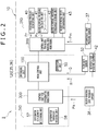
- FIG. 1 is a systematic diagram of an extracorporeal circulation device 1 according to the embodiment of the present invention. Note that a diagram surrounded by a one-dot-chain line is an enlarged view around an interlock tube 3 that couples a centrifugal pump 4 and an oxygenator 2.
- the extracorporeal circulation device 1 of this diagram has a blood circuit (referred to also as “blood circulation circuit") 1 R including conduits of blood with which blood is removed from a vein of a patient (subject) P and thereafter this blood is returned to an artery of the patient again.
- blood circulation circuit a blood circuit including conduits of blood with which blood is removed from a vein of a patient (subject) P and thereafter this blood is returned to an artery of the patient again.
- the blood circuit 1 R is configured from blood removal to return to the inside of the body of the patient P in order of a blood-removal-side cannula 5, a blood removal line (blood removal tube) 11, the centrifugal pump 4 that sends blood, the oxygenator 2 that carries out gas exchange operation for the blood, a blood sending line (blood sending tube) 12, and a blood-sending-side cannula 6.
- the blood circuit 1 R substitutes for the heart and the lung.
- the blood-removal-side cannula 5 is inserted in a vein of the patient P and is joined to the blood removal line 11 by a connector CN. Furthermore, the blood-sending-side cannula 6 is inserted in an artery of the patient P and is joined to the blood sending line 12 by a connector CM.
- the blood removal line 11 and the blood sending line 12 are conduits outside the body, and tubes made of a synthetic resin having high transparency, such as a vinyl chloride resin or silicone rubber, can be used for example.
- a synthetic resin having high transparency such as a vinyl chloride resin or silicone rubber
- the centrifugal pump 4 is connected to the downstream-side end part of the blood removal line 11, and withdraws blood from the vein of the patient P to remove the blood through the blood removal tube 11 when being actuated based on a command from a controller 10. Then, the removed blood can be sent to the artery of the patient P through the blood sending tube 12 after passing through the oxygenator 2.
- the centrifugal pump 4 is composed of a pump head 4b having a rotor (not shown) in which a magnet is embedded and a drive motor (drive source) 4a to which a magnet is attached on the side of this pump head 4b.
- the drive motor 4a rotates
- the rotor rotates by a magnetic force.
- blood that flows into the pump from an inflow port 15 existing at the central part of the pump is discharged from an outflow port 16 formed in the outer circumferential surface by a centrifugal force.
- the rotation speed of the drive motor 4a is set by an operation unit 50 formed of a rotary knob or the like of the controller 10 and is capable of rotation at 1000 to 5000 rpm for example (in the case of the present embodiment, at most 3000 rpm).
- the centrifugal pump 4 of the present embodiment has rotation speed measuring equipment 42 such as an optical rotary encoder for example in the chassis of the drive motor 4a and rotation speed R of the drive motor 4a is detected.
- This detected rotation speed R is converted to an electrical signal and is transmitted to the controller 10, which enables the rotation speed of the centrifugal pump 4 to be determined in real time.
- a publicly-known temperature sensor (not shown) is provided in the chassis of the pump head 4b and the detection result of this temperature sensor is transmitted to the controller 10, which enables measurement of the blood temperature.
- current change of the drive motor 4a is also transmitted to the controller 10 and thereby the controller 10 calculates the blood viscosity and measures the hematocrit value (for example, refer to Japanese Patent Laid-open No. 1999-76394 ).
- the measurement means for the rotation speed R of the centrifugal pump 4, the blood temperature, and the hematocrit value are not limited to the above-described aspect and it is also possible to use another publicly-known means.
- a barcode BC for identification of the kind the centrifugal pump 4 is displayed on the centrifugal pump 4.
- This barcode BC is read by a barcode reader 81 connected to the controller 10, which enables identification of the kind of the centrifugal pump 4 used.
- the oxygenator 2 is a publicly-known membrane oxygenator disposed between the centrifugal pump 4 and the blood sending tube 12, and preferably a hollow fiber oxygenator and more preferably an oxygenator of the external reflux type is used.
- the oxygenator 2 of the present embodiment is supplied with a mixed gas in which the oxygen concentration is adjusted from a gas port 78 through a tube 14.
- the mixed gas that has entered from this gas port 78 passes in plural hollow fibers (gas exchange membranes of the hollow fiber type) obtained by setting porous membranes to a straw shape.
- the blood that flows from the centrifugal pump 4 is introduced into the oxygenator 2 from a blood inflow port 79 different from the gas port 78.
- the blood that has entered from this blood inflow port 79 passes among the plural hollow fibers and is sent from an outflow port 53 to the blood sending line 12. Then, gas exchange is carried out between the inside and outside of the hollow fibers.
- a barcode BC for identification of the kind is displayed on the oxygenator 2 similarly to the centrifugal pump 4 and is read by the barcode reader 81, which enables identification of the kind.
- oxygenator 2 of the present invention is not limited to such an external reflux type and may be an internal reflux type or may be a membrane oxygenator different from the hollow fiber type.
- a blood-sending-side pressure sensor 38 that detects the pressure of the inside of the blood sending line 12 and a flow rate sensor 52 that detects the flow rate of the blood in the blood sending line 12 are disposed.
- the detection results of the blood-sending-side pressure sensor 38 and the flow rate sensor 52 are converted to an electrical signal and are transmitted to the controller 10.
- the blood-sending-side pressure sensor 38 it is preferable for the blood-sending-side pressure sensor 38 to be disposed close to the outflow port 53 of the oxygenator 2, and the blood-sending-side pressure sensor 38 has a function of detecting the pressure as immediately after outflow from the oxygenator 2 as possible and measuring a post-oxygenator pressure to be described later.
- a publicly-known pressure meter can be used as the blood-sending-side pressure sensor 38.
- a pressure meter in which a pressure-sensitive element detects the displacement of a diaphragm due to the pressure and the displacement is converted to an electrical signal can be used.
- the flow rate sensor 52 allows grasping of the flow rate of blood that flows in the blood circuit 1 R and has a function of calculating the discharge pressure specific to the centrifugal pump 4, and so forth, as described later.
- a known flowmeter can be used as the flow rate sensor 52.
- a sensor of an ultrasonic propagation time difference system is used. This sensor of the ultrasonic propagation time difference system transmits and receives ultrasonic waves regarding both of the bloodstream direction W and the opposite direction thereof and detects the blood flow rate from the difference in the transmission time of the ultrasonic waves based on these directions.
- the flow rate sensor 52 in FIG. 1 is disposed separately from the blood-sending-side pressure sensor 38 and is disposed downstream relative to the blood-sending-side pressure sensor 38.
- the blood-sending-side pressure sensor 38 and the flow rate sensor 52 disposed on the blood sending line 12 in the present invention are not limited to such an aspect.
- One detector may double as a blood-sending-side pressure sensor and a flow rate sensor and the pressure and the blood flow rate in the blood sending line 12 may be measured at one place.
- the extracorporeal circulation device 1 of the present embodiment has an intermediate part pressure sensor 37 that is a pressure sensor that detects the pressure in the circuit between the centrifugal pump 4 and the oxygenator 2.
- This intermediate part pressure sensor 37 has two functions in combination mainly. Although details will be described later, one is a function for estimating the pressure in the blood removal line 11 and the other is a function for determining the replacement timing of the oxygenator 2.
- the sensor itself is a publicly-known sensor and may be the same as or different from the blood-sending-side pressure sensor 38.
- a publicly-known method can also be used as the method for attaching the intermediate part pressure sensor 37 to the interlock tube 3 between the centrifugal pump 4 and the oxygenator 2.
- the intermediate part pressure sensor 37 is directly or indirectly connected to a connector of a three-way stopcock 8 connected to the interlock tube 3.
- the interlock tube 3 is formed to be short compared with at least the tubes of the blood removal line 11 and the blood sending line 12 so that the pressure loss between the centrifugal pump 4 and the oxygenator 2 may be as small as possible.
- the interlock tube 3 passes in a guard member 17 that guards the periphery of the interlock tube 3.
- the guard member 17 engages with both end parts of the interlock tube 3 while keeping the interlock tube 3 straight. This prevents bending and so forth of the interlock tube 3.
- the intermediate part pressure sensor 37 in the diagram, the three-way stopcock 8 for connecting to the interlock tube 3) is connected adjacent to the interlock tube 3 in this guard member 17, more preferably close to the centrifugal pump 4.
- the centrifugal pump 4, the blood-sending-side pressure sensor 38, the flow rate sensor 52, and the intermediate part pressure sensor 37 like the above ones are connected to the controller 10 and transmission and reception of signals are carried out between these components and the controller 10.
- the controller 10 is a dedicated computer composed of a central processing unit (CPU), a read only memory (ROM), a random access memory (RAM), and so forth that are connected to each other via a bus, which is not diagrammatically represented, and are configured to operate on the basis of a clock signal of a clock transmitter.
- the controller 10 may be a computer having general versatility.
- the controller 10 has a main control unit 100 that carries out determination and control of the overall operation, a control unit 200 for blood-removal-side monitoring that mainly carries out determination and control relating to the blood removal line 11, and a control unit 300 for oxygenator monitoring that mainly carries out determination and control relating to the oxygenator.
- the control unit of the present invention is not limited to such a configuration.
- the control unit 200 for blood-removal-side monitoring and the control unit 300 for oxygenator monitoring may be combined into the main control unit 100 and be united, and operation and control of the device may be carried out in accordance with a predetermined procedure.
- the operation unit 50 formed of a rotary knob or the like is connected to the main control unit 100 and a signal based on operation of this operation unit 50 is distributed to the respective units. For example, this signal is transmitted to the drive motor 4a connected to the main control unit 100, which enables the rotation speed of the centrifugal pump 4 to be set by the operation of the operation unit 50.
- the rotation speed measuring equipment 42, the flow rate sensor 52, the control unit 200 for blood-removal-side monitoring, and the control unit 300 for oxygenator monitoring are connected to the main control unit 100, and the detection results of the rotation speed measuring equipment 42 and the flow rate sensor 52 are distribution-transmitted to the control unit 200 for blood-removal-side monitoring and the control unit 300 for oxygenator monitoring as signals in accordance with a predetermined procedure.
- an informing unit 120 composed of an alarm 36 such as a buzzer or a speaker and a display screen 35 such as a liquid crystal screen is connected to the main control unit 100. Based on signals received from the respective control units 200 and 300, the flow rate sensor 52, and so forth, the informing unit 120 can inform the contents of the signals.
- the alarm 36 is configured to make warning or the like for informing an abnormality in the pressure value of the blood removal line 11 or informing the replacement timing of the oxygenator 2 as described later.
- the control unit 200 for blood-removal-side monitoring is a control unit for mainly determining the pressure in the blood removal line 11 and monitoring the blood removal state based on the intermediate part pressure sensor 37 electrically connected to the control unit 200 and the respective circuits or programs although a pressure sensor is not attached to the blood removal line 11.
- the determination and control method for monitoring this blood removal state will be described in detail with reference to FIG. 2 and subsequent drawings.
- control unit 300 for oxygenator monitoring is a control unit for estimating the pressure loss in the oxygenator 2 by subtracting a pressure value Pm measured in the intermediate part pressure sensor 37 (pressure value of the upstream side relative to the oxygenator 2) from a pressure value Pa measured in the blood-sending-side pressure sensor 38 (pressure value of the downstream side relative to the oxygenator 2) and determining the replacement timing of the oxygenator 2 based on this pressure loss.
- Pm pressure value measured in the intermediate part pressure sensor 37
- Pa pressure value of the blood-sending-side pressure sensor 38
- FIG. 2 is a schematic block diagram showing the characteristic configuration of the extracorporeal circulation device 1.
- FIG. 3 is a schematic block diagram showing the main configuration of a discharge pressure identifying unit 40 in FIG. 2 .
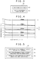
- FIG. 4 is performance data showing the correlation among the discharge pressure, the blood flow rate, and the rotation speed regarding the centrifugal pump.
- FIG. 5 is a schematic block diagram showing the main configuration of a blood removal state determining unit 43 in FIG. 2 .
- FIG. 6 is performance data showing the correlation between the blood flow rate and the pressure loss regarding the oxygenator.
- FIG. 7 is a schematic block diagram showing the main configuration of an oxygenator threshold deciding unit 58 in FIG. 2 .
- the extracorporeal circulation device 1 has, in the controller 10, a "module 210 for the blood removal line” and a “module 310 for the oxygenator” that are obtained by modularizing the above-described main control unit 100 and programs.
- the module 210 for the blood removal line has the control unit 200 for blood-removal-side monitoring that carries out operation and control of the whole of this module and the "discharge pressure identifying unit 40," a “blood removal pressure calculating unit 41,” a “blood removal pressure threshold storing unit 42,” and the “blood removal state determining unit 43" by which data is transferred and received between these units and this control unit 200 for blood-removal-side monitoring.
- the "discharge pressure identifying unit 40" is a program for identifying the discharge pressure specific to the centrifugal pump (discharge pressure value corresponding to performance data specific to the centrifugal pump used) based on the rotation speed R of the centrifugal pump and a blood flow rate Q detected in the flow rate sensor.
- the discharge pressure identifying unit 40 has a "pump performance data table 60" and a “pump discharge pressure figuring-out unit 62" in which a program for figuring out the aforesaid specific discharge pressure is stored.
- the pump performance data table 60 is a data table based on the specific correlation of "rotation speed - blood flow rate - discharge pressure" defined corresponding to each kind of centrifugal pump.
- a data table corresponding to plural kinds of centrifugal pumps is stored.
- a data table created based on the correlation of "rotation speed (rpm) - blood flow rate (L/minute) - discharge pressure (mmHg)" shown in FIG. 4 is stored.
- the correlation of FIG. 4 is one specific to "CAPIOX (trade name) centrifugal pump: made by Terumo Corporation.”
- the control unit 200 for blood-removal-side monitoring shown in FIG. 2 acquires data of the "rotation speed R" in the aforesaid correlation from the rotation speed measuring equipment 42 through the main control unit 100 and acquires data of the "blood flow rate Q" from the flow rate sensor 52 through the main control unit 100.
- the discharge pressure Pr figured out from only the relationship between the rotation speed R and the blood flow rate Q is a numerical value corresponding to the predefined performance data specific to the centrifugal pump used and does not correspond to environmental change. For this reason, there is a possibility that the actual discharge pressure may vary from the estimated discharge pressure Pr.
- the hematocrit value and the blood temperature are causes of the numerical value variation. Therefore, it is preferable to take account of the hematocrit value and the blood temperature and correct the numerical value of the estimated discharge pressure Pr. For example, if FIG.
- FIG. 4 is a correlation diagram of the case in which the hematocrit value is 35 ⁇ 1% and the blood temperature is 37 ⁇ 1°C, when the hematocrit value becomes higher than this value or the blood temperature becomes lower, the viscosity of the blood becomes higher and the discharge pressure becomes higher even with the same rotation speed and flow rate as shown by one-dot-chain lines in FIG. 4 for example. Therefore, it is preferable to correct the discharge pressure. This can estimate the discharge pressure with higher accuracy.
- the "blood removal pressure calculating unit 41" in FIG. 2 is a unit for estimating the magnitude of the pressure in the blood removal line 11 in FIG. 1 and specifically is a program that subtracts the discharge pressure Pr identified in the discharge pressure identifying unit 40 in FIG. 2 from the pressure Pm measured by the intermediate part pressure sensor 37 (Pm - Pr). Specifically, the intermediate part pressure sensor 37 in FIG. 1 actually measures the pressure in the interlock tube 3 immediately subsequent to (immediately downstream of) the centrifugal pump 4. This immediately-subsequent pressure is the pressure obtained by adding the discharge pressure of the centrifugal pump 4 to the pressure in the blood removal line 11 attributed to bloodstream from the vein of the patient P. Therefore, as shown in FIG.
- an estimated pressure value Pv in the blood removal line (hereinafter, referred to as "estimated blood removal pressure") can be obtained by subtracting the discharge pressure Pr of the centrifugal pump (discharge pressure identified in the discharge pressure identifying unit 40) from the pressure Pm actually measured in the intermediate part pressure sensor 37.
- the "blood removal pressure threshold storing unit 42" in FIG. 2 is a determination criterion unit that stores a threshold necessary for determining whether or not the estimated blood removal pressure Pv corresponds to a failure of the blood removal function. Note that because normally the inside of the blood removal line is in a negative pressure state, a negative numerical value such as -100 mmHg for example is set as the threshold. This threshold differs depending on the sex, age, and condition of the patient and therefore it is preferable that the threshold be set by a user. In the present embodiment, the threshold is stored in the blood removal pressure threshold storing unit 42 via the main control unit 100 and the control unit 200 for blood-removal-side monitoring by operation of the operation unit 50.
- the "blood removal state determining unit 43" in FIG. 2 is a program that determines whether or not the estimated blood removal pressure Pv by the blood removal pressure calculating unit 41 has surpassed the required threshold stored by the blood removal pressure threshold storing unit 42 or whether or not the estimated blood removal pressure Pv has fallen below the threshold (in the case of the present embodiment, whether or not the estimated blood removal pressure Pv has gotten beyond the threshold in such a manner as to fall below the threshold). If the estimated blood removal pressure Pv falls below the threshold, the lowering of the amount of blood of the subject, improper insertion of the cannula, or the like, which becomes a cause of blood removal failure, is envisaged for example.
- the blood removal state determining unit 43 has a blood removal state determining unit main body 70 as shown in FIG. 5 and the determination is made based on a program (estimated blood removal pressure Pv ⁇ threshold) of this main body 70. Note that in the concept of the program of the blood removal state determining unit 43, a concept that the estimated blood removal pressure Pv is multiplied by a minus and whether or not the resulting value has surpassed the threshold is determined is also included.
- the blood removal state determining unit 43 has a setting clock time storing unit 74 for storing clock times at which the rotation speed of the centrifugal pump is set (initial setting and change setting). Specifically, if the rotation speed of the centrifugal pump is set by the operation unit 50 shown in FIG. 2 , the main control unit 100 outputs the clock time at which the rotation speed is set (hereinafter, referred to as "setting clock time") to the blood removal state determining unit 43 through the control unit 200 for blood-removal-side monitoring and the setting clock time storing unit 74 in FIG. 5 records the setting clock time.
- a predetermined time zone from this setting clock time is a time zone in which the discharge pressure of the centrifugal pump is instable.
- the control unit 200 for blood-removal-side monitoring in FIG. 2 does not carry out the determination of whether or not the estimated blood removal pressure Pv has fallen below the threshold based on the program of the blood removal state determining unit main body 70.
- the present invention is not limited thereto and the "required time until the discharge pressure becomes stable" may be determined by using another method. For example, preferably, if the rotation speed of the centrifugal pump is initially set, the time until the rotation speed detected in the rotation speed measuring equipment 42 rises from 0 to the set rotation speed (rotation speed set by the user with the operation unit) is regarded as the "required time until the discharge pressure of the centrifugal pump becomes stable.”
- the blood removal state determining unit 43 has a stable time determining unit 72.
- the stable time determining unit 72 is a program for operating in a predetermined time in which the discharge pressure of the centrifugal pump should be stable (i.e. after the elapse of n seconds from recording of the setting clock time by the setting clock time storing unit 74) and determining whether or not the determination that the estimated blood removal pressure Pv has fallen below the threshold (or the value obtained by multiplying the estimated blood removal pressure Pv by a minus has surpassed the threshold) has been consecutively made based on the program of the blood removal state determining unit main body 70.
- the stable time determining unit 72 of the present invention is not limited to such a configuration and may be a program that determines whether or not the average value of the estimated blood removal pressure Pv in the predetermined time in which the discharge pressure of the centrifugal pump should be stable has fallen below the threshold.
- the module 310 for the oxygenator has the control unit 300 for oxygenator monitoring that carries out operation and control of the whole of this module and an "oxygenator replacement determining unit 57" and the “oxygenator threshold deciding unit 58" by which data is transferred and received between these units and this control unit 300 for oxygenator monitoring.
- the "oxygenator replacement determining unit 57" is a unit for determining whether or not replacement of the oxygenator 2 shown in FIG. 1 is necessary (whether or not a value with which replacement is necessary is obtained), and this determination is made by determining the pressure loss in the blood circuit across the oxygenator 2. Specifically, in the oxygenator 2, the pressure loss becomes larger as a result of clogging with a thrombus in the blood circuit thereof, the deterioration of the porous membrane, or the like due to use for a long time. Thus, the oxygenator replacement determining unit 57 checks that this pressure loss is a value surpassing a required threshold and determines the replacement timing.
- the oxygenator replacement determining unit 57 shown in FIG. 2 is a program that determines whether or not replacement of the oxygenator is necessary based on the difference between the pressure value measured in the blood-sending-side pressure sensor 38 connected to the downstream side of the oxygenator (hereinafter, referred to as "post-oxygenator pressure Pa") and the pressure value measured in the intermediate part pressure sensor 37 connected to the upstream side of the oxygenator (hereinafter, referred to as "pre-oxygenator pressure Pm").
- the numerical value based on this difference is the numerical value obtained based on "pre-oxygenator pressure Pm - post-oxygenator pressure Pa," and the pressure loss in the blood circuit in the oxygenator 2 is calculated by subtracting the post-oxygenator pressure Pa from the pre-oxygenator pressure Pm in this manner. Furthermore, if this calculated pressure loss value surpasses a threshold decided in the oxygenator threshold deciding unit 58 in FIG. 2 , a command to carry out informing is issued to the informing unit 120.
- the numerical value calculated by subtracting the "post-oxygenator pressure Pa" from the “pre-oxygenator pressure Pm” may be turned to a graph or the like and be displayed on the display screen in real time.
- the "oxygenator threshold deciding unit 58" in FIG. 2 is a unit that determines the required threshold to serve as the basis of whether or not oxygenator replacement is necessary.
- this oxygenator threshold deciding unit 58 has a specification-by-specification oxygenator performance DT 68 and a threshold determining unit 69.
- the specification-by-specification oxygenator performance DT 68 is a data table relating to a certain pressure loss (constant, hereinafter referred to as "pressure loss constant") P1 with which replacement is deemed to be necessary based on the manufacturer specifications of the oxygenator.
- pressure loss constant is approximately 300 to 500 mmHg. It suffices for this pressure loss constant to be decided in advance based on the manufacturer specifications. Furthermore, for example, the pressure loss constant may be decided based on the pressure loss measured when the oxygenator was replaced in the past (pressure loss when the oxygenator deteriorated).
- the threshold determining unit 69 decides the threshold by adding a pressure loss that is normal (hereinafter, referred to as "normal pressure loss") P2 corresponding to the blood flow rate of the oxygenator to the pressure loss constant P1 identified in the specification-by-specification oxygenator performance DT 68.
- normal pressure loss a pressure loss that is normal
- P2 a pressure loss that is normal
- P1 identified in the specification-by-specification oxygenator performance DT 68.
- the threshold is decided by adding the "normal pressure loss P2" to the "pressure loss constant P1.” This can prevent unnecessary replacement of the oxygenator and avoid the fear of imposing an extra burden on the body of the subject.
- Data of the blood flow rate for identifying the normal pressure loss P2 is distributed in real time from the main control unit 100 connected to the flow rate sensor 52 as shown in FIG. 2 . Furthermore, it is preferable that data from which the correlation between the blood flow rate and the normal pressure loss P2 is understood like that shown in FIG. 6 be prepared as a data table for each of the kinds of oxygenators stored in the specification-by-specification oxygenator performance DT 68 in FIG. 7 .
- the threshold for oxygenator replacement is decided in this manner.
- the oxygenator is "CAPIOX LX (trade name)" made by Terumo Corporation and the blood flow rate is 4 L/minute
- the normal pressure loss P2 which is not attributed to clogging or the like, is approximately 50 mmHg as shown in FIG. 6
- the threshold determining unit 69 in FIG. 7 decides 400 mmHg obtained by adding 50 mmHg (normal pressure loss P2) to 350 mmHg (pressure loss constant P1) as the threshold.
- FIG. 8 is a schematic flowchart showing characteristic operation relating to informing of the state of the blood removal side of the extracorporeal circulation device 1 of FIG. 1 .
- blood circulation is started after the power supply of the controller 10 shown in FIG. 2 is turned on and thereafter initial setting is carried out by using the operation unit 50 and so forth as preparation prior to the blood circulation.
- selection of the kinds of the oxygenator and the centrifugal pump exists.
- these kinds can be automatically input by reading the barcodes BC displayed on the oxygenator 2 and the centrifugal pump 4 shown in FIG. 1 by the barcode reader 81.
- the present invention is not limited thereto and the model numbers of the oxygenator and the centrifugal pump may be selected and input with a pull-down menu for example.
- step 1 the setting (including also change setting) of the rotation speed of the centrifugal pump is checked (step 1) and the setting clock time is recorded in the setting clock time storing unit 74 in FIG. 5 .
- the threshold relating to the pressure of the blood removal line serving as the determination criterion of blood removal failure also exists.
- the threshold is decided by the operation unit 50 in FIG. 2 according to the sex, age, and condition of the patient.
- the rotation speed of the centrifugal pump is measured in the rotation speed measuring equipment 42 in FIG. 2 (step 2 in FIG. 8 ).
- This measured numerical value is sequentially sent to the module 210 for the blood removal line in FIG. 2 and is updated and recorded in a storing unit, which is not diagrammatically represented.
- step 3 in FIG. 8 the pressure value between the centrifugal pump and the oxygenator (pressure Pm of the immediately-downstream side of the centrifugal pump) is measured in the intermediate part pressure sensor 37 in FIG. 2 (step 3 in FIG. 8 ). Note that in the present invention, the order of step 2 and step 3 in FIG. 8 may be reversed.
- the discharge pressure Pr specific to the centrifugal pump is identified (step 4 in FIG. 8 ).
- the blood flow rate Q of the blood sending line is measured in the flow rate sensor 52 in FIG. 2 and the rotation speed R of the centrifugal pump already measured in step 2 is used to identify the discharge pressure Pr of the centrifugal pump based on the correlation of "blood flow rate - rotation speed - discharge pressure" specific to the centrifugal pump used, like that shown in FIG. 4 for example.
- step 4 the discharge pressure Pr of the centrifugal pump identified in step 4 is subtracted from the pressure Pm measured in step 3 in FIG. 8 (pressure measured in the intermediate part pressure sensor) to calculate the estimated blood removal pressure Pv, and the pressure value is displayed on the display screen 35 in FIG. 1 (step 5 in FIG. 8 ).
- This operation from step 2 to step 5 is carried out at all times and the estimated blood removal pressure Pv can be displayed in real time.
- the required threshold is a threshold set in advance by the user at the time of initial setting work.
- step 6-1 If the estimated blood removal pressure Pv surpasses the required threshold in step 6 in FIG. 8 , warning is not issued (step 6-1) and the process returns to step 1, so that the operation is started from the check of setting of the rotation speed of the centrifugal pump.
- step 6-1 If it is determined that the estimated blood removal pressure Pv has fallen below the required threshold in step 6 in FIG. 8 , it is determined whether or not the required time for stabilization of the discharge pressure (n seconds) has elapsed from the setting (including also change setting) of the rotation speed of the centrifugal pump checked in step 1 (step 7). It suffices for this required time to be identified according to the characteristics of the drive motor. For example, in the case of "CAPIOX (trade name) centrifugal pump controller SP-101 (drive motor): made by Terumo Corporation," it is sufficient to set the required time to approximately 10 seconds.
- step 6-1 warning is not carried out (step 6-1) and the process returns to step 1, so that the operation is started from the check of setting of the rotation speed of the centrifugal pump.
- step 8 it is determined whether or not the estimated blood removal pressure Pv has consecutively fallen below the required threshold in a predetermined time in which the discharge pressure of the centrifugal pump should be stable (m seconds), based on the program of the stable time determining unit 72 in FIG. 5 .
- the purpose of determining whether or not the estimated blood removal pressure Pv has not surpassed the threshold consecutively for the m seconds in step 8 in FIG. 8 is to exclude warning due to pressure variation of instantaneous bending of the tube or the like. Therefore, it is preferable for these m seconds to be short compared with the n seconds until the discharge pressure of the centrifugal pump becomes stable in step 7.
- the m seconds are the number of seconds that is equal to or longer than the number of seconds with which it can be determined that the estimated blood removal pressure Pv gets beyond the threshold plural times, and is shorter than the n seconds in step 7.
- the m seconds are equal to or shorter than half the n seconds in step 7 (in the present embodiment, equal to or shorter than 5 seconds).
- step 6-1 If it is determined that the estimated blood removal pressure Pv has not consecutively fallen below the threshold as a result, warning is not carried out (step 6-1) and the process returns to step 1. On the other hand, if it is determined that the estimated blood removal pressure Pv has fallen below the required threshold consecutively for the m seconds, the process proceeds to step 9, where display of "blood removal failure" or the like is carried out and warning is issued by the alarm to inform the user of the existence of possibility of blood removal failure.
- step 8 in FIG. 8 whether or not the average value of the estimated blood removal pressure Pv in the m seconds has fallen below the threshold may be employed as the determination criterion.
- step 10 deactivation of the warning is checked (step 10). If the warning is deactivated, the work is ended. In contrast, if the warning is not deactivated in step 10, the process returns to step 1 and the monitoring of the blood removal failure is continued in a similar manner.
- FIG. 9 is a schematic flowchart showing characteristic operation relating to informing of oxygenator replacement of the extracorporeal circulation device 1 of FIG. 1 .
- the module 210 for the blood removal line shown in FIG. 2 transmits the pressure value Pm to the module 310 for the oxygenator through the main control unit 100 and the control unit 300 for oxygenator monitoring receives it (step 301 in FIG. 9 ).
- step 302 in FIG. 9 the pressure difference between before and after the oxygenator is calculated. Specifically, the pressure (pre-oxygenator pressure) Pm received in step 301 is subtracted from the pressure (post-oxygenator pressure) Pa measured in the blood-sending-side pressure sensor 38 in FIG. 2 to estimate the pressure loss in the blood circuit of the oxygenator.
- the threshold in this step 303 is a threshold decided in the threshold determining unit 69 in FIG. 7 and is the numerical value obtained by adding the normal pressure loss P2, which corresponds to the blood flow rate of the oxygenator (which is not attributed to clogging with a thrombus or the like), to the pressure loss constant P1 identified through the operation unit or barcode reading at the time of initial setting.
- step 301 if the calculated pressure loss does not surpass the required threshold, the process returns to step 301.
- the pressure loss surpasses the required threshold it is determined that replacement of the oxygenator is necessary and display of "oxygenator replacement" is carried out on the display screen 35 in FIG. 1 .
- warning is made by the alarm 36 (step 304 in FIG. 9 ).
- the warning sound at the time and the warning sound in step 8 in FIG. 8 may be the same because a check by the display screen is possible, or may be different.
- the extracorporeal circulation device that can deal with various oxygenators and centrifugal pumps is employed.
- the extracorporeal circulation device may be an extracorporeal circulation device compatible with only one kind of oxygenator and centrifugal pump decided in advance. This eliminates the need to select the kinds of oxygenator and blood pump in initial setting work.
- module 210 for the blood removal line and the module 310 for the oxygenator in FIG. 2 are configured by modularizing programs. However, they may be configured by circuits.
- the replacement of the oxygenator is necessary if the numerical value obtained by subtracting the post-oxygenator pressure Pa from the pre-oxygenator pressure Pm surpasses the required threshold in FIG. 9 .
- the replacement of the oxygenator is necessary if the ratio between the pre-oxygenator pressure Pm and the post-oxygenator pressure Pa surpasses the required threshold.
- the module 310 for the oxygenator and the blood-sending-side pressure sensor 38 which are shown in FIG. 2 , for determining replacement of the oxygenator and the operation example of FIG. 9 are not essential constituent elements.
Abstract
Description
- The present invention relates to an extracorporeal circulation device capable of measuring a pressure in an extracorporeal circulation circuit.
- Conventionally, in the case of performing a cardiac surgery operation of a patient or supporting the cardiopulmonary function, or the like, extracorporeal blood circulation is carried out in which a blood pump of an extracorporeal circulation device is actuated to withdraw blood through a blood removal line (blood removal tube) connected to a vein of the patient so that a gas exchange in the blood is carried out in an oxygenator disposed downstream relative to the blood pump and then this blood is returned to an artery of the patient again through a blood sending line (blood sending tube).
- Regarding such an extracorporeal circulation device in which the blood flows in order of the blood removal line, the blood pump, the oxygenator, and the blood sending line, a pressure sensor is conventionally connected to the blood removal line closer to the venous side of the patient (for example, refer to Patent Document 1). Due to this, the state of the patient can be determined more correctly. Specifically, for example, it can be envisaged that the amount of blood in the body of the patient is insufficient if the value of the pressure in the tube of the blood removal line is excessively low.
- To connect the pressure sensor to the blood removal line as above, generally a method is employed in which a three-way stopcock is connected to a tube and the pressure sensor is fitted to a connector of this three-way stopcock. Furthermore, in recent years, a device of a type in which a pressure sensor is connected built into a tube in advance as in
Patent Document 2 has also existed. -
- Patent Document 1: Japanese Patent Laid-open No.
2013-192712 - Patent Document 2: Japanese Patent Laid-open No.
2014-68739 - Because the blood removal line is disposed on the upstream side of the blood pump, a negative pressure state is made in the tube. For this reason, in the case of connecting a pressure sensor by using a three-way stopcock, there is a possibility that air could be drawn into the tube, resulting in generation of an air bubble if the connection to the three-way stopcock is loose or a user forgets to close the stopcock when removing the pressure sensor.
- Note that with the device of the type in which a pressure sensor is connected to a tube in advance, the structure is complicated and the manufacturing cost is high although the risk of drawing of air is low. In addition, there is also a problem that sterilization is difficult.
- The present invention provides an extracorporeal circulation device in which the risk of generation of an air bubble is alleviated and the state of a patient is also easily determined.
- The aforesaid problems are solved by an extracorporeal circulation device including a blood removal line through which blood withdrawn from a body of a subject is conveyed, a centrifugal pump that is connected downstream of the blood removal line and carries out blood sending by rotational motion, an oxygenator connected downstream relative to the centrifugal pump, a blood return line that is downstream relative to the oxygenator and returns blood to the inside of the body, and a flow rate sensor that detects a blood flow rate in the blood return line, the extracorporeal circulation device includs an intermediate part pressure sensor that detects pressure in a circuit between the centrifugal pump and the oxygenator, and a discharge pressure identifying unit that identifies discharge pressure specific to the centrifugal pump based on the rotation speed of the centrifugal pump and the blood flow rate detected in the flow rate sensor.
- In the configuration of the aforesaid present invention, the pressure sensor for measuring the pressure in the circuit is disposed not on the blood removal line, which becomes a negative pressure state, but between the centrifugal pump and the oxygenator, i.e. in the circuit that is immediately downstream of the centrifugal pump and is in a high positive pressure state. For this reason, even when the pressure sensor is connected by a three-way stopcock, the fear of drawing of an air bubble from the position of the three-way stopcock is low. Therefore, air can be effectively prevented from entering the inside of the circulation circuit.
- Furthermore, a tube is short between the centrifugal pump and the oxygenator and thus pressure change resulting from the deformation of the tube is also small. Therefore, fluctuation in the pressure value measured in the intermediate part pressure sensor is also small and the user also is unlikely to be forced to make an unnecessary determination.
- In addition, when the pressure sensor is provided between the centrifugal pump and the oxygenator so that pressure is measured downstream of the oxygenator, the pressure loss in the oxygenator can be estimated through subtraction of the pre-oxygenator pressure from the post-oxygenator pressure. Due to this, it is also possible to grasp the deterioration of the oxygenator and so forth.
- Moreover, in the configuration of the aforesaid present invention, the extracorporeal circulation device has the discharge pressure identifying unit that identifies the discharge pressure specific to the centrifugal pump based on the rotation speed of the centrifugal pump and the blood flow rate detected in the flow rate sensor in the blood sending line. For this reason, it can be detected that the state of the patient is abnormal whenever the pressure measured in the intermediate part pressure sensor (pressure sensor existing immediately subsequent to the centrifugal pump) is an abnormal numerical value that is inconsistent with the expected discharge pressure specific to the centrifugal pump used (for example, if the pressure measured in the intermediate part pressure sensor is lower than even 300 mmHg although the discharge pressure specific to the centrifugal pump is 600 mmHg when operating at the set rotation speed of the centrifugal pump, then the pressure from the venous side of the patient is too low and thus it can be concluded that the amount of blood in the body of the patient is too small).
- Furthermore, and most preferably, the extracorporeal circulation device is characterized by including a blood removal pressure calculating unit that subtracts the discharge pressure identified in the discharge pressure identifying unit from the pressure measured by the intermediate part pressure sensor to estimate pressure in the blood removal line.
- Therefore, the pressure in the tube in the blood removal line is estimated, which makes it easier to automatically detect the blood removal state of the patient. That is, it can be predicted that the pressure obtained by subtracting the specific discharge pressure value (as identified in the discharge pressure identifying unit) from the pressure measured by the intermediate part pressure sensor is not less than the actual pressure in the blood removal line(regardless of the discharge pressure of the centrifugal pump). Therefore, although a pressure sensor is not provided in the blood removal line, the pressure in the blood removal line can be reliably obtained.
- Moreover, preferably, the extracorporeal circulation device is characterized by including a blood removal state determining unit that determines whether or not the pressure calculated in the blood removal pressure calculating unit has surpassed a threshold composed of a value necessary for determining blood removal failure or whether or not the pressure calculated in the blood removal pressure calculating unit has fallen below the threshold, and informing means that indicates whether the blood removal state determining unit has determined that the pressure calculated in the blood removal pressure calculating unit has surpassed or fallen below the threshold. Therefore, the user can determine blood removal failure by the informing of the informing means and examine reasons for the lowering of the amount of blood of the subject, such as improper insertion of a cannula, or the like.
- Furthermore, preferably, the extracorporeal circulation device is characterized in that the blood removal state determining unit does not carry out the determination in a required time until the discharge pressure of the centrifugal pump becomes stable after the rotation speed of the centrifugal pump is set. Therefore, even if the discharge pressure of the centrifugal pump is briefly unstable after the rotation speed of the centrifugal pump is set through starting actuation of the centrifugal pump or changing the rotation speed in the middle and thus the pressure value calculated in the blood removal pressure calculating unit falls below the required threshold for example, the situation in which this is informed needlessly can be prevented.
- Moreover, preferably, the extracorporeal circulation device is characterized in that the blood removal state determining unit determines whether or not an average value of the pressure calculated in the blood removal pressure calculating unit has surpassed the threshold or whether or not the average value has fallen below the threshold, or determines whether or not the pressure calculated in the blood removal pressure calculating unit has consecutively surpassed the threshold or whether or not the pressure calculated in the blood removal pressure calculating unit has consecutively fallen below the threshold.
- Therefore, even if the case in which the pressure calculated in the blood removal pressure calculating unit falls below the required threshold instantaneously exists in a time period in which the discharge pressure of the centrifugal pump should be stable, the situation in which this is informed needlessly can be effectively prevented.
- Furthermore, preferably, the extracorporeal circulation device is characterized in that the discharge pressure is identified while taking account of a hematocrit value and/or a blood temperature. Thus, the blood removal pressure calculating unit can estimate the pressure in the blood removal line with higher accuracy because it accounts for the fact that the hematocrit value and the blood temperature change the viscosity of the blood, which affects the discharge pressure.
- As above, according to the present invention, an extracorporeal circulation device with which the risk of generation of an air bubble is alleviated and the state of a patient is also easily determined can be provided.
-
- [
FIG. 1 ]
FIG. 1 is a systematic diagram showing a preferred embodiment of an extracorporeal circulation device of the present invention. - [
FIG. 2 ]
FIG. 2 is a schematic block configuration diagram showing the characteristic configuration of the extracorporeal circulation device ofFIG. 1 . - [
FIG. 3 ]
FIG. 3 is a schematic block diagram showing the main configuration of a discharge pressure identifying unit inFIG. 2 . - [
FIG. 4 ]
FIG. 4 is performance data showing the correlation among the discharge pressure, the blood flow rate, and the rotation speed regarding a centrifugal pump. - [
FIG. 5 ]
FIG. 5 is a schematic block diagram showing the main configuration of a blood removal state determining unit inFIG. 2 . - [
FIG. 6 ]
FIG. 6 is performance data showing the correlation between the blood flow rate and the pressure loss regarding an oxygenator. - [
FIG. 7 ]
FIG. 7 is a schematic block diagram showing the main configuration of an oxygenator threshold deciding unit inFIG. 2 . - [
FIG. 8 ]
FIG. 8 is a schematic flowchart showing characteristic operation relating to informing of the state of the blood removal side of the extracorporeal circulation device ofFIG. 1 . - [
FIG. 9 ]
FIG. 9 is a schematic flowchart showing characteristic operation relating to informing of oxygenator replacement of the extracorporeal circulation device ofFIG. 1 . - A preferred embodiment of the present invention will be described in detail below with reference to the drawings.
- The embodiment to be described below is a preferred concrete example of the present invention and therefore is given various qualifications that are technically preferable. However, the scope of the present invention is not limited to these aspects unless there is a particular description of limiting the present invention in the following explanation. Furthermore, in the following drawings, a place given the same symbol has the same configuration unless there is particular reference.
- An extracorporeal circulation device of the present embodiment is used in the case of "auxiliary circulation operation" and "extracorporeal circulation operation" for example. The "extracorporeal circulation operation" is carrying out circulation operation of blood and gas exchange operation (oxygen addition and/or carbon dioxide removal) for this blood by the extracorporeal circulation device in the case in which the blood circulation in the heart is temporarily stopped due to a surgery operation for example. The "auxiliary circulation operation" is carrying out support of circulation operation of blood by the extracorporeal circulation device in the case in which the heart of a patient cannot fulfill the sufficient function or in the state in which gas exchange by the lung cannot be sufficiently carried out. Some devices have a function of carrying out gas exchange operation for blood.
-
FIG. 1 is a systematic diagram of anextracorporeal circulation device 1 according to the embodiment of the present invention. Note that a diagram surrounded by a one-dot-chain line is an enlarged view around aninterlock tube 3 that couples acentrifugal pump 4 and anoxygenator 2. - The
extracorporeal circulation device 1 of this diagram has a blood circuit (referred to also as "blood circulation circuit") 1 R including conduits of blood with which blood is removed from a vein of a patient (subject) P and thereafter this blood is returned to an artery of the patient again. - The
blood circuit 1 R is configured from blood removal to return to the inside of the body of the patient P in order of a blood-removal-side cannula 5, a blood removal line (blood removal tube) 11, thecentrifugal pump 4 that sends blood, theoxygenator 2 that carries out gas exchange operation for the blood, a blood sending line (blood sending tube) 12, and a blood-sending-side cannula 6. Theblood circuit 1 R substitutes for the heart and the lung. - The blood-removal-
side cannula 5 is inserted in a vein of the patient P and is joined to theblood removal line 11 by a connector CN. Furthermore, the blood-sending-side cannula 6 is inserted in an artery of the patient P and is joined to theblood sending line 12 by a connector CM. - The
blood removal line 11 and theblood sending line 12 are conduits outside the body, and tubes made of a synthetic resin having high transparency, such as a vinyl chloride resin or silicone rubber, can be used for example. In theblood removal line 11, blood flows in a V-direction (toward the centrifugal pump 4). In theblood sending line 12, blood flows in a W-direction (toward the patient P). - The
centrifugal pump 4 is connected to the downstream-side end part of theblood removal line 11, and withdraws blood from the vein of the patient P to remove the blood through theblood removal tube 11 when being actuated based on a command from acontroller 10. Then, the removed blood can be sent to the artery of the patient P through theblood sending tube 12 after passing through theoxygenator 2. - For example, the
centrifugal pump 4 is composed of apump head 4b having a rotor (not shown) in which a magnet is embedded and a drive motor (drive source) 4a to which a magnet is attached on the side of thispump head 4b. When thedrive motor 4a rotates, the rotor rotates by a magnetic force. When the rotor rotates, blood that flows into the pump from aninflow port 15 existing at the central part of the pump is discharged from anoutflow port 16 formed in the outer circumferential surface by a centrifugal force. The rotation speed of thedrive motor 4a is set by anoperation unit 50 formed of a rotary knob or the like of thecontroller 10 and is capable of rotation at 1000 to 5000 rpm for example (in the case of the present embodiment, at most 3000 rpm). - The
centrifugal pump 4 of the present embodiment has rotationspeed measuring equipment 42 such as an optical rotary encoder for example in the chassis of thedrive motor 4a and rotation speed R of thedrive motor 4a is detected. This detected rotation speed R is converted to an electrical signal and is transmitted to thecontroller 10, which enables the rotation speed of thecentrifugal pump 4 to be determined in real time. - Furthermore, a publicly-known temperature sensor (not shown) is provided in the chassis of the
pump head 4b and the detection result of this temperature sensor is transmitted to thecontroller 10, which enables measurement of the blood temperature. Moreover, current change of thedrive motor 4a is also transmitted to thecontroller 10 and thereby thecontroller 10 calculates the blood viscosity and measures the hematocrit value (for example, refer to Japanese Patent Laid-open No.1999-76394 centrifugal pump 4, the blood temperature, and the hematocrit value are not limited to the above-described aspect and it is also possible to use another publicly-known means. - In addition, on the
centrifugal pump 4, a barcode BC for identification of the kind thecentrifugal pump 4 is displayed. This barcode BC is read by abarcode reader 81 connected to thecontroller 10, which enables identification of the kind of thecentrifugal pump 4 used. - The
oxygenator 2 is a publicly-known membrane oxygenator disposed between thecentrifugal pump 4 and theblood sending tube 12, and preferably a hollow fiber oxygenator and more preferably an oxygenator of the external reflux type is used. Specifically, theoxygenator 2 of the present embodiment is supplied with a mixed gas in which the oxygen concentration is adjusted from agas port 78 through atube 14. The mixed gas that has entered from thisgas port 78 passes in plural hollow fibers (gas exchange membranes of the hollow fiber type) obtained by setting porous membranes to a straw shape. In contrast, the blood that flows from thecentrifugal pump 4 is introduced into theoxygenator 2 from ablood inflow port 79 different from thegas port 78. The blood that has entered from thisblood inflow port 79 passes among the plural hollow fibers and is sent from anoutflow port 53 to theblood sending line 12. Then, gas exchange is carried out between the inside and outside of the hollow fibers. - Furthermore, a barcode BC for identification of the kind is displayed on the
oxygenator 2 similarly to thecentrifugal pump 4 and is read by thebarcode reader 81, which enables identification of the kind. - Note that the
oxygenator 2 of the present invention is not limited to such an external reflux type and may be an internal reflux type or may be a membrane oxygenator different from the hollow fiber type. - Here, in the middle of the
blood sending line 12 downstream relative to theoxygenator 2, a blood-sending-side pressure sensor 38 that detects the pressure of the inside of theblood sending line 12 and aflow rate sensor 52 that detects the flow rate of the blood in theblood sending line 12 are disposed. The detection results of the blood-sending-side pressure sensor 38 and theflow rate sensor 52 are converted to an electrical signal and are transmitted to thecontroller 10. - It is preferable for the blood-sending-
side pressure sensor 38 to be disposed close to theoutflow port 53 of theoxygenator 2, and the blood-sending-side pressure sensor 38 has a function of detecting the pressure as immediately after outflow from theoxygenator 2 as possible and measuring a post-oxygenator pressure to be described later. A publicly-known pressure meter can be used as the blood-sending-side pressure sensor 38. To cite one example, a pressure meter in which a pressure-sensitive element detects the displacement of a diaphragm due to the pressure and the displacement is converted to an electrical signal can be used. - The
flow rate sensor 52 allows grasping of the flow rate of blood that flows in theblood circuit 1 R and has a function of calculating the discharge pressure specific to thecentrifugal pump 4, and so forth, as described later. - A known flowmeter can be used as the
flow rate sensor 52. In the case of the present embodiment, a sensor of an ultrasonic propagation time difference system is used. This sensor of the ultrasonic propagation time difference system transmits and receives ultrasonic waves regarding both of the bloodstream direction W and the opposite direction thereof and detects the blood flow rate from the difference in the transmission time of the ultrasonic waves based on these directions. - The
flow rate sensor 52 inFIG. 1 is disposed separately from the blood-sending-side pressure sensor 38 and is disposed downstream relative to the blood-sending-side pressure sensor 38. The blood-sending-side pressure sensor 38 and theflow rate sensor 52 disposed on theblood sending line 12 in the present invention are not limited to such an aspect. One detector may double as a blood-sending-side pressure sensor and a flow rate sensor and the pressure and the blood flow rate in theblood sending line 12 may be measured at one place. - Moreover, the
extracorporeal circulation device 1 of the present embodiment has an intermediatepart pressure sensor 37 that is a pressure sensor that detects the pressure in the circuit between thecentrifugal pump 4 and theoxygenator 2. This intermediatepart pressure sensor 37 has two functions in combination mainly. Although details will be described later, one is a function for estimating the pressure in theblood removal line 11 and the other is a function for determining the replacement timing of theoxygenator 2. - Regarding the intermediate
part pressure sensor 37, the sensor itself is a publicly-known sensor and may be the same as or different from the blood-sending-side pressure sensor 38. Furthermore, a publicly-known method can also be used as the method for attaching the intermediatepart pressure sensor 37 to theinterlock tube 3 between thecentrifugal pump 4 and theoxygenator 2. In the present embodiment, as one example of the method, the intermediatepart pressure sensor 37 is directly or indirectly connected to a connector of a three-way stopcock 8 connected to theinterlock tube 3. - Note that the
interlock tube 3 is formed to be short compared with at least the tubes of theblood removal line 11 and theblood sending line 12 so that the pressure loss between thecentrifugal pump 4 and theoxygenator 2 may be as small as possible. Preferably, as in the diagram shown by the one-dot-chain line, theinterlock tube 3 passes in aguard member 17 that guards the periphery of theinterlock tube 3. Theguard member 17 engages with both end parts of theinterlock tube 3 while keeping theinterlock tube 3 straight. This prevents bending and so forth of theinterlock tube 3. Furthermore, the intermediate part pressure sensor 37 (in the diagram, the three-way stopcock 8 for connecting to the interlock tube 3) is connected adjacent to theinterlock tube 3 in thisguard member 17, more preferably close to thecentrifugal pump 4. - The
centrifugal pump 4, the blood-sending-side pressure sensor 38, theflow rate sensor 52, and the intermediatepart pressure sensor 37 like the above ones are connected to thecontroller 10 and transmission and reception of signals are carried out between these components and thecontroller 10. - The
controller 10 is a dedicated computer composed of a central processing unit (CPU), a read only memory (ROM), a random access memory (RAM), and so forth that are connected to each other via a bus, which is not diagrammatically represented, and are configured to operate on the basis of a clock signal of a clock transmitter. However, thecontroller 10 may be a computer having general versatility. - The
controller 10 has amain control unit 100 that carries out determination and control of the overall operation, acontrol unit 200 for blood-removal-side monitoring that mainly carries out determination and control relating to theblood removal line 11, and acontrol unit 300 for oxygenator monitoring that mainly carries out determination and control relating to the oxygenator. The control unit of the present invention is not limited to such a configuration. Thecontrol unit 200 for blood-removal-side monitoring and thecontrol unit 300 for oxygenator monitoring may be combined into themain control unit 100 and be united, and operation and control of the device may be carried out in accordance with a predetermined procedure. - The
operation unit 50 formed of a rotary knob or the like is connected to themain control unit 100 and a signal based on operation of thisoperation unit 50 is distributed to the respective units. For example, this signal is transmitted to thedrive motor 4a connected to themain control unit 100, which enables the rotation speed of thecentrifugal pump 4 to be set by the operation of theoperation unit 50. - Furthermore, the rotation
speed measuring equipment 42, theflow rate sensor 52, thecontrol unit 200 for blood-removal-side monitoring, and thecontrol unit 300 for oxygenator monitoring are connected to themain control unit 100, and the detection results of the rotationspeed measuring equipment 42 and theflow rate sensor 52 are distribution-transmitted to thecontrol unit 200 for blood-removal-side monitoring and thecontrol unit 300 for oxygenator monitoring as signals in accordance with a predetermined procedure. - Furthermore, an informing
unit 120 composed of analarm 36 such as a buzzer or a speaker and adisplay screen 35 such as a liquid crystal screen is connected to themain control unit 100. Based on signals received from therespective control units flow rate sensor 52, and so forth, the informingunit 120 can inform the contents of the signals. Thealarm 36 is configured to make warning or the like for informing an abnormality in the pressure value of theblood removal line 11 or informing the replacement timing of theoxygenator 2 as described later. On thedisplay screen 35, information in setting by theoperation unit 50 and so forth (setting of the rotation speed of thecentrifugal pump 4, the kinds ofcentrifugal pump 4 andoxygenator 2, required threshold, and so forth) and various kinds of messages (blood flow rate, hematocrit value, blood temperature, values of pressure in theblood removal line 11 and theblood sending line 12, contents of an alarm, and so forth) are displayed. - The
control unit 200 for blood-removal-side monitoring is a control unit for mainly determining the pressure in theblood removal line 11 and monitoring the blood removal state based on the intermediatepart pressure sensor 37 electrically connected to thecontrol unit 200 and the respective circuits or programs although a pressure sensor is not attached to theblood removal line 11. The determination and control method for monitoring this blood removal state will be described in detail with reference toFIG. 2 and subsequent drawings. - Furthermore, the
control unit 300 for oxygenator monitoring is a control unit for estimating the pressure loss in theoxygenator 2 by subtracting a pressure value Pm measured in the intermediate part pressure sensor 37 (pressure value of the upstream side relative to the oxygenator 2) from a pressure value Pa measured in the blood-sending-side pressure sensor 38 (pressure value of the downstream side relative to the oxygenator 2) and determining the replacement timing of theoxygenator 2 based on this pressure loss. The determination and control method relating to this monitoring of theoxygenator 2 will also be described in detail with reference toFIG. 2 and subsequent drawings. - Next, the system configuration of the above-described
extracorporeal circulation device 1 will be described by reference toFIG. 2 to FIG. 7 . -
FIG. 2 is a schematic block diagram showing the characteristic configuration of theextracorporeal circulation device 1.FIG. 3 is a schematic block diagram showing the main configuration of a dischargepressure identifying unit 40 inFIG. 2 .FIG. 4 is performance data showing the correlation among the discharge pressure, the blood flow rate, and the rotation speed regarding the centrifugal pump.FIG. 5 is a schematic block diagram showing the main configuration of a blood removalstate determining unit 43 inFIG. 2 .FIG. 6 is performance data showing the correlation between the blood flow rate and the pressure loss regarding the oxygenator.FIG. 7 is a schematic block diagram showing the main configuration of an oxygenatorthreshold deciding unit 58 inFIG. 2 . - As shown in
FIG. 2 , theextracorporeal circulation device 1 has, in thecontroller 10, a "module 210 for the blood removal line" and a "module 310 for the oxygenator" that are obtained by modularizing the above-describedmain control unit 100 and programs. - First, the
module 210 for the blood removal line will be described. - The
module 210 for the blood removal line has thecontrol unit 200 for blood-removal-side monitoring that carries out operation and control of the whole of this module and the "dischargepressure identifying unit 40," a "blood removalpressure calculating unit 41," a "blood removal pressurethreshold storing unit 42," and the "blood removalstate determining unit 43" by which data is transferred and received between these units and thiscontrol unit 200 for blood-removal-side monitoring. - The "discharge
pressure identifying unit 40" is a program for identifying the discharge pressure specific to the centrifugal pump (discharge pressure value corresponding to performance data specific to the centrifugal pump used) based on the rotation speed R of the centrifugal pump and a blood flow rate Q detected in the flow rate sensor. - Specifically, as shown in
FIG. 3 , the dischargepressure identifying unit 40 has a "pump performance data table 60" and a "pump discharge pressure figuring-outunit 62" in which a program for figuring out the aforesaid specific discharge pressure is stored. - The pump performance data table 60 is a data table based on the specific correlation of "rotation speed - blood flow rate - discharge pressure" defined corresponding to each kind of centrifugal pump. In the pump performance data table 60 of the present embodiment, a data table corresponding to plural kinds of centrifugal pumps is stored. For example, a data table created based on the correlation of "rotation speed (rpm) - blood flow rate (L/minute) - discharge pressure (mmHg)" shown in
FIG. 4 is stored. Note that the correlation ofFIG. 4 is one specific to "CAPIOX (trade name) centrifugal pump: made by Terumo Corporation." - Furthermore, in order to identify a discharge pressure Pr (see
FIG. 2 ) specific to the centrifugal pump by using the pump performance data table 60, based on the program of the pump discharge pressure figuring-outunit 62, thecontrol unit 200 for blood-removal-side monitoring shown inFIG. 2 acquires data of the "rotation speed R" in the aforesaid correlation from the rotationspeed measuring equipment 42 through themain control unit 100 and acquires data of the "blood flow rate Q" from theflow rate sensor 52 through themain control unit 100. - The discharge pressure Pr figured out from only the relationship between the rotation speed R and the blood flow rate Q is a numerical value corresponding to the predefined performance data specific to the centrifugal pump used and does not correspond to environmental change. For this reason, there is a possibility that the actual discharge pressure may vary from the estimated discharge pressure Pr. The hematocrit value and the blood temperature are causes of the numerical value variation. Therefore, it is preferable to take account of the hematocrit value and the blood temperature and correct the numerical value of the estimated discharge pressure Pr. For example, if
FIG. 4 is a correlation diagram of the case in which the hematocrit value is 35 ± 1% and the blood temperature is 37 ± 1°C, when the hematocrit value becomes higher than this value or the blood temperature becomes lower, the viscosity of the blood becomes higher and the discharge pressure becomes higher even with the same rotation speed and flow rate as shown by one-dot-chain lines inFIG. 4 for example. Therefore, it is preferable to correct the discharge pressure. This can estimate the discharge pressure with higher accuracy. - The "blood removal
pressure calculating unit 41" inFIG. 2 is a unit for estimating the magnitude of the pressure in theblood removal line 11 inFIG. 1 and specifically is a program that subtracts the discharge pressure Pr identified in the dischargepressure identifying unit 40 inFIG. 2 from the pressure Pm measured by the intermediate part pressure sensor 37 (Pm - Pr). Specifically, the intermediatepart pressure sensor 37 inFIG. 1 actually measures the pressure in theinterlock tube 3 immediately subsequent to (immediately downstream of) thecentrifugal pump 4. This immediately-subsequent pressure is the pressure obtained by adding the discharge pressure of thecentrifugal pump 4 to the pressure in theblood removal line 11 attributed to bloodstream from the vein of the patient P. Therefore, as shown inFIG. 2 , an estimated pressure value Pv in the blood removal line (hereinafter, referred to as "estimated blood removal pressure") can be obtained by subtracting the discharge pressure Pr of the centrifugal pump (discharge pressure identified in the discharge pressure identifying unit 40) from the pressure Pm actually measured in the intermediatepart pressure sensor 37. - The "blood removal pressure
threshold storing unit 42" inFIG. 2 is a determination criterion unit that stores a threshold necessary for determining whether or not the estimated blood removal pressure Pv corresponds to a failure of the blood removal function. Note that because normally the inside of the blood removal line is in a negative pressure state, a negative numerical value such as -100 mmHg for example is set as the threshold. This threshold differs depending on the sex, age, and condition of the patient and therefore it is preferable that the threshold be set by a user. In the present embodiment, the threshold is stored in the blood removal pressurethreshold storing unit 42 via themain control unit 100 and thecontrol unit 200 for blood-removal-side monitoring by operation of theoperation unit 50. If at least a value obtained by subtracting approximately 50 mmHg from the present estimated blood removal pressure value Pv is employed as the threshold, it is also possible to detect an abnormal state in which the blood removal is not carried out at all due to occlusion of the tube of the blood removal line or the like. - The "blood removal
state determining unit 43" inFIG. 2 is a program that determines whether or not the estimated blood removal pressure Pv by the blood removalpressure calculating unit 41 has surpassed the required threshold stored by the blood removal pressurethreshold storing unit 42 or whether or not the estimated blood removal pressure Pv has fallen below the threshold (in the case of the present embodiment, whether or not the estimated blood removal pressure Pv has gotten beyond the threshold in such a manner as to fall below the threshold). If the estimated blood removal pressure Pv falls below the threshold, the lowering of the amount of blood of the subject, improper insertion of the cannula, or the like, which becomes a cause of blood removal failure, is envisaged for example. - Specifically, the blood removal
state determining unit 43 has a blood removal state determining unitmain body 70 as shown inFIG. 5 and the determination is made based on a program (estimated blood removal pressure Pv < threshold) of thismain body 70. Note that in the concept of the program of the blood removalstate determining unit 43, a concept that the estimated blood removal pressure Pv is multiplied by a minus and whether or not the resulting value has surpassed the threshold is determined is also included. - Furthermore, the blood removal
state determining unit 43 has a setting clocktime storing unit 74 for storing clock times at which the rotation speed of the centrifugal pump is set (initial setting and change setting). Specifically, if the rotation speed of the centrifugal pump is set by theoperation unit 50 shown inFIG. 2 , themain control unit 100 outputs the clock time at which the rotation speed is set (hereinafter, referred to as "setting clock time") to the blood removalstate determining unit 43 through thecontrol unit 200 for blood-removal-side monitoring and the setting clocktime storing unit 74 inFIG. 5 records the setting clock time. A predetermined time zone from this setting clock time is a time zone in which the discharge pressure of the centrifugal pump is instable. Furthermore, for example, when the rotation speed of the centrifugal pump is changed and set in the middle and the setting clocktime storing unit 74 records the change setting clock time at the time, for n seconds from this recording (required time until the discharge pressure of the centrifugal pump becomes stable, for 10 seconds in the case of the present embodiment), thecontrol unit 200 for blood-removal-side monitoring inFIG. 2 does not carry out the determination of whether or not the estimated blood removal pressure Pv has fallen below the threshold based on the program of the blood removal state determining unitmain body 70. - The present invention is not limited thereto and the "required time until the discharge pressure becomes stable" may be determined by using another method. For example, preferably, if the rotation speed of the centrifugal pump is initially set, the time until the rotation speed detected in the rotation
speed measuring equipment 42 rises from 0 to the set rotation speed (rotation speed set by the user with the operation unit) is regarded as the "required time until the discharge pressure of the centrifugal pump becomes stable." - Moreover, as shown in
FIG. 5 , the blood removalstate determining unit 43 has a stabletime determining unit 72. The stabletime determining unit 72 is a program for operating in a predetermined time in which the discharge pressure of the centrifugal pump should be stable (i.e. after the elapse of n seconds from recording of the setting clock time by the setting clock time storing unit 74) and determining whether or not the determination that the estimated blood removal pressure Pv has fallen below the threshold (or the value obtained by multiplying the estimated blood removal pressure Pv by a minus has surpassed the threshold) has been consecutively made based on the program of the blood removal state determining unitmain body 70. In the present embodiment, if it has been consecutively determined that the estimated blood removal pressure Pv has fallen below the threshold, this is informed by the informingunit 120 inFIG. 2 because the possibility of blood removal failure is high. The stabletime determining unit 72 of the present invention is not limited to such a configuration and may be a program that determines whether or not the average value of the estimated blood removal pressure Pv in the predetermined time in which the discharge pressure of the centrifugal pump should be stable has fallen below the threshold. - Next, the
module 310 for the oxygenator existing in thecontroller 10 inFIG. 2 will be described. - The
module 310 for the oxygenator has thecontrol unit 300 for oxygenator monitoring that carries out operation and control of the whole of this module and an "oxygenatorreplacement determining unit 57" and the "oxygenatorthreshold deciding unit 58" by which data is transferred and received between these units and thiscontrol unit 300 for oxygenator monitoring. - The "oxygenator
replacement determining unit 57" is a unit for determining whether or not replacement of theoxygenator 2 shown inFIG. 1 is necessary (whether or not a value with which replacement is necessary is obtained), and this determination is made by determining the pressure loss in the blood circuit across theoxygenator 2. Specifically, in theoxygenator 2, the pressure loss becomes larger as a result of clogging with a thrombus in the blood circuit thereof, the deterioration of the porous membrane, or the like due to use for a long time. Thus, the oxygenatorreplacement determining unit 57 checks that this pressure loss is a value surpassing a required threshold and determines the replacement timing. - The oxygenator
replacement determining unit 57 shown inFIG. 2 is a program that determines whether or not replacement of the oxygenator is necessary based on the difference between the pressure value measured in the blood-sending-side pressure sensor 38 connected to the downstream side of the oxygenator (hereinafter, referred to as "post-oxygenator pressure Pa") and the pressure value measured in the intermediatepart pressure sensor 37 connected to the upstream side of the oxygenator (hereinafter, referred to as "pre-oxygenator pressure Pm"). In the case of the present embodiment, the numerical value based on this difference is the numerical value obtained based on "pre-oxygenator pressure Pm - post-oxygenator pressure Pa," and the pressure loss in the blood circuit in theoxygenator 2 is calculated by subtracting the post-oxygenator pressure Pa from the pre-oxygenator pressure Pm in this manner. Furthermore, if this calculated pressure loss value surpasses a threshold decided in the oxygenatorthreshold deciding unit 58 inFIG. 2 , a command to carry out informing is issued to the informingunit 120. It suffices for the contents of the informing to be "replacement information of the oxygenator." For example, the numerical value calculated by subtracting the "post-oxygenator pressure Pa" from the "pre-oxygenator pressure Pm" may be turned to a graph or the like and be displayed on the display screen in real time. - The "oxygenator
threshold deciding unit 58" inFIG. 2 is a unit that determines the required threshold to serve as the basis of whether or not oxygenator replacement is necessary. - As shown in
FIG. 7 , this oxygenatorthreshold deciding unit 58 has a specification-by-specificationoxygenator performance DT 68 and athreshold determining unit 69. - The specification-by-specification
oxygenator performance DT 68 is a data table relating to a certain pressure loss (constant, hereinafter referred to as "pressure loss constant") P1 with which replacement is deemed to be necessary based on the manufacturer specifications of the oxygenator. For example, in the case of the hollow fiber oxygenator of the present embodiment, the pressure loss constant is approximately 300 to 500 mmHg. It suffices for this pressure loss constant to be decided in advance based on the manufacturer specifications. Furthermore, for example, the pressure loss constant may be decided based on the pressure loss measured when the oxygenator was replaced in the past (pressure loss when the oxygenator deteriorated). - The
threshold determining unit 69 decides the threshold by adding a pressure loss that is normal (hereinafter, referred to as "normal pressure loss") P2 corresponding to the blood flow rate of the oxygenator to the pressure loss constant P1 identified in the specification-by-specificationoxygenator performance DT 68. Specifically, for example as shown inFIG. 6 , which is performance data of "CAPIOX LX (trade name)" made by Terumo Corporation, the blood flow rate and the pressure loss of the oxygenator have a correlation, and the pressure loss naturally changes when the blood flow rate changes. Such a "normal pressure loss P2" that varies based on the blood flow rate is not attributed to the deterioration of the porous membrane of the oxygenator, clogging with a thrombus, or the like and therefore does not need to be deemed as a reason for oxygenator replacement. Therefore, the threshold is decided by adding the "normal pressure loss P2" to the "pressure loss constant P1." This can prevent unnecessary replacement of the oxygenator and avoid the fear of imposing an extra burden on the body of the subject. - Data of the blood flow rate for identifying the normal pressure loss P2 is distributed in real time from the
main control unit 100 connected to theflow rate sensor 52 as shown inFIG. 2 . Furthermore, it is preferable that data from which the correlation between the blood flow rate and the normal pressure loss P2 is understood like that shown inFIG. 6 be prepared as a data table for each of the kinds of oxygenators stored in the specification-by-specificationoxygenator performance DT 68 inFIG. 7 . - The threshold for oxygenator replacement is decided in this manner. To cite one example, if the oxygenator is "CAPIOX LX (trade name)" made by Terumo Corporation and the blood flow rate is 4 L/minute, the normal pressure loss P2, which is not attributed to clogging or the like, is approximately 50 mmHg as shown in
FIG. 6 , and thethreshold determining unit 69 inFIG. 7 decides 400 mmHg obtained by adding 50 mmHg (normal pressure loss P2) to 350 mmHg (pressure loss constant P1) as the threshold. - Next, an operation example of the extracorporeal circulation device of the present embodiment will be described.
- First, operation centered on the
module 210 for the blood removal line inFIG. 2 will be described by mainly using the above-describedFIG. 2 andFIG. 8. FIG. 8 is a schematic flowchart showing characteristic operation relating to informing of the state of the blood removal side of theextracorporeal circulation device 1 ofFIG. 1 . - Regarding the extracorporeal circulation device of the present embodiment, blood circulation is started after the power supply of the
controller 10 shown inFIG. 2 is turned on and thereafter initial setting is carried out by using theoperation unit 50 and so forth as preparation prior to the blood circulation. - As work of the initial setting, selection of the kinds of the oxygenator and the centrifugal pump exists. In the present embodiment, these kinds can be automatically input by reading the barcodes BC displayed on the
oxygenator 2 and thecentrifugal pump 4 shown inFIG. 1 by thebarcode reader 81. The present invention is not limited thereto and the model numbers of the oxygenator and the centrifugal pump may be selected and input with a pull-down menu for example. - Furthermore, as the work of the initial setting, setting of the rotation speed of the centrifugal pump also exists. When this setting is carried out, as shown in
FIG. 8 , the setting (including also change setting) of the rotation speed of the centrifugal pump is checked (step 1) and the setting clock time is recorded in the setting clocktime storing unit 74 inFIG. 5 . - Moreover, as the work of the initial setting, the threshold relating to the pressure of the blood removal line serving as the determination criterion of blood removal failure also exists. The threshold is decided by the
operation unit 50 inFIG. 2 according to the sex, age, and condition of the patient. - Subsequently, the rotation speed of the centrifugal pump is measured in the rotation
speed measuring equipment 42 inFIG. 2 (step 2 inFIG. 8 ). This measured numerical value is sequentially sent to themodule 210 for the blood removal line inFIG. 2 and is updated and recorded in a storing unit, which is not diagrammatically represented. - Next, the pressure value between the centrifugal pump and the oxygenator (pressure Pm of the immediately-downstream side of the centrifugal pump) is measured in the intermediate
part pressure sensor 37 inFIG. 2 (step 3 inFIG. 8 ). Note that in the present invention, the order ofstep 2 andstep 3 inFIG. 8 may be reversed. - Subsequently, the discharge pressure Pr specific to the centrifugal pump is identified (
step 4 inFIG. 8 ). Specifically, the blood flow rate Q of the blood sending line is measured in theflow rate sensor 52 inFIG. 2 and the rotation speed R of the centrifugal pump already measured instep 2 is used to identify the discharge pressure Pr of the centrifugal pump based on the correlation of "blood flow rate - rotation speed - discharge pressure" specific to the centrifugal pump used, like that shown inFIG. 4 for example. At this time, it is more preferable to identify the discharge pressure Pr with taking account of the hematocrit value and the blood temperature. Note that in the present invention, the order ofstep 3 andstep 4 inFIG. 8 may be reversed. - Next, the discharge pressure Pr of the centrifugal pump identified in
step 4 is subtracted from the pressure Pm measured instep 3 inFIG. 8 (pressure measured in the intermediate part pressure sensor) to calculate the estimated blood removal pressure Pv, and the pressure value is displayed on thedisplay screen 35 inFIG. 1 (step 5 inFIG. 8 ). This operation fromstep 2 to step 5 is carried out at all times and the estimated blood removal pressure Pv can be displayed in real time. - Subsequently, it is determined whether or not the estimated blood removal pressure Pv calculated in
step 5 inFIG. 8 falls below the required threshold (step 6). Note that this determination is carried out by the blood removalstate determining unit 43 inFIG. 2 . Furthermore, the required threshold is a threshold set in advance by the user at the time of initial setting work. - If the estimated blood removal pressure Pv surpasses the required threshold in
step 6 inFIG. 8 , warning is not issued (step 6-1) and the process returns to step 1, so that the operation is started from the check of setting of the rotation speed of the centrifugal pump. In contrast, if it is determined that the estimated blood removal pressure Pv has fallen below the required threshold instep 6 inFIG. 8 , it is determined whether or not the required time for stabilization of the discharge pressure (n seconds) has elapsed from the setting (including also change setting) of the rotation speed of the centrifugal pump checked in step 1 (step 7). It suffices for this required time to be identified according to the characteristics of the drive motor. For example, in the case of "CAPIOX (trade name) centrifugal pump controller SP-101 (drive motor): made by Terumo Corporation," it is sufficient to set the required time to approximately 10 seconds. - Then, if it is determined that the required time until the discharge pressure becomes stable (n seconds) has not elapsed in
step 7 inFIG. 8 , although the estimated blood removal pressure Pv has fallen below the threshold, it can be envisaged that this is a phenomenon accompanying setting of the centrifugal pump rotation speed. Thus, warning is not carried out (step 6-1) and the process returns to step 1, so that the operation is started from the check of setting of the rotation speed of the centrifugal pump. - In contrast, the process proceeds to step 8 if it is determined that the n seconds have elapsed in
step 7. Then, it is determined whether or not the estimated blood removal pressure Pv has consecutively fallen below the required threshold in a predetermined time in which the discharge pressure of the centrifugal pump should be stable (m seconds), based on the program of the stabletime determining unit 72 inFIG. 5 . The purpose of determining whether or not the estimated blood removal pressure Pv has not surpassed the threshold consecutively for the m seconds instep 8 inFIG. 8 is to exclude warning due to pressure variation of instantaneous bending of the tube or the like. Therefore, it is preferable for these m seconds to be short compared with the n seconds until the discharge pressure of the centrifugal pump becomes stable instep 7. Specifically, the m seconds are the number of seconds that is equal to or longer than the number of seconds with which it can be determined that the estimated blood removal pressure Pv gets beyond the threshold plural times, and is shorter than the n seconds instep 7. Preferably, the m seconds are equal to or shorter than half the n seconds in step 7 (in the present embodiment, equal to or shorter than 5 seconds). - If it is determined that the estimated blood removal pressure Pv has not consecutively fallen below the threshold as a result, warning is not carried out (step 6-1) and the process returns to step 1. On the other hand, if it is determined that the estimated blood removal pressure Pv has fallen below the required threshold consecutively for the m seconds, the process proceeds to step 9, where display of "blood removal failure" or the like is carried out and warning is issued by the alarm to inform the user of the existence of possibility of blood removal failure.
- Although the determination of whether or not the estimated blood removal pressure Pv has fallen below the required threshold consecutively for the m seconds is carried out in
step 8 inFIG. 8 , whether or not the average value of the estimated blood removal pressure Pv in the m seconds has fallen below the threshold may be employed as the determination criterion. - Then, after the warning is issued in
step 9, deactivation of the warning is checked (step 10). If the warning is deactivated, the work is ended. In contrast, if the warning is not deactivated instep 10, the process returns to step 1 and the monitoring of the blood removal failure is continued in a similar manner. - Next, operation centered on the
module 310 for the oxygenator inFIG. 2 will be described by mainly using the above-describedFIG. 2 andFIG. 9 . -
FIG. 9 is a schematic flowchart showing characteristic operation relating to informing of oxygenator replacement of theextracorporeal circulation device 1 ofFIG. 1 . - In this extracorporeal circulation device, when the pressure Pm between the centrifugal pump and the oxygenator is measured in
step 3 inFIG. 8 (when the intermediatepart pressure sensor 37 inFIG. 2 measures the pressure value Pm), themodule 210 for the blood removal line shown inFIG. 2 transmits the pressure value Pm to themodule 310 for the oxygenator through themain control unit 100 and thecontrol unit 300 for oxygenator monitoring receives it (step 301 inFIG. 9 ). - Subsequently, the process proceeds to step 302 in
FIG. 9 and the pressure difference between before and after the oxygenator is calculated. Specifically, the pressure (pre-oxygenator pressure) Pm received instep 301 is subtracted from the pressure (post-oxygenator pressure) Pa measured in the blood-sending-side pressure sensor 38 inFIG. 2 to estimate the pressure loss in the blood circuit of the oxygenator. - Next, it is determined whether or not the pressure loss calculated in
step 302 surpasses the required threshold (step 303). The threshold in thisstep 303 is a threshold decided in thethreshold determining unit 69 inFIG. 7 and is the numerical value obtained by adding the normal pressure loss P2, which corresponds to the blood flow rate of the oxygenator (which is not attributed to clogging with a thrombus or the like), to the pressure loss constant P1 identified through the operation unit or barcode reading at the time of initial setting. - Then, if the calculated pressure loss does not surpass the required threshold, the process returns to step 301. In contrast, if the pressure loss surpasses the required threshold, it is determined that replacement of the oxygenator is necessary and display of "oxygenator replacement" is carried out on the
display screen 35 inFIG. 1 . In addition, warning is made by the alarm 36 (step 304 inFIG. 9 ). The warning sound at the time and the warning sound instep 8 inFIG. 8 may be the same because a check by the display screen is possible, or may be different. - The present invention is not limited to the aforesaid embodiment and various changes can be made in such a range as not to depart from the scope of claims.
- For example, in the aforesaid embodiment, the extracorporeal circulation device that can deal with various oxygenators and centrifugal pumps is employed. However, the extracorporeal circulation device may be an extracorporeal circulation device compatible with only one kind of oxygenator and centrifugal pump decided in advance. This eliminates the need to select the kinds of oxygenator and blood pump in initial setting work.
- Furthermore, the
module 210 for the blood removal line and themodule 310 for the oxygenator inFIG. 2 are configured by modularizing programs. However, they may be configured by circuits. - In addition, in the present invention, as the configuration for determining replacement of the oxygenator, it is determined that the replacement of the oxygenator is necessary if the numerical value obtained by subtracting the post-oxygenator pressure Pa from the pre-oxygenator pressure Pm surpasses the required threshold in
FIG. 9 . However, for example, it may be determined that the replacement of the oxygenator is necessary if the ratio between the pre-oxygenator pressure Pm and the post-oxygenator pressure Pa surpasses the required threshold. - Moreover, in the present invention, the
module 310 for the oxygenator and the blood-sending-side pressure sensor 38, which are shown inFIG. 2 , for determining replacement of the oxygenator and the operation example ofFIG. 9 are not essential constituent elements. -
- 1··· Extracorporeal circulation device, 1R··· Blood circuit (blood circulation circuit), 2··· Oxygenator, 4··· Centrifugal pump, 10··· Controller, 11··· Blood removal line, 12··· Blood sending line, 37··· Intermediate part pressure sensor, 38··· Blood-sending-side pressure sensor, 40··· Discharge pressure identifying unit, 41··· Blood removal pressure calculating unit, 43··· Blood removal state determining unit, 52··· Flow rate sensor
Claims (6)
- An extracorporeal circulation device including
a blood removal line through which blood withdrawn from inside of a body of a subject passes,
a centrifugal pump that is connected downstream of the blood removal line and carries out blood sending by rotational motion,
an oxygenator connected downstream relative to the centrifugal pump,
a blood sending line that is downstream relative to the oxygenator and returns blood to the inside of the body, and
a flow rate sensor that detects a blood flow rate in the blood sending line, the extracorporeal circulation device comprising:an intermediate part pressure sensor that is a pressure sensor that detects pressure in a circuit between the centrifugal pump and the oxygenator; anda discharge pressure identifying unit that identifies discharge pressure specific to the centrifugal pump based on rotation speed of the centrifugal pump and the blood flow rate detected in the flow rate sensor. - The extracorporeal circulation device according to claim 1, further comprising:a blood removal pressure calculating unit that subtracts the discharge pressure identified in the discharge pressure identifying unit from the pressure measured by the intermediate part pressure sensor to estimate pressure in the blood removal line.
- The extracorporeal circulation device according to claim 2, comprising:a blood removal state determining unit that determines whether or not the pressure calculated in the blood removal pressure calculating unit has surpassed a threshold composed of a value necessary for determining blood removal failure or whether or not the pressure calculated in the blood removal pressure calculating unit has fallen below the threshold; andinforming means that indicates whether the blood removal state determining unit has determined that the pressure calculated in the blood removal pressure calculating unit has surpassed or fallen below the threshold.
- The extracorporeal circulation device according to claim 3, wherein the blood removal state determining unit does not carry out the determination in a required time until the discharge pressure of the centrifugal pump has become stable after the rotation speed of the centrifugal pump is set.
- The extracorporeal circulation device according to claim 3 or 4, wherein the blood removal state determining unit determines whether or not an average value of the pressure calculated in the blood removal pressure calculating unit has surpassed the threshold or whether or not the average value has fallen below the threshold, or determines whether or not the pressure calculated in the blood removal pressure calculating unit has consecutively surpassed the threshold or whether or not the pressure calculated in the blood removal pressure calculating unit has consecutively fallen below the threshold.
- The extracorporeal circulation device according to any of claims 1 to 5, wherein the discharge pressure is identified with taking account of a hematocrit value and/or a blood temperature.
Applications Claiming Priority (2)
| Application Number | Priority Date | Filing Date | Title |
|---|---|---|---|
| JP2014252014 | 2014-12-12 | ||
| PCT/JP2015/074478 WO2016092913A1 (en) | 2014-12-12 | 2015-08-28 | Extracorporeal circulation device |
Publications (3)
| Publication Number | Publication Date |
|---|---|
| EP3231461A1 true EP3231461A1 (en) | 2017-10-18 |
| EP3231461A4 EP3231461A4 (en) | 2018-06-27 |
| EP3231461B1 EP3231461B1 (en) | 2019-08-14 |
Family
ID=56107110
Family Applications (1)
| Application Number | Title | Priority Date | Filing Date |
|---|---|---|---|
| EP15868390.4A Active EP3231461B1 (en) | 2014-12-12 | 2015-08-28 | Extracorporeal circulation device |
Country Status (5)
| Country | Link |
|---|---|
| US (1) | US10391224B2 (en) |
| EP (1) | EP3231461B1 (en) |
| JP (2) | JP6336617B2 (en) |
| CN (1) | CN106999643B (en) |
| WO (1) | WO2016092913A1 (en) |
Cited By (2)
| Publication number | Priority date | Publication date | Assignee | Title |
|---|---|---|---|---|
| WO2018089389A1 (en) * | 2016-11-08 | 2018-05-17 | Medtronic Vascular Inc. | Systems and methods for oxygenator performance evaluation |
| EP3506962A4 (en) * | 2016-08-30 | 2020-04-29 | NxStage Medical, Inc. | Parameter monitoring in medical treatment systems |
Families Citing this family (12)
| Publication number | Priority date | Publication date | Assignee | Title |
|---|---|---|---|---|
| US10589015B2 (en) | 2014-10-20 | 2020-03-17 | The Regents Of The University Of Michigan | Gated-concentric artificial lung |
| JP6582768B2 (en) * | 2015-09-07 | 2019-10-02 | 株式会社ジェイ・エム・エス | Extracorporeal circulation training system |
| WO2018180032A1 (en) * | 2017-03-31 | 2018-10-04 | 旭化成メディカル株式会社 | Blood purification device, control method thereof, and blood removal defect elimination method |
| EP3654007A4 (en) * | 2017-07-10 | 2021-03-31 | Terumo Kabushiki Kaisha | Pressure detection device and extracorporeal circulation device |
| JP2021087461A (en) * | 2018-03-20 | 2021-06-10 | テルモ株式会社 | Extracorporeal circulation device and evaluation unit |
| JP7236436B2 (en) * | 2018-03-20 | 2023-03-09 | テルモ株式会社 | Measuring system and computing unit |
| DE102018208936A1 (en) * | 2018-06-06 | 2019-12-12 | Kardion Gmbh | Determining device and method for determining a viscosity of a fluid |
| WO2019246057A1 (en) * | 2018-06-20 | 2019-12-26 | The Regents Of The University Of Michigan | Smart artificial lung and perfusion systems |
| JP7311523B2 (en) * | 2018-09-06 | 2023-07-19 | テルモ株式会社 | Extracorporeal circulation management device, extracorporeal circulation device and extracorporeal circulation management program |
| JP7315193B2 (en) * | 2018-09-28 | 2023-07-26 | 学校法人 川崎学園 | Pressure estimation system for oxygenator |
| JPWO2021177423A1 (en) * | 2020-03-05 | 2021-09-10 | ||
| CN117547671A (en) * | 2024-01-05 | 2024-02-13 | 深圳汉诺医疗科技股份有限公司 | Control method, device, equipment and medium for abnormal alarm in blood bubble monitoring |
Family Cites Families (14)
| Publication number | Priority date | Publication date | Assignee | Title |
|---|---|---|---|---|
| JPH08238310A (en) * | 1995-03-06 | 1996-09-17 | Terumo Corp | Centrifugal pump driving controller and extracorporeal circulating blood circuit using the same |
| JPH09122228A (en) * | 1995-10-27 | 1997-05-13 | Terumo Corp | Centrifugal pump driving controller and blood feeding apparatus for extracorporeally circulating blood circuit |
| US6783328B2 (en) * | 1996-09-30 | 2004-08-31 | Terumo Cardiovascular Systems Corporation | Method and apparatus for controlling fluid pumps |
| US5813972A (en) | 1996-09-30 | 1998-09-29 | Minnesota Mining And Manufacturing Company | Medical perfusion system with data communications network |
| JP3919896B2 (en) * | 1997-09-05 | 2007-05-30 | テルモ株式会社 | Centrifugal liquid pump device |
| DE602005025406D1 (en) | 2005-01-04 | 2011-01-27 | Fujitsu Ltd | DC CURRENT COMPENSATION PROCESS AND DEVICE |
| US8834399B2 (en) * | 2010-12-07 | 2014-09-16 | Zoll Lifebridge Gmbh | Cardiopulmonary apparatus and methods for preserving organ viability |
| DE102009027195A1 (en) * | 2009-06-25 | 2010-12-30 | Sorin Group Deutschland Gmbh | Device for pumping blood in an extracorporeal circuit |
| JP5574147B2 (en) * | 2009-08-25 | 2014-08-20 | 国立大学法人広島大学 | Blood viscosity estimation method, blood viscosity ratio estimation method, blood viscosity monitoring device, and blood viscosity ratio monitoring device |
| JP5229579B2 (en) * | 2009-09-04 | 2013-07-03 | 株式会社ジェイ・エム・エス | Artificial lung device with safety mechanism against pressure rise |
| JP5962894B2 (en) * | 2012-03-09 | 2016-08-03 | 国立大学法人広島大学 | Blood flow control device and extracorporeal circulation device |
| JP2013192712A (en) | 2012-03-19 | 2013-09-30 | Terumo Corp | Closed system extracorporeal circulation circuit |
| JP6058337B2 (en) | 2012-09-28 | 2017-01-11 | 泉工医科工業株式会社 | Connector with pressure sensor |
| EP2982397B1 (en) * | 2013-04-01 | 2018-05-23 | Terumo Kabushiki Kaisha | Circulation device and method for controlling same |
-
2015
- 2015-08-28 EP EP15868390.4A patent/EP3231461B1/en active Active
- 2015-08-28 CN CN201580062138.7A patent/CN106999643B/en active Active
- 2015-08-28 JP JP2016563550A patent/JP6336617B2/en active Active
- 2015-08-28 WO PCT/JP2015/074478 patent/WO2016092913A1/en active Application Filing
-
2017
- 2017-05-25 US US15/605,067 patent/US10391224B2/en active Active
-
2018
- 2018-03-02 JP JP2018037759A patent/JP2018126523A/en active Pending
Cited By (4)
| Publication number | Priority date | Publication date | Assignee | Title |
|---|---|---|---|---|
| EP3506962A4 (en) * | 2016-08-30 | 2020-04-29 | NxStage Medical, Inc. | Parameter monitoring in medical treatment systems |
| US11865243B2 (en) | 2016-08-30 | 2024-01-09 | Nxstage Medical, Inc. | Parameter monitoring in medical treatment systems |
| WO2018089389A1 (en) * | 2016-11-08 | 2018-05-17 | Medtronic Vascular Inc. | Systems and methods for oxygenator performance evaluation |
| US10940257B2 (en) | 2016-11-08 | 2021-03-09 | Medtronic Vascular, Inc. | Systems and methods for oxygenator performance evaluation |
Also Published As
| Publication number | Publication date |
|---|---|
| JP6336617B2 (en) | 2018-06-06 |
| CN106999643A (en) | 2017-08-01 |
| US10391224B2 (en) | 2019-08-27 |
| JPWO2016092913A1 (en) | 2017-09-21 |
| WO2016092913A1 (en) | 2016-06-16 |
| CN106999643B (en) | 2019-09-17 |
| JP2018126523A (en) | 2018-08-16 |
| EP3231461A4 (en) | 2018-06-27 |
| US20170258980A1 (en) | 2017-09-14 |
| EP3231461B1 (en) | 2019-08-14 |
Similar Documents
| Publication | Publication Date | Title |
|---|---|---|
| EP3231461B1 (en) | Extracorporeal circulation device | |
| US10973973B2 (en) | Device and method for monitoring an extracorporeal blood treatment | |
| EP2512549B1 (en) | Apparatus for extracorporeal blood treatment and method of operation | |
| CN110312567B (en) | System and method for estimating dialyzer flow rate using measured dialyzer pressure | |
| US20100191164A1 (en) | Hemodialysis apparatus | |
| US20130233798A1 (en) | Blood treatment device | |
| JP6640095B2 (en) | Extracorporeal circulation device | |
| US9889245B2 (en) | Circulation apparatus and method for controlling same | |
| US20140165733A1 (en) | Method and device for detecting configurations of extracorporeal blood circuit, apparatus comprising detecting device, and computer program for performing the method | |
| JP6296815B2 (en) | Extracorporeal circulation device and control method for extracorporeal circulation device | |
| JPWO2015141622A1 (en) | Alarm device, extracorporeal circulation device, and control method of alarm device | |
| JP6324797B2 (en) | Extracorporeal circulation device and control method for extracorporeal circulation device | |
| WO2019181610A1 (en) | Extracorporeal circulation device and evaluation unit | |
| US20230211057A1 (en) | Method of monitoring blood circulation, dialysis device, and non-transitory computer-readable storage medium | |
| CN113975508B (en) | Failure determination method for blood purification device, and storage medium | |
| JP6433212B2 (en) | Extracorporeal circulation device | |
| JP6138643B2 (en) | Extracorporeal circulation device | |
| JP2019069149A (en) | Dialysis device, control device, channel structure, channel forming method, control program, and recording medium |
Legal Events
| Date | Code | Title | Description |
|---|---|---|---|
| STAA | Information on the status of an ep patent application or granted ep patent |
Free format text: STATUS: THE INTERNATIONAL PUBLICATION HAS BEEN MADE |
|
| PUAI | Public reference made under article 153(3) epc to a published international application that has entered the european phase |
Free format text: ORIGINAL CODE: 0009012 |
|
| STAA | Information on the status of an ep patent application or granted ep patent |
Free format text: STATUS: REQUEST FOR EXAMINATION WAS MADE |
|
| 17P | Request for examination filed |
Effective date: 20170605 |
|
| AK | Designated contracting states |
Kind code of ref document: A1 Designated state(s): AL AT BE BG CH CY CZ DE DK EE ES FI FR GB GR HR HU IE IS IT LI LT LU LV MC MK MT NL NO PL PT RO RS SE SI SK SM TR |
|
| AX | Request for extension of the european patent |
Extension state: BA ME |
|
| DAV | Request for validation of the european patent (deleted) | ||
| DAX | Request for extension of the european patent (deleted) | ||
| RIC1 | Information provided on ipc code assigned before grant |
Ipc: A61M 1/14 20060101AFI20180516BHEP Ipc: A61M 1/10 20060101ALI20180516BHEP |
|
| A4 | Supplementary search report drawn up and despatched |
Effective date: 20180525 |
|
| GRAP | Despatch of communication of intention to grant a patent |
Free format text: ORIGINAL CODE: EPIDOSNIGR1 |
|
| STAA | Information on the status of an ep patent application or granted ep patent |
Free format text: STATUS: GRANT OF PATENT IS INTENDED |
|
| INTG | Intention to grant announced |
Effective date: 20190321 |
|
| GRAS | Grant fee paid |
Free format text: ORIGINAL CODE: EPIDOSNIGR3 |
|
| GRAA | (expected) grant |
Free format text: ORIGINAL CODE: 0009210 |
|
| STAA | Information on the status of an ep patent application or granted ep patent |
Free format text: STATUS: THE PATENT HAS BEEN GRANTED |
|
| AK | Designated contracting states |
Kind code of ref document: B1 Designated state(s): AL AT BE BG CH CY CZ DE DK EE ES FI FR GB GR HR HU IE IS IT LI LT LU LV MC MK MT NL NO PL PT RO RS SE SI SK SM TR |
|
| REG | Reference to a national code |
Ref country code: GB Ref legal event code: FG4D |
|
| REG | Reference to a national code |
Ref country code: CH Ref legal event code: EP Ref country code: AT Ref legal event code: REF Ref document number: 1166248 Country of ref document: AT Kind code of ref document: T Effective date: 20190815 |
|
| REG | Reference to a national code |
Ref country code: DE Ref legal event code: R096 Ref document number: 602015036058 Country of ref document: DE |
|
| REG | Reference to a national code |
Ref country code: IE Ref legal event code: FG4D |
|
| REG | Reference to a national code |
Ref country code: NL Ref legal event code: FP |
|
| REG | Reference to a national code |
Ref country code: LT Ref legal event code: MG4D |
|
| PG25 | Lapsed in a contracting state [announced via postgrant information from national office to epo] |
Ref country code: HR Free format text: LAPSE BECAUSE OF FAILURE TO SUBMIT A TRANSLATION OF THE DESCRIPTION OR TO PAY THE FEE WITHIN THE PRESCRIBED TIME-LIMIT Effective date: 20190814 Ref country code: BG Free format text: LAPSE BECAUSE OF FAILURE TO SUBMIT A TRANSLATION OF THE DESCRIPTION OR TO PAY THE FEE WITHIN THE PRESCRIBED TIME-LIMIT Effective date: 20191114 Ref country code: SE Free format text: LAPSE BECAUSE OF FAILURE TO SUBMIT A TRANSLATION OF THE DESCRIPTION OR TO PAY THE FEE WITHIN THE PRESCRIBED TIME-LIMIT Effective date: 20190814 Ref country code: FI Free format text: LAPSE BECAUSE OF FAILURE TO SUBMIT A TRANSLATION OF THE DESCRIPTION OR TO PAY THE FEE WITHIN THE PRESCRIBED TIME-LIMIT Effective date: 20190814 Ref country code: NO Free format text: LAPSE BECAUSE OF FAILURE TO SUBMIT A TRANSLATION OF THE DESCRIPTION OR TO PAY THE FEE WITHIN THE PRESCRIBED TIME-LIMIT Effective date: 20191114 Ref country code: PT Free format text: LAPSE BECAUSE OF FAILURE TO SUBMIT A TRANSLATION OF THE DESCRIPTION OR TO PAY THE FEE WITHIN THE PRESCRIBED TIME-LIMIT Effective date: 20191216 Ref country code: LT Free format text: LAPSE BECAUSE OF FAILURE TO SUBMIT A TRANSLATION OF THE DESCRIPTION OR TO PAY THE FEE WITHIN THE PRESCRIBED TIME-LIMIT Effective date: 20190814 |
|
| REG | Reference to a national code |
Ref country code: AT Ref legal event code: MK05 Ref document number: 1166248 Country of ref document: AT Kind code of ref document: T Effective date: 20190814 |
|
| PG25 | Lapsed in a contracting state [announced via postgrant information from national office to epo] |
Ref country code: RS Free format text: LAPSE BECAUSE OF FAILURE TO SUBMIT A TRANSLATION OF THE DESCRIPTION OR TO PAY THE FEE WITHIN THE PRESCRIBED TIME-LIMIT Effective date: 20190814 Ref country code: GR Free format text: LAPSE BECAUSE OF FAILURE TO SUBMIT A TRANSLATION OF THE DESCRIPTION OR TO PAY THE FEE WITHIN THE PRESCRIBED TIME-LIMIT Effective date: 20191115 Ref country code: IS Free format text: LAPSE BECAUSE OF FAILURE TO SUBMIT A TRANSLATION OF THE DESCRIPTION OR TO PAY THE FEE WITHIN THE PRESCRIBED TIME-LIMIT Effective date: 20191214 Ref country code: LV Free format text: LAPSE BECAUSE OF FAILURE TO SUBMIT A TRANSLATION OF THE DESCRIPTION OR TO PAY THE FEE WITHIN THE PRESCRIBED TIME-LIMIT Effective date: 20190814 Ref country code: AL Free format text: LAPSE BECAUSE OF FAILURE TO SUBMIT A TRANSLATION OF THE DESCRIPTION OR TO PAY THE FEE WITHIN THE PRESCRIBED TIME-LIMIT Effective date: 20190814 Ref country code: ES Free format text: LAPSE BECAUSE OF FAILURE TO SUBMIT A TRANSLATION OF THE DESCRIPTION OR TO PAY THE FEE WITHIN THE PRESCRIBED TIME-LIMIT Effective date: 20190814 |
|
| PG25 | Lapsed in a contracting state [announced via postgrant information from national office to epo] |
Ref country code: TR Free format text: LAPSE BECAUSE OF FAILURE TO SUBMIT A TRANSLATION OF THE DESCRIPTION OR TO PAY THE FEE WITHIN THE PRESCRIBED TIME-LIMIT Effective date: 20190814 |
|
| PG25 | Lapsed in a contracting state [announced via postgrant information from national office to epo] |
Ref country code: DK Free format text: LAPSE BECAUSE OF FAILURE TO SUBMIT A TRANSLATION OF THE DESCRIPTION OR TO PAY THE FEE WITHIN THE PRESCRIBED TIME-LIMIT Effective date: 20190814 Ref country code: PL Free format text: LAPSE BECAUSE OF FAILURE TO SUBMIT A TRANSLATION OF THE DESCRIPTION OR TO PAY THE FEE WITHIN THE PRESCRIBED TIME-LIMIT Effective date: 20190814 Ref country code: RO Free format text: LAPSE BECAUSE OF FAILURE TO SUBMIT A TRANSLATION OF THE DESCRIPTION OR TO PAY THE FEE WITHIN THE PRESCRIBED TIME-LIMIT Effective date: 20190814 Ref country code: EE Free format text: LAPSE BECAUSE OF FAILURE TO SUBMIT A TRANSLATION OF THE DESCRIPTION OR TO PAY THE FEE WITHIN THE PRESCRIBED TIME-LIMIT Effective date: 20190814 Ref country code: AT Free format text: LAPSE BECAUSE OF FAILURE TO SUBMIT A TRANSLATION OF THE DESCRIPTION OR TO PAY THE FEE WITHIN THE PRESCRIBED TIME-LIMIT Effective date: 20190814 |
|
| PG25 | Lapsed in a contracting state [announced via postgrant information from national office to epo] |
Ref country code: IS Free format text: LAPSE BECAUSE OF FAILURE TO SUBMIT A TRANSLATION OF THE DESCRIPTION OR TO PAY THE FEE WITHIN THE PRESCRIBED TIME-LIMIT Effective date: 20200224 Ref country code: SM Free format text: LAPSE BECAUSE OF FAILURE TO SUBMIT A TRANSLATION OF THE DESCRIPTION OR TO PAY THE FEE WITHIN THE PRESCRIBED TIME-LIMIT Effective date: 20190814 Ref country code: CH Free format text: LAPSE BECAUSE OF NON-PAYMENT OF DUE FEES Effective date: 20190831 Ref country code: CZ Free format text: LAPSE BECAUSE OF FAILURE TO SUBMIT A TRANSLATION OF THE DESCRIPTION OR TO PAY THE FEE WITHIN THE PRESCRIBED TIME-LIMIT Effective date: 20190814 Ref country code: LU Free format text: LAPSE BECAUSE OF NON-PAYMENT OF DUE FEES Effective date: 20190828 Ref country code: MC Free format text: LAPSE BECAUSE OF FAILURE TO SUBMIT A TRANSLATION OF THE DESCRIPTION OR TO PAY THE FEE WITHIN THE PRESCRIBED TIME-LIMIT Effective date: 20190814 Ref country code: LI Free format text: LAPSE BECAUSE OF NON-PAYMENT OF DUE FEES Effective date: 20190831 Ref country code: SK Free format text: LAPSE BECAUSE OF FAILURE TO SUBMIT A TRANSLATION OF THE DESCRIPTION OR TO PAY THE FEE WITHIN THE PRESCRIBED TIME-LIMIT Effective date: 20190814 |
|
| REG | Reference to a national code |
Ref country code: BE Ref legal event code: MM Effective date: 20190831 |
|
| REG | Reference to a national code |
Ref country code: DE Ref legal event code: R097 Ref document number: 602015036058 Country of ref document: DE |
|
| PLBE | No opposition filed within time limit |
Free format text: ORIGINAL CODE: 0009261 |
|
| STAA | Information on the status of an ep patent application or granted ep patent |
Free format text: STATUS: NO OPPOSITION FILED WITHIN TIME LIMIT |
|
| PG2D | Information on lapse in contracting state deleted |
Ref country code: IS |
|
| PG25 | Lapsed in a contracting state [announced via postgrant information from national office to epo] |
Ref country code: IE Free format text: LAPSE BECAUSE OF NON-PAYMENT OF DUE FEES Effective date: 20190828 |
|
| 26N | No opposition filed |
Effective date: 20200603 |
|
| PG25 | Lapsed in a contracting state [announced via postgrant information from national office to epo] |
Ref country code: BE Free format text: LAPSE BECAUSE OF NON-PAYMENT OF DUE FEES Effective date: 20190831 Ref country code: SI Free format text: LAPSE BECAUSE OF FAILURE TO SUBMIT A TRANSLATION OF THE DESCRIPTION OR TO PAY THE FEE WITHIN THE PRESCRIBED TIME-LIMIT Effective date: 20190814 |
|
| GBPC | Gb: european patent ceased through non-payment of renewal fee |
Effective date: 20191114 |
|
| PG25 | Lapsed in a contracting state [announced via postgrant information from national office to epo] |
Ref country code: GB Free format text: LAPSE BECAUSE OF NON-PAYMENT OF DUE FEES Effective date: 20191114 |
|
| PG25 | Lapsed in a contracting state [announced via postgrant information from national office to epo] |
Ref country code: CY Free format text: LAPSE BECAUSE OF FAILURE TO SUBMIT A TRANSLATION OF THE DESCRIPTION OR TO PAY THE FEE WITHIN THE PRESCRIBED TIME-LIMIT Effective date: 20190814 |
|
| PG25 | Lapsed in a contracting state [announced via postgrant information from national office to epo] |
Ref country code: MT Free format text: LAPSE BECAUSE OF FAILURE TO SUBMIT A TRANSLATION OF THE DESCRIPTION OR TO PAY THE FEE WITHIN THE PRESCRIBED TIME-LIMIT Effective date: 20190814 Ref country code: HU Free format text: LAPSE BECAUSE OF FAILURE TO SUBMIT A TRANSLATION OF THE DESCRIPTION OR TO PAY THE FEE WITHIN THE PRESCRIBED TIME-LIMIT; INVALID AB INITIO Effective date: 20150828 |
|
| PG25 | Lapsed in a contracting state [announced via postgrant information from national office to epo] |
Ref country code: MK Free format text: LAPSE BECAUSE OF FAILURE TO SUBMIT A TRANSLATION OF THE DESCRIPTION OR TO PAY THE FEE WITHIN THE PRESCRIBED TIME-LIMIT Effective date: 20190814 |
|
| PGFP | Annual fee paid to national office [announced via postgrant information from national office to epo] |
Ref country code: NL Payment date: 20230718 Year of fee payment: 9 |
|
| PGFP | Annual fee paid to national office [announced via postgrant information from national office to epo] |
Ref country code: IT Payment date: 20230711 Year of fee payment: 9 |
|
| PGFP | Annual fee paid to national office [announced via postgrant information from national office to epo] |
Ref country code: FR Payment date: 20230703 Year of fee payment: 9 Ref country code: DE Payment date: 20230703 Year of fee payment: 9 |