EP3230185B2 - Vorrichtung zur herstellung eines behälters mit zwei rollen zur ansteuerung eines behälters - Google Patents
Vorrichtung zur herstellung eines behälters mit zwei rollen zur ansteuerung eines behälters Download PDFInfo
- Publication number
- EP3230185B2 EP3230185B2 EP15820560.9A EP15820560A EP3230185B2 EP 3230185 B2 EP3230185 B2 EP 3230185B2 EP 15820560 A EP15820560 A EP 15820560A EP 3230185 B2 EP3230185 B2 EP 3230185B2
- Authority
- EP
- European Patent Office
- Prior art keywords
- container
- gripper
- rotation
- drive roller
- gripping
- Prior art date
- Legal status (The legal status is an assumption and is not a legal conclusion. Google has not performed a legal analysis and makes no representation as to the accuracy of the status listed.)
- Active
Links
Images


Classifications
-
- B—PERFORMING OPERATIONS; TRANSPORTING
- B65—CONVEYING; PACKING; STORING; HANDLING THIN OR FILAMENTARY MATERIAL
- B65G—TRANSPORT OR STORAGE DEVICES, e.g. CONVEYORS FOR LOADING OR TIPPING, SHOP CONVEYOR SYSTEMS OR PNEUMATIC TUBE CONVEYORS
- B65G47/00—Article or material-handling devices associated with conveyors; Methods employing such devices
- B65G47/74—Feeding, transfer, or discharging devices of particular kinds or types
- B65G47/84—Star-shaped wheels or devices having endless travelling belts or chains, the wheels or devices being equipped with article-engaging elements
- B65G47/846—Star-shaped wheels or wheels equipped with article-engaging elements
- B65G47/847—Star-shaped wheels or wheels equipped with article-engaging elements the article-engaging elements being grippers
-
- B—PERFORMING OPERATIONS; TRANSPORTING
- B65—CONVEYING; PACKING; STORING; HANDLING THIN OR FILAMENTARY MATERIAL
- B65C—LABELLING OR TAGGING MACHINES, APPARATUS, OR PROCESSES
- B65C9/00—Details of labelling machines or apparatus
- B65C9/06—Devices for presenting articles in predetermined attitude or position at labelling station
-
- B—PERFORMING OPERATIONS; TRANSPORTING
- B67—OPENING, CLOSING OR CLEANING BOTTLES, JARS OR SIMILAR CONTAINERS; LIQUID HANDLING
- B67C—CLEANING, FILLING WITH LIQUIDS OR SEMILIQUIDS, OR EMPTYING, OF BOTTLES, JARS, CANS, CASKS, BARRELS, OR SIMILAR CONTAINERS, NOT OTHERWISE PROVIDED FOR; FUNNELS
- B67C7/00—Concurrent cleaning, filling, and closing of bottles; Processes or devices for at least two of these operations
- B67C7/0006—Conveying; Synchronising
- B67C7/004—Conveying; Synchronising the containers travelling along a circular path
- B67C7/0046—Infeed and outfeed devices
- B67C7/0053—Infeed and outfeed devices using grippers
-
- B—PERFORMING OPERATIONS; TRANSPORTING
- B67—OPENING, CLOSING OR CLEANING BOTTLES, JARS OR SIMILAR CONTAINERS; LIQUID HANDLING
- B67C—CLEANING, FILLING WITH LIQUIDS OR SEMILIQUIDS, OR EMPTYING, OF BOTTLES, JARS, CANS, CASKS, BARRELS, OR SIMILAR CONTAINERS, NOT OTHERWISE PROVIDED FOR; FUNNELS
- B67C3/00—Bottling liquids or semiliquids; Filling jars or cans with liquids or semiliquids using bottling or like apparatus; Filling casks or barrels with liquids or semiliquids
- B67C3/02—Bottling liquids or semiliquids; Filling jars or cans with liquids or semiliquids using bottling or like apparatus
- B67C3/22—Details
- B67C2003/227—Additional apparatus related to blow-moulding of the containers, e.g. a complete production line forming filled containers from preforms
Definitions
- the mass production of such containers is carried out by means of a blow molding station which is equipped with numerous blow molds.
- the large number of molds allows the containers to be produced at a high rate.
- the molds are for example carried by a carousel which rotates so that the preforms are blown one after the other at high speed during their movement between a point of introduction corresponding to the introduction of the preforms into an associated mold, and a point release corresponding to the ejection of the containers formed outside the molds.
- the containers thus obtained are received when they leave the mold by gripping means of a transfer wheel so that they are routed in a row to another device via, for example, a conveyor.
- the next station is for example a receptacle filling station or a receptacle labeling or marking station.
- the stations are generally themselves equipped with means of transporting the containers, such as carousels.
- the modification of the angular orientation of the container can also intervene directly on these means of transport, and not only on means of transfer between two stations.
- a transfer wheel To rotate a container, it is known to equip a transfer wheel with articulated arms, each of which comprises means for gripping a container. During rotation of the transfer wheel, the arms pivot so as to modify the angular orientation of the container before transferring it to the next conveying means.
- these arms have a weight and a size which is likely to limit the speed of movement of the containers.
- the present invention provides an orientation device according to claim 1.
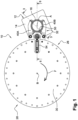
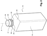
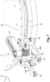
- FIG. 1 We represented at the figure 1 a device 10 for orienting a container 12 about its main axis "A" of vertical orientation.
- the container 12 comprises a lower body 14 which is open upwards via a neck 16 upper.
- the upper neck 16 has an outer face 17 of generally cylindrical shape of circular cross-section centered on the main axis "A" of the container 12.
- the neck 16 has at its base a first lower collar 18 and a second upper collar 20 which both project radially with respect to the outer face 17 .
- the two collars 18, 20 are separated vertically so as to define a groove 22.
- This groove 22 is intended in particular to receive a tamper evident ring (not shown) when the container 12 is sealed.
- the transition between the body 14 and the neck 16 is formed by a shoulder 23 pyramidal at its base and conical at its upper end.
- the section 24 of the outer face 17 delimited between the lower flange 18 and the shoulder 23 has a cylindrical shape of revolution centered on the axis "A" of the container. This section 24 will subsequently be called “grip section 24".
- the body 14 of the container 12 has at least one section which is not cylindrical of revolution.
- the body 14 has a square-shaped cross section over its entire height.
- the gripping section is formed by the bottom of the groove.
- the device 10 for orienting the receptacle 12 is intended to convey the receptacle from a point 26 of entry to a point 28 of exit.
- the orientation device 10 comprises a movable support 30 on which at least one gripper 32 is embedded.
- the movable support 30 is formed by a wheel 30 which is rotatably mounted about a central vertical axis "B".
- the wheel 30 is intended to be driven in rotation, in the direction indicated by the arrow "F", by drive means not shown.
- the wheel 30 comprises a plurality of grippers 32 for gripping the container 12 from the outside which are regularly distributed over its periphery. All the clamps 32 being identical, for the clarity of the drawings, only one gripping clamp 32 has been shown.
- Clamps 32 rotate integrally with wheel 30.
- clamps 32 are movable along a closed path, here circular.
- each container 12 gripped by a gripper 32 is transported from the entry point 26 to the exit point 28 following an arcuate path.
- the trajectory of the gripper 32 thus has a first so-called “useful” section on which it transports a container 12 towards the exit point 28, and a so-called “return” section over which the gripper travels empty towards the point 26 d 'entrance.
- each gripper 32 is intended to grip the container 12 by tightening the neck 16 at the level of the section 24 for gripping. This makes it possible to block the container 12 vertically in both directions by abutment of the jaws of the clamp 32 against the lower collar 18, on the one hand, and against the shoulder 23, on the other hand.
- the wheel is replaced by a chain or by any other known mobile support on which identical clamps are embedded.
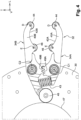
- the gripper 32 has been shown in more detail at figure 4 .
- the gripper 32 here comprises a first branch 34A and a second branch 34B longitudinal.
- the branches 34A, 34B are generally oriented radially with respect to the axis "B" of the wheel 30 so that a free front end of each branch 34A, 34B is arranged projecting radially with respect to the periphery of the wheel 30 .
- the first branch 34A is pivotally mounted on the wheel 30 about a vertical axis "C1" of pivoting which crosses the branch 34A globally in its middle.
- the second branch 34B is pivotally mounted on the wheel 30 about a vertical axis "C2" of pivoting which crosses the branch 34B globally in its middle.
- the two pivot axes "C1, C2" are offset transversely relative to each other.
- the two branches 34A, 34B are arranged in the same horizontal plane.
- each branch has an associated jaw 40A, 40B.
- Each jaw 40A, 40B has a concavely curved internal face 42A, 42B which is arranged transversely opposite the internal face 42B, 42A of the other jaw 40B, 40A.
- the clamp 32 is elastically returned to its clamping position by means of an elastic member 43 which is interposed between the two branches 34A, 34B.
- the elastic member 43 is here formed by a helical spring which is interposed transversely between two sections of branches 34A, 34B which are located behind the pivot axes C1, C2. The elastic member 43 thus tends to separate the two sections of branches 34A, 34B, thus bringing the two jaws 40A, 40B closer together by leverage.
- the opening of the gripper 32 towards its release position is controlled by a cam follower 45, here a follower roller, which cooperates with a cam 47, referred to as gripping cam 47 thereafter.
- the gripping cam 47 is fixed.
- the wheel 30 rotates relative to the gripping cam 47.
- the cam follower roller 45 is arranged at a rear end of the second branch 34B.
- the first branch 34A is controlled in pivoting in a direction opposite to that of the second branch 34B via toothed sectors 49A, 49B which are centered on the axes "C1", “C2" respectively.
- the cam follower roller 45 rolls on the gripping cam 47 to control the pivoting of the second branch 34B towards its release position, this movement being transmitted to the first branch 34A by the intermediate sectors 49A, 49B toothed.
- the cam follower roller 45 is held in contact with the gripping cam 47 by the elastic member 43.
- the container 12 thus gripped by the gripper 32 is intended to be pivoted around its main axis "A" so that its body 14 presents itself in a suitable orientation for the next operation, for example a labeling operation.
- a labeling operation for example a labeling operation.
- the container 12 in the gripping position of the jaws 40A, 40B, the container 12 is guided in rotation around its axis "A" with respect to the jaws 40A, 40B.
- the container 12 is more particularly received rolling between the jaws 40A, 40B of the clamp 32.
- the jaws have sliding faces which are intended to guide the container in rotation by sliding.
- each jaw 40A, 40B comprises at least one roller which projects radially inward relative to its inner face 42A, 42B to guide the rotation of the container 12 gripped by the jaws 40A, 40B.
- the neck 16 is thus in contact only with the running rollers of the jaws 40A, 40B when they occupy their pinching position.
- each jaw 40A, 40B is provided with two rollers.
- a guide roller 44 is mounted free to rotate around a vertical axis "D" at a free front end of the associated jaws 40A, 40B.
- This guide roller 44 comprises a circular segment which projects transversely with respect to the internal face 42A, 42B of the associated jaws 40A, 40B.
- the projecting circular segment of the guide roller 44 comes directly into contact with the gripping section 24 of the container 12 when the gripper 32 occupies its gripping position.
- Clamp 32 thus comprises two guide rollers 44, one for each jaw 40A, 40B.
- the two guide rollers are arranged in the same horizontal plane.
- a drive roller 46 is mounted free to rotate around a vertical axis "E" at the rear end of the internal face 42A, 42B of the associated jaws 40A, 40B.
- This drive roller 46 comprises a circular segment which projects transversely with respect to the internal face 42A, 42B of the associated jaws 40A, 40B.
- the projecting circular segment of the drive roller 46 comes directly into contact with the gripping section 24 of the container 12 when the gripper 32 occupies its gripping position.
- Clamp 32 thus comprises two drive rollers 46, one for each jaw 40A, 40B.
- the two drive rollers 46 are arranged in the same horizontal plane.
- the gripping section 24 of the container 12 is thus in contact only with the rollers 44, 46.
- the container 12 is thus carried in cooperation by the drive rollers 46 and by the rollers 44 of guidance.
- a radial space is thus reserved between the inner face 42A, 42B of each jaw 40A, 40B to promote rotation without friction of the container 12 around its axis "A" with respect to the jaws 40A, 40B.
- the drive rollers 46 have a function of driving the container 12 in rotation, on the one hand, and a function of supporting the container 12, on the other hand.
- the jaws are spaced apart transversely from one another.
- the pair of guide rollers 44 is thus spaced apart transversely, as is the pair of drive rollers 46, thus allowing the release of the seized container 12, or the reception of a new container 12.
- Each roller 44, 46 has a rim which is made of a material which promotes rolling by friction of said roller 44, 46 against the section 24 for gripping the container. Thus, as long as the container 12 encounters no obstacle preventing its rotation, the drive rollers 46 roll without slipping against the gripping section 24 .
- the guide rollers are replaced by sliding faces of the jaws which are intended to guide the container in rotation by sliding.
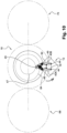
- the device 10 is also equipped with a member 48 controlled for simultaneous rotation of the drive rollers 46.
- the container 12 is rotated simultaneously by the two drive rollers 46. This makes it possible to guarantee the triggering of the rotation of the container 12 by friction of the rollers 46 for driving.
- each jaw 40A, 40B is equipped with an associated drive roller 46.
- the two drive rollers 46 are offset circumferentially with respect to each other around the axis "A" of the container 12. This makes it possible to guarantee good stability of the container 12 during its rotation.
- each gripper 32 comprises an associated rotating member 48 .
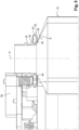
- Rotation member 48 comprises an element 50 which is mounted to rotate on wheel 30 about a vertical axis "G".
- the axis "G” is arranged equidistant from the two drive rollers 46.
- the rotating element 50 is thus movable together with the gripper 32.
- the rotating element 50 comprises at least two peripheral faces in an arc of a circle, each of which is intended to roll without slipping against an associated drive roller 46 when the clamp 32 occupies its clamping position.
- the rotating element 50 has an annular rim 52 centered on the axis "G".
- the axis "G" is here arranged longitudinally behind the drive rollers 46 and the diameter of the rim 52 is greater than the transverse distance which separates the two drive rollers 46.
- the drive rollers 46 are in contact with this annular rim 52 when the clamp 32 occupies its clamping position.
- the points of contact of the rim 52 with the drive rollers 46 here form an angle "a" less than 180°, here approximately 30°, with respect to the axis "G" of the rotating element 50.
- the rotating element 50 is mounted on the wheel 30 by means of a longitudinal arm 54 which is fixed to an upper face of the wheel 30.
- a front end of the arm 54 which carries a bearing 56 of bearing extends projecting from the peripheral edge of the wheel 30.
- the rotating element 50 comprises a central vertical shaft 58 of axis "G" which is received in the bearing 56.
- the rotating element 50 is thus arranged under the wheel 30, at the same level as the drive rollers 46.
- Rotation member 48 also includes a crank pin 60 which is fixed to element 50 rotating eccentrically with respect to axis "G" of rotation.
- the pin 60 is more particularly arranged under the wheel 30, behind the axis "G” of rotation of the rotating element 50.
- the rotating element has a crank arm 62 which extends radially projecting with respect to the annular rim 52.
- the crank pin 60 is carried by a free end of the crank arm 62.
- the crank pin 60 is here formed by a free roller in rotation around a vertical axis.
- the device 10 also comprises a cam 64 which makes it possible to control the pivoting of the rotating element 50 by rolling the crankpin 60 on the cam track 64 during the movement of the gripper 32 along its trajectory.
- This cam 64 will be referred to below as "orientation cam 64".
- the orientation cam 64 is fixed relative to the gripping cam 47.
- the rotating element 50 is also provided with elastic return means which constrain the pin 60 against the orientation cam 64 and which return the rotating element 50 to an angular position of rest.
- These return means are formed by a spiral torsion spring 66 which is arranged around the shaft 58.
- the torsion spring 66 is interposed vertically between the arm 54 and the rotating element 50.
- a lower end of torsion spring 66 is attached to rotating member 50 while an upper end is attached to arm 54, arm 54 being fixed relative to wheel 30.
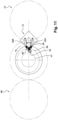
- the orientation cam 64 is designed to cause the rotating element 50 to pivot over an angular travel defined between a first extreme angular position and a second extreme angular position. These two extreme angular positions are arranged beyond the rest position of the rotating element 50 so that the crank pin 60 is constantly forced against the orientation cam 64 over the entire trajectory of the gripper 32.
- This angular travel allows to drive the drive rollers 46 to rotate the container 12 through an angle less than 360° about its axis.
- a pivoting of an angle of less than 180°, or even less than 90° is sufficient to place the container 12 in the correct orientation for the next operation, for example for the labeling operation.
- the pivoting of the container around its axis is limited by abutment means which are movable together with the clamp 32 and which are intended to cooperate with an abutment face carried by the container.
- the abutment face of the receptacle is for example carried by a abutment finger which projects radially from the gripping section of the receptacle and which is capable of coming into abutment against one of the guide or drive rollers.
- the clamp abutment means are therefore formed by the rollers.
- the abutment means are formed by a face carried by the wheel 30. They cooperate with a non-circular section of the body of the container to block its rotation against the pivoting imposed by the rotation of the drive rolls.
- the device 10 comprises means for adjusting the longitudinal position of the rotating element 50 with respect to the associated gripper 32.
- the arm 54 which carries the rotating element 50 is mounted to slide longitudinally on the wheel 30.
- the arm 54 has a longitudinal slot which is traversed by two fixing screws. By loosening the fixing screws it is possible to slide the arm 54.
- the device also comprises means for adjusting the amplitude of the angular stroke of the rotating element.
- the position of the crank pin is adjustable in a radial direction with respect to the axis of rotation of the rotating element. This thus makes it possible to vary the amplitude of the angular travel in proportion to the radial distance between the crankpin and the axis of rotation of the rotating element.
- At least one section of the orientation cam is movable transversely with respect to the direction of movement of the gripper.
- the drive rollers 46 are separated from the rim 52 of the rotating element 50.
- the rotating element 50 occupies a first extreme angular position, called the entry angular position, towards which it is returned by the torsion spring 66.
- a container 12 is transported by an upstream transport device 68, for example a transfer wheel, to the point 26 of entry.
- an upstream transport device 68 for example a transfer wheel
- the container 12 and the clamp 32 arrive simultaneously at the entry point 26 so that the neck 16 of the container 12 is received between the jaws 40A, 40B.
- the jaws 40A, 40B are then controlled by the cam follower roller 45 and by the gripping cam 47 in the gripping position of the section 24 for gripping the container against the elastic return force of the elastic member 43 .
- Each drive roller 46 then simultaneously comes into contact with the gripping section 24, on the one hand, and with the rim 52 of the rotating element 50, on the other hand.
- the container 12 is thus held by the clamp 32, and guided in rotation, via the guide rollers 44 and the drive rollers 46.
- the clamp 32 continues its trajectory in the direction of the exit point 28 carrying the container 12.
- the rotating element 50 is pivoted from its determined angular stroke to its second extreme angular position, called the exit angular position, by the crankpin 60 rolling on the cam 64 orientation.
- the second exit angular position is closer to the rest angular position than the entry angular position.
- the orientation cam 64 moves radially away from the path of the axis "G" of rotation of the rotating element 50 during this movement.
- This pivoting in a clockwise direction of the rotating element 50 is transmitted to the container 12 via the drive rollers 46 to rotate the container 12 through a determined angle, here approximately 45°, in a counterclockwise direction.
- the clamp 32 remains in the clamping position.
- the clamp 32 ends the useful section of its trajectory arriving at the point 28 of exit.
- the orientation cam 64 maintains the rotating element 50 in its angular output position, while the gripping cam 47 controls the opening of the gripper 32 in the release position.
- the container 12 thus correctly oriented is transmitted to a downstream transport device 70, for example a second transfer wheel or a carousel of a labeling station.
- a downstream transport device 70 for example a second transfer wheel or a carousel of a labeling station.
- the clamp 32 continues its movement on the "return" section of its trajectory.
- the clamp 32 remains in the released position while the orientation cam 64 makes it possible to control, via the pin 60, the element 50 rotating towards its first angular entry position against the force of elastic return of the torsion spring 66.
- the orientation device 10 produced according to the teachings of the invention thus makes it possible to pivot each container 12 in a reliable and stable manner thanks to a device that is inexpensive and simple to produce.
Landscapes
- Engineering & Computer Science (AREA)
- Mechanical Engineering (AREA)
- Specific Conveyance Elements (AREA)
- Wrapping Of Specific Fragile Articles (AREA)
Claims (13)
- Vorrichtung (10) zum Ausrichten mindestens eines Behälters (12) um seine vertikale Ausrichtungsachse (A) für einen Behälter (12), der einen unteren Körper (14) umfasst, der über einen Hals (16) nach oben offen ist, der eine Außenfläche (17) von insgesamt zylindrischer Form mit kreisförmigem Querschnitt, der auf die Hauptachse "A" des Behälters (12) zentriert ist, aufweist und der an seiner Basis einen unteren Kragen (18) und einen zweiten, oberen Kragen (20) umfasst, die beide radial bezüglich der Außenfläche (17) vorragen, wobei die beiden Kragen (18, 20) vertikal beabstandet sind, so dass sie eine Auskehlung (22) definieren, wobei der Übergang zwischen dem Körper (14) und dem Hals (16) durch eine Schulter (23) gebildet wird, die an ihrer Basis pyramidenförmig und an ihrem oberen Ende konisch ist, wobei der Behälter über einen Greifabschnitt (24) verfügt, der zwischen dem unteren Kragen (18) und der Schulter (23) begrenzt ist oder durch den Boden der Auskehlung (22), die zwischen den beiden Kragen (18, 20) definiert ist, wobei der Greifabschnitt (24) eine Außenfläche (17) hat und eine zylindrische Rotationsform aufweist, die auf die Achse (A) des Behälters zentriert ist, wobei die Vorrichtung (10) mindestens eine Klemme (32) zum Greifen des Behälters (12) umfasst, die entlang einer bestimmten Bahn bewegbar montiert ist, wobei die Klemme (32) mindestens zwei Backen (40A, 40B) umfasst, die eine erste Position zum Klemmen des Greifabschnitts (24) und eine Position zum Freigeben des Behälters (12) einnehmen können;wobei die Vorrichtung ein gesteuertes Organ (48) zum Drehen einer ersten Antriebsrolle (46) umfasst, um den Behälter (12) um einen Winkel kleiner als 360° zu schwenken;dadurch gekennzeichnet, dass der Greifabschnitt (24) in Bezug auf die Backen (40A, 40B) um seine Achse (A) drehbar geführt wird, wenn die zwei Backen die erste Position zum Klemmen des Greifabschnitts (24) einnehmen, wobei die erste Antriebsrolle (46) eine Antriebsrolle zum Drehen des durch die Klemme (32) gehaltenen Behälters durch Abwälzen der Antriebsrolle (46) auf dem Greifabschnitt (24) ist; unddass die Klemme (32) das gesteuerte Organ (48) zum Drehen der ersten Antriebsrolle umfasst und eine zweite Antriebsrolle (46) zum Drehen des durch die Klemme (32) gehaltenen Behälters (12) durch schlupffreies Abwälzen der zweiten Rolle (46) auf dem Greifabschnitt (24) umfasst.
- Vorrichtung (10) nach dem vorhergehenden Anspruch, dadurch gekennzeichnet, dass die zweite Antriebsrolle (46) in Bezug auf die erste Antriebsrolle (46) in Umfangsrichtung versetzt ist.
- Vorrichtung (10) nach dem vorhergehenden Anspruch, dadurch gekennzeichnet, dass die zweite Antriebsrolle (46) in einer gleichen Ebene wie die erste Antriebsrolle (46) angeordnet ist.
- Vorrichtung (10) nach einem der vorhergehenden Ansprüche, dadurch gekennzeichnet, dass die erste Antriebsrolle (46) und die zweite Antriebsrolle (46) durch das Drehorgan (48) gleichzeitig in Drehung versetzt werden.
- Vorrichtung (10) nach einem der vorhergehenden Ansprüche, dadurch gekennzeichnet, dass das Drehorgan (48) ein um eine vertikale Achse (G) rotierendes Element (50) umfasst, das gemeinsam mit der Klemme (32) bewegbar ist und das mindestens zwei kreisbogenförmige Umfangsflächen (52) umfasst, von denen jede dazu bestimmt ist, schlupffrei auf einer assoziierten Antriebsrolle (46) abzuwälzen, wenn die Klemme (32) ihre Klemmposition einnimmt.
- Vorrichtung (10) nach dem vorhergehenden Anspruch, dadurch gekennzeichnet, dass das Drehorgan (48) einen Zapfen (60) umfasst, der in Bezug auf die Drehachse (G) des rotierenden Elements (50) exzentrisch angeordnet ist, wobei die Vorrichtung (10) ferner einen stationären Nocken (64) umfasst, mit dem die Drehung des rotierenden Elements (50) durch Kontakt des Zapfens (60) mit dem Nocken (64) gesteuert werden kann, wenn sich die Klemme (32) entlang ihrer Bahn bewegt, wobei das rotierende Element (50) über elastische Rückstellmittel (66) verfügt, die den Zapfen (60) gegen den Nocken (64) drängen.
- Vorrichtung (10) nach einem der vorhergehenden Ansprüche, dadurch gekennzeichnet, dass die Klemme (32) dazu bestimmt ist, den Behälter (12) an seinem Hals (16) zu halten.
- Vorrichtung (10) nach einem der vorhergehenden Ansprüche, dadurch gekennzeichnet, dass die Backen Gleitflächen umfassen, die dazu bestimmt sind, den Behälter durch Gleiten drehbar zu führen.
- Vorrichtung (10) nach einem der Ansprüche 1 bis 8, dadurch gekennzeichnet, dass die Backen (40A, 40B) mindestens eine frei drehbare Führungsrolle (44) umfassen, die dazu bestimmt ist, den Behälter (12) in Bezug auf die Klemme (32) durch Abwälzen drehbar zu führen.
- Vorrichtung (10) nach dem vorhergehenden Anspruch, dadurch gekennzeichnet, dass die Führungsrollen (44) auf derselben Höhe wie die Antriebsrollen (46) angeordnet sind, wobei der Behälter (12) von den Antriebsrollen (46) und von den Führungsrollen (44) gemeinsam getragen wird.
- Vorrichtung (10) nach einem der vorhergehenden Ansprüche, dadurch gekennzeichnet, dass sie Mittel (54) zum Einstellen der Position des rotierenden Elements (50) in Bezug auf die assoziierte Klemme (32) umfasst.
- Vorrichtung (10) nach einem der vorhergehenden Ansprüche, dadurch gekennzeichnet, dass die Klemmen (32) entlang einer geschlossenen Bahn bewegbar sind und dass der Nocken (64) dazu ausgelegt ist, das rotierende Element (50) auf einem winkelförmigen Weg, der zwischen einer ersten Winkelendlage und einer zweiten Winkelendlage liegt, zu schwenken.
- Vorrichtung (10) nach einem der vorhergehenden Ansprüche, dadurch gekennzeichnet, dass sie mit Anschlagmitteln für das Schwenken des Behälters ausgerüstet ist, die dazu bestimmt sind, mit einer Anschlagfläche des Behälters zusammenzuwirken, um dessen Schwenkbewegung in einer bestimmten Winkelposition zu stoppen.
Applications Claiming Priority (2)
| Application Number | Priority Date | Filing Date | Title |
|---|---|---|---|
| FR1462040A FR3029511B1 (fr) | 2014-12-08 | 2014-12-08 | "dispositif d'orientation d'un recipient comportant deux galets d'entrainement du recipient" |
| PCT/FR2015/053270 WO2016092180A1 (fr) | 2014-12-08 | 2015-12-01 | Dispositif d'orientation d'un récipient comportant deux galets d'entraînement du récipient |
Publications (3)
| Publication Number | Publication Date |
|---|---|
| EP3230185A1 EP3230185A1 (de) | 2017-10-18 |
| EP3230185B1 EP3230185B1 (de) | 2020-08-12 |
| EP3230185B2 true EP3230185B2 (de) | 2023-06-07 |
Family
ID=52424003
Family Applications (1)
| Application Number | Title | Priority Date | Filing Date |
|---|---|---|---|
| EP15820560.9A Active EP3230185B2 (de) | 2014-12-08 | 2015-12-01 | Vorrichtung zur herstellung eines behälters mit zwei rollen zur ansteuerung eines behälters |
Country Status (3)
| Country | Link |
|---|---|
| EP (1) | EP3230185B2 (de) |
| FR (1) | FR3029511B1 (de) |
| WO (1) | WO2016092180A1 (de) |
Families Citing this family (6)
| Publication number | Priority date | Publication date | Assignee | Title |
|---|---|---|---|---|
| IT201800010665A1 (it) * | 2018-11-28 | 2020-05-28 | Gea Procomac Spa | Procedimento per trasferire un recipiente in materiale termoplastico avente un fondo poligonale, ad esempio rettangolare o quadrato, da un punto di prelievo di una prima unità rotante ad un punto di consegna di una seconda unità rotante |
| CN110044912B (zh) * | 2019-05-21 | 2023-10-10 | 齐鲁工业大学(山东省科学院) | 一种小口径密闭容器内壁表面缺陷检测装置 |
| DE102020114391B4 (de) * | 2020-05-28 | 2025-10-23 | Etw Wollmershäuser Gmbh | Förderanlagenvorrichtung und Förderanlage zu einem geordneten Fördern von länglich erstreckten Objekten wie Ampullen, Karpulen, Spritzen, Pipetten, Vials oder dergleichen |
| IT202000014836A1 (it) * | 2020-06-22 | 2021-12-22 | Arol Spa | Dispositivo di manipolazione di contenitori per impianti di tappatura |
| DE102021129959A1 (de) * | 2021-11-17 | 2023-05-17 | Krones Aktiengesellschaft | Vorrichtung und Verfahren zum Transportieren von Behältnissen mit rollengestütztem Stellmechanismus für Greifklammern |
| CN223291810U (zh) * | 2024-08-09 | 2025-09-02 | 无锡先导智能装备股份有限公司 | 一种夹具、输送线及纠偏系统 |
Citations (1)
| Publication number | Priority date | Publication date | Assignee | Title |
|---|---|---|---|---|
| US2528860A (en) † | 1949-07-05 | 1950-11-07 | Wright Machinery Co | Article holding means |
Family Cites Families (9)
| Publication number | Priority date | Publication date | Assignee | Title |
|---|---|---|---|---|
| FR1539990A (fr) * | 1967-08-24 | 1968-09-20 | Anker Maschb Gmbh | Dispositif pour la mise à l'alignement de bouteilles ou de récipients analogues avant l'étiquetage par rotation autour de leur axe |
| DE7013118U (de) | 1970-04-10 | 1970-07-23 | Kronseder Hermann | Vorrichtung zum ausrichten von mit nocken versehenen flaschen in etikettiermaschinen. |
| DE2740220C2 (de) * | 1977-09-07 | 1982-10-28 | Kronseder, Hermann, 8404 Wörth | Vorrichtung zum Ausrichten von Flaschen vor dem Etikettieren |
| DE3022343C2 (de) | 1980-06-14 | 1983-10-20 | Kronseder, Hermann, 8404 Wörth | Vorrichtung zum Ausrichten von Flaschen o.dgl., insbesondere in Etikettiermaschinen |
| FR2500361A1 (fr) | 1981-02-23 | 1982-08-27 | Solvay | Preforme en matiere thermoplastique comportant une couronne dentee circulaire, destinee a assurer sa rotation, lors du conditionnement thermique qui precede le moulage par soufflage |
| US4468277A (en) * | 1983-07-05 | 1984-08-28 | Owens-Illinois, Inc. | Fixed jaw means for holding and rotating containers traveling around a turret periphery |
| US5259716A (en) | 1987-12-16 | 1993-11-09 | Dai Nippon Insatsu Kabushiki Kaisha | Container conveyor for conveying a container to an inspecting station |
| DE102005048358A1 (de) | 2004-11-30 | 2006-08-24 | Sig Technology Ltd. | Verfahren und Vorrichtung zum Transport von Vorformlingen |
| DE102012112158A1 (de) | 2012-12-12 | 2014-06-12 | Krones Ag | Vorrichtung zum Sterilisieren von Kunststoffvorformlingen |
-
2014
- 2014-12-08 FR FR1462040A patent/FR3029511B1/fr active Active
-
2015
- 2015-12-01 WO PCT/FR2015/053270 patent/WO2016092180A1/fr not_active Ceased
- 2015-12-01 EP EP15820560.9A patent/EP3230185B2/de active Active
Patent Citations (1)
| Publication number | Priority date | Publication date | Assignee | Title |
|---|---|---|---|---|
| US2528860A (en) † | 1949-07-05 | 1950-11-07 | Wright Machinery Co | Article holding means |
Also Published As
| Publication number | Publication date |
|---|---|
| FR3029511B1 (fr) | 2019-04-12 |
| WO2016092180A1 (fr) | 2016-06-16 |
| EP3230185A1 (de) | 2017-10-18 |
| EP3230185B1 (de) | 2020-08-12 |
| FR3029511A1 (fr) | 2016-06-10 |
Similar Documents
| Publication | Publication Date | Title |
|---|---|---|
| EP3230185B2 (de) | Vorrichtung zur herstellung eines behälters mit zwei rollen zur ansteuerung eines behälters | |
| EP1116675B1 (de) | Vorrichtung zur Bildung von aufeinanderfolgenden Gruppen von Artikeln mit Mitteln zur Überführung der Artikel | |
| EP1922273B1 (de) | Verfahren zum laden oder entladen von behältern mit einem hals auf ein transportelement | |
| EP1781460B1 (de) | Vorformförderanlage mit vorrichtung zum auswurf schlecht erfasster vorformen | |
| WO2010037924A1 (fr) | Procede et dispositif de positionnement de recipients et installation de traitement de recipients ayant des sections differentes | |
| EP0012659A1 (de) | Vorrichtung und Verfahren zum Ausrichten bedruckter Flaschenkapseln | |
| EP1922272B1 (de) | Vorrichtung zum laden von behältern auf ein transportelement mit mittel zum auswurf falsch geladener behälter | |
| FR3058404A1 (fr) | Systeme de convoyage d'objets en matiere thermoplastique comportant un corps creux muni d'un col | |
| FR2958275A1 (fr) | Dispositif pour le transport d'une preforme avec rotation de la preforme autour de son axe principal | |
| FR2801045A1 (fr) | Systeme de convoyage d'entites discretes comportant un dispositif de repartition et installation de soufflage de recipients munie d'un tel systeme | |
| FR2639613A1 (fr) | Machine pour emballer des cigarettes dans des paquets durs a dessus basculant | |
| EP2684822B1 (de) | Vorrichtung zum Vergrössern eines Schritts für eine positive und individuelle Übertragung von Objekten | |
| FR2911849A1 (fr) | Procede pur le retournement et l'encaissage de deux bouteilles ou flacons. | |
| WO2012130973A1 (fr) | Dispositif de transfert de recipients avec indexation angulaire par contact entre un element d'indexation et un troncon cylindrique du recipient | |
| FR2639614A1 (fr) | Procede pour emballer des cigarettes dans des paquets durs a dessus basculant | |
| EP0573352B1 (de) | Einrichtung zum Laden von Behältern auf ein Transportglied | |
| WO2013079852A1 (fr) | Dispositif pour le deplacement en continu de bouteilles de gaz en direction d'une machine de remplissage | |
| EP2861514B1 (de) | Übertragungsvorrichtung für hohlkörper mit variabler teilung | |
| WO2024068822A1 (fr) | Procede de transfert de preforme sur un convoyeur | |
| WO2020128406A1 (fr) | Procédé de contrôle de la synchronisation de deux roues de transport de corps creux | |
| FR2810651A1 (fr) | Dispositif pour la constitution de lots successifs d'articles comprenant des moyens de transfert des articles, et installation comprenant ce dispositif | |
| EP0353176A1 (de) | Vorrichtung zum Beleimen und Übertragen von Etiketten in Etikettiermaschinen für Verpackungen |
Legal Events
| Date | Code | Title | Description |
|---|---|---|---|
| STAA | Information on the status of an ep patent application or granted ep patent |
Free format text: STATUS: THE INTERNATIONAL PUBLICATION HAS BEEN MADE |
|
| PUAI | Public reference made under article 153(3) epc to a published international application that has entered the european phase |
Free format text: ORIGINAL CODE: 0009012 |
|
| STAA | Information on the status of an ep patent application or granted ep patent |
Free format text: STATUS: REQUEST FOR EXAMINATION WAS MADE |
|
| 17P | Request for examination filed |
Effective date: 20170531 |
|
| AK | Designated contracting states |
Kind code of ref document: A1 Designated state(s): AL AT BE BG CH CY CZ DE DK EE ES FI FR GB GR HR HU IE IS IT LI LT LU LV MC MK MT NL NO PL PT RO RS SE SI SK SM TR |
|
| AX | Request for extension of the european patent |
Extension state: BA ME |
|
| DAV | Request for validation of the european patent (deleted) | ||
| DAX | Request for extension of the european patent (deleted) | ||
| STAA | Information on the status of an ep patent application or granted ep patent |
Free format text: STATUS: EXAMINATION IS IN PROGRESS |
|
| 17Q | First examination report despatched |
Effective date: 20180802 |
|
| GRAP | Despatch of communication of intention to grant a patent |
Free format text: ORIGINAL CODE: EPIDOSNIGR1 |
|
| STAA | Information on the status of an ep patent application or granted ep patent |
Free format text: STATUS: GRANT OF PATENT IS INTENDED |
|
| INTG | Intention to grant announced |
Effective date: 20200323 |
|
| GRAS | Grant fee paid |
Free format text: ORIGINAL CODE: EPIDOSNIGR3 |
|
| GRAA | (expected) grant |
Free format text: ORIGINAL CODE: 0009210 |
|
| STAA | Information on the status of an ep patent application or granted ep patent |
Free format text: STATUS: THE PATENT HAS BEEN GRANTED |
|
| AK | Designated contracting states |
Kind code of ref document: B1 Designated state(s): AL AT BE BG CH CY CZ DE DK EE ES FI FR GB GR HR HU IE IS IT LI LT LU LV MC MK MT NL NO PL PT RO RS SE SI SK SM TR |
|
| REG | Reference to a national code |
Ref country code: CH Ref legal event code: EP |
|
| REG | Reference to a national code |
Ref country code: DE Ref legal event code: R096 Ref document number: 602015057456 Country of ref document: DE |
|
| REG | Reference to a national code |
Ref country code: IE Ref legal event code: FG4D Free format text: LANGUAGE OF EP DOCUMENT: FRENCH |
|
| REG | Reference to a national code |
Ref country code: AT Ref legal event code: REF Ref document number: 1301370 Country of ref document: AT Kind code of ref document: T Effective date: 20200915 |
|
| REG | Reference to a national code |
Ref country code: LT Ref legal event code: MG4D |
|
| REG | Reference to a national code |
Ref country code: NL Ref legal event code: MP Effective date: 20200812 |
|
| PG25 | Lapsed in a contracting state [announced via postgrant information from national office to epo] |
Ref country code: GR Free format text: LAPSE BECAUSE OF FAILURE TO SUBMIT A TRANSLATION OF THE DESCRIPTION OR TO PAY THE FEE WITHIN THE PRESCRIBED TIME-LIMIT Effective date: 20201113 Ref country code: NO Free format text: LAPSE BECAUSE OF FAILURE TO SUBMIT A TRANSLATION OF THE DESCRIPTION OR TO PAY THE FEE WITHIN THE PRESCRIBED TIME-LIMIT Effective date: 20201112 Ref country code: FI Free format text: LAPSE BECAUSE OF FAILURE TO SUBMIT A TRANSLATION OF THE DESCRIPTION OR TO PAY THE FEE WITHIN THE PRESCRIBED TIME-LIMIT Effective date: 20200812 Ref country code: HR Free format text: LAPSE BECAUSE OF FAILURE TO SUBMIT A TRANSLATION OF THE DESCRIPTION OR TO PAY THE FEE WITHIN THE PRESCRIBED TIME-LIMIT Effective date: 20200812 Ref country code: BG Free format text: LAPSE BECAUSE OF FAILURE TO SUBMIT A TRANSLATION OF THE DESCRIPTION OR TO PAY THE FEE WITHIN THE PRESCRIBED TIME-LIMIT Effective date: 20201112 Ref country code: SE Free format text: LAPSE BECAUSE OF FAILURE TO SUBMIT A TRANSLATION OF THE DESCRIPTION OR TO PAY THE FEE WITHIN THE PRESCRIBED TIME-LIMIT Effective date: 20200812 Ref country code: LT Free format text: LAPSE BECAUSE OF FAILURE TO SUBMIT A TRANSLATION OF THE DESCRIPTION OR TO PAY THE FEE WITHIN THE PRESCRIBED TIME-LIMIT Effective date: 20200812 |
|
| REG | Reference to a national code |
Ref country code: AT Ref legal event code: MK05 Ref document number: 1301370 Country of ref document: AT Kind code of ref document: T Effective date: 20200812 |
|
| PG25 | Lapsed in a contracting state [announced via postgrant information from national office to epo] |
Ref country code: IS Free format text: LAPSE BECAUSE OF FAILURE TO SUBMIT A TRANSLATION OF THE DESCRIPTION OR TO PAY THE FEE WITHIN THE PRESCRIBED TIME-LIMIT Effective date: 20201212 Ref country code: PL Free format text: LAPSE BECAUSE OF FAILURE TO SUBMIT A TRANSLATION OF THE DESCRIPTION OR TO PAY THE FEE WITHIN THE PRESCRIBED TIME-LIMIT Effective date: 20200812 Ref country code: RS Free format text: LAPSE BECAUSE OF FAILURE TO SUBMIT A TRANSLATION OF THE DESCRIPTION OR TO PAY THE FEE WITHIN THE PRESCRIBED TIME-LIMIT Effective date: 20200812 Ref country code: NL Free format text: LAPSE BECAUSE OF FAILURE TO SUBMIT A TRANSLATION OF THE DESCRIPTION OR TO PAY THE FEE WITHIN THE PRESCRIBED TIME-LIMIT Effective date: 20200812 Ref country code: LV Free format text: LAPSE BECAUSE OF FAILURE TO SUBMIT A TRANSLATION OF THE DESCRIPTION OR TO PAY THE FEE WITHIN THE PRESCRIBED TIME-LIMIT Effective date: 20200812 |
|
| PG25 | Lapsed in a contracting state [announced via postgrant information from national office to epo] |
Ref country code: DK Free format text: LAPSE BECAUSE OF FAILURE TO SUBMIT A TRANSLATION OF THE DESCRIPTION OR TO PAY THE FEE WITHIN THE PRESCRIBED TIME-LIMIT Effective date: 20200812 Ref country code: CZ Free format text: LAPSE BECAUSE OF FAILURE TO SUBMIT A TRANSLATION OF THE DESCRIPTION OR TO PAY THE FEE WITHIN THE PRESCRIBED TIME-LIMIT Effective date: 20200812 Ref country code: RO Free format text: LAPSE BECAUSE OF FAILURE TO SUBMIT A TRANSLATION OF THE DESCRIPTION OR TO PAY THE FEE WITHIN THE PRESCRIBED TIME-LIMIT Effective date: 20200812 Ref country code: SM Free format text: LAPSE BECAUSE OF FAILURE TO SUBMIT A TRANSLATION OF THE DESCRIPTION OR TO PAY THE FEE WITHIN THE PRESCRIBED TIME-LIMIT Effective date: 20200812 Ref country code: EE Free format text: LAPSE BECAUSE OF FAILURE TO SUBMIT A TRANSLATION OF THE DESCRIPTION OR TO PAY THE FEE WITHIN THE PRESCRIBED TIME-LIMIT Effective date: 20200812 |
|
| REG | Reference to a national code |
Ref country code: DE Ref legal event code: R026 Ref document number: 602015057456 Country of ref document: DE |
|
| PLBI | Opposition filed |
Free format text: ORIGINAL CODE: 0009260 |
|
| PG25 | Lapsed in a contracting state [announced via postgrant information from national office to epo] |
Ref country code: AL Free format text: LAPSE BECAUSE OF FAILURE TO SUBMIT A TRANSLATION OF THE DESCRIPTION OR TO PAY THE FEE WITHIN THE PRESCRIBED TIME-LIMIT Effective date: 20200812 Ref country code: AT Free format text: LAPSE BECAUSE OF FAILURE TO SUBMIT A TRANSLATION OF THE DESCRIPTION OR TO PAY THE FEE WITHIN THE PRESCRIBED TIME-LIMIT Effective date: 20200812 Ref country code: ES Free format text: LAPSE BECAUSE OF FAILURE TO SUBMIT A TRANSLATION OF THE DESCRIPTION OR TO PAY THE FEE WITHIN THE PRESCRIBED TIME-LIMIT Effective date: 20200812 |
|
| PLAX | Notice of opposition and request to file observation + time limit sent |
Free format text: ORIGINAL CODE: EPIDOSNOBS2 |
|
| 26 | Opposition filed |
Opponent name: KRONES AG Effective date: 20210505 |
|
| PG25 | Lapsed in a contracting state [announced via postgrant information from national office to epo] |
Ref country code: SK Free format text: LAPSE BECAUSE OF FAILURE TO SUBMIT A TRANSLATION OF THE DESCRIPTION OR TO PAY THE FEE WITHIN THE PRESCRIBED TIME-LIMIT Effective date: 20200812 |
|
| REG | Reference to a national code |
Ref country code: CH Ref legal event code: PL |
|
| GBPC | Gb: european patent ceased through non-payment of renewal fee |
Effective date: 20201201 |
|
| PG25 | Lapsed in a contracting state [announced via postgrant information from national office to epo] |
Ref country code: SI Free format text: LAPSE BECAUSE OF FAILURE TO SUBMIT A TRANSLATION OF THE DESCRIPTION OR TO PAY THE FEE WITHIN THE PRESCRIBED TIME-LIMIT Effective date: 20200812 Ref country code: MC Free format text: LAPSE BECAUSE OF FAILURE TO SUBMIT A TRANSLATION OF THE DESCRIPTION OR TO PAY THE FEE WITHIN THE PRESCRIBED TIME-LIMIT Effective date: 20200812 |
|
| REG | Reference to a national code |
Ref country code: BE Ref legal event code: MM Effective date: 20201231 |
|
| PLBB | Reply of patent proprietor to notice(s) of opposition received |
Free format text: ORIGINAL CODE: EPIDOSNOBS3 |
|
| PG25 | Lapsed in a contracting state [announced via postgrant information from national office to epo] |
Ref country code: IE Free format text: LAPSE BECAUSE OF NON-PAYMENT OF DUE FEES Effective date: 20201201 Ref country code: LU Free format text: LAPSE BECAUSE OF NON-PAYMENT OF DUE FEES Effective date: 20201201 |
|
| PG25 | Lapsed in a contracting state [announced via postgrant information from national office to epo] |
Ref country code: CH Free format text: LAPSE BECAUSE OF NON-PAYMENT OF DUE FEES Effective date: 20201231 Ref country code: LI Free format text: LAPSE BECAUSE OF NON-PAYMENT OF DUE FEES Effective date: 20201231 Ref country code: GB Free format text: LAPSE BECAUSE OF NON-PAYMENT OF DUE FEES Effective date: 20201201 |
|
| PG25 | Lapsed in a contracting state [announced via postgrant information from national office to epo] |
Ref country code: IS Free format text: LAPSE BECAUSE OF FAILURE TO SUBMIT A TRANSLATION OF THE DESCRIPTION OR TO PAY THE FEE WITHIN THE PRESCRIBED TIME-LIMIT Effective date: 20201212 Ref country code: TR Free format text: LAPSE BECAUSE OF FAILURE TO SUBMIT A TRANSLATION OF THE DESCRIPTION OR TO PAY THE FEE WITHIN THE PRESCRIBED TIME-LIMIT Effective date: 20200812 Ref country code: MT Free format text: LAPSE BECAUSE OF FAILURE TO SUBMIT A TRANSLATION OF THE DESCRIPTION OR TO PAY THE FEE WITHIN THE PRESCRIBED TIME-LIMIT Effective date: 20200812 Ref country code: CY Free format text: LAPSE BECAUSE OF FAILURE TO SUBMIT A TRANSLATION OF THE DESCRIPTION OR TO PAY THE FEE WITHIN THE PRESCRIBED TIME-LIMIT Effective date: 20200812 |
|
| PG25 | Lapsed in a contracting state [announced via postgrant information from national office to epo] |
Ref country code: MK Free format text: LAPSE BECAUSE OF FAILURE TO SUBMIT A TRANSLATION OF THE DESCRIPTION OR TO PAY THE FEE WITHIN THE PRESCRIBED TIME-LIMIT Effective date: 20200812 |
|
| PG25 | Lapsed in a contracting state [announced via postgrant information from national office to epo] |
Ref country code: PT Free format text: LAPSE BECAUSE OF FAILURE TO SUBMIT A TRANSLATION OF THE DESCRIPTION OR TO PAY THE FEE WITHIN THE PRESCRIBED TIME-LIMIT Effective date: 20200812 Ref country code: BE Free format text: LAPSE BECAUSE OF NON-PAYMENT OF DUE FEES Effective date: 20201231 |
|
| PUAH | Patent maintained in amended form |
Free format text: ORIGINAL CODE: 0009272 |
|
| STAA | Information on the status of an ep patent application or granted ep patent |
Free format text: STATUS: PATENT MAINTAINED AS AMENDED |
|
| 27A | Patent maintained in amended form |
Effective date: 20230607 |
|
| AK | Designated contracting states |
Kind code of ref document: B2 Designated state(s): AL AT BE BG CH CY CZ DE DK EE ES FI FR GB GR HR HU IE IS IT LI LT LU LV MC MK MT NL NO PL PT RO RS SE SI SK SM TR |
|
| REG | Reference to a national code |
Ref country code: DE Ref legal event code: R102 Ref document number: 602015057456 Country of ref document: DE |
|
| P01 | Opt-out of the competence of the unified patent court (upc) registered |
Effective date: 20230425 |
|
| PGFP | Annual fee paid to national office [announced via postgrant information from national office to epo] |
Ref country code: DE Payment date: 20251126 Year of fee payment: 11 |
|
| PGFP | Annual fee paid to national office [announced via postgrant information from national office to epo] |
Ref country code: IT Payment date: 20251119 Year of fee payment: 11 |
|
| PGFP | Annual fee paid to national office [announced via postgrant information from national office to epo] |
Ref country code: FR Payment date: 20251120 Year of fee payment: 11 |