EP3230006B1 - Corrosion protection for plasma gun nozzles and method of protecting gun nozzles - Google Patents
Corrosion protection for plasma gun nozzles and method of protecting gun nozzles Download PDFInfo
- Publication number
- EP3230006B1 EP3230006B1 EP15868541.2A EP15868541A EP3230006B1 EP 3230006 B1 EP3230006 B1 EP 3230006B1 EP 15868541 A EP15868541 A EP 15868541A EP 3230006 B1 EP3230006 B1 EP 3230006B1
- Authority
- EP
- European Patent Office
- Prior art keywords
- nozzle
- water
- coating
- exterior surface
- thermal spray
- Prior art date
- Legal status (The legal status is an assumption and is not a legal conclusion. Google has not performed a legal analysis and makes no representation as to the accuracy of the status listed.)
- Active
Links
Images


Classifications
-
- B—PERFORMING OPERATIONS; TRANSPORTING
- B05—SPRAYING OR ATOMISING IN GENERAL; APPLYING FLUENT MATERIALS TO SURFACES, IN GENERAL
- B05B—SPRAYING APPARATUS; ATOMISING APPARATUS; NOZZLES
- B05B7/00—Spraying apparatus for discharge of liquids or other fluent materials from two or more sources, e.g. of liquid and air, of powder and gas
- B05B7/16—Spraying apparatus for discharge of liquids or other fluent materials from two or more sources, e.g. of liquid and air, of powder and gas incorporating means for heating or cooling the material to be sprayed
- B05B7/22—Spraying apparatus for discharge of liquids or other fluent materials from two or more sources, e.g. of liquid and air, of powder and gas incorporating means for heating or cooling the material to be sprayed electrically, magnetically or electromagnetically, e.g. by arc
- B05B7/222—Spraying apparatus for discharge of liquids or other fluent materials from two or more sources, e.g. of liquid and air, of powder and gas incorporating means for heating or cooling the material to be sprayed electrically, magnetically or electromagnetically, e.g. by arc using an arc
-
- B—PERFORMING OPERATIONS; TRANSPORTING
- B05—SPRAYING OR ATOMISING IN GENERAL; APPLYING FLUENT MATERIALS TO SURFACES, IN GENERAL
- B05B—SPRAYING APPARATUS; ATOMISING APPARATUS; NOZZLES
- B05B15/00—Details of spraying plant or spraying apparatus not otherwise provided for; Accessories
- B05B15/14—Arrangements for preventing or controlling structural damage to spraying apparatus or its outlets, e.g. for breaking at desired places; Arrangements for handling or replacing damaged parts
- B05B15/18—Arrangements for preventing or controlling structural damage to spraying apparatus or its outlets, e.g. for breaking at desired places; Arrangements for handling or replacing damaged parts for improving resistance to wear, e.g. inserts or coatings; for indicating wear; for handling or replacing worn parts
-
- C—CHEMISTRY; METALLURGY
- C23—COATING METALLIC MATERIAL; COATING MATERIAL WITH METALLIC MATERIAL; CHEMICAL SURFACE TREATMENT; DIFFUSION TREATMENT OF METALLIC MATERIAL; COATING BY VACUUM EVAPORATION, BY SPUTTERING, BY ION IMPLANTATION OR BY CHEMICAL VAPOUR DEPOSITION, IN GENERAL; INHIBITING CORROSION OF METALLIC MATERIAL OR INCRUSTATION IN GENERAL
- C23C—COATING METALLIC MATERIAL; COATING MATERIAL WITH METALLIC MATERIAL; SURFACE TREATMENT OF METALLIC MATERIAL BY DIFFUSION INTO THE SURFACE, BY CHEMICAL CONVERSION OR SUBSTITUTION; COATING BY VACUUM EVAPORATION, BY SPUTTERING, BY ION IMPLANTATION OR BY CHEMICAL VAPOUR DEPOSITION, IN GENERAL
- C23C4/00—Coating by spraying the coating material in the molten state, e.g. by flame, plasma or electric discharge
- C23C4/12—Coating by spraying the coating material in the molten state, e.g. by flame, plasma or electric discharge characterised by the method of spraying
- C23C4/134—Plasma spraying
Definitions
- Plasma guns are used in various applications from thermal spray to plasma generators, e.g., to incinerate dangerous materials.
- Conventional plasma gun nozzles (anodes) used in thermal spray applications have a limited life.
- the plasma voltage is maintained in a predefined range for proper operation.
- the bore of the nozzle is exposed to extremely high temperatures (> 12,000°K).
- cooling water is circulated through the plasma gun to the anode and cathode.
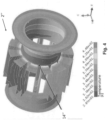
- FIG. 1 illustrates a conventional nozzle with a hot region, derived from a computer model, on an outside of the nozzle.
- the cooling water includes impurities, whereby the combination of the micro-boiling and impurities in the water lead to corrosive attack of the copper.
- even high purity distilled and deionized water will eventually cause corrosion over time.
- the thermal heat transfer coefficient of the copper changes, which alters the thermal state of the plasma nozzle and, therefore, alters the plasma arc.
- a nozzle designed or constructed to reduce or eliminate the corrosion of the copper nozzle at the water interfaces in order to promote arc voltage stability and increase usable hardware life.
- Embodiments of the invention are directed to a nozzle for a thermal spray gun according to independent claim 1.
- the nozzle body can be copper.
- the nozzle can also include a liner arranged on at least a part of an interior surface of the central bore.
- the water coolable surface coating may include nickel, chromium, cadmium, vanadium, platinum, gold, silver, tungsten, or molybdenum.
- the water coolable surface coating can prevent corrosion due to micro-boiling of the cooling water at the water coolable surface.
- the water coolable surface coating has a coating thickness of between about 2.54 ⁇ m (0.0001") and about 25.4 ⁇ m (0.001"). In other embodiments, the water coolable surface coating can have a coating thickness of between about 12.7 ⁇ m (0.0005") and about 25.4 ⁇ m (0.001").
- the water coolable surface coating can have a coating thickness to avoid limiting heat flow from the nozzle body to the cooling water.
- the water coolable surface coating can be formed from a material applicable by one of chemical bath deposition, chemical vapor deposition, physical vapor deposition, plasma spray physical vapor deposition, electron discharge physical vapor deposition, or any variants or hybrids thereof.
- the at least a portion of the exterior surface can include a surface at which a surface temperature of the water cooled surface is expected to approach or exceed a local boiling temperature of the cooling water.
- the at least a portion of the exterior surface may include an entirety of the exterior surface contactable by the cooling water.
- Embodiments of the invention are directed to a thermal spray gun according to independent claim 9..
- the nozzle body may include copper.
- the nozzle can further include a liner arranged on at least a part of an interior surface of the central bore.
- the water coolable surface coating may include nickel, chromium, cadmium, vanadium, platinum, gold, silver, tungsten, or molybdenum.
- the coating may be formed by a material to prevent corrosion due to micro-boiling of the cooling water at the at least portions of the exterior surface.
- the coating has a thickness of between about 2.54 ⁇ m (0.0001") and about 25.4 ⁇ m (0.001"). In further embodiments, the coating can have a thickness of between about 12.7 ⁇ m (0.0005") and about 25.4 ⁇ m (0.001 ").
- Embodiments of the invention are directed to a method of forming a nozzle for a thermal spray gun includes coating at least portions of an exterior surface of a nozzle body with at least one of nickel, chromium, cadmium, vanadium, platinum, gold, silver, tungsten, or molybdenum.
- the coating can be applied by one of chemical bath deposition, chemical vapor deposition, physical vapor deposition, plasma spray physical vapor deposition, electron discharge physical vapor deposition, or any variants or hybrids thereof.
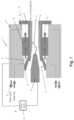
- Figure 1 illustrates a front gun body 1 of a conventional plasma spray gun that includes a conventional plasma nozzle 2, a cathode 3 and a water cooling system 4.
- the conventional plasma spray gun can be, e.g., an F4MB-XI, or 9MB plasma gun manufactured by Oerlikon Metco (US) Inc. of Westbury, New York, an SG100 plasma gun manufactured by Progressive Technologies, or any typical conventional plasma gun exemplified by having a single cathode and a non-cascading anode/plasma arc channel.
- Plasma nozzle 2 can be made of a material with high heat transfer characteristics, e.g., from copper only or a copper nozzle can include a lining, e.g.
- a plasma is formed in plasma nozzle 2 by passing a current through a gas, typically, e.g., Ar, N 2 , He, or H 2 and mixtures thereof, creating a plasma arc 7.
- a gas typically, e.g., Ar, N 2 , He, or H 2 and mixtures thereof.
- cathode 3 is connected to the negative side of a dc power source (not shown) and nozzle 2, acting as an anode, is connected to the positive side of the dc power source.
- Plasma nozzle 2 includes a conical bore 5 in which cathode 3 is accommodated and a cylindrical bore 6 in which plasma arc 7 preferably attaches.
- plasma arc 7 may travel some distance down cylindrical bore 6 before attaching to the nozzle wall, which produces the highest plasma voltage.
- the initial attachment point for plasma arc 7 can be between the first one-third and one-half of cylindrical bore 6 downstream of conical bore 5, and the plasma voltage at the wall is preferably greater than 70V at predetermined operating parameters.
- Other parameters will result in different voltages depending upon gasses, hardware geometry, current, etc.
- plasma arc 7 becomes attracted further upstream until plasma arc 7 eventually attaches to the wall of conical bore 5, at which time the voltage drop is large enough to require nozzle 2 to be replaced.
- the wall within conical bore 5 is an undesired area of plasma arc attachment, where the plasma voltage is less than 70V at a given operating parameter.
- other parameters will result in different voltages depending upon gasses, hardware geometry, current, etc.
- fins 12 To cool the nozzle, radially extending from an outer peripheral surface of nozzle 2 is a plurality of fins 12. Fins 12 also extend in a longitudinal direction of nozzle 2 to surround a point at which conical bore 5 and cylindrical bore 6 meet, as well as portions of conical bore 5, e.g., to surround about one-half of a length of conical bore 5, and cylindrical portion 6, e.g., to surround the arc attachment region. When a tungsten lining is provided, fins 12 can be arranged to extend, e.g., from a beginning of the lining forming a portion of the wall in conical bore 5 to an end of predetermined arc attachment region surrounding cylindrical bore 6.
- water cooling system 4 is arranged to cool the exterior of nozzle 2 with circulating water.
- Water cooling system 4 includes a water cooling path 8 that enters from a rear of the gun body, is directed around the outer perimeter of nozzle 2 and through cooling fins 12 before exiting.
- water cooling system 4 has at least one water inlet port 9 to supply cooling water from a supply to the outer periphery of nozzle 2 and has at least one water outlet port 10 through which the water cooling the outer periphery of nozzle 2 exits and is returned to the supply.
- Water inlet port 9 supplies cooling water to contact an outer peripheral surface 11 of nozzle 2 surrounding a part of conical bore 5.
- the cooling water is then guided through fins 12 to contact and cool the periphery in which fins 12 are located and then into an area to contact and cool the peripheral surface 13 surrounding a part of cylindrical bore 6.
- the circulating cooling water can be guided through the water cooling path 8 in an opposite direction, or other suitable manners of conveying the cooling water to the surfaces of the nozzle 2 to be cooled can be employed.
- Fig. 2 depicts a boiling pattern 14 on outer peripheral surface 16 of nozzle 2 due to micro-boiling and Fig. 3 shows an actual nozzle 2' with an actual boiling pattern 14' on the outer peripheral surface 16' due to micro-boiling, which generally corresponds to that shown in Fig. 2 .
- Fig. 3 shows an actual nozzle 2' with an actual boiling pattern 14' on the outer peripheral surface 16' due to micro-boiling, which generally corresponds to that shown in Fig. 2 .
- FIG. 4 illustrates a computer modeled boiling pattern 14" located on an outer peripheral surface of a modeled nozzle 2" due to micro-boiling at about 400K.
- Boiling patterns 14, 14' at 400K due to micro-boiling in Figs. 2 and 3 corresponds to boiling pattern 14" on modeled nozzle 2" depicted in Fig. 4 .
- the micro-boiling of the cooling water on the surface of nozzle 2, 2' in the region of boiling pattern 14, 14' in combination with impurities in the cooling water can lead to a corrosive attack of the exposed nozzle material, e.g., copper, in the region of boiling pattern 14, 14'.
- the thermal heat transfer coefficient of the material changes, thereby altering the thermal state of the nozzle 2, 2'. Consequently, the plasma arc will likewise be altered due to this corrosion. More particularly, testing has shown the altered thermal state of nozzle 2, 2' can lead to de-stabilization of the plasma arc voltage and this instability can promote arc voltage decay. This instability can also result in changes of energy state per unit time, which can thereby alter the process at the instantaneous level, be it thermal spray or chemical processing.
- the best alternative material found is tungsten, but even this material is best suited only as a lining of the bore of a copper plasma nozzle bore.
- Other high melting temperature materials, such as Tungsten alloy or Molybdenum, as described in U.S. Patent Application Publication No. 2013/0076631 also best suited as a lining rather than for an entire nozzle.
- the use of lining materials other than copper works best when the lining conforms to a thin layer in accordance with U.S. Patent Application Publication No. 2013/0076610 .
- surfaces of nozzle 2, and preferably all surfaces of nozzle 2, that are to be exposed to the cooling water are plated to protect the copper material from chemical interaction with the cooling water. It can be particularly advantageous to plate surfaces of nozzle 2 where a surface temperature of the water cooled surface approaches or exceeds a local boiling temperature of the cooling water. Of course it is also advantageous to plate other exterior surfaces of nozzle 2. However, the bore of nozzle 2 where the plasma arc resides should preferably not be plated, as the temperatures generated within this bore would melt the plating material and, consequently, the melted plating material would be ejected from the nozzle.
- the plating can be applied to nozzle 2 by, e.g., chemical bath deposition (electrolysis), chemical vapor deposition (CVD), physical vapor deposition (PVD), plasma spray physical vapor deposition (PSPVD), electron discharge physical vapor deposition (EDPVD), or any variants or hybrids of CVD, PVD, PSPVD, or EDPVD.
- chemical bath deposition or electrolysis is the preferred plating method.
- any method that can apply a sufficiently thin layer of a corrosion resistant pure metal or metallic alloy is viable.
- the plating material for providing the desired corrosion protection can preferably be a pure metal, e.g., nickel, chromium, cadmium, vanadium, platinum, gold, silver, tungsten, and molybdenum. Due to its low cost, ease of application and common availability, nickel is the preferred plating material. Moreover, metal alloys that are corrosion resistant can also be considered as a plating material. However, as metal alloys have a considerably lower thermal conductivity than the above-mentioned pure metals, it is to be understood that a plating thickness for a protective layer formed by such metal alloys should be thin enough to avoid limiting heat flow. Further, inert ceramic coatings are generally not considered viable solutions as a plating material because the thermal resistance typically associated with these ceramics is essentially the same as that of the by-products of the corroding copper.
- the plating merely needs to be thick enough to afford protection of the water cooled surface from corrosive attack for a reasonable amount of time.
- a plating thickness of at least 0.0001" (2.54 ⁇ m) nickel is acceptable to protect the nozzle material, but a somewhat thicker plating thickness may be preferred.
- a thicker plating thickness can be applied onto the nozzle.
- the plating material has a lower thermal conductivity than the copper in the nozzle, as the plating thickness increases, heat transfer properties of the plated nozzle will decrease, which can result in thermal damage to the nozzle bore.
- a plating thickness of about 0.001" (25.4 ⁇ m) nickel may be preferable, and a coating thickness of about 0.0005" (12.7 ⁇ m) nickel may be most preferred.
- plating thicknesses for these other pure metals would be preferably thinner than the noted nickel plating thicknesses.
- a test article was fabricated by taking a standard thermal spray plasma gun nozzle, e.g., a nozzle corresponding in construction to nozzle 2, and plating a roughly 25.4 ⁇ m (0.001"). thick layer of nickel using electrolysis.
- the nickel plating is applied to the exterior surface only, as plating or coating the interior of the nozzle bore has been found to be detrimental to nozzle performance.
- the plated nozzle was assembled into an F4 plasma gun manufactured by Oerlikon Metco (US) Inc., Westbury, NY and operated for a total of 30 hours, i.e., until the end of hardware life was reached based on a 3 volt drop.
- the system used contained water quality typical for operating plasma guns. An inspection of the plated nozzle at the end of hardware life found only some very minor affects from chemical precipitate forming in the areas of microboiling, which when wiped off revealed the original unaltered and shiny nickel coated surface.
- a second nozzle with identical plating was similarly tested for 30 hours with similar results.
- the water was replaced with fresh clean distilled and deionized water with a conductivity of less than 1 micro siemens ( ⁇ S).
- ⁇ S micro siemens
- the copper was assumed a result of copper ions being removed from other copper bearing surfaces inside the gun by the water and plating onto the nickel. The addition of this thin copper layer would not impair heat flow as it is too thin even if it underwent oxidation to block heat transfer to the water to any significant level.
- the plated nozzles exhibited better voltage stability during the entire time of the test as compared to the standard, i.e., unplated, nozzle while also able to resist an eventual decay in average voltage.
- the plating of the nozzle results in a nozzle that will last longer and provide more stable plasma arc performance for the life of the nozzle.
Landscapes
- Chemical & Material Sciences (AREA)
- Engineering & Computer Science (AREA)
- Physics & Mathematics (AREA)
- Plasma & Fusion (AREA)
- Materials Engineering (AREA)
- Chemical Kinetics & Catalysis (AREA)
- Mechanical Engineering (AREA)
- Metallurgy (AREA)
- Organic Chemistry (AREA)
- Electromagnetism (AREA)
- Coating By Spraying Or Casting (AREA)
- Plasma Technology (AREA)
- Arc Welding In General (AREA)
- Nozzles (AREA)
- Other Surface Treatments For Metallic Materials (AREA)
Description
- Plasma guns are used in various applications from thermal spray to plasma generators, e.g., to incinerate dangerous materials. Conventional plasma gun nozzles (anodes) used in thermal spray applications have a limited life. In use, the plasma voltage is maintained in a predefined range for proper operation. However, as the plasma arc is generated by the plasma gun, the bore of the nozzle is exposed to extremely high temperatures (> 12,000°K). To prevent melting of the nozzle wall, cooling water is circulated through the plasma gun to the anode and cathode.
- During operation of the plasma gun, the circulating cooling water will experience micro-boiling along the surface of the nozzle, which causes formation of bubbles at the water/nozzle inside interface surface. Despite the circulating cooling water, hot regions arise on the nozzle.
Figure 1 illustrates a conventional nozzle with a hot region, derived from a computer model, on an outside of the nozzle. Often the cooling water includes impurities, whereby the combination of the micro-boiling and impurities in the water lead to corrosive attack of the copper. Moreover, even high purity distilled and deionized water will eventually cause corrosion over time. As the copper corrodes, the thermal heat transfer coefficient of the copper changes, which alters the thermal state of the plasma nozzle and, therefore, alters the plasma arc. In this regard, testing has shown this change in thermal state leads to de-stabilization of the plasma arc voltage and this instability promotes arc voltage decay. This instability also results in changes of energy state per unit time, which can alter the process at the instantaneous level be it thermal spray or chemical processing. - At the end of its lifetime of use, corrosion can be found on exterior surfaces of a copper nozzle. As the copper corrodes, the thermal heat transfer coefficient of the copper changes, which alters the thermal state of the plasma nozzle and, therefore, alters the plasma arc. In testing, the inventor has found this change in thermal state leads to de-stabilization of the plasma arc voltage and this instability promotes arc voltage decay. This instability has also been found to result in changes of energy state per unit time, which can alter the process at the instantaneous level be it thermal spray or chemical processing. Nozzles for thermal spray guns with a nozzle body having a central bore and an exterior surface structured for insertion into a thermal spray gun are already disclosed in
WO 2014/120358 A1 . Corrosion-preventive coatings for plasma gas supply means are already disclosed inUS 2002/134766 A1 and a plasma arc welding torch comprising a nozzle having a coating on an exterior surface is already known fromJP H09 19771 A - What is needed is a nozzle designed or constructed to reduce or eliminate the corrosion of the copper nozzle at the water interfaces in order to promote arc voltage stability and increase usable hardware life.
- Embodiments of the invention are directed to a nozzle for a thermal spray gun according to independent claim 1.
- According to embodiments, the nozzle body can be copper. The nozzle can also include a liner arranged on at least a part of an interior surface of the central bore. Further, the water coolable surface coating may include nickel, chromium, cadmium, vanadium, platinum, gold, silver, tungsten, or molybdenum.
- In accordance with other embodiments, the water coolable surface coating can prevent corrosion due to micro-boiling of the cooling water at the water coolable surface.
- According to the invention, the water coolable surface coating has a coating thickness of between about 2.54 µm (0.0001") and about 25.4 µm (0.001"). In other embodiments, the water coolable surface coating can have a coating thickness of between about 12.7 µm (0.0005") and about 25.4 µm (0.001").
- In still other embodiments, the water coolable surface coating can have a coating thickness to avoid limiting heat flow from the nozzle body to the cooling water.
- Moreover, the water coolable surface coating can be formed from a material applicable by one of chemical bath deposition, chemical vapor deposition, physical vapor deposition, plasma spray physical vapor deposition, electron discharge physical vapor deposition, or any variants or hybrids thereof.
- According to other embodiments, the at least a portion of the exterior surface can include a surface at which a surface temperature of the water cooled surface is expected to approach or exceed a local boiling temperature of the cooling water.
- In further embodiments, the at least a portion of the exterior surface may include an entirety of the exterior surface contactable by the cooling water.
- Embodiments of the invention are directed to a thermal spray gun according to independent claim 9..
- According to embodiments, the nozzle body may include copper. In other embodiments, the nozzle can further include a liner arranged on at least a part of an interior surface of the central bore. Further, the water coolable surface coating may include nickel, chromium, cadmium, vanadium, platinum, gold, silver, tungsten, or molybdenum.
- In accordance with embodiments, the coating may be formed by a material to prevent corrosion due to micro-boiling of the cooling water at the at least portions of the exterior surface.
- The coating has a thickness of between about 2.54 µm (0.0001") and about 25.4 µm (0.001"). In further embodiments, the coating can have a thickness of between about 12.7 µm (0.0005") and about 25.4 µm (0.001 ").
- Embodiments of the invention are directed to a method of forming a nozzle for a thermal spray gun includes coating at least portions of an exterior surface of a nozzle body with at least one of nickel, chromium, cadmium, vanadium, platinum, gold, silver, tungsten, or molybdenum.
- In accordance with still yet other embodiments, the coating can be applied by one of chemical bath deposition, chemical vapor deposition, physical vapor deposition, plasma spray physical vapor deposition, electron discharge physical vapor deposition, or any variants or hybrids thereof.
- Other exemplary embodiments and advantages of the present invention may be ascertained by reviewing the present disclosure and the accompanying drawing.
- The present invention is further described in the detailed description which follows, in reference to the noted plurality of drawings by way of non-limiting examples of exemplary embodiments of the present invention, in which like reference numerals represent similar parts throughout the several views of the drawings, and wherein:
-
Fig. 1 illustrates a conventional thermal spray gun; -
Fig. 2 illustrates a nozzle for the thermal spray gun depicted inFig. 1 with a boiling pattern; -
Fig. 3 shows a nozzle with a boiling pattern corresponding to the computer model ofFig. 2 ; and -
Fig. 4 graphically illustrates a computer model of the nozzle of the thermal spray gun shown inFig. 1 , to which the boiling patterns ofFigs. 2 and3 correspond. -
Figure 1 illustrates a front gun body 1 of a conventional plasma spray gun that includes aconventional plasma nozzle 2, a cathode 3 and a water cooling system 4. The conventional plasma spray gun can be, e.g., an F4MB-XI, or 9MB plasma gun manufactured by Oerlikon Metco (US) Inc. of Westbury, New York, an SG100 plasma gun manufactured by Progressive Technologies, or any typical conventional plasma gun exemplified by having a single cathode and a non-cascading anode/plasma arc channel.Plasma nozzle 2 can be made of a material with high heat transfer characteristics, e.g., from copper only or a copper nozzle can include a lining, e.g. a tungsten lining, a molybdenum lining, a high Tungsten alloy lining, a silver lining or an iridium lining, to improve performance. A plasma is formed inplasma nozzle 2 by passing a current through a gas, typically, e.g., Ar, N2, He, or H2 and mixtures thereof, creating aplasma arc 7. To create the current, cathode 3 is connected to the negative side of a dc power source (not shown) andnozzle 2, acting as an anode, is connected to the positive side of the dc power source.Plasma nozzle 2 includes aconical bore 5 in which cathode 3 is accommodated and a cylindrical bore 6 in whichplasma arc 7 preferably attaches. - In initial operation,
plasma arc 7 may travel some distance down cylindrical bore 6 before attaching to the nozzle wall, which produces the highest plasma voltage. By way of non-limiting example, the initial attachment point forplasma arc 7 can be between the first one-third and one-half of cylindrical bore 6 downstream ofconical bore 5, and the plasma voltage at the wall is preferably greater than 70V at predetermined operating parameters. Other parameters will result in different voltages depending upon gasses, hardware geometry, current, etc. As the surface ofnozzle wall 2 wears and deteriorates,plasma arc 7 becomes attracted further upstream untilplasma arc 7 eventually attaches to the wall ofconical bore 5, at which time the voltage drop is large enough to requirenozzle 2 to be replaced. The wall withinconical bore 5 is an undesired area of plasma arc attachment, where the plasma voltage is less than 70V at a given operating parameter. Again, other parameters will result in different voltages depending upon gasses, hardware geometry, current, etc. - To cool the nozzle, radially extending from an outer peripheral surface of
nozzle 2 is a plurality offins 12. Fins 12 also extend in a longitudinal direction ofnozzle 2 to surround a point at whichconical bore 5 and cylindrical bore 6 meet, as well as portions ofconical bore 5, e.g., to surround about one-half of a length ofconical bore 5, and cylindrical portion 6, e.g., to surround the arc attachment region. When a tungsten lining is provided,fins 12 can be arranged to extend, e.g., from a beginning of the lining forming a portion of the wall inconical bore 5 to an end of predetermined arc attachment region surrounding cylindrical bore 6. - In operation, extremely high temperatures can be produced within bore 6 of
nozzle 2, e.g., greater than 12,000°K, which can result in extremely high peak average wall temperatures, e.g., 700 - 800°K in nozzle bore 6. To prevent the extreme temperatures from meltingnozzle 2, water cooling system 4 is arranged to cool the exterior ofnozzle 2 with circulating water. Water cooling system 4 includes a water cooling path 8 that enters from a rear of the gun body, is directed around the outer perimeter ofnozzle 2 and throughcooling fins 12 before exiting. In the illustrated embodiment, water cooling system 4 has at least one water inlet port 9 to supply cooling water from a supply to the outer periphery ofnozzle 2 and has at least onewater outlet port 10 through which the water cooling the outer periphery ofnozzle 2 exits and is returned to the supply. Water inlet port 9 supplies cooling water to contact an outerperipheral surface 11 ofnozzle 2 surrounding a part ofconical bore 5. The cooling water is then guided throughfins 12 to contact and cool the periphery in whichfins 12 are located and then into an area to contact and cool theperipheral surface 13 surrounding a part of cylindrical bore 6. It is also understood that the circulating cooling water can be guided through the water cooling path 8 in an opposite direction, or other suitable manners of conveying the cooling water to the surfaces of thenozzle 2 to be cooled can be employed. - During operation of the thermal spray gun, the circulating cooling water in water cooling system 4 is under pressure. Consequently, a phenomenon known as micro-boiling can occur along a surface of
nozzle 2 as tiny steam bubbles begin forming at the outer peripheral surface ofnozzle 2 contacting the cooling water, e.g., outerperipheral surface 11, the outer peripheral surface betweenfins 12 and outerperipheral surface 16 surrounding part of cylindrical bore 6.Fig. 2 depicts a boilingpattern 14 on outerperipheral surface 16 ofnozzle 2 due to micro-boiling andFig. 3 shows an actual nozzle 2' with an actual boiling pattern 14' on the outer peripheral surface 16' due to micro-boiling, which generally corresponds to that shown inFig. 2 .Fig. 4 illustrates a computer modeled boilingpattern 14" located on an outer peripheral surface of a modelednozzle 2" due to micro-boiling at about 400K. Boilingpatterns 14, 14' at 400K due to micro-boiling inFigs. 2 and3 corresponds to boilingpattern 14" on modelednozzle 2" depicted inFig. 4 . Moreover, it has been found that the micro-boiling of the cooling water on the surface ofnozzle 2, 2' in the region of boilingpattern 14, 14' in combination with impurities in the cooling water can lead to a corrosive attack of the exposed nozzle material, e.g., copper, in the region of boilingpattern 14, 14'. This is because the steam resulting from the micro-boiling is highly reactive so that any contaminants in the cooling water will attack the copper nozzle material. It has further been found that, even if the cooling water is a high purity distilled and deionized cooling water, corrosion will still eventually occur on the water cooled surface ofnozzle 2, 2' because all contaminants cannot be removed from the water and the ultra-pure water itself will naturally attack the copper directly. - As the water cooled material surface, e.g., copper, in the region of boiling
pattern 14, 14' corrodes, the thermal heat transfer coefficient of the material changes, thereby altering the thermal state of thenozzle 2, 2'. Consequently, the plasma arc will likewise be altered due to this corrosion. More particularly, testing has shown the altered thermal state ofnozzle 2, 2' can lead to de-stabilization of the plasma arc voltage and this instability can promote arc voltage decay. This instability can also result in changes of energy state per unit time, which can thereby alter the process at the instantaneous level, be it thermal spray or chemical processing. - While copper is a preferred material in constructing plasma gun nozzles because of its high thermal conductivity and its high electrical conductivity, alternative materials have been tested to construct the
entire nozzle 2 with varying results, i.e., from adequate performance to failure resulting in a complete melting of the nozzle. The best alternative material found is tungsten, but even this material is best suited only as a lining of the bore of a copper plasma nozzle bore. Other high melting temperature materials, such as Tungsten alloy or Molybdenum, as described inU.S. Patent Application Publication No. 2013/0076631 also best suited as a lining rather than for an entire nozzle. Moreover, the use of lining materials other than copper works best when the lining conforms to a thin layer in accordance withU.S. Patent Application Publication No. 2013/0076610 . - In embodiments, surfaces of
nozzle 2, and preferably all surfaces ofnozzle 2, that are to be exposed to the cooling water are plated to protect the copper material from chemical interaction with the cooling water. It can be particularly advantageous to plate surfaces ofnozzle 2 where a surface temperature of the water cooled surface approaches or exceeds a local boiling temperature of the cooling water. Of course it is also advantageous to plate other exterior surfaces ofnozzle 2. However, the bore ofnozzle 2 where the plasma arc resides should preferably not be plated, as the temperatures generated within this bore would melt the plating material and, consequently, the melted plating material would be ejected from the nozzle. - By way of non-limiting example, the plating can be applied to
nozzle 2 by, e.g., chemical bath deposition (electrolysis), chemical vapor deposition (CVD), physical vapor deposition (PVD), plasma spray physical vapor deposition (PSPVD), electron discharge physical vapor deposition (EDPVD), or any variants or hybrids of CVD, PVD, PSPVD, or EDPVD. In particular, as it is the easiest, most common and least costly method, the chemical bath deposition or electrolysis is the preferred plating method. Of course, any method that can apply a sufficiently thin layer of a corrosion resistant pure metal or metallic alloy is viable. - The plating material for providing the desired corrosion protection can preferably be a pure metal, e.g., nickel, chromium, cadmium, vanadium, platinum, gold, silver, tungsten, and molybdenum. Due to its low cost, ease of application and common availability, nickel is the preferred plating material. Moreover, metal alloys that are corrosion resistant can also be considered as a plating material. However, as metal alloys have a considerably lower thermal conductivity than the above-mentioned pure metals, it is to be understood that a plating thickness for a protective layer formed by such metal alloys should be thin enough to avoid limiting heat flow. Further, inert ceramic coatings are generally not considered viable solutions as a plating material because the thermal resistance typically associated with these ceramics is essentially the same as that of the by-products of the corroding copper.
- According to embodiments, the plating merely needs to be thick enough to afford protection of the water cooled surface from corrosive attack for a reasonable amount of time. By way of non-limiting example, a plating thickness of at least 0.0001" (2.54 µm) nickel is acceptable to protect the nozzle material, but a somewhat thicker plating thickness may be preferred. In this regard, as long as the plating does not interfere with the tolerance and fit of the nozzle inside the thermal spray gun, a thicker plating thickness can be applied onto the nozzle. Of course, as the plating material has a lower thermal conductivity than the copper in the nozzle, as the plating thickness increases, heat transfer properties of the plated nozzle will decrease, which can result in thermal damage to the nozzle bore. Therefore, by way of further non-limiting example, a plating thickness of about 0.001" (25.4 µm) nickel may be preferable, and a coating thickness of about 0.0005" (12.7 µm) nickel may be most preferred. Moreover, as the other noted pure metals have lower thermal conductivity than nickel, plating thicknesses for these other pure metals would be preferably thinner than the noted nickel plating thicknesses.
- In accordance with embodiments, a test article was fabricated by taking a standard thermal spray plasma gun nozzle, e.g., a nozzle corresponding in construction to
nozzle 2, and plating a roughly 25.4 µm (0.001"). thick layer of nickel using electrolysis. In particular, the nickel plating is applied to the exterior surface only, as plating or coating the interior of the nozzle bore has been found to be detrimental to nozzle performance. The plated nozzle was assembled into an F4 plasma gun manufactured by Oerlikon Metco (US) Inc., Westbury, NY and operated for a total of 30 hours, i.e., until the end of hardware life was reached based on a 3 volt drop. The system used contained water quality typical for operating plasma guns. An inspection of the plated nozzle at the end of hardware life found only some very minor affects from chemical precipitate forming in the areas of microboiling, which when wiped off revealed the original unaltered and shiny nickel coated surface. - A second nozzle with identical plating was similarly tested for 30 hours with similar results. In this test the water was replaced with fresh clean distilled and deionized water with a conductivity of less than 1 micro siemens (µS). In this case, there was observed a very thin layer of copper on the nozzle water channels with no precipitate buildup from microboiling. The copper was assumed a result of copper ions being removed from other copper bearing surfaces inside the gun by the water and plating onto the nickel. The addition of this thin copper layer would not impair heat flow as it is too thin even if it underwent oxidation to block heat transfer to the water to any significant level.
- Moreover, an inspection of a standard (unplated) nozzle, which was operated for 30 hours at the same operating conditions as the two tested plated nozzle, finds darkening of the copper in areas where the nozzle is subjected to the highest temperatures at the water interface. In these regions, the copper is reacting with dissolved oxygen in the water to form copper oxide, which inhibits heat flow from the nozzle to the water. Conversely, visual inspection of the tested plated nozzle reveals little discoloration, and the discoloration that was found was determined to be from a small buildup of precipitate due to water impurity in the region of micro-boiling and not corrosion.
- Moreover, in operation, the plated nozzles exhibited better voltage stability during the entire time of the test as compared to the standard, i.e., unplated, nozzle while also able to resist an eventual decay in average voltage. Thus, the plating of the nozzle results in a nozzle that will last longer and provide more stable plasma arc performance for the life of the nozzle.
Claims (14)
- A nozzle for a thermal spray gun comprising:a nozzle body having a central bore (5) and an exterior surface structured for insertion into a thermal spray gun;characterized in thatthe nozzle (2) further comprises a water coolable surface coating applied onto at least a portion of the exterior surface,wherein the water coolable surface coating is structured to protect the exterior surface from a chemical interaction with cooling water guided through the thermal spray gun and the water coolable surface coating has a coating thickness of between about 2.54 µm (0.0001") and about 25.4 µm (0.001"),and wherein the nozzle (2) comprises a plurality of cooling fins (12) extending radially from the exterior surface.
- The nozzle according to claim 1, wherein the nozzle body is copper.
- The nozzle according to claim 2, further comprising a liner arranged on at least a part of an interior surface of the central bore (5).
- The nozzle according to claim 2, wherein the water coolable surface coating comprises nickel, chromium, cadmium, vanadium, platinum, gold, silver, tungsten, or molybdenum.
- The nozzle according to claim 1, wherein the water coolable surface coating prevents corrosion due to micro-boiling of the cooling water at the water coolable surface.
- The nozzle according to claim 1, wherein the water coolable surface coating has a coating thickness of between about 12.7 µm (0.0005") and about 25.4 µm (0.001").
- The nozzle according to claim 1, wherein the water coolable surface coating is formed from a material applicable by one of chemical bath deposition, chemical vapor deposition, physical vapor deposition, plasma spray physical vapor deposition, electron discharge physical vapor deposition.
- The nozzle according to claim 1, wherein the at least a portion of the exterior surface comprises an entirety of the exterior surface contactable by the cooling water.
- A thermal spray gun comprising:an insertable nozzle (2) comprising a nozzle body having a central bore (5) and an exterior surface structured for insertion into the thermal spray gun;characterized in thatthe nozzle (2) further comprises a water coolable surface coating applied onto at least a portion of the exterior surface,wherein the water coolable surface coating is structured to protect the exterior surface from a chemical interaction with cooling water guided through the thermal spray gun and the water coolable surface coating has a coating thickness of between about 2.54 µm (0.0001") and about 25.4 µm (0.001"); anda water cooling system (4) structured and arranged to guide cooling water onto the at least portions of the exterior surface,and wherein the nozzle (2) comprises a plurality of cooling fins (12) extending radially from the exterior surface.
- The thermal spray gun according to claim 9, wherein the nozzle body comprises copper, in particular the nozzle further comprising a liner arranged on at least a part of an interior surface of the central bore (5).
- The thermal spray gun according to claim 9, wherein the water coolable surface coating comprises nickel, chromium, cadmium, vanadium, platinum, gold, silver, tungsten, or molybdenum, or the coating is formed by a material to prevent corrosion due to micro-boiling of the cooling water at the at least portions of the exterior surface
- The thermal spray gun according to claim 9, wherein the coating has a thickness of between about 12.7 µm (0.0005") and about 25.4 µm (0.001").
- A method of forming a nozzle (2) for a thermal spray gun according to one of the claims 1 to 8 comprising:coating at least portions of the exterior surface of the nozzle body with at least one of nickel, chromium, cadmium, vanadium, platinum, gold, silver, tungsten, ormolybdenum.
- The method according to claim 13, wherein the coating is applied by one of chemical bath deposition, chemical vapor deposition, physical vapor deposition, plasma spray physical vapor deposition, electron discharge physical vapor deposition.
Applications Claiming Priority (2)
| Application Number | Priority Date | Filing Date | Title |
|---|---|---|---|
| US14/568,833 US11511298B2 (en) | 2014-12-12 | 2014-12-12 | Corrosion protection for plasma gun nozzles and method of protecting gun nozzles |
| PCT/US2015/064465 WO2016094388A1 (en) | 2014-12-12 | 2015-12-08 | Corrosion protection for plasma gun nozzles and method of protecting gun nozzles |
Publications (3)
| Publication Number | Publication Date |
|---|---|
| EP3230006A1 EP3230006A1 (en) | 2017-10-18 |
| EP3230006A4 EP3230006A4 (en) | 2018-08-01 |
| EP3230006B1 true EP3230006B1 (en) | 2023-06-07 |
Family
ID=56108051
Family Applications (1)
| Application Number | Title | Priority Date | Filing Date |
|---|---|---|---|
| EP15868541.2A Active EP3230006B1 (en) | 2014-12-12 | 2015-12-08 | Corrosion protection for plasma gun nozzles and method of protecting gun nozzles |
Country Status (8)
| Country | Link |
|---|---|
| US (1) | US11511298B2 (en) |
| EP (1) | EP3230006B1 (en) |
| JP (1) | JP6775504B2 (en) |
| CN (1) | CN107206534B (en) |
| CA (1) | CA2967992C (en) |
| ES (1) | ES2953288T3 (en) |
| PL (1) | PL3230006T3 (en) |
| WO (1) | WO2016094388A1 (en) |
Families Citing this family (12)
| Publication number | Priority date | Publication date | Assignee | Title |
|---|---|---|---|---|
| USD889520S1 (en) * | 2017-03-16 | 2020-07-07 | Oerlikon Metco (Us) Inc. | Neutrode |
| JP7149954B2 (en) * | 2017-03-16 | 2022-10-07 | エリコン メテコ(ユーエス)インコーポレイテッド | Optimized cooling of neutrode stacks for plasma guns |
| RU2020129100A (en) * | 2018-02-20 | 2022-03-21 | ЭРЛИКОН МЕТКО (ЮЭс) ИНК. | SINGLE-ARC CASCADE LOW-PRESSURE PLASMA TORCH USING A NEUTRODE PACKAGE AS A METHOD OF PLASMA ARC CONTROL |
| ES2952997T3 (en) * | 2018-06-22 | 2023-11-07 | Molecular Plasma Group Sa | Improved method and apparatus for atmospheric pressure plasma jet coating deposition on a substrate |
| CN110536532A (en) * | 2019-09-05 | 2019-12-03 | 河北宝炬新材料科技有限公司 | A kind of arc plasma generator |
| US12484138B2 (en) | 2019-10-04 | 2025-11-25 | Kennametal Inc. | Coated nozzles for arc torches |
| CN113000233B (en) * | 2019-12-18 | 2022-09-02 | 中微半导体设备(上海)股份有限公司 | Plasma reactor and gas nozzle thereof |
| KR102183141B1 (en) * | 2020-04-07 | 2020-11-25 | 에너진(주) | Plasma Nozzle and Plasma Thermal Injector |
| EP3954801A1 (en) * | 2020-08-10 | 2022-02-16 | TI Automotive Engineering Centre (Heidelberg) GmbH | Multi-walled tube and method for producing multi-walled tubes |
| KR102491899B1 (en) * | 2021-03-08 | 2023-01-26 | (주)에이피아이 | Nozzle apparatus |
| CZ2021453A3 (en) * | 2021-09-24 | 2022-11-09 | Thermacut, K.S. | Nozzle for plasma torch and plasma torch |
| CN113915990A (en) * | 2021-11-26 | 2022-01-11 | 中船第九设计研究院工程有限公司 | Nozzle for hot drying of waste paint bucket |
Family Cites Families (27)
| Publication number | Priority date | Publication date | Assignee | Title |
|---|---|---|---|---|
| US4235943A (en) | 1979-02-22 | 1980-11-25 | United Technologies Corporation | Thermal spray apparatus and method |
| US4358053A (en) * | 1980-11-26 | 1982-11-09 | Metco, Inc. | Flame spraying device with rocket acceleration |
| JPS5873366A (en) | 1981-10-26 | 1983-05-02 | 日立化成工業株式会社 | Plastic forceps |
| JPS5873366U (en) * | 1981-11-13 | 1983-05-18 | 株式会社日立製作所 | Cooling water pipe for plasma spray equipment |
| JPS61166987A (en) | 1985-01-17 | 1986-07-28 | Hitachi Cable Ltd | Fin material for radiator |
| EP0194634A3 (en) | 1985-03-14 | 1987-11-19 | The Perkin-Elmer Corporation | Plasma gun nozzle with extended life |
| US4634611A (en) * | 1985-05-31 | 1987-01-06 | Cabot Corporation | Flame spray method and apparatus |
| US4818371A (en) * | 1987-06-05 | 1989-04-04 | Resource Technology Associates | Viscosity reduction by direct oxidative heating |
| US5014901A (en) * | 1989-06-26 | 1991-05-14 | Foster Wheeler Energy Corporation | Rotatable welding fixture and method for metal cladding tubular membrane panels |
| JP2640707B2 (en) | 1991-02-28 | 1997-08-13 | 株式会社小松製作所 | Plasma torch for cutting |
| US5135166A (en) * | 1991-05-08 | 1992-08-04 | Plasma-Technik Ag | High-velocity thermal spray apparatus |
| US5285967A (en) * | 1992-12-28 | 1994-02-15 | The Weidman Company, Inc. | High velocity thermal spray gun for spraying plastic coatings |
| JPH0919771A (en) | 1995-07-04 | 1997-01-21 | Sumitomo Metal Ind Ltd | Nozzle for plasma arc welding torch |
| TW469757B (en) | 1999-12-13 | 2001-12-21 | Nippon Steel Corp | A transferred plasma heating anode |
| JP3682192B2 (en) | 1999-12-13 | 2005-08-10 | 新日本製鐵株式会社 | Transition type plasma heating anode |
| JP2001316865A (en) | 2000-05-08 | 2001-11-16 | Mitsubishi Electric Corp | Corrosion-protected copper member and method of manufacturing the same |
| US20050131116A1 (en) * | 2002-07-12 | 2005-06-16 | Qun Sun | Process for dissolution of highly fluorinated ion-exchange polymers |
| JP4694227B2 (en) | 2005-03-11 | 2011-06-08 | 三島光産株式会社 | Continuous casting mold |
| US7342197B2 (en) * | 2005-09-30 | 2008-03-11 | Phoenix Solutions Co. | Plasma torch with corrosive protected collimator |
| JP2008157090A (en) | 2006-12-22 | 2008-07-10 | Toyota Motor Corp | Exhaust heat recovery device for internal combustion engine |
| US7972655B2 (en) | 2007-11-21 | 2011-07-05 | Enthone Inc. | Anti-tarnish coatings |
| US20130008708A1 (en) * | 2011-07-07 | 2013-01-10 | Burke Thomas F | Electrical shielding material composed of metallized aluminum monofilaments |
| BR112014015610A8 (en) | 2012-01-27 | 2017-07-04 | Sulzer Metco Us Inc | closed loop cooling of a plasma gun to extend hardware life |
| GB201219202D0 (en) | 2012-10-25 | 2012-12-12 | Oxford Nanosystems | Heat transfer surface coating |
| JP6469023B2 (en) | 2013-01-31 | 2019-02-13 | エリコン メテコ(ユーエス)インコーポレイテッド | Optimized thermal nozzle and method of using the same |
| JP6602204B2 (en) | 2013-01-31 | 2019-11-06 | エリコン メテコ(ユーエス)インコーポレイテッド | Long-life nozzle for thermal spray gun and its production and use |
| AU2013408315B2 (en) | 2013-12-19 | 2019-01-17 | Oerlikon Metco (Us) Inc. | Long-life plasma nozzle with liner |
-
2014
- 2014-12-12 US US14/568,833 patent/US11511298B2/en active Active
-
2015
- 2015-12-08 PL PL15868541.2T patent/PL3230006T3/en unknown
- 2015-12-08 ES ES15868541T patent/ES2953288T3/en active Active
- 2015-12-08 EP EP15868541.2A patent/EP3230006B1/en active Active
- 2015-12-08 CN CN201580064712.2A patent/CN107206534B/en active Active
- 2015-12-08 JP JP2017528583A patent/JP6775504B2/en active Active
- 2015-12-08 WO PCT/US2015/064465 patent/WO2016094388A1/en not_active Ceased
- 2015-12-08 CA CA2967992A patent/CA2967992C/en active Active
Also Published As
| Publication number | Publication date |
|---|---|
| US20160167063A1 (en) | 2016-06-16 |
| US11511298B2 (en) | 2022-11-29 |
| EP3230006A1 (en) | 2017-10-18 |
| PL3230006T3 (en) | 2023-10-09 |
| JP6775504B2 (en) | 2020-10-28 |
| CA2967992A1 (en) | 2016-06-16 |
| WO2016094388A1 (en) | 2016-06-16 |
| CA2967992C (en) | 2023-02-14 |
| ES2953288T3 (en) | 2023-11-10 |
| CN107206534B (en) | 2022-10-28 |
| CN107206534A (en) | 2017-09-26 |
| JP2018507316A (en) | 2018-03-15 |
| EP3230006A4 (en) | 2018-08-01 |
Similar Documents
| Publication | Publication Date | Title |
|---|---|---|
| CA2967992C (en) | Corrosion protection for plasma gun nozzles and method of protecting gun nozzles | |
| US8097828B2 (en) | Dielectric devices for a plasma arc torch | |
| CN105102168B (en) | Long-life nozzles for thermal spray guns and methods of making and using the same | |
| EP2952069B1 (en) | Optimized thermal nozzle and method of using same | |
| AU2006297859A1 (en) | Plasma torch with corrosive protected collimator | |
| EP3083064B1 (en) | Long-life plasma nozzle with liner | |
| US20160363222A1 (en) | Nitride Coated Piston Ring | |
| US20200045804A1 (en) | Protective nozzle cap, plasma arc torch comprising said protective nozzle cap, and use of the plasma arc torch | |
| KR20080082283A (en) | Plasma Spray Coating Method | |
| US9315888B2 (en) | Nozzle insert for thermal spray gun apparatus | |
| US9966234B2 (en) | Film forming device | |
| JP2018162520A (en) | Long-life plasma-nozzle subjected to lining | |
| TR2021014081Y (en) | CONTACT NOZZLE FOR GAS WELDING | |
| JP2012006110A (en) | Tool electrode for diesinking edm | |
| JPH07290318A (en) | Electric discharge machine |
Legal Events
| Date | Code | Title | Description |
|---|---|---|---|
| STAA | Information on the status of an ep patent application or granted ep patent |
Free format text: STATUS: THE INTERNATIONAL PUBLICATION HAS BEEN MADE |
|
| PUAI | Public reference made under article 153(3) epc to a published international application that has entered the european phase |
Free format text: ORIGINAL CODE: 0009012 |
|
| STAA | Information on the status of an ep patent application or granted ep patent |
Free format text: STATUS: REQUEST FOR EXAMINATION WAS MADE |
|
| 17P | Request for examination filed |
Effective date: 20170712 |
|
| AK | Designated contracting states |
Kind code of ref document: A1 Designated state(s): AL AT BE BG CH CY CZ DE DK EE ES FI FR GB GR HR HU IE IS IT LI LT LU LV MC MK MT NL NO PL PT RO RS SE SI SK SM TR |
|
| AX | Request for extension of the european patent |
Extension state: BA ME |
|
| DAV | Request for validation of the european patent (deleted) | ||
| DAX | Request for extension of the european patent (deleted) | ||
| A4 | Supplementary search report drawn up and despatched |
Effective date: 20180704 |
|
| RIC1 | Information provided on ipc code assigned before grant |
Ipc: B23K 10/02 20060101ALI20180628BHEP Ipc: B05B 15/18 20180101AFI20180628BHEP Ipc: C23C 4/134 20160101ALI20180628BHEP Ipc: H05H 1/34 20060101ALI20180628BHEP Ipc: B05B 7/22 20060101ALI20180628BHEP Ipc: H05H 1/28 20060101ALI20180628BHEP |
|
| STAA | Information on the status of an ep patent application or granted ep patent |
Free format text: STATUS: EXAMINATION IS IN PROGRESS |
|
| 17Q | First examination report despatched |
Effective date: 20200623 |
|
| GRAP | Despatch of communication of intention to grant a patent |
Free format text: ORIGINAL CODE: EPIDOSNIGR1 |
|
| STAA | Information on the status of an ep patent application or granted ep patent |
Free format text: STATUS: GRANT OF PATENT IS INTENDED |
|
| INTG | Intention to grant announced |
Effective date: 20230313 |
|
| GRAS | Grant fee paid |
Free format text: ORIGINAL CODE: EPIDOSNIGR3 |
|
| GRAA | (expected) grant |
Free format text: ORIGINAL CODE: 0009210 |
|
| STAA | Information on the status of an ep patent application or granted ep patent |
Free format text: STATUS: THE PATENT HAS BEEN GRANTED |
|
| AK | Designated contracting states |
Kind code of ref document: B1 Designated state(s): AL AT BE BG CH CY CZ DE DK EE ES FI FR GB GR HR HU IE IS IT LI LT LU LV MC MK MT NL NO PL PT RO RS SE SI SK SM TR |
|
| REG | Reference to a national code |
Ref country code: GB Ref legal event code: FG4D |
|
| REG | Reference to a national code |
Ref country code: CH Ref legal event code: EP Ref country code: AT Ref legal event code: REF Ref document number: 1573376 Country of ref document: AT Kind code of ref document: T Effective date: 20230615 |
|
| REG | Reference to a national code |
Ref country code: DE Ref legal event code: R096 Ref document number: 602015084054 Country of ref document: DE |
|
| REG | Reference to a national code |
Ref country code: SE Ref legal event code: TRGR |
|
| REG | Reference to a national code |
Ref country code: NL Ref legal event code: FP |
|
| REG | Reference to a national code |
Ref country code: LT Ref legal event code: MG9D |
|
| PG25 | Lapsed in a contracting state [announced via postgrant information from national office to epo] |
Ref country code: NO Free format text: LAPSE BECAUSE OF FAILURE TO SUBMIT A TRANSLATION OF THE DESCRIPTION OR TO PAY THE FEE WITHIN THE PRESCRIBED TIME-LIMIT Effective date: 20230907 |
|
| REG | Reference to a national code |
Ref country code: ES Ref legal event code: FG2A Ref document number: 2953288 Country of ref document: ES Kind code of ref document: T3 Effective date: 20231110 |
|
| REG | Reference to a national code |
Ref country code: AT Ref legal event code: MK05 Ref document number: 1573376 Country of ref document: AT Kind code of ref document: T Effective date: 20230607 |
|
| PG25 | Lapsed in a contracting state [announced via postgrant information from national office to epo] |
Ref country code: RS Free format text: LAPSE BECAUSE OF FAILURE TO SUBMIT A TRANSLATION OF THE DESCRIPTION OR TO PAY THE FEE WITHIN THE PRESCRIBED TIME-LIMIT Effective date: 20230607 Ref country code: LV Free format text: LAPSE BECAUSE OF FAILURE TO SUBMIT A TRANSLATION OF THE DESCRIPTION OR TO PAY THE FEE WITHIN THE PRESCRIBED TIME-LIMIT Effective date: 20230607 Ref country code: LT Free format text: LAPSE BECAUSE OF FAILURE TO SUBMIT A TRANSLATION OF THE DESCRIPTION OR TO PAY THE FEE WITHIN THE PRESCRIBED TIME-LIMIT Effective date: 20230607 Ref country code: HR Free format text: LAPSE BECAUSE OF FAILURE TO SUBMIT A TRANSLATION OF THE DESCRIPTION OR TO PAY THE FEE WITHIN THE PRESCRIBED TIME-LIMIT Effective date: 20230607 Ref country code: GR Free format text: LAPSE BECAUSE OF FAILURE TO SUBMIT A TRANSLATION OF THE DESCRIPTION OR TO PAY THE FEE WITHIN THE PRESCRIBED TIME-LIMIT Effective date: 20230908 |
|
| PG25 | Lapsed in a contracting state [announced via postgrant information from national office to epo] |
Ref country code: FI Free format text: LAPSE BECAUSE OF FAILURE TO SUBMIT A TRANSLATION OF THE DESCRIPTION OR TO PAY THE FEE WITHIN THE PRESCRIBED TIME-LIMIT Effective date: 20230607 |
|
| PG25 | Lapsed in a contracting state [announced via postgrant information from national office to epo] |
Ref country code: SK Free format text: LAPSE BECAUSE OF FAILURE TO SUBMIT A TRANSLATION OF THE DESCRIPTION OR TO PAY THE FEE WITHIN THE PRESCRIBED TIME-LIMIT Effective date: 20230607 |
|
| PG25 | Lapsed in a contracting state [announced via postgrant information from national office to epo] |
Ref country code: IS Free format text: LAPSE BECAUSE OF FAILURE TO SUBMIT A TRANSLATION OF THE DESCRIPTION OR TO PAY THE FEE WITHIN THE PRESCRIBED TIME-LIMIT Effective date: 20231007 |
|
| PG25 | Lapsed in a contracting state [announced via postgrant information from national office to epo] |
Ref country code: SM Free format text: LAPSE BECAUSE OF FAILURE TO SUBMIT A TRANSLATION OF THE DESCRIPTION OR TO PAY THE FEE WITHIN THE PRESCRIBED TIME-LIMIT Effective date: 20230607 Ref country code: SK Free format text: LAPSE BECAUSE OF FAILURE TO SUBMIT A TRANSLATION OF THE DESCRIPTION OR TO PAY THE FEE WITHIN THE PRESCRIBED TIME-LIMIT Effective date: 20230607 Ref country code: RO Free format text: LAPSE BECAUSE OF FAILURE TO SUBMIT A TRANSLATION OF THE DESCRIPTION OR TO PAY THE FEE WITHIN THE PRESCRIBED TIME-LIMIT Effective date: 20230607 Ref country code: PT Free format text: LAPSE BECAUSE OF FAILURE TO SUBMIT A TRANSLATION OF THE DESCRIPTION OR TO PAY THE FEE WITHIN THE PRESCRIBED TIME-LIMIT Effective date: 20231009 Ref country code: IS Free format text: LAPSE BECAUSE OF FAILURE TO SUBMIT A TRANSLATION OF THE DESCRIPTION OR TO PAY THE FEE WITHIN THE PRESCRIBED TIME-LIMIT Effective date: 20231007 Ref country code: EE Free format text: LAPSE BECAUSE OF FAILURE TO SUBMIT A TRANSLATION OF THE DESCRIPTION OR TO PAY THE FEE WITHIN THE PRESCRIBED TIME-LIMIT Effective date: 20230607 Ref country code: CZ Free format text: LAPSE BECAUSE OF FAILURE TO SUBMIT A TRANSLATION OF THE DESCRIPTION OR TO PAY THE FEE WITHIN THE PRESCRIBED TIME-LIMIT Effective date: 20230607 Ref country code: AT Free format text: LAPSE BECAUSE OF FAILURE TO SUBMIT A TRANSLATION OF THE DESCRIPTION OR TO PAY THE FEE WITHIN THE PRESCRIBED TIME-LIMIT Effective date: 20230607 |
|
| REG | Reference to a national code |
Ref country code: DE Ref legal event code: R097 Ref document number: 602015084054 Country of ref document: DE |
|
| PLBE | No opposition filed within time limit |
Free format text: ORIGINAL CODE: 0009261 |
|
| STAA | Information on the status of an ep patent application or granted ep patent |
Free format text: STATUS: NO OPPOSITION FILED WITHIN TIME LIMIT |
|
| PG25 | Lapsed in a contracting state [announced via postgrant information from national office to epo] |
Ref country code: DK Free format text: LAPSE BECAUSE OF FAILURE TO SUBMIT A TRANSLATION OF THE DESCRIPTION OR TO PAY THE FEE WITHIN THE PRESCRIBED TIME-LIMIT Effective date: 20230607 |
|
| PG25 | Lapsed in a contracting state [announced via postgrant information from national office to epo] |
Ref country code: SI Free format text: LAPSE BECAUSE OF FAILURE TO SUBMIT A TRANSLATION OF THE DESCRIPTION OR TO PAY THE FEE WITHIN THE PRESCRIBED TIME-LIMIT Effective date: 20230607 |
|
| 26N | No opposition filed |
Effective date: 20240308 |
|
| PG25 | Lapsed in a contracting state [announced via postgrant information from national office to epo] |
Ref country code: SI Free format text: LAPSE BECAUSE OF FAILURE TO SUBMIT A TRANSLATION OF THE DESCRIPTION OR TO PAY THE FEE WITHIN THE PRESCRIBED TIME-LIMIT Effective date: 20230607 |
|
| PG25 | Lapsed in a contracting state [announced via postgrant information from national office to epo] |
Ref country code: LU Free format text: LAPSE BECAUSE OF NON-PAYMENT OF DUE FEES Effective date: 20231208 |
|
| PG25 | Lapsed in a contracting state [announced via postgrant information from national office to epo] |
Ref country code: MC Free format text: LAPSE BECAUSE OF FAILURE TO SUBMIT A TRANSLATION OF THE DESCRIPTION OR TO PAY THE FEE WITHIN THE PRESCRIBED TIME-LIMIT Effective date: 20230607 |
|
| PG25 | Lapsed in a contracting state [announced via postgrant information from national office to epo] |
Ref country code: MC Free format text: LAPSE BECAUSE OF FAILURE TO SUBMIT A TRANSLATION OF THE DESCRIPTION OR TO PAY THE FEE WITHIN THE PRESCRIBED TIME-LIMIT Effective date: 20230607 Ref country code: LU Free format text: LAPSE BECAUSE OF NON-PAYMENT OF DUE FEES Effective date: 20231208 |
|
| REG | Reference to a national code |
Ref country code: IE Ref legal event code: MM4A |
|
| PG25 | Lapsed in a contracting state [announced via postgrant information from national office to epo] |
Ref country code: IE Free format text: LAPSE BECAUSE OF NON-PAYMENT OF DUE FEES Effective date: 20231208 |
|
| PG25 | Lapsed in a contracting state [announced via postgrant information from national office to epo] |
Ref country code: IE Free format text: LAPSE BECAUSE OF NON-PAYMENT OF DUE FEES Effective date: 20231208 |
|
| PG25 | Lapsed in a contracting state [announced via postgrant information from national office to epo] |
Ref country code: BG Free format text: LAPSE BECAUSE OF FAILURE TO SUBMIT A TRANSLATION OF THE DESCRIPTION OR TO PAY THE FEE WITHIN THE PRESCRIBED TIME-LIMIT Effective date: 20230607 |
|
| PG25 | Lapsed in a contracting state [announced via postgrant information from national office to epo] |
Ref country code: BG Free format text: LAPSE BECAUSE OF FAILURE TO SUBMIT A TRANSLATION OF THE DESCRIPTION OR TO PAY THE FEE WITHIN THE PRESCRIBED TIME-LIMIT Effective date: 20230607 |
|
| PG25 | Lapsed in a contracting state [announced via postgrant information from national office to epo] |
Ref country code: CY Free format text: LAPSE BECAUSE OF FAILURE TO SUBMIT A TRANSLATION OF THE DESCRIPTION OR TO PAY THE FEE WITHIN THE PRESCRIBED TIME-LIMIT; INVALID AB INITIO Effective date: 20151208 |
|
| PG25 | Lapsed in a contracting state [announced via postgrant information from national office to epo] |
Ref country code: HU Free format text: LAPSE BECAUSE OF FAILURE TO SUBMIT A TRANSLATION OF THE DESCRIPTION OR TO PAY THE FEE WITHIN THE PRESCRIBED TIME-LIMIT; INVALID AB INITIO Effective date: 20151208 |
|
| PG25 | Lapsed in a contracting state [announced via postgrant information from national office to epo] |
Ref country code: TR Free format text: LAPSE BECAUSE OF FAILURE TO SUBMIT A TRANSLATION OF THE DESCRIPTION OR TO PAY THE FEE WITHIN THE PRESCRIBED TIME-LIMIT Effective date: 20230607 |
|
| REG | Reference to a national code |
Ref country code: CH Ref legal event code: U11 Free format text: ST27 STATUS EVENT CODE: U-0-0-U10-U11 (AS PROVIDED BY THE NATIONAL OFFICE) Effective date: 20260101 |
|
| PGFP | Annual fee paid to national office [announced via postgrant information from national office to epo] |
Ref country code: GB Payment date: 20251223 Year of fee payment: 11 |
|
| PGFP | Annual fee paid to national office [announced via postgrant information from national office to epo] |
Ref country code: IT Payment date: 20251218 Year of fee payment: 11 |
|
| PGFP | Annual fee paid to national office [announced via postgrant information from national office to epo] |
Ref country code: NL Payment date: 20251222 Year of fee payment: 11 Ref country code: FR Payment date: 20251223 Year of fee payment: 11 |
|
| PGFP | Annual fee paid to national office [announced via postgrant information from national office to epo] |
Ref country code: SE Payment date: 20251222 Year of fee payment: 11 |
|
| PGFP | Annual fee paid to national office [announced via postgrant information from national office to epo] |
Ref country code: PL Payment date: 20251114 Year of fee payment: 11 |
|
| PGFP | Annual fee paid to national office [announced via postgrant information from national office to epo] |
Ref country code: ES Payment date: 20260122 Year of fee payment: 11 |
|
| PGFP | Annual fee paid to national office [announced via postgrant information from national office to epo] |
Ref country code: DE Payment date: 20251229 Year of fee payment: 11 |
|
| PGFP | Annual fee paid to national office [announced via postgrant information from national office to epo] |
Ref country code: BE Payment date: 20260109 Year of fee payment: 11 |
|
| PGFP | Annual fee paid to national office [announced via postgrant information from national office to epo] |
Ref country code: CH Payment date: 20260101 Year of fee payment: 11 |