EP3229574A2 - Leiterplattenanordnungen - Google Patents
Leiterplattenanordnungen Download PDFInfo
- Publication number
- EP3229574A2 EP3229574A2 EP17165363.7A EP17165363A EP3229574A2 EP 3229574 A2 EP3229574 A2 EP 3229574A2 EP 17165363 A EP17165363 A EP 17165363A EP 3229574 A2 EP3229574 A2 EP 3229574A2
- Authority
- EP
- European Patent Office
- Prior art keywords
- deflector
- arrangement
- circuit board
- air flow
- electronic component
- Prior art date
- Legal status (The legal status is an assumption and is not a legal conclusion. Google has not performed a legal analysis and makes no representation as to the accuracy of the status listed.)
- Granted
Links
Images


Classifications
-
- H—ELECTRICITY
- H05—ELECTRIC TECHNIQUES NOT OTHERWISE PROVIDED FOR
- H05K—PRINTED CIRCUITS; CASINGS OR CONSTRUCTIONAL DETAILS OF ELECTRIC APPARATUS; MANUFACTURE OF ASSEMBLAGES OF ELECTRICAL COMPONENTS
- H05K7/00—Constructional details common to different types of electric apparatus
- H05K7/20—Modifications to facilitate cooling, ventilating, or heating
- H05K7/20009—Modifications to facilitate cooling, ventilating, or heating using a gaseous coolant in electronic enclosures
- H05K7/20136—Forced ventilation, e.g. by fans
- H05K7/20145—Means for directing air flow, e.g. ducts, deflectors, plenum or guides
-
- H—ELECTRICITY
- H05—ELECTRIC TECHNIQUES NOT OTHERWISE PROVIDED FOR
- H05K—PRINTED CIRCUITS; CASINGS OR CONSTRUCTIONAL DETAILS OF ELECTRIC APPARATUS; MANUFACTURE OF ASSEMBLAGES OF ELECTRICAL COMPONENTS
- H05K7/00—Constructional details common to different types of electric apparatus
- H05K7/20—Modifications to facilitate cooling, ventilating, or heating
- H05K7/20009—Modifications to facilitate cooling, ventilating, or heating using a gaseous coolant in electronic enclosures
- H05K7/20209—Thermal management, e.g. fan control
Definitions
- the present disclosure relates to circuit board assemblies, more specifically to circuit board assemblies having flow channels for cooling.
- Electronic assemblies can develop hotspots that preclude air cooling despite the assembly as a whole being applicable for air cooling because these hotspots are too hot to be cooled by air cooling.
- Traditional systems focus on making airflow turbulent. This is not beneficial in flow stream that is already turbulent.
- a circuit thermal management arrangement can include a deflector configured to guide flow over an electronic component on a circuit board disposed in an air flow.
- the deflector can be configured to increase a speed of air flow over the electronic component or alter the airflow currents.
- the deflector can include an airfoil shape.
- the deflector can be positioned over a downstream end of the electronic component.
- the deflector can include a positive angle of incidence relative to the air flow.
- the deflector can be positioned over an upstream end of the electronic component.
- the deflector can include a negative angle of incidence relative to the air flow.
- the arrangement can further include a second deflector positioned over a downstream end of the electronic component.
- the second deflector can include a positive angle of incidence relative to the air flow.
- the first deflector and the second deflector can be connected via a connector member such that the first deflector, the second deflector, and the connector member overlay the electronic component.
- the connector member can be parallel relative to a direction of the flow in the air flow.
- a method for thermal management of a circuit board includes modifying an air flow over the circuit board to increase speed or direction the air flow over a component of the circuit board using a deflector.
- FIG. 1 an illustrative view of an embodiment of an arrangement in accordance with the disclosure is shown in Fig. 1 and is designated generally by reference character 100.
- FIGs. 2-7 Other embodiments and/or aspects of this disclosure are shown in Figs. 2-7 .
- the systems and methods described herein can be used to enhance thermal transfer in electronic circuits.
- a circuit board arrangement 100 can include one or more electronic components 107 (e.g., that can become hot) on a circuit board 109.
- a deflector 105 can be disposed over the electronic components 107.
- the deflector 105 can be configured to guide flow over electronic components 107 on a circuit board 109.
- the deflector 105 can be configured to increase a speed of air flow over the electronic component (e.g., by directing flow down over the electronic component 107 as shown in Fig. 2 ).
- Any other suitable function of the deflector 105 for flow modification e.g., turbulence creation
- is contemplated herein e.g., for cooling or heating).
- the deflector 105 can be held over the electronic components 107 via one or more structures (e.g., walls 101).
- the walls 101 can form at least a portion of a flow channel 103 where the air flow is guided through.
- the deflector 105 can include an airfoil shape (e.g., as shown in Fig. 3 ). Any other shape (e.g., a linear cross-sectional shape such as a plate as shown in Fig. 2 ) is contemplated herein.
- the deflector 105 can be positioned over a downstream end of the electronic component 107. As shown, the deflector 105 can include a positive angle of incidence relative to a flow in the flow channel 103.
- the deflector 105 can be positioned over an upstream end of the electronic component 107. As shown, the deflector 105 can include a negative angle of incidence relative to a flow in the flow channel 103.
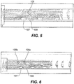
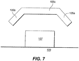
- a first deflector 105a can be positioned over an upstream end of the electronic component 107 and a second deflector 105b can be positioned over a downstream end of the electronic component 107.
- the first deflector 105a can include a negative angle of incidence relative to a flow in the flow channel 103 and the second deflector 105b can include a positive angle of incidence relative to a flow in the flow channel.
- the first deflector 105a and the second deflector 105b can be connected via a connector member 105c (e.g., and form a single piece as shown) such that the first deflector 105a, the second deflector 105b, and the connector member 105c overlay the electronic component 107.
- the connector member 105c can be parallel relative to a direction of the flow in the flow channel 103. While the first deflector 105a, the second deflector 105b, and the connector member 105c are shown as a single piece, it is contemplated that these components can be formed of any suitable number of pieces.
- Deflectors as described above were analyzed and tested via both computational fluid dynamics and experimental testing to determine the effect of various deflector positions and characteristics.
- the deflector 105 was placed at middle and downstream of an electronic component 107 (e.g., a third row of electronic components 107 in the direction of flow).
- the test results showed about 9% to about 22% loss in heat transfer coefficient (HTC) at about 0.35 cubic feet per minute (CFM) or a flow speed of about 0.12 m/s of airflow and about 4% to about 11% improvement of HTC at about 1.63 CFM or a flow speed of about 0.56 m/s.
- HTC heat transfer coefficient
- CFM cubic feet per minute
- the deflector 105 was repositioned to an upstream edge of the electronic component 107, which was shown to increase the velocity of air closer to the electronic component.
- This configuration provided about 0% to about 7% loss of HTC at 0.35 CFM and about 2% to about 12% improvement of HTC at about 1.63 CFM.
- a double deflector configuration was tested (having first deflector 105a and second deflector 105b).
- the electronic components 107 closest to the deflector e.g., the third row as shown
- the first and second deflectors 105a, 105b were plate shaped and were positioned about 2 mm upstream and about 2 mm downstream of the electronic component 107 (in a third row as shown).
- a second row of electronic components also saw improvement, while a first row of chips were seemingly unaffected.
- one or more deflectors can be added to a printed circuit assembly, for example, to direct the air flow and/or to increase the air velocity near a target component to improve the convective air cooling of the target component and/or adjacent components.
- Embodiments as described above can have positive cooling effect on the hot spots, for example.
- Embodiments as disclosed can improve convective cooling on a circuit board. It is contemplated that one having ordinary skill in the art, in view of this disclosure, can modify the deflector shape and/or placement in the flow channel for maximum cooling effectiveness.
- a method for thermal management of a circuit board includes modifying an air flow over the circuit board to increase speed or direction the air flow over a component of the circuit board using a deflector.
Landscapes
- Engineering & Computer Science (AREA)
- Microelectronics & Electronic Packaging (AREA)
- Physics & Mathematics (AREA)
- Thermal Sciences (AREA)
- Cooling Or The Like Of Electrical Apparatus (AREA)
- Cooling Or The Like Of Semiconductors Or Solid State Devices (AREA)
Applications Claiming Priority (1)
| Application Number | Priority Date | Filing Date | Title |
|---|---|---|---|
| US15/091,693 US9839156B2 (en) | 2016-04-06 | 2016-04-06 | Circuit board assemblies |
Publications (3)
| Publication Number | Publication Date |
|---|---|
| EP3229574A2 true EP3229574A2 (de) | 2017-10-11 |
| EP3229574A3 EP3229574A3 (de) | 2017-10-18 |
| EP3229574B1 EP3229574B1 (de) | 2021-06-02 |
Family
ID=58536781
Family Applications (1)
| Application Number | Title | Priority Date | Filing Date |
|---|---|---|---|
| EP17165363.7A Active EP3229574B1 (de) | 2016-04-06 | 2017-04-06 | Leiterplattenanordnungen |
Country Status (2)
| Country | Link |
|---|---|
| US (1) | US9839156B2 (de) |
| EP (1) | EP3229574B1 (de) |
Families Citing this family (1)
| Publication number | Priority date | Publication date | Assignee | Title |
|---|---|---|---|---|
| DE102023202837A1 (de) * | 2023-03-28 | 2024-10-02 | Siemens Aktiengesellschaft | Elektronikanordnung |
Family Cites Families (36)
| Publication number | Priority date | Publication date | Assignee | Title |
|---|---|---|---|---|
| US4750088A (en) | 1987-06-02 | 1988-06-07 | Hybricon Corporation | Card cage |
| US5734552A (en) | 1996-06-21 | 1998-03-31 | Sun Microsystems, Inc. | Airfoil deflector for cooling components |
| US6459576B1 (en) * | 1996-09-30 | 2002-10-01 | Intel Corporation | Fan based heat exchanger |
| US5914857A (en) | 1998-03-30 | 1999-06-22 | International Business Machines Corporation | Air flow devices for electronic boards |
| GB2369249B (en) * | 2000-11-06 | 2004-06-09 | 3Com Corp | Cooling apparatus including a flow guide |
| US6661666B1 (en) | 2002-09-24 | 2003-12-09 | Agilent Technologies, Inc. | Device for enhancing the local cooling of electronic packages subject to laminar air flow |
| US6989988B2 (en) * | 2003-02-21 | 2006-01-24 | Hewlett-Packard Development Company, L.P. | Duct for cooling multiple components in a processor-based device |
| US6912131B2 (en) * | 2003-08-27 | 2005-06-28 | Lucent Technologies Inc. | Electronic components card air deflector |
| US7167363B1 (en) * | 2003-09-08 | 2007-01-23 | Cisco Technology, Inc. | Methods and apparatus for directing an air stream through a circuit board assembly |
| US6955215B2 (en) | 2004-03-09 | 2005-10-18 | King Fahd University Of Petroleum And Minerals | Hybrid cooling system and method for cooling electronic devices |
| US7345873B2 (en) * | 2004-09-29 | 2008-03-18 | General Electric Company | System and method for cooling electronic systems |
| US7355850B2 (en) * | 2006-03-31 | 2008-04-08 | National Instruments Corporation | Vented and ducted sub-rack support member |
| EP1871155A1 (de) * | 2006-06-21 | 2007-12-26 | Alcatel Lucent | Baugruppenträger für Leiterplatten mit Kühlungsvorrichtung |
| US7554804B2 (en) * | 2006-06-30 | 2009-06-30 | Siemens Energy & Automation, Inc. | Electronic module configured for air flow therethrough and system including same |
| CN100499983C (zh) * | 2006-09-08 | 2009-06-10 | 富准精密工业(深圳)有限公司 | 散热装置 |
| US7450381B2 (en) * | 2006-12-04 | 2008-11-11 | International Business Machines Corporation | Thermal management apparatus and method for printed circuit boards |
| US7813121B2 (en) * | 2007-01-31 | 2010-10-12 | Liquid Computing Corporation | Cooling high performance computer systems |
| US7760506B1 (en) | 2007-06-06 | 2010-07-20 | Hewlett-Packard Development Company, L.P. | Electronic components, systems and apparatus with air flow devices |
| US7539015B2 (en) | 2007-07-31 | 2009-05-26 | Apple Inc. | Riser card housing |
| US8842431B2 (en) * | 2007-10-15 | 2014-09-23 | Alcatel Lucent | Horizontal chassis having front to back airflow |
| EP2101351B1 (de) * | 2008-03-13 | 2016-08-17 | Siemens Aktiengesellschaft | Kühlvorrichtung zur Kühlung eines Bauteils |
| TWI405074B (zh) * | 2009-01-08 | 2013-08-11 | 華碩電腦股份有限公司 | 散熱模組以及具有此散熱模組之電子裝置 |
| US8305759B2 (en) * | 2009-03-09 | 2012-11-06 | Hardcore Computer, Inc. | Gravity assisted directed liquid cooling |
| US8009417B2 (en) * | 2009-08-28 | 2011-08-30 | Hewlett-Packard Development Company, L.P. | Removable airflow guide assembly for a computer system |
| WO2011059644A1 (en) * | 2009-11-11 | 2011-05-19 | Nextronex Energy Systems, Llc | Inverter system |
| TW201202651A (en) * | 2010-07-07 | 2012-01-16 | Hon Hai Prec Ind Co Ltd | Air duct for cooling a plurality of electronic components and electronic device using the same |
| TWI397936B (zh) * | 2010-12-31 | 2013-06-01 | Giga Byte Tech Co Ltd | 鍵盤模組 |
| TW201309179A (zh) * | 2011-08-04 | 2013-02-16 | Wistron Corp | 流阻調節裝置及刀鋒伺服器 |
| US8634193B2 (en) * | 2011-12-05 | 2014-01-21 | Rockwell Automation Technologies, Inc. | Device and method using induction to improve natural convection cooling |
| WO2013130919A2 (en) | 2012-02-29 | 2013-09-06 | Inertech Ip Llc | Air flow distribution system for data center server racks |
| CN103425209A (zh) | 2012-05-14 | 2013-12-04 | 鸿富锦精密工业(深圳)有限公司 | 散热模组 |
| US8773852B2 (en) * | 2012-06-21 | 2014-07-08 | Breakingpoint Systems, Inc. | Air flow management device for use in an electronics system |
| US8885341B2 (en) * | 2012-08-28 | 2014-11-11 | Motorola Mobility Llc | Compact front to back horizontal cooling for rack mounted chassis |
| US9335802B2 (en) * | 2013-02-01 | 2016-05-10 | Dell Products, L.P. | System for cooling hard disk drives using vapor momentum driven by boiling of dielectric liquid |
| JP6794350B2 (ja) | 2014-07-02 | 2020-12-02 | ライフ テクノロジーズ コーポレーション | 半導体センサの表面処理 |
| US9241427B1 (en) | 2014-07-30 | 2016-01-19 | Seagate Technology Llc | Airfoil to provide directed cooling |
-
2016
- 2016-04-06 US US15/091,693 patent/US9839156B2/en active Active
-
2017
- 2017-04-06 EP EP17165363.7A patent/EP3229574B1/de active Active
Non-Patent Citations (1)
| Title |
|---|
| None |
Also Published As
| Publication number | Publication date |
|---|---|
| EP3229574B1 (de) | 2021-06-02 |
| US20170295669A1 (en) | 2017-10-12 |
| EP3229574A3 (de) | 2017-10-18 |
| US9839156B2 (en) | 2017-12-05 |
Similar Documents
| Publication | Publication Date | Title |
|---|---|---|
| US7167363B1 (en) | Methods and apparatus for directing an air stream through a circuit board assembly | |
| Gupta et al. | Numerical investigation towards implementation of punched winglet as vortex generator for performance improvement of a fin-and-tube heat exchanger | |
| CN101257780B (zh) | 电子设备导风装置 | |
| CN101641005B (zh) | 散热装置 | |
| US20140290925A1 (en) | Flow diverters to enhance heat sink performance | |
| US7311498B2 (en) | Microcircuit cooling for blades | |
| ATE308870T1 (de) | Mit führungen zur gleichmässigen führung von luftströmen versehene kühlvorrichtung für eine elektronische anlage | |
| EP2830401A1 (de) | Wärmetauscherplatte, wärmetauscher und gehäuse für eine kommunikationsbasisstation | |
| EP2717311B1 (de) | Effizienter Kühlkanal | |
| US9671178B2 (en) | Heat exchanger thermal fatigue stress reduction | |
| CN103025121A (zh) | 电子装置 | |
| CN102083296A (zh) | 散热装置 | |
| EP3071005B1 (de) | Baugruppenträger und endgerät | |
| CN104105382A (zh) | 散热片和包括该散热片的电力转换装置 | |
| TWM567396U (zh) | 導風罩及使用其的伺服器 | |
| EP3229574B1 (de) | Leiterplattenanordnungen | |
| JP2021034459A (ja) | 放熱部品及び実装基板 | |
| JPS61187501A (ja) | 流体冷却構造 | |
| CN114396662A (zh) | 电控盒和具有其的空调室外机 | |
| CN111479449B (zh) | 一种电子设备风冷机箱的冷却介质分配装置 | |
| JP2015008225A (ja) | 電子機器 | |
| Prajapati et al. | Thermal visualization and performance evaluation of the open matrix structures using liquid crystal thermography | |
| CN206695666U (zh) | 换热片、换热器及应用换热器的设备 | |
| Saha et al. | Heat transfer and pressure drop in a converging lattice structure for airfoil trailing edge cooling | |
| US20130194751A1 (en) | Controlling heat transfer using airflow-induced flutter of cantilevered elastic plates |
Legal Events
| Date | Code | Title | Description |
|---|---|---|---|
| PUAI | Public reference made under article 153(3) epc to a published international application that has entered the european phase |
Free format text: ORIGINAL CODE: 0009012 |
|
| STAA | Information on the status of an ep patent application or granted ep patent |
Free format text: STATUS: THE APPLICATION HAS BEEN PUBLISHED |
|
| PUAL | Search report despatched |
Free format text: ORIGINAL CODE: 0009013 |
|
| AK | Designated contracting states |
Kind code of ref document: A2 Designated state(s): AL AT BE BG CH CY CZ DE DK EE ES FI FR GB GR HR HU IE IS IT LI LT LU LV MC MK MT NL NO PL PT RO RS SE SI SK SM TR |
|
| AX | Request for extension of the european patent |
Extension state: BA ME |
|
| AK | Designated contracting states |
Kind code of ref document: A3 Designated state(s): AL AT BE BG CH CY CZ DE DK EE ES FI FR GB GR HR HU IE IS IT LI LT LU LV MC MK MT NL NO PL PT RO RS SE SI SK SM TR |
|
| AX | Request for extension of the european patent |
Extension state: BA ME |
|
| RIC1 | Information provided on ipc code assigned before grant |
Ipc: H05K 7/20 20060101AFI20170908BHEP |
|
| STAA | Information on the status of an ep patent application or granted ep patent |
Free format text: STATUS: REQUEST FOR EXAMINATION WAS MADE |
|
| 17P | Request for examination filed |
Effective date: 20180417 |
|
| RBV | Designated contracting states (corrected) |
Designated state(s): AL AT BE BG CH CY CZ DE DK EE ES FI FR GB GR HR HU IE IS IT LI LT LU LV MC MK MT NL NO PL PT RO RS SE SI SK SM TR |
|
| GRAP | Despatch of communication of intention to grant a patent |
Free format text: ORIGINAL CODE: EPIDOSNIGR1 |
|
| STAA | Information on the status of an ep patent application or granted ep patent |
Free format text: STATUS: GRANT OF PATENT IS INTENDED |
|
| INTG | Intention to grant announced |
Effective date: 20201119 |
|
| GRAS | Grant fee paid |
Free format text: ORIGINAL CODE: EPIDOSNIGR3 |
|
| GRAA | (expected) grant |
Free format text: ORIGINAL CODE: 0009210 |
|
| STAA | Information on the status of an ep patent application or granted ep patent |
Free format text: STATUS: THE PATENT HAS BEEN GRANTED |
|
| REG | Reference to a national code |
Ref country code: CH Ref legal event code: EP |
|
| AK | Designated contracting states |
Kind code of ref document: B1 Designated state(s): AL AT BE BG CH CY CZ DE DK EE ES FI FR GB GR HR HU IE IS IT LI LT LU LV MC MK MT NL NO PL PT RO RS SE SI SK SM TR |
|
| REG | Reference to a national code |
Ref country code: GB Ref legal event code: FG4D |
|
| REG | Reference to a national code |
Ref country code: AT Ref legal event code: REF Ref document number: 1399702 Country of ref document: AT Kind code of ref document: T Effective date: 20210615 |
|
| REG | Reference to a national code |
Ref country code: IE Ref legal event code: FG4D |
|
| REG | Reference to a national code |
Ref country code: DE Ref legal event code: R096 Ref document number: 602017039543 Country of ref document: DE |
|
| REG | Reference to a national code |
Ref country code: LT Ref legal event code: MG9D |
|
| PG25 | Lapsed in a contracting state [announced via postgrant information from national office to epo] |
Ref country code: LT Free format text: LAPSE BECAUSE OF FAILURE TO SUBMIT A TRANSLATION OF THE DESCRIPTION OR TO PAY THE FEE WITHIN THE PRESCRIBED TIME-LIMIT Effective date: 20210602 Ref country code: FI Free format text: LAPSE BECAUSE OF FAILURE TO SUBMIT A TRANSLATION OF THE DESCRIPTION OR TO PAY THE FEE WITHIN THE PRESCRIBED TIME-LIMIT Effective date: 20210602 Ref country code: BG Free format text: LAPSE BECAUSE OF FAILURE TO SUBMIT A TRANSLATION OF THE DESCRIPTION OR TO PAY THE FEE WITHIN THE PRESCRIBED TIME-LIMIT Effective date: 20210902 Ref country code: HR Free format text: LAPSE BECAUSE OF FAILURE TO SUBMIT A TRANSLATION OF THE DESCRIPTION OR TO PAY THE FEE WITHIN THE PRESCRIBED TIME-LIMIT Effective date: 20210602 |
|
| REG | Reference to a national code |
Ref country code: NL Ref legal event code: MP Effective date: 20210602 |
|
| REG | Reference to a national code |
Ref country code: AT Ref legal event code: MK05 Ref document number: 1399702 Country of ref document: AT Kind code of ref document: T Effective date: 20210602 |
|
| PG25 | Lapsed in a contracting state [announced via postgrant information from national office to epo] |
Ref country code: PL Free format text: LAPSE BECAUSE OF FAILURE TO SUBMIT A TRANSLATION OF THE DESCRIPTION OR TO PAY THE FEE WITHIN THE PRESCRIBED TIME-LIMIT Effective date: 20210602 Ref country code: NO Free format text: LAPSE BECAUSE OF FAILURE TO SUBMIT A TRANSLATION OF THE DESCRIPTION OR TO PAY THE FEE WITHIN THE PRESCRIBED TIME-LIMIT Effective date: 20210902 Ref country code: RS Free format text: LAPSE BECAUSE OF FAILURE TO SUBMIT A TRANSLATION OF THE DESCRIPTION OR TO PAY THE FEE WITHIN THE PRESCRIBED TIME-LIMIT Effective date: 20210602 Ref country code: SE Free format text: LAPSE BECAUSE OF FAILURE TO SUBMIT A TRANSLATION OF THE DESCRIPTION OR TO PAY THE FEE WITHIN THE PRESCRIBED TIME-LIMIT Effective date: 20210602 Ref country code: LV Free format text: LAPSE BECAUSE OF FAILURE TO SUBMIT A TRANSLATION OF THE DESCRIPTION OR TO PAY THE FEE WITHIN THE PRESCRIBED TIME-LIMIT Effective date: 20210602 Ref country code: GR Free format text: LAPSE BECAUSE OF FAILURE TO SUBMIT A TRANSLATION OF THE DESCRIPTION OR TO PAY THE FEE WITHIN THE PRESCRIBED TIME-LIMIT Effective date: 20210903 |
|
| PG25 | Lapsed in a contracting state [announced via postgrant information from national office to epo] |
Ref country code: SK Free format text: LAPSE BECAUSE OF FAILURE TO SUBMIT A TRANSLATION OF THE DESCRIPTION OR TO PAY THE FEE WITHIN THE PRESCRIBED TIME-LIMIT Effective date: 20210602 Ref country code: SM Free format text: LAPSE BECAUSE OF FAILURE TO SUBMIT A TRANSLATION OF THE DESCRIPTION OR TO PAY THE FEE WITHIN THE PRESCRIBED TIME-LIMIT Effective date: 20210602 Ref country code: AT Free format text: LAPSE BECAUSE OF FAILURE TO SUBMIT A TRANSLATION OF THE DESCRIPTION OR TO PAY THE FEE WITHIN THE PRESCRIBED TIME-LIMIT Effective date: 20210602 Ref country code: EE Free format text: LAPSE BECAUSE OF FAILURE TO SUBMIT A TRANSLATION OF THE DESCRIPTION OR TO PAY THE FEE WITHIN THE PRESCRIBED TIME-LIMIT Effective date: 20210602 Ref country code: CZ Free format text: LAPSE BECAUSE OF FAILURE TO SUBMIT A TRANSLATION OF THE DESCRIPTION OR TO PAY THE FEE WITHIN THE PRESCRIBED TIME-LIMIT Effective date: 20210602 Ref country code: NL Free format text: LAPSE BECAUSE OF FAILURE TO SUBMIT A TRANSLATION OF THE DESCRIPTION OR TO PAY THE FEE WITHIN THE PRESCRIBED TIME-LIMIT Effective date: 20210602 Ref country code: PT Free format text: LAPSE BECAUSE OF FAILURE TO SUBMIT A TRANSLATION OF THE DESCRIPTION OR TO PAY THE FEE WITHIN THE PRESCRIBED TIME-LIMIT Effective date: 20211004 Ref country code: RO Free format text: LAPSE BECAUSE OF FAILURE TO SUBMIT A TRANSLATION OF THE DESCRIPTION OR TO PAY THE FEE WITHIN THE PRESCRIBED TIME-LIMIT Effective date: 20210602 Ref country code: ES Free format text: LAPSE BECAUSE OF FAILURE TO SUBMIT A TRANSLATION OF THE DESCRIPTION OR TO PAY THE FEE WITHIN THE PRESCRIBED TIME-LIMIT Effective date: 20210602 |
|
| REG | Reference to a national code |
Ref country code: DE Ref legal event code: R097 Ref document number: 602017039543 Country of ref document: DE |
|
| PLBE | No opposition filed within time limit |
Free format text: ORIGINAL CODE: 0009261 |
|
| STAA | Information on the status of an ep patent application or granted ep patent |
Free format text: STATUS: NO OPPOSITION FILED WITHIN TIME LIMIT |
|
| PG25 | Lapsed in a contracting state [announced via postgrant information from national office to epo] |
Ref country code: DK Free format text: LAPSE BECAUSE OF FAILURE TO SUBMIT A TRANSLATION OF THE DESCRIPTION OR TO PAY THE FEE WITHIN THE PRESCRIBED TIME-LIMIT Effective date: 20210602 |
|
| 26N | No opposition filed |
Effective date: 20220303 |
|
| PG25 | Lapsed in a contracting state [announced via postgrant information from national office to epo] |
Ref country code: AL Free format text: LAPSE BECAUSE OF FAILURE TO SUBMIT A TRANSLATION OF THE DESCRIPTION OR TO PAY THE FEE WITHIN THE PRESCRIBED TIME-LIMIT Effective date: 20210602 |
|
| PG25 | Lapsed in a contracting state [announced via postgrant information from national office to epo] |
Ref country code: IT Free format text: LAPSE BECAUSE OF FAILURE TO SUBMIT A TRANSLATION OF THE DESCRIPTION OR TO PAY THE FEE WITHIN THE PRESCRIBED TIME-LIMIT Effective date: 20210602 |
|
| REG | Reference to a national code |
Ref country code: CH Ref legal event code: PL |
|
| REG | Reference to a national code |
Ref country code: BE Ref legal event code: MM Effective date: 20220430 |
|
| PG25 | Lapsed in a contracting state [announced via postgrant information from national office to epo] |
Ref country code: MC Free format text: LAPSE BECAUSE OF FAILURE TO SUBMIT A TRANSLATION OF THE DESCRIPTION OR TO PAY THE FEE WITHIN THE PRESCRIBED TIME-LIMIT Effective date: 20210602 Ref country code: LU Free format text: LAPSE BECAUSE OF NON-PAYMENT OF DUE FEES Effective date: 20220406 Ref country code: LI Free format text: LAPSE BECAUSE OF NON-PAYMENT OF DUE FEES Effective date: 20220430 Ref country code: CH Free format text: LAPSE BECAUSE OF NON-PAYMENT OF DUE FEES Effective date: 20220430 |
|
| PG25 | Lapsed in a contracting state [announced via postgrant information from national office to epo] |
Ref country code: BE Free format text: LAPSE BECAUSE OF NON-PAYMENT OF DUE FEES Effective date: 20220430 |
|
| PG25 | Lapsed in a contracting state [announced via postgrant information from national office to epo] |
Ref country code: IE Free format text: LAPSE BECAUSE OF NON-PAYMENT OF DUE FEES Effective date: 20220406 |
|
| P01 | Opt-out of the competence of the unified patent court (upc) registered |
Effective date: 20230522 |
|
| PG25 | Lapsed in a contracting state [announced via postgrant information from national office to epo] |
Ref country code: HU Free format text: LAPSE BECAUSE OF FAILURE TO SUBMIT A TRANSLATION OF THE DESCRIPTION OR TO PAY THE FEE WITHIN THE PRESCRIBED TIME-LIMIT; INVALID AB INITIO Effective date: 20170406 |
|
| PG25 | Lapsed in a contracting state [announced via postgrant information from national office to epo] |
Ref country code: MK Free format text: LAPSE BECAUSE OF FAILURE TO SUBMIT A TRANSLATION OF THE DESCRIPTION OR TO PAY THE FEE WITHIN THE PRESCRIBED TIME-LIMIT Effective date: 20210602 Ref country code: CY Free format text: LAPSE BECAUSE OF FAILURE TO SUBMIT A TRANSLATION OF THE DESCRIPTION OR TO PAY THE FEE WITHIN THE PRESCRIBED TIME-LIMIT Effective date: 20210602 |
|
| PG25 | Lapsed in a contracting state [announced via postgrant information from national office to epo] |
Ref country code: MT Free format text: LAPSE BECAUSE OF FAILURE TO SUBMIT A TRANSLATION OF THE DESCRIPTION OR TO PAY THE FEE WITHIN THE PRESCRIBED TIME-LIMIT Effective date: 20210602 |
|
| PGFP | Annual fee paid to national office [announced via postgrant information from national office to epo] |
Ref country code: DE Payment date: 20250319 Year of fee payment: 9 |
|
| PG25 | Lapsed in a contracting state [announced via postgrant information from national office to epo] |
Ref country code: TR Free format text: LAPSE BECAUSE OF FAILURE TO SUBMIT A TRANSLATION OF THE DESCRIPTION OR TO PAY THE FEE WITHIN THE PRESCRIBED TIME-LIMIT Effective date: 20210602 |
|
| PGFP | Annual fee paid to national office [announced via postgrant information from national office to epo] |
Ref country code: GB Payment date: 20260319 Year of fee payment: 10 |
|
| PGFP | Annual fee paid to national office [announced via postgrant information from national office to epo] |
Ref country code: FR Payment date: 20260320 Year of fee payment: 10 |