EP3229307A2 - Energy source enclosure systems and methods with through-air thermal management - Google Patents
Energy source enclosure systems and methods with through-air thermal management Download PDFInfo
- Publication number
- EP3229307A2 EP3229307A2 EP17164789.4A EP17164789A EP3229307A2 EP 3229307 A2 EP3229307 A2 EP 3229307A2 EP 17164789 A EP17164789 A EP 17164789A EP 3229307 A2 EP3229307 A2 EP 3229307A2
- Authority
- EP
- European Patent Office
- Prior art keywords
- enclosure
- energy source
- air
- inlet
- outlet
- Prior art date
- Legal status (The legal status is an assumption and is not a legal conclusion. Google has not performed a legal analysis and makes no representation as to the accuracy of the status listed.)
- Granted
Links
Images



Classifications
-
- H—ELECTRICITY
- H01—ELECTRIC ELEMENTS
- H01M—PROCESSES OR MEANS, e.g. BATTERIES, FOR THE DIRECT CONVERSION OF CHEMICAL ENERGY INTO ELECTRICAL ENERGY
- H01M50/00—Constructional details or processes of manufacture of the non-active parts of electrochemical cells other than fuel cells, e.g. hybrid cells
- H01M50/20—Mountings; Secondary casings or frames; Racks, modules or packs; Suspension devices; Shock absorbers; Transport or carrying devices; Holders
-
- B—PERFORMING OPERATIONS; TRANSPORTING
- B60—VEHICLES IN GENERAL
- B60K—ARRANGEMENT OR MOUNTING OF PROPULSION UNITS OR OF TRANSMISSIONS IN VEHICLES; ARRANGEMENT OR MOUNTING OF PLURAL DIVERSE PRIME-MOVERS IN VEHICLES; AUXILIARY DRIVES FOR VEHICLES; INSTRUMENTATION OR DASHBOARDS FOR VEHICLES; ARRANGEMENTS IN CONNECTION WITH COOLING, AIR INTAKE, GAS EXHAUST OR FUEL SUPPLY OF PROPULSION UNITS IN VEHICLES
- B60K1/00—Arrangement or mounting of electrical propulsion units
- B60K1/04—Arrangement or mounting of electrical propulsion units of the electric storage means for propulsion
-
- B—PERFORMING OPERATIONS; TRANSPORTING
- B60—VEHICLES IN GENERAL
- B60L—PROPULSION OF ELECTRICALLY-PROPELLED VEHICLES; SUPPLYING ELECTRIC POWER FOR AUXILIARY EQUIPMENT OF ELECTRICALLY-PROPELLED VEHICLES; ELECTRODYNAMIC BRAKE SYSTEMS FOR VEHICLES IN GENERAL; MAGNETIC SUSPENSION OR LEVITATION FOR VEHICLES; MONITORING OPERATING VARIABLES OF ELECTRICALLY-PROPELLED VEHICLES; ELECTRIC SAFETY DEVICES FOR ELECTRICALLY-PROPELLED VEHICLES
- B60L50/00—Electric propulsion with power supplied within the vehicle
- B60L50/50—Electric propulsion with power supplied within the vehicle using propulsion power supplied by batteries or fuel cells
- B60L50/60—Electric propulsion with power supplied within the vehicle using propulsion power supplied by batteries or fuel cells using power supplied by batteries
- B60L50/64—Constructional details of batteries specially adapted for electric vehicles
-
- B—PERFORMING OPERATIONS; TRANSPORTING
- B60—VEHICLES IN GENERAL
- B60L—PROPULSION OF ELECTRICALLY-PROPELLED VEHICLES; SUPPLYING ELECTRIC POWER FOR AUXILIARY EQUIPMENT OF ELECTRICALLY-PROPELLED VEHICLES; ELECTRODYNAMIC BRAKE SYSTEMS FOR VEHICLES IN GENERAL; MAGNETIC SUSPENSION OR LEVITATION FOR VEHICLES; MONITORING OPERATING VARIABLES OF ELECTRICALLY-PROPELLED VEHICLES; ELECTRIC SAFETY DEVICES FOR ELECTRICALLY-PROPELLED VEHICLES
- B60L50/00—Electric propulsion with power supplied within the vehicle
- B60L50/50—Electric propulsion with power supplied within the vehicle using propulsion power supplied by batteries or fuel cells
- B60L50/60—Electric propulsion with power supplied within the vehicle using propulsion power supplied by batteries or fuel cells using power supplied by batteries
- B60L50/66—Arrangements of batteries
-
- B—PERFORMING OPERATIONS; TRANSPORTING
- B60—VEHICLES IN GENERAL
- B60L—PROPULSION OF ELECTRICALLY-PROPELLED VEHICLES; SUPPLYING ELECTRIC POWER FOR AUXILIARY EQUIPMENT OF ELECTRICALLY-PROPELLED VEHICLES; ELECTRODYNAMIC BRAKE SYSTEMS FOR VEHICLES IN GENERAL; MAGNETIC SUSPENSION OR LEVITATION FOR VEHICLES; MONITORING OPERATING VARIABLES OF ELECTRICALLY-PROPELLED VEHICLES; ELECTRIC SAFETY DEVICES FOR ELECTRICALLY-PROPELLED VEHICLES
- B60L58/00—Methods or circuit arrangements for monitoring or controlling batteries or fuel cells, specially adapted for electric vehicles
- B60L58/10—Methods or circuit arrangements for monitoring or controlling batteries or fuel cells, specially adapted for electric vehicles for monitoring or controlling batteries
- B60L58/24—Methods or circuit arrangements for monitoring or controlling batteries or fuel cells, specially adapted for electric vehicles for monitoring or controlling batteries for controlling the temperature of batteries
- B60L58/26—Methods or circuit arrangements for monitoring or controlling batteries or fuel cells, specially adapted for electric vehicles for monitoring or controlling batteries for controlling the temperature of batteries by cooling
-
- B—PERFORMING OPERATIONS; TRANSPORTING
- B66—HOISTING; LIFTING; HAULING
- B66F—HOISTING, LIFTING, HAULING OR PUSHING, NOT OTHERWISE PROVIDED FOR, e.g. DEVICES WHICH APPLY A LIFTING OR PUSHING FORCE DIRECTLY TO THE SURFACE OF A LOAD
- B66F9/00—Devices for lifting or lowering bulky or heavy goods for loading or unloading purposes
- B66F9/06—Devices for lifting or lowering bulky or heavy goods for loading or unloading purposes movable, with their loads, on wheels or the like, e.g. fork-lift trucks
- B66F9/075—Constructional features or details
- B66F9/07595—Cooling arrangements for device or operator
-
- H—ELECTRICITY
- H01—ELECTRIC ELEMENTS
- H01M—PROCESSES OR MEANS, e.g. BATTERIES, FOR THE DIRECT CONVERSION OF CHEMICAL ENERGY INTO ELECTRICAL ENERGY
- H01M10/00—Secondary cells; Manufacture thereof
- H01M10/42—Methods or arrangements for servicing or maintenance of secondary cells or secondary half-cells
-
- H—ELECTRICITY
- H01—ELECTRIC ELEMENTS
- H01M—PROCESSES OR MEANS, e.g. BATTERIES, FOR THE DIRECT CONVERSION OF CHEMICAL ENERGY INTO ELECTRICAL ENERGY
- H01M10/00—Secondary cells; Manufacture thereof
- H01M10/60—Heating or cooling; Temperature control
- H01M10/61—Types of temperature control
- H01M10/613—Cooling or keeping cold
-
- H—ELECTRICITY
- H01—ELECTRIC ELEMENTS
- H01M—PROCESSES OR MEANS, e.g. BATTERIES, FOR THE DIRECT CONVERSION OF CHEMICAL ENERGY INTO ELECTRICAL ENERGY
- H01M10/00—Secondary cells; Manufacture thereof
- H01M10/60—Heating or cooling; Temperature control
- H01M10/61—Types of temperature control
- H01M10/617—Types of temperature control for achieving uniformity or desired distribution of temperature
-
- H—ELECTRICITY
- H01—ELECTRIC ELEMENTS
- H01M—PROCESSES OR MEANS, e.g. BATTERIES, FOR THE DIRECT CONVERSION OF CHEMICAL ENERGY INTO ELECTRICAL ENERGY
- H01M10/00—Secondary cells; Manufacture thereof
- H01M10/60—Heating or cooling; Temperature control
- H01M10/62—Heating or cooling; Temperature control specially adapted for specific applications
- H01M10/625—Vehicles
-
- H—ELECTRICITY
- H01—ELECTRIC ELEMENTS
- H01M—PROCESSES OR MEANS, e.g. BATTERIES, FOR THE DIRECT CONVERSION OF CHEMICAL ENERGY INTO ELECTRICAL ENERGY
- H01M10/00—Secondary cells; Manufacture thereof
- H01M10/60—Heating or cooling; Temperature control
- H01M10/65—Means for temperature control structurally associated with the cells
- H01M10/655—Solid structures for heat exchange or heat conduction
- H01M10/6556—Solid parts with flow channel passages or pipes for heat exchange
-
- H—ELECTRICITY
- H01—ELECTRIC ELEMENTS
- H01M—PROCESSES OR MEANS, e.g. BATTERIES, FOR THE DIRECT CONVERSION OF CHEMICAL ENERGY INTO ELECTRICAL ENERGY
- H01M10/00—Secondary cells; Manufacture thereof
- H01M10/60—Heating or cooling; Temperature control
- H01M10/65—Means for temperature control structurally associated with the cells
- H01M10/656—Means for temperature control structurally associated with the cells characterised by the type of heat-exchange fluid
- H01M10/6561—Gases
-
- H—ELECTRICITY
- H01—ELECTRIC ELEMENTS
- H01M—PROCESSES OR MEANS, e.g. BATTERIES, FOR THE DIRECT CONVERSION OF CHEMICAL ENERGY INTO ELECTRICAL ENERGY
- H01M10/00—Secondary cells; Manufacture thereof
- H01M10/60—Heating or cooling; Temperature control
- H01M10/65—Means for temperature control structurally associated with the cells
- H01M10/656—Means for temperature control structurally associated with the cells characterised by the type of heat-exchange fluid
- H01M10/6561—Gases
- H01M10/6563—Gases with forced flow, e.g. by blowers
-
- H—ELECTRICITY
- H05—ELECTRIC TECHNIQUES NOT OTHERWISE PROVIDED FOR
- H05K—PRINTED CIRCUITS; CASINGS OR CONSTRUCTIONAL DETAILS OF ELECTRIC APPARATUS; MANUFACTURE OF ASSEMBLAGES OF ELECTRICAL COMPONENTS
- H05K7/00—Constructional details common to different types of electric apparatus
- H05K7/20—Modifications to facilitate cooling, ventilating, or heating
- H05K7/20845—Modifications to facilitate cooling, ventilating, or heating for automotive electronic casings
- H05K7/20863—Forced ventilation, e.g. on heat dissipaters coupled to components
-
- H—ELECTRICITY
- H05—ELECTRIC TECHNIQUES NOT OTHERWISE PROVIDED FOR
- H05K—PRINTED CIRCUITS; CASINGS OR CONSTRUCTIONAL DETAILS OF ELECTRIC APPARATUS; MANUFACTURE OF ASSEMBLAGES OF ELECTRICAL COMPONENTS
- H05K7/00—Constructional details common to different types of electric apparatus
- H05K7/20—Modifications to facilitate cooling, ventilating, or heating
- H05K7/2089—Modifications to facilitate cooling, ventilating, or heating for power electronics, e.g. for inverters for controlling motor
- H05K7/20909—Forced ventilation, e.g. on heat dissipaters coupled to components
-
- B—PERFORMING OPERATIONS; TRANSPORTING
- B60—VEHICLES IN GENERAL
- B60K—ARRANGEMENT OR MOUNTING OF PROPULSION UNITS OR OF TRANSMISSIONS IN VEHICLES; ARRANGEMENT OR MOUNTING OF PLURAL DIVERSE PRIME-MOVERS IN VEHICLES; AUXILIARY DRIVES FOR VEHICLES; INSTRUMENTATION OR DASHBOARDS FOR VEHICLES; ARRANGEMENTS IN CONNECTION WITH COOLING, AIR INTAKE, GAS EXHAUST OR FUEL SUPPLY OF PROPULSION UNITS IN VEHICLES
- B60K1/00—Arrangement or mounting of electrical propulsion units
- B60K2001/003—Arrangement or mounting of electrical propulsion units with means for cooling the electrical propulsion units
- B60K2001/005—Arrangement or mounting of electrical propulsion units with means for cooling the electrical propulsion units the electric storage means
-
- B—PERFORMING OPERATIONS; TRANSPORTING
- B60—VEHICLES IN GENERAL
- B60K—ARRANGEMENT OR MOUNTING OF PROPULSION UNITS OR OF TRANSMISSIONS IN VEHICLES; ARRANGEMENT OR MOUNTING OF PLURAL DIVERSE PRIME-MOVERS IN VEHICLES; AUXILIARY DRIVES FOR VEHICLES; INSTRUMENTATION OR DASHBOARDS FOR VEHICLES; ARRANGEMENTS IN CONNECTION WITH COOLING, AIR INTAKE, GAS EXHAUST OR FUEL SUPPLY OF PROPULSION UNITS IN VEHICLES
- B60K1/00—Arrangement or mounting of electrical propulsion units
- B60K1/04—Arrangement or mounting of electrical propulsion units of the electric storage means for propulsion
- B60K2001/0405—Arrangement or mounting of electrical propulsion units of the electric storage means for propulsion characterised by their position
-
- B—PERFORMING OPERATIONS; TRANSPORTING
- B60—VEHICLES IN GENERAL
- B60L—PROPULSION OF ELECTRICALLY-PROPELLED VEHICLES; SUPPLYING ELECTRIC POWER FOR AUXILIARY EQUIPMENT OF ELECTRICALLY-PROPELLED VEHICLES; ELECTRODYNAMIC BRAKE SYSTEMS FOR VEHICLES IN GENERAL; MAGNETIC SUSPENSION OR LEVITATION FOR VEHICLES; MONITORING OPERATING VARIABLES OF ELECTRICALLY-PROPELLED VEHICLES; ELECTRIC SAFETY DEVICES FOR ELECTRICALLY-PROPELLED VEHICLES
- B60L2200/00—Type of vehicles
- B60L2200/40—Working vehicles
-
- B—PERFORMING OPERATIONS; TRANSPORTING
- B60—VEHICLES IN GENERAL
- B60L—PROPULSION OF ELECTRICALLY-PROPELLED VEHICLES; SUPPLYING ELECTRIC POWER FOR AUXILIARY EQUIPMENT OF ELECTRICALLY-PROPELLED VEHICLES; ELECTRODYNAMIC BRAKE SYSTEMS FOR VEHICLES IN GENERAL; MAGNETIC SUSPENSION OR LEVITATION FOR VEHICLES; MONITORING OPERATING VARIABLES OF ELECTRICALLY-PROPELLED VEHICLES; ELECTRIC SAFETY DEVICES FOR ELECTRICALLY-PROPELLED VEHICLES
- B60L2200/00—Type of vehicles
- B60L2200/40—Working vehicles
- B60L2200/42—Fork lift trucks
-
- B—PERFORMING OPERATIONS; TRANSPORTING
- B60—VEHICLES IN GENERAL
- B60L—PROPULSION OF ELECTRICALLY-PROPELLED VEHICLES; SUPPLYING ELECTRIC POWER FOR AUXILIARY EQUIPMENT OF ELECTRICALLY-PROPELLED VEHICLES; ELECTRODYNAMIC BRAKE SYSTEMS FOR VEHICLES IN GENERAL; MAGNETIC SUSPENSION OR LEVITATION FOR VEHICLES; MONITORING OPERATING VARIABLES OF ELECTRICALLY-PROPELLED VEHICLES; ELECTRIC SAFETY DEVICES FOR ELECTRICALLY-PROPELLED VEHICLES
- B60L2240/00—Control parameters of input or output; Target parameters
- B60L2240/40—Drive Train control parameters
- B60L2240/54—Drive Train control parameters related to batteries
- B60L2240/545—Temperature
-
- B—PERFORMING OPERATIONS; TRANSPORTING
- B60—VEHICLES IN GENERAL
- B60W—CONJOINT CONTROL OF VEHICLE SUB-UNITS OF DIFFERENT TYPE OR DIFFERENT FUNCTION; CONTROL SYSTEMS SPECIALLY ADAPTED FOR HYBRID VEHICLES; ROAD VEHICLE DRIVE CONTROL SYSTEMS FOR PURPOSES NOT RELATED TO THE CONTROL OF A PARTICULAR SUB-UNIT
- B60W2300/00—Indexing codes relating to the type of vehicle
- B60W2300/12—Trucks; Load vehicles
- B60W2300/121—Fork lift trucks, Clarks
-
- Y—GENERAL TAGGING OF NEW TECHNOLOGICAL DEVELOPMENTS; GENERAL TAGGING OF CROSS-SECTIONAL TECHNOLOGIES SPANNING OVER SEVERAL SECTIONS OF THE IPC; TECHNICAL SUBJECTS COVERED BY FORMER USPC CROSS-REFERENCE ART COLLECTIONS [XRACs] AND DIGESTS
- Y02—TECHNOLOGIES OR APPLICATIONS FOR MITIGATION OR ADAPTATION AGAINST CLIMATE CHANGE
- Y02E—REDUCTION OF GREENHOUSE GAS [GHG] EMISSIONS, RELATED TO ENERGY GENERATION, TRANSMISSION OR DISTRIBUTION
- Y02E60/00—Enabling technologies; Technologies with a potential or indirect contribution to GHG emissions mitigation
- Y02E60/10—Energy storage using batteries
-
- Y—GENERAL TAGGING OF NEW TECHNOLOGICAL DEVELOPMENTS; GENERAL TAGGING OF CROSS-SECTIONAL TECHNOLOGIES SPANNING OVER SEVERAL SECTIONS OF THE IPC; TECHNICAL SUBJECTS COVERED BY FORMER USPC CROSS-REFERENCE ART COLLECTIONS [XRACs] AND DIGESTS
- Y02—TECHNOLOGIES OR APPLICATIONS FOR MITIGATION OR ADAPTATION AGAINST CLIMATE CHANGE
- Y02P—CLIMATE CHANGE MITIGATION TECHNOLOGIES IN THE PRODUCTION OR PROCESSING OF GOODS
- Y02P90/00—Enabling technologies with a potential contribution to greenhouse gas [GHG] emissions mitigation
- Y02P90/60—Electric or hybrid propulsion means for production processes
-
- Y—GENERAL TAGGING OF NEW TECHNOLOGICAL DEVELOPMENTS; GENERAL TAGGING OF CROSS-SECTIONAL TECHNOLOGIES SPANNING OVER SEVERAL SECTIONS OF THE IPC; TECHNICAL SUBJECTS COVERED BY FORMER USPC CROSS-REFERENCE ART COLLECTIONS [XRACs] AND DIGESTS
- Y02—TECHNOLOGIES OR APPLICATIONS FOR MITIGATION OR ADAPTATION AGAINST CLIMATE CHANGE
- Y02T—CLIMATE CHANGE MITIGATION TECHNOLOGIES RELATED TO TRANSPORTATION
- Y02T10/00—Road transport of goods or passengers
- Y02T10/60—Other road transportation technologies with climate change mitigation effect
- Y02T10/70—Energy storage systems for electromobility, e.g. batteries
-
- Y—GENERAL TAGGING OF NEW TECHNOLOGICAL DEVELOPMENTS; GENERAL TAGGING OF CROSS-SECTIONAL TECHNOLOGIES SPANNING OVER SEVERAL SECTIONS OF THE IPC; TECHNICAL SUBJECTS COVERED BY FORMER USPC CROSS-REFERENCE ART COLLECTIONS [XRACs] AND DIGESTS
- Y02—TECHNOLOGIES OR APPLICATIONS FOR MITIGATION OR ADAPTATION AGAINST CLIMATE CHANGE
- Y02T—CLIMATE CHANGE MITIGATION TECHNOLOGIES RELATED TO TRANSPORTATION
- Y02T90/00—Enabling technologies or technologies with a potential or indirect contribution to GHG emissions mitigation
- Y02T90/10—Technologies relating to charging of electric vehicles
- Y02T90/16—Information or communication technologies improving the operation of electric vehicles
Definitions
- the present invention relates to systems and methods of enclosing one or more energy source cells while providing through air thermal management for the energy source cells and other components.
- Material handling vehicles are commonly found in warehouses, factories, shipping yards, and, generally, wherever pallets, large packages, or loads of goods are required to be transported from place to place. Material handling vehicles typically include load bearing forks for lifting packages or pallets for transporting, a drive motor for propelling the truck, a steering control mechanism, and a brake.
- a common energy source for electrically based material handling equipment is a lead acid battery (LAB).
- LAB lead acid battery
- improvements in alternative energy source technology have led to other energy sources being used, such as lithium ion batteries (LIBs) and fuel cells.
- LIBs lithium ion batteries
- the present invention provides for systems and methods for enclosing components of a battery while allowing for through air cooling.
- a system for enclosing an energy source includes an enclosure having a front wall, a rear wall, a top wall, a bottom wall, side walls and forming an interior compartment.
- the system further includes an inlet channel integrally formed with the front wall and in fluid communication with the interior compartment, the inlet channel defined by an inlet louver and an inlet flange, the inlet flange defined by two or more inlet segments, and an outlet channel integrally formed with the rear wall and in fluid communication with the interior compartment, the outlet channel defined by an outlet louver and an outlet flange, the outlet flange defined by two or more outlet segments.
- the system also includes one or more energy source cells positioned within the interior compartment and a cooling fan in fluid communication with the inlet channel and the interior compartment.
- the cooling fan operates to draw air through the inlet channel to the interior compartment such that air within the interior compartment is expelled out of the outlet channel.
- the system includes a charger positioned within the enclosure being electrically coupled with the one or more energy source cells.
- the system includes a battery management system positioned within the enclosure being electrically coupled with the one or more energy source cells.
- the one or more energy source cells are positioned below the battery management system and the charger within the enclosure.
- the system includes an electrical cord coupled with the charger.
- the system includes a recessed compartment formed within a top wall of the enclosure and the electrical cord is retractable into the compartment.
- the system includes a wall aperture formed within a side wall of the enclosure that allows water that pools within the compartment to flow out of the compartment.
- the system includes one or more drainage holes formed within a bottom wall of the enclosure.
- the one or more energy source cells include a first energy source cell and a second energy source cell.
- the first energy source cell is a lithium ion battery cell and the second energy source cell is a lithium ion battery cell.
- a system for enclosing an energy source for a material handling vehicle includes an enclosure having a first wall, a second wall, and an interior compartment.
- the system also includes an inlet channel integrally formed with the front wall and in fluid communication with the interior compartment and an outlet channel integrally formed with the rear wall and in fluid communication with the interior compartment.
- the system also includes one or more energy source cells positioned within the interior compartment, a charger positioned within the enclosure being electrically coupled with the one or more energy source cells, and a battery management system positioned within the enclosure being electrically coupled with the one or more energy source cells.
- the system also includes a cooling fan in fluid communication with the inlet channel and the interior compartment such that the cooling fan operates to draw air through the inlet channel to the interior compartment such that air within the interior compartment is expelled out of the outlet channel.
- all mechanical aspects of the enclosure have at least an IP3X Ingress Protection rating.
- the system includes an air inlet louver positioned adjacent the inlet channel and an air outlet louver positioned adjacent the air outlet channel.
- the cooling fan is positioned in an upper corner of the enclosure and the one or more energy source cells are positioned in one or more lower corners of the enclosure.
- a method of enclosing an energy source of a material handling vehicle and providing cooling thereto includes drawing air through an air inlet channel of an enclosure defined by at least a front wall and a rear wall via a cooling fan, propelling the air into an interior compartment of the enclosure such that the air flows past one or more energy source cells, a charger, and a battery management system, expelling air out of an outlet channel that is integrally formed with the rear wall and in fluid communication with the interior compartment.
- the air inlet channel is defined by an inlet louver and an inlet flanged defined by two or more inlet segments
- the outlet channel is defined by an outlet louver and an outlet flange defined by two or more outlet segments.
- the method includes draining moisture out of the interior compartment through one or more drainage holes positioned within a bottom wall of the enclosure. In some embodiments, the method includes retracting a power cord that emanates from a compartment within a recessed compartment formed within a top wall of the enclosure when the charger is not in use. In still some embodiments, the method includes draining water out of the compartment through a wall aperture formed along a side wall of the enclosure.
- the present invention provides a system for enclosing an energy source, the system comprising: an enclosure having a front wall, a rear wall, a top wall, a bottom wall, side walls and forming an interior compartment; an inlet channel integrally formed with the front wall and in fluid communication with the interior compartment, the inlet channel defined by an inlet louver and an inlet flange, the inlet flange defined by two or more inlet segments; an outlet channel integrally formed with the rear wall and in fluid communication with the interior compartment, the outlet channel defined by an outlet louver and an outlet flange, the outlet flange defined by two or more outlet segments; one or more energy source cells positioned within the interior compartment; a cooling fan in fluid communication with the inlet channel and the interior compartment; and wherein the cooling fan operates to draw air through the inlet channel to the interior compartment such that air within the interior compartment is expelled out of the outlet channel.
- the system further comprises a charger positioned within the enclosure and is electrically coupled with the one or more energy source cells.
- the system further comprises a battery management system positioned within the enclosure and electrically coupled with the one or more energy source cells.
- the system can include the one or more energy source cells that are positioned below the battery management system and the charger within the enclosure.
- the system further comprises an electrical cord coupled with the charger.
- system further comprises a recessed compartment formed within a top wall of the enclosure that is configured to include the electrical cord that is retractable into the compartment.
- system further comprises a wall aperture formed within a side wall of the enclosure that allows water that pools within the compartment to flow out of the compartment.
- the system further comprises one or more drainage holes formed within the bottom wall of the enclosure.
- the system can include the one or more energy source cells that include a first energy source cell and a second energy source cell.
- the system can include the first energy source cell that is a lithium ion battery cell and the second energy source cell that is a lithium ion battery cell.
- the present invention provides a system for enclosing an energy source for a material handling vehicle, the system comprising: an enclosure having a first wall, a second wall different than the first wall, and an interior compartment; an inlet channel integrally formed with the first wall and in fluid communication with the interior compartment, the inlet channel defined by an inlet louver and an inlet flange, the inlet flange defined by two or more inlet segments; an outlet channel integrally formed with the second wall and in fluid communication with the interior compartment, the outlet channel is defined by an outlet louver and an outlet flange, the outlet flange defined by two or more outlet segments; one or more energy source cells positioned within the interior compartment; a charger positioned within the enclosure being electrically coupled with the one or more energy source cells; a battery management system positioned within the enclosure being electrically coupled with the one or more energy source cells; and a cooling fan in fluid communication with the inlet channel and the interior compartment; wherein the cooling fan is configured to draw air through the inlet channel to the interior compartment such that
- the system can include the one or more energy source cells that comprise lithium ion cells.
- the system further comprises one or more drainage holes within a bottom wall of the enclosure.
- the system can include the enclosure that satisfies at least an IP3X Ingress Protection rating.
- the system can include the cooling fan that is secured to at least one of the two or more inlet segments to allow air to pass through the at least one of the two or more inlet segments.
- the system can include the cooling fan that is positioned in an upper corner of the enclosure and the one or more energy source cells that are positioned in one or more lower corners of the enclosure.
- a method of cooling an energy source comprises: drawing air through an air inlet channel of an enclosure defined by at least a first wall and a second wall via a cooling fan; propelling the air, via the cooling fan, into an interior compartment of the enclosure such that the air flows past at least one of an energy source cell, a charger, and a battery management system; and expelling the air out of an outlet channel that is integrally formed with the second wall and in fluid communication with the interior compartment, wherein the air inlet channel is defined by an inlet louver and an inlet flange defined by two or more inlet segments, and wherein the air outlet channel is defined by an outlet louver and an outlet flange defined by two or more outlet segments.
- the method further comprises: draining moisture out of the interior compartment through one or more drainage holes positioned within a bottom wall of the enclosure.
- the method further comprises: retracting a power cord that extends from a compartment within a recessed compartment formed within a top wall of the enclosure.
- the method further comprises: draining water out of the compartment through a wall aperture formed along a side wall of the enclosure.
- material handling vehicles are designed in a variety of configurations to perform a variety of tasks. Although the material handling vehicle described herein is shown in the figure as a reach truck, it will be apparent to those of skill in the art that the present invention is not limited to vehicles of this type or purpose, and can also be provided in various other types of material handling vehicle configurations, including, for example, pallet trucks, order pickers, narrow-aisle turret trucks, and any other material handling vehicle.
- the energy source cells that provide energy for the material handling vehicles that are positioned within the enclosure described herein may be comprised of one or more of the following, but are not limited to: a lead acid battery; a flow battery such as a vanadium redox battery, a zinc-bromine battery, or a zinc-cerium battery; a lithium air battery; a lithium-ion battery such as a beltway battery, a lithium ion manganese oxide battery, a lithium ion polymer battery, a lithium iron phosphate battery, a lithium-sulfur battery, or a lithium-titanate battery; a molten salt battery; a nickel-cadmium battery; a nickel hydrogen battery; a nickel-iron battery; a nickel metal hydride battery; an organic radical battery; a polymer-based battery; a polysulfide bromide
- Improvements in battery technology have allowed the battery cells that provide energy to material handling vehicles to be miniaturized such that the battery cells provide the same amount of energy without requiring the space that previous batteries required.
- other components such as a battery management system, a charger, or other battery components, can be included within the enclosure that surrounds the energy source.
- the material handling vehicle 20 includes a body 22, a fork carriage 24 with at least one load bearing fork 26, a motor compartment (not shown) housing a motor (not shown), an energy source compartment 28 for housing an energy source 30.
- the energy source 30 is comprised of at least one battery pack 32.
- the energy source 30 may be comprised of a plurality of battery packs 32.
- the battery pack 32 is shown positioned within a counter weight 34.
- the material handling vehicle 20 may further include an operator compartment 38.
- the energy source 30 and the counter weight 34 are collectively referred to as a battery 40.
- the material handling vehicle 20 is shown with the fork carriage 24 in an uppermost position.
- the battery pack 32 is surrounded by a battery enclosure 42.
- the battery enclosure 42 is defined by a front wall 44, a left wall 46, a rear wall 48, a right wall 50, a top wall 52, and a bottom wall 124 (see Fig. 6 ).
- an electrical cord 54 can extend from a compartment 56 within the top wall 52.
- the electrical cord 54 may be retractable or non-retractable.
- a cable gland can be used to seal the electrical cord 54 passing through the top wall 52. Cable glands may also be used for power and communication cables passing through the top wall 52, or any other wall.
- the compartment 56 can have a slanted bottom surface that allows water that may build up within the compartment 56, e.g ., during washing of the battery pack 32, to flow out of a wall aperture 58.
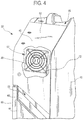
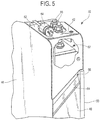
- the battery enclosure 42 also includes an inlet louver 60 that defines an air inlet 62 and further includes an outlet louver 64 that defines an air outlet 66.
- Both the inlet louver 60 and the outlet louver 64 can be angled slats or flat strips that allow air to pass through the front and rear walls of the enclosure.
- the louvers 60, 64 may have other forms known to those of ordinary skill in the art.
- the configuration of the inlet louver 60 and the outlet louver 64 can prevent water at a pressure from entering the interior of the battery enclosure 42 and allows air to enter the air inlet 62 and the air outlet 66, as will be described in greater detail hereinafter below.
- the air inlet 62 and/or the air outlet 66 may be formed in any shape known to those skilled in the art.
- the air inlet 62 and/or the air outlet 66 may be in the shape of a triangle, a square, a rectangle, a circle, an oval, a hexagon, or any other polygonal shape known to those of ordinary skill in the art.
- the air inlet 62 and/or the air outlet 66 have a width dimension of between about 0.5cm to about 5cm, or between about 1cm to about 4cm, or about 1.5cm or more or less.
- the air inlet 62 and/or the air outlet 66 have a length dimension of between about 5cm and about 15cm, or between about 8cm and about 12cm, or about 10.5cm or more or less.
- FIG. 6 a cross section of the battery pack 32 is shown taken through line 6-6 of FIG. 3 .
- a first battery cell 68 and a second battery cell 70 which are both connected to the battery enclosure 42 with a plurality of connectors 72. More or less battery cells are contemplated.
- the connectors 72 may be screws, rivets, pins, or any other connector known to those of ordinary skill in the art.
- a battery management system 74 and a charger 76 can have disposed thereon a plurality of fins 78.
- a single battery cell may be used.
- the battery cell may be positioned where the second battery cell 70 is positioned within the enclosure 42.
- the fins 78 can direct air flow received from a cooling fan 80 across one or more surfaces of the charger and downward toward the first battery cell 68 and the second battery cell 70.
- the fins 78 may have an angular configuration that is approximately 45 degrees from a plane that is perpendicular to the top wall 52.
- the fins 78 may also have an angular configuration of between zero degrees and about 90 degrees.
- the fins 78 can act as cooling fins and can help to cool the charger 76.
- the plug 54 for the charger 76 can be plugged into a 120V outlet. In other embodiments, the charger 76 can be plugged into a 240V outlet, or into an outlet having other voltages known in the art. Further included within the enclosure 42 can be the cooling fan 80.
- the cooling fan 80 can be energized based on a sensed temperature with the enclosure 42. In other embodiments, the cooling fan 80 may not be included inside the enclosure and air flow may be achieved by convection or by some other means. The cooling fan 80 may also be located along or within a different portion of the enclosure 42. In some embodiments, the fan may be included along one or more of the walls 44, 46, 48, 50, and 52.
- an inlet flange 82 and an outlet flange 84 are shown, which can help direct the flow of air through the battery enclosure 42 to cool one or more components of the battery pack 32.
- the inlet flange 82 can comprise one or more inlet segments.
- the front wall 44 can be coincident with an angled inlet segment 90 of the inlet flange 82, which can protrude upward and inward toward the compartment 56 and can intersect a vertical inlet segment 92.
- the vertical segment 92 can extend upward toward the top wall 52 where it can intersect with a fan inlet segment 94.
- the fan segment 94 can also be angled upward and inward, although not required, and can terminate spaced apart from the top wall 52 of the enclosure 42 creating a gap 96.
- the gap 96 may allow for air to flow there through.
- the gap 96 is positioned to prevent water from entering an interior of the casing 45.
- An outer side 98 of the vertical segment 92 and an inner side 100 of the front wall 44 of the enclosure 42 form an inlet channel 102 through which air is drawn into the enclosure 42 when the cooling fan 80 is turned on or when air is drawn through by some other means.
- the cooling fan 80 can be secured to the fan inlet segment 94 with one or more connectors 72 or by some other connection means, to allow air to pass through the fan and through the fan inlet segment 94.
- the cooling fan 80 can be secured to the fan inlet segment 94 by a snap fit, an interference fit, adhesion, or any other method of coupling known to those skilled in the art.
- there is no gap 96 rather, the fan inlet segment 94 terminates into the top wall 52 of the battery pack 32.
- any of the inlet segments 90, 92, 94 of the inlet flange 82 can be either formed with, or connected to, both the right wall 46 and the left wall 50 of the battery pack 32.
- the inlet segments 90, 92, 94 can be secured in an airtight fashion such that any air that is drawn through the air inlet 62, along the inlet segments 90, 92, 94 and into the cooling fan 80, does not escape into the battery pack 32 without being drawn through at least one of the cooling fan 80 or the gap 96.
- the inlet segments 90, 92, 94 are not airtight, and air can escape through the sides thereof.
- the inlet segments 90, 92, 94 can be a unitary element, or individual elements.
- the outlet flange 84 can also comprise one or more outlet segments.
- An angled outlet segment 110 can be coincident with the rear wall 48 and can extend inward and upward toward the compartment 56.
- a vertical outlet segment 112 can extend from an end of the angled segment 110 upward toward the top wall 52.
- the vertical segment 112 can terminate spaced apart from the top wall 52 to form a gap 114.
- the outlet segments 110, 112 of the outlet flange 84 can be connected to both the right wall 46 and the left wall 50 of the enclosure 42 in an airtight fashion. In some embodiments, the outlet segments 110, 112 can be connected to the walls 46, 40 in a non-airtight fashion.
- An outer side 116 of the vertical segment 112 and an inner side 118 of the rear wall 48 can form an outlet channel 120 through which air is expelled from the enclosure 42 when the cooling fan 80 is turned on.
- the outlet flange 84 may include one or more additional segments that can provide for additional or different air flow pathways.
- the outlet segments 110, 112 may comprise a unitary element, or may comprise separable elements.
- one or more drainage holes 122 can be provided along a bottom wall 124 of the battery enclosure 42.
- the drainage holes 122 can allow moisture to escape from the battery pack 32.
- the drainage holes 122 can be provided in one location along the bottom wall of the battery enclosure 42.
- the drainage holes can be provided at two or more locations along the bottom wall of the battery enclosure 42. As illustrated in FIG. 6 , the drainage holes can be provided in two locations. The first location can be generally below the first battery cell 68 and the second location can be generally below the second battery cell 70.
- the one or more drainage holes 122 may be formed in any shape known to those of ordinary skill in the art, such as, but not limited to, the shape of a triangle, a square, a circle, a rectangle, or any other polygonal shape.
- the one or more drainage holes 122 may have at least one dimension, i.e ., a length, a width, a diameter, or any other dimension, of between about 0.1cm and about 8cm, or between about 1cm and about 6cm, or between about 2cm and about 5cm or more or less.
- the drainage holes 122 can be rectangular and can have dimensions of about 2.5cm by about 5cm.
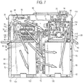
- FIG. 7 a schematic of the air flow through the battery enclosure 42 is shown.
- air entering through the air inlet 62 is directed through the inlet channel 102 upward along the segments 90, 92, 94 of the inlet flange 82.
- the air can then be drawn through the cooling fan 80 and can be projected into the interior of the enclosure 42.
- the air can be first directed over the charger 76, which may produce thermal output within the enclosure during certain time periods, such as when the battery pack 32 is being charged. While the air is directed over the charger 76, the air can flow laterally through the fins 78 of the charger 76.
- the fins 78 of the charger 76 may be formed in any configuration that provides for air flow over the charger 76.
- the layout of components within the enclosure can be based on the thermal output of the components. In order to reduce convection heating, components that produce a higher thermal output can be placed lower or lowest in the enclosure 42.
- some of the air that is drawn through the cooling fan 80 can flow toward the battery management system 74, which can provide cooling thereto.
- Other air can flow along the sides of the first battery cell 68 and/or along the sides of the second battery cell 70.
- the battery enclosure 42 is not hermetically sealed, therefore air can escape through any gap along any of the walls 44, 46, 48, 50, 52, 124 of the enclosure 42.
- the battery enclosure 42 can be hermetically sealed or partially hermetically sealed to allow for air to escape through certain portions, but not other portions of the enclosure 42.
- the air that has cooled or otherwise passed over one or more components of the battery pack 32 within the battery enclosure 42 can be directed out of the enclosure 42 through the air outlet 66 via the outlet channel 120. After the air flows into the outlet channel 120, the air can flow downward along the outlet flange 84 and can flow into the surrounding atmosphere through the air outlet 66. While the air flow schematic illustrated in FIG. 7 illustrates air moving from an upper left portion of the enclosure downward along the components of the battery pack 32 and out of the enclosure 42 through the air outlet 66 in the upper right hand corner, other air flow configurations are possible.
- the air outlet 66 may be positioned at a different point along one or more of the right wall 46, the left wall 50, the top wall 52, or at a different point along the rear wall 48.
- the air inlet 62 may be positioned at a different point along one or more of the right wall 46, the left wall 50, the top wall 52, or at a different point along the front wall 44.
- More than one air inlet 62 and/or one air outlet 66 may be included within the enclosure 42.
- the enclosure 42 may include two or more air inlets 62 and/or two or more air outlets 66.
- the configuration of the segments 90, 92, 94 of the inlet flange 82, and of the segments 110, 112 of the outlet flange 84 can prevent water at a certain pressure or within a range of pressures from entering the enclosure 42 during cleaning or spraying of the battery pack 32. As a result, the enclosure 42 can be wash-down proof.
- the segments 90, 92, 94, 110, 112 may be positioned in other configurations.
- more segments may be included to further minimize the amount of water that can reach the interior of the enclosure 42.
- one or more baffles may be provided adjacent one or more of the segments 90, 92, 94, 110, 112 that may direct air flow.
- the advantages of the design of the battery enclosure 42 as described herein include allowing the flow of air within the enclosure 42 to cool the system via an indirect flow path.
- the temperature rating of some or all components can be in excess of 140 degrees Celsius.
- IP Ingress Protection
- the battery pack 32 as described herein can satisfy at least the IP3X requirements.
- the battery pack 32 can satisfy the IP4X requirement.
- the battery pack 32 can satisfy the IPX6 test criteria.
- the battery pack 32 can satisfy up to or more than the IPX9 test criteria.
- the enclosure 42 and other components within the enclosure 42 may be made of any material known to those skilled in the art.
- the enclosure 42 is made of one or more of a wide variety of well-known polymeric materials, including, for example, polyethylene (PE), low density polyethylene (LDPE), high density polyethylene (HDPE), polyethylene terephthalate (PET), crystalline PET, amorphous PET, polyethylene glycol terephthalate, polystyrene (PS), polyamide (PA), polyvinyl chloride (PVC), polycarbonate (PC), poly(styrene:acrylonitrile) (SAN), polymethylmethacrylate (PMMA), polypropylene (PP), polyethylene naphthalene (PEN), polyethylene furanoate (PEF), PET homopolymers, PEN copolymers, PET/PEN resin blends, PEN homopolymers, over molded thermoplastic elastomers (TPE), fluropolymers, polysulphones, polyimides, cellulose acetate,
Landscapes
- Engineering & Computer Science (AREA)
- Chemical & Material Sciences (AREA)
- Chemical Kinetics & Catalysis (AREA)
- Electrochemistry (AREA)
- General Chemical & Material Sciences (AREA)
- Manufacturing & Machinery (AREA)
- Transportation (AREA)
- Mechanical Engineering (AREA)
- Life Sciences & Earth Sciences (AREA)
- Sustainable Development (AREA)
- Sustainable Energy (AREA)
- Power Engineering (AREA)
- Microelectronics & Electronic Packaging (AREA)
- Thermal Sciences (AREA)
- Physics & Mathematics (AREA)
- Structural Engineering (AREA)
- Combustion & Propulsion (AREA)
- Civil Engineering (AREA)
- Geology (AREA)
- Secondary Cells (AREA)
- Battery Mounting, Suspending (AREA)
- Cooling, Air Intake And Gas Exhaust, And Fuel Tank Arrangements In Propulsion Units (AREA)
Abstract
Description
- This application claims priority to
U.S. Provisional Application No. 62/317,812 filed on April 04, 2016 - Not applicable.
- The present invention relates to systems and methods of enclosing one or more energy source cells while providing through air thermal management for the energy source cells and other components.
- Material handling vehicles are commonly found in warehouses, factories, shipping yards, and, generally, wherever pallets, large packages, or loads of goods are required to be transported from place to place. Material handling vehicles typically include load bearing forks for lifting packages or pallets for transporting, a drive motor for propelling the truck, a steering control mechanism, and a brake.
- A common energy source for electrically based material handling equipment is a lead acid battery (LAB). However, improvements in alternative energy source technology have led to other energy sources being used, such as lithium ion batteries (LIBs) and fuel cells.
- Importantly, existing battery enclosure systems do not provide for the cooling necessary for some components while allowing the enclosure to be subjected to a water wash-down. Therefore, it is desirable to provide a battery enclosure system that adequately provides for thermal cooling for components within the enclosure while allowing a water wash-down.
- The present invention provides for systems and methods for enclosing components of a battery while allowing for through air cooling.
- In one form, a system for enclosing an energy source includes an enclosure having a front wall, a rear wall, a top wall, a bottom wall, side walls and forming an interior compartment. The system further includes an inlet channel integrally formed with the front wall and in fluid communication with the interior compartment, the inlet channel defined by an inlet louver and an inlet flange, the inlet flange defined by two or more inlet segments, and an outlet channel integrally formed with the rear wall and in fluid communication with the interior compartment, the outlet channel defined by an outlet louver and an outlet flange, the outlet flange defined by two or more outlet segments. The system also includes one or more energy source cells positioned within the interior compartment and a cooling fan in fluid communication with the inlet channel and the interior compartment. The cooling fan operates to draw air through the inlet channel to the interior compartment such that air within the interior compartment is expelled out of the outlet channel. In another embodiment, the system includes a charger positioned within the enclosure being electrically coupled with the one or more energy source cells. In still a further form, the system includes a battery management system positioned within the enclosure being electrically coupled with the one or more energy source cells.
- In some embodiments, the one or more energy source cells are positioned below the battery management system and the charger within the enclosure. In another form, the system includes an electrical cord coupled with the charger. In another form, the system includes a recessed compartment formed within a top wall of the enclosure and the electrical cord is retractable into the compartment. In still another form the system includes a wall aperture formed within a side wall of the enclosure that allows water that pools within the compartment to flow out of the compartment.
- In yet another form, the system includes one or more drainage holes formed within a bottom wall of the enclosure. In some embodiments, the one or more energy source cells include a first energy source cell and a second energy source cell. In some embodiments, the first energy source cell is a lithium ion battery cell and the second energy source cell is a lithium ion battery cell.
- In some embodiments, a system for enclosing an energy source for a material handling vehicle includes an enclosure having a first wall, a second wall, and an interior compartment. The system also includes an inlet channel integrally formed with the front wall and in fluid communication with the interior compartment and an outlet channel integrally formed with the rear wall and in fluid communication with the interior compartment. The system also includes one or more energy source cells positioned within the interior compartment, a charger positioned within the enclosure being electrically coupled with the one or more energy source cells, and a battery management system positioned within the enclosure being electrically coupled with the one or more energy source cells. The system also includes a cooling fan in fluid communication with the inlet channel and the interior compartment such that the cooling fan operates to draw air through the inlet channel to the interior compartment such that air within the interior compartment is expelled out of the outlet channel.
- In some embodiments, all mechanical aspects of the enclosure have at least an IP3X Ingress Protection rating. In some embodiments, the system includes an air inlet louver positioned adjacent the inlet channel and an air outlet louver positioned adjacent the air outlet channel. In still some embodiments, the cooling fan is positioned in an upper corner of the enclosure and the one or more energy source cells are positioned in one or more lower corners of the enclosure.
- In another embodiment, a method of enclosing an energy source of a material handling vehicle and providing cooling thereto includes drawing air through an air inlet channel of an enclosure defined by at least a front wall and a rear wall via a cooling fan, propelling the air into an interior compartment of the enclosure such that the air flows past one or more energy source cells, a charger, and a battery management system, expelling air out of an outlet channel that is integrally formed with the rear wall and in fluid communication with the interior compartment. The air inlet channel is defined by an inlet louver and an inlet flanged defined by two or more inlet segments, and the outlet channel is defined by an outlet louver and an outlet flange defined by two or more outlet segments. In some embodiments, the method includes draining moisture out of the interior compartment through one or more drainage holes positioned within a bottom wall of the enclosure. In some embodiments, the method includes retracting a power cord that emanates from a compartment within a recessed compartment formed within a top wall of the enclosure when the charger is not in use. In still some embodiments, the method includes draining water out of the compartment through a wall aperture formed along a side wall of the enclosure.
- In some embodiments, the present invention provides a system for enclosing an energy source, the system comprising: an enclosure having a front wall, a rear wall, a top wall, a bottom wall, side walls and forming an interior compartment; an inlet channel integrally formed with the front wall and in fluid communication with the interior compartment, the inlet channel defined by an inlet louver and an inlet flange, the inlet flange defined by two or more inlet segments; an outlet channel integrally formed with the rear wall and in fluid communication with the interior compartment, the outlet channel defined by an outlet louver and an outlet flange, the outlet flange defined by two or more outlet segments; one or more energy source cells positioned within the interior compartment; a cooling fan in fluid communication with the inlet channel and the interior compartment; and wherein the cooling fan operates to draw air through the inlet channel to the interior compartment such that air within the interior compartment is expelled out of the outlet channel.
- In some embodiments, the system further comprises a charger positioned within the enclosure and is electrically coupled with the one or more energy source cells.
- In some embodiments, the system further comprises a battery management system positioned within the enclosure and electrically coupled with the one or more energy source cells.
- In some embodiments, the system can include the one or more energy source cells that are positioned below the battery management system and the charger within the enclosure.
- In some embodiments, the system further comprises an electrical cord coupled with the charger.
- In some embodiments, the system further comprises a recessed compartment formed within a top wall of the enclosure that is configured to include the electrical cord that is retractable into the compartment.
- In some embodiments, the system further comprises a wall aperture formed within a side wall of the enclosure that allows water that pools within the compartment to flow out of the compartment.
- In some embodiments, the system further comprises one or more drainage holes formed within the bottom wall of the enclosure.
- In some embodiments, the system can include the one or more energy source cells that include a first energy source cell and a second energy source cell.
- In some embodiments, the system can include the first energy source cell that is a lithium ion battery cell and the second energy source cell that is a lithium ion battery cell.
- In some embodiments, the present invention provides a system for enclosing an energy source for a material handling vehicle, the system comprising: an enclosure having a first wall, a second wall different than the first wall, and an interior compartment; an inlet channel integrally formed with the first wall and in fluid communication with the interior compartment, the inlet channel defined by an inlet louver and an inlet flange, the inlet flange defined by two or more inlet segments; an outlet channel integrally formed with the second wall and in fluid communication with the interior compartment, the outlet channel is defined by an outlet louver and an outlet flange, the outlet flange defined by two or more outlet segments; one or more energy source cells positioned within the interior compartment; a charger positioned within the enclosure being electrically coupled with the one or more energy source cells; a battery management system positioned within the enclosure being electrically coupled with the one or more energy source cells; and a cooling fan in fluid communication with the inlet channel and the interior compartment; wherein the cooling fan is configured to draw air through the inlet channel to the interior compartment such that air within the interior compartment is expelled out of the outlet channel.
- In some embodiments, the system can include the one or more energy source cells that comprise lithium ion cells.
- In some embodiments, the system further comprises one or more drainage holes within a bottom wall of the enclosure.
- In some embodiments, the system can include the enclosure that satisfies at least an IP3X Ingress Protection rating.
- In some embodiments, the system can include the cooling fan that is secured to at least one of the two or more inlet segments to allow air to pass through the at least one of the two or more inlet segments.
- In some embodiments, the system can include the cooling fan that is positioned in an upper corner of the enclosure and the one or more energy source cells that are positioned in one or more lower corners of the enclosure.
- In another embodiment, a method of cooling an energy source comprises: drawing air through an air inlet channel of an enclosure defined by at least a first wall and a second wall via a cooling fan; propelling the air, via the cooling fan, into an interior compartment of the enclosure such that the air flows past at least one of an energy source cell, a charger, and a battery management system; and expelling the air out of an outlet channel that is integrally formed with the second wall and in fluid communication with the interior compartment, wherein the air inlet channel is defined by an inlet louver and an inlet flange defined by two or more inlet segments, and wherein the air outlet channel is defined by an outlet louver and an outlet flange defined by two or more outlet segments.
- In some embodiments, the method further comprises: draining moisture out of the interior compartment through one or more drainage holes positioned within a bottom wall of the enclosure.
- In some embodiments, the method further comprises: retracting a power cord that extends from a compartment within a recessed compartment formed within a top wall of the enclosure.
- In some embodiments, the method further comprises: draining water out of the compartment through a wall aperture formed along a side wall of the enclosure.
- The foregoing features of the mentioned embodiments can be considered individually or in any combination of each other and will not be regarded as limiting the scope of protection of any of the features described or displayed in the application.
-
-
FIG. 1 is a perspective view of a material handling vehicle using a battery according to the present disclosure. -
FIG. 2 is a front, left isometric view of an enclosure surrounding a battery pack as disclosed herein. -
FIG. 3 is a rear, left isometric view of the enclosure ofFIG. 2 . -
FIG. 4 is a partial front, left isometric view of the enclosure ofFIG. 2 . -
FIG. 5 is a partial rear, left isometric view of the enclosure ofFIG. 2 . -
FIG. 6 illustrates a cross sectional view of the enclosure and battery pack as disclosed herein taken through line 6-6 ofFIG. 3 . -
FIG. 7 is a cross sectional schematic view illustrating the flow of air through the enclosure and battery pack ofFIG. 6 . - Before any embodiments of the invention are explained in detail, it is to be understood that the invention is not limited in its application to the details of construction and the arrangement of components set forth in the following description or illustrated in the following drawings. The invention is capable of other embodiments and of being practiced or of being carried out in various ways. Also, it is to be understood that the phraseology and terminology used herein is for the purpose of description and should not be regarded as limiting. The use of "including," "comprising," or "having" and variations thereof herein is meant to encompass the items listed thereafter and equivalents thereof as well as additional items. Unless specified or limited otherwise, the terms "mounted," "connected," "supported," and "coupled" and variations thereof are used broadly and encompass both direct and indirect mountings, connections, supports, and couplings. Further, "connected" and "coupled" are not restricted to physical or mechanical connections or couplings.
- The following discussion is presented to enable a person skilled in the art to make and use embodiments of the invention. Various modifications to the illustrated embodiments will be readily apparent to those skilled in the art, and the generic principles herein can be applied to other embodiments and applications without departing from embodiments of the invention. Thus, embodiments of the invention are not intended to be limited to embodiments shown, but are to be accorded the widest scope consistent with the principles and features disclosed herein. The following detailed description is to be read with reference to the figures, in which like elements in different figures have like reference numerals. The figures, which are not necessarily to scale, depict selected embodiments and are not intended to limit the scope of embodiments of the invention. Skilled artisans will recognize the examples provided herein have many useful alternatives and fall within the scope of embodiments of the invention.
- It is also to be appreciated that material handling vehicles are designed in a variety of configurations to perform a variety of tasks. Although the material handling vehicle described herein is shown in the figure as a reach truck, it will be apparent to those of skill in the art that the present invention is not limited to vehicles of this type or purpose, and can also be provided in various other types of material handling vehicle configurations, including, for example, pallet trucks, order pickers, narrow-aisle turret trucks, and any other material handling vehicle.
- Turning to the figures, the following description and drawing figures pertain to an embodiment of the invention directed toward an enclosure with through-air thermal management for a battery pack that powers a material handling vehicle. The energy source cells that provide energy for the material handling vehicles that are positioned within the enclosure described herein may be comprised of one or more of the following, but are not limited to: a lead acid battery; a flow battery such as a vanadium redox battery, a zinc-bromine battery, or a zinc-cerium battery; a lithium air battery; a lithium-ion battery such as a beltway battery, a lithium ion manganese oxide battery, a lithium ion polymer battery, a lithium iron phosphate battery, a lithium-sulfur battery, or a lithium-titanate battery; a molten salt battery; a nickel-cadmium battery; a nickel hydrogen battery; a nickel-iron battery; a nickel metal hydride battery; an organic radical battery; a polymer-based battery; a polysulfide bromide battery; a potassium-ion battery; a rechargeable alkaline battery; a rechargeable fuel battery; a silicon air battery; a silver-zinc battery; a silver calcium battery; a sodium-ion battery; a sodium-sulfur battery; a sugar battery; a super iron battery; or an UltraBattery.
- Improvements in battery technology have allowed the battery cells that provide energy to material handling vehicles to be miniaturized such that the battery cells provide the same amount of energy without requiring the space that previous batteries required. As a result, other components, such as a battery management system, a charger, or other battery components, can be included within the enclosure that surrounds the energy source.
- Referring to
FIG. 1 , amaterial handling vehicle 20 embodying an aspect of the invention is shown. Thematerial handling vehicle 20 includes abody 22, afork carriage 24 with at least oneload bearing fork 26, a motor compartment (not shown) housing a motor (not shown), anenergy source compartment 28 for housing anenergy source 30. Theenergy source 30 is comprised of at least onebattery pack 32. In some embodiments, theenergy source 30 may be comprised of a plurality of battery packs 32. As illustrated inFIG. 1 , thebattery pack 32 is shown positioned within acounter weight 34. Thematerial handling vehicle 20 may further include anoperator compartment 38. Theenergy source 30 and thecounter weight 34 are collectively referred to as a battery 40. Thematerial handling vehicle 20 is shown with thefork carriage 24 in an uppermost position. - As illustrated in
FIGS. 2 and3 , thebattery pack 32 is surrounded by abattery enclosure 42. In some embodiments and as shown in the FIGS., thebattery enclosure 42 is defined by afront wall 44, aleft wall 46, arear wall 48, aright wall 50, atop wall 52, and a bottom wall 124 (seeFig. 6 ). Further, anelectrical cord 54 can extend from acompartment 56 within thetop wall 52. Theelectrical cord 54 may be retractable or non-retractable. In some embodiments, a cable gland can be used to seal theelectrical cord 54 passing through thetop wall 52. Cable glands may also be used for power and communication cables passing through thetop wall 52, or any other wall. In some embodiments and as described in greater detail below, thecompartment 56 can have a slanted bottom surface that allows water that may build up within thecompartment 56, e.g., during washing of thebattery pack 32, to flow out of awall aperture 58. - Referring now to
FIGS. 4 and5 , thebattery enclosure 42 also includes aninlet louver 60 that defines anair inlet 62 and further includes anoutlet louver 64 that defines anair outlet 66. Both theinlet louver 60 and theoutlet louver 64 can be angled slats or flat strips that allow air to pass through the front and rear walls of the enclosure. In other embodiments, thelouvers inlet louver 60 and theoutlet louver 64 can prevent water at a pressure from entering the interior of thebattery enclosure 42 and allows air to enter theair inlet 62 and theair outlet 66, as will be described in greater detail hereinafter below. - The
air inlet 62 and/or theair outlet 66 may be formed in any shape known to those skilled in the art. For example, theair inlet 62 and/or theair outlet 66 may be in the shape of a triangle, a square, a rectangle, a circle, an oval, a hexagon, or any other polygonal shape known to those of ordinary skill in the art. In some embodiments, theair inlet 62 and/or theair outlet 66 have a width dimension of between about 0.5cm to about 5cm, or between about 1cm to about 4cm, or about 1.5cm or more or less. In some embodiments, theair inlet 62 and/or theair outlet 66 have a length dimension of between about 5cm and about 15cm, or between about 8cm and about 12cm, or about 10.5cm or more or less. - Referring now to
FIG. 6 , a cross section of thebattery pack 32 is shown taken through line 6-6 ofFIG. 3 . Within theenclosure 42 is afirst battery cell 68 and asecond battery cell 70, which are both connected to thebattery enclosure 42 with a plurality ofconnectors 72. More or less battery cells are contemplated. Theconnectors 72 may be screws, rivets, pins, or any other connector known to those of ordinary skill in the art. Further illustrated inFIG. 6 is abattery management system 74 and acharger 76. Thecharger 76 can have disposed thereon a plurality of fins 78. In some embodiments, a single battery cell may be used. In some embodiments where a single battery cell is used rather than two or more battery cells, the battery cell may be positioned where thesecond battery cell 70 is positioned within theenclosure 42. - The fins 78 can direct air flow received from a cooling
fan 80 across one or more surfaces of the charger and downward toward thefirst battery cell 68 and thesecond battery cell 70. The fins 78 may have an angular configuration that is approximately 45 degrees from a plane that is perpendicular to thetop wall 52. The fins 78 may also have an angular configuration of between zero degrees and about 90 degrees. The fins 78 can act as cooling fins and can help to cool thecharger 76. In some embodiments, theplug 54 for thecharger 76 can be plugged into a 120V outlet. In other embodiments, thecharger 76 can be plugged into a 240V outlet, or into an outlet having other voltages known in the art. Further included within theenclosure 42 can be the coolingfan 80. In some embodiments, the coolingfan 80 can be energized based on a sensed temperature with theenclosure 42. In other embodiments, the coolingfan 80 may not be included inside the enclosure and air flow may be achieved by convection or by some other means. The coolingfan 80 may also be located along or within a different portion of theenclosure 42. In some embodiments, the fan may be included along one or more of thewalls - As further illustrated in
FIG. 6 , aninlet flange 82 and anoutlet flange 84 are shown, which can help direct the flow of air through thebattery enclosure 42 to cool one or more components of thebattery pack 32. Theinlet flange 82 can comprise one or more inlet segments. Thefront wall 44 can be coincident with anangled inlet segment 90 of theinlet flange 82, which can protrude upward and inward toward thecompartment 56 and can intersect avertical inlet segment 92. Thevertical segment 92 can extend upward toward thetop wall 52 where it can intersect with afan inlet segment 94. Thefan segment 94 can also be angled upward and inward, although not required, and can terminate spaced apart from thetop wall 52 of theenclosure 42 creating agap 96. Thegap 96 may allow for air to flow there through. In some embodiments, thegap 96 is positioned to prevent water from entering an interior of the casing 45. Anouter side 98 of thevertical segment 92 and aninner side 100 of thefront wall 44 of theenclosure 42 form aninlet channel 102 through which air is drawn into theenclosure 42 when the coolingfan 80 is turned on or when air is drawn through by some other means. - The cooling
fan 80 can be secured to thefan inlet segment 94 with one ormore connectors 72 or by some other connection means, to allow air to pass through the fan and through thefan inlet segment 94. In some embodiments, the coolingfan 80 can be secured to thefan inlet segment 94 by a snap fit, an interference fit, adhesion, or any other method of coupling known to those skilled in the art. In some embodiments, there is nogap 96, rather, thefan inlet segment 94 terminates into thetop wall 52 of thebattery pack 32. In some embodiments, any of theinlet segments inlet flange 82 can be either formed with, or connected to, both theright wall 46 and theleft wall 50 of thebattery pack 32. Theinlet segments air inlet 62, along theinlet segments fan 80, does not escape into thebattery pack 32 without being drawn through at least one of the coolingfan 80 or thegap 96. In other embodiments, theinlet segments inlet segments - Still referring to
FIG. 6 , theoutlet flange 84 can also comprise one or more outlet segments. Anangled outlet segment 110 can be coincident with therear wall 48 and can extend inward and upward toward thecompartment 56. Avertical outlet segment 112 can extend from an end of theangled segment 110 upward toward thetop wall 52. Thevertical segment 112 can terminate spaced apart from thetop wall 52 to form agap 114. Theoutlet segments outlet flange 84 can be connected to both theright wall 46 and theleft wall 50 of theenclosure 42 in an airtight fashion. In some embodiments, theoutlet segments walls 46, 40 in a non-airtight fashion. Anouter side 116 of thevertical segment 112 and aninner side 118 of therear wall 48 can form anoutlet channel 120 through which air is expelled from theenclosure 42 when the coolingfan 80 is turned on. Theoutlet flange 84 may include one or more additional segments that can provide for additional or different air flow pathways. Theoutlet segments - In some embodiments, one or
more drainage holes 122 can be provided along abottom wall 124 of thebattery enclosure 42. The drainage holes 122 can allow moisture to escape from thebattery pack 32. In some embodiments, the drainage holes 122 can be provided in one location along the bottom wall of thebattery enclosure 42. In other embodiments, the drainage holes can be provided at two or more locations along the bottom wall of thebattery enclosure 42. As illustrated inFIG. 6 , the drainage holes can be provided in two locations. The first location can be generally below thefirst battery cell 68 and the second location can be generally below thesecond battery cell 70. - The one or
more drainage holes 122 may be formed in any shape known to those of ordinary skill in the art, such as, but not limited to, the shape of a triangle, a square, a circle, a rectangle, or any other polygonal shape. The one ormore drainage holes 122 may have at least one dimension, i.e., a length, a width, a diameter, or any other dimension, of between about 0.1cm and about 8cm, or between about 1cm and about 6cm, or between about 2cm and about 5cm or more or less. In some embodiments, the drainage holes 122 can be rectangular and can have dimensions of about 2.5cm by about 5cm. - Now referring to
FIG. 7 , a schematic of the air flow through thebattery enclosure 42 is shown. As illustrated by the arrows that represent the air flow, air entering through theair inlet 62 is directed through theinlet channel 102 upward along thesegments inlet flange 82. The air can then be drawn through the coolingfan 80 and can be projected into the interior of theenclosure 42. In some embodiments, the air can be first directed over thecharger 76, which may produce thermal output within the enclosure during certain time periods, such as when thebattery pack 32 is being charged. While the air is directed over thecharger 76, the air can flow laterally through the fins 78 of thecharger 76. The fins 78 of thecharger 76 may be formed in any configuration that provides for air flow over thecharger 76. In some embodiments, the layout of components within the enclosure can be based on the thermal output of the components. In order to reduce convection heating, components that produce a higher thermal output can be placed lower or lowest in theenclosure 42. - Still referring to
FIG. 7 , some of the air that is drawn through the coolingfan 80 can flow toward thebattery management system 74, which can provide cooling thereto. Other air can flow along the sides of thefirst battery cell 68 and/or along the sides of thesecond battery cell 70. It should be noted that in some embodiments, thebattery enclosure 42 is not hermetically sealed, therefore air can escape through any gap along any of thewalls enclosure 42. In some embodiments, thebattery enclosure 42 can be hermetically sealed or partially hermetically sealed to allow for air to escape through certain portions, but not other portions of theenclosure 42. - Still referring to
FIG. 7 , in some embodiments, the air that has cooled or otherwise passed over one or more components of thebattery pack 32 within thebattery enclosure 42 can be directed out of theenclosure 42 through theair outlet 66 via theoutlet channel 120. After the air flows into theoutlet channel 120, the air can flow downward along theoutlet flange 84 and can flow into the surrounding atmosphere through theair outlet 66. While the air flow schematic illustrated inFIG. 7 illustrates air moving from an upper left portion of the enclosure downward along the components of thebattery pack 32 and out of theenclosure 42 through theair outlet 66 in the upper right hand corner, other air flow configurations are possible. - For example, the
air outlet 66 may be positioned at a different point along one or more of theright wall 46, theleft wall 50, thetop wall 52, or at a different point along therear wall 48. Further, theair inlet 62 may be positioned at a different point along one or more of theright wall 46, theleft wall 50, thetop wall 52, or at a different point along thefront wall 44. More than oneair inlet 62 and/or oneair outlet 66 may be included within theenclosure 42. For example, theenclosure 42 may include two ormore air inlets 62 and/or two ormore air outlets 66. - The configuration of the
segments inlet flange 82, and of thesegments outlet flange 84 can prevent water at a certain pressure or within a range of pressures from entering theenclosure 42 during cleaning or spraying of thebattery pack 32. As a result, theenclosure 42 can be wash-down proof. In other embodiments, thesegments enclosure 42. For example, one or more baffles (not shown) may be provided adjacent one or more of thesegments - The advantages of the design of the
battery enclosure 42 as described herein include allowing the flow of air within theenclosure 42 to cool the system via an indirect flow path. In some embodiments, the temperature rating of some or all components can be in excess of 140 degrees Celsius. With respect to Ingress Protection (IP) ratings, in some embodiments, thebattery pack 32 as described herein can satisfy at least the IP3X requirements. In some embodiments, thebattery pack 32 can satisfy the IP4X requirement. In still some embodiments, thebattery pack 32 can satisfy the IPX6 test criteria. In other embodiments, thebattery pack 32 can satisfy up to or more than the IPX9 test criteria. - The
enclosure 42 and other components within theenclosure 42 may be made of any material known to those skilled in the art. In some embodiments, theenclosure 42 is made of one or more of a wide variety of well-known polymeric materials, including, for example, polyethylene (PE), low density polyethylene (LDPE), high density polyethylene (HDPE), polyethylene terephthalate (PET), crystalline PET, amorphous PET, polyethylene glycol terephthalate, polystyrene (PS), polyamide (PA), polyvinyl chloride (PVC), polycarbonate (PC), poly(styrene:acrylonitrile) (SAN), polymethylmethacrylate (PMMA), polypropylene (PP), polyethylene naphthalene (PEN), polyethylene furanoate (PEF), PET homopolymers, PEN copolymers, PET/PEN resin blends, PEN homopolymers, over molded thermoplastic elastomers (TPE), fluropolymers, polysulphones, polyimides, cellulose acetate, and/or combinations thereof. In some embodiments, the enclosure may be made of a metal, a ceramic, or a natural material. - The foregoing description was primarily directed to embodiments of the invention. Although some attention was given to various alternatives within the scope of the invention, it is anticipated that one skilled in the art will likely realize additional alternatives that are now apparent from disclosure of embodiments of the invention. Accordingly, the scope of the invention should be determined from the following claims and not be limited by the above disclosure.
Claims (15)
- A system for enclosing an energy source, the system comprising:an enclosure having a front wall, a rear wall, a top wall, a bottom wall, side walls and forming an interior compartment;an inlet channel integrally formed with the front wall and in fluid communication with the interior compartment, the inlet channel defined by an inlet louver and an inlet flange, the inlet flange defined by two or more inlet segments;an outlet channel integrally formed with the rear wall and in fluid communication with the interior compartment, the outlet channel defined by an outlet louver and an outlet flange, the outlet flange defined by two or more outlet segments;one or more energy source cells positioned within the interior compartment;a cooling fan in fluid communication with the inlet channel and the interior compartment; andwherein the cooling fan operates to draw air through the inlet channel to the interior compartment such that air within the interior compartment is expelled out of the outlet channel.
- The system of claim 1, further comprising a charger positioned within the enclosure and being electrically coupled with the one or more energy source cells.
- The system of claim 2, further comprising a battery management system positioned within the enclosure and electrically coupled with the one or more energy source cells.
- The system of claim 3, wherein the one or more energy source cells are positioned below the battery management system and the charger within the enclosure.
- The system of one of claims 2 to 4, further comprising an electrical cord coupled with the charger.
- The system of claim 5, further comprising a recessed compartment formed within a top wall of the enclosure, wherein the electrical cord is retractable into the compartment.
- The system of claim 6, further comprising a wall aperture formed within a side wall of the enclosure that allows water that pools within the compartment to flow out of the compartment.
- The system of one of claims 1 to 7, further comprising one or more drainage holes formed within the bottom wall of the enclosure.
- The system of one of claims 1 to 8, wherein the one or more energy source cells includes a first energy source cell and a second energy source cell.
- The system of claim 9, wherein the first energy source cell is a lithium ion battery cell and the second energy source cell is a lithium ion battery cell.
- The system of one of claims 1 to 7, wherein the cooling fan is secured to at least one of the two or more inlet segments to allow air to pass through the at least one of the two or more inlet segments.
- The system of claim 11, wherein the cooling fan is positioned in an upper corner of the enclosure and the one or more energy source cells are positioned in one or more lower corners of the enclosure.
- A method of cooling an energy source comprising:drawing air through an air inlet channel of an enclosure defined by at least a first wall and a second wall via a cooling fan;propelling the air, via the cooling fan, into an interior compartment of the enclosure such that the air flows past at least one of an energy source cell, a charger, and a battery management system; andexpelling the air out of an outlet channel that is integrally formed with the second wall and in fluid communication with the interior compartment,wherein the air inlet channel is defined by an inlet louver and an inlet flange defined by two or more inlet segments, andwherein the air outlet channel is defined by an outlet louver and an outlet flange defined by two or more outlet segments.
- The method of claim 13, further comprising:draining moisture out of the interior compartment through one or more drainage holes positioned within a bottom wall of the enclosure.
- The method of claim 13 or 14, further comprising:retracting a power cord that extends from a compartment within a recessed compartment formed within a top wall of the enclosure.
Applications Claiming Priority (1)
| Application Number | Priority Date | Filing Date | Title |
|---|---|---|---|
| US201662317812P | 2016-04-04 | 2016-04-04 |
Publications (3)
| Publication Number | Publication Date |
|---|---|
| EP3229307A2 true EP3229307A2 (en) | 2017-10-11 |
| EP3229307A3 EP3229307A3 (en) | 2018-01-31 |
| EP3229307B1 EP3229307B1 (en) | 2021-03-31 |
Family
ID=59558162
Family Applications (1)
| Application Number | Title | Priority Date | Filing Date |
|---|---|---|---|
| EP17164789.4A Active EP3229307B1 (en) | 2016-04-04 | 2017-04-04 | Energy source enclosure systems and methods with through-air thermal management |
Country Status (5)
| Country | Link |
|---|---|
| US (1) | US10828974B2 (en) |
| EP (1) | EP3229307B1 (en) |
| CN (1) | CN107275531B (en) |
| AU (1) | AU2017202190B2 (en) |
| CA (1) | CA2963099C (en) |
Cited By (4)
| Publication number | Priority date | Publication date | Assignee | Title |
|---|---|---|---|---|
| EP3782953A1 (en) * | 2019-08-22 | 2021-02-24 | Jungheinrich Aktiengesellschaft | Industrial truck with a built-in charger |
| FR3110882A1 (en) * | 2020-05-26 | 2021-12-03 | Psa Automobiles Sa | COOLING SYSTEM INCLUDING AN ELECTRICAL CABLE |
| FR3131774A1 (en) * | 2022-01-11 | 2023-07-14 | Valeo Systemes Thermiques | Thermal control device, and charging device comprising a thermal control device |
| TWI874130B (en) * | 2024-02-06 | 2025-02-21 | 致伸科技股份有限公司 | Vehicle device |
Families Citing this family (5)
| Publication number | Priority date | Publication date | Assignee | Title |
|---|---|---|---|---|
| US10826139B2 (en) * | 2018-06-20 | 2020-11-03 | GM Global Technology Operations LLC | Battery enclosure allowing selective airflow to and from the battery enclosure |
| CN112428808B (en) * | 2020-10-14 | 2022-02-08 | 来骑哦互联网技术(深圳)有限公司 | Battery for clean energy automobile with independently dust removal function |
| US12322776B2 (en) * | 2021-09-16 | 2025-06-03 | Lunar Energy, Inc. | Modular battery system |
| CN113696716B (en) * | 2021-09-18 | 2023-07-11 | 东风汽车集团股份有限公司 | Modularized active air inlet grille |
| EP4343924A1 (en) * | 2022-09-26 | 2024-03-27 | TOYOTA MATERIAL HANDLING MANUFACTURING ITALY S.p.A | Industrial work vehicle |
Family Cites Families (43)
| Publication number | Priority date | Publication date | Assignee | Title |
|---|---|---|---|---|
| US1453328A (en) * | 1920-11-12 | 1923-05-01 | Westinghouse Electric & Mfg Co | System of ventilation |
| US5620057A (en) * | 1994-12-19 | 1997-04-15 | General Motors Corporation | Electric vehicle battery enclosure |
| US5762550A (en) * | 1996-08-21 | 1998-06-09 | Toshiba America Information Systems, Inc. | Heat transfer system for electronic enclosures |
| US5808866A (en) * | 1996-09-09 | 1998-09-15 | Gde Systems, Inc. | Ruggedized container system and method |
| DE19810948C2 (en) * | 1998-03-13 | 2000-07-20 | Schroff Gmbh | Ventilable electronics cabinet |
| FI108962B (en) * | 1999-08-20 | 2002-04-30 | Nokia Corp | Cooling system for plant cabinets |
| US6264551B1 (en) * | 2000-09-08 | 2001-07-24 | Randall L. Smith | Concentric air diffuser |
| US6462944B1 (en) * | 2000-10-25 | 2002-10-08 | Macase Industrial Group Ga., Inc. | Computer cabinet cooling system |
| US6407533B1 (en) * | 2000-10-31 | 2002-06-18 | Alcatel Usa Sourcing, Lp | Battery temperature stabilization system and method |
| JP4706133B2 (en) * | 2001-06-15 | 2011-06-22 | 株式会社豊田自動織機 | Control device cooling structure and counterbalance forklift truck in industrial vehicles |
| CN2512117Y (en) * | 2001-12-18 | 2002-09-18 | 郑镇台 | Integrated battery box for scooter |
| US6704198B2 (en) * | 2002-06-12 | 2004-03-09 | Avava Technology Corp. | Equipment enclosure with heat exchanger |
| US6643130B1 (en) * | 2002-07-08 | 2003-11-04 | Demarchis John A. | Wash down filtered fan apparatus |
| US6889752B2 (en) * | 2002-07-11 | 2005-05-10 | Avaya Technology Corp. | Systems and methods for weatherproof cabinets with multiple compartment cooling |
| US6877551B2 (en) * | 2002-07-11 | 2005-04-12 | Avaya Technology Corp. | Systems and methods for weatherproof cabinets with variably cooled compartments |
| JP4366100B2 (en) | 2003-03-24 | 2009-11-18 | パナソニックEvエナジー株式会社 | Battery pack |
| US8540557B1 (en) * | 2004-08-02 | 2013-09-24 | Bard Manufacturing Company | Wall curb for air treatment system |
| US8122627B2 (en) * | 2004-09-23 | 2012-02-28 | Daktronics, Inc. | Ventilated washable electronic sign display enclosure |
| US20060093901A1 (en) * | 2004-10-28 | 2006-05-04 | Gun-Goo Lee | Secondary battery module and cooling apparatus for secondary battery module |
| US8424885B2 (en) * | 2005-12-22 | 2013-04-23 | Elliptical Mobile Solutions, LLC | Method and apparatus for an environmentally-protected electronic equipment enclosure |
| US7573713B2 (en) * | 2005-09-13 | 2009-08-11 | Pacific Star Communications | High velocity air cooling for electronic equipment |
| WO2007079449A2 (en) * | 2006-01-03 | 2007-07-12 | Johnson Controls Technology Company | Battery system |
| DE202006008792U1 (en) * | 2006-06-01 | 2007-10-04 | Diehl Ako Stiftung & Co. Kg | Solar inverters |
| US8920224B2 (en) * | 2006-10-10 | 2014-12-30 | Illinois Tool Works Inc | Blower enclosure |
| NZ551765A (en) * | 2006-12-01 | 2008-05-30 | Rayhill Ltd | Equipment cabinet |
| WO2008103927A2 (en) * | 2007-02-22 | 2008-08-28 | Tellabs Operations, Inc. | Apparatus and method for configuring a dual rack-mountable chassis |
| US7714731B2 (en) * | 2007-06-22 | 2010-05-11 | Andrew Llc | Detection of air filter clogging and provision of emergency ventilation in an outdoor electronics cabinet cooled by ambient forced air |
| KR101029838B1 (en) * | 2007-06-28 | 2011-04-15 | 주식회사 엘지화학 | Medium and large battery packs with improved cooling efficiency |
| KR20090030545A (en) * | 2007-09-20 | 2009-03-25 | 에스케이에너지 주식회사 | Uniform blow cooling structure of high capacity battery system |
| US8668560B2 (en) * | 2007-09-27 | 2014-03-11 | Dresser, Inc. | Shielding electronic components from liquid |
| WO2011047067A2 (en) * | 2009-10-14 | 2011-04-21 | Johnson Controls - Saft Advanced Power Solutions Llc | Prismatic cell system with thermal management features |
| US8803477B2 (en) * | 2010-09-21 | 2014-08-12 | Electricab Corporation | Battery module for high-current rapid charging |
| JP5244931B2 (en) * | 2011-02-22 | 2013-07-24 | 日立ビークルエナジー株式会社 | Power storage module |
| US9236589B2 (en) * | 2012-01-26 | 2016-01-12 | Samsung Sdi Co., Ltd. | Battery module including opening/closing member to control opening state of inlet of housing |
| US9425628B2 (en) * | 2012-05-11 | 2016-08-23 | Ford Global Technologies, Llc | Vehicle battery pack cooling system |
| CN202917607U (en) * | 2012-11-20 | 2013-05-01 | 赵任仁 | Battery with automatic wire taking up and charging device |
| CN104040754B (en) * | 2013-01-08 | 2016-02-10 | 株式会社小松制作所 | Work machine accumulator housing, Work machine secondary battery unit, battery-type Work machine and battery-type fork truck |
| US9694703B2 (en) * | 2013-08-02 | 2017-07-04 | Komatsu Ltd. | Charging device |
| US9387906B2 (en) | 2014-09-10 | 2016-07-12 | Ford Global Technologies, Llc | Battery box for electric cycle |
| CN204179176U (en) * | 2014-09-23 | 2015-02-25 | 湖南工业大学 | A kind of novel air heat radiating type batteries of electric automobile bag |
| CN104409793A (en) * | 2014-11-24 | 2015-03-11 | 东风汽车公司 | Power battery thermal management system for electric vehicle |
| CN104979602B (en) * | 2015-05-22 | 2017-04-12 | 江苏科技大学 | Battery box and method for dynamically adjusting battery box pressing force |
| CN205081158U (en) * | 2015-11-03 | 2016-03-09 | 福建易动力电子科技有限公司 | Easy battery box that examines and repair |
-
2017
- 2017-03-31 US US15/476,373 patent/US10828974B2/en active Active
- 2017-04-03 CA CA2963099A patent/CA2963099C/en active Active
- 2017-04-03 AU AU2017202190A patent/AU2017202190B2/en active Active
- 2017-04-04 EP EP17164789.4A patent/EP3229307B1/en active Active
- 2017-04-05 CN CN201710217176.6A patent/CN107275531B/en active Active
Non-Patent Citations (1)
| Title |
|---|
| None |
Cited By (4)
| Publication number | Priority date | Publication date | Assignee | Title |
|---|---|---|---|---|
| EP3782953A1 (en) * | 2019-08-22 | 2021-02-24 | Jungheinrich Aktiengesellschaft | Industrial truck with a built-in charger |
| FR3110882A1 (en) * | 2020-05-26 | 2021-12-03 | Psa Automobiles Sa | COOLING SYSTEM INCLUDING AN ELECTRICAL CABLE |
| FR3131774A1 (en) * | 2022-01-11 | 2023-07-14 | Valeo Systemes Thermiques | Thermal control device, and charging device comprising a thermal control device |
| TWI874130B (en) * | 2024-02-06 | 2025-02-21 | 致伸科技股份有限公司 | Vehicle device |
Also Published As
| Publication number | Publication date |
|---|---|
| CA2963099C (en) | 2024-11-05 |
| CN107275531B (en) | 2022-04-12 |
| HK1243552A1 (en) | 2018-07-13 |
| US10828974B2 (en) | 2020-11-10 |
| EP3229307B1 (en) | 2021-03-31 |
| CN107275531A (en) | 2017-10-20 |
| AU2017202190A1 (en) | 2017-10-19 |
| EP3229307A3 (en) | 2018-01-31 |
| CA2963099A1 (en) | 2017-10-04 |
| US20170290204A1 (en) | 2017-10-05 |
| AU2017202190B2 (en) | 2022-03-10 |
Similar Documents
| Publication | Publication Date | Title |
|---|---|---|
| AU2017202190B2 (en) | Systems and methods for energy source enclosure with through-air thermal management | |
| US11133551B2 (en) | Battery pack | |
| JP4662530B2 (en) | Battery pack | |
| EP3062361B1 (en) | Frame for secondary battery and battery module comprising same | |
| US10847767B2 (en) | Portable battery device with a passive air-cooling system | |
| US8343650B2 (en) | Modular plate carrier concept for mounting and embedded cooling of pouch cell battery assemblies | |
| KR101382011B1 (en) | Secondary battery pack | |
| KR101808310B1 (en) | Compact secondary battery module integrated with BMS | |
| CN109309182B (en) | Closure element, closure module, storage module and arrangement for providing electrical energy and transport vehicle | |
| US20190027729A1 (en) | Energy storage apparatus | |
| US20150044519A1 (en) | Battery pack thermal management system | |
| EP2816633B1 (en) | Energy storage apparatus | |
| KR102221780B1 (en) | Battery pack and method for manufcturing the same | |
| US20150244035A1 (en) | Onboard battery | |
| JP2011023301A (en) | Battery system | |
| WO2013139409A1 (en) | Battery pack thermal management system | |
| KR101624281B1 (en) | Battery module and battery pack including the same | |
| US20150295212A1 (en) | Rechargeable battery packing container | |
| KR100850849B1 (en) | Battery case for thermal control and battery pack structure using the same | |
| KR101860065B1 (en) | Battery module and battery pack including the same | |
| KR101760400B1 (en) | Battery module and battery pack including the same | |
| HK1243552B (en) | Energy source enclosure systems and methods with through-air thermal management | |
| KR101760399B1 (en) | Cartridge for secondary battery and battery module including the same | |
| KR101807114B1 (en) | Battery module and battery pack including the same | |
| EP4465426A1 (en) | Energy storage device and energy storage system including the same |
Legal Events
| Date | Code | Title | Description |
|---|---|---|---|
| PUAI | Public reference made under article 153(3) epc to a published international application that has entered the european phase |
Free format text: ORIGINAL CODE: 0009012 |
|
| STAA | Information on the status of an ep patent application or granted ep patent |
Free format text: STATUS: THE APPLICATION HAS BEEN PUBLISHED |
|
| AK | Designated contracting states |
Kind code of ref document: A2 Designated state(s): AL AT BE BG CH CY CZ DE DK EE ES FI FR GB GR HR HU IE IS IT LI LT LU LV MC MK MT NL NO PL PT RO RS SE SI SK SM TR |
|
| AX | Request for extension of the european patent |
Extension state: BA ME |
|
| PUAL | Search report despatched |
Free format text: ORIGINAL CODE: 0009013 |
|
| AK | Designated contracting states |
Kind code of ref document: A3 Designated state(s): AL AT BE BG CH CY CZ DE DK EE ES FI FR GB GR HR HU IE IS IT LI LT LU LV MC MK MT NL NO PL PT RO RS SE SI SK SM TR |
|
| AX | Request for extension of the european patent |
Extension state: BA ME |
|
| RIC1 | Information provided on ipc code assigned before grant |
Ipc: B60K 1/00 20060101ALI20171222BHEP Ipc: H01M 10/6563 20140101ALI20171222BHEP Ipc: B60L 11/18 20060101ALI20171222BHEP Ipc: H01M 10/617 20140101ALI20171222BHEP Ipc: H01M 10/613 20140101AFI20171222BHEP Ipc: B60H 1/00 20060101ALI20171222BHEP Ipc: H01M 10/6556 20140101ALI20171222BHEP Ipc: H01M 10/625 20140101ALI20171222BHEP |
|
| STAA | Information on the status of an ep patent application or granted ep patent |
Free format text: STATUS: REQUEST FOR EXAMINATION WAS MADE |
|
| 17P | Request for examination filed |
Effective date: 20180730 |
|
| RBV | Designated contracting states (corrected) |
Designated state(s): AL AT BE BG CH CY CZ DE DK EE ES FI FR GB GR HR HU IE IS IT LI LT LU LV MC MK MT NL NO PL PT RO RS SE SI SK SM TR |
|
| STAA | Information on the status of an ep patent application or granted ep patent |
Free format text: STATUS: EXAMINATION IS IN PROGRESS |
|
| 17Q | First examination report despatched |
Effective date: 20181008 |
|
| REG | Reference to a national code |
Ref country code: DE Ref legal event code: R079 Ref document number: 602017035534 Country of ref document: DE Free format text: PREVIOUS MAIN CLASS: H01M0010613000 Ipc: B60K0001040000 |
|
| RIC1 | Information provided on ipc code assigned before grant |
Ipc: H01M 10/613 20140101ALI20200616BHEP Ipc: B60L 58/26 20190101ALI20200616BHEP Ipc: H01M 10/6563 20140101ALI20200616BHEP Ipc: B60K 1/04 20190101AFI20200616BHEP Ipc: H01M 10/617 20140101ALI20200616BHEP Ipc: B60K 1/00 20060101ALI20200616BHEP Ipc: H01M 10/6556 20140101ALI20200616BHEP Ipc: H01M 10/625 20140101ALI20200616BHEP Ipc: B60L 50/60 20190101ALI20200616BHEP Ipc: B60L 50/64 20190101ALI20200616BHEP |
|
| GRAP | Despatch of communication of intention to grant a patent |
Free format text: ORIGINAL CODE: EPIDOSNIGR1 |
|
| STAA | Information on the status of an ep patent application or granted ep patent |
Free format text: STATUS: GRANT OF PATENT IS INTENDED |
|
| INTG | Intention to grant announced |
Effective date: 20200727 |
|
| RIN1 | Information on inventor provided before grant (corrected) |
Inventor name: HILLIGOSS, LAWRENCE O. Inventor name: STOERMER, GREG Inventor name: CRAGNOTTI, JOE |
|
| GRAJ | Information related to disapproval of communication of intention to grant by the applicant or resumption of examination proceedings by the epo deleted |
Free format text: ORIGINAL CODE: EPIDOSDIGR1 |
|
| STAA | Information on the status of an ep patent application or granted ep patent |
Free format text: STATUS: EXAMINATION IS IN PROGRESS |
|
| INTC | Intention to grant announced (deleted) | ||
| GRAP | Despatch of communication of intention to grant a patent |
Free format text: ORIGINAL CODE: EPIDOSNIGR1 |
|
| STAA | Information on the status of an ep patent application or granted ep patent |
Free format text: STATUS: GRANT OF PATENT IS INTENDED |
|
| INTG | Intention to grant announced |
Effective date: 20201130 |
|
| GRAS | Grant fee paid |
Free format text: ORIGINAL CODE: EPIDOSNIGR3 |
|
| GRAA | (expected) grant |
Free format text: ORIGINAL CODE: 0009210 |
|
| STAA | Information on the status of an ep patent application or granted ep patent |
Free format text: STATUS: THE PATENT HAS BEEN GRANTED |
|
| AK | Designated contracting states |
Kind code of ref document: B1 Designated state(s): AL AT BE BG CH CY CZ DE DK EE ES FI FR GB GR HR HU IE IS IT LI LT LU LV MC MK MT NL NO PL PT RO RS SE SI SK SM TR |
|
| REG | Reference to a national code |
Ref country code: GB Ref legal event code: FG4D Ref country code: CH Ref legal event code: EP |
|
| REG | Reference to a national code |
Ref country code: DE Ref legal event code: R096 Ref document number: 602017035534 Country of ref document: DE Ref country code: AT Ref legal event code: REF Ref document number: 1376542 Country of ref document: AT Kind code of ref document: T Effective date: 20210415 |
|
| REG | Reference to a national code |
Ref country code: IE Ref legal event code: FG4D |
|
| REG | Reference to a national code |
Ref country code: SE Ref legal event code: TRGR |
|
| REG | Reference to a national code |
Ref country code: LT Ref legal event code: MG9D |
|
| PG25 | Lapsed in a contracting state [announced via postgrant information from national office to epo] |
Ref country code: BG Free format text: LAPSE BECAUSE OF FAILURE TO SUBMIT A TRANSLATION OF THE DESCRIPTION OR TO PAY THE FEE WITHIN THE PRESCRIBED TIME-LIMIT Effective date: 20210630 Ref country code: NO Free format text: LAPSE BECAUSE OF FAILURE TO SUBMIT A TRANSLATION OF THE DESCRIPTION OR TO PAY THE FEE WITHIN THE PRESCRIBED TIME-LIMIT Effective date: 20210630 Ref country code: FI Free format text: LAPSE BECAUSE OF FAILURE TO SUBMIT A TRANSLATION OF THE DESCRIPTION OR TO PAY THE FEE WITHIN THE PRESCRIBED TIME-LIMIT Effective date: 20210331 Ref country code: HR Free format text: LAPSE BECAUSE OF FAILURE TO SUBMIT A TRANSLATION OF THE DESCRIPTION OR TO PAY THE FEE WITHIN THE PRESCRIBED TIME-LIMIT Effective date: 20210331 |
|
| PG25 | Lapsed in a contracting state [announced via postgrant information from national office to epo] |
Ref country code: LV Free format text: LAPSE BECAUSE OF FAILURE TO SUBMIT A TRANSLATION OF THE DESCRIPTION OR TO PAY THE FEE WITHIN THE PRESCRIBED TIME-LIMIT Effective date: 20210331 Ref country code: RS Free format text: LAPSE BECAUSE OF FAILURE TO SUBMIT A TRANSLATION OF THE DESCRIPTION OR TO PAY THE FEE WITHIN THE PRESCRIBED TIME-LIMIT Effective date: 20210331 |
|
| REG | Reference to a national code |
Ref country code: NL Ref legal event code: MP Effective date: 20210331 |
|
| REG | Reference to a national code |
Ref country code: AT Ref legal event code: MK05 Ref document number: 1376542 Country of ref document: AT Kind code of ref document: T Effective date: 20210331 |
|
| PG25 | Lapsed in a contracting state [announced via postgrant information from national office to epo] |
Ref country code: LT Free format text: LAPSE BECAUSE OF FAILURE TO SUBMIT A TRANSLATION OF THE DESCRIPTION OR TO PAY THE FEE WITHIN THE PRESCRIBED TIME-LIMIT Effective date: 20210331 Ref country code: CZ Free format text: LAPSE BECAUSE OF FAILURE TO SUBMIT A TRANSLATION OF THE DESCRIPTION OR TO PAY THE FEE WITHIN THE PRESCRIBED TIME-LIMIT Effective date: 20210331 Ref country code: EE Free format text: LAPSE BECAUSE OF FAILURE TO SUBMIT A TRANSLATION OF THE DESCRIPTION OR TO PAY THE FEE WITHIN THE PRESCRIBED TIME-LIMIT Effective date: 20210331 Ref country code: SM Free format text: LAPSE BECAUSE OF FAILURE TO SUBMIT A TRANSLATION OF THE DESCRIPTION OR TO PAY THE FEE WITHIN THE PRESCRIBED TIME-LIMIT Effective date: 20210331 Ref country code: NL Free format text: LAPSE BECAUSE OF FAILURE TO SUBMIT A TRANSLATION OF THE DESCRIPTION OR TO PAY THE FEE WITHIN THE PRESCRIBED TIME-LIMIT Effective date: 20210331 Ref country code: AT Free format text: LAPSE BECAUSE OF FAILURE TO SUBMIT A TRANSLATION OF THE DESCRIPTION OR TO PAY THE FEE WITHIN THE PRESCRIBED TIME-LIMIT Effective date: 20210331 |
|
| PG25 | Lapsed in a contracting state [announced via postgrant information from national office to epo] |
Ref country code: IS Free format text: LAPSE BECAUSE OF FAILURE TO SUBMIT A TRANSLATION OF THE DESCRIPTION OR TO PAY THE FEE WITHIN THE PRESCRIBED TIME-LIMIT Effective date: 20210731 Ref country code: SK Free format text: LAPSE BECAUSE OF FAILURE TO SUBMIT A TRANSLATION OF THE DESCRIPTION OR TO PAY THE FEE WITHIN THE PRESCRIBED TIME-LIMIT Effective date: 20210331 Ref country code: RO Free format text: LAPSE BECAUSE OF FAILURE TO SUBMIT A TRANSLATION OF THE DESCRIPTION OR TO PAY THE FEE WITHIN THE PRESCRIBED TIME-LIMIT Effective date: 20210331 Ref country code: PL Free format text: LAPSE BECAUSE OF FAILURE TO SUBMIT A TRANSLATION OF THE DESCRIPTION OR TO PAY THE FEE WITHIN THE PRESCRIBED TIME-LIMIT Effective date: 20210331 Ref country code: PT Free format text: LAPSE BECAUSE OF FAILURE TO SUBMIT A TRANSLATION OF THE DESCRIPTION OR TO PAY THE FEE WITHIN THE PRESCRIBED TIME-LIMIT Effective date: 20210802 |
|
| PG25 | Lapsed in a contracting state [announced via postgrant information from national office to epo] |
Ref country code: LU Free format text: LAPSE BECAUSE OF NON-PAYMENT OF DUE FEES Effective date: 20210404 |
|
| REG | Reference to a national code |
Ref country code: DE Ref legal event code: R097 Ref document number: 602017035534 Country of ref document: DE |
|
| REG | Reference to a national code |
Ref country code: BE Ref legal event code: MM Effective date: 20210430 |
|
| PG25 | Lapsed in a contracting state [announced via postgrant information from national office to epo] |
Ref country code: ES Free format text: LAPSE BECAUSE OF FAILURE TO SUBMIT A TRANSLATION OF THE DESCRIPTION OR TO PAY THE FEE WITHIN THE PRESCRIBED TIME-LIMIT Effective date: 20210330 Ref country code: MC Free format text: LAPSE BECAUSE OF FAILURE TO SUBMIT A TRANSLATION OF THE DESCRIPTION OR TO PAY THE FEE WITHIN THE PRESCRIBED TIME-LIMIT Effective date: 20210331 Ref country code: LI Free format text: LAPSE BECAUSE OF NON-PAYMENT OF DUE FEES Effective date: 20210430 Ref country code: DK Free format text: LAPSE BECAUSE OF FAILURE TO SUBMIT A TRANSLATION OF THE DESCRIPTION OR TO PAY THE FEE WITHIN THE PRESCRIBED TIME-LIMIT Effective date: 20210331 Ref country code: CH Free format text: LAPSE BECAUSE OF NON-PAYMENT OF DUE FEES Effective date: 20210430 Ref country code: AL Free format text: LAPSE BECAUSE OF FAILURE TO SUBMIT A TRANSLATION OF THE DESCRIPTION OR TO PAY THE FEE WITHIN THE PRESCRIBED TIME-LIMIT Effective date: 20210331 |
|
| PLBE | No opposition filed within time limit |
Free format text: ORIGINAL CODE: 0009261 |
|
| STAA | Information on the status of an ep patent application or granted ep patent |
Free format text: STATUS: NO OPPOSITION FILED WITHIN TIME LIMIT |
|
| 26N | No opposition filed |
Effective date: 20220104 |
|
| PG25 | Lapsed in a contracting state [announced via postgrant information from national office to epo] |
Ref country code: IE Free format text: LAPSE BECAUSE OF NON-PAYMENT OF DUE FEES Effective date: 20210404 |
|
| PG25 | Lapsed in a contracting state [announced via postgrant information from national office to epo] |
Ref country code: IS Free format text: LAPSE BECAUSE OF FAILURE TO SUBMIT A TRANSLATION OF THE DESCRIPTION OR TO PAY THE FEE WITHIN THE PRESCRIBED TIME-LIMIT Effective date: 20210731 |
|
| PG25 | Lapsed in a contracting state [announced via postgrant information from national office to epo] |
Ref country code: BE Free format text: LAPSE BECAUSE OF NON-PAYMENT OF DUE FEES Effective date: 20210430 |
|
| PG25 | Lapsed in a contracting state [announced via postgrant information from national office to epo] |
Ref country code: HU Free format text: LAPSE BECAUSE OF FAILURE TO SUBMIT A TRANSLATION OF THE DESCRIPTION OR TO PAY THE FEE WITHIN THE PRESCRIBED TIME-LIMIT; INVALID AB INITIO Effective date: 20170404 |
|
| PG25 | Lapsed in a contracting state [announced via postgrant information from national office to epo] |
Ref country code: CY Free format text: LAPSE BECAUSE OF FAILURE TO SUBMIT A TRANSLATION OF THE DESCRIPTION OR TO PAY THE FEE WITHIN THE PRESCRIBED TIME-LIMIT Effective date: 20210331 |
|
| P01 | Opt-out of the competence of the unified patent court (upc) registered |
Effective date: 20230530 |
|
| PG25 | Lapsed in a contracting state [announced via postgrant information from national office to epo] |
Ref country code: GR Free format text: LAPSE BECAUSE OF FAILURE TO SUBMIT A TRANSLATION OF THE DESCRIPTION OR TO PAY THE FEE WITHIN THE PRESCRIBED TIME-LIMIT Effective date: 20210331 |
|
| PG25 | Lapsed in a contracting state [announced via postgrant information from national office to epo] |
Ref country code: MK Free format text: LAPSE BECAUSE OF FAILURE TO SUBMIT A TRANSLATION OF THE DESCRIPTION OR TO PAY THE FEE WITHIN THE PRESCRIBED TIME-LIMIT Effective date: 20210331 |
|
| PG25 | Lapsed in a contracting state [announced via postgrant information from national office to epo] |
Ref country code: MT Free format text: LAPSE BECAUSE OF FAILURE TO SUBMIT A TRANSLATION OF THE DESCRIPTION OR TO PAY THE FEE WITHIN THE PRESCRIBED TIME-LIMIT Effective date: 20210331 |
|
| PGFP | Annual fee paid to national office [announced via postgrant information from national office to epo] |
Ref country code: DE Payment date: 20250305 Year of fee payment: 9 |
|
| PG25 | Lapsed in a contracting state [announced via postgrant information from national office to epo] |
Ref country code: TR Free format text: LAPSE BECAUSE OF FAILURE TO SUBMIT A TRANSLATION OF THE DESCRIPTION OR TO PAY THE FEE WITHIN THE PRESCRIBED TIME-LIMIT Effective date: 20210331 |
|
| PGFP | Annual fee paid to national office [announced via postgrant information from national office to epo] |
Ref country code: SE Payment date: 20260312 Year of fee payment: 10 |
|
| PGFP | Annual fee paid to national office [announced via postgrant information from national office to epo] |
Ref country code: GB Payment date: 20260312 Year of fee payment: 10 |
|
| PGFP | Annual fee paid to national office [announced via postgrant information from national office to epo] |
Ref country code: IT Payment date: 20260320 Year of fee payment: 10 |
|
| PGFP | Annual fee paid to national office [announced via postgrant information from national office to epo] |
Ref country code: FR Payment date: 20260309 Year of fee payment: 10 |