EP3229305A1 - Rectangular secondary battery - Google Patents
Rectangular secondary battery Download PDFInfo
- Publication number
- EP3229305A1 EP3229305A1 EP15864473.2A EP15864473A EP3229305A1 EP 3229305 A1 EP3229305 A1 EP 3229305A1 EP 15864473 A EP15864473 A EP 15864473A EP 3229305 A1 EP3229305 A1 EP 3229305A1
- Authority
- EP
- European Patent Office
- Prior art keywords
- battery
- electrode group
- insulating member
- opening
- secondary battery
- Prior art date
- Legal status (The legal status is an assumption and is not a legal conclusion. Google has not performed a legal analysis and makes no representation as to the accuracy of the status listed.)
- Granted
Links
Images





Classifications
-
- H—ELECTRICITY
- H01—ELECTRIC ELEMENTS
- H01M—PROCESSES OR MEANS, e.g. BATTERIES, FOR THE DIRECT CONVERSION OF CHEMICAL ENERGY INTO ELECTRICAL ENERGY
- H01M10/00—Secondary cells; Manufacture thereof
- H01M10/04—Construction or manufacture in general
- H01M10/0431—Cells with wound or folded electrodes
-
- H—ELECTRICITY
- H01—ELECTRIC ELEMENTS
- H01M—PROCESSES OR MEANS, e.g. BATTERIES, FOR THE DIRECT CONVERSION OF CHEMICAL ENERGY INTO ELECTRICAL ENERGY
- H01M50/00—Constructional details or processes of manufacture of the non-active parts of electrochemical cells other than fuel cells, e.g. hybrid cells
- H01M50/10—Primary casings; Jackets or wrappings
- H01M50/102—Primary casings; Jackets or wrappings characterised by their shape or physical structure
- H01M50/103—Primary casings; Jackets or wrappings characterised by their shape or physical structure prismatic or rectangular
-
- H—ELECTRICITY
- H01—ELECTRIC ELEMENTS
- H01M—PROCESSES OR MEANS, e.g. BATTERIES, FOR THE DIRECT CONVERSION OF CHEMICAL ENERGY INTO ELECTRICAL ENERGY
- H01M10/00—Secondary cells; Manufacture thereof
- H01M10/05—Accumulators with non-aqueous electrolyte
- H01M10/052—Li-accumulators
- H01M10/0525—Rocking-chair batteries, i.e. batteries with lithium insertion or intercalation in both electrodes; Lithium-ion batteries
-
- H—ELECTRICITY
- H01—ELECTRIC ELEMENTS
- H01M—PROCESSES OR MEANS, e.g. BATTERIES, FOR THE DIRECT CONVERSION OF CHEMICAL ENERGY INTO ELECTRICAL ENERGY
- H01M50/00—Constructional details or processes of manufacture of the non-active parts of electrochemical cells other than fuel cells, e.g. hybrid cells
- H01M50/10—Primary casings; Jackets or wrappings
- H01M50/116—Primary casings; Jackets or wrappings characterised by the material
- H01M50/117—Inorganic material
- H01M50/119—Metals
-
- H—ELECTRICITY
- H01—ELECTRIC ELEMENTS
- H01M—PROCESSES OR MEANS, e.g. BATTERIES, FOR THE DIRECT CONVERSION OF CHEMICAL ENERGY INTO ELECTRICAL ENERGY
- H01M50/00—Constructional details or processes of manufacture of the non-active parts of electrochemical cells other than fuel cells, e.g. hybrid cells
- H01M50/10—Primary casings; Jackets or wrappings
- H01M50/147—Lids or covers
- H01M50/148—Lids or covers characterised by their shape
- H01M50/15—Lids or covers characterised by their shape for prismatic or rectangular cells
-
- H—ELECTRICITY
- H01—ELECTRIC ELEMENTS
- H01M—PROCESSES OR MEANS, e.g. BATTERIES, FOR THE DIRECT CONVERSION OF CHEMICAL ENERGY INTO ELECTRICAL ENERGY
- H01M50/00—Constructional details or processes of manufacture of the non-active parts of electrochemical cells other than fuel cells, e.g. hybrid cells
- H01M50/10—Primary casings; Jackets or wrappings
- H01M50/147—Lids or covers
- H01M50/155—Lids or covers characterised by the material
- H01M50/157—Inorganic material
- H01M50/159—Metals
-
- H—ELECTRICITY
- H01—ELECTRIC ELEMENTS
- H01M—PROCESSES OR MEANS, e.g. BATTERIES, FOR THE DIRECT CONVERSION OF CHEMICAL ENERGY INTO ELECTRICAL ENERGY
- H01M50/00—Constructional details or processes of manufacture of the non-active parts of electrochemical cells other than fuel cells, e.g. hybrid cells
- H01M50/30—Arrangements for facilitating escape of gases
-
- H—ELECTRICITY
- H01—ELECTRIC ELEMENTS
- H01M—PROCESSES OR MEANS, e.g. BATTERIES, FOR THE DIRECT CONVERSION OF CHEMICAL ENERGY INTO ELECTRICAL ENERGY
- H01M50/00—Constructional details or processes of manufacture of the non-active parts of electrochemical cells other than fuel cells, e.g. hybrid cells
- H01M50/60—Arrangements or processes for filling or topping-up with liquids; Arrangements or processes for draining liquids from casings
- H01M50/609—Arrangements or processes for filling with liquid, e.g. electrolytes
- H01M50/627—Filling ports
-
- H—ELECTRICITY
- H01—ELECTRIC ELEMENTS
- H01M—PROCESSES OR MEANS, e.g. BATTERIES, FOR THE DIRECT CONVERSION OF CHEMICAL ENERGY INTO ELECTRICAL ENERGY
- H01M50/00—Constructional details or processes of manufacture of the non-active parts of electrochemical cells other than fuel cells, e.g. hybrid cells
- H01M50/60—Arrangements or processes for filling or topping-up with liquids; Arrangements or processes for draining liquids from casings
- H01M50/673—Containers for storing liquids; Delivery conduits therefor
- H01M50/682—Containers for storing liquids; Delivery conduits therefor accommodated in battery or cell casings
-
- H—ELECTRICITY
- H01—ELECTRIC ELEMENTS
- H01M—PROCESSES OR MEANS, e.g. BATTERIES, FOR THE DIRECT CONVERSION OF CHEMICAL ENERGY INTO ELECTRICAL ENERGY
- H01M10/00—Secondary cells; Manufacture thereof
- H01M10/05—Accumulators with non-aqueous electrolyte
- H01M10/058—Construction or manufacture
- H01M10/0587—Construction or manufacture of accumulators having only wound construction elements, i.e. wound positive electrodes, wound negative electrodes and wound separators
-
- H—ELECTRICITY
- H01—ELECTRIC ELEMENTS
- H01M—PROCESSES OR MEANS, e.g. BATTERIES, FOR THE DIRECT CONVERSION OF CHEMICAL ENERGY INTO ELECTRICAL ENERGY
- H01M2220/00—Batteries for particular applications
- H01M2220/20—Batteries in motive systems, e.g. vehicle, ship, plane
-
- Y—GENERAL TAGGING OF NEW TECHNOLOGICAL DEVELOPMENTS; GENERAL TAGGING OF CROSS-SECTIONAL TECHNOLOGIES SPANNING OVER SEVERAL SECTIONS OF THE IPC; TECHNICAL SUBJECTS COVERED BY FORMER USPC CROSS-REFERENCE ART COLLECTIONS [XRACs] AND DIGESTS
- Y02—TECHNOLOGIES OR APPLICATIONS FOR MITIGATION OR ADAPTATION AGAINST CLIMATE CHANGE
- Y02E—REDUCTION OF GREENHOUSE GAS [GHG] EMISSIONS, RELATED TO ENERGY GENERATION, TRANSMISSION OR DISTRIBUTION
- Y02E60/00—Enabling technologies; Technologies with a potential or indirect contribution to GHG emissions mitigation
- Y02E60/10—Energy storage using batteries
-
- Y—GENERAL TAGGING OF NEW TECHNOLOGICAL DEVELOPMENTS; GENERAL TAGGING OF CROSS-SECTIONAL TECHNOLOGIES SPANNING OVER SEVERAL SECTIONS OF THE IPC; TECHNICAL SUBJECTS COVERED BY FORMER USPC CROSS-REFERENCE ART COLLECTIONS [XRACs] AND DIGESTS
- Y02—TECHNOLOGIES OR APPLICATIONS FOR MITIGATION OR ADAPTATION AGAINST CLIMATE CHANGE
- Y02P—CLIMATE CHANGE MITIGATION TECHNOLOGIES IN THE PRODUCTION OR PROCESSING OF GOODS
- Y02P70/00—Climate change mitigation technologies in the production process for final industrial or consumer products
- Y02P70/50—Manufacturing or production processes characterised by the final manufactured product
Definitions
- the battery container is necessarily injected with the electrolyte appropriately filling a space not only between the insulative protection film and the power generation element but also between the insulative protection film and the battery container.
- the volume of the battery container is increased as the square secondary battery is increased in capacity, the space between the power generation element and the battery container is increased. Therefore, there is a concern that the amount of electrolyte may be increased.
- the positive electrode 41 may be manufactured such that a conductive material, a binding agent, and a dispersant are mixed and kneaded with the active material for the positive electrode to produce a mixture of active materials for the positive electrode, and the mixture is coated on both surfaces of the positive electrode foil 41a except one side in the width direction, and the positive electrode foil is dried, pressed, and cut.
- a conductive material, a binding agent, and a dispersant are mixed and kneaded with the active material for the positive electrode to produce a mixture of active materials for the positive electrode, and the mixture is coated on both surfaces of the positive electrode foil 41a except one side in the width direction, and the positive electrode foil is dried, pressed, and cut.
- As the positive electrode foil 41a for example, an aluminum foil having a thickness of 15 ⁇ m may be used.
- the thickness of the positive mixture layer 41b excluding the thickness of the positive electrode foil 41a is about 70 ⁇ m, for example.
- a binder used in the positive and negative mixed layers 41b and 42b is not limited to PVDF.
- a binder for example, a polymer such as polytetrafluoroethylene (PTFE), polyethylene, polystyrene, butadiene rubber, butyl rubber, nitrile rubber, styrene butadiene rubber, polysulfide rubber, nitrocellulose, cyanoethyl cellulose, various types of latex, acrylic nitrile, vinyl fluoride, vinylidene fluoride, propylene fluoride, chloroprene fluoride, and acrylic resin, and a material obtained by kneading these materials may be used as a mixture.
- PTFE polytetrafluoroethylene
- polyethylene polystyrene
- butadiene rubber butyl rubber
- nitrile rubber styrene butadiene rubber
- polysulfide rubber nitrocellulose
- cyanoethyl cellulose various
- the electrode group 40 is stored in the storage member 4 made of the bag-like insulating sheet after being bonded to the collector plate 30.
- the storage member 4 is, for example, manufactured by an insulating sheet such as polyethylene (PE), polypropylene (PP), polyethylene terephthalate (PET), polytetrafluoroethylene (PTFE), tetrafluoroethylene (PFA), and polyphenylene sulfide (PPS).
- the storage member 4 is formed in a bag shape in which a bottom 4b and a side 4c are closed, and the opening 4a is formed in the upper portion.
- FIG. 5 is a plan view of the insulating member 3 when viewed from the bottom wall 11d side of the battery can 11 in a direction parallel with the winding axis A of the electrode group 40.
- the square secondary battery 100 of this embodiment has a volume smaller than the battery can 11, is stored in the battery can 11, and includes the storage member 4 made of the bag-like insulating sheet which stores the electrode group 40 together with the electrolyte.
- the insulating member 3 adheres to the battery lid 12 to seal a space formed with respect to the battery lid 12, and is bonded to the opening 4a of the storage member 4 so as to seal the opening 4a.
- the insulating member 3 includes the annular bonding portion 3c along the outer shape of the electrode group 40 when viewed from a direction parallel with the winding axis A.
- the storage member 4 bonded to the annular bonding portion 3c can be disposed along the outer shape of the electrode group 40, and the space between the electrode group 40 and the storage member 4 is reduced, so that the amount of electrolyte can be reduced.
- the annular bonding portion 3c is bonded inside the opening 4a of the storage member 4. Therefore, when the opening 4a of the storage member 4 is bonded to the annular bonding portion 3c, the storage member 4 is disposed to be covered on the outside of the annular bonding portion 3c, so that the bonding can be easily and securely performed.
- FIG. 6 is a plan view illustrating the first modification of the insulating member 3 illustrated in FIG. 5 .
- An insulating member 3A of this modification is configured such that an opening 3e to expose the battery lid 12 is formed in a space formed with respect to the region where the base part 31 of the collector plate 30 is fixed inside the annular bonding portion 3c. Therefore, the area of the opening 3e can be widened, and the gas exhaust valve 13 and the liquid injection port 14 can be disposed more flexibly. In addition, it is possible to reduce the usage amount of material of the insulating member 3.
- the square secondary battery 100' of this embodiment is different from the square secondary battery 100 of the first embodiment in that the positive and negative electrodes 41 and 42 of the electrode group 40' are wound around the winding axis A' in parallel with the battery lid 12, and in the configurations of an external terminal 20' and a collector plate 30'. Since the other configurations of the square secondary battery 100' of this embodiment are similar to those of the square secondary battery 100 of the first embodiment, the same portions will be denoted by the same symbols, and the descriptions will be appropriately omitted.
- the electrode group 40' is fixed to the battery lid 12 through the collector plate 30' and the insulating member 3' , and is supported in a state where the positive and negative electrodes 41 and 42 are wound around the winding axis A' in parallel with the battery lid 12.
- the electrode group 40' is a flat wound electrode group which includes the flat part 40a and the bent part 40b similarly to the electrode group 40 of the first embodiment. Therefore, the outer shape of the electrode group 40' viewed from a direction perpendicular to the winding axis A' and to the battery lid 12 is an oblong rectangular shape.
- the insulating member 3' of this embodiment includes an annular bonding portion 3c' of a rectangular shape formed along the outer shape of the electrode group 40' viewed from a direction perpendicular to the winding axis A'.
- the square secondary battery 100' of this embodiment includes the storage member 4 made of the bag-like insulating sheet which has a volume smaller than the battery can 11 and is stored in the battery can 11 to store the electrode group 40' together with the electrolyte. Then, the insulating member 3' adheres to the battery lid 12 and seals a space formed with respect to the battery lid 12, and is bonded to the opening 4a of the storage member 4 to seal the opening 4a.
- the amount of electrolyte is reduced similarly to the square secondary battery 100 of the first embodiment compared to the related art. Further, it is possible to suppress an increase in usage amount of electrolyte even in a case where the space between the electrode group 40' and the battery can 11 as the battery is increased in capacity and in power.
Landscapes
- Chemical & Material Sciences (AREA)
- Chemical Kinetics & Catalysis (AREA)
- Electrochemistry (AREA)
- General Chemical & Material Sciences (AREA)
- Inorganic Chemistry (AREA)
- Engineering & Computer Science (AREA)
- Manufacturing & Machinery (AREA)
- Materials Engineering (AREA)
- Secondary Cells (AREA)
- Connection Of Batteries Or Terminals (AREA)
- Sealing Battery Cases Or Jackets (AREA)
- Cell Separators (AREA)
Abstract
Description
- The present invention relates to a square secondary battery which is used for a vehicle application, for example.
- Conventionally, for example, a square secondary battery such as a lithium-ion secondary battery having a high energy density has been used as a power source of an on-vehicle power source which supply power to an electric motor mounted in a vehicle such as an electric automobile and a hybrid electric automobile or as a power source of other machines. The square secondary battery stores an electrode body which is a power generation element and flatly wound in a square battery container. In the power generation element, an insulative sheet film is wound to electrically insulate the battery container and the power generation element (for example, see PTL 1).
- PTL 1:
WO 2013/027296 A - According to PTL 1, it is possible to provide a lithium-ion secondary battery having a structure excellent in productivity, in which the insulative protection film can be simply interposed between the battery container and the power generation element, and a mounting work of the insulative protection film is easily automated. However, in the lithium-ion secondary battery, an electrolyte injected into the battery container freely circulates, through a gap of the insulative protection film, between a space covered by an insulative film where the power generation element is present and a space formed with respect to the battery container outside the insulative protection film.
- Therefore, in order to cause the electrolyte to be sufficiently impregnated between the electrodes of the power generation element, the battery container is necessarily injected with the electrolyte appropriately filling a space not only between the insulative protection film and the power generation element but also between the insulative protection film and the battery container. In this case, for example, when the volume of the battery container is increased as the square secondary battery is increased in capacity, the space between the power generation element and the battery container is increased. Therefore, there is a concern that the amount of electrolyte may be increased.
- The invention has been made in view of the above problems, and an object thereof is to provide a square secondary battery which is capable of reducing the amount of electrolyte compared to the related art.
- In order to achieve the object, a square secondary battery according to the invention includes : a flat electrode group that is manufactured by winding positive and negative electrodes; a flat square battery can that stores the electrode group; a battery lid that seals an opening of the battery can; an insulating member that is fixed to the battery lid and stored in the battery can; and a storage member made of a bag-like insulating sheet that has a volume smaller than the battery can, and is stored in the battery can and stores the electrode group together with an electrolyte, wherein the insulating member adheres to the battery lid to seal a space formed with respect to the battery lid, and is bonded to an opening of the storage member together to seal the opening.
- According to a square secondary battery of the invention, an electrode group and an electrolyte are stored in a storage member made of a bag-like insulating sheet of which the volume is smaller than a battery can, and an opening of the storage member is sealed by an insulating member. Therefore, there is no need of an extra electrolyte for filling the space between the battery can and the storage member, so that the electrolyte in the storage member can be efficiently impregnated in the electrode group. Therefore, according to the invention, it is possible to provide a square secondary battery which is capable of reducing the amount of electrolyte compared to the related art.
-
- [
FIG. 1] FIG. 1 is a perspective view of the external appearance illustrating a first embodiment of a square secondary battery of the invention. - [
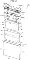
FIG. 2] FIG. 2 is an exploded perspective view of the square secondary battery illustrated inFIG. 1 . - [
FIG. 3] FIG. 3 is a cross-sectional view taken along a line III-III of the square secondary battery illustrated inFIG. 1 . - [
FIG. 4] FIG. 4 is an exploded perspective view of an electrode group illustrated inFIG. 2 . - [
FIG. 5] FIG. 5 is a plan view of the insulating member illustrated inFIGS. 2 and3 . - [
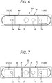
FIG. 6] FIG. 6 is a plan view illustrating a first modification of the insulating member illustrated inFIG. 5 . - [
FIG. 7] FIG. 7 is a plan view illustrating a second modification of the insulating member illustrated inFIG. 5 . - [
FIG. 8] FIG. 8 is an exploded perspective view illustrating a second embodiment of the square secondary battery of the invention. - [
FIG. 9] FIG. 9 is a plan view of the insulating member illustrated inFIG. 8 . - [
FIG. 10] FIG. 10 is a plan view illustrating a modification of the insulating member illustrated inFIG. 8 . - Hereinafter, a first embodiment of a square secondary battery of the invention will be described with reference to the drawings.
-
FIG. 1 is a perspective view of the external appearance of a squaresecondary battery 100 of this embodiment.FIG. 2 is an exploded perspective view of the squaresecondary battery 100 illustrated inFIG. 1 .FIG. 3 is a cross-sectional view taken along a line III-III of the square secondary battery illustrated inFIG. 1 . - The square
secondary battery 100 of this embodiment includes aflat electrode group 40 manufactured by winding positive and negative electrodes, a flat square battery can 11 storing theelectrode group 40, abattery lid 12 sealing an opening 11a of the battery can 11, and aninsulating member 3 which is fixed to thebattery lid 12 and stored in the battery can 11. - While the details are described below, the square
secondary battery 100 of this embodiment has primary features in that astorage member 4 is made of a bag-like insulating sheet, has a volume smaller than that of the battery can 11, and is stored in the battery can 11 to store theelectrode group 40 together with an electrolyte, and in that the insulatingmember 3 adheres to thebattery lid 12 to seal a space formed with respect to thebattery lid 12, and also be bonded to an opening 4a of thestorage member 4 to seal the opening 4a. Hereinafter, a configuration of the squaresecondary battery 100 of this embodiment will be described in detail. - For example, the battery can 11 is manufactured by performing deep processing on a metal material such as an aluminum alloy, and has a flat shape of a bottomed rectangular cylinder which has the
rectangular opening 11a in the upper portion. In other words, the battery can 11 is a housing of a box-liked cuboid, including awide side wall 11b which has a maximum area on both sides in the thickness direction, anarrow side wall 11c which has a relatively small area on both sides in the width direction, abottom wall 11d of a rectangular shape having a long side in the width direction in the bottom. - The
battery lid 12 is, for example, a plate member of a rectangular shape which is manufactured by a metal material such as an aluminum alloy. Thebattery lid 12 is, for example, bonded to the opening 11a of the battery can 11 along the entire peripheral edge by the laser welding, seals the opening 11a of the battery can 11, and forms abattery container 10 together with the battery can 11. Positive and negativeexternal terminals battery lid 12. - The positive and negative
external terminals conductive plate 21, abolt 22, and aconnection terminal 23. Theconductive plate 21, thebolt 22, and theconnection terminal 23 of the positiveexternal terminal 20A are manufactured by aluminum or an aluminum alloy, for example. Theconductive plate 21, thebolt 22, and theconnection terminal 23 of the negativeexternal terminal 20B are manufactured by copper or a copper alloy, for example. Hereinafter, in a case where the positiveexternal terminal 20A and the negativeexternal terminal 20B are not necessarily discriminated in particular, these components will be collectively denoted by theexternal terminal 20. - The
conductive plate 21 is a plate member of a rectangular shape in which the longitudinal direction of thebattery lid 12 is a long-side direction, and disposed on thebattery lid 12 through aninsulating member 2. Theconductive plate 21 includes a constricted portion in the middle in the longitudinal direction, a through hole in one end in the longitudinal direction where thebolt 22 passes through, and a through hole on the other end in the longitudinal direction where theconnection terminal 23 passes through. The head of thebolt 22 is disposed between theinsulating member 2 and theconductive plate 21. Thebolt 22 passes through theconductive plate 21 from the lower side to protrude to the upper side, and electrically connected to theconductive plate 21. Theconnection terminal 23 is a cylindrical member which electrically connects the positive and negativeexternal terminals negative collector plates - A
gas exhaust valve 13 and aliquid injection port 14 are provided in the middle in the longitudinal direction of thebattery lid 12. Thegas exhaust valve 13 is provided to form agroove 13a obtained by forming thebattery lid 12 thin, for example. When an internal pressure of thebattery container 10 rises to exceed a predetermined value, the gas exhaust valve is cleaved to discharge the gas in the battery container so as to serve as a safety valve which lowers the internal pressure of thebattery container 10. Theliquid injection port 14 is used to inject the electrolyte into thebattery container 10, and is sealed by welding aliquid injection plug 15 through the laser welding, for example. - The
insulating member 3 and the positive andnegative collector plates members positive collector plate 30A is, for example, manufactured by aluminum or an aluminum alloy, and thenegative collector plate 30B is, for example, manufactured by copper or a copper alloy. Hereinafter, in a case where thepositive collector plate 30A and thenegative collector plate 30B are not necessarily discriminated in particular, these components will be collectively denoted by thecollector plate 30. - The
insulating member 3 is a plate member of a rectangular shape in which the longitudinal direction of thebattery lid 12 is the long-side direction, and includes a throughhole 3a where theconnection terminal 23 passes through, and an opening 3b through which thegas exhaust valve 13 and theliquid injection port 14 are exposed. In addition, theinsulating member 3 of this embodiment includes anannular bonding portion 3c on the lower surface facing the opening 4a of thestorage member 4. Theannular bonding portion 3c is, for example, bonded to the inside of the opening 4a of thestorage member 4, and seals the opening 4a of thestorage member 4. - The
collector plate 30 includes abase part 31 of a rectangular shape substantially parallel to thebattery lid 12 and a rectangularterminal part 32 which is bent on one side of thebase part 31 and extends along thewide side wall 11b toward thebottom wall 11d of the battery can 11. Thebase part 31 of thecollector plate 30 includes a throughhole 31a where theconnection terminal 23 of the external terminal 20 passes through. Theterminal parts 32 of the positive andnegative collector plates tab parts electrode group 40 by ultrasonic welding or resistance welding, and electrically connected to positive andnegative electrodes FIG. 4 ). - The
external terminal 20, the insulatingmember 2, the insulatingmember 3, and thecollector plate 30 are caulking-fixed to thebattery lid 12 by theconnection terminal 23 of theexternal terminal 20. Specifically, for example, the respective members can be caulking-fixed to thebattery lid 12 according to the following sequence. First, theconnection terminal 23 is inserted to the through hole of theconductive plate 21 of theexternal terminal 20, the through hole of the insulatingmember 2, the through hole of thebattery lid 12, the throughhole 3a of the insulatingmember 3, and the throughhole 31a of thebase part 31 of thecollector plate 30. - Next, one end of the
connection terminal 23 is plastically deformed in the upper surface of theconductive plate 21 of theexternal terminal 20 to widen the diameter, and acaulking part 23a is formed. Similarly, the other end of theconnection terminal 23 is plastically deformed in the lower surface of thebase part 31 of thecollector plate 30 to widen the diameter, and acaulking part 23b is formed. Further, theconnection terminal 23 may be formed such that one end is integrally provided with theconductive plate 21, and thecaulking part 23b is formed only in the other end. Alternatively, the connection terminal may be formed such that the other end is integrally provided with thebase part 31 of thecollector plate 30, and thecaulking part 23a is formed only in the one end. - Therefore, the positive and negative
external terminals member 2 and the insulatingmember 3, and the positive andnegative collector plates battery lid 12 by theconnection terminal 23. In addition, the positive and negativeexternal terminals negative collector plates connection terminal 23, respectively. In addition, theexternal terminal 20 and thecollector plate 30 are electrically insulated from thebattery lid 12 by being fixed to thebattery lid 12 through the insulatingmember 2 and the insulatingmember 3. In addition, the insulatingmember 3 adheres to thebattery lid 12 to seal a space formed with respect to thebattery lid 12. -
FIG. 4 is an exploded perspective view in which part of theelectrode group 40 illustrated inFIG. 2 is developed. - The
electrode group 40 is a flat wound electrode group in which thetab parts negative electrodes electrode group 40 is a wound electrode group which is formed in a flat shape by winding the positive andnegative electrodes separators separators positive electrode 41 and thenegative electrode 42 from each other. The outer side of thenegative electrode 42 wound on the outermost periphery is also wound by theseparator 44. - The
electrode group 40 may be manufactured in the following sequence, for example. First, the starting ends of theseparators separators negative electrodes positive electrode 41 is wound in a state of being disposed on a side near the core from the starting end of thenegative electrode 42. Therefore, in theelectrode group 40 after winding, the starting end of the winding of thepositive electrode 41 is located on a side near the core from the starting end of the winding of thenegative electrode 42. - In this embodiment, the
electrode group 40 is manufactured by winding the positive andnegative electrodes battery lid 12. Theelectrode group 40 includes aflat part 40a in which the positive andnegative electrodes bent part 40b in which the positive andnegative electrodes flat part 40a. Theelectrode group 40 is disposed such that theflat part 40a faces thewide side wall 11b of the battery can 11, and thebent part 40b on both sides of theflat part 40a faces thenarrow side wall 11c of the battery can 11. - The
positive electrode 41 includes apositive electrode foil 41a serving as a positive collector, and apositive mixture layer 41b which is coated on both surfaces of thepositive electrode foil 41a and made of a mixture of active materials for the positive electrode. On one side of thepositive electrode 41 in the width direction, thepositive mixture layer 41b is not formed, and thepositive electrode foil 41a is exposed to form a collector exposed part. The collector exposed part is cut out to form a plurality oftab parts 41c. Thetab part 41c protrudes in the width direction of thepositive electrode 41, and protrudes from the end in the width direction of theseparators tab parts 41c is adjusted such that the plurality oftab parts 41c of thepositive electrode 41 are collectively bound at a position corresponding to theterminal part 32 of thepositive collector plate 30A after winding theelectrode group 40. - The
positive electrode 41 may be manufactured such that a conductive material, a binding agent, and a dispersant are mixed and kneaded with the active material for the positive electrode to produce a mixture of active materials for the positive electrode, and the mixture is coated on both surfaces of thepositive electrode foil 41a except one side in the width direction, and the positive electrode foil is dried, pressed, and cut. As thepositive electrode foil 41a, for example, an aluminum foil having a thickness of 15 µm may be used. The thickness of thepositive mixture layer 41b excluding the thickness of thepositive electrode foil 41a is about 70 µm, for example. - As a material of the mixture of active materials for the positive electrode, for example, nickel cobalt acid lithium (chemical formula: LiNixCoyAl1-x-yO2) having a layered crystal structure of 100 parts by weight, flaky graphite of 10 parts by weight as a conductive material, polyvinylidine fluoride of 10 parts of weight (hereinafter, referred to as PVDF) as a binding agent, and N-methylpyrrolidone (hereinafter, referred to as NMP) as a dispersant may be used. The active material for the positive electrode is not limited to nickel cobalt acid lithium. For example, a layered nickel cobalt lithium manganese (chemical formula: Li(NixCoyMn1-x-y)O2) called a ternary system active material, or a compound oxide of lithium, nickel, cobalt, and manganese obtained by partially replacing or doping with a metal element may be used. In addition, as the active material for the positive electrode, a lithium cobalt oxide or a lithium titanate having a layered crystal structure, and a lithium-metal compound oxide obtained by partially replacing or doping with a metal element may be mixed and used. In order to obtain a high capacitance, a transition metal compound oxide having a large nickel percentage may be preferably used.
- The
negative electrode 42 includes thenegative electrode foil 42a serving as a negative collector, and anegative mixture layer 42b which is made of a mixture of negative materials for the negative electrode coated on both surfaces of thenegative electrode foil 42a. One side of thenegative electrode 42 in the width direction becomes a collector exposed part in which thenegative electrode foil 42a is exposed without thenegative mixture layer 42b, and the collector exposed part is cut out to form thetab part 42c. Thetab part 42c protrudes in the width direction of thenegative electrode 42, and protrudes from the end of theseparators tab parts 42c of thenegative electrode 42 are adjusted in gaps between thetab parts 42c to be collectively bound at a position corresponding to theterminal part 32 of thenegative collector plate 30B after winding theelectrode group 40. - The
negative electrode 42 may be manufactured such that a binding agent and a dispersant are mixed and kneaded with an active material for the negative electrode to produce a mixture of negative materials for the negative electrode, and the mixture is coated on both surfaces of thenegative electrode foil 42a except one side in the width direction, and the negative electrode foil is dried, pressed, and cut. As thenegative electrode foil 42a, for example, a copper foil having a thickness of about 10 µm may be used. The thickness of thenegative mixture layer 42b excluding the thickness of thenegative electrode foil 42a is about 40 µm, for example. - As a material of the mixture of negative materials for the negative electrode, for example, graphitized carbon powder of 100 parts of weight is used as the active material for the negative electrode, a CMC aqueous solution is added as a viscosity-adjusting agent, and after mixing, an SBR of 1 part by weight is added as a binding agent is added and adjusted in viscosity after being kneaded so as to manufacture a negative electrode slurry. The active material for the negative electrode is not limited to one type of material of the graphitized carbon, and lithium ions may be inserted to use a detachable natural graphite, various types of artificial graphites, an amorphous carbon material such as soft carbon or hard carbon, a compound such as Si or Sn (for example, SiO and TiSi2), or a composite of these materials. The particle shape of the active material for the negative electrode is also not particularly limited, and can be appropriately selected from a flaky shape, a circular shape, a fiber shape, or a lump shape. In order to obtain a high capacitance, a heterogenous active material is preferably combined to a graphitized carbon to form an active material mixture layer having a high density.
- Further, a binder used in the positive and negative
mixed layers - In addition, since the
positive electrode 41 and thenegative electrode 42 are overlapped and wound with theseparators positive electrode foil 41a, thenegative electrode foil 42a, and theseparators - The width of the
negative mixture layer 42b of thenegative electrode 42 in the direction of the winding axis A of theelectrode group 40 is made wider than the width of thepositive mixture layer 41b of thepositive electrode 41. In addition, thenegative electrode 42 is wound in the innermost periphery and the outermost periphery of theelectrode group 40. Therefore, thepositive mixture layer 41b is interposed between the negative mixture layers 42b from the innermost periphery to the outermost periphery of theelectrode group 40. - In the
electrode group 40, thetab parts negative electrodes 41 and 42) are bonded to theterminal parts 32 of the positive andnegative collector plates electrode group 40 is electrically connected to theexternal terminal 20 through thecollector plate 30, and fixed to thebattery lid 12 through the insulatingmember 3. Further, in the direction of the winding axis A of theelectrode group 40, the widths of theseparators negative mixture layer 42b, and thetab parts negative electrodes separators separators tab parts - The
electrode group 40 is stored in thestorage member 4 made of the bag-like insulating sheet after being bonded to thecollector plate 30. Thestorage member 4 is, for example, manufactured by an insulating sheet such as polyethylene (PE), polypropylene (PP), polyethylene terephthalate (PET), polytetrafluoroethylene (PTFE), tetrafluoroethylene (PFA), and polyphenylene sulfide (PPS). Thestorage member 4 is formed in a bag shape in which abottom 4b and aside 4c are closed, and theopening 4a is formed in the upper portion. - As illustrated in
FIG. 3 , thestorage member 4 has a volume smaller than the battery can 11, and is stored in the battery can 11 to store theelectrode group 40 together with the electrolyte. Theopening 4a of thestorage member 4 is bonded to the insulatingmember 3 by thermal welding, an adhesive, or a mechanical holding structure, and tightly closed and sealed by the insulatingmember 3. Thestorage member 4 may be formed in a bag shape by the thermal welding to bond the bottom of a cylindrical insulating sheet of which the upper and lower portions are opened. In addition, thestorage member 4 may be formed in a bag shape such that two insulating sheets are overlapped and the side end and the lower end are bonded by the thermal welding. -
FIG. 5 is a plan view of the insulatingmember 3 when viewed from thebottom wall 11d side of the battery can 11 in a direction parallel with the winding axis A of theelectrode group 40. - The insulating
member 3 has theannular bonding portion 3c along the outer shape of theelectrode group 40 when viewed from a direction parallel with the winding axis A of theelectrode group 40. In this embodiment, theannular bonding portion 3c is an outer peripheral surface of aprojection 3d which protrudes from the lower surface of the insulating member 3 (that is, a surface of the insulatingmember 3 facing the inside of the battery can 11) as illustrated inFIG. 3 toward thebottom wall 11d of the battery can 11. - The
annular bonding portion 3c has a predetermined height in a height direction of the square secondary battery 100 (that is, a direction perpendicular to the battery lid 12), and is bonded to the inside of theopening 4a of thestorage member 4 by thermal welding, an adhesive, or a mechanical holding structure, for example. Further, in a case where theprojection 3d is not provided in the insulatingmember 3, the outer peripheral surface of the insulatingmember 3 facing thewide side wall 11b and thenarrow side wall 11c of the battery can 11 may be used as theannular bonding portion 3c. - As illustrated in
FIG. 5 , theannular bonding portion 3c includes a straight part 3c1 along theflat part 40a of theelectrode group 40 and a curved part 3c2 along thebent part 40b of theelectrode group 40 when viewed from a direction parallel with the winding axis A. A width W3 of theannular bonding portion 3c is desirably set to be equal to or more than a width W40 of theelectrode group 40 illustrated inFIG. 2 in the longitudinal direction of thebattery lid 12 from the viewpoint of that thestorage member 4 is made larger than theelectrode group 40 and theelectrode group 40 is easily stored in thestorage member 4. Similarly, a depth D3 of theannular bonding portion 3c along the widthwise direction of thebattery lid 12 is desirably set to be equal to or more than a thickness T40 of theelectrode group 40 illustrated inFIG. 2 . In this embodiment, the width W3 and the depth D3 of theannular bonding portion 3c are slightly larger than the width W40 and the thickness T40 of theelectrode group 40. - On the other hand, in the longitudinal direction of the
battery lid 12, the width W3 of theannular bonding portion 3c is desirably set to be equal to or less than the width W40 of theelectrode group 40 from the viewpoint of that the volume of thestorage member 4 is made small, and the amount of electrolyte stored in thestorage member 4 is made less. Similarly, the depth D3 of theannular bonding portion 3c along the widthwise direction of thebattery lid 12 is desirably equal to or more than the thickness T40 of theelectrode group 40. - In this case, after the
electrode group 40 is stored in thestorage member 4 made of a thermoplastic resin to be a size larger than theelectrode group 40, part or all of thestorage members 4 are desirably heated to be shrunk so as to bond theopening 4a to theannular bonding portion 3c. For example, when theopening 4a of thestorage member 4 is heated and shrunk when being bonding to theannular bonding portion 3c, as illustrated inFIG. 2 , a circumference 4aL of theopening 4a is shrunk more than a circumference 4cL of theside 4c which is the intermediate portion between theopening 4a and the bottom 4b. - The insulating
member 3 includes theopening 3b at a position corresponding to theliquid injection port 14 of thebattery lid 12 inside theannular bonding portion 3c. In addition, the insulatingmember 3 includes theopening 3b at a position corresponding to the gas exhaust valve 13 (the safety valve) inside theannular bonding portion 3c. In this embodiment, theopening 3b of the insulatingmember 3 is formed in a rectangular shape as large as to cover the position corresponding to theliquid injection port 14 and the position corresponding to thegas exhaust valve 13. - As illustrated in
FIGS. 2 and3 , thestorage member 4 is inserted in theopening 11a of the battery can 11 and stored in the battery can 11, in a state where theopening 4a is bonded to the insulatingmember 3, and in a state where theelectrode group 40 is stored in thestorage member 4. Thereafter, thebattery container 10 is configured such that theopening 11a of the battery can 11 is closed by the battery lid 12 (for example, the entire peripheral edge of thebattery lid 12 is welded to the upper end of the battery can 11 by the laser welding) so as to seal theopening 11a of the battery can 11 with thebattery lid 12. - Thereafter, a nonaqueous electrolyte is injected into the
storage member 4 through theliquid injection port 14 of thebattery lid 12 and, for example, the liquid injection plug 15 is bonded to theliquid injection port 14 by the laser welding for sealing. Therefore, thestorage member 4 storing theelectrode group 40 and the electrolyte is tightly closed. As a nonaqueous electrolyte to be injected into the electrolyte, for example, a solution obtained by dissolving lithium hexafluorophosphate (LiPF6) at a concentration of 1 mole/liter in a mixed solution in which ethylene carbonate and dimethyl carbonate are mixed at a volume ratio 1:2 may be used. - With the above configuration, the square
secondary battery 100 of this embodiment accumulates the power supplied from a power generator in theelectrode group 40 through theexternal terminal 20 and thecollector plate 30, and supplies the power accumulated in theelectrode group 40 to an external motor through thecollector plate 30 and theexternal terminal 20. - Hereinafter, an operation of the square
secondary battery 100 of this embodiment will be described. - As described above, the square
secondary battery 100 of this embodiment has a volume smaller than the battery can 11, is stored in the battery can 11, and includes thestorage member 4 made of the bag-like insulating sheet which stores theelectrode group 40 together with the electrolyte. In addition, the insulatingmember 3 adheres to thebattery lid 12 to seal a space formed with respect to thebattery lid 12, and is bonded to theopening 4a of thestorage member 4 so as to seal theopening 4a. - For this reason, when the nonaqueous electrolyte is injected into the
storage member 4 through theliquid injection port 14 of thebattery lid 12, it is prevented that the electrolyte flows out to the space between the battery can 11 and thestorage member 4, and the positive andnegative electrodes electrode group 40 can be sufficiently permeated and impregnated using a relatively less amount of electrolyte compared to the related art. Therefore, according to the squaresecondary battery 100 of this embodiment, it is possible to reduce the amount of electrolyte compared to the related art. In addition, even in a case where the volume of the battery can 11 is increased and thus the space between theelectrode group 40 and the battery can 11 is increased as the squaresecondary battery 100 is increased in capacitance and power, it is possible to suppress that the usage amount of electrolyte is increased. - In addition, the square
secondary battery 100 of this embodiment is configured such that the positive andnegative electrodes battery lid 12, and thetab parts negative electrodes battery lid 12 in the direction of the winding axis A of theelectrode group 40. Therefore, the length of theterminal part 32 of thecollector plate 30 is shortened to make the space in the battery can 11 increase compared to a case where the winding axis A of theelectrode group 40 is disposed in parallel with thebattery lid 12, and the volume of theelectrode group 40 is increased in proportion to the increased space, so that the squaresecondary battery 100 can be made large in capacitance. - In addition, in this embodiment, the insulating
member 3 includes theannular bonding portion 3c along the outer shape of theelectrode group 40 when viewed from a direction parallel with the winding axis A. For this reason, thestorage member 4 bonded to theannular bonding portion 3c can be disposed along the outer shape of theelectrode group 40, and the space between theelectrode group 40 and thestorage member 4 is reduced, so that the amount of electrolyte can be reduced. In addition, in this embodiment, theannular bonding portion 3c is bonded inside theopening 4a of thestorage member 4. Therefore, when theopening 4a of thestorage member 4 is bonded to theannular bonding portion 3c, thestorage member 4 is disposed to be covered on the outside of theannular bonding portion 3c, so that the bonding can be easily and securely performed. - In addition, the
electrode group 40 includes theflat part 40a in which the positive andnegative electrodes bent part 40b in which the positive andnegative electrodes flat part 40a. Then, theannular bonding portion 3c includes the straight part 3c1 along theflat part 40a of theelectrode group 40 and the curved part 3c2 along thebent part 40b of theelectrode group 40 when viewed from a direction parallel with the winding axis A. Therefore, thestorage member 4 bonded to theannular bonding portion 3c can be disposed along theflat part 40a and thebent part 40b of theelectrode group 40. Further, the space between theelectrode group 40 and thestorage member 4 is reduced, so that the amount of electrolyte can be reduced. - In addition, since the insulating
member 3 includes theopening 3b at a position corresponding to theliquid injection port 14 of thebattery lid 12 inside theannular bonding portion 3c, the injection of the electrolyte into thestorage member 4 is not hindered by the insulatingmember 3. In addition, since the insulatingmember 3 includes theopening 3b at a position corresponding to the gas exhaust valve 13 (the safety valve) inside theannular bonding portion 3c, the operation of thegas exhaust valve 13 is not hindered by the insulatingmember 3 when the internal pressure of thebattery container 10 is increased. - The circumference of the
opening 4a of thestorage member 4 is shrunk shorter than that of theside 4c which is an intermediate portion between theopening 4a and the bottom 4b of thestorage member 4. In this case, for example, theopening 4a of thestorage member 4 made of the thermoplastic resin is made larger than theelectrode group 40. Theelectrode group 40 is stored in thestorage member 4, and then put theopening 4a over theannular bonding portion 3c of the insulatingmember 3 and theopening 4a is able to be heated and shrunk. Therefore, it is possible to easily store theelectrode group 40 into thestorage member 4. - As illustrated above, according to the square
secondary battery 100 of this embodiment, the amount of electrolyte can be reduced compared to the related art. Further, it is possible to suppress an increase of the amount of electrolyte even in a case where the space between theelectrode group 40 and the battery can 11 as the battery is increased in capacity and in power. - Further, the description in this embodiment has been given about the insulating
member 3 that is configured to include therectangular opening 3b at the positions corresponding to thegas exhaust valve 13 and theliquid injection port 14, but the invention is not limited to the configuration of the insulatingmember 3. Hereinafter, first and second modifications of the insulatingmember 3 will be described. -
FIG. 6 is a plan view illustrating the first modification of the insulatingmember 3 illustrated inFIG. 5 . An insulatingmember 3A of this modification is configured such that anopening 3e to expose thebattery lid 12 is formed in a space formed with respect to the region where thebase part 31 of thecollector plate 30 is fixed inside theannular bonding portion 3c. Therefore, the area of theopening 3e can be widened, and thegas exhaust valve 13 and theliquid injection port 14 can be disposed more flexibly. In addition, it is possible to reduce the usage amount of material of the insulatingmember 3. -
FIG. 7 is a plan view illustrating the second modification of the insulatingmember 3 illustrated inFIG. 5 . An insulatingmember 3B of this embodiment includes theopening 3e to expose thebattery lid 12, which is formed in a space formed with respect to the region where thebase part 31 of thecollector plate 30 is fixed inside theannular bonding portion 3c, similarly to the insulatingmember 3A of the first modification. Further, the insulatingmember 3B includes arib 3f to reinforce theopening 3e. Therefore, it is possible to improve rigidity and mechanical strength in the vicinity of theopening 3e of the insulatingmember 3B. - Hereinafter, a second embodiment of the square secondary battery of the invention will be described using
FIGS. 8 to 10 with reference toFIG. 4 . -
FIG. 8 is an exploded perspective view of a square secondary battery 100' of this embodiment.FIG. 9 is a plan view of an insulating member 3' of this embodiment when viewed from a direction perpendicular to a winding axis A' of an electrode group 40' illustrated inFIG. 8 .FIG. 10 is a plan view illustrating a modification of the insulating member 3' illustrated inFIG. 9 . - The square secondary battery 100' of this embodiment is different from the square
secondary battery 100 of the first embodiment in that the positive andnegative electrodes battery lid 12, and in the configurations of an external terminal 20' and a collector plate 30'. Since the other configurations of the square secondary battery 100' of this embodiment are similar to those of the squaresecondary battery 100 of the first embodiment, the same portions will be denoted by the same symbols, and the descriptions will be appropriately omitted. - In this embodiment, the tab part is not formed in collector exposed
parts 41c' and 42c' of the positive andnegative electrodes parts 41c' and 42c' are disposed on one and the other ends in the width direction of the positive andnegative electrodes negative electrodes separators part 41c' of thepositive electrode 41 is disposed in one end in the direction of the winding axis A' , and the collector exposedpart 42c' of thenegative electrode 42 is disposed on the other end in the direction of the winding axis A'. - The external terminal 20' includes a welded bonding part 21' of a block shape such as a cuboid shape. In the lower surface of the welded bonding part, there is provided a cylindrical connection terminal similarly to the
connection terminal 23 of the first embodiment. The positive external terminal 20A' is manufactured by aluminum or an aluminum alloy, for example, and the negative external terminal 20B' is manufactured by copper or a copper alloy, for example. - The collector plate 30' includes a base part 31' and a
terminal part 32' similarly to thecollector plate 30 of the first embodiment. The base part 31' of the collector plate 30' is caulking-fixed to thebattery lid 12 by the connection terminal of the external terminal 20' passing through an insulating member 2', thebattery lid 12, the insulating member 3', and the through hole of the base part 31' similarly to thecollector plate 30 of the first embodiment. - The
terminal part 32' of the collector plate 30' is bent on a side of the base part 31' , extends toward thebottom wall 11d along the onewide side wall 11b in the battery can 11, is curved in a thickness direction of theelectrode group 40 on the way, and extends again toward thebottom wall 11d. The lower-side portions curved in theterminal parts 32' of positive andnegative collector plates 30A' and 30B' are bonded to the collector exposedparts 41c' and 42c' bounded at the one end and the other end in the direction of the winding axis A' of the electrode group 40' , for example, by the ultrasonic welding or the resistance welding. - Therefore, the electrode group 40' is fixed to the
battery lid 12 through the collector plate 30' and the insulating member 3' , and is supported in a state where the positive andnegative electrodes battery lid 12. The electrode group 40' is a flat wound electrode group which includes theflat part 40a and thebent part 40b similarly to theelectrode group 40 of the first embodiment. Therefore, the outer shape of the electrode group 40' viewed from a direction perpendicular to the winding axis A' and to thebattery lid 12 is an oblong rectangular shape. As illustrated inFIG. 9 , the insulating member 3' of this embodiment includes anannular bonding portion 3c' of a rectangular shape formed along the outer shape of the electrode group 40' viewed from a direction perpendicular to the winding axis A'. - Similarly to the square
secondary battery 100 of the first embodiment, the square secondary battery 100' of this embodiment includes thestorage member 4 made of the bag-like insulating sheet which has a volume smaller than the battery can 11 and is stored in the battery can 11 to store the electrode group 40' together with the electrolyte. Then, the insulating member 3' adheres to thebattery lid 12 and seals a space formed with respect to thebattery lid 12, and is bonded to theopening 4a of thestorage member 4 to seal theopening 4a. - Therefore, according to the square secondary battery 100' of this embodiment, the amount of electrolyte is reduced similarly to the square
secondary battery 100 of the first embodiment compared to the related art. Further, it is possible to suppress an increase in usage amount of electrolyte even in a case where the space between the electrode group 40' and the battery can 11 as the battery is increased in capacity and in power. In addition, since the insulating member 3' includes theannular bonding portion 3c' of the rectangular shape formed along the external shape of the electrode group 40' viewed from a direction perpendicular to the winding axis A', thestorage member 4 bonded to theannular bonding portion 3c' can be disposed along the outer shape of the electrode group 40', and the space between the electrode group 40' and thestorage member 4 can be reduced, so that the amount of electrolyte can be reduced. - Further, the configuration of the
annular bonding portion 3c' of the insulating member 3' is not limited to the configuration illustrated inFIG. 9 . For example, as described in the modification illustrated inFIG. 10 , an insulatingmember 3A' may include a curved surface r at the corner by forming the corner of theannular bonding portion 3c' of the rectangular shape to have a curved surface shape. Therefore, when theopening 4a of thestorage member 4 is bonded to theannular bonding portion 3c', a gap is hardly generated between theannular bonding portion 3c' and thestorage member 4 in the vicinity of the corner of theannular bonding portion 3c' of the rectangular shape, so that theannular bonding portion 3c' and thestorage member 4 can easily adhere to each other. Therefore, according to this modification, theannular bonding portion 3c' and thestorage member 4 are easily bonded, so that sealability of theopening 4a of thestorage member 4 can be improved. - Hitherto, the embodiments of the invention have been described in detail using the drawings, but the specific configurations are limited to these embodiments. Even when there are variations in design within a scope not departing from the scope of the invention, these variations belong to the invention.
-
- 3, 3A, 3B, 3', 3A': insulating member
- 3b, 3b', 3e: opening
- 3c, 3c': annular bonding portion
- 3f: rib
- 3c1: straight part
- 3c2: curved part
- 4: storage member
- 4a: opening
- 11: battery can
- 11a: opening
- 12: battery lid
- 13: gas exhaust valve (safety valve)
- 14: liquid injection port
- 20, 20': external terminal
- 30, 30': collector plate
- 40, 40': electrode group
- 40a: flat part
- 40b: bent part
- 41: electrode (positive electrode)
- 41c: tab part (collector exposed part)
- 41c': collector exposed part
- 42: electrode (negative electrode)
- 42c: tab part (collector exposed part)
- 42c': collector exposed part
- 100, 100': square secondary battery
- A, A': winding axis
Claims (10)
- A square secondary battery, comprising:a flat electrode group that is manufactured by winding positive and negative electrodes;a flat square battery can that stores the electrode group;a battery lid that seals an opening of the battery can;an insulating member that is fixed to the battery lid and stored in the battery can; anda storage member made of a bag-like insulating sheet that has a volume smaller than the battery can, and is stored in the battery can and stores the electrode group together with an electrolyte,wherein the insulating member adheres to the battery lid to seal a space formed with respect to the battery lid, and is bonded to an opening of the storage member together to seal the opening.
- The square secondary battery according to claim 1,
wherein the electrode group is configured to wind the positive and negative electrodes around a winding axis perpendicular to the battery lid, and
wherein the insulating member includes an annular bonding portion that is formed along an outer shape of the electrode group when viewed from a direction parallel with the winding axis. - The square secondary battery according to claim 2,
wherein the electrode group includes a flat part in which the positive and negative electrodes are flatly wound, and a bent part in which the positive and negative electrodes are bent and wound on both sides of the flat part, and
wherein the annular bonding portion includes a straight part formed along the flat part and a curved part formed along the bent part when viewed from a direction parallel with the winding axis. - The square secondary battery according to claim 1,
wherein the electrode group is configured to wind the positive and negative electrodes around a winding axis in parallel with the battery lid, and
wherein the insulating member includes an annular bonding portion of a rectangular shape formed along an outer shape of the electrode group when viewed from a direction perpendicular to the winding axis. - The square secondary battery according to claim 4,
wherein the insulating member is configured such that a corner of the annular bonding portion of the rectangular shape is formed in a curved surface shape. - The square secondary battery according to any one of claims 2 to 5,
wherein the battery lid includes a liquid injection port through which the electrolyte is injected, and
wherein the insulating member includes an opening at a position corresponding to the liquid injection port inside the annular bonding portion. - The square secondary battery according to claim 6,
wherein the battery lid includes a safety valve that is opened when an internal pressure of the battery can rises up to a predetermined value, and
wherein the insulating member includes an opening at a position corresponding to the safety valve inside the annular bonding portion. - The square secondary battery according to claim 7,
wherein the insulating member includes a rib that reinforces the opening of the insulating member. - The square secondary battery according to any one of claims 1 to 5,
wherein a circumference of the opening of the storage member is reduced more than that of an intermediate portion between the opening and a bottom of the storage member. - The square secondary battery according to any one of claims 1 to 5, further comprising:an external terminal that is provided in the battery lid; anda collector plate that is connected to the external terminal and fixed to the battery lid through the insulating member,wherein the electrode group is configured such that collector exposed parts of the positive and negative electrodes are bonded to the collector plate, and electrically connected to the external terminal through the collector plate and fixed to the battery lid.
Applications Claiming Priority (2)
| Application Number | Priority Date | Filing Date | Title |
|---|---|---|---|
| JP2014245942 | 2014-12-04 | ||
| PCT/JP2015/081248 WO2016088506A1 (en) | 2014-12-04 | 2015-11-06 | Rectangular secondary battery |
Publications (3)
| Publication Number | Publication Date |
|---|---|
| EP3229305A1 true EP3229305A1 (en) | 2017-10-11 |
| EP3229305A4 EP3229305A4 (en) | 2018-08-15 |
| EP3229305B1 EP3229305B1 (en) | 2019-05-08 |
Family
ID=56091458
Family Applications (1)
| Application Number | Title | Priority Date | Filing Date |
|---|---|---|---|
| EP15864473.2A Active EP3229305B1 (en) | 2014-12-04 | 2015-11-06 | Rectangular secondary battery |
Country Status (5)
| Country | Link |
|---|---|
| US (1) | US20170324070A1 (en) |
| EP (1) | EP3229305B1 (en) |
| JP (1) | JP6328271B2 (en) |
| CN (1) | CN107078337B (en) |
| WO (1) | WO2016088506A1 (en) |
Cited By (4)
| Publication number | Priority date | Publication date | Assignee | Title |
|---|---|---|---|---|
| JP2016081743A (en) * | 2014-10-17 | 2016-05-16 | 株式会社豊田自動織機 | Power storage device |
| WO2018094074A3 (en) * | 2016-11-16 | 2018-09-27 | Pacesetter, Inc. | Battery with enhanced resistance to dendrite formation |
| EP3709422A4 (en) * | 2017-11-07 | 2021-08-25 | Kabushiki Kaisha Toshiba | BATTERY AND BATTERY PACK |
| EP4618259A4 (en) * | 2023-02-16 | 2026-03-11 | Contemporary Amperex Technology Hong Kong Ltd | BATTERY CELL, BATTERY, ELECTRICAL DEVICE AND METHOD FOR MAKING A BATTERY CELL |
Families Citing this family (14)
| Publication number | Priority date | Publication date | Assignee | Title |
|---|---|---|---|---|
| JP6825567B2 (en) * | 2015-09-18 | 2021-02-03 | 株式会社Gsユアサ | Power storage element |
| WO2018021372A1 (en) * | 2016-07-29 | 2018-02-01 | 三洋電機株式会社 | Secondary battery |
| KR102348680B1 (en) * | 2017-01-26 | 2022-01-06 | 삼성에스디아이 주식회사 | Rechargeable battery |
| JP7055648B2 (en) * | 2018-01-26 | 2022-04-18 | 三洋電機株式会社 | Power storage device |
| WO2020066240A1 (en) * | 2018-09-26 | 2020-04-02 | パナソニック株式会社 | Secondary battery |
| JP7119837B2 (en) * | 2018-09-26 | 2022-08-17 | 株式会社Gsユアサ | Storage element |
| JP7039728B2 (en) * | 2018-11-26 | 2022-03-22 | 株式会社東芝 | Closure assembly, batteries and battery pack |
| JP7118242B2 (en) * | 2019-03-20 | 2022-08-15 | ビークルエナジージャパン株式会社 | secondary battery |
| JP7240611B2 (en) * | 2019-11-19 | 2023-03-16 | トヨタ自動車株式会社 | secondary battery |
| CN114946061A (en) * | 2020-02-17 | 2022-08-26 | 株式会社村田制作所 | Secondary battery, electronic device, and electric power tool |
| JP7472317B2 (en) * | 2020-12-14 | 2024-04-22 | 株式会社東芝 | battery |
| JP7556836B2 (en) * | 2021-09-21 | 2024-09-26 | プライムプラネットエナジー&ソリューションズ株式会社 | battery |
| CN116438701A (en) * | 2021-09-30 | 2023-07-14 | 宁德时代新能源科技股份有限公司 | A battery cell, a battery, an electrical device, and a manufacturing method and equipment for a battery cell |
| KR20260037538A (en) * | 2024-09-10 | 2026-03-17 | 삼성에스디아이 주식회사 | Secondary battery with electrolyte impregnation path shortened and manufacturing method thereof |
Family Cites Families (8)
| Publication number | Priority date | Publication date | Assignee | Title |
|---|---|---|---|---|
| KR101222309B1 (en) * | 2010-12-29 | 2013-01-15 | 로베르트 보쉬 게엠베하 | Secondary battery |
| JP5777093B2 (en) * | 2011-06-30 | 2015-09-09 | 株式会社東芝 | Secondary battery and method for manufacturing secondary battery |
| JP5856858B2 (en) * | 2012-01-27 | 2016-02-10 | 三洋電機株式会社 | Method for manufacturing prismatic secondary battery |
| JP6040554B2 (en) * | 2012-03-30 | 2016-12-07 | 株式会社Gsユアサ | Electricity storage element |
| JP2013251119A (en) * | 2012-05-31 | 2013-12-12 | Hitachi Vehicle Energy Ltd | Square secondary battery |
| DE102013200555A1 (en) * | 2013-01-16 | 2014-07-17 | Robert Bosch Gmbh | Method for manufacturing battery cell for battery module or battery system of motor car, involves introducing liquid sealed in electrode coil into metal casing and closing metal casing by inserting cover assembly to casing |
| JP2014199780A (en) * | 2013-03-29 | 2014-10-23 | 株式会社リチウムエナジージャパン | Electricity storage element |
| KR102201306B1 (en) * | 2014-06-17 | 2021-01-11 | 삼성에스디아이 주식회사 | Secondary Battery |
-
2015
- 2015-11-06 EP EP15864473.2A patent/EP3229305B1/en active Active
- 2015-11-06 WO PCT/JP2015/081248 patent/WO2016088506A1/en not_active Ceased
- 2015-11-06 CN CN201580056379.0A patent/CN107078337B/en active Active
- 2015-11-06 US US15/525,106 patent/US20170324070A1/en not_active Abandoned
- 2015-11-06 JP JP2016562357A patent/JP6328271B2/en active Active
Cited By (9)
| Publication number | Priority date | Publication date | Assignee | Title |
|---|---|---|---|---|
| JP2016081743A (en) * | 2014-10-17 | 2016-05-16 | 株式会社豊田自動織機 | Power storage device |
| WO2018094074A3 (en) * | 2016-11-16 | 2018-09-27 | Pacesetter, Inc. | Battery with enhanced resistance to dendrite formation |
| US10727454B2 (en) | 2016-11-16 | 2020-07-28 | Pacesetter, Inc. | Battery with enhanced resistance to dendrite formation |
| US10868283B2 (en) | 2016-11-16 | 2020-12-15 | Pacesetter, Inc. | Battery with enhanced resistance to dendrite formation |
| US10964922B2 (en) | 2016-11-16 | 2021-03-30 | Pacesetter, Inc. | Battery with enhanced resistance to dendrite formation |
| US10964921B2 (en) | 2016-11-16 | 2021-03-30 | Pacesetter, Inc. | Battery with enhanced resistance to dendrite formation |
| US11735711B2 (en) | 2016-11-16 | 2023-08-22 | Pacesetter, Inc. | Battery with enhanced resistance to dendrite formation |
| EP3709422A4 (en) * | 2017-11-07 | 2021-08-25 | Kabushiki Kaisha Toshiba | BATTERY AND BATTERY PACK |
| EP4618259A4 (en) * | 2023-02-16 | 2026-03-11 | Contemporary Amperex Technology Hong Kong Ltd | BATTERY CELL, BATTERY, ELECTRICAL DEVICE AND METHOD FOR MAKING A BATTERY CELL |
Also Published As
| Publication number | Publication date |
|---|---|
| JPWO2016088506A1 (en) | 2017-07-27 |
| US20170324070A1 (en) | 2017-11-09 |
| WO2016088506A1 (en) | 2016-06-09 |
| EP3229305A4 (en) | 2018-08-15 |
| EP3229305B1 (en) | 2019-05-08 |
| CN107078337A (en) | 2017-08-18 |
| JP6328271B2 (en) | 2018-05-23 |
| CN107078337B (en) | 2019-10-29 |
Similar Documents
| Publication | Publication Date | Title |
|---|---|---|
| EP3229305B1 (en) | Rectangular secondary battery | |
| JP6739522B2 (en) | Storage element | |
| JP6410833B2 (en) | Prismatic secondary battery | |
| JP6446239B2 (en) | Secondary battery | |
| CN103748733B (en) | Lithium rechargeable battery and its manufacture method | |
| JP5779562B2 (en) | Square battery | |
| CN108028350B (en) | Electrochemical energy storage device | |
| JP6913766B2 (en) | Positive electrode for lithium ion secondary battery and lithium ion secondary battery using it | |
| JP2016143618A (en) | Rectangular secondary battery | |
| JP2016178053A (en) | Prismatic secondary battery | |
| JP6216203B2 (en) | Winding type secondary battery | |
| JP2016139532A (en) | Rectangular secondary battery | |
| JP2019169331A (en) | Power storage element | |
| JP6978500B2 (en) | Secondary battery | |
| JP2018056017A (en) | Electricity storage element | |
| JP6382336B2 (en) | Prismatic secondary battery | |
| JP7065965B2 (en) | Secondary battery | |
| JP2015065048A (en) | Square secondary battery and battery pack | |
| WO2022163636A1 (en) | Power storage element | |
| CN117157822A (en) | Secondary battery | |
| JP2022116701A (en) | Storage element | |
| JP6504994B2 (en) | Square storage element | |
| JP6493949B2 (en) | Lithium ion secondary battery | |
| JP2015138621A (en) | lithium ion secondary battery | |
| JP2018147618A (en) | Power storage element |
Legal Events
| Date | Code | Title | Description |
|---|---|---|---|
| STAA | Information on the status of an ep patent application or granted ep patent |
Free format text: STATUS: THE INTERNATIONAL PUBLICATION HAS BEEN MADE |
|
| PUAI | Public reference made under article 153(3) epc to a published international application that has entered the european phase |
Free format text: ORIGINAL CODE: 0009012 |
|
| STAA | Information on the status of an ep patent application or granted ep patent |
Free format text: STATUS: REQUEST FOR EXAMINATION WAS MADE |
|
| 17P | Request for examination filed |
Effective date: 20170704 |
|
| A4 | Supplementary search report drawn up and despatched |
Effective date: 20170901 |
|
| AK | Designated contracting states |
Kind code of ref document: A1 Designated state(s): AL AT BE BG CH CY CZ DE DK EE ES FI FR GB GR HR HU IE IS IT LI LT LU LV MC MK MT NL NO PL PT RO RS SE SI SK SM TR |
|
| AX | Request for extension of the european patent |
Extension state: BA ME |
|
| DAV | Request for validation of the european patent (deleted) | ||
| DAX | Request for extension of the european patent (deleted) | ||
| RA4 | Supplementary search report drawn up and despatched (corrected) |
Effective date: 20180711 |
|
| GRAP | Despatch of communication of intention to grant a patent |
Free format text: ORIGINAL CODE: EPIDOSNIGR1 |
|
| STAA | Information on the status of an ep patent application or granted ep patent |
Free format text: STATUS: GRANT OF PATENT IS INTENDED |
|
| INTG | Intention to grant announced |
Effective date: 20190118 |
|
| GRAS | Grant fee paid |
Free format text: ORIGINAL CODE: EPIDOSNIGR3 |
|
| GRAA | (expected) grant |
Free format text: ORIGINAL CODE: 0009210 |
|
| STAA | Information on the status of an ep patent application or granted ep patent |
Free format text: STATUS: THE PATENT HAS BEEN GRANTED |
|
| AK | Designated contracting states |
Kind code of ref document: B1 Designated state(s): AL AT BE BG CH CY CZ DE DK EE ES FI FR GB GR HR HU IE IS IT LI LT LU LV MC MK MT NL NO PL PT RO RS SE SI SK SM TR |
|
| RAP1 | Party data changed (applicant data changed or rights of an application transferred) |
Owner name: HITACHI AUTOMOTIVE SYSTEMS, LTD. |
|
| REG | Reference to a national code |
Ref country code: GB Ref legal event code: FG4D |
|
| REG | Reference to a national code |
Ref country code: CH Ref legal event code: EP Ref country code: AT Ref legal event code: REF Ref document number: 1131657 Country of ref document: AT Kind code of ref document: T Effective date: 20190515 |
|
| REG | Reference to a national code |
Ref country code: IE Ref legal event code: FG4D |
|
| REG | Reference to a national code |
Ref country code: DE Ref legal event code: R096 Ref document number: 602015030135 Country of ref document: DE |
|
| REG | Reference to a national code |
Ref country code: NL Ref legal event code: MP Effective date: 20190508 |
|
| REG | Reference to a national code |
Ref country code: LT Ref legal event code: MG4D |
|
| PG25 | Lapsed in a contracting state [announced via postgrant information from national office to epo] |
Ref country code: NO Free format text: LAPSE BECAUSE OF FAILURE TO SUBMIT A TRANSLATION OF THE DESCRIPTION OR TO PAY THE FEE WITHIN THE PRESCRIBED TIME-LIMIT Effective date: 20190808 Ref country code: HR Free format text: LAPSE BECAUSE OF FAILURE TO SUBMIT A TRANSLATION OF THE DESCRIPTION OR TO PAY THE FEE WITHIN THE PRESCRIBED TIME-LIMIT Effective date: 20190508 Ref country code: NL Free format text: LAPSE BECAUSE OF FAILURE TO SUBMIT A TRANSLATION OF THE DESCRIPTION OR TO PAY THE FEE WITHIN THE PRESCRIBED TIME-LIMIT Effective date: 20190508 Ref country code: LT Free format text: LAPSE BECAUSE OF FAILURE TO SUBMIT A TRANSLATION OF THE DESCRIPTION OR TO PAY THE FEE WITHIN THE PRESCRIBED TIME-LIMIT Effective date: 20190508 Ref country code: AL Free format text: LAPSE BECAUSE OF FAILURE TO SUBMIT A TRANSLATION OF THE DESCRIPTION OR TO PAY THE FEE WITHIN THE PRESCRIBED TIME-LIMIT Effective date: 20190508 Ref country code: PT Free format text: LAPSE BECAUSE OF FAILURE TO SUBMIT A TRANSLATION OF THE DESCRIPTION OR TO PAY THE FEE WITHIN THE PRESCRIBED TIME-LIMIT Effective date: 20190908 Ref country code: SE Free format text: LAPSE BECAUSE OF FAILURE TO SUBMIT A TRANSLATION OF THE DESCRIPTION OR TO PAY THE FEE WITHIN THE PRESCRIBED TIME-LIMIT Effective date: 20190508 Ref country code: FI Free format text: LAPSE BECAUSE OF FAILURE TO SUBMIT A TRANSLATION OF THE DESCRIPTION OR TO PAY THE FEE WITHIN THE PRESCRIBED TIME-LIMIT Effective date: 20190508 |
|
| PG25 | Lapsed in a contracting state [announced via postgrant information from national office to epo] |
Ref country code: BG Free format text: LAPSE BECAUSE OF FAILURE TO SUBMIT A TRANSLATION OF THE DESCRIPTION OR TO PAY THE FEE WITHIN THE PRESCRIBED TIME-LIMIT Effective date: 20190808 Ref country code: GR Free format text: LAPSE BECAUSE OF FAILURE TO SUBMIT A TRANSLATION OF THE DESCRIPTION OR TO PAY THE FEE WITHIN THE PRESCRIBED TIME-LIMIT Effective date: 20190809 Ref country code: LV Free format text: LAPSE BECAUSE OF FAILURE TO SUBMIT A TRANSLATION OF THE DESCRIPTION OR TO PAY THE FEE WITHIN THE PRESCRIBED TIME-LIMIT Effective date: 20190508 Ref country code: RS Free format text: LAPSE BECAUSE OF FAILURE TO SUBMIT A TRANSLATION OF THE DESCRIPTION OR TO PAY THE FEE WITHIN THE PRESCRIBED TIME-LIMIT Effective date: 20190508 |
|
| REG | Reference to a national code |
Ref country code: AT Ref legal event code: MK05 Ref document number: 1131657 Country of ref document: AT Kind code of ref document: T Effective date: 20190508 |
|
| PG25 | Lapsed in a contracting state [announced via postgrant information from national office to epo] |
Ref country code: SK Free format text: LAPSE BECAUSE OF FAILURE TO SUBMIT A TRANSLATION OF THE DESCRIPTION OR TO PAY THE FEE WITHIN THE PRESCRIBED TIME-LIMIT Effective date: 20190508 Ref country code: RO Free format text: LAPSE BECAUSE OF FAILURE TO SUBMIT A TRANSLATION OF THE DESCRIPTION OR TO PAY THE FEE WITHIN THE PRESCRIBED TIME-LIMIT Effective date: 20190508 Ref country code: CZ Free format text: LAPSE BECAUSE OF FAILURE TO SUBMIT A TRANSLATION OF THE DESCRIPTION OR TO PAY THE FEE WITHIN THE PRESCRIBED TIME-LIMIT Effective date: 20190508 Ref country code: DK Free format text: LAPSE BECAUSE OF FAILURE TO SUBMIT A TRANSLATION OF THE DESCRIPTION OR TO PAY THE FEE WITHIN THE PRESCRIBED TIME-LIMIT Effective date: 20190508 Ref country code: AT Free format text: LAPSE BECAUSE OF FAILURE TO SUBMIT A TRANSLATION OF THE DESCRIPTION OR TO PAY THE FEE WITHIN THE PRESCRIBED TIME-LIMIT Effective date: 20190508 Ref country code: EE Free format text: LAPSE BECAUSE OF FAILURE TO SUBMIT A TRANSLATION OF THE DESCRIPTION OR TO PAY THE FEE WITHIN THE PRESCRIBED TIME-LIMIT Effective date: 20190508 |
|
| REG | Reference to a national code |
Ref country code: DE Ref legal event code: R097 Ref document number: 602015030135 Country of ref document: DE |
|
| PG25 | Lapsed in a contracting state [announced via postgrant information from national office to epo] |
Ref country code: SM Free format text: LAPSE BECAUSE OF FAILURE TO SUBMIT A TRANSLATION OF THE DESCRIPTION OR TO PAY THE FEE WITHIN THE PRESCRIBED TIME-LIMIT Effective date: 20190508 Ref country code: IT Free format text: LAPSE BECAUSE OF FAILURE TO SUBMIT A TRANSLATION OF THE DESCRIPTION OR TO PAY THE FEE WITHIN THE PRESCRIBED TIME-LIMIT Effective date: 20190508 |
|
| REG | Reference to a national code |
Ref country code: DE Ref legal event code: R082 Ref document number: 602015030135 Country of ref document: DE Representative=s name: MERH-IP MATIAS ERNY REICHL HOFFMANN PATENTANWA, DE Ref country code: DE Ref legal event code: R081 Ref document number: 602015030135 Country of ref document: DE Owner name: VEHICLE ENERGY JAPAN INC., HITACHINAKA-SHI, JP Free format text: FORMER OWNER: HITACHI AUTOMOTIVE SYSTEMS, LTD., HITACHINAKA-SHI, IBARAKI, JP |
|
| PLBE | No opposition filed within time limit |
Free format text: ORIGINAL CODE: 0009261 |
|
| STAA | Information on the status of an ep patent application or granted ep patent |
Free format text: STATUS: NO OPPOSITION FILED WITHIN TIME LIMIT |
|
| PG25 | Lapsed in a contracting state [announced via postgrant information from national office to epo] |
Ref country code: TR Free format text: LAPSE BECAUSE OF FAILURE TO SUBMIT A TRANSLATION OF THE DESCRIPTION OR TO PAY THE FEE WITHIN THE PRESCRIBED TIME-LIMIT Effective date: 20190508 |
|
| 26N | No opposition filed |
Effective date: 20200211 |
|
| PG25 | Lapsed in a contracting state [announced via postgrant information from national office to epo] |
Ref country code: PL Free format text: LAPSE BECAUSE OF FAILURE TO SUBMIT A TRANSLATION OF THE DESCRIPTION OR TO PAY THE FEE WITHIN THE PRESCRIBED TIME-LIMIT Effective date: 20190508 |
|
| PG25 | Lapsed in a contracting state [announced via postgrant information from national office to epo] |
Ref country code: SI Free format text: LAPSE BECAUSE OF FAILURE TO SUBMIT A TRANSLATION OF THE DESCRIPTION OR TO PAY THE FEE WITHIN THE PRESCRIBED TIME-LIMIT Effective date: 20190508 |
|
| REG | Reference to a national code |
Ref country code: CH Ref legal event code: PL |
|
| PG25 | Lapsed in a contracting state [announced via postgrant information from national office to epo] |
Ref country code: LI Free format text: LAPSE BECAUSE OF NON-PAYMENT OF DUE FEES Effective date: 20191130 Ref country code: MC Free format text: LAPSE BECAUSE OF FAILURE TO SUBMIT A TRANSLATION OF THE DESCRIPTION OR TO PAY THE FEE WITHIN THE PRESCRIBED TIME-LIMIT Effective date: 20190508 Ref country code: CH Free format text: LAPSE BECAUSE OF NON-PAYMENT OF DUE FEES Effective date: 20191130 Ref country code: LU Free format text: LAPSE BECAUSE OF NON-PAYMENT OF DUE FEES Effective date: 20191106 |
|
| REG | Reference to a national code |
Ref country code: BE Ref legal event code: MM Effective date: 20191130 |
|
| GBPC | Gb: european patent ceased through non-payment of renewal fee |
Effective date: 20191106 |
|
| PG25 | Lapsed in a contracting state [announced via postgrant information from national office to epo] |
Ref country code: ES Free format text: LAPSE BECAUSE OF FAILURE TO SUBMIT A TRANSLATION OF THE DESCRIPTION OR TO PAY THE FEE WITHIN THE PRESCRIBED TIME-LIMIT Effective date: 20190508 Ref country code: IE Free format text: LAPSE BECAUSE OF NON-PAYMENT OF DUE FEES Effective date: 20191106 Ref country code: GB Free format text: LAPSE BECAUSE OF NON-PAYMENT OF DUE FEES Effective date: 20191106 |
|
| PG25 | Lapsed in a contracting state [announced via postgrant information from national office to epo] |
Ref country code: BE Free format text: LAPSE BECAUSE OF NON-PAYMENT OF DUE FEES Effective date: 20191130 |
|
| PG25 | Lapsed in a contracting state [announced via postgrant information from national office to epo] |
Ref country code: CY Free format text: LAPSE BECAUSE OF FAILURE TO SUBMIT A TRANSLATION OF THE DESCRIPTION OR TO PAY THE FEE WITHIN THE PRESCRIBED TIME-LIMIT Effective date: 20190508 |
|
| PG25 | Lapsed in a contracting state [announced via postgrant information from national office to epo] |
Ref country code: IS Free format text: LAPSE BECAUSE OF FAILURE TO SUBMIT A TRANSLATION OF THE DESCRIPTION OR TO PAY THE FEE WITHIN THE PRESCRIBED TIME-LIMIT Effective date: 20190908 |
|
| PG25 | Lapsed in a contracting state [announced via postgrant information from national office to epo] |
Ref country code: HU Free format text: LAPSE BECAUSE OF FAILURE TO SUBMIT A TRANSLATION OF THE DESCRIPTION OR TO PAY THE FEE WITHIN THE PRESCRIBED TIME-LIMIT; INVALID AB INITIO Effective date: 20151106 Ref country code: MT Free format text: LAPSE BECAUSE OF FAILURE TO SUBMIT A TRANSLATION OF THE DESCRIPTION OR TO PAY THE FEE WITHIN THE PRESCRIBED TIME-LIMIT Effective date: 20190508 |
|
| PG25 | Lapsed in a contracting state [announced via postgrant information from national office to epo] |
Ref country code: MK Free format text: LAPSE BECAUSE OF FAILURE TO SUBMIT A TRANSLATION OF THE DESCRIPTION OR TO PAY THE FEE WITHIN THE PRESCRIBED TIME-LIMIT Effective date: 20190508 |
|
| PGFP | Annual fee paid to national office [announced via postgrant information from national office to epo] |
Ref country code: FR Payment date: 20250930 Year of fee payment: 11 |
|
| PGFP | Annual fee paid to national office [announced via postgrant information from national office to epo] |
Ref country code: DE Payment date: 20250930 Year of fee payment: 11 |