EP3229255B1 - Temperature-dependent switch - Google Patents
Temperature-dependent switch Download PDFInfo
- Publication number
- EP3229255B1 EP3229255B1 EP17172229.1A EP17172229A EP3229255B1 EP 3229255 B1 EP3229255 B1 EP 3229255B1 EP 17172229 A EP17172229 A EP 17172229A EP 3229255 B1 EP3229255 B1 EP 3229255B1
- Authority
- EP
- European Patent Office
- Prior art keywords
- plunger
- temperature
- snap
- spring element
- spring
- Prior art date
- Legal status (The legal status is an assumption and is not a legal conclusion. Google has not performed a legal analysis and makes no representation as to the accuracy of the status listed.)
- Active
Links
- 230000001419 dependent effect Effects 0.000 title claims description 39
- 239000012212 insulator Substances 0.000 description 19
- 230000013011 mating Effects 0.000 description 11
- 230000007246 mechanism Effects 0.000 description 9
- 230000008878 coupling Effects 0.000 description 7
- 238000010168 coupling process Methods 0.000 description 7
- 238000005859 coupling reaction Methods 0.000 description 7
- 230000004044 response Effects 0.000 description 7
- 238000010438 heat treatment Methods 0.000 description 6
- 230000008901 benefit Effects 0.000 description 3
- 230000006835 compression Effects 0.000 description 3
- 238000007906 compression Methods 0.000 description 3
- 238000000034 method Methods 0.000 description 3
- 230000008569 process Effects 0.000 description 3
- 238000013021 overheating Methods 0.000 description 2
- 230000005540 biological transmission Effects 0.000 description 1
- 230000015572 biosynthetic process Effects 0.000 description 1
- 238000010276 construction Methods 0.000 description 1
- 239000002184 metal Substances 0.000 description 1
- 230000002093 peripheral effect Effects 0.000 description 1
- 230000007704 transition Effects 0.000 description 1
- 230000001960 triggered effect Effects 0.000 description 1
Images


Classifications
-
- H—ELECTRICITY
- H01—ELECTRIC ELEMENTS
- H01H—ELECTRIC SWITCHES; RELAYS; SELECTORS; EMERGENCY PROTECTIVE DEVICES
- H01H37/00—Thermally-actuated switches
- H01H37/02—Details
- H01H37/32—Thermally-sensitive members
- H01H37/52—Thermally-sensitive members actuated due to deflection of bimetallic element
- H01H37/54—Thermally-sensitive members actuated due to deflection of bimetallic element wherein the bimetallic element is inherently snap acting
- H01H37/5427—Thermally-sensitive members actuated due to deflection of bimetallic element wherein the bimetallic element is inherently snap acting encapsulated in sealed miniaturised housing
-
- H—ELECTRICITY
- H01—ELECTRIC ELEMENTS
- H01H—ELECTRIC SWITCHES; RELAYS; SELECTORS; EMERGENCY PROTECTIVE DEVICES
- H01H1/00—Contacts
- H01H1/12—Contacts characterised by the manner in which co-operating contacts engage
- H01H1/14—Contacts characterised by the manner in which co-operating contacts engage by abutting
- H01H1/24—Contacts characterised by the manner in which co-operating contacts engage by abutting with resilient mounting
- H01H1/26—Contacts characterised by the manner in which co-operating contacts engage by abutting with resilient mounting with spring blade support
-
- H—ELECTRICITY
- H01—ELECTRIC ELEMENTS
- H01H—ELECTRIC SWITCHES; RELAYS; SELECTORS; EMERGENCY PROTECTIVE DEVICES
- H01H37/00—Thermally-actuated switches
- H01H37/02—Details
- H01H37/32—Thermally-sensitive members
- H01H37/52—Thermally-sensitive members actuated due to deflection of bimetallic element
- H01H37/54—Thermally-sensitive members actuated due to deflection of bimetallic element wherein the bimetallic element is inherently snap acting
- H01H2037/549—Details of movement transmission between bimetallic snap element and contact
-
- H—ELECTRICITY
- H01—ELECTRIC ELEMENTS
- H01H—ELECTRIC SWITCHES; RELAYS; SELECTORS; EMERGENCY PROTECTIVE DEVICES
- H01H37/00—Thermally-actuated switches
- H01H37/02—Details
- H01H37/32—Thermally-sensitive members
- H01H37/52—Thermally-sensitive members actuated due to deflection of bimetallic element
- H01H37/54—Thermally-sensitive members actuated due to deflection of bimetallic element wherein the bimetallic element is inherently snap acting
- H01H37/5418—Thermally-sensitive members actuated due to deflection of bimetallic element wherein the bimetallic element is inherently snap acting using cantilevered bimetallic snap elements
Definitions
- the present invention relates to a temperature-dependent switch with a first and a second external connection, the first and second external connection being fixed to an insulator body, the first and second external connection being designed as a first or second connection plate, the two connection plates protruding from the insulator body, and the insulator body is arranged in a housing, having a stationary contact part which is electrically conductively connected to the first external connection, a movable contact part which cooperates with the stationary contact part and is fastened to a spring part which is electrically conductively connected to the second external connection, and which the movable contact part presses against the stationary contact part, a bimetallic part and a plunger arranged between the bimetallic part and the spring part, the bimetallic part exerting compressive forces on the spring part via the plunger when a switching temperature is exceeded and dadu rch the movable contact part lifts off the stationary contact part, and wherein the spring part has a first and a second leg, the movable contact part is fixed to the first
- Such a switch is from EP 2 511 930 A1 known.
- the well-known switch is a temperature protection switch, in which the switching movement of a bimetallic disc transmits compressive forces via a plunger to a current-carrying spring part, which acts as a closing spring here.
- the closing spring carries a movable contact part which presses it against a stationary contact part when the switch is closed.
- the stationary contact part and closing spring are each connected to a connecting plate.
- the two connecting plates are fixed to an insulator body, from which they protrude laterally.
- the temperature protection switch has a flat housing from which the two connection plates protrude as external connections.
- Such temperature-dependent switches are used in a known manner to protect electrical devices from overheating.
- the switch is electrically connected in series with the device to be protected via its two external connections and is mechanically arranged on the device in such a way that it is thermally connected to it.
- a temperature-dependent switching mechanism consisting of a spring snap-action disc, a bimetallic snap-action disc and a movable contact part is arranged in a housing, which when the switch is closed is in contact with a stationary contact part on the inside of the upper part, which is plated through to a first connection on the upper part on the outside.
- the conductive lower part serves as the second connection.
- the operating current of the device to be protected flows through the two contact parts and the spring snap-in disc into the lower part.
- the one from the DE 44 28 226 C1 known switch is provided with a heating resistor which is electrically arranged in series with the external connections and ensures a current-dependent switching function.
- the operating current of the device to be protected thus flows constantly through this heating resistor, which can be dimensioned in such a way that when a certain operating current is exceeded, it ensures that the bimetallic snap-action disc is heated to a temperature above its response temperature, so that the switch opens at an increased operating current before the device to be protected has overheated.
- the circuit is closed and the device to be protected is supplied with power via the switch. If the temperature rises above a permissible value, either as a result of an excessively high operating current or as a result of the device to be protected being overheated, the bimetal snap-action disc deforms, causing the spring snap-action disc to move from its first stable geometric configuration in which it holds the moving contact part presses against the stationary contact part, jumps into its second stable geometric configuration, in which it lifts the movable contact part from the stationary contact part. The switch is opened and the power supply to the device to be protected is interrupted.
- the now de-energized device can then cool down again.
- the switch that is thermally coupled to the device also cools down again and then closes again automatically. While such a switching behavior can make sense to protect e.g. a hair dryer, this is not desirable wherever the device to be protected must not be switched on again automatically after it has been switched off in order to avoid damage. This applies, for example, to electric motors that are used as drive units.
- a so-called self-holding resistor is therefore often provided, which is electrically parallel to the connections, as is also the case in DE 44 28 226 C1 is described.
- the self-holding resistor When the switch is open, the self-holding resistor is electrically in series with the device to be protected, through which only a harmless residual current flows because of the resistance value of the self-holding resistor.
- this residual current is sufficient to heat up the self-holding resistor to such an extent that it radiates heat that keeps the bimetallic snap-action disk at a temperature above its switching temperature.
- the temperature-dependent switching mechanism can also only include a bimetallic snap-action disc, which carries the movable contact part and thus carries the operating current.
- the rear derailleur can also include a bimetallic spring tongue, as in the DE 198 16 807 A1 is described. At its free end, this bimetallic spring tongue carries a movable contact part which interacts with a stationary mating contact. The stationary mating contact is electrically connected to the first terminal, with the second terminal being electrically connected to the clamped end of the bimetal spring tongue.
- the bimetallic spring tongue conducts the operating current of the electrical device to be protected.
- a current transmission element in the form of a contact bridge or a contact plate is often used, which is moved by a spring part and carries two contact parts which interact with two stationary mating contacts; see for example the DE 26 44 411 A1 .
- the operating current of the device to be protected flows from the first mating contact via the first contact part into the contact plate, through this to the second contact part and from there into the second mating contact.
- the spring part is thus de-energized. It is also known to use the spring part itself, for example a bimetal snap-action disc or a spring snap-action disc working against a bimetal part, as a contact bridge which carries the operating current.
- the known switches must be able to reliably protect motors both in limit operation at maximum permissible power and when the rotor is locked. Two tests are usually carried out to check whether the switch is capable of doing this.
- the motor is connected to the operating voltage when the rotor is locked, which means that an operating current flows through the motor that is three to five times higher than the usual operating current.
- the switch In addition to good thermal coupling, the switch must also meet the required number of switching cycles, which should be at least 3,000 for typical requirements as described above.
- the bimetallic disc is also arranged in a recess on an outside of the insulator body in order to thermally decouple it from the current-carrying closing spring on the one hand and to enable good thermal coupling of the bimetallic disc to the device to be protected on the other.
- the temperature-dependent switching mechanism used in the known switch is in principle constructed like a so-called thermostat switch, which is used to regulate the temperature of a device equipped with it, for example a heating plate to regulate the temperature.
- thermostatic switches can be found in the following intellectual property rights: DE 31 36 312 A1 , DE 196 37 706 A1 , US 3,972,016A , US 4,669,182A , US 5,059,937A and U.S. 2004/0066269 A1 .
- the US 3,931,603A shows a temperature monitor with bimetal snap-action disc, spring washer and contact bridge.
- a bolt acts between the bimetal snap-action disc and the spring washer, one end of which is attached to the bimetal snap-action disc.
- the spring washer is located at the other end of the bolt, with a contact bridge being arranged on the bolt between the spring washer and the bimetallic snap-action disk and a compression spring being arranged between the contact bridge and the bimetallic snap-action disk.
- the bimetallic snap-action disc presses the bolt in the direction of two stationary mating contacts, against which the contact bridge rests under the force of the compression spring, which is supported on the bimetallic snap-action disc at the other end.
- the DE 26 25 102 A also shows a temperature-dependent switch with bimetallic snap-action disc, spring snap-action disc and contact bridge, in which a plunger is connected at one end to the spring snap-action disc and at its other end to the contact bridge, which interacts with two stationary mating contacts.
- a bimetallic snap-action disk On the side of the spring snap-action disk remote from the plunger, a bimetallic snap-action disk is arranged, which lies loosely below the spring snap-action disk below its switching temperature, so that the switch is closed.
- a switching plunger is provided above the contact bridge and is arranged on an actuating button via a second bistable spring snap-action disk.
- the switching plunger presses against the contact bridge when the switch is open.
- the actuating force of the second spring snap-action disc is less than the sum of the actuating forces of the first spring snap-action disc and the bimetal snap-action disc, so that when the actuating button is pressed into the housing, the second spring snap-action disc snaps into its inactive position when the bimetal Snap disk is above its switching temperature.
- a temperature-dependent switch in which a bimetallic snap-action disc acts via a plunger on a switching arm which carries a movable contact part at its free end which interacts with a stationary counter-contact.
- the bimetallic snap disk is secured by a spring washer on a shoulder of the temperature sensitive switch housing.
- the spring washer enables the bimetal snap-action disc to snap over and dampens the movement of the bimetal snap-action disc during switching processes and is intended to improve the heat exchange between the bimetal snap-action disc and the housing.
- a temperature-dependent switch in which a bimetallic disc, when its response temperature is exceeded, exerts a tensile force on a spring arm that presses a movable contact part against a stationary contact, thereby lifting the movable contact part from the stationary contact.
- a temperature-dependent switch in which a bimetallic disc, when its response temperature is exceeded, exerts a tensile force on a spring arm which presses a movable contact part against a stationary contact, thereby lifting the movable contact part from the stationary contact.
- a temperature-dependent switch in which a bimetal disc, when its response temperature is exceeded, exerts a compressive force on a spring arm which presses a movable contact part against a stationary contact, thereby lifting the movable contact part from the stationary contact.
- this object is achieved with the switch mentioned at the outset in that the tappet is arranged between the spring part and the bimetallic part in such a way that it transmits compressive and tensile forces from the bimetallic part to the spring part.
- the plunger in contrast to the known switch, now transmits the movement of the bimetal part to the spring part not only when the switch is opened but also when the switch is closed, the closing speed is increased, which according to the invention is no longer determined only by the spring part, i.e. the closing spring .
- the inventors of the present application did not take the suggested route of influencing the formation of the arc itself or redesigning the spring part, but instead increased the switching dynamics of the known switch by providing a forced coupling between the closing spring and the bimetallic part.
- This forced coupling is achieved in a structurally simple and inexpensive manner in that the plunger not only transmits a compressive force from the bimetal part to the spring part when opening in a known manner, but also transmits a tensile force from the bimetal part to the spring part when closing.
- This measure increases the closing speed of the switch, which, contrary to expectations, already significantly reduces contact wear, especially when switching high currents, which, according to the inventor of the present application, already significantly increases the service life, ie the number of switching cycles.
- the actuating force of the spring part is not increased, but rather an additional closing force is applied by the bimetallic disc.
- the opening speed of the switch is not negatively influenced, because when opening, the bimetallic disc only has to overcome the previous closing force of the spring part.
- the switch comprises a spring snap-in part that transmits compressive and tensile forces to the spring part via the plunger.
- the additional spring snap part not only further increases the closing speed, but also increases the opening speed.
- the bimetal part first presses against the spring snap part until it suddenly snaps into its other configuration and works together with the actuating force of the bimetal part against the closing force of the spring part and opens the switch quickly.
- the new switch withstands the required number of switching cycles even with high switching currents.
- a “spring snap-in part” is understood to be a spring part that has two stable geometric configurations, as is generally known for spring snap-in disks in temperature-dependent switches.
- the spring snap part is pushed by the bimetallic part from one of its geometrically stable configurations in the direction of the other until the spring snap part suddenly snaps over completely.
- the switch can each be provided with a heating resistor for defined current-dependent switching and optionally also with a self-holding resistor so that the open switch does not cool down and closes again automatically.
- the spring snap part and the bimetallic part are arranged at a first end of the plunger and the spring part at a second end of the plunger, the plunger preferably having a shank which has a tapered section at its first end, the opposite the tapered section carries a head that is widened, the bimetal part and optionally the spring snap-in part with their respective through hole being arranged on the tapered section in such a way that the bimetal part and the optionally provided spring snap-in part are held with play between the head and the shaft, and more preferably the tappet has a shank which has a tapered portion at its second end, which carries a head which is widened relative to the tapered portion, the spring part having a through hole being arranged on the tapered portion in such a way that the spring part has play between the head and the shaft is held.
- the tapered portion may be integrally formed with the head or the shank, either by inserting the tapered portion into a blind hole provided in the well, or by fitting the head over the tapered portion.
- the head can also be designed as a rivet, the bolt of which is inserted into a blind hole provided in the tapered section.
- the bimetal part is designed as an elongated tongue which is arranged on its opposite narrow sides between two abutments which are opposite one another in the longitudinal direction of the plunger
- the spring snap-in part is designed as an elongated tongue which is arranged on its opposite narrow sides in each case is arranged between two abutments which are opposite one another in the longitudinal direction of the plunger
- the bimetal part is designed as a bimetal disc which is arranged at its edge between two abutments which are opposite one another in the longitudinal direction of the plunger
- the spring snap-in part is a spring Snap disk is formed, which is arranged at its edge between two abutments, which are opposite in the longitudinal direction of the plunger.
- a “disk” is understood to mean a generally round, circular, oval or rounded part.
- the housing has an upper side and an underside that are connected to one another via narrow sides, and the housing has an opening on one of its narrow sides and is plugged onto the insulator body with this opening, more preferably the two legs for interrupting a conductive connection between the two connection plates of the ram are bent apart, more preferably the second leg rests against the second connection plate, more preferably the insulator body is composed of two part-bodies, and the two connection plates lie between the two part-bodies.
- the bimetal part is arranged in a depression on an outside of the insulator body, more preferably the spring snap-in part is arranged in a depression on an outside of the insulator body, and finally a ring inserted from the outside is provided in the depression, which acts as an abutment is used for the spring snap part and/or the bimetallic part
- the present invention also relates to a switch of the type mentioned at the outset, which has a spring snap-in part that presses the plunger against the spring part at least when the switching temperature is exceeded.
- the spring snap-in part and the bimetallic part are preferably arranged at a first end of the plunger and the spring part is arranged at a second end of the plunger, with the spring snap-in part and the bimetallic part preferably being connected to the plunger in such a way that they transmit compressive and tensile forces to the plunger, More preferably, the plunger has a shaft which has a tapered section at its first end, which carries a head that is widened compared to the tapered section, the bimetal part and the spring snap-in part with their respective through hole being arranged on the tapered section in such a way that the bimetal part and the spring catch are held with play between the head and the shaft.
- the bimetal part is arranged between the plunger and the spring snap-in part.
- the advantage here is that the spring snap part is on the outside of the bimetal part and protects it.
- the spring snap part is arranged between the plunger and the bimetallic part.
- the external bimetallic part can be thermally well coupled to a device to be protected, it being also advantageous that even without forced coupling between the plunger and the bimetallic part as well as the spring snap-in part, the bimetallic part can retain the spring snap-in part lying above it in the direction of the plunger Opening the switch causes it to snap very quickly.
- FIG. 1 shows a first exemplary embodiment of a very schematically illustrated temperature-dependent switch 10, which comprises a first and a second external connection 11, 12 and a switching mechanism 14, which establishes or opens an electrically conductive connection between the external connections 11, 12 depending on the temperature.
- the switching mechanism 14 comprises a stationary contact part 15 which is electrically conductively connected to the first external connection 11 and a movable contact part 16 which interacts with the stationary contact part 15 and is attached to a spring part 17 which is electrically conductively connected to the second external connection 12 and acts as a closing spring , which presses the movable contact part 16 against the stationary contact part 15.
- the spring part 17 is designed as a leaf spring which is fixed in the region of the second external connection 12 to a diagrammatically illustrated insulator body 18 to which the first external connection 11 and the stationary contact part 15 are also fixed.
- the switching mechanism 14 further comprises a bimetal part 19 and a plunger 21 arranged between the bimetal part 19 and the spring part 17.
- the spring part 17 and the bimetal part 19 are arranged at opposite ends 20a and 20b of the plunger 21.
- the bimetallic part 19 presses the plunger 21 against the spring part 17 when a switching temperature is exceeded and thereby lifts the movable contact part 16 from the stationary contact part 15 .
- the bimetallic part 19 is designed in the embodiment shown as an elongated tongue, which is arranged on its opposite narrow sides 22 and 23 with sufficient mechanical play for snapping between two opposite abutments 25, 26 in the longitudinal direction 24 of the plunger 21.
- the upper abutments 25 are part of the insulator body 18, while the lower abutments 26 are designed as a fastening ring for the bimetal part 19.
- the plunger 21 is connected to the spring part 17 and the bimetallic part 19 via an upper head 27 and a lower head 28 in tension and compression.
- a tapered section 31 is provided between a shaft 29 of the plunger 21 and the lower head 28, on which the bimetallic part 17 sits with play.
- the spring part 17 can also be fixed to the plunger 21 with play.
- the head 27 and the head 28 are made wider than the tapered section 31 and the shaft 29, respectively.
- the shank 29 of the plunger is guided in a through hole 30 arranged in the insulating part 18 in order to protect it from tilting and/or jamming.
- the switch 10 is closed.
- the spring part 17 presses the movable contact part 16 onto the stationary contact part 15 so that the circuit is closed between the two external terminals 11, 12 and the operating current of a device to be protected flows through the spring part 17.
- the narrow sides 22, 23 of the bimetal part which is in its first geometric configuration, rest against the upper abutments 25 and thus support the closing pressure with which the movable contact part 16 is pressed onto the stationary contact part 15.
- the bimetal part 17 folds over into its other geometric configuration in such a way that the narrow sides 22, 23 come into contact with the lower abutment 26, so that the bimetal part 17 pushes the plunger 21 in 1 up along the arrow 32 presses.
- the plunger 21 pushes the spring part 17 upwards so that the movable contact part 16 is lifted off the stationary contact part 15 and the circuit is opened.
- the temperature of the bimetal part 19 drops again, it jumps back into its first geometric configuration, which is shown in 1 is shown. It exerts a downward tensile force on the spring part 17 via the plunger along the arrow 32, as a result of which the closing speed at which the movable contact part 16 is placed back onto the stationary contact part 15 is increased compared to a design of the switching mechanism 14 in which the bimetal part 19 exerts only a compressive force on the spring part 17.
- a spring snap-in part 33 is arranged at the end 20b of the plunger 21, the opposite narrow sides 34 and 35 of which also lie between the abutments 25 and 26 with play.
- the spring snap-in part also sits with play on the tapered section 31 of the plunger 21, so that it can exert compressive and tensile forces on the spring part 17 via the plunger.
- the spring snap-in part 33 can be arranged either between the bimetal part 19 and the plunger 21, or on the side of the bimetal part 19 facing away from the plunger 21, as is shown in FIGS Figures 1 to 5 is shown.
- the spring snap part 33 further increases the switching dynamics of the switching mechanism 14 .
- the closing speed is determined in the manner described above further increased, because when the switch 10 is closed, the spring snap-in part 33 jumps from its one stable configuration, in which the narrow sides 34, 35 bear against the abutments 26, back into its other stable configuration, in which the narrow sides are supported on the abutments 25 .
- the spring snap part 33 like the bimetallic part 19 exerts a tensile force on the spring part 17 via the plunger 21 .
- the switching of the spring snap part 33 between its two stable geometric configurations is triggered by the temperature-dependent switching of the bimetallic part 19 between its two geometric configurations.
- the spring snap member 33 also exerts a compressive force on the spring member 17 via the plunger 21, the opening speed at which the movable contact member 16 lifts away from the stationary contact member 15 when the switch 10 is opened by snapping the bimetallic member 19 is also increased.
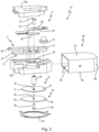
- FIG. 2 shows an exploded view for a specific embodiment of the switch 10 from 1 .
- the switch 10 includes a two-part insulator body 18 having an upper part 18a and a lower part 18b.
- the first external connection 11 is designed as a connection plate 36 which carries the stationary contact part 15 .
- the second external connection 12 is in the form of a connection plate 37 which is electrically connected to the spring part 17 which here has a first leg 38 to which the movable contact part 16 is fixed.
- the spring part 17 also has a second leg 39 which runs parallel to the first leg 38 and has a laterally protruding side wing 41 which comes into contact with the second connecting plate 37 during assembly.
- connection plates 36, 37 and the spring part 17 on top of them are clamped between the upper part 18a and the lower part 18b of the insulator body 18 in such a way that the connection plates 36, 37 are laterally out protruding from the insulator body 18, as seen in the plan view of the assembled switch 10 in Fig 4 can be seen.
- the insulator body 18 is then inserted into an in 2 pushed to recognizable flat housing 42 that has a top 43 and a bottom 44, which are connected to each other via narrow sides 45, wherein the housing has an opening 46 on one of its narrow sides 45 and is plugged with this opening 46 on the insulator body 18, like it in 3 can be seen.
- the bimetal part 19 is designed as a bimetal disk 47 and the spring snap-in part 33 as a spring snap-in disk 48 . Both discs have an edge 51 or 52 and are arranged in a recess 53 which is open to the outside and which is arranged on the lower outer side 18c of the lower part 18b, so that they are supported on peripheral abutments 25a or 25b of the lower part 18 b when the Switch 10 is closed.
- a ring 54 is used, which engages over the edges 51, 52 radially inward and forms the abutment 26 on which the bimetallic disc 47 and the spring snap-action disc 48 are supported with their edges 51 and 52, respectively, when they are the Open switch 10.
- edges 51 and 52 are guided with mechanical play between the abutments 25 and 26, so that the bimetallic disc 47 and the spring snap-in disc 48 can expand when they snap from one geometric configuration to the other.
- the tappet 21 includes the shaft 29 with the lower tapered section 31, on which the bimetallic disc 47 and the spring snap-in disc 48 with their respective through-hole 55 and 56 are plugged with play.
- the plunger 21 passes through the through hole 30 formed in the base 18b.
- the head 27 has a bolt 57 and the head 28 has a bolt 58 .
- the bolt 57 sits in an upper blind hole 61 in the shank 29, the bolt 58 in a lower blind hole 62 in the tapered section 31.
- the heads 27 and 28 are designed to be wider than the bolts 57 and 59 and the shank 29 in diameter.
- the first leg 38 has a through hole 63 with which it is arranged on the bolt 57 with play.
- first leg 38 and the bimetallic disc 47 and the spring snap-in disc 48 are connected to one another under tension and pressure.
- FIG 5 is in a second embodiment a switch 10 ⁇ and in 6 in a third exemplary embodiment, a switch 10" is shown, in each case in a representation as in FIG 1 .
- the same reference numerals denote identical features with identical properties, so that because of the basic structure and the basic function on the above description of the 1 is referenced.
- the switch 10 ⁇ off figure 5 has only the lower head 28, via which the bimetallic part 19 and the spring snap-in part 33 are connected to the plunger 21 in such a way that they move it along the arrow 32 in figure 5 move up and down as the bimetal member 19 and, as a result, the spring snap member 33 snaps from its respective one to the other geometric configuration.
- the spring part 17 bears against the upper end 20a of the plunger 21, so that when the switch 20a is opened it is pushed upwards very quickly by the combined compressive force of the bimetallic part 19 and the spring part 33.
- the bimetal part 19 jumps into its in figure 5 shown configuration back and pulls the plunger 21 down. Because the spring snap-in part 33 is also connected to the plunger 21, during this process it is first pressed down where the plunger 21 engages it, until it also snaps into its in figure 5 other stable geometric configuration shown.
- the spring member 17 is not actively pulled down by the plunger 17 because the head 27 from 1 is not provided here. Nevertheless, the switch 10' closes faster than a switch without forced coupling between the plunger 21 and the bimetal part 19 and the spring snap part 33, because the plunger 21 is moved downwards so quickly that it does not offer any resistance to the closing movement of the spring part 17.
- both the opening speed and the closing speed are therefore increased compared to a switch in which only one bimetal part 19 is provided, which is also not positively coupled to the plunger 21.
- the insulator body 18 When assembling, the insulator body 18 is first joined together so that the two connection plates 36, 37 and the spring part 17 are clamped between the upper part 18a and the lower part 18b.
- the plunger 21 is then captively connected to the bimetal part 19 and the spring snap part 33 via the head 28, and this unit thereafter in 2 inserted from below into the preassembled insulator body 18, ie into the depression 53 in the lower part 18b.
- the plunger is passed with its upper end 20a through the through-hole 30 and comes into contact with the first leg 38 with its upper end 20a.
- switch 10" At the switch 10" off 6 the lower head 28 is also dispensed with.
- switch 10" has bimetal part 19 below spring snap-in part 33.
- both heads 27, 28 are missing, there is no risk here either of the ram 21 tilting or jamming because it is guided in the through-hole 30.
- the bimetal part 19 If the temperature of the bimetal part 19 increases beyond its transition temperature, the bimetal part 19 jumps from the in 6 shown low-temperature configuration into its other geometric configuration. In doing so, it presses in the middle of the spring snap-in part 33, which is thereby gradually bent up in its center until it suddenly snaps into its other geometrically stable configuration and, together with the bimetallic part 19, pushes the plunger into 6 suddenly pushed upwards.
- the spring part 17 rests against the upper end 20a of the plunger 21, so that when the switch 20a is opened it is also pushed up very quickly here by the combined compressive force of the bimetal part 19 and the spring part 33.
- the spring part 17 is not actively pulled down by the plunger 17 because the head 27 is off 1 not provided here either. Nevertheless opens the switch 10 ⁇ is not only quicker than a switch without a spring snap-in part 33, it can also close quicker if designed accordingly. This faster closing is due to the fact that the bimetallic part 19 is moved downwards so quickly as a result of the spring snap-in part 33 snapping over that it no longer offers any resistance to the plunger 21 when the plunger 21 is pushed all the way down again into its in 6 shown position is moved.
- the insulator body 18 is assembled so that the two connecting plates 36, 37 and the spring part 17 are clamped between the upper part 18a and the lower part 18b.
- the plunger 21 is then passed through the through hole 30 with its upper end 20a and comes into contact with the first leg 38 with its upper end 20a.
Description
Die vorliegende Erfindung betrifft einen temperaturabhängigen Schalter mit einem ersten und einem zweiten Außenanschluss, wobei der erste und zweite Außenanschluss an einem Isolatorkörper festgelegt sind, der erste und der zweite Außenanschluss als erstes bzw. zweites Anschlussblech ausgebildet sind, die beiden Anschlussbleche aus dem Isolatorkörper herausragen, und der Isolatorkörper in einem Gehäuse angeordnet ist, mit einem mit dem ersten Außenanschluss elektrisch leitend verbundenen stationären Kontaktteil, einem mit dem stationären Kontaktteil zusammenwirkenden beweglichen Kontaktteil, das an einem Federteil befestigt ist, das elektrisch leitend mit dem zweiten Außenanschluss verbunden ist, und das das bewegliche Kontaktteil gegen das stationäre Kontaktteil drückt, einem Bimetallteil und einem zwischen dem Bimetallteil und dem Federteil angeordneten Stößel, wobei das Bimetallteil bei Überschreiten einer Schalttemperatur über den Stößel Druckkräfte auf das Federteil ausübt und dadurch das bewegliche Kontaktteil von dem stationären Kontaktteil abhebt, und wobei das Federteil einen ersten und einen zweiten Schenkel aufweist, das bewegliche Kontaktteil an dem ersten Schenkel befestigt ist, der zweite Schenkel elektrisch mit dem zweiten Anschlussblech verbunden ist, und der Stößel zwischen dem ersten Schenkel und dem Bimetallteil angeordnet ist.The present invention relates to a temperature-dependent switch with a first and a second external connection, the first and second external connection being fixed to an insulator body, the first and second external connection being designed as a first or second connection plate, the two connection plates protruding from the insulator body, and the insulator body is arranged in a housing, having a stationary contact part which is electrically conductively connected to the first external connection, a movable contact part which cooperates with the stationary contact part and is fastened to a spring part which is electrically conductively connected to the second external connection, and which the movable contact part presses against the stationary contact part, a bimetallic part and a plunger arranged between the bimetallic part and the spring part, the bimetallic part exerting compressive forces on the spring part via the plunger when a switching temperature is exceeded and dadu rch the movable contact part lifts off the stationary contact part, and wherein the spring part has a first and a second leg, the movable contact part is fixed to the first leg, the second leg is electrically connected to the second terminal plate, and the plunger between the first leg and the bimetal part is arranged.
Ein derartiger Schalter ist aus der
Der bekannte Schalter ist Temperaturschutzschalter, bei dem durch die Schaltbewegung einer Bimetallscheibe über einen Stößel Druckkräfte auf ein stromführendes Federteil übertragen werden, das hier als Schließfeder wirkt. Die Schließfeder trägt ein bewegliches Kontaktteil, das sie bei geschlossenem Schalter gegen ein stationäres Kontaktteil drückt. Stationäres Kontaktteil und Schließfeder sind jeweils mit einem Anschlussblech verbunden. Die beiden Anschlussbleche sind an einem Isolatorkörper festgelegt, aus dem sie seitlich herausragen. Der Temperaturschutzschalter weist ein flaches Gehäuse auf, aus dem die beiden Anschlussbleche als Außenanschlüsse herausragen.The well-known switch is a temperature protection switch, in which the switching movement of a bimetallic disc transmits compressive forces via a plunger to a current-carrying spring part, which acts as a closing spring here. The closing spring carries a movable contact part which presses it against a stationary contact part when the switch is closed. The stationary contact part and closing spring are each connected to a connecting plate. The two connecting plates are fixed to an insulator body, from which they protrude laterally. The temperature protection switch has a flat housing from which the two connection plates protrude as external connections.
Derartige temperaturabhängige Schalter werden in bekannter Weise dazu verwendet, elektrische Geräte vor Überhitzung zu schützen. Dazu wird der Schalter über seine beiden Außenanschlüsse elektrisch mit dem zu schützenden Gerät in Reihe geschaltet und mechanisch so an dem Gerät angeordnet, dass er mit diesem in thermischer Verbindung steht.Such temperature-dependent switches are used in a known manner to protect electrical devices from overheating. For this purpose, the switch is electrically connected in series with the device to be protected via its two external connections and is mechanically arranged on the device in such a way that it is thermally connected to it.
In der Ausführung eines Schalters gemäß der
Der Betriebsstrom des zu schützenden Gerätes fließt so durch die beiden Kontaktteile und die Federschnappscheibe in das Unterteil.The operating current of the device to be protected flows through the two contact parts and the spring snap-in disc into the lower part.
Der aus der
Unterhalb der Ansprechtemperatur der Bimetall-Schnappscheibe ist der Stromkreis geschlossen und das zu schützende Gerät wird über den Schalter mit Strom versorgt. Erhöht sich die Temperatur entweder infolge eines zu hohen Betriebsstromes oder infolge eines zu sehr aufgeheizten, zu schützenden Gerätes über einen zulässigen Wert hinaus, so verformt sich die Bimetall-Schnappscheibe, wodurch die Federschnappscheibe von ihrer ersten stabilen geometrischen Konfiguration, in der sie das bewegliche Kontaktteil gegen das stationäre Kontaktteil drückt, in ihre zweite stabile geometrische Konfiguration umspringt, in der sie das bewegliche Kontaktteil von dem stationären Kontaktteil abhebt. Der Schalter wird geöffnet und die Versorgung des zu schützenden Gerätes wird unterbrochen.Below the response temperature of the bimetallic snap-action disc, the circuit is closed and the device to be protected is supplied with power via the switch. If the temperature rises above a permissible value, either as a result of an excessively high operating current or as a result of the device to be protected being overheated, the bimetal snap-action disc deforms, causing the spring snap-action disc to move from its first stable geometric configuration in which it holds the moving contact part presses against the stationary contact part, jumps into its second stable geometric configuration, in which it lifts the movable contact part from the stationary contact part. The switch is opened and the power supply to the device to be protected is interrupted.
Das jetzt stromlose Gerät kann sich dann wieder abkühlen. Dabei kühlt sich auch der thermisch an das Gerät angekoppelte Schalter wieder ab, der daraufhin selbsttätig wieder schließt. Während ein derartiges Schaltverhalten zum Schutz z.B. eines Haartrockners durchaus sinnvoll sein kann, ist dies überall dort nicht erwünscht, wo sich das zu schützende Gerät nach dem Abschalten nicht automatisch wieder einschalten darf, um Beschädigungen zu vermeiden. Dies gilt z.B. für Elektromotoren, die als Antriebsaggregate eingesetzt werden.The now de-energized device can then cool down again. The switch that is thermally coupled to the device also cools down again and then closes again automatically. While such a switching behavior can make sense to protect e.g. a hair dryer, this is not desirable wherever the device to be protected must not be switched on again automatically after it has been switched off in order to avoid damage. This applies, for example, to electric motors that are used as drive units.
Bei bekannten temperaturabhängigen Schaltern wird deshalb häufig ein sogenannter Selbsthaltewiderstand vorgesehen, der elektrisch parallel zu den Anschlüssen liegt, wie dies ebenfalls in der
Abweichend von der Ausführung des Schalters gemäß der
Das Schaltwerk kann auch eine Bimetall-Federzunge umfassen, wie es in der
Wenn der temperaturabhängige Schalter besonders hohe Ströme führen soll, so wird häufig ein Stromübertragungsglied in Form einer Kontaktbrücke oder eines Kontakttellers eingesetzt, das von einem Federteil bewegt wird und zwei Kontaktteile trägt, die mit zwei stationären Gegenkontakten zusammenwirken; siehe beispielsweise die
Auf diese Weise fließt der Betriebsstrom des zu schützenden Gerätes von dem ersten Gegenkontakt über das erste Kontaktteil in den Kontaktteller, durch diesen hindurch zum zweiten Kontaktteil und von diesem in den zweiten Gegenkontakt. Das Federteil ist somit stromlos. Es ist auch bekannt, das Federteil selbst, also beispielsweise eine Bimetall-Schnappscheibe oder eine gegen ein Bimetallteil arbeitende Federschnappscheibe als Kontaktbrücke zu verwenden, die den Betriebsstrom führt.In this way, the operating current of the device to be protected flows from the first mating contact via the first contact part into the contact plate, through this to the second contact part and from there into the second mating contact. The spring part is thus de-energized. It is also known to use the spring part itself, for example a bimetal snap-action disc or a spring snap-action disc working against a bimetal part, as a contact bridge which carries the operating current.
Die bekannten Schalter müssen dazu in der Lage sein, Motoren sowohl im Grenzbetrieb bei maximal zulässiger Leistung als auch bei blockierendem Rotor zuverlässig zu schützen. Um zu prüfen, ob der Schalter dies auch leistet, werden üblicher Weise zwei Tests durchgeführt.The known switches must be able to reliably protect motors both in limit operation at maximum permissible power and when the rotor is locked. Two tests are usually carried out to check whether the switch is capable of doing this.
Bei dem sogennanten Heating Test wird der Motor mit maximaler Leistung betrieben, wobei weder der Stromfluss durch den Schalter noch die dabei von dem Motor auf den Schalter übertragene Hitze den Schalter öffnen darf.In the so-called heating test, the motor is operated at maximum power, with neither the current flow through the switch nor the heat transferred from the motor to the switch being allowed to open the switch.
Bei dem sogenannten Locked Rotor Test dagegen wird der Motor bei blockiertem Rotor mit der Betriebsspannung verbunden, was dazu führt, dass ein Betriebsstrom durch den Motor fließt, der drei bis fünf Mal größer ist als der übliche Betriebsstrom.In the so-called locked rotor test, on the other hand, the motor is connected to the operating voltage when the rotor is locked, which means that an operating current flows through the motor that is three to five times higher than the usual operating current.
Dieser hohe Strom führt natürlich auch zu einem Aufheizen des Motors und damit zu einer Temperaturerhöhung an dem Schalter. Um den Motor vor Überhitzung zu schützen, muss für eine gute thermische Ankopplung des Schalters an den Motor gesorgt werden.Of course, this high current also leads to heating of the motor and thus to an increase in temperature at the switch. In order to protect the motor from overheating, a good thermal connection between the switch and the motor must be ensured.
Neben der guten thermischen Ankopplung muss der Schalter auch die erforderliche Zahl von Schaltzyklen erfüllen, die bei typischen Anforderungen, wie sie oben beschrieben wurden, mindestens bei 3.000 liegen sollten.In addition to good thermal coupling, the switch must also meet the required number of switching cycles, which should be at least 3,000 for typical requirements as described above.
Damit der Schalter hohe Betriebsströme führen kann, ohne dass dadurch die Bimetallscheibe bereits auf ihre Schalttemperatur aufgeheizt wird, schlägt die gattungsbildende
Die Bimetallscheibe wird zudem in einer Vertiefung an einer Außenseite des Isolatorkörpers angeordnet, um sie thermisch einerseits von der stromführenden Schließfeder zu entkoppeln und anderseits eine gute thermische Ankopplung der Bimetallscheibe an das zu schützende Gerät zu ermöglichen.The bimetallic disc is also arranged in a recess on an outside of the insulator body in order to thermally decouple it from the current-carrying closing spring on the one hand and to enable good thermal coupling of the bimetallic disc to the device to be protected on the other.
Das in dem bekannten Schalter verwendete temperaturabhängige Schaltwerk ist prinzipiell so aufgebaut, wie ein sogenannter Thermostatschalter, der zur Regelung der Temperatur eines damit ausgestatteten Gerätes verwendet wird, beispielsweise zur Regelung der Temperatur eine Heizplatte. Beispiele derartiger Thermostatschalter finden sich in folgenden Schutzrechten:
Der aus der gattungsbildenden
Bei dem Schalter gemäß der
Versuche in den Räumen der Anmelderin haben gezeigt, dass der bekannte Schalter bei einem durch die Schließfeder fließenden Strom von 35 A im locked rotor test mit 120 VAC oft schon nach 300 Schaltzyklen nicht mehr öffnet, weil die Kontaktteile durch Lichtbogenbildung miteinander verschweißt wurden.Tests on the applicant's premises have shown that the known switch often no longer opens after 300 switching cycles with a current of 35 A flowing through the closing spring in the locked rotor test with 120 VAC because the contact parts were welded together by arcing.
Die
Unterhalb ihrer Schalttemperatur drückt die Bimetall-Schnappscheibe den Bolzen in Richtung von zwei stationären Gegenkontakten, an die sich die Kontaktbrücke unter der Kraft der Druckfeder anlegt, die sich anderen Endes an der Bimetall-Schnappscheibe abstützt.Below its switching temperature, the bimetallic snap-action disc presses the bolt in the direction of two stationary mating contacts, against which the contact bridge rests under the force of the compression spring, which is supported on the bimetallic snap-action disc at the other end.
Erhöht sich die Temperatur der Bimetall-Schnappscheibe, so zieht diese den Bolzen von den beiden stationären Gegenkontakten weg, wobei der Bolzen dabei die Kontaktbrücke von den Gegenkontakten abhebt, so dass der Schalter geöffnet wird.If the temperature of the bimetallic snap-action disc increases, it pulls the bolt away from the two stationary mating contacts, the bolt lifting the contact bridge from the mating contacts so that the switch opens.
Die
Auf der von dem Stößel abgelegenen Seite der Feder-Schnappscheibe ist eine Bimetall-Schnappscheibe angeordnet, die unterhalb ihrer Schalttemperatur lose unterhalb der Feder-Schnappscheibe liegt, so dass der Schalter geschlossen ist.On the side of the spring snap-action disk remote from the plunger, a bimetallic snap-action disk is arranged, which lies loosely below the spring snap-action disk below its switching temperature, so that the switch is closed.
Erhöht sich die Temperatur der Bimetall-Schnappscheibe, so drückt diese gegen den Stößel und die Feder-Schnappscheibe, so dass sich die Kontaktbrücke von den stationären Gegenkontakten abhebt und die Feder-Schnappscheibe von ihrer ersten in ihre zweite mechanisch stabile Lage umschnappt. In diesem geöffneten Zustand drücken sowohl die Feder-Schnappscheibe als auch die Bimetall-Schnappscheibe die Kontaktbrücke von den stationären Gegenkontakten weg.If the temperature of the bimetallic snap-action disc increases, it presses against the plunger and the spring snap-action disc so that the contact bridge lifts off the stationary mating contacts and the spring snap-action disc snaps from its first to its second mechanically stable position. In this open condition, both the spring-loaded snap disk and the bi-metal snap-action disk push the contact bridge away from the stationary mating contacts.
Oberhalb der Kontaktbrücke ist ein Schaltstempel vorgesehen, der über eine zweite bistabile Feder-Schnappscheibe an einem Betätigungsknopf angeordnet ist. Wenn der Betätigungsknopf in das Gehäuse des Schalters hineingedrückt wird, so drückt der Schaltstempel bei geöffnetem Schalter gegen die Kontaktbrücke. Die Stellkraft der zweiten Feder-Schnappscheibe ist geringer als die Summe der Stellkräfte der ersten Feder-Schnappscheibe und der Bimetall-Schnappscheibe, so dass beim Eindrücken des Betätigungsknopfes in das Gehäuse die zweite Feder-Schnappscheibe in ihre inaktive Position umschnappt, wenn sich die Bimetall-Schnappscheibe oberhalb ihrer Schalttemperatur befindet.A switching plunger is provided above the contact bridge and is arranged on an actuating button via a second bistable spring snap-action disk. When the actuating button is pressed into the housing of the switch, the switching plunger presses against the contact bridge when the switch is open. The actuating force of the second spring snap-action disc is less than the sum of the actuating forces of the first spring snap-action disc and the bimetal snap-action disc, so that when the actuating button is pressed into the housing, the second spring snap-action disc snaps into its inactive position when the bimetal Snap disk is above its switching temperature.
Sinkt die Temperatur der Bimetall-Schnappscheibe wieder, so springt diese in ihre unbelastete Stellung zurück, die Kontaktbrücke wird jedoch durch die erste Feder-Schnappscheibe in geöffneter Stellung gehalten. Ein erneutes Drücken auf den Betätigungsknopf bewirkt jetzt, dass der Schaltstempel die Kontaktbrücke nach unten drückt, so dass die erste Feder-Schnappscheibe wieder in ihre erste stabile Position umspringt, in der der Schalter geschlossen ist. Die Stellkraft der zweiten Feder-Schnappscheibe muss dazu größer sein als die der ersten Feder-Schnappscheibe.If the temperature of the bimetallic snap-action disc drops again, it springs back into its unloaded position, but the contact bridge is held in the open position by the first spring snap-action disc. Pressing the actuating button again now causes the switching plunger to press the contact bridge downwards, so that the first spring snap-action disc snaps back into its first stable position, in which the switch is closed. The actuating force of the second spring snap-action disc must be greater than that of the first spring snap-action disc.
Aus der
Die Bimetall-Schnappscheibe ist über eine Federscheibe auf einer Schulter des Gehäuses des temperaturabhängigen Schalters festgelegt. Die Federscheibe ermöglicht ein Umschnappen der Bimetall-Schnappscheibe und dämpft die Bewegung der Bimetall-Schnappscheibe während der Umschaltvorgänge und soll den Wärmeaustausch zwischen der Bimetall-Schnappscheibe und dem Gehäuse verbessern.The bimetallic snap disk is secured by a spring washer on a shoulder of the temperature sensitive switch housing. The spring washer enables the bimetal snap-action disc to snap over and dampens the movement of the bimetal snap-action disc during switching processes and is intended to improve the heat exchange between the bimetal snap-action disc and the housing.
Aus der
Aus dem
Aus der
Aus dem
Ausgehend von diesem Stand der Technik ist es Aufgabe der vorliegenden Erfindung, den eingangs genannten Schalter derart weiterzubilden, dass er bei einfachem und preiswertem Aufbau auch bei höheren Schaltströmen noch eine ausreichende Anzahl von Schaltzyklen bereitstellt.Proceeding from this prior art, it is the object of the present invention to further develop the switch mentioned at the outset in such a way that, with a simple and inexpensive construction, it still provides a sufficient number of switching cycles even with higher switching currents.
Erfindungsgemäß wird diese Aufgabe bei dem eingangs genannten Schalter dadurch gelöst, dass der Stößel so zwischen dem Federteil und dem Bimetallteil angeordnet ist, dass er Druck- und Zugkräfte von dem Bimetallteil auf das Federteil überträgt.According to the invention, this object is achieved with the switch mentioned at the outset in that the tappet is arranged between the spring part and the bimetallic part in such a way that it transmits compressive and tensile forces from the bimetallic part to the spring part.
Weil der Stößel jetzt im Gegensatz zu dem bekannten Schalter nicht nur beim Öffnen des Schalters sondern auch beim Schließen des Schalters die Bewegung des Bimetallteils auf das Federteil überträgt, wird die Schließgeschwindigkeit erhöht, die erfindungsgemäß nicht mehr nur durch das Federteil, also die Schließfeder bestimmt wird.Because the plunger, in contrast to the known switch, now transmits the movement of the bimetal part to the spring part not only when the switch is opened but also when the switch is closed, the closing speed is increased, which according to the invention is no longer determined only by the spring part, i.e. the closing spring .
Die Erfinder der vorliegenden Anmeldung sind nicht den sich anbietenden Weg gegangen, die Lichtbogenausbildung selbst zu beeinflussen oder das Federteil umzugestalten, sondern haben die Schaltdynamik des bekannten Schalters dadurch erhöht, dass zwischen der Schließfeder und dem Bimetallteil eine Zwangskopplung bereitgestellt wird.The inventors of the present application did not take the suggested route of influencing the formation of the arc itself or redesigning the spring part, but instead increased the switching dynamics of the known switch by providing a forced coupling between the closing spring and the bimetallic part.
Diese Zwangskopplung wird auf konstruktiv einfache und preiswerte Weise dadurch erreicht, dass der Stößel nicht nur beim Öffnen in bekannter Weise eine Druckkraft von dem Bimetallteil auf das Federteil überträgt, sondern erfindungsgemäß beim Schließen eine Zugkraft von dem Bimetallteil auf das Federteil überträgt.This forced coupling is achieved in a structurally simple and inexpensive manner in that the plunger not only transmits a compressive force from the bimetal part to the spring part when opening in a known manner, but also transmits a tensile force from the bimetal part to the spring part when closing.
Diese Maßnahme erhöht die Schließgeschwindigkeit des Schalters, was insbesondere bei hohen geschalteten Strömen wider Erwarten den Kontaktverschleiß bereits deutlich verringert, wodurch nach Erkenntnis des Erfinder der vorliegenden Anmeldung bereits die Lebensdauer, also die Zahl der Schaltzyklen deutlich erhöht.This measure increases the closing speed of the switch, which, contrary to expectations, already significantly reduces contact wear, especially when switching high currents, which, according to the inventor of the present application, already significantly increases the service life, ie the number of switching cycles.
Von Vorteil ist dabei insbesondere, dass nicht die Stellkraft des Federteils erhöht wird, sondern durch die Bimetallscheibe eine zusätzliche Schließkraft aufgebracht wird. Auf diese Weise wird die Öffnungsgeschwindigkeit des Schalters nicht negativ beeinflusst, denn beim Öffnen muss die Bimetallscheibe lediglich nach wie vor die bisherige Schließkraft des Federteils überwinden.It is particularly advantageous that the actuating force of the spring part is not increased, but rather an additional closing force is applied by the bimetallic disc. In this way, the opening speed of the switch is not negatively influenced, because when opening, the bimetallic disc only has to overcome the previous closing force of the spring part.
Die der Erfindung zugrundeliegende Aufgabe wird auf diese Weise vollkommen gelöst.The object on which the invention is based is completely solved in this way.
Dabei ist es bevorzugt, wenn der Schalter ein über den Stößel auf das Federteil Druck- und Zugkräfte übertragendes Federschnappteil umfasst.In this case, it is preferred if the switch comprises a spring snap-in part that transmits compressive and tensile forces to the spring part via the plunger.
Hier ist von Vorteil, dass durch das zusätzliche Federschnappteil nicht nur die Schließgeschwindigkeit weiter erhöht wird, sondern auch die Öffnungsgeschwindigkeit erhöht wird. Beim Öffnen drückt zunächst das Bimetallteil gegen das Federschnappteil, bis dieses schlagartig in seine andere Konfiguration umschnappt und zusammen mit der Stellkraft des Bimetallteils gegen die Schließkraft des Federteils arbeitet und den Schalter schnell öffnet.The advantage here is that the additional spring snap part not only further increases the closing speed, but also increases the opening speed. When opening, the bimetal part first presses against the spring snap part until it suddenly snaps into its other configuration and works together with the actuating force of the bimetal part against the closing force of the spring part and opens the switch quickly.
Diese Maßnahme ist insofern ungewöhnlich, als der bekannte Schalter ja bereits ein Federteil aufweist, das in bekannter Weise gegen die Kraft des Bimetallteils arbeitet. Erfindungsgemäß wird jetzt zusätzlich ein Federschnappteil vorgesehen, um die Dynamik des Schaltvorganges weiter zu erhöhen.This measure is unusual in that the known switch already has a spring part which, in a known manner, counteracts the force of the bimetallic part is working. According to the invention, a spring snap part is now additionally provided in order to further increase the dynamics of the switching process.
Dies führt dazu, dass der neue Schalter auch bei hohen Schaltströmen die erforderliche Anzahl an Schaltzyklen übersteht.As a result, the new switch withstands the required number of switching cycles even with high switching currents.
Unter einem "Federschnappteil" wird im Rahmen der vorliegenden Erfindung ein Federteil verstanden, das zwei stabile geometrische Konfigurationen aufweist, wie dies für Federschnappscheiben bei temperaturabhängigen Schaltern allgemein bekannt ist. Durch das Bimetallteil wird das Federschnappteil von seiner einen in Richtung auf die andere geometrisch stabile Konfiguration gedrückt, bis das Federschnappteil dann schlagartig vollständig umspringt.In the context of the present invention, a “spring snap-in part” is understood to be a spring part that has two stable geometric configurations, as is generally known for spring snap-in disks in temperature-dependent switches. The spring snap part is pushed by the bimetallic part from one of its geometrically stable configurations in the direction of the other until the spring snap part suddenly snaps over completely.
Der Schalter kann jeweils mit einem Heizwiderstand für definiertes stromabhängiges Schalten und ggf. zusätzlich mit einem Selbsthaltewiderstand versehen sein, damit der geöffnete Schalter nicht abkühlt und selbsttätig wieder schließt.The switch can each be provided with a heating resistor for defined current-dependent switching and optionally also with a self-holding resistor so that the open switch does not cool down and closes again automatically.
Dabei ist es bevorzugt, wenn das Federschnappteil und das Bimetallteil an einem ersten Ende des Stößels und das Federteil an einem zweiten Ende des Stößel angeordnet sind, wobei vorzugsweise der Stößel einen Schaft aufweist, der an seinem ersten Ende einen verjüngten Abschnitt aufweist, der einen gegenüber dem verjüngten Abschnitt verbreiterten Kopf trägt, wobei auf dem verjüngten Abschnitt das Bimetallteil und ggf. das Federschnappteil mit ihrem jeweiligen Durchgangsloch derart angeordnet sind, dass das Bimetallteil und das ggf. vorgesehene Federschnappteil mit Spiel zwischen dem Kopf und dem Schaft gehalten werden, und weiter vorzugsweise der Stößel einen Schaft aufweist, der an seinem zweiten Ende einen verjüngten Abschnitt aufweist, der einen gegenüber dem verjüngten Abschnitt verbreiterten Kopf trägt, wobei auf dem verjüngten Abschnitt das Federteil mit einem Durchgangsloch derart angeordnet ist, dass das Federteil mit Spiel zwischen dem Kopf und dem Schaft gehalten wird.It is preferred if the spring snap part and the bimetallic part are arranged at a first end of the plunger and the spring part at a second end of the plunger, the plunger preferably having a shank which has a tapered section at its first end, the opposite the tapered section carries a head that is widened, the bimetal part and optionally the spring snap-in part with their respective through hole being arranged on the tapered section in such a way that the bimetal part and the optionally provided spring snap-in part are held with play between the head and the shaft, and more preferably the tappet has a shank which has a tapered portion at its second end, which carries a head which is widened relative to the tapered portion, the spring part having a through hole being arranged on the tapered portion in such a way that the spring part has play between the head and the shaft is held.
Diese Maßnahmen sind konstruktiv von Vorteil. Sie sorgen auf einfache Weise dafür, dass Federteil, Bimetallteil und Federschnappteil so an dem Stößel befestigt sind, dass zwischen ihnen Zug- und Druckkräfte übertragen werden können.These measures are constructively advantageous. They ensure in a simple way that the spring part, bimetal part and spring snap-in part are fastened to the plunger in such a way that tensile and compressive forces can be transmitted between them.
Der verjüngte Abschnitt kann mit dem Kopf oder dem Schaft einstückig ausgebildet sein, wobei entweder der verjüngte Abschnitt in ein in dem Schacht vorgesehenes Sackloch eingesetzt wird oder der Kopf auf den verjüngten Abschnitt aufgesetzt wird. Der Kopf kann auch als Niet ausgebildet sein, dessen Bolzen in ein in dem verjüngten Abschnitt vorgesehenes Sackloch eingesetzt wird.The tapered portion may be integrally formed with the head or the shank, either by inserting the tapered portion into a blind hole provided in the well, or by fitting the head over the tapered portion. The head can also be designed as a rivet, the bolt of which is inserted into a blind hole provided in the tapered section.
Weiter ist es bevorzugt, wenn das Bimetallteil als längliche Zunge ausgebildet ist, die an ihren gegenüberliegenden Schmalseiten jeweils zwischen zwei Widerlagern angeordnet ist, die sich in Längsrichtung des Stößels gegenüberliegen, weiter vorzugsweise das Federschnappteil als längliche Zunge ausgebildet ist, die an ihren gegenüberliegenden Schmalseiten jeweils zwischen zwei Widerlagern angeordnet ist, die sich in Längsrichtung des Stößels gegenüberliegen, weiter vorzugsweise das Bimetallteil als Bimetall-Scheibe ausgebildet ist, die an ihren Rand zwischen zwei Widerlagern angeordnet ist, die sich in Längsrichtung des Stößels gegenüberliegen, weiter vorzugsweise das Federschnappteil als Feder-Schnappscheibe ausgebildet ist, die an ihren Rand zwischen zwei Widerlagern angeordnet ist, die sich in Längsrichtung des Stößels gegenüberliegen.It is also preferred if the bimetal part is designed as an elongated tongue which is arranged on its opposite narrow sides between two abutments which are opposite one another in the longitudinal direction of the plunger, more preferably the spring snap-in part is designed as an elongated tongue which is arranged on its opposite narrow sides in each case is arranged between two abutments which are opposite one another in the longitudinal direction of the plunger, more preferably the bimetal part is designed as a bimetal disc which is arranged at its edge between two abutments which are opposite one another in the longitudinal direction of the plunger, more preferably the spring snap-in part is a spring Snap disk is formed, which is arranged at its edge between two abutments, which are opposite in the longitudinal direction of the plunger.
Diese Maßnahmen betreffen die möglichen Ausgestaltungen von Federschnappteil und Bimetallteil als längliche Zunge oder Scheibe. Wobei unter einer "Scheibe" im Rahmen der vorliegenden Erfindung ein allgemein rundes, kreisrundes, ovales oder abgerundetes Teil verstanden wird.These measures relate to the possible configurations of the spring snap-in part and the bimetallic part as an elongated tongue or disc. In the context of the present invention, a “disk” is understood to mean a generally round, circular, oval or rounded part.
Dabei ist es bevorzugt, wenn das Gehäuse eine Oberseite und eine Unterseite aufweist, die über Schmalseiten miteinander verbunden sind, und das Gehäuse an einer seiner Schmalseiten eine Öffnung aufweist und mit dieser Öffnung auf den Isolatorkörper gesteckt ist, weiter vorzugsweise die beiden Schenkel zum Unterbrechen einer leitenden Verbindung zwischen den beiden Anschlussblechen von dem Stößel auseinandergebogen werden, weiter vorzugsweise der zweite Schenkel an dem zweiten Anschlussblech anliegt, weiter vorzugsweise der Isolatorkörper aus zwei Teilkörpern zusammengesetzt ist, und die beiden Anschlussbleche zwischen den beiden Teilkörpern liegen.It is preferred if the housing has an upper side and an underside that are connected to one another via narrow sides, and the housing has an opening on one of its narrow sides and is plugged onto the insulator body with this opening, more preferably the two legs for interrupting a conductive connection between the two connection plates of the ram are bent apart, more preferably the second leg rests against the second connection plate, more preferably the insulator body is composed of two part-bodies, and the two connection plates lie between the two part-bodies.
Ferner ist es bevorzugt, wenn das Bimetallteil in einer Vertiefung an einer Außenseite des Isolatorkörpers angeordnet ist, weiter vorzugsweise das Federschnappteil in einer Vertiefung an einer Außenseite des Isolatorkörpers angeordnet ist, und schließlich in der Vertiefung ein von außen eingesetzter Ring vorgesehen ist, der als Widerlager für das Federschnappteil und/oder das Bimetallteil dientFurthermore, it is preferred if the bimetal part is arranged in a depression on an outside of the insulator body, more preferably the spring snap-in part is arranged in a depression on an outside of the insulator body, and finally a ring inserted from the outside is provided in the depression, which acts as an abutment is used for the spring snap part and/or the bimetallic part
Diese Maßnahmen sind konstruktiv von Vorteil, sie führen zu einem kompakten preiswerten Schalter.These measures are structurally advantageous, they lead to a compact, inexpensive switch.
Vor diesem Hintergrund betrifft die vorliegende Erfindung auch einen Schalter der eingangs genannten Art, der ein Federschnappteil aufweist, das zumindest bei Überschreiten der Schalttemperatur den Stößel gegen das Federteil drückt.Against this background, the present invention also relates to a switch of the type mentioned at the outset, which has a spring snap-in part that presses the plunger against the spring part at least when the switching temperature is exceeded.
Vorzugsweise sind das Federschnappteil und das Bimetallteil an einem ersten Ende des Stößels und das Federteil an einem zweiten Ende des Stößel angeordnet, wobei weiter vorzugsweise das Federschnappteil und das Bimetallteil so mit dem Stößel verbunden sind, dass sie auf den Stößel Druck- und Zugkräfte übertragen, weiter vorzugsweise weist der Stößel einen Schaft auf, der an seinem ersten Ende einen verjüngten Abschnitt aufweist, der einen gegenüber dem verjüngten Abschnitt verbreiterten Kopf trägt, wobei auf dem verjüngten Abschnitt das Bimetallteil und das Federschnappteil mit ihrem jeweiligen Durchgangsloch derart angeordnet sind, dass das Bimetallteil und das Federschnappteil mit Spiel zwischen dem Kopf und dem Schaft gehalten werden.The spring snap-in part and the bimetallic part are preferably arranged at a first end of the plunger and the spring part is arranged at a second end of the plunger, with the spring snap-in part and the bimetallic part preferably being connected to the plunger in such a way that they transmit compressive and tensile forces to the plunger, More preferably, the plunger has a shaft which has a tapered section at its first end, which carries a head that is widened compared to the tapered section, the bimetal part and the spring snap-in part with their respective through hole being arranged on the tapered section in such a way that the bimetal part and the spring catch are held with play between the head and the shaft.
Diese Maßnahmen führen wie die oben diskutierte, beidseitige Zwangskopplung des Stößels auch noch zu einer verbesserten Schaltdynamik, so dass die Anzahl der Schaltzyklen erhöht wird.Like the forced coupling of the tappet on both sides discussed above, these measures also lead to improved switching dynamics, so that the number of switching cycles is increased.
Dabei ist es bevorzugt, wenn das Bimetallteil zwischen dem Stößel und dem Federschnappteil angeordnet ist.In this case, it is preferred if the bimetal part is arranged between the plunger and the spring snap-in part.
Hier ist von Vorteil, dass das Federschnappteil außen an dem Bimetallteil liegt und dieses schützt.The advantage here is that the spring snap part is on the outside of the bimetal part and protects it.
Alternativ ist es bevorzugt, wenn das Federschnappteil zwischen dem Stößel und dem Bimetallteil angeordnet ist.Alternatively, it is preferred if the spring snap part is arranged between the plunger and the bimetallic part.
Hier ist zum einen von Vorteil, dass das außen liegende Bimetallteil thermisch gut an ein zu schützendes Gerät angekoppelt werden kann, wobei ferner von Vorteil ist, dass auch ohne Zwangskopplung zwischen Stößel und Bimetallteil sowie Federschnappteil das Bimetallteil das in Richtung Stößel über ihm liegende Federschnappteil beim Öffnen des Schalters sehr schnell zum Umschnappen bringt.On the one hand, it is advantageous here that the external bimetallic part can be thermally well coupled to a device to be protected, it being also advantageous that even without forced coupling between the plunger and the bimetallic part as well as the spring snap-in part, the bimetallic part can retain the spring snap-in part lying above it in the direction of the plunger Opening the switch causes it to snap very quickly.
Weitere Vorteile ergeben sich aus der Beschreibung und der beigefügten Zeichnung.Further advantages result from the description and the attached drawing.
Ausführungsbeispiele der Erfindung sind in der beigefügten Zeichnung dargestellt und werden in der nachfolgenden Beschreibung näher erläutert. Es zeigen:
- Fig. 1
- einen schematischen, nicht maßstabsgetreuen Längsschnitt durch ein erstes Ausführungsbeispiel eines temperaturabhängigen Schalters, bei dem in einem Schaltwerk ein bewegliches Kontaktteil mit einem stationären Kontaktteil zusammenwirkt, und bei dem zwischen einem Bimetallteil und einem Federteil ein Stößel angeordnet ist;
- Fig. 2
- in einer schematischen Explosionsdarstellung einen Schalter, der das Schaltwerk aus
Fig. 1 verwendet; - Fig. 3
- den zusammengebauten Schalter aus
Fig. 2 in einem Längsschnitt; - Fig. 4
- den Schalter aus
Fig. 3 in Draufsicht, jedoch ohne Gehäuse; - Fig. 5
- in einer Darstellung wie
Fig. 1 ein zweites Ausführungsbeispiel für den temperaturabhängigen Schalter; und - Fig. 6
- in einer Darstellung wie
Fig. 1 ein drittes Ausführungsbeispiel für den temperaturabhängigen Schalter.
- 1
- a schematic longitudinal section, not true to scale, through a first exemplary embodiment of a temperature-dependent switch in which a movable contact part interacts with a stationary contact part in a switching mechanism, and in which a plunger is arranged between a bimetal part and a spring part;
- 2
- in a schematic exploded view a switch that turns off the rear derailleur
1 used; - 3
- the assembled switch
2 in a longitudinal section; - 4
- the switch off
3 in top view, but without housing; - figure 5
- in a representation like
1 a second embodiment for the temperature-dependent switch; and - 6
- in a representation like
1 a third embodiment for the temperature-dependent switch.
In
Das Schaltwerk 14 umfasst ein mit dem ersten Außenanschluss 11 elektrisch leitend verbundenes stationäres Kontaktteil 15 und ein mit dem stationären Kontaktteil 15 zusammenwirkendes bewegliches Kontaktteil 16, das an einem Federteil 17 befestigt ist, das elektrisch leitend mit dem zweiten Außenanschluss 12 verbunden ist und als Schließfeder wirkt, die das bewegliche Kontaktteil 16 gegen das stationäre Kontaktteil 15 drückt.The
Das Federteil 17 ist in diesem vereinfachten Ausführungsbeispiel als Blattfeder ausgebildet, die im Bereich des zweiten Außenanschlusses 12 an einem schematisch dargestellten Isolatorkörper 18 festgelegt ist, an dem auch der erste Außenanschluss 11 und das stationäre Kontaktteil 15 festgelegt sind.In this simplified exemplary embodiment, the
Das Schaltwerk 14 umfasst ferner ein Bimetallteil 19 und einen zwischen dem Bimetallteil 19 und dem Federteil 17 angeordneten Stößel 21. Federteil 17 und Bimetallteil 19 sind an gegenüberliegenden Enden 20a und 20b des Stößels 21 angeordn et.The
In an sich bekannter Weise drückt das Bimetallteil 19 bei Überschreiten einer Schalttemperatur den Stößel 21 gegen das Federteil 17 und hebt dadurch das bewegliche Kontaktteil 16 von dem stationären Kontaktteil 15 ab.In a manner known per se, the
Das Bimetallteil 19 ist in dem gezeigten Ausführungsbeispiel als längliche Zunge ausgeführt, die an ihren gegenüberliegenden Schmalseiten 22 und 23 jeweils mit für das Umschnappen ausreichendem mechanischem Spiel zwischen zwei sich in Längsrichtung 24 des Stößels 21 gegenüberliegen Widerlagern 25, 26 angeordnet sind. Die oberen Widerlager 25 sind Teil des Isolatorkörpers 18, während die unteren Widerlager 26 als Befestigungsring für das Bimetallteil 19 ausgebildet sind.The
Der Stößel 21 ist über einen oberen Kopf 27 und einen unteren Kopf 28 auf Zug und Druck mit dem Federteil 17 bzw. dem Bimetallteil 19 verbunden. Zwischen einem Schaft 29 des Stößels 21 und dem unteren Kopf 28 ist ein verjüngter Abschnitt 31 vorgesehen, auf dem das Bimetallteil 17 mit Spiel sitzt. Auch das Federteil 17 kann mit Spiel an dem Stößel 21 festgelegt sein. Der Kopf 27 und der Kopf 28 sind gegenüber dem verjüngten Abschnitt 31 bzw. dem Schaft 29 verbreitert ausgeführt.The
Der Schaft 29 des Stößels ist in einem in dem Isolationsteil 18 angeordneten Durchgangsloch 30 geführt, um ihn vor Verkanten und/oder Verklemmen zu schützen.The
In dem in
Die Schmalseiten 22, 23 des Bimetallteils, das sich in seiner ersten geometrischen Konfiguration befindet, liegen an den oberen Widerlagern 25 an und unterstützen so den Schließdruck, mit dem das bewegliche Kontaktteil 16 auf das stationäre Kontaktteil 15 gedrückt wird.The
Beim Überschreiten seiner Schalt- oder Ansprechtemperatur klappt das Bimetallteil 17 derart in seine andere geometrische Konfiguration um, dass die Schmalseiten 22, 23 in Anlage mit dem unteren Widerlager 26 gelangen, so dass das Bimetallteil 17 den Stößel 21 in
Sinkt die Temperatur des Bimetallteils 19 wieder ab, so springt es in seine erste geometrische Konfiguration zurück, die in
Parallel zu dem Bimetallteil 19 ist ein ebenfalls als längliche Zunge ausgebildetes Federschnappteil 33 an dem Ende 20b des Stößels 21 angeordnet, dessen gegenüberliegende Schmalseiten 34 und 35 ebenfalls mit Spiel zwischen den Widerlagern 25 und 26 liegen. Das Federschnappteil sitzt ebenfalls mit Spiel auf dem verjüngten Abschnitt 31 des Stößels 21, so dass es über den Stößel Druck- und Zugkräfte auf das Federteil 17 ausüben kann.Parallel to the
Das Federschnappteil 33 kann dabei entweder zwischen Bimetallteil 19 und Stößel 21 angeordnet sein, oder auf der von dem Stößel 21 wegweisenden Seite des Bimetallteils 19, wie es in den
Das Federschnappteil 33 erhöht die Schaltdynamik des Schaltwerkes 14 weiter. Auf die oben beschriebene Weise wird zum einen die Schließgeschwindigkeit weiter erhöht, weil auch das Federschnappteil 33 beim Schließen des Schalters 10 von seiner einen stabilen Konfiguration, in der die Schmalseiten 34, 35 an den Widerlagern 26 anliegen, wieder in seine andere stabile Konfiguration umspringt, in der sich die Schmalseiten an den Widerlagern 25 abstützen. Dabei übt das Federschnappteil 33 wie das Bimetallteil 19 über den Stößel 21 eine Zugkraft auf das Federteil 17 aus.The
Das Umspringen des Federschnappteils 33 zwischen seinen beiden stabilen geometrischen Konfigurationen wird durch das temperaturabhängige Umspringen des Bimetallteils 19 zwischen seine beiden geometrischen Konfigurationen ausgelöst.The switching of the
Da das Federschnappteil 33 über den Stößel 21 auch eine Druckkraft auf das Federteil 17 ausübt, wird auch die Öffnungsgeschwindigkeit erhöht, mit der sich das bewegliche Kontaktteil 16 von dem stationären Kontaktteil 15 abhebt, wenn der Schalter 10 durch Umspringen des Bimetallteils 19 geöffnet wird.Since the
Der Schalter 10 umfasst einen zweiteiligen Isolatorkörper 18, der ein Oberteil 18a und ein Unterteil 18b aufweist. Der erste Außenanschluss 11 ist als Anschlussblech 36 ausgebildet, das das stationäre Kontaktteil 15 trägt. Der zweite Außenanschluss 12 ist als Anschlussblech 37 ausgebildet, das mit dem Federteil 17 elektrisch verbunden ist, das hier einen ersten Schenkel 38 aufweist, an dem das bewegliche Kontaktteil 16 gefestigt ist.The
Das Federteil 17 weist ferner einen zweiten Schenkel 39 auf, der parallel zu dem ersten Schenkel 38 verläuft und einen seitlich überstehenden Seitenflügel 41 aufweist, der beim Zusammenbau in Anlage mit dem zweiten Anschlussblech 37 gelangt.The
Beim Zusammenbau des Schalters 10 werden die Anschlussbleche 36, 37 und oben auf ihnen das Federteil 17 so zwischen dem Oberteil 18a und dem Unterteil 18b des Isolatorkörpers 18 eingeklemmt, dass die Anschlussbleche 36, 37 seitlich aus dem Isolatorkörper 18 herausragen, wie dies in der Draufsicht auf den zusammengebauten Schalter 10 in
Der Isolatorkörper 18 wird dann in ein in
Das Bimetallteil 19 ist als Bimetallscheibe 47 und das Federschnappteil 33 als Feder-Schnappscheibe 48 ausgebildet. Beide Scheiben weisen eine Rand 51 bzw. 52 auf und sind so in eine an der unteren Außenseite 18c des Unterteils 18b angeordneten, nach außen offenen Vertiefung 53 eingeführt, dass sie sich an umlaufenden Widerlagern 25a bzw. 25b des Unterteils 18 b abstützen, wenn der Schalter 10 geschlossen ist.The
In die Vertiefung 53 ist ein Ring 54 eingesetzt, der die Ränder 51, 52 radial nach innen übergreift und das Widerlager 26 bildet, an dem sich die Bimetallscheibe 47 und die Feder-Schnappscheibe 48 mit ihren Rändern 51 bzw. 52 abstützen, wenn sie den Schalter 10 öffnen.In the
Zwischen den Widerlagern 25 und 26 sind die Ränder 51 und 52 mit mechanischem Spiel geführt, so dass die Bimetallscheibe 47 und die Feder-schnappscheibe 48 sich beim Umschnappen von ihre einen in ihre andere geometrische Konfiguration ausdehnen können.The
Der Stößel 21 umfasst den Schaft 29 mit dem unteren verjüngten Abschnitt 31, auf dem die Bimetallscheibe 47 und die Federschnappscheibe 48 mit ihrem jeweiligen Durchgangsloch 55 bzw. 56 mit Spiel aufgesteckt sind.The
Nach dem Zusammenbau verläuft der Stößel 21 durch das in dem Unterteil 18b ausgebildete Durchgangsloch 30.After assembly, the
Der Kopf 27 ist mit einem Bolzen 57 und der Kopf 28 mit einem Bolzen 58 versehen. Der Bolzen 57 sitzt in einem oberen Sackloch 61 in dem Schaft 29, der Bolzen 58 in einem unteren Sackloch 62 in dem verjüngen Abschnitt 31.die Köpfe 27 und 28 sind gegenüber den Bolzen 57 und 59 sowie dem Schaft 29 im Durchmesser verbreitert ausgeführt.The
Der erste Schenkel 38 weist ein Durchgangsloch 63 auf, mit dem er auf dem Bolzen 57 mit Spiel angeordnet ist.The
Auf diese Weise sind erster Schenkel 38 und Bimetallscheibe 47 sowie Federschnappscheibe 48 auf Zug und Druck miteinander verbunden.In this way, the
Wird der Stößel 21 beim Öffnen des Schalters 10 nach oben gedrückt, so biegt er die beiden Schenkel 38, 39 des Federteils 17 auseinander.If the
In
Der Schalter 10` aus
Obwohl also der Kopf 27 fehlt, besteht nicht die Gefahr, dass der Stößel 21 verkantet oder verklemmt, denn er wird in dem Durchgangsloch 30 geführt.Although the
Das Federteil 17 liegt an dem oberen Ende 20a des Stößels 21 an, so dass es beim Öffnen des Schalters 20a durch die kombinierte Druckkraft von Bimetallteil 19 und Federteil 33 sehr schnell nach oben gedrückt wird.The
Beim Schließen des Schalters 10` springt das Bimetallteil 19 in seine in
Dabei wird das Federteil 17 nicht aktiv durch den Stößel 17 nach unten gezogen, weil der Kopf 27 aus
Bei dem Schalter 10` wird also sowohl die Öffnungsgeschwindigkeit als auch die Schließgeschwindigkeit verglichen mit einem Schalter erhöht, bei dem lediglich ein Bimetallteil 19 vorgesehen ist, das zudem nicht mit dem Stößel 21 zwangsgekoppelt ist.In the case of the switch 10', both the opening speed and the closing speed are therefore increased compared to a switch in which only one
Weil bei dem Schalter 10` auf den Kopf 27 verzichtet wird, gestaltet sich der Zusammenbau auch einfacher als bei dem Schalter 10 aus den
Beim Zusammenbau wird zunächst der Isolatorkörper 18 zusammengefügt, so dass die beiden Anschlussbleche 36, 37 und das Federteil 17 zwischen Oberteil 18a und Unterteil 18b eingeklemmt werden.When assembling, the
Der Stößel 21 wird dann über den Kopf 28 unverlierbar mit dem Bimetallteil 19 und dem Federschnappteil 33 verbunden, und diese Einheit danach in
Bei dem Schalter 10" aus
Obwohl beide Köpfe 27, 28 fehlen, besteht auch hier nicht die Gefahr, dass der Stößel 21 verkantet oder verklemmt, denn er wird in dem Durchgangsloch 30 geführt.Although both
Wenn sich die Temperatur des Bimetallteils 19 über ihre Sprungtemperatur hinaus erhöht, springt das Bimetallteil 19 von der in
Das Federteil 17 liegt an dem oberen Ende 20a des Stößels 21 an, so dass es beim Öffnen des Schalters 20a auch hier durch die kombinierte Druckkraft von Bimetallteil 19 und Federteil 33 sehr schnell nach oben gedrückt wird.The
Beim Schließen des Schalters 10` springt das Bimetallteil 19 in seine in
Dabei wird das Federteil 17 also nicht aktiv durch den Stößel 17 nach unten gezogen, weil der Kopf 27 aus
Bei dem Schalter 10" wird also zumindest die Öffnungsgeschwindigkeit verglichen mit einem Schalter erhöht, bei dem lediglich ein Bimetallteil 19 vorgesehen ist.In the case of the
Weil bei dem Schalter 10" auf den Kopf 27 verzichtet wird, gestaltet sich der Zusammenbau einfacher als bei dem Schalter 10 aus den
Zunächst wird der Isolatorkörper 18 zusammengebaut, so dass die beiden Anschlussbleche 36, 37 und das Federteil 17 zwischen Oberteil 18a und Unterteil 18b eingeklemmt werden.First, the
Danach wird der Stößel 21 mit seinem oberen Ende 20a durch das Durchgangsloch 30 hindurchgeführt und gelangt mit seinem oberen Ende 20a in Anlage mit dem ersten Schenkel 38. Dann werden das Federschnappteil 33 und danach das Bimetallteil 19 in die Vertiefung 53 eingelegt.The
Claims (16)
- Temperature-dependent switch having a first and second external terminal (11, 12), wherein the first and second external terminals (11 12) are secured to an insulating body (18), the first and second external terminals (11, 12) being configured as first and second terminal sheets (36, 37), the two terminal sheets (36, 37) project from the insulating body (18) and the insulating body (18) is arranged in a housing (43), having a stationary contact part (15) connected to the first external terminal (11) in an electrically conductive manner, a moveable contact part (16) cooperating with the stationary contact part (15) and secured to a spring element (17), which spring element is connected to the second external terminal (12) in an electrically conductive manner and presses the moveable contact part (16) against the stationary contact part (15), a bimetallic element (19) and a plunger (21) arranged between the bimetallic element (19) and the spring element (17), wherein the bimetallic element (19), upon exceeding of a switching temperature, exerts compressive forces via the plunger (21) on the spring element (17) and thereby lifts the moveable contact part (16) from the stationary contact part (15), and wherein the spring element (17) comprises a first and a second branch (38, 39), the moveable contact part (16) being attached to the first branch (38), the second branch (39) being electrically connected to the second terminal sheet (37), and the plunger (21) being arranged between the first branch (38) and the bimetallic element (19),
characterized in that the plunger (21) is arranged between the spring element (17) and the bimetallic element (19) in such a way that it transmits compressive and tensile forces from the bimetallic element (19) to the spring element (17). - Temperature-dependent switch according to Claim 1, characterized by including a snap-action spring element (33) that transmits compressive and tensile forces via the plunger (21) to the spring element (17).
- Temperature-dependent switch according to Claim 2, characterized in that the snap-action spring element (33) and the bimetallic element (19) are arranged at a first end (20b) of the plunger (21), and the spring element (17) is arranged at a second end (20a) of the plunger (21).
- Temperature-dependent switch according to anyone of Claims 1 to 3, characterized in that the plunger (21) comprises a shaft (29) having a reduced-diameter section (31) at its first end (20b), which reduced-diameter section supports a head (28) expanded in relation to the reduced-diameter section (31), wherein the bimetallic element (19) and, if applicable, the snap-action spring element (33) with their respective through-opening (55, 56), are arranged on the reduced-diameter section (31), such that the bimetallic element (19) and, if applicable, the snap-action spring element (33) are held, with clearance, between the head (28) and the shaft (29).
- Temperature-dependent switch according to Claim 3 or 4, characterized in that the plunger (21) comprises a shaft (29) having a reduced-diameter section (57) at its second end (20a), which reduced-diameter section supports a head (27) expanded in relation to this reduced-diameter section (57), wherein the spring element (17; 38), with a through-opening (63), is arranged on this reduced-diameter section (57) such that the spring element (17) is held, with clearance, between this head (27) and the shaft (29).
- Temperature-dependent switch according to anyone of Claims 1 to 5, characterized in that the bimetallic element (19) is configured as an elongated tongue, the opposing narrow sides (22, 23) of which are arranged respectively between two abutments (25, 26) opposing each other in the longitudinal direction (24) of the plunger (21).
- Temperature-dependent switch according to anyone of Claims 2 to 6, characterized in that the snap-action spring element (33) is configured as an elongated tongue, the opposing narrow sides (34, 35) of which are arranged respectively between two abutments (25, 26) opposing each other in the longitudinal direction (24) of the plunger (21).
- Temperature-dependent switch according to anyone of Claims 1 to 5 or 7, characterized in that the bimetallic element (19) is configured as a bimetallic disc (47), the edge (51) of which is arranged between two abutments (25a, 54) opposing each other in the longitudinal direction (24) of the plunger (21).
- Temperature-dependent switch according to anyone of Claims 2 to 6 or 8, characterized in that the snap-action spring element (33) is configured as a snap-action spring disc (48), the edge (52) of which is arranged between two abutments (25b, 54) opposing each other in the longitudinal direction (24) of the plunger (21).
- Temperature-dependent switch according to anyone of Claims 1 to 9, the housing (42) has an upper side (43) and a lower side (44), which are connected to one another by means of narrow sides (45), and the housing is provided with an opening (46) on one of its narrow sides (45), and is fitted onto the insulating body (18) by means of said opening (46).
- Temperature-dependent switch according to anyone of Claims 1 to 10, characterized in that the two branches (38, 39) are bent away from each other by the plunger (21) for the interruption of a conductive connection between the two terminal sheets (36, 37).
- Temperature-dependent switch according to anyone of Claims 1 to 11, characterized in that the second branch (39) bears on the second terminal sheet (37).
- Temperature-dependent switch according to anyone of Claims 1 to 12, characterized in that the insulating body (18) is comprised of two subsections (18a, 18b), and the two terminal sheets 836, 37) are arranged between the two subsections (18a, 18b).
- Temperature-dependent switch according to anyone of Claims 1 to 13, characterized in that the bimetallic element (19) is arranged in a recess (53) in an outer surface (18c) of the insulating body (18).
- Temperature-dependent switch according to anyone of Claims 1 to 14, characterized in that the snap-action spring element (33) is arranged in a recess (53) in an outer surface (18c) of the insulating body (18).
- Temperature-dependent switch according to Claim 14 or 15, characterized in that the recess (53) is provided with an externally-inserted ring (54), which serves as an abutment for the snap-action spring element (33) and/or the bimetallic element (19).
Applications Claiming Priority (2)
| Application Number | Priority Date | Filing Date | Title |
|---|---|---|---|
| DE102013108504.0A DE102013108504C5 (en) | 2013-08-07 | 2013-08-07 | Temperature-dependent switch |
| EP14179631.8A EP2843680B1 (en) | 2013-08-07 | 2014-08-04 | Temperature-dependent switch |
Related Parent Applications (1)
| Application Number | Title | Priority Date | Filing Date |
|---|---|---|---|
| EP14179631.8A Division EP2843680B1 (en) | 2013-08-07 | 2014-08-04 | Temperature-dependent switch |
Publications (2)
| Publication Number | Publication Date |
|---|---|
| EP3229255A1 EP3229255A1 (en) | 2017-10-11 |
| EP3229255B1 true EP3229255B1 (en) | 2023-03-22 |
Family
ID=51260749
Family Applications (2)
| Application Number | Title | Priority Date | Filing Date |
|---|---|---|---|
| EP14179631.8A Active EP2843680B1 (en) | 2013-08-07 | 2014-08-04 | Temperature-dependent switch |
| EP17172229.1A Active EP3229255B1 (en) | 2013-08-07 | 2014-08-04 | Temperature-dependent switch |
Family Applications Before (1)
| Application Number | Title | Priority Date | Filing Date |
|---|---|---|---|
| EP14179631.8A Active EP2843680B1 (en) | 2013-08-07 | 2014-08-04 | Temperature-dependent switch |
Country Status (5)
| Country | Link |
|---|---|
| EP (2) | EP2843680B1 (en) |
| DE (1) | DE102013108504C5 (en) |
| DK (1) | DK2843680T3 (en) |
| ES (1) | ES2637659T3 (en) |
| PL (1) | PL2843680T3 (en) |
Families Citing this family (2)
| Publication number | Priority date | Publication date | Assignee | Title |
|---|---|---|---|---|
| JP6997685B2 (en) * | 2018-07-31 | 2022-01-18 | ボーンズ株式会社 | Current breaker, safety circuit and rechargeable battery pack |
| CN109064700B (en) * | 2018-08-27 | 2024-04-02 | 佛山市高明毅力温控器有限公司 | Electrical fire alarm |
Family Cites Families (20)
| Publication number | Priority date | Publication date | Assignee | Title |
|---|---|---|---|---|
| US2309207A (en) * | 1938-10-14 | 1943-01-26 | Honeywell Regulator Co | Electric switch |
| US3972016A (en) | 1974-06-28 | 1976-07-27 | Therm-O-Disc Incorporated | Thermostat |
| US3931603A (en) * | 1974-09-19 | 1976-01-06 | Robertshaw Controls Company | Temperature responsive electrical switch construction and method of making the same |
| CH604148A5 (en) | 1976-02-09 | 1978-08-31 | Wirth Gallo & Co | |
| DE2625120C3 (en) * | 1976-06-04 | 1980-04-10 | Peter 7530 Pforzheim Hofsaess | Electrical temperature protection switch |
| DE7630734U1 (en) * | 1976-10-01 | 1977-01-20 | Hofsaess, Peter, 7530 Pforzheim | Temperature monitor |
| CH607300A5 (en) * | 1976-11-23 | 1978-11-30 | Limitor Ag | |
| DE2917482C2 (en) * | 1979-04-30 | 1982-11-25 | Peter 7530 Pforzheim Hofsäss | Overtemperature protection switch |
| GB2092384A (en) | 1981-01-29 | 1982-08-11 | Elmwood Sensors | Thermostats |
| US4669182A (en) | 1984-01-23 | 1987-06-02 | Therm-O-Disc, Incorporated | Method of gaging a snap disc condition sensor |
| US4908596A (en) * | 1989-02-17 | 1990-03-13 | Therm-O-Disc, Incorporated | Thermostat assembly |
| US5059937A (en) | 1990-10-23 | 1991-10-22 | Therm-O-Disc, Incorporated | Switch assembly |
| DE4428226C1 (en) | 1994-08-10 | 1995-10-12 | Thermik Geraetebau Gmbh | Temp. monitoring switch e.g. for electric motor or transformer |
| US5703560A (en) | 1995-09-11 | 1997-12-30 | Elmwood Sensors, Inc. | Thermostat with one-piece reset mechanism and contact assembly |
| DE19816807C2 (en) | 1998-04-16 | 2000-06-08 | Thermik Geraetebau Gmbh | Temperature-dependent switch |
| DE19919648C2 (en) * | 1999-04-30 | 2003-03-13 | Marcel Hofsaess | Device with temperature-dependent switching mechanism provided in a pocket |
| US6597274B1 (en) | 2000-05-30 | 2003-07-22 | Therm-O-Disc, Incorporated | Bimetal snap disc thermostat with heaters |
| DE102007014237A1 (en) * | 2007-03-16 | 2008-09-18 | Hofsaess, Marcel P. | Temperature-dependent switch and dedicated rear derailleur |
| DE102011016896C5 (en) * | 2011-04-13 | 2016-10-27 | Tmc Sensortechnik Gmbh | Thermostatic switch |
| US20130057381A1 (en) * | 2011-09-06 | 2013-03-07 | Honeywell International Inc. | Thermostat and method |
-
2013
- 2013-08-07 DE DE102013108504.0A patent/DE102013108504C5/en active Active
-
2014
- 2014-08-04 DK DK14179631.8T patent/DK2843680T3/en active
- 2014-08-04 EP EP14179631.8A patent/EP2843680B1/en active Active
- 2014-08-04 PL PL14179631T patent/PL2843680T3/en unknown
- 2014-08-04 ES ES14179631.8T patent/ES2637659T3/en active Active
- 2014-08-04 EP EP17172229.1A patent/EP3229255B1/en active Active
Also Published As
| Publication number | Publication date |
|---|---|
| PL2843680T3 (en) | 2017-10-31 |
| DE102013108504C5 (en) | 2018-11-15 |
| DE102013108504A1 (en) | 2015-02-12 |
| DE102013108504B4 (en) | 2015-02-19 |
| DK2843680T3 (en) | 2017-09-04 |
| EP2843680A2 (en) | 2015-03-04 |
| ES2637659T3 (en) | 2017-10-16 |
| EP3229255A1 (en) | 2017-10-11 |
| EP2843680B1 (en) | 2017-05-31 |
| EP2843680A3 (en) | 2015-07-08 |
Similar Documents
| Publication | Publication Date | Title |
|---|---|---|
| DE102007063650B4 (en) | Temperature-dependent switch with self-holding function | |
| DE102011101862B4 (en) | Temperature-dependent switch with current transfer element | |
| EP2958125B1 (en) | Temperature-dependent switch with a spacer ring | |
| WO2010139781A1 (en) | Bimetallic part and temperature-dependent switch equipped therewith | |
| EP4258315A2 (en) | Temperature-dependent switch | |
| DE102013101392A1 (en) | Temperature-dependent switch | |
| WO2008113489A1 (en) | Temperature-dependent switch and switching device provided therefor | |
| EP2867910B1 (en) | Temperature protection circuit | |
| EP0828273B1 (en) | Switch with a safety element | |
| EP2503581A1 (en) | Temperature-dependent circuit with power transmission element | |
| DE2917557A1 (en) | THERMAL PROTECTION SWITCH | |
| EP3229255B1 (en) | Temperature-dependent switch | |
| EP0938116B1 (en) | Switch | |
| WO2013076059A2 (en) | Temperature-dependent switching mechanism | |
| EP3813090A1 (en) | Temperature-dependent switch | |
| EP0201002B1 (en) | Thermally controlled electrical switch element, in particular a thermostat or temperature limiter | |
| EP3736845B1 (en) | Temperature-dependent switch | |
| DE102013022331B4 (en) | Temperature dependent switch | |
| DE2511214C2 (en) | Temperature control device for electrical devices | |
| DE2414884C3 (en) | Thermal switch | |
| DE3525093C2 (en) | ||
| EP0162940A1 (en) | Overload protection switch |
Legal Events
| Date | Code | Title | Description |
|---|---|---|---|
| PUAI | Public reference made under article 153(3) epc to a published international application that has entered the european phase |
Free format text: ORIGINAL CODE: 0009012 |
|
| STAA | Information on the status of an ep patent application or granted ep patent |
Free format text: STATUS: THE APPLICATION HAS BEEN PUBLISHED |
|
| AC | Divisional application: reference to earlier application |
Ref document number: 2843680 Country of ref document: EP Kind code of ref document: P |
|
| AK | Designated contracting states |
Kind code of ref document: A1 Designated state(s): AL AT BE BG CH CY CZ DE DK EE ES FI FR GB GR HR HU IE IS IT LI LT LU LV MC MK MT NL NO PL PT RO RS SE SI SK SM TR |
|
| STAA | Information on the status of an ep patent application or granted ep patent |
Free format text: STATUS: REQUEST FOR EXAMINATION WAS MADE |
|
| 17P | Request for examination filed |
Effective date: 20180226 |
|
| RBV | Designated contracting states (corrected) |
Designated state(s): AL AT BE BG CH CY CZ DE DK EE ES FI FR GB GR HR HU IE IS IT LI LT LU LV MC MK MT NL NO PL PT RO RS SE SI SK SM TR |
|
| STAA | Information on the status of an ep patent application or granted ep patent |
Free format text: STATUS: EXAMINATION IS IN PROGRESS |
|
| 17Q | First examination report despatched |
Effective date: 20180712 |
|
| STAA | Information on the status of an ep patent application or granted ep patent |
Free format text: STATUS: EXAMINATION IS IN PROGRESS |
|
| APBK | Appeal reference recorded |
Free format text: ORIGINAL CODE: EPIDOSNREFNE |
|
| APBN | Date of receipt of notice of appeal recorded |
Free format text: ORIGINAL CODE: EPIDOSNNOA2E |
|
| APBR | Date of receipt of statement of grounds of appeal recorded |
Free format text: ORIGINAL CODE: EPIDOSNNOA3E |
|
| APAF | Appeal reference modified |
Free format text: ORIGINAL CODE: EPIDOSCREFNE |
|
| APBT | Appeal procedure closed |
Free format text: ORIGINAL CODE: EPIDOSNNOA9E |
|
| GRAP | Despatch of communication of intention to grant a patent |
Free format text: ORIGINAL CODE: EPIDOSNIGR1 |
|
| STAA | Information on the status of an ep patent application or granted ep patent |
Free format text: STATUS: GRANT OF PATENT IS INTENDED |
|
| INTG | Intention to grant announced |
Effective date: 20220929 |
|
| GRAS | Grant fee paid |
Free format text: ORIGINAL CODE: EPIDOSNIGR3 |
|
| GRAA | (expected) grant |
Free format text: ORIGINAL CODE: 0009210 |
|
| STAA | Information on the status of an ep patent application or granted ep patent |
Free format text: STATUS: THE PATENT HAS BEEN GRANTED |
|
| AC | Divisional application: reference to earlier application |
Ref document number: 2843680 Country of ref document: EP Kind code of ref document: P |
|
| AK | Designated contracting states |
Kind code of ref document: B1 Designated state(s): AL AT BE BG CH CY CZ DE DK EE ES FI FR GB GR HR HU IE IS IT LI LT LU LV MC MK MT NL NO PL PT RO RS SE SI SK SM TR |
|
| REG | Reference to a national code |
Ref country code: GB Ref legal event code: FG4D Free format text: NOT ENGLISH |
|
| REG | Reference to a national code |
Ref country code: CH Ref legal event code: EP |
|
| REG | Reference to a national code |
Ref country code: IE Ref legal event code: FG4D Free format text: LANGUAGE OF EP DOCUMENT: GERMAN |
|
| REG | Reference to a national code |
Ref country code: DE Ref legal event code: R096 Ref document number: 502014016513 Country of ref document: DE |
|
| REG | Reference to a national code |
Ref country code: AT Ref legal event code: REF Ref document number: 1555807 Country of ref document: AT Kind code of ref document: T Effective date: 20230415 |
|
| P01 | Opt-out of the competence of the unified patent court (upc) registered |
Effective date: 20230508 |
|
| REG | Reference to a national code |
Ref country code: LT Ref legal event code: MG9D |
|
| REG | Reference to a national code |
Ref country code: NL Ref legal event code: MP Effective date: 20230322 |
|
| PG25 | Lapsed in a contracting state [announced via postgrant information from national office to epo] |
Ref country code: RS Free format text: LAPSE BECAUSE OF FAILURE TO SUBMIT A TRANSLATION OF THE DESCRIPTION OR TO PAY THE FEE WITHIN THE PRESCRIBED TIME-LIMIT Effective date: 20230322 Ref country code: NO Free format text: LAPSE BECAUSE OF FAILURE TO SUBMIT A TRANSLATION OF THE DESCRIPTION OR TO PAY THE FEE WITHIN THE PRESCRIBED TIME-LIMIT Effective date: 20230622 Ref country code: LV Free format text: LAPSE BECAUSE OF FAILURE TO SUBMIT A TRANSLATION OF THE DESCRIPTION OR TO PAY THE FEE WITHIN THE PRESCRIBED TIME-LIMIT Effective date: 20230322 Ref country code: LT Free format text: LAPSE BECAUSE OF FAILURE TO SUBMIT A TRANSLATION OF THE DESCRIPTION OR TO PAY THE FEE WITHIN THE PRESCRIBED TIME-LIMIT Effective date: 20230322 Ref country code: HR Free format text: LAPSE BECAUSE OF FAILURE TO SUBMIT A TRANSLATION OF THE DESCRIPTION OR TO PAY THE FEE WITHIN THE PRESCRIBED TIME-LIMIT Effective date: 20230322 |
|
| PG25 | Lapsed in a contracting state [announced via postgrant information from national office to epo] |
Ref country code: SE Free format text: LAPSE BECAUSE OF FAILURE TO SUBMIT A TRANSLATION OF THE DESCRIPTION OR TO PAY THE FEE WITHIN THE PRESCRIBED TIME-LIMIT Effective date: 20230322 Ref country code: NL Free format text: LAPSE BECAUSE OF FAILURE TO SUBMIT A TRANSLATION OF THE DESCRIPTION OR TO PAY THE FEE WITHIN THE PRESCRIBED TIME-LIMIT Effective date: 20230322 Ref country code: GR Free format text: LAPSE BECAUSE OF FAILURE TO SUBMIT A TRANSLATION OF THE DESCRIPTION OR TO PAY THE FEE WITHIN THE PRESCRIBED TIME-LIMIT Effective date: 20230623 Ref country code: FI Free format text: LAPSE BECAUSE OF FAILURE TO SUBMIT A TRANSLATION OF THE DESCRIPTION OR TO PAY THE FEE WITHIN THE PRESCRIBED TIME-LIMIT Effective date: 20230322 |
|
| PG25 | Lapsed in a contracting state [announced via postgrant information from national office to epo] |
Ref country code: SM Free format text: LAPSE BECAUSE OF FAILURE TO SUBMIT A TRANSLATION OF THE DESCRIPTION OR TO PAY THE FEE WITHIN THE PRESCRIBED TIME-LIMIT Effective date: 20230322 Ref country code: RO Free format text: LAPSE BECAUSE OF FAILURE TO SUBMIT A TRANSLATION OF THE DESCRIPTION OR TO PAY THE FEE WITHIN THE PRESCRIBED TIME-LIMIT Effective date: 20230322 Ref country code: PT Free format text: LAPSE BECAUSE OF FAILURE TO SUBMIT A TRANSLATION OF THE DESCRIPTION OR TO PAY THE FEE WITHIN THE PRESCRIBED TIME-LIMIT Effective date: 20230724 Ref country code: ES Free format text: LAPSE BECAUSE OF FAILURE TO SUBMIT A TRANSLATION OF THE DESCRIPTION OR TO PAY THE FEE WITHIN THE PRESCRIBED TIME-LIMIT Effective date: 20230322 Ref country code: EE Free format text: LAPSE BECAUSE OF FAILURE TO SUBMIT A TRANSLATION OF THE DESCRIPTION OR TO PAY THE FEE WITHIN THE PRESCRIBED TIME-LIMIT Effective date: 20230322 |
|
| PGFP | Annual fee paid to national office [announced via postgrant information from national office to epo] |
Ref country code: IT Payment date: 20230825 Year of fee payment: 10 |
|
| PG25 | Lapsed in a contracting state [announced via postgrant information from national office to epo] |
Ref country code: SK Free format text: LAPSE BECAUSE OF FAILURE TO SUBMIT A TRANSLATION OF THE DESCRIPTION OR TO PAY THE FEE WITHIN THE PRESCRIBED TIME-LIMIT Effective date: 20230322 Ref country code: PL Free format text: LAPSE BECAUSE OF FAILURE TO SUBMIT A TRANSLATION OF THE DESCRIPTION OR TO PAY THE FEE WITHIN THE PRESCRIBED TIME-LIMIT Effective date: 20230322 Ref country code: IS Free format text: LAPSE BECAUSE OF FAILURE TO SUBMIT A TRANSLATION OF THE DESCRIPTION OR TO PAY THE FEE WITHIN THE PRESCRIBED TIME-LIMIT Effective date: 20230722 |
|
| PGFP | Annual fee paid to national office [announced via postgrant information from national office to epo] |
Ref country code: DE Payment date: 20230926 Year of fee payment: 10 |
|
| REG | Reference to a national code |
Ref country code: DE Ref legal event code: R097 Ref document number: 502014016513 Country of ref document: DE |
|
| PLBE | No opposition filed within time limit |
Free format text: ORIGINAL CODE: 0009261 |
|
| STAA | Information on the status of an ep patent application or granted ep patent |
Free format text: STATUS: NO OPPOSITION FILED WITHIN TIME LIMIT |
|
| PG25 | Lapsed in a contracting state [announced via postgrant information from national office to epo] |
Ref country code: SI Free format text: LAPSE BECAUSE OF FAILURE TO SUBMIT A TRANSLATION OF THE DESCRIPTION OR TO PAY THE FEE WITHIN THE PRESCRIBED TIME-LIMIT Effective date: 20230322 Ref country code: DK Free format text: LAPSE BECAUSE OF FAILURE TO SUBMIT A TRANSLATION OF THE DESCRIPTION OR TO PAY THE FEE WITHIN THE PRESCRIBED TIME-LIMIT Effective date: 20230322 Ref country code: CZ Free format text: LAPSE BECAUSE OF FAILURE TO SUBMIT A TRANSLATION OF THE DESCRIPTION OR TO PAY THE FEE WITHIN THE PRESCRIBED TIME-LIMIT Effective date: 20230322 |
|
| 26N | No opposition filed |
Effective date: 20240102 |
|
| PG25 | Lapsed in a contracting state [announced via postgrant information from national office to epo] |
Ref country code: MC Free format text: LAPSE BECAUSE OF FAILURE TO SUBMIT A TRANSLATION OF THE DESCRIPTION OR TO PAY THE FEE WITHIN THE PRESCRIBED TIME-LIMIT Effective date: 20230322 |
|
| REG | Reference to a national code |
Ref country code: CH Ref legal event code: PL |
|
| PG25 | Lapsed in a contracting state [announced via postgrant information from national office to epo] |
Ref country code: MC Free format text: LAPSE BECAUSE OF FAILURE TO SUBMIT A TRANSLATION OF THE DESCRIPTION OR TO PAY THE FEE WITHIN THE PRESCRIBED TIME-LIMIT Effective date: 20230322 |
|
| PG25 | Lapsed in a contracting state [announced via postgrant information from national office to epo] |
Ref country code: LU Free format text: LAPSE BECAUSE OF NON-PAYMENT OF DUE FEES Effective date: 20230804 |
|
| GBPC | Gb: european patent ceased through non-payment of renewal fee |
Effective date: 20230804 |