EP0162940A1 - Overload protection switch - Google Patents
Overload protection switch Download PDFInfo
- Publication number
- EP0162940A1 EP0162940A1 EP84106193A EP84106193A EP0162940A1 EP 0162940 A1 EP0162940 A1 EP 0162940A1 EP 84106193 A EP84106193 A EP 84106193A EP 84106193 A EP84106193 A EP 84106193A EP 0162940 A1 EP0162940 A1 EP 0162940A1
- Authority
- EP
- European Patent Office
- Prior art keywords
- housing
- contact
- switch according
- heating resistor
- safety switch
- Prior art date
- Legal status (The legal status is an assumption and is not a legal conclusion. Google has not performed a legal analysis and makes no representation as to the accuracy of the status listed.)
- Granted
Links
Images

Classifications
-
- H—ELECTRICITY
- H01—ELECTRIC ELEMENTS
- H01H—ELECTRIC SWITCHES; RELAYS; SELECTORS; EMERGENCY PROTECTIVE DEVICES
- H01H1/00—Contacts
- H01H1/50—Means for increasing contact pressure, preventing vibration of contacts, holding contacts together after engagement, or biasing contacts to the open position
- H01H1/504—Means for increasing contact pressure, preventing vibration of contacts, holding contacts together after engagement, or biasing contacts to the open position by thermal means
-
- H—ELECTRICITY
- H01—ELECTRIC ELEMENTS
- H01H—ELECTRIC SWITCHES; RELAYS; SELECTORS; EMERGENCY PROTECTIVE DEVICES
- H01H37/00—Thermally-actuated switches
- H01H37/02—Details
- H01H37/32—Thermally-sensitive members
- H01H37/52—Thermally-sensitive members actuated due to deflection of bimetallic element
- H01H37/54—Thermally-sensitive members actuated due to deflection of bimetallic element wherein the bimetallic element is inherently snap acting
- H01H37/5427—Thermally-sensitive members actuated due to deflection of bimetallic element wherein the bimetallic element is inherently snap acting encapsulated in sealed miniaturised housing
Definitions
- the invention relates to an electrical overload protection switch according to the preamble of claim 1.
- overload protection switches are known in principle. They serve to protect electrical consumers against overheating and can be used for a wide variety of electrical devices. Special areas of application are in cable drums, electrical distributors and sometimes also in cables for the supply of electrical appliances.
- the overload protection switch with its switch contacts is in the circuit of the consumer to be monitored. A strong temperature increase at the monitoring location is assumed as an indication of the existence of an overload condition. and when a limit temperature is exceeded, the switch contacts are electrically isolated by means of a bimetal switch. The direct power supply to the consumer via the switch contacts is thus interrupted and permanent damage to the building caused by excessive temperatures is prevented.
- the open state of the bimetallic switch should now be maintained until there is no longer any fear of the consumer being automatically switched on again; in particular, an operator is to be caused to disconnect the consumer from the supply network before the overload protection switch returns to its normal state and a current flow through the switch contacts enabled again.
- the heating resistor connected in parallel to the bimetal switch is used for this.
- the heating resistor is practically bridged when the bimetal switch is closed, so that it experiences no or at most minimal heating.
- the bimetal switch opens the current flow to the consumer takes place exclusively via the heating resistor. This is designed so high-resistance that the supply voltage drops to a large extent on the heating resistor, and the remaining small voltage drop at the consumer can not lead to an operational malfunction of the latter.
- the heating resistor heats up so strongly in a short time that the bimetal switch remains in the overheated, open position assigned to an interruption of the switching contacts.
- the current flow through the heating resistor must be interrupted, which can be done by switching off the consumer or pulling the power plug. Briefly switching off the consumer is not sufficient to restore the normal condition of the overload protection, since the unit first has to cool down, which takes a certain period of time due to the predetermined thermal inertia.
- overload safety switches working according to the principle described are associated with high production costs with regard to various individual parts, and in particular the bimetal switch. They also have the disadvantage of being cumbersome and complicated, and they require a considerable amount of work in the assembly. For these reasons, overload protection switches of the type mentioned have not been widely used in practice.
- the object of the invention is to remedy these disadvantages and to provide an overload protection switch which is distinguished by a particularly simple construction and can be produced and assembled with little effort.
- the overload protection switch has a housing 1 which contains a temperature-dependent switching circuit breaker which protects a connected consumer from overheating.
- a bimetal switch is primarily considered as a circuit breaker. This receives a piece of bimetal 2, which undergoes thermal deformation, as a result of which switching contacts 3 are electrically connected to one another or separated from one another.
- Contact lugs 4 are provided as carriers of the switching contacts 3 and are captively attached to the housing 1. One end 5 of the contact lugs 4 protrudes from the housing 1. It is used to connect the electrical supply line that leads to the consumer to be secured.
- a contact lug 4 is connected to a network conductor and the other contact lug 4 to a conductor leading to the consumer, for which purpose suitable cable fastening means are provided at the ends 5.
- two clamping screws 6 are indicated in FIG. 1, which press a stripped cable end against the contact tabs 4.
- other devices for the preferably solderless connection can also be used, e.g. in the form of commercially available luster terminals.
- the other end of the contact lugs 4 protrude into the housing 1, where they come to lie at the same height from one another. They are interconnected via a contact bridge 7 made of conductive material.
- the contact bridge 7 lies on the surface of the contact lugs 4, and it can be lifted off by deforming the bimetal 2.
- As contact point of contact bridge? serve two dome-shaped contact attachments 8, which are formed on the contact lugs 4, for example by embossing. To achieve a low transition resistance, it is recommended to silver the contact attachments 8.
- the contact bridge? is movably guided in the housing 1 with respect to the contact tabs 4. It is acted upon on one end face by a plunger 9, which establishes a force-transmitting connection to the bimetal piece 2.
- the plunger 9 according to FIG.
- the shaft 10 is stamp-shaped. It has a cylindrical shaft 10 which is guided so that it can move axially in a suitable housing opening 11. At its end facing the contact bridge 7, the shaft 10 is expanded in the form of a protruding stamp plate 12. The stamp plate 12 lies flat against the contact bridge 7. It also forms a stop that limits the insertion depth of the plunger 9 in the direction of the bimetal piece 2. The opposite axial end of the shaft 10 forms a foot with which the plunger 9 stands centrally on the bimetal piece 2.
- the bimetallic piece 2 is held on its edge in a membrane-like manner on the housing 1. It preferably has the shape of a circular disk, and accordingly the housing 1 is provided with a circumferential ring recess 13 which receives the edge of the bimetal piece 2.
- the bimetal piece 2 extends freely through a chamber 14 in the interior of the housing 1, the required play for the thermal deformation of the bimetal piece 2 being ensured.
- Fig. 1 shows the bimetal piece 2 in a curved state away from the contact bridge 7.
- the contact bridge 7 rests on the contact attachments 8, and between the contact lugs 4 there is an electrical connection via the contact bridge? produced; this corresponds to the normal state of the overload protection switch according to the invention, in which the connected one Consumer is loaded with the full mains voltage.
- the bimetal piece 2 heats up, deforming it against the curvature shown in FIG. 1.
- This movement of the contact bridge 7 takes place against the force of a return spring 15, which loads the contact bridge 7 on the end face facing away from the plunger 9
- the return spring 15 is received in a suitable opening in the housing 1. It has a bow-shaped shape and lies with its apex 16 on the contact bridge 7.
- Two symmetrical spring arms 17 extend on both sides of the apex 16 and are curved at their ends Support against a bottom 18 of the housing 1.
- the overload protection switch according to the invention only returns to the normal position if the connected consumer has previously been switched off or otherwise disconnected from the mains.
- This protective effect which prevents an uncontrolled restart of the consumer, is achieved by means of a heating resistor 19 in the interior of the housing 1.
- the heating resistor 19 is electrically connected in parallel with the bimetal switch, and it is thermally coupled to the bimetal piece 2.
- a good heat transfer from the heating resistor 19 to the bimetal piece 2 is shown in the embodiment example ensures that these two components are arranged in one and the same chamber 14 of the housing 1.
- the heating resistor 19 is fixed essentially parallel and at a short distance from the bimetal piece 2 on the housing 1.
- Webs 20 serve as spacers, which limit the ring recess 13 for the bimetallic disc 2 at the bottom.
- the webs 20 only cover the region of the bimetal piece 2 near the edge, and likewise only the edge of the heating resistor 19 is in contact with the webs 20.
- the electrical connection of the heating resistor 19 is carried out on the contact lugs 4.
- a design which is particularly advantageous in terms of assembly technology and saves material is one in which the heating resistor 19 is simultaneously held in the housing 1 by means of two resilient clamping brackets 22 and connected to the contact lugs 4.
- the contact lugs 4 have a second contact point which, like the contact attachments 8, is coated in a suitable manner in order to achieve a low contact resistance, and in particular can be silver-plated.
- the contact point is located on the underside of the contact tabs 4 facing away from the contact attachments 8. While the contact attachments 8 are located in a central region of the housing 1, the contact points for the clamping bracket 22 lie close to the edge of the housing.
- a guide channel 23 is provided on the edge side next to the ring recess 13 for the bimetal piece 2, into which the clamping bracket 22 can be inserted.
- the guide channel 23 and the annular recess 13 are separated from one another by a rib 24 formed integrally on the housing 1.
- the guide channel 23 opens into the contact lugs 4 into a cavity below the connection point for the clamping bracket 22, and on the opposite side the guide channel 23 ends below the heating resistor 19 in the chamber 14 of the housing 1.
- the heating resistor 19 has the shape of a flat, elongated rectangular plate, the lateral edge zones of which are designed for contacting the clamping brackets 22.
- a heating resistor 19 is preferably produced as a thick-film resistor. It consists of an aluminum oxide plate, the edge zones. e.g. coated with AgPd and the central area of which is designed as a resistance surface; the latter can be done, for example, by coating the middle region with a layer of resistance paste.
- this design is not essential for the invention; Rather, a resistance wire or a heating spiral wound from resistance wire can also be used as the heating resistor 19.
- a resistor with a positive temperature coefficient PTC resistor, PTC thermistor
- the serving for connecting the heating resistor 19 clamp brackets 22 are supported against a bottom 25 of the housing 1 and apply spring tension to both the underside of the contact lugs 4 and the underside of the heating resistor 19.
- the clamp brackets 22 consist of an electrically conductive material, so that a electrical connection between the connection points on the contact lugs 4 and the heating resistor 19 is established.
- the spring tension of the clamping bracket 22 ensures a secure contact; at the same time, the clamp brackets 22 also have a mechanical holding function for the heating resistor 19, which they press against the webs 20.
- the clamp bracket 22 have a C-shaped profile. Its C-back is received in the guide channel 23, while its curved C-legs serve to make contact with the contact lug 4 or the heating resistor 19.
- the C-leg coming into contact with the heating resistor 19 is wavy in a serpentine shape, so that there are two contact points 27 with the bottom 25. Between these contact points 27 there is a single contact point 28 of the C-legs 26 on the heating resistor 19, to which a resilient contact pressure is exerted.
- the overload safety switch according to the invention is characterized in that all of its components are received and guided in suitable housing recesses, and that the electrical connections located in the interior of the housing can be made without soldering. This makes the overload protection switch particularly easy to manufacture and assemble.
- the housing 1 also consists of two almost identical half-shells, which further simplifies production. A practical embodiment of such a housing is described below with reference to FIGS. 2 to 6, the same parts with the same Reference numerals are provided.
- FIG. 2 the view is directed towards an open half-shell of the housing 1.
- the drawing plane corresponds to the parting plane of the half shells.
- Components of the overload protection switch are inserted into the half-shell, which protrude beyond the parting plane and are held in both half-shells when the housing 1 is closed; these components appear cut in Fig. 2.
- the overload protection switch in turn has two contact lugs 4, of which only the right one is shown in FIG. 2; the left half of FIG. 2, however, shows the slot 29 in the housing 1, which receives the contact lugs 4.
- the shape of the anchoring of the contact lugs 4 in the housing 1 can be seen in FIG. 2, FIG. 3 and in particular FIG. 6.
- the contact lugs 4 have an approximately rectangular plan, and on the side edges 30 two mutually opposite notches 31 are excluded.
- the contact lugs 4 are inserted into the slot 29 of the housing half-shells, the notch 31 coming to lie at the level of the housing edge 32.
- the slots 29 are placed so deep in the solid material of the housing half-shells that a nose 33 remains (see FIG. 3) which falls into the notches 31.
- the contact lugs 4 like the other components of the overload protection switch, are first inserted into a half-shell of the housing, and then the other half-shell of the housing 1 is closed above them.
- the contact lugs 4 are locked in their notches 31 by lugs 33 on both half-shells in the housing 1.
- the end 5 of the contact lugs 4 protruding from the housing 1 is provided with a cable fastening device in the form of two angled prongs 34, which with a clamping screw cooperate in a threaded bore 35.
- the prongs 34 start on trapezoidal beveled front edges of the contact posts 4 and they project downward from the contact plane.
- Other forms of cable attachment are also conceivable.
- the end of the contact lugs 4 in the interior of the housing 1 carries a contact attachment 8 in the form of a dome-shaped configuration; the associated counter-embossing on the opposite underside of the contact lugs 4 is not shown in the figures.
- the contact lugs 4 are held in the half-shells of the housing 1 between molded webs 36, 37.
- the web 37 on the side of the contact attachments 8 also serves as a guide for the contact bridge 7 and as a support for the return spring 15 which acts on the contact bridge 7.
- the contact bridge 7 is rectangular in cross-section and narrower than the contact lugs 4. It is provided on its upper side facing the return spring 15 with a centrally shaped spherical cap 38 which e.g. can be applied by embossing.
- the ball dome 38 serves to center the return spring 15, which is designed in the shape of a bow and rests with its apex 16 on the contact bridge 7.
- the apex 16 is complementary to the ball dome 38 with an indentation in which the ball dome 38 comes to rest in a form-fitting manner.
- the contact bridge 7 and the return spring 15 are thereby aligned and fixed to one another such that a central introduction of force onto the contact bridge 7 is always ensured.
- the width of the return spring 15 corresponds approximately to that of the contact bridge 7.
- Contact bridge 7 and return spring 15 both rest on the web 37, which for this purpose extends in steps on two mutually offset levels in the interior of the housing 1.
- a view from the parting plane of the housing half-shells shows in the background a holding section 39 of the web 37 with which it contacts the contact lugs 4.
- This holding section 39 extends over the full length of the contact lugs 4 towards the center of the housing 1.
- a step 40 which has a trapezoidal profile, projects from the holding section 39 into the foreground of FIG. 2 in steps.
- the end face 41 of the shoulder 40 directed towards the center of the housing 1 forms a lateral stop for the contact bridge 7, which is guided with its transverse sides between the shoulders 40.
- the contact bridge 7 is mounted on the long side between the holding sections 39; for this purpose the contact bridge 7 is narrower than the contact lugs 4.
- the inclined upper side 42 of the shoulder 40 delimits a housing chamber which receives the return spring 15.
- the inclination of the top 42 is matched to the spread angle of the bow-shaped return spring 15. As already mentioned, the latter has approximately the same width as the contact bridge 7. It is therefore held captively between the surface of the holding section 39, the inclined upper side 42 of the shoulder 40 and the bottom 18 of the housing 1.
- a semi-cylindrical recess 43 is provided in the half-shells of the housing 1, which receives a circular bimetallic disc 2.
- the recess 43 is graduated in diameter.
- a section of larger diameter 44 halfway up the recess 43 is axially separated by sections 45 smaller diameter limited.
- the portion of larger diameter 44 takes up the edge of the bimetallic disc 2, and the portions 45 of smaller diameter ensure the movement play required for the thermal deformation.
- the bimetallic disc 2 is in force-transmitting connection with the contact bridge 7 via a plunger 9.
- the plunger 9 is a simple round rod, which is received between semi-cylindrical guide surfaces of the housing half-shells.
- a heating resistor 19 in the form of a rectangular plate is contained in the housing 1.
- the heating resistor 19 is in contact with a rib 24, which serves as a spacer to the bimetallic disc 2. It is locked in this position by means of two resilient clamping brackets 22, which at the same time establish an electrical connection to the contact tabs 4.
- the clamping brackets 22 have the profile of a parallelogram open on a base line, and the bracket ends are rounded in a dome shape.
- the clamp brackets 22 are inserted with their parallelogram back 46 into a guide channel of the housing half-shells, and the parallelogram legs 47 act resiliently on the contact lug 4 or the heating resistor 19, their angle of attack being elastically variable relative to the parallelogram back 46.
- the outer contour of the housing half-shells essentially follows that of the components contained.
- the contact lugs 4, the contact bridge 7, the return spring 15 and the heating resistor 19 have a rectangular plan.
- the corresponding part of the housing half-shells has a cuboid shape.
- the bimetal piece 2 is a circular disk. It is received in a circular cylindrical bulge 48 of the housing half-shells 1.
- tabs 49, 50 are also formed, by means of which the half-shells are assembled when the housing 1 is assembled.
- the tabs 49, 50 form cuboid approaches of the housing half-shells with reduced width and thickness in the illustrated embodiment. They are located above the contact level, or below the heating resistor 19, and are provided with fastening means in the form of two rivet holes 51.
- the tab 49 below the heating resistor 19 is short and solid in the material.
- the other flap 50 is extended upwards and designed as a hollow body, material-shaped web 52 being provided only in the vicinity of the rivet hole 51.
- the half-shells can be provided on their contact surface with complementary guide structures which engage with one another according to the tongue and groove principle and position the half-shells during assembly.
- the housing edge 32 accordingly carries a web 53 with a triangular cross section on one half side of each half shell, and the housing edge 32 on the other half side is provided with a complementary triangular groove 54.
- the web 53 of one half-shell falls into the triangular groove 54 of the other half-shell during assembly, which ensures precise alignment of the half-shells.
Landscapes
- Physics & Mathematics (AREA)
- Thermal Sciences (AREA)
- Thermally Actuated Switches (AREA)
- Electronic Switches (AREA)
- Control Of Eletrric Generators (AREA)
- Amplifiers (AREA)
Abstract
Description
Die Erfindung betrifft einen elektrischen Überlastsicherungsschalter gemäß dem Oberbegriff des Anspruchs 1.The invention relates to an electrical overload protection switch according to the preamble of
Derartige Überlastsicherungsschalter sind dem Prinzip nach bekannt. Sie dienen zum Schutz von elektrischen Verbrauchern-gegen Überhitzung und können für die verschiedensten Elektrogeräte Verwendung finden. Spezielle Einsatzgebiete liegen bei Kabeltrommeln, elektrischen Verteilern sowie zuweilen auch bei Kabeln zur Versorgung von Elektrogeräten. Der Überlastsicherungsschalter liegt mit seinen Schaltkontakten in dem Stromkreis des zu überwachenden Verbrauchers. Eine starke Temperaturerhöhung am Überwachungsort wird als Indiz für das Vorliegen einer Überlastbedingung angenommen,. und bei Überschreiten einer Grenztemperatur werden die Schaltkontakte mittels eines Bimetallschalters elektrisch getrennt. Die direkte Stromversorgung des Verbrauchers über die Schaltkontakte wird so unterbrochen und eine bleibende Baachädi.- gung durch zu hohe Temperaturen verhindert. Der geöffnete Zustand des Bimetallschalters soll nun aufrechterhalten werden, bis ein selbsttätiges Wiedereinschalten des Verbrauchers nicht mehr zu befürchten ist; insbesondere soll eine Bedienungsperson veranlaßt werden, den Verbraucher vom Versorgungsnetz zu trennen, bevor der Überlastsicherungsschalter in seinen Normalzustand zurückkehrt und einen Stromfluß über die Schaltkontakte wieder ermöglicht. Hierzu dient der dem Bimetallschalter parallelgeschaltete Heizwiderstand. Der Heizwiderstand ist bei geschlossenem Bimetallschalter praktisch überbrückt, so daß er keine oder allenfalls eine minimale Aufheizung erfährt. Öffnet aber der Bimetallschalter, so erfolgt der Stromfluß zum Verbraucher ausschließlich über den Heizwiderstand. Dieser ist so hochohmig ausgelegt, daß die Versorgungsspannung zu einem ganz überwiegenden Teil an dem Heizwiderstand abfällt, und der noch verbleibende geringe Spannungsabfall am Verbraucher nicht zu einer Betriebsstörung des letzteren führen kann. Der Heizwiderstand erwärmt sich in kurzer Zeit so stark, daß der Bimetallschalter in der überhitzten, einer Unterbrechung der Schaltkontakte zugeordneten Offenstellung verbleibt. Für einen Schaltwechsel muß der Stromfluß durch den Heizwiderstand unterbrochen werden, was durch ein Abschalten des Verbrauchers oder Ziehen des Betzsteckers erfolgen kann. Ein kurzfristiges Ausschalten des Verbrauchers ist dabei zum Wiederherstellen des Normalzustands der Überlastsicherung nicht ausreichend, da die Einheit zunächst abkühlen muß, was auf Grund der vorgegebenen thermischen Trägheit einen gewissen Zeitraum in Anspruch nimmt.Such overload protection switches are known in principle. They serve to protect electrical consumers against overheating and can be used for a wide variety of electrical devices. Special areas of application are in cable drums, electrical distributors and sometimes also in cables for the supply of electrical appliances. The overload protection switch with its switch contacts is in the circuit of the consumer to be monitored. A strong temperature increase at the monitoring location is assumed as an indication of the existence of an overload condition. and when a limit temperature is exceeded, the switch contacts are electrically isolated by means of a bimetal switch. The direct power supply to the consumer via the switch contacts is thus interrupted and permanent damage to the building caused by excessive temperatures is prevented. The open state of the bimetallic switch should now be maintained until there is no longer any fear of the consumer being automatically switched on again; in particular, an operator is to be caused to disconnect the consumer from the supply network before the overload protection switch returns to its normal state and a current flow through the switch contacts enabled again. The heating resistor connected in parallel to the bimetal switch is used for this. The heating resistor is practically bridged when the bimetal switch is closed, so that it experiences no or at most minimal heating. However, if the bimetal switch opens, the current flow to the consumer takes place exclusively via the heating resistor. This is designed so high-resistance that the supply voltage drops to a large extent on the heating resistor, and the remaining small voltage drop at the consumer can not lead to an operational malfunction of the latter. The heating resistor heats up so strongly in a short time that the bimetal switch remains in the overheated, open position assigned to an interruption of the switching contacts. To change the circuit, the current flow through the heating resistor must be interrupted, which can be done by switching off the consumer or pulling the power plug. Briefly switching off the consumer is not sufficient to restore the normal condition of the overload protection, since the unit first has to cool down, which takes a certain period of time due to the predetermined thermal inertia.
Bekannte, nach dem beschriebenen Prinzip arbeitende Überlastsicherungsschalter sind hinsichtlich verschiedener Einzelteile, und insbesondere des Bimetallschalters, mit hohen Gestehungskosten behaftet. Sie haben überdies den Nachteil eines umständlichen und komplizierten Aufbaus, und sie erfordern einen erheblichen Arbeitsaufwand bei der Montage. Aus diesen Gründen haben Uberlastsicherungsschalter der genannten Art in der Praxis keine weite Verbreitung gefunden.Known overload safety switches working according to the principle described are associated with high production costs with regard to various individual parts, and in particular the bimetal switch. They also have the disadvantage of being cumbersome and complicated, and they require a considerable amount of work in the assembly. For these reasons, overload protection switches of the type mentioned have not been widely used in practice.
Aufgabe der Erfindung ist es, diesen Nachteilen abzuhelfen und einen Überlastsicherungsschalter anzugeben, der sich durch einen besonders einfachen Aufbau auszeichnet und sich mit geringem Aufwand herstellen und montieren läßt.The object of the invention is to remedy these disadvantages and to provide an overload protection switch which is distinguished by a particularly simple construction and can be produced and assembled with little effort.
Diese Aufgabe wird gelöst durch einen Überlastsicherungsschalter mit den Merkmalen des Anspruchs 1. Bevorzugte Weiterbildungen sind in nachgeordneten Ansprüchen gekennzeichnet.This object is achieved by an overload protection switch with the features of
Weitere Vorteile der Erfindung ergeben sich aus der folgenden Beschreibung zweier Ausführungsbeispiele anhand der Zeichnungen. Teilweise schematisch zeigen:
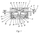
- Fig. 1 die Seitenansicht einer ersten Bauform des erfindungsgemäßen Uberlastsicherungsschalters mit geöffnetem Gehäuse;
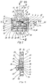
- Fig. 2 die entsprechende Seitenansicht einer zweiten Bauform des erfindungsgemäßen Überlast,sicherungs- schalters;
- Fig. 3 einen Schnitt durch das Gehäuse des Überlastsicherungsschalters entlang der Linie III-III von Fig. 2;
- Fig. 4 eine Draufsicht auf das Gehäuse des Überlastsicherungsschalters mit Blick in Richtung IV von Fig. 2;
- Fig. 5 einen Schnitt durch das Gehäuse des Überlastsicherungsschalters entlang der Linie V-V von Fig. 2;
- Fig. 6 eine Draufsicht auf eine Kontaktfahne des Überlastaicherungeschalters gemäß Fig. 2.
- 1 shows the side view of a first design of the overload protection switch according to the invention with the housing open;
- 2 shows the corresponding side view of a second design of the overload switch according to the invention;
- 3 shows a section through the housing of the overload protection switch along the line III-III of FIG. 2.
- Figure 4 is a plan view of the housing of the overload protection switch with a view in the direction IV of Fig. 2.
- 5 shows a section through the housing of the overload protection switch along the line VV of FIG. 2.
- 6 is a plan view of a contact tab of the overload protection switch according to FIG. 2.
Bezugnehmend zunächst auf Fig. 1 ist der erfindungsgemäße Überlastsicherungsschalter dem grundsätzlichen Aufbau nach skizziert. Der Uberlastsicherungsschalter besitzt ein Gehäuse 1, das einen temperaturabhängig schaltenden Stromunterbrecher enthält, der einen angeschlossen Verbraucher vor Überhitzung schützt. Als Stromunterbrecher kommt in erster Linie ein Bimetallschalter in Betracht. Dieser erhält ein Stück Bimetall 2, das eine thermische Verformung erfährt, wodurch Schaltkontakte 3 elektrisch miteinander verbunden, bzw. voneinander getrennt werden. Als Träger der Schaltkontakte 3 sind Kontaktfahnen 4 vorgesehen, die unverlierbar an dem Gehäuse 1 befestigt sind. Ein Ende 5 der Kontaktfahnen 4 ragt jeweils aus dem Gehäuse 1 heraus. Es dient zum Anschluß der elektrischen Versorgungsleitung, die zu dem zu sichernden Verbraucher führt. Eine Kontaktfahne 4 wird mit einem Netzleiter und die andere Kontaktfahne 4 mit einem zum Verbraucher führenden Leiter in Verbindung gebracht, wozu an den Enden 5 geeignete Kabelbefestigungsmittel vorgesehen sind. In Fig. 1 sind insofern zwei Klemmschrauben 6 angedeutet, die ein abisoliertes Kabelende gegen die Kontaktfahnen 4 pressen. Es können aber auch andere Einrichtungen zum vorzugsweise lötfreien Anschluß Verwendung finden, z.B. in Form von handelsüblichen Lüsterklemmen.Referring first to FIG. 1, the basic design of the overload protection switch according to the invention is sketched. The overload protection switch has a
Die Kontaktfahnen 4 ragen mit ihrem anderen Ende in das Gehäuse 1, wo sie auf gleicher Höhe im Abstand voneinander zu liegen kommen. Sie sind über eine Kontaktbrücke 7 aus leitendem Material miteinander verschaltet. Die Kontaktbrücke 7 liegt auf der Oberfläche der Kontaktfahnen 4 auf, und sie läßt sich durch Verformung des Bimetalls 2 davon abheben. Als Auflagepunkt der Kontaktbrücke ? dienen zwei kuppelförmige Kontaktaufsätze 8, die an den Kontaktfahnen 4 z.B. durch Prägen ausgeformt sind. Zur Erzielung eines geringen Übergangswiederstands empfiehlt es sich, die Kontaktaufsätze 8 zu versilbern. Die Kontaktbrücke ? ist in dem Gehäuse 1 bezüglich der Kontaktfahnen 4 beweglich-geführt. Sie wird an einer Stirnseite von einem Stößel 9 beaufschlagt, der eine kraftübertragende Verbindung zu dem Bimetallstück 2 herstellt. Der Stößel 9 gemäß Fig. 1 ist stempelförmig. Er weist einen zylindrischen Schaft 10 auf, der in einer passenden Gehäuseöffnung 11 axial beweglich geführt ist. An seinem der Kontaktbrücke 7 zugewandten Ende ist der Schaft 10 in Form einer ausladenden Stempelplatte 12 erweitert. Die Stempelplatte 12 liegt flächig an der Kontaktbrücke 7 an. Sie bildet zugleich einen Anschlag, der die Einschubtiefe des Stößels 9 in Richtung hin auf das Bimetallstück 2 begrenzt. Das gegenüberliegende axiale Ende des Schafts 10 bildet einen Fuß, mit dem der Stößel 9 mittig auf dem Bimetallstück 2 aufsteht.The other end of the
Das Bimetallstück 2 ist an seinem Rand membranartig an dem Gehäuse 1 gehaltert. Es hat vorzugsweise die Gestalt einer Kreisscheibe, und entsprechend ist das Gehäuse 1 mit einer umlaufenden Ringausnehmung 13 versehen, die den Rand des Bimetallstücks 2 aufnimmt. Das Bimetallstück 2 erstreckt sich frei durch eine Kammer 14 im Innern des Gehäuses 1, wobei das erforderliche Bewegungsspiel für die thermische Verformung des Bimetallstücks 2 gewährleistet ist. Fig. 1 zeigt das Bimetallstück 2 in einem von der Kontaktbrücke 7 weg gewölbten Zustand. Die Kontaktbrücke 7 liegt auf den Kontaktaufsätzen 8 auf, und zwischen den Kontaktfahnen 4 ist eine elektrische Verbindung über die Kontaktbrücke ? hergestellt; dies entspricht dem Normalzustand des erfindungsgemäßen Überlastsicherungsschalters, in dem der angeschlossene Verbraucher mit der vollen Netzspannung belastet ist. Tritt nun eine Überlastung des Verbrauchers ein, so erfolgt eine Erwärmung des Bimetallstücks 2, durch das dieses entgegen der in Fig. 1 gezeigten Wölbung deformiert wird. Der mittig auf dem Bimetallstück 2 aufsitzende Stößel 9 überträgt diese Verformung auf die Kontaktbrücke 7" die von den Kontaktaufsätzen 8 abgehoben wird. Diese Bewegung der Kontaktbrücke 7 erfolgt gegen die Kraft einer Rückstellfeder 15, die die Kontaktbrücke 7 auf der dem Stößel 9 abgewandten Stirnseite belastet. Die Rückstellfeder 15 ist in einer passenden Öffnung des Gehäuses 1 aufgenommen. Sie hat bügelförmige Gestalt und liegt mit ihrem Scheitel 16 an der Kontaktbrücke 7 an. Beidseits von dem Scheitel 16 erstrecken sich zwei symmetrische Federarme 17, die an ihren Enden gekrümmt sind und sich gegen einen Boden 18 des Gehäuses 1 abstützen. Eine axiale Hubbewegung des Stößels 9 zusammen mit der Kontaktbrücke 7 bewirkt ein Spreizen der Federarme 17, wodurch die Rückstellfeder 15 gespannt wird. Letztere überführt die Kontaktbrücke 7 in die Schließstellung, wenn das Bimetallstück 2 nach dem Abkühlen in die in Fig. 1 dargestellte Position zurückspringt.The
Der erfindungsgemäße überlastsicherungsschalter kehrt aber nur denn in die Normalstellung zurück, wenn zuvor der angeschlossene Verbraucher abgeschaltet oder in sonstiger Weise vom Netz getrennt wird. Diese Schutzwirkung, die ein unkontrolliertes Wiederanlaufen des Verbrauchers verhindert, wird mittels eines Heizwiderstands 19 im Innern des Gehäuses 1 erzielt. Der Heizwiderstand 19 ist dem Bimetallschalter elektrisch parallelgeschaltet, und er ist thermisch an das Bimetallstück 2 gekoppelt. Ein guter WärmeÜbergang von dem Heizwiderstand 19 auf das Bimetallstück 2 wird in dem dargestellten Ausführungsbeispiel dadurch gewährleistet, daß diese beiden Bauelemente in ein und derselben Kammer 14 des Gehäuses 1 angeordnet sind. Der Heizwiderstand 19 ist im wesentlichen parallel und in geringem Abstand zu dem Bimetallstück 2 an dem Gehäuse 1 festgelegt. Als Abstandshalter dienen Stege 20, die die Ringausnehmung 13 für die Bimetallscheibe 2 nach unten hin begrenzen. Die Stege 20 decken nur den randnahen Bereich des Bimetallstücks 2 ab, und ebenso steht auch nur der Rand des Heizwiderstands 19 mit den Stegen 20 in Anlage. Ein Mittelbereich des Heizwiderstands 19 ragt hingegen frei durch die Kammer 14 hindurch, so daß durch Konvektion und Strahlung ein ungehinderter Wärmeübergang auf das Bimetallstück 2 erfolgt. Gemäß einer bevorzugten Ausführungsform der Erfindung ist nur dieser Mittelbereich mit einer Wärme erzeugenden Widerstandsschicht 21 belegt, während die Randzonen des Heizwiderstands 19 nur zur Kontaktierung dienen.However, the overload protection switch according to the invention only returns to the normal position if the connected consumer has previously been switched off or otherwise disconnected from the mains. This protective effect, which prevents an uncontrolled restart of the consumer, is achieved by means of a
Der elektrische Anschluß des Heizwiderstands 19 erfolgt an den Kontaktfahnen 4. Montagetechnisch besonders vorteilhaft und materialsparend ist eine Bauform, bei der der Heizwiderstand 19 mittels zweier federnder Klemmbügel 22 zugleich in dem Gehäuse 1 gehalten und an die Kontaktfahnen 4 angeschlossen wird. Die Kontaktfahnen 4 weisen hierzu eine zweite Kontaktstelle auf, die ebenso wie die Kontaktaufsätze 8 zur Erzielung eines niedrigen Übergangswiderstands in geeigneter Weise beschichtet, und insbesondere versilbert sein kann. Die Kontaktstelle befindet sich an der den Kontaktaufsätzen 8 abgewandten Unterseite der Kontaktfahnen 4. Während sich die Kontaktaufsätze 8 in einem Mittelbereich des Gehäuses 1 befinden, liegen die Kontaktstellen für die Klemmbügel 22 dicht am Gehäuserand. Diese Anordnung berücksichtigt den Umstand, daß zwischen den Kontaktfahnen4 und dem Heizwiderstand 19 das Bimetallstück 2 in dem Gehäuse 1 gehaltert ist, und die Klemmbügel 22 an diesem Bimetallstück 2 vorbeigeführt werden müssen. Zu diesem Zweck ist randseitig neben der Ringausnehmung 13 für das Bimetallstück 2 ein Führungskanal 23 vorgesehen, in den sich die Klemmbügel 22 einsetzen lassen. Der Führungskanal 23 und die Ringausnehmung 13 sind dabei druch eine einstückig an dem Gehäuse 1 ausgeformte Rippe 24 voneinander getrennt. Der Führungskanal 23 mündet zu den Kontaktfahnen 4 hin in einen Hohlraum unterhalb der Anschlußstelle für den Klemmbügel 22, und an der gegenüberliegenden Seite endet der Führungskanal 23 unterhalb des Heizwiderstands 19 in der Kammer 14 des Gehäuses 1.The electrical connection of the
Der Heizwiderstand 19 hat in dem dargestellten Ausführungsbeispiel die Form eines flachen, länglichen Rechteckplättchens, dessen seitliche Randzonen zur Kontaktierung mit den Klemmbügeln 22 ausgelegt sind. Ein derartiger Heizwiderstand 19 wird vorzugsweise als Dickschichtwiderstand hergestellt. Er besteht aus einer Aluminiumoxydplatte, deren Randzonen. z.B. mit AgPd beschichtet und dessen Mittelbereich als Widerstandsfläche ausgebildet ist; letzteres kann beispielsweise dadurch geschehen, daß man den Mittelbereich mit einer Schicht Widerstandspaste belegt. Diese Bauform ist allerdings für die Erfindung nicht zwingend; als Heizwiderstand 19 kann vielmehr auch ein Widerstandsdraht oder eine aus Widerstandsdraht gewickelte Heizspirale Verwendung finden. Für die beschriebene, den Bimetallschalter sperrende Wirkung ist eine schnelle Erwärmung des Heizwiderstands 19 nach dem Öffnen der Kontaktbrücke 7 wünschenswert; diesem Ziel ist ein Widerstand mit positivem Temperaturkoeffizienten (PTC-Widerstand, Kaltleiter) besonders dienlich.In the exemplary embodiment shown, the
Die zum Anschluß des Heizwiderstands 19 dienenden Klemmbügel 22 stützen sich gegen einen Boden 25 des Gehäuses 1 ab und beaufschlagen mit Federspannung sowohl die Unterseite der Kontaktfahnen 4 als auch die Unterseite des Heizwiderstands 19. Die Klemmbügel 22 bestehen aus einem elektrisch leitenden Material, so daß eine elektrische Verbindung zwischen den Anschlußstellen an den Kontaktfahnen 4 und dem Heizwiderstand 19 hergestellt wird. Die Federspannung der Klemmbügel 22 sorgt für einen sicheren Kontakt; zugleich haben die Klemmbügel 22 aber auch eine mechanische Haltefunktion für den Heizwiderstand 19, den sie gegen die Stege 20 pressen. Die Klemmbügel 22 haben ein C-förmiges Profil. Ihr C-Rücken ist in dem Führungskanal 23 aufgenommen, während ihre gekrümmten C-Schenkel zur Kontaktierung an der Kontaktfahne 4 bzw. dem Heizwiderstand 19 dienen. Der mit dem Heizwiderstand 19 zur Anlage kommende C-Schenkel ist schlangenlinienförmig gewellt, so daß zwei Anlagepunkte 27 mit dem Boden 25 bestehen. Zwischen diesen Anlagepunkten 27 befindet sich ein einzelner Anlagepunkt 28 der C-Schenkel 26 an dem Heizwiderstand 19, auf den ein federnder Anpreßdruck ausgeübt wird.The serving for connecting the
Der erfindungsgemäße Überlast-sicherungsschalter zeichnet sich dadurch aus, daß alle seine Bauelemente in passenden Gehäuseausnehmungen aufgenommen und geführt sind, und daß sich die im Innern des Gehäuses liegenden elektrischen Anschlüsse lötfrei herstellen lassen. Hierdurch ist die Herstellung und der Zusammenbau des Überlastsicherungsschalters besonders einfach. In einer bevorzugten Ausführungsform besteht das Gehäuse 1 überdies aus zwei fast identischen Halbschalen, was die Fertigung weiter vereinfacht. Ein praktisches Ausführungsbeispiel eines derartigen Gehäuses wird nachstehend anhand von Fig. 2 bis 6 beschrieben, wobei gleiche Teile mit übereinstimmenden Bezugszeichen versehen sind.The overload safety switch according to the invention is characterized in that all of its components are received and guided in suitable housing recesses, and that the electrical connections located in the interior of the housing can be made without soldering. This makes the overload protection switch particularly easy to manufacture and assemble. In a preferred embodiment, the
In Fig. 2 ist der Blick auf eine geöffnete Halbschale des Gehäuses 1 gerichtet. Die Zeichenebene entspricht dabei der Trennebene der Halbschalen. In die Halbschale sind Bauelemente des Uberlastsicherungsschalters eingesetzt, die über die Trennebene hinausstehen und bei geschlossenem Gehäuse 1 in beiden Halbschalen gehaltert sind; diese Bauelemente erscheinen in Fig. 2 angeschnitten. Der Überlastsicherungsschalter besitzt wiederum zwei Kontaktfahnen 4, von denen in Fig. 2 nur die rechte dargestellt ist; die linke Halbseite der Fig. 2 zeigt dagegen den Schlitz 29 in dem Gehäuse 1, der die Kontaktfahnen 4 aufnimmt. Die Form der Verankerungen der Kontaktfahnen 4 in dem Gehäuse 1 entnimmt man Fig. 2, Fig. 3 und insbesondere Fig. 6. Demnach haben die Kontaktfahnen 4 einen etwa rechteckigen Grundriß, und an den Seitenkanten 30 sind zwei einander gegenüberliegende Kerben 31 ausgenommen. Im montierten Zustand sind die Kontaktfahnen 4 in den Schlitz 29 der Gehäuse-Halbschalen eingesetzt, wobei die Kerbe 31 auf der Höhe des Gehäuserands 32 zu liegen kommt. Die Schlitze 29 sind dabei so tief in das Vollmaterial der Gehäuse-Halbschalen gelegt, daß eine Nase 33 stehenbleibt (vgl. Fig. 3), die in die Kerben 31 einfällt. Die Kontaktfahnen 4, wie auch die übrigen Bauelemente des Überlastsicherungsschalters, werden zunächst in eine Halbschale des Gehäuses eingesetzt, und anschließend wird die andere Halbschale des Gehäuses 1 über ihnen geschlossen. Die Kontaktfahnen 4 werden dabei in ihren Kerben 31 durch Nasen 33 an beiden Halbschalen in dem Gehäuse 1 arretiert.2, the view is directed towards an open half-shell of the
Das aus dem Gehäuse 1 herausragende Ende 5 der Kontaktfahnen 4 ist mit einer Kabelbefestigungs-Vorrichtung in Gestalt zweier abgewinkelter Zacken 34 versehen, die mit einer Klemmschraube in einer Gewindebohrung 35 zusammenwirken. Die Zacken 34 setzen dabei an trapezförmig angeschrägten Vorderkanten der Kontaktfahlen 4 an, und sie ragen aus der Kontaktebene heraus nach unten. Andere Formen der Kabelbefestigung sind gleichfalls denkbar. Das Ende der Kontaktfahnen 4 im Innern des Gehäuses 1 trägt einen Kontaktaufsatz 8 in Gestalt einer kuppelförmigen Ausprägung; die zugehörige Gegenprägung auf der gegenüberliegenden Unterseite der Kontaktfahnen 4 ist in den Abbildungen nicht näher dargestellt. Die Kontaktfahnen 4 werden in den Halbschalen des Gehäuses 1 zwischen angeformten Stegen 36, 37 gehaltert. Der Steg 37 auf der Seite der Kontaktaufsätze 8 dient dabei zugleich als Führung der Kontaktbrücke 7 sowie als Auflage für die Rückstellfeder 15, die die Kontaktbrücke 7 beaufschlagt.The
Die Kontaktbrücke 7 ist im Querschnitt rechteckig und schmaler als die Kontaktfahnen 4. Sie ist an ihrer der Rückstellfeder 15 zugewandten Oberseite mit einer mittig ausgeformten Kugelkuppe 38 versehen, die z.B. durch Prägen aufgebracht sein kann. Die Kugelkuppe 38 dient zur Zentrierung der Rückstellfeder 15, die bügelförmig gestaltet ist und mit ihrem Scheitel 16 an der Kontaktbrücke 7 anliegt. Der Scheitel 16 ist komplementär zu der Kugelkuppe 38 mit einer Einbuchtung versehen, in der die Kugelkuppe 38 formschlüssig zu liegen kommt. Die Kontaktbrücke 7 und die Rückstellfeder 15 werden dadurch so ausgerichtet und aneinander festgelegt, daß stets eine zentrische Krafteinleitung auf die Kontaktbrücke 7 gewährleistet ist.The
Die Breite der Rückstellfeder 15 entspricht etwa der der Kontaktbrücke 7. Kontaktbrücke 7 und Rückstellfeder 15 liegen beide an dem Steg 37 an, der zu diesem Zweck stufenförmig auf zwei zueinander versetzten Ebenen im Innern des Gehäuses 1 verläuft. Bezugnehmend auf Fig. 2, Fig. 3 und Fig. 5 zeigt ein Blick von der Trennebene der Gehäuse-Halbschalen her (vgl. Fig. 2) im Hintergrund einen Halteabschnitt 39 des Stegs 37 mit, dem dieser die Kontaktfahnen 4 beaufschlagt. Dieser Halteabschnitt 39 erstreckt sich über die volle Länge der Kontaktfahnen 4zur Mitte des Gehäuses 1 hin. Von dem Halteabschnitt 39 springt in den Vordergrund der Fig. 2 stufenförmig ein Absatz 40 vor, der ein trapezförmiges Profil hat. Die zur Mitte des Gehäuses 1 gerichtete Stirnseite 41 des Absatzes 40 bildet einen seitlichen Anschlag für die Kontaktbrücke 7, die mit ihren Querseiten zwischen den Absätzen 40 geführt ist. Längsseitig ist die Kontaktbrücke 7 zwischen den Halteabschnitten 39 gelagert; zu diesem Zweck ist die Kontaktbrücke 7 schmaler als die Kontaktfahnen 4.The width of the
Die schräge Oberseite 42 des Absatzes 40 begrenzt eine Gehäusekammer, die die Rückstellfeder 15 aufnimmt. Die Neigung der Oberseite 42 ist dabei auf den Spreizwinkel der bügelförmigen Rückstellfeder 15 abgestimmt. Letztere hat, wie bereits erwähnt, in etwa dieselbe Breite wie die Kontaktbrücke 7. Sie wird daher zwischen der Oberfläche des Halteabschnitts 39, der schrägen Oberseite 42 des Absatzes 40 und dem Boden 18 des Gehäuses 1 unverlierbar gehalten.The inclined
Unterhalb der Kontaktebene ist in den Halbschalen des Gehäuses 1 eine halbzylindrische Ausnehmung 43 vorgesehen, die eine kreisrunde Bimetallscheibe 2 aufnimmt. Die Ausnehmung 43 ist dem Durchmesser nach abgestuft. Eine Partie größeren Durchmessers 44 auf halber Höhe der Ausnehmung 43 wird in Axialrichtung beidseits durch Partien 45 kleineren Durchmessers begrenzt. Die Partie größeren Durchmessers 44 nimmt den Rand der Bimetallscheibe 2 auf, und die Partien 45 kleineren Durchmessers gewährleisten das für die thermische Verformung erforderliche Bewegungsspiel. Die Bimetallscheibe 2 steht über einen Stößel 9 in kraftübertragender Verbindung mit der Kontaktbrücke 7. Der Stößel 9 ist in diesem Ausführungsbeispiel eine einfache Rundstange, der zwischen halbzylindrischen Führungsflächen der Gehäuse-Halbschalen aufgenommen ist.Below the contact plane, a
Unterhalb der Bimetallscheibe 2 ist in dem Gehäuse 1 ein Heizwiderstand 19 in Form einer rechteckigen Platte enthalten. Der Heizwiderstand 19 steht mit einer Rippe 24 in Anlage, die als Abstandshalter zu der Bimetallscheibe 2 dient. Er wird in dieser Stellung mittels zweier federnder Klemmbügel 22 arretiert, die zugleich eine elektrische Verbindung zu den Kontaktfahnen 4 herstellen. Die Klemmbügel 22 haben in dem dargestellten Ausführungsbeispiel das Profil eines an einer Grundlinie offenen Parallelogramms, und die Bügelenden sind kuppenförmig gerundet. Die Klemmbügel 22 werden mit ihrem Parallelogramm-Rücken 46 in einen Führungskanal der Gehäuse-Halbschalen eingesetzt, und die Parallelogramm-Schenkel 47 beaufschlagen federnd die Kontaktfahne 4 bzw. den Heizwiderstand 19, wobei ihr Anstellwinkel relativ zu dem Parallelogramm-Rücken 46 elastisch veränderlich ist.Below the
Die äußere Kontur der Gehäuse-Halbschalen folgt im wesentlichen der der enthaltenen Bauelemente. Wie bereits erwähnt, haben die Kontaktfahnen 4, die Kontaktbrücke 7, die Rückstellfeder 15 und der Heizwiderstand 19 einen rechteckigen Grundriß. Die zugehörige Partie der Gehäuse-Halbschalen hat entsprechend eine quaderförmige Gestalt.The outer contour of the housing half-shells essentially follows that of the components contained. As already mentioned, the contact lugs 4, the
Hingegen ist das Bimetallstück 2 eine Kreisscheibe. Sie wird in einer kreiszylindrischen Ausbuchtung 48 der Gehäuse-Halbschalen 1 aufgenommen. An die Gehäuse-Halbschalen sind weiterhin Laschen 49, 50 angeformt, vermittels derer die Halbschalen beim Zusammenbau des Gehäuses 1 aneinander montiert werden. Die Laschen 49, 50 bilden in dem dargestellten Ausführungsbeispiel quaderförmige Ansätze der Gehäuse-Halbschalen mit verminderter Breite und Dicke. Sie befinden sich oberhalb der Kontaktebene, bzw. unterhalb des Heizwiderstands 19, und sind mit Befestigungsmitteln in Gestalt zweier Nietlöcher 51 versehen. Die Lasche 49 unterhalb des Heizwiderstands 19 ist dabei kurz und im Material massiv. Die andere Lasche 50 ist dagegen nach oben hin verlängert und als Hohlkörper gestaltet, wobei nur in der Umgebung des Nietlochs 51 einstatzenförmiger Materialsteg 52 vorgesehen ist.In contrast, the
Zum Zusammenbau des erfindungsgemäßen Überlastsicherungsschalters werden zunächst alle erwähnten Bauelemente - Kontaktfahnen 4, Kontaktbrücke 7, Rückstellfeder 15, Stößel 9, Bimetallscheibe 2, Heizwiderstand 19 und Klemmbügel 22 - in die zugehörigen Gehäuse-Ausnehmungen der einen Halbschale eingesetzt. Die Bauelemente greifen mit etwa der Hälfte ihrer Breite in diese Halbschale ein und stehen im übrigen über die Trennebene der Halbschalen hinaus. Sodann wird die zweite Halbschale aufgestülpt, die ganz entsprechende Ausnehmungen für die Bauelemente aufweist, und die beiden Halbschalen werden miteinander vernietet. Die Halterungs- und Führungsstrukturen für die Bauelemente im Innern der Halbschalen sind samt und sonders gegenüber der Trennebene rückversetzt; die Halbschalen kommen daher nur im Bereich ihres Gehäuserands 32 sowie in der Umgebung der Nietlöcher 51 miteinander zur Anlage. Einer bevorzugten Weiterbildung der Erfindung gemäß können die Halbschalen dabei an ihrer Berührfläche mit komplementären Führungsstrukturen versehen sein, die nach dem Prinzip von Nut und Feder miteinander zum Eingriff kommen und die Halbschalen beim Zusammenbau positionieren. In dem dargestellten Ausführungsbeispiel (vgl. Fig. 2 und Fig. 4) trägt dementsprechend der Gehäuserand 32 auf einer Halbseite jeder Halbschale einen Steg 53 mit dreieckigem Querschnitt, und der Gehäuserand 32 auf der anderen Halbseite ist mit einer komplementären Dreiecksnut 54 versehen. Der Steg 53 der einen Halbschale fällt beim Zusammenbau in die Dreiecksnut 54 der anderen Halbschale ein, wodurch eine präzise Ausrichtung der Halbschalen gewährleistet ist.To assemble the overload protection switch according to the invention, all of the components mentioned -
Claims (15)
Priority Applications (3)
| Application Number | Priority Date | Filing Date | Title |
|---|---|---|---|
| DE8484106193T DE3478973D1 (en) | 1984-05-30 | 1984-05-30 | Overload protection switch |
| AT84106193T ATE44630T1 (en) | 1984-05-30 | 1984-05-30 | OVERLOAD PROTECTION SWITCH. |
| EP84106193A EP0162940B1 (en) | 1984-05-30 | 1984-05-30 | Overload protection switch |
Applications Claiming Priority (1)
| Application Number | Priority Date | Filing Date | Title |
|---|---|---|---|
| EP84106193A EP0162940B1 (en) | 1984-05-30 | 1984-05-30 | Overload protection switch |
Publications (2)
| Publication Number | Publication Date |
|---|---|
| EP0162940A1 true EP0162940A1 (en) | 1985-12-04 |
| EP0162940B1 EP0162940B1 (en) | 1989-07-12 |
Family
ID=8191958
Family Applications (1)
| Application Number | Title | Priority Date | Filing Date |
|---|---|---|---|
| EP84106193A Expired EP0162940B1 (en) | 1984-05-30 | 1984-05-30 | Overload protection switch |
Country Status (3)
| Country | Link |
|---|---|
| EP (1) | EP0162940B1 (en) |
| AT (1) | ATE44630T1 (en) |
| DE (1) | DE3478973D1 (en) |
Cited By (4)
| Publication number | Priority date | Publication date | Assignee | Title |
|---|---|---|---|---|
| EP0284916A2 (en) * | 1987-03-31 | 1988-10-05 | Ulrika Hofsäss | Thermostat with a housing |
| DE3802647A1 (en) * | 1988-01-29 | 1989-08-03 | Lectra Trading Ag | Device for indicating the switching condition of an overload circuit breaker |
| EP0903836A2 (en) * | 1997-09-22 | 1999-03-24 | G. Kienzler AG | Thermal protection switch |
| CN112534537A (en) * | 2018-08-27 | 2021-03-19 | 柏恩氏株式会社 | Circuit breaker, safety circuit and secondary battery pack |
Citations (4)
| Publication number | Priority date | Publication date | Assignee | Title |
|---|---|---|---|---|
| DE1488895C (en) * | 1972-04-20 | Danfoss A/S, Nordborg (Danemark) | Excess temperature release, especially fuse | |
| DE1490815B2 (en) * | 1964-09-26 | 1972-05-18 | Texas Instruments Ine, Dallas, Tex (VStA) | SELF SWITCH WITH A PUSH BUTTON AXIAL MOVABLE AGAINST THE PRESSURE OF A SPRING |
| US4048611A (en) * | 1976-06-23 | 1977-09-13 | Kuczynski Walter J | Thermal switch |
| DE2752430A1 (en) * | 1977-11-24 | 1979-05-31 | Braun Ag | CIRCUIT BREAKER |
Family Cites Families (1)
| Publication number | Priority date | Publication date | Assignee | Title |
|---|---|---|---|---|
| US2369986A (en) * | 1942-07-21 | 1945-02-20 | Gen Electric | Electric protective means |
-
1984
- 1984-05-30 DE DE8484106193T patent/DE3478973D1/en not_active Expired
- 1984-05-30 EP EP84106193A patent/EP0162940B1/en not_active Expired
- 1984-05-30 AT AT84106193T patent/ATE44630T1/en not_active IP Right Cessation
Patent Citations (4)
| Publication number | Priority date | Publication date | Assignee | Title |
|---|---|---|---|---|
| DE1488895C (en) * | 1972-04-20 | Danfoss A/S, Nordborg (Danemark) | Excess temperature release, especially fuse | |
| DE1490815B2 (en) * | 1964-09-26 | 1972-05-18 | Texas Instruments Ine, Dallas, Tex (VStA) | SELF SWITCH WITH A PUSH BUTTON AXIAL MOVABLE AGAINST THE PRESSURE OF A SPRING |
| US4048611A (en) * | 1976-06-23 | 1977-09-13 | Kuczynski Walter J | Thermal switch |
| DE2752430A1 (en) * | 1977-11-24 | 1979-05-31 | Braun Ag | CIRCUIT BREAKER |
Cited By (8)
| Publication number | Priority date | Publication date | Assignee | Title |
|---|---|---|---|---|
| EP0284916A2 (en) * | 1987-03-31 | 1988-10-05 | Ulrika Hofsäss | Thermostat with a housing |
| EP0284916A3 (en) * | 1987-03-31 | 1990-06-13 | Peter Hofsass | Thermostat with a housing |
| DE3802647A1 (en) * | 1988-01-29 | 1989-08-03 | Lectra Trading Ag | Device for indicating the switching condition of an overload circuit breaker |
| DE3802647C2 (en) * | 1988-01-29 | 1998-02-05 | Lectra Trading Ag | Display device for the switching state of a circuit breaker |
| EP0903836A2 (en) * | 1997-09-22 | 1999-03-24 | G. Kienzler AG | Thermal protection switch |
| EP0903836A3 (en) * | 1997-09-22 | 2000-05-17 | G. Kienzler AG | Thermal protection switch |
| CN112534537A (en) * | 2018-08-27 | 2021-03-19 | 柏恩氏株式会社 | Circuit breaker, safety circuit and secondary battery pack |
| CN112534537B (en) * | 2018-08-27 | 2024-04-23 | 柏恩氏株式会社 | Circuit breaker, safety circuit and secondary battery pack |
Also Published As
| Publication number | Publication date |
|---|---|
| EP0162940B1 (en) | 1989-07-12 |
| DE3478973D1 (en) | 1989-08-17 |
| ATE44630T1 (en) | 1989-07-15 |
Similar Documents
| Publication | Publication Date | Title |
|---|---|---|
| DE69507848T2 (en) | Compact protective device | |
| DE3688800T2 (en) | Protection systems for a refrigeration compressor motor. | |
| EP0887826B1 (en) | Thermally actuated switch with contact bridge | |
| EP2601715B1 (en) | Thermal overload protection apparatus | |
| DE19941190B4 (en) | Thermal fuse | |
| EP2619784B1 (en) | Miniature safety switch | |
| EP2511930B1 (en) | Temperature protective switch | |
| DE102011101862B4 (en) | Temperature-dependent switch with current transfer element | |
| EP0920044B1 (en) | Switch with a temperature sensitive switching mechanism | |
| DE10081191B4 (en) | Thermal protector | |
| EP2304757A1 (en) | Bimetallic part and temperature-dependent switch equipped therewith | |
| EP0951040B1 (en) | Thermally actuated switch | |
| DE10151107A1 (en) | Thermal protector for fan heater, has heat generating resistor interposed between contact portions, such that electrodes of resistor are brought into contact with respective contact portions | |
| EP0994497B1 (en) | Switch with insulating support | |
| DE3526785C1 (en) | Push-button operated overcurrent protection switch | |
| DE3233909A1 (en) | SNAP DEVICE, ESPECIALLY ELECTRIC SNAP SWITCH | |
| DE69505884T2 (en) | Devices with resistance elements and temperature protection device for use therefor | |
| EP0162940B1 (en) | Overload protection switch | |
| EP0938116B1 (en) | Switch | |
| DE2448026C3 (en) | Directly heated bimetal strip for thermal tripping of an overcurrent switch | |
| EP2843680B1 (en) | Temperature-dependent switch | |
| DE2502579C2 (en) | PUSH BUTTON ACTUATED OVERCURRENT SWITCH WITH THERMAL RELEASE | |
| WO2001031749A2 (en) | Connector | |
| DE2261816A1 (en) | ELECTRIC CONTROL SWITCH | |
| DE3587064T2 (en) | THERMOSTAT. |
Legal Events
| Date | Code | Title | Description |
|---|---|---|---|
| PUAI | Public reference made under article 153(3) epc to a published international application that has entered the european phase |
Free format text: ORIGINAL CODE: 0009012 |
|
| AK | Designated contracting states |
Designated state(s): AT BE CH DE FR GB LI NL |
|
| 17P | Request for examination filed |
Effective date: 19860430 |
|
| 17Q | First examination report despatched |
Effective date: 19870902 |
|
| GRAA | (expected) grant |
Free format text: ORIGINAL CODE: 0009210 |
|
| AK | Designated contracting states |
Kind code of ref document: B1 Designated state(s): AT BE CH DE FR GB LI NL |
|
| PG25 | Lapsed in a contracting state [announced via postgrant information from national office to epo] |
Ref country code: NL Effective date: 19890712 Ref country code: BE Effective date: 19890712 |
|
| REF | Corresponds to: |
Ref document number: 44630 Country of ref document: AT Date of ref document: 19890715 Kind code of ref document: T |
|
| REF | Corresponds to: |
Ref document number: 3478973 Country of ref document: DE Date of ref document: 19890817 |
|
| GBT | Gb: translation of ep patent filed (gb section 77(6)(a)/1977) | ||
| ET | Fr: translation filed | ||
| NLV1 | Nl: lapsed or annulled due to failure to fulfill the requirements of art. 29p and 29m of the patents act | ||
| PLBE | No opposition filed within time limit |
Free format text: ORIGINAL CODE: 0009261 |
|
| STAA | Information on the status of an ep patent application or granted ep patent |
Free format text: STATUS: NO OPPOSITION FILED WITHIN TIME LIMIT |
|
| 26N | No opposition filed | ||
| PGFP | Annual fee paid to national office [announced via postgrant information from national office to epo] |
Ref country code: GB Payment date: 19910426 Year of fee payment: 8 |
|
| PGFP | Annual fee paid to national office [announced via postgrant information from national office to epo] |
Ref country code: FR Payment date: 19910430 Year of fee payment: 8 |
|
| PGFP | Annual fee paid to national office [announced via postgrant information from national office to epo] |
Ref country code: AT Payment date: 19910514 Year of fee payment: 8 |
|
| PGFP | Annual fee paid to national office [announced via postgrant information from national office to epo] |
Ref country code: CH Payment date: 19910829 Year of fee payment: 8 |
|
| PG25 | Lapsed in a contracting state [announced via postgrant information from national office to epo] |
Ref country code: GB Effective date: 19920530 Ref country code: AT Effective date: 19920530 |
|
| PG25 | Lapsed in a contracting state [announced via postgrant information from national office to epo] |
Ref country code: LI Effective date: 19920531 Ref country code: CH Effective date: 19920531 |
|
| GBPC | Gb: european patent ceased through non-payment of renewal fee |
Effective date: 19920530 |
|
| PG25 | Lapsed in a contracting state [announced via postgrant information from national office to epo] |
Ref country code: FR Effective date: 19930129 |
|
| REG | Reference to a national code |
Ref country code: CH Ref legal event code: PL |
|
| REG | Reference to a national code |
Ref country code: FR Ref legal event code: ST |
|
| PGFP | Annual fee paid to national office [announced via postgrant information from national office to epo] |
Ref country code: DE Payment date: 20030424 Year of fee payment: 20 |