EP3229254B1 - Vacuum interrupter for a vacuum circuit breaker - Google Patents
Vacuum interrupter for a vacuum circuit breaker Download PDFInfo
- Publication number
- EP3229254B1 EP3229254B1 EP16207568.3A EP16207568A EP3229254B1 EP 3229254 B1 EP3229254 B1 EP 3229254B1 EP 16207568 A EP16207568 A EP 16207568A EP 3229254 B1 EP3229254 B1 EP 3229254B1
- Authority
- EP
- European Patent Office
- Prior art keywords
- envelope
- insulating envelope
- circuit breaker
- shield
- vacuum
- Prior art date
- Legal status (The legal status is an assumption and is not a legal conclusion. Google has not performed a legal analysis and makes no representation as to the accuracy of the status listed.)
- Revoked
Links
- 238000003466 welding Methods 0.000 claims description 7
- 238000004519 manufacturing process Methods 0.000 description 7
- 239000000919 ceramic Substances 0.000 description 6
- 230000015556 catabolic process Effects 0.000 description 4
- 238000009413 insulation Methods 0.000 description 4
- 238000005219 brazing Methods 0.000 description 3
- 230000005684 electric field Effects 0.000 description 3
- 239000011521 glass Substances 0.000 description 2
- 238000012986 modification Methods 0.000 description 2
- 230000004048 modification Effects 0.000 description 2
- 230000000903 blocking effect Effects 0.000 description 1
- 238000012423 maintenance Methods 0.000 description 1
- 239000002184 metal Substances 0.000 description 1
- 238000000034 method Methods 0.000 description 1
- 229910001220 stainless steel Inorganic materials 0.000 description 1
- 239000010935 stainless steel Substances 0.000 description 1
Images

Classifications
-
- H—ELECTRICITY
- H01—ELECTRIC ELEMENTS
- H01H—ELECTRIC SWITCHES; RELAYS; SELECTORS; EMERGENCY PROTECTIVE DEVICES
- H01H33/00—High-tension or heavy-current switches with arc-extinguishing or arc-preventing means
- H01H33/60—Switches wherein the means for extinguishing or preventing the arc do not include separate means for obtaining or increasing flow of arc-extinguishing fluid
- H01H33/66—Vacuum switches
- H01H33/662—Housings or protective screens
- H01H33/66261—Specific screen details, e.g. mounting, materials, multiple screens or specific electrical field considerations
-
- H—ELECTRICITY
- H01—ELECTRIC ELEMENTS
- H01H—ELECTRIC SWITCHES; RELAYS; SELECTORS; EMERGENCY PROTECTIVE DEVICES
- H01H33/00—High-tension or heavy-current switches with arc-extinguishing or arc-preventing means
- H01H33/60—Switches wherein the means for extinguishing or preventing the arc do not include separate means for obtaining or increasing flow of arc-extinguishing fluid
- H01H33/66—Vacuum switches
- H01H33/662—Housings or protective screens
- H01H33/66207—Specific housing details, e.g. sealing, soldering or brazing
-
- H—ELECTRICITY
- H01—ELECTRIC ELEMENTS
- H01H—ELECTRIC SWITCHES; RELAYS; SELECTORS; EMERGENCY PROTECTIVE DEVICES
- H01H33/00—High-tension or heavy-current switches with arc-extinguishing or arc-preventing means
- H01H33/60—Switches wherein the means for extinguishing or preventing the arc do not include separate means for obtaining or increasing flow of arc-extinguishing fluid
- H01H33/66—Vacuum switches
- H01H33/664—Contacts; Arc-extinguishing means, e.g. arcing rings
-
- H—ELECTRICITY
- H01—ELECTRIC ELEMENTS
- H01H—ELECTRIC SWITCHES; RELAYS; SELECTORS; EMERGENCY PROTECTIVE DEVICES
- H01H33/00—High-tension or heavy-current switches with arc-extinguishing or arc-preventing means
- H01H33/60—Switches wherein the means for extinguishing or preventing the arc do not include separate means for obtaining or increasing flow of arc-extinguishing fluid
- H01H33/66—Vacuum switches
- H01H33/662—Housings or protective screens
- H01H33/66261—Specific screen details, e.g. mounting, materials, multiple screens or specific electrical field considerations
- H01H2033/66276—Details relating to the mounting of screens in vacuum switches
-
- H—ELECTRICITY
- H01—ELECTRIC ELEMENTS
- H01H—ELECTRIC SWITCHES; RELAYS; SELECTORS; EMERGENCY PROTECTIVE DEVICES
- H01H33/00—High-tension or heavy-current switches with arc-extinguishing or arc-preventing means
- H01H33/60—Switches wherein the means for extinguishing or preventing the arc do not include separate means for obtaining or increasing flow of arc-extinguishing fluid
- H01H33/66—Vacuum switches
- H01H33/662—Housings or protective screens
- H01H33/66261—Specific screen details, e.g. mounting, materials, multiple screens or specific electrical field considerations
- H01H2033/66284—Details relating to the electrical field properties of screens in vacuum switches
-
- H—ELECTRICITY
- H01—ELECTRIC ELEMENTS
- H01H—ELECTRIC SWITCHES; RELAYS; SELECTORS; EMERGENCY PROTECTIVE DEVICES
- H01H33/00—High-tension or heavy-current switches with arc-extinguishing or arc-preventing means
- H01H33/60—Switches wherein the means for extinguishing or preventing the arc do not include separate means for obtaining or increasing flow of arc-extinguishing fluid
- H01H33/66—Vacuum switches
- H01H33/662—Housings or protective screens
- H01H33/66261—Specific screen details, e.g. mounting, materials, multiple screens or specific electrical field considerations
- H01H2033/66292—Details relating to the use of multiple screens in vacuum switches
Definitions
- the present invention relates to a vacuum interrupter for a vacuum circuit breaker, and more particularly, to a vacuum interrupter for a vacuum circuit breaker, in which a center shield provided in the vacuum interrupter is arranged on the same line as an insulating envelope to reduce a full size of the insulating envelope and save the manufacturing cost.
- a circuit breaker and a switch are devices for directly controlling power supply to load by opening or closing an electric circuit in a power system.
- a circuit breaker having a capability of blocking a fault current including a load current and a switch for opening or closing a load current have been widely used.
- This circuit breaker is categorized into a hydraulic circuit breaker, an air circuit breaker, a gas circuit breaker, and a vacuum circuit breaker in accordance with an insulating medium of a core portion.
- the vacuum circuit breaker has a small size, high reliability, excellent multi-frequency switching characteristic and easiness in maintenance, whereby a vacuum circuit breaker having high voltage high capacity as well as a vacuum circuit breaking having medium voltage low capacity has been widely used.
- the vacuum interrupter is used as a breaker of the vacuum circuit breaker, and is installed inside a housing assembly body and senses a current or voltage generated on a high-tension line of a high-tension circuit through a converter. And, if a switching driver performs straight line reciprocating motion for an operator to change a switching state of the high-tension circuit, an actuating electrode portion of the vacuum interrupter, which is installed at one side of the operator, is in contact with and detached from a fixed electrode portion to supply and block a power.
- Background art examples of vacuum circuit breakers are disclosed in US 2003/141282 A1 , DE 93 17 827 U1 , DE 197 53 031 C1 , and JP 2004 253256 .
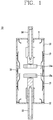
- FIG. 1 is a cross-sectional view illustrating a vacuum interrupter 10 provided in a vacuum circuit breaker of the related art.
- the vacuum interrupter 10 of the related art includes an insulating envelope 13 made of four ceramics and sealed with a fixed flange 11 and an actuating flange 12, a fixed electrode portion 14 having a fixed electrode 14a at one end, an actuating electrode portion 15 provided with an actuating electrode 15a which is in contact with or detached from the fixed electrode portion 14, a center shield 16 and an auxiliary shield 17, wherein the fixed electrode portion 14 and the actuating electrode portion 15 are arranged inside the insulating envelope 13 to mutually face each other.
- the center shield 16 is arranged at the center between the actuating electrode 15a and the fixed electrode 14a inside the insulating envelope 13, and the auxiliary shield 17 is provided at each of upper and lower sides of the center shield 16 inside the insulating envelope 13.
- the vacuum interrupter 10 for the vacuum circuit breaker which is configured as above, has problems as follows. That is, since the center shield 16 and the auxiliary shield 17 are arranged inside the insulating envelope 13, an inner diameter of the insulating envelope 13 should be greater than an outer diameter of each shield 16, 17, whereby a problem occurs in that the insulating envelope 13 in which each shield 16, 17 is received should be manufactured at a great size.
- the size of the vacuum interrupter 10 is increased, the amount of use of ceramic is increased, whereby a problem occurs in that the manufacturing cost of the vacuum interrupter is greatly increased.
- an object of the present invention is to solve the aforementioned problems.
- Another object of the present invention is to provide a vacuum interrupter for a vacuum circuit breaker, in which a center shield provided in the vacuum interrupter is arranged on the same line as an insulating envelope to reduce a size of the insulating envelope and save the manufacturing cost.
- a vacuum interrupter according to the present invention is defined in claim 1.
- the vacuum interrupter for a vacuum circuit breaker further comprises a first auxiliary shield provided inside the upper insulating envelope and the lower insulating envelope.
- the center shield has an outer diameter the same as or greater than an inner diameter of each of the upper insulating envelope and the lower insulating envelope.
- a fixed electrode is formed at one end of the fixed electrode portion
- an actuating electrode which is in contact with or detached from the fixed electrode, is formed at one end of the actuating electrode portion
- the center shield has an inner diameter greater than a sum of an outer diameter of the fixed electrode or the actuating electrode and a distance between the respective electrodes.
- the first auxiliary shield is provided with a fixed portion
- the upper insulating envelope includes a first upper envelope and a second upper envelope arranged below the first upper envelope to allow the fixed portion to be fitted between the first upper envelope and the second upper envelope
- the lower insulating envelope includes a first lower envelope and a second lower envelope arranged below the first lower envelope to allow the fixed portion to be fitted between the first lower envelope and the second lower envelope.
- upper and lower lengths of the first upper envelope and the second lower envelope are the same as those of the second upper envelope and the first lower envelope.
- a second auxiliary shield is formed respectively between the upper insulating envelope and the center shield and between the lower insulating envelope and the center shield.
- the second auxiliary shield is provided with a protrusion which is formed to be outwardly protruded.
- the protrusion is formed in a single body with the second auxiliary shield or connected with the second auxiliary shield through welding.
- the protrusion has one end formed to be inwardly bent in a circular shape or curved shape.
- a flange is provided above the upper insulating envelope and below the lower insulating envelope to seal the insides of the upper insulating envelope and the lower insulating envelope.
- the vacuum interrupter for a vacuum circuit breaker allows the center shield to be arranged between the upper insulating envelope and the lower insulating envelope, whereby upper and lower lengths of the respective insulating envelopes are reduced.
- the center shield is arranged between the upper insulating envelope and the lower insulating envelope, whereby the center shield is not provided inside each of the insulating envelopes and thus outer diameters of the respective insulating envelopes are reduced.
- the second auxiliary shield is provided with the protrusion and one end of the protrusion is formed in a bent circular shape or curved shape, concentration of electric field is prevented from occurring at the junction area of the center shield, the upper insulating envelope and the lower insulating envelope, that is, the junction area through brazing welding, whereby partial discharge or breakdown of insulation is prevented from occurring at the junction area.
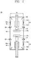
- FIG. 2 is a cross-sectional view illustrating a vacuum interrupter provided in a vacuum circuit breaker according to the present invention
- FIG. 3 is a cross-sectional view illustrating a vacuum interrupter provided in a vacuum circuit breaker according to another embodiment of the present invention
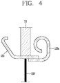
- FIG. 4 is a partially enlarged view illustrating a second auxiliary shield of a vacuum interrupter provided in a vacuum circuit breaker according to the present invention.
- a vacuum interrupter 100 for a vacuum circuit breaker includes an upper insulating envelope 111, a lower insulating envelope 113, a fixed electrode portion 115, an actuating electrode portion 117, a center shield 119, and a first auxiliary shield 121.
- the upper insulating envelope 111 is made of ceramic or reinforced glass, and constitutes upper side enclosure such that the fixed electrode portion 115 is arranged inside the upper insulating envelope 111.
- the lower insulating envelope 113 is made of ceramic or reinforced glass, and constitutes lower side enclosure such that the actuating electrode portion 117 is arranged inside the lower insulating envelope 113.
- the fixed electrode portion 115 is provided inside the upper insulating envelope 111, and includes a fixed electrode 115a at one end thereof and thus is in contact with or detached from the actuating electrode portion 117 in accordance with movement of the actuating electrode portion 117.
- the actuating electrode portion 117 is installed inside the lower insulating envelope 113 to face the fixed electrode portion 115, and includes an actuating electrode 117a at one end thereof and thus is in contact with or detached from the fixed electrode portion 115 in accordance with up and down movement.
- the center shield 119 is used so that metal steam generated during current breaking is not deposited on an inner wall of each insulating envelope 111, 113, and is made of stainless steel or Cu and arranged between the upper insulating envelope 111 and the lower insulating envelope 113.
- the center shield 119 is connected to each of one end and the other end of the upper insulating envelope 111 and the lower insulating envelope 113 through welding such as blazing, and constitutes enclosure of a center to receive the fixed electrode portion 115 and the actuating electrode portion 117 therein.
- the center shield 119 is not provided inside each insulating envelope 111, 113 but arranged between the upper insulating envelope 111 and the lower insulating envelope 113, whereby an inner diameter of each insulating envelope 111, 113 becomes smaller.
- an outer diameter D1 of the center shield 119 is formed to be the same as or greater than inner diameters D2 and D2 of the upper insulating envelope 111 and the lower insulating envelope 113.
- the diameter D1 of the center shield 119 is formed to be smaller than an outer diameter (not shown) of each of the upper insulating envelope 111 and the lower insulating envelope 113.
- the outer diameter D1 of the center shield 119 may be formed to be greater than the outer diameter of each of the upper insulating envelope 111 and the lower insulating envelope 113.
- an inner diameter of the center shield 119 is formed to be greater than a sum of an outer diameter D4 of the fixed electrode 115a or the actuating electrode 117a and a distance D5 between the respective electrodes, whereby the center shield 119 is sufficiently spaced apart from each of the electrodes 115a and 117a.
- the current is prevented from entering the actuating electrode 117a through the center shield 119 from the fixed electrode 115a and thus breakdown of insulation is prevented from occurring in the vacuum interrupter 100.
- the first auxiliary shield 121 is provided respectively inside each of the upper insulating envelope 111 and the lower insulating envelope 113.
- the first auxiliary shield 121 is provided with a fixed portion 121a formed to be fitted between a first upper envelope 111a and a second upper envelope 111b or between a first lower envelope 113a and a second lower envelope 113b, which will be described later.
- the upper insulating envelope 111 includes the first upper envelope 111a, and the second upper envelope 111b arranged below the first upper envelope 111a.
- the first auxiliary shield 121 is arranged to be tightly adhered to the upper insulating envelope 111.
- the lower insulating envelope 113 includes the first lower envelope 113a, and the second lower envelope 113b arranged below the first lower envelope 113a.
- the first auxiliary shield 121 is arranged inside the lower insulating envelope 113.
- upper and lower lengths L1 and L4 of the first upper envelope 111a and the second lower envelope 113b are formed to be the same as each other, and upper and lower lengths L2 and L3 of the second upper envelope 111b and the first lower envelope 113a are also formed to be the same as each other.
- a voltage for applying a current may be applied to an upper side where the first upper envelope 111a and the second upper envelope 111b are arranged or a lower side where the first lower envelope 113a and the second lower envelope 113b are arranged
- the respective upper envelopes 111a and 111b and the respective lower envelopes 113a and 113b corresponding to the respective upper envelopes 111a and 111b are formed to have the same size having insulating performance suitable for the applied voltage, whereby insulating performance is maintained uniformly regardless of the fact that the voltage is applied to the upper side or the lower side.
- a second auxiliary shield 123 is formed respectively between the upper insulating envelope 111 and the center shield 119 and between the lower insulating envelope 113 and the center shield 119.
- the second auxiliary shield 123 is provided with a protrusion 123a formed to be protruded toward the outside, wherein one end of the protrusion 123a is bent inwardly in a circular shape or curved shape. ?
- the protrusion 123a may be formed in a single body with the second auxiliary shield 123, or may be manufactured separately to be mutually connected with the second auxiliary shield 123 through welding.
- one end of the protrusion 123a is bent and formed in a circular shape or curved shape, concentration of electric field is prevented from occurring at a junction area of the center shield 119, the upper insulating envelope 111 and the lower insulating envelope 113, that is, a junction area through brazing welding, whereby partial discharge or breakdown of insulation is prevented from occurring at the junction area.
- a flange 130 is provided above the upper insulating envelope 111 and below the lower insulating envelope 113, whereby the upper end of the upper insulating envelope 111 and the lower end of the lower insulating envelope 113 are blocked by the flange 130 and thus their insides are sealed.
- the vacuum interrupter 100 for a vacuum circuit breaker which is configured and operated as above, allows the center shield 119 to be arranged between the upper insulating envelope 111 and the lower insulating envelope 113, whereby upper and lower lengths of the respective insulating envelopes 111 and 113 are reduced.
- the center shield 119 is arranged between the upper insulating envelope 111 and the lower insulating envelope 113, whereby the center shield 119 is not provided inside each of the insulating envelopes 111 and 113 and thus outer diameters of the respective insulating envelopes 111 and 113 are reduced.
- the upper and lower lengths and the outer diameters of the insulating envelopes 111 and 113 are reduced, a full size of the insulating envelopes 111 and 113 is reduced, whereby the amount of ceramic used to manufacture the insulating envelopes 111 and 113 is reduced and thus the manufacturing cost is saved remarkably.
- the second auxiliary shield 123 is provided with the protrusion 123a and one end of the protrusion 123a is bent to be formed in a circular shape or curved shape, concentration of electric field is prevented from occurring at the junction area of the center shield 119, the upper insulating envelope 111 and the lower insulating envelope 113, that is, the junction area through brazing welding, whereby partial discharge or breakdown of insulation is prevented from occurring at the junction area.
Landscapes
- High-Tension Arc-Extinguishing Switches Without Spraying Means (AREA)
Description
- The present invention relates to a vacuum interrupter for a vacuum circuit breaker, and more particularly, to a vacuum interrupter for a vacuum circuit breaker, in which a center shield provided in the vacuum interrupter is arranged on the same line as an insulating envelope to reduce a full size of the insulating envelope and save the manufacturing cost.
- Generally, a circuit breaker and a switch are devices for directly controlling power supply to load by opening or closing an electric circuit in a power system. As examples of the circuit breaker and the switch, a circuit breaker having a capability of blocking a fault current including a load current and a switch for opening or closing a load current have been widely used.
- This circuit breaker is categorized into a hydraulic circuit breaker, an air circuit breaker, a gas circuit breaker, and a vacuum circuit breaker in accordance with an insulating medium of a core portion.
- Among the circuit breakers, the vacuum circuit breaker has a small size, high reliability, excellent multi-frequency switching characteristic and easiness in maintenance, whereby a vacuum circuit breaker having high voltage high capacity as well as a vacuum circuit breaking having medium voltage low capacity has been widely used.
- Meanwhile, the vacuum interrupter is used as a breaker of the vacuum circuit breaker, and is installed inside a housing assembly body and senses a current or voltage generated on a high-tension line of a high-tension circuit through a converter. And, if a switching driver performs straight line reciprocating motion for an operator to change a switching state of the high-tension circuit, an actuating electrode portion of the vacuum interrupter, which is installed at one side of the operator, is in contact with and detached from a fixed electrode portion to supply and block a power. Background art examples of vacuum circuit breakers are disclosed in
US 2003/141282 A1 ,DE 93 17 827 U1 ,DE 197 53 031 C1 , andJP 2004 253256 -
FIG. 1 is a cross-sectional view illustrating avacuum interrupter 10 provided in a vacuum circuit breaker of the related art. - As shown in
FIG. 1 , thevacuum interrupter 10 of the related art includes aninsulating envelope 13 made of four ceramics and sealed with a fixedflange 11 and an actuatingflange 12, afixed electrode portion 14 having afixed electrode 14a at one end, an actuatingelectrode portion 15 provided with an actuatingelectrode 15a which is in contact with or detached from thefixed electrode portion 14, acenter shield 16 and anauxiliary shield 17, wherein thefixed electrode portion 14 and the actuatingelectrode portion 15 are arranged inside the insulatingenvelope 13 to mutually face each other. - At this time, the
center shield 16 is arranged at the center between the actuatingelectrode 15a and thefixed electrode 14a inside theinsulating envelope 13, and theauxiliary shield 17 is provided at each of upper and lower sides of thecenter shield 16 inside theinsulating envelope 13. - However, the
vacuum interrupter 10 for the vacuum circuit breaker according to the related art, which is configured as above, has problems as follows. That is, since thecenter shield 16 and theauxiliary shield 17 are arranged inside theinsulating envelope 13, an inner diameter of theinsulating envelope 13 should be greater than an outer diameter of eachshield insulating envelope 13 in which eachshield - Also, since the size of the
vacuum interrupter 10 is increased, the amount of use of ceramic is increased, whereby a problem occurs in that the manufacturing cost of the vacuum interrupter is greatly increased. - Therefore, an object of the present invention is to solve the aforementioned problems. Another object of the present invention is to provide a vacuum interrupter for a vacuum circuit breaker, in which a center shield provided in the vacuum interrupter is arranged on the same line as an insulating envelope to reduce a size of the insulating envelope and save the manufacturing cost.
- To achieve these and other objects and in accordance with the purpose of the present invention, a vacuum interrupter according to the present invention is defined in claim 1.
- Also, the vacuum interrupter for a vacuum circuit breaker further comprises a first auxiliary shield provided inside the upper insulating envelope and the lower insulating envelope.
- Also, the center shield has an outer diameter the same as or greater than an inner diameter of each of the upper insulating envelope and the lower insulating envelope.
- Also, a fixed electrode is formed at one end of the fixed electrode portion, an actuating electrode, which is in contact with or detached from the fixed electrode, is formed at one end of the actuating electrode portion, and the center shield has an inner diameter greater than a sum of an outer diameter of the fixed electrode or the actuating electrode and a distance between the respective electrodes.
- Also, the first auxiliary shield is provided with a fixed portion, the upper insulating envelope includes a first upper envelope and a second upper envelope arranged below the first upper envelope to allow the fixed portion to be fitted between the first upper envelope and the second upper envelope, and the lower insulating envelope includes a first lower envelope and a second lower envelope arranged below the first lower envelope to allow the fixed portion to be fitted between the first lower envelope and the second lower envelope.
- Also, upper and lower lengths of the first upper envelope and the second lower envelope are the same as those of the second upper envelope and the first lower envelope.
- Also, a second auxiliary shield is formed respectively between the upper insulating envelope and the center shield and between the lower insulating envelope and the center shield.
- Also, the second auxiliary shield is provided with a protrusion which is formed to be outwardly protruded.
- Also, the protrusion is formed in a single body with the second auxiliary shield or connected with the second auxiliary shield through welding.
- Also, the protrusion has one end formed to be inwardly bent in a circular shape or curved shape.
- Also, a flange is provided above the upper insulating envelope and below the lower insulating envelope to seal the insides of the upper insulating envelope and the lower insulating envelope.
- As described above, the vacuum interrupter for a vacuum circuit breaker according to the present invention allows the center shield to be arranged between the upper insulating envelope and the lower insulating envelope, whereby upper and lower lengths of the respective insulating envelopes are reduced.
- Also, the center shield is arranged between the upper insulating envelope and the lower insulating envelope, whereby the center shield is not provided inside each of the insulating envelopes and thus outer diameters of the respective insulating envelopes are reduced.
- Also, as the upper and lower lengths and the outer diameters of the insulating envelopes are reduced, a full size of the insulating envelopes is reduced, whereby the amount of ceramic used to manufacture the insulating envelopes is reduced and thus the manufacturing cost is saved remarkably.
- Also, as the second auxiliary shield is provided with the protrusion and one end of the protrusion is formed in a bent circular shape or curved shape, concentration of electric field is prevented from occurring at the junction area of the center shield, the upper insulating envelope and the lower insulating envelope, that is, the junction area through brazing welding, whereby partial discharge or breakdown of insulation is prevented from occurring at the junction area.
- Further scope of applicability of the present application will become more apparent from the detailed description given hereinafter. However, it should be understood that the detailed description and specific examples, while indicating preferred embodiments of the invention, are given by way of illustration only, since various changes and modifications within the spirit and scope of the invention will become apparent to those skilled in the art from the detailed description.
- The accompanying drawings, which are included to provide a further understanding of the invention and are incorporated in and constitute a part of this specification, illustrate exemplary embodiments and together with the description serve to explain the principles of the invention.
- In the drawings:
-
FIG. 1 is a cross-sectional view illustrating a vacuum interrupter provided in a vacuum circuit breaker of the related art; -
FIG. 2 is a cross-sectional view illustrating a vacuum interrupter provided in a vacuum circuit breaker according to one embodiment of the present invention; -
FIG. 3 is a cross-sectional view illustrating a vacuum interrupter provided in a vacuum circuit breaker according to another embodiment of the present invention; and -
FIG. 4 is a partially enlarged view illustrating a second auxiliary shield of a vacuum interrupter provided in a vacuum circuit breaker according to the present invention. - Hereinafter, a vacuum interrupter provided in a vacuum circuit breaker according to one embodiment of the present invention will be described in detail with reference to the accompanying drawings.
-
FIG. 2 is a cross-sectional view illustrating a vacuum interrupter provided in a vacuum circuit breaker according to the present invention,FIG. 3 is a cross-sectional view illustrating a vacuum interrupter provided in a vacuum circuit breaker according to another embodiment of the present invention, andFIG. 4 is a partially enlarged view illustrating a second auxiliary shield of a vacuum interrupter provided in a vacuum circuit breaker according to the present invention. - As shown in
FIGS. 2 and3 , avacuum interrupter 100 for a vacuum circuit breaker according to the present invention includes an upperinsulating envelope 111, a lowerinsulating envelope 113, afixed electrode portion 115, an actuatingelectrode portion 117, acenter shield 119, and a firstauxiliary shield 121. - The upper insulating
envelope 111 is made of ceramic or reinforced glass, and constitutes upper side enclosure such that the fixedelectrode portion 115 is arranged inside the upperinsulating envelope 111. - The lower
insulating envelope 113 is made of ceramic or reinforced glass, and constitutes lower side enclosure such that the actuatingelectrode portion 117 is arranged inside the lowerinsulating envelope 113. - The
fixed electrode portion 115 is provided inside the upperinsulating envelope 111, and includes afixed electrode 115a at one end thereof and thus is in contact with or detached from the actuatingelectrode portion 117 in accordance with movement of the actuatingelectrode portion 117. - The actuating
electrode portion 117 is installed inside the lowerinsulating envelope 113 to face thefixed electrode portion 115, and includes an actuatingelectrode 117a at one end thereof and thus is in contact with or detached from thefixed electrode portion 115 in accordance with up and down movement. - The
center shield 119 is used so that metal steam generated during current breaking is not deposited on an inner wall of eachinsulating envelope insulating envelope 111 and the lowerinsulating envelope 113. - Also, the
center shield 119 is connected to each of one end and the other end of the upperinsulating envelope 111 and the lowerinsulating envelope 113 through welding such as blazing, and constitutes enclosure of a center to receive thefixed electrode portion 115 and the actuatingelectrode portion 117 therein. - At this time, the
center shield 119 is not provided inside eachinsulating envelope envelope 111 and the lowerinsulating envelope 113, whereby an inner diameter of eachinsulating envelope - Meanwhile, an outer diameter D1 of the
center shield 119 is formed to be the same as or greater than inner diameters D2 and D2 of the upperinsulating envelope 111 and the lowerinsulating envelope 113. - Also, since the
center shield 119 has a thickness thinner than that of each of the upperinsulating envelope 111 and the lowerinsulating envelope 113, the diameter D1 of thecenter shield 119 is formed to be smaller than an outer diameter (not shown) of each of the upperinsulating envelope 111 and the lowerinsulating envelope 113. However, without limitation to the above example, the outer diameter D1 of thecenter shield 119 may be formed to be greater than the outer diameter of each of the upper insulatingenvelope 111 and the lowerinsulating envelope 113. - Also, an inner diameter of the
center shield 119 is formed to be greater than a sum of an outer diameter D4 of thefixed electrode 115a or the actuatingelectrode 117a and a distance D5 between the respective electrodes, whereby thecenter shield 119 is sufficiently spaced apart from each of theelectrodes electrode 117a through thecenter shield 119 from thefixed electrode 115a and thus breakdown of insulation is prevented from occurring in thevacuum interrupter 100. - The first
auxiliary shield 121 is provided respectively inside each of the upperinsulating envelope 111 and the lowerinsulating envelope 113. - Meanwhile, the first
auxiliary shield 121 is provided with a fixedportion 121a formed to be fitted between a firstupper envelope 111a and a secondupper envelope 111b or between a firstlower envelope 113a and a secondlower envelope 113b, which will be described later. - Also, the upper
insulating envelope 111 includes the firstupper envelope 111a, and the secondupper envelope 111b arranged below the firstupper envelope 111a. As thefixed portion 121a is fitted between the firstupper envelope 111a and the secondupper envelope 111b, the firstauxiliary shield 121 is arranged to be tightly adhered to the upperinsulating envelope 111. - In addition, the lower insulating
envelope 113 includes the firstlower envelope 113a, and the secondlower envelope 113b arranged below the firstlower envelope 113a. As the fixedportion 121a is fitted between the firstlower envelope 113a and the secondlower envelope 113b, the firstauxiliary shield 121 is arranged inside the lower insulatingenvelope 113. - At this time, upper and lower lengths L1 and L4 of the first
upper envelope 111a and the secondlower envelope 113b are formed to be the same as each other, and upper and lower lengths L2 and L3 of the secondupper envelope 111b and the firstlower envelope 113a are also formed to be the same as each other. - Therefore, symmetricity of the respective envelopes constituting enclosure of the
vacuum interrupter 100 is improved, whereby insulating performance of thevacuum interrupter 100 is maintained. - That is, since a voltage for applying a current may be applied to an upper side where the first
upper envelope 111a and the secondupper envelope 111b are arranged or a lower side where the firstlower envelope 113a and the secondlower envelope 113b are arranged, the respectiveupper envelopes lower envelopes upper envelopes - Meanwhile, a second
auxiliary shield 123 is formed respectively between the upper insulatingenvelope 111 and thecenter shield 119 and between the lower insulatingenvelope 113 and thecenter shield 119. - As shown in
FIG. 4 , the secondauxiliary shield 123 is provided with aprotrusion 123a formed to be protruded toward the outside, wherein one end of theprotrusion 123a is bent inwardly in a circular shape or curved shape. ? - At this time, the
protrusion 123a may be formed in a single body with the secondauxiliary shield 123, or may be manufactured separately to be mutually connected with the secondauxiliary shield 123 through welding. - Therefore, since one end of the
protrusion 123a is bent and formed in a circular shape or curved shape, concentration of electric field is prevented from occurring at a junction area of thecenter shield 119, the upper insulatingenvelope 111 and the lower insulatingenvelope 113, that is, a junction area through brazing welding, whereby partial discharge or breakdown of insulation is prevented from occurring at the junction area. - In addition, a
flange 130 is provided above the upper insulatingenvelope 111 and below the lower insulatingenvelope 113, whereby the upper end of the upper insulatingenvelope 111 and the lower end of the lower insulatingenvelope 113 are blocked by theflange 130 and thus their insides are sealed. - The
vacuum interrupter 100 for a vacuum circuit breaker according to the present invention, which is configured and operated as above, allows thecenter shield 119 to be arranged between the upper insulatingenvelope 111 and the lower insulatingenvelope 113, whereby upper and lower lengths of the respective insulatingenvelopes - Also, the
center shield 119 is arranged between the upper insulatingenvelope 111 and the lower insulatingenvelope 113, whereby thecenter shield 119 is not provided inside each of the insulatingenvelopes envelopes - Also, as the upper and lower lengths and the outer diameters of the insulating
envelopes envelopes envelopes - Also, as the second
auxiliary shield 123 is provided with theprotrusion 123a and one end of theprotrusion 123a is bent to be formed in a circular shape or curved shape, concentration of electric field is prevented from occurring at the junction area of thecenter shield 119, the upper insulatingenvelope 111 and the lower insulatingenvelope 113, that is, the junction area through brazing welding, whereby partial discharge or breakdown of insulation is prevented from occurring at the junction area. - The foregoing embodiments and advantages are merely exemplary and are not to be considered as limiting the present disclosure. The present teachings can be readily applied to other types of apparatuses. This description is intended to be illustrative, and not to limit the scope of the claims. Many alternatives, modifications, and variations will be apparent to those skilled in the art. The features, structures, methods, and other characteristics of the exemplary embodiments described herein may be combined in various ways to obtain additional and/or alternative exemplary embodiments.
- As the present features may be embodied in several forms without departing from the characteristics thereof, it should also be understood that the above-described embodiments are not limited by any of the details of the foregoing description, unless otherwise specified, but rather should be considered broadly within its scope as defined in the appended claims.
Claims (7)
- A vacuum interrupter for a vacuum circuit breaker installed in a vacuum circuit breaker and configured to interrupt introduction of a load current or an accident current, the vacuum interrupter comprising:an upper insulating envelope (111);a lower insulating envelope (113) arranged below the upper insulating envelope (111);a fixed electrode portion (115) installed to be fixed to the inside of the upper insulating envelope (111);an actuating electrode portion (117) installed inside the lower insulating envelope (113) to face the fixed electrode portion (115) and to be in contact with or detached from the fixed electrode portion (115);a center shield (119) arranged between the upper insulating envelope (111) and the lower insulating envelope (113), receiving the fixed electrode portion (115) and the actuating electrode portion (117), andfirst and second auxiliary shields (121; 123), wherein the first auxiliary shield is provided inside the upper insulating envelope (111) and the lower insulating envelope (113), wherein the second auxiliary shield (123) is formed between the upper insulating envelope (111) and the center shield (119), between the lower insulating envelope (113) and the center shield (119),characterized in thatthe second auxiliary shield (123) is provided with a protrusion (123a), and that the protrusion (123a) is formed to be outwardly protruded and having one end formed to be inwardly bent in a circular or curved shape.
- The vacuum interrupter for a vacuum circuit breaker according to claim 1, characterized in that the center shield (119) has an outer diameter the same as or greater than an inner diameter of each of the upper insulating envelope (111) and the lower insulating envelope (113).
- The vacuum interrupter for a vacuum circuit breaker according to claim 1, characterized in that a fixed electrode (115a) is formed at one end of the fixed electrode portion (115), an actuating electrode (117a), which is in contact with or detached from the fixed electrode (115a), is formed at one end of the actuating electrode portion, and the center shield (119) has an inner diameter greater than a sum of an outer diameter of the fixed electrode (115a) or the actuating electrode (117a) and a distance between the respective electrodes (115a, 117a).
- The vacuum interrupter for a vacuum circuit breaker according to claim 1, characterized in that the first auxiliary shield (121) is provided with a fixed portion (121a), the upper insulating envelope (111) includes a first upper envelope (111a) and a second upper envelope (111b) arranged below the first upper envelope (111a) to allow the fixed portion (121a) to be fitted between the first upper envelope (111a) and the second upper envelope (111b), and the lower insulating envelope (113) includes a first lower envelope (113a) and a second lower envelope (113b) arranged below the first lower envelope (113a) to allow the fixed portion (121a) to be fitted between the first lower envelope (113a) and the second lower envelope (113b).
- The vacuum interrupter for a vacuum circuit breaker according to claim 1, characterized in that upper and lower lengths of the first upper envelope (111a) and the second lower envelope (113b) are the same as those of the second upper envelope (111b) and the first lower envelope (113a).
- The vacuum interrupter for a vacuum circuit breaker according to claim 1, characterized in that the protrusion (123a) is formed in a single body with the second auxiliary shield (123) or connected with the second auxiliary shield (123) through welding.
- The vacuum interrupter for a vacuum circuit breaker according to claim 1, characterized in that a flange (130) is provided above the upper insulating envelope (111) and below the lower insulating envelope (113) to seal the insides of the upper insulating envelope (111) and the lower insulating envelope (113).
Applications Claiming Priority (1)
| Application Number | Priority Date | Filing Date | Title |
|---|---|---|---|
| KR1020160041866A KR102545133B1 (en) | 2016-04-05 | 2016-04-05 | Vacuum interubter for a circuit breaker |
Publications (2)
| Publication Number | Publication Date |
|---|---|
| EP3229254A1 EP3229254A1 (en) | 2017-10-11 |
| EP3229254B1 true EP3229254B1 (en) | 2018-12-05 |
Family
ID=57680164
Family Applications (1)
| Application Number | Title | Priority Date | Filing Date |
|---|---|---|---|
| EP16207568.3A Revoked EP3229254B1 (en) | 2016-04-05 | 2016-12-30 | Vacuum interrupter for a vacuum circuit breaker |
Country Status (5)
| Country | Link |
|---|---|
| US (1) | US9972466B2 (en) |
| EP (1) | EP3229254B1 (en) |
| KR (1) | KR102545133B1 (en) |
| CN (2) | CN111415836B (en) |
| ES (1) | ES2709767T3 (en) |
Families Citing this family (4)
| Publication number | Priority date | Publication date | Assignee | Title |
|---|---|---|---|---|
| DE102017222415B4 (en) | 2017-12-11 | 2021-03-25 | Siemens Aktiengesellschaft | Screen element for a vacuum interrupter |
| WO2021049733A1 (en) * | 2019-09-10 | 2021-03-18 | 엘에스일렉트릭(주) | Contact monitoring device for vacuum circuit breaker and vacuum circuit breaker having same |
| JP7004027B2 (en) * | 2020-06-18 | 2022-01-21 | 株式会社明電舎 | Vacuum interrupters and vacuum circuit breakers |
| CN112271102A (en) * | 2020-11-13 | 2021-01-26 | 陕西宝光真空电器股份有限公司 | Vacuum arc extinguish chamber structure |
Citations (13)
| Publication number | Priority date | Publication date | Assignee | Title |
|---|---|---|---|---|
| JPS6441132A (en) | 1987-08-06 | 1989-02-13 | Meidensha Electric Mfg Co Ltd | Vacuum interrupter |
| DE69015492T2 (en) | 1989-08-01 | 1995-08-10 | Mitsubishi Electric Corp | Insulating vacuum vessel working under high voltage. |
| DE29717489U1 (en) | 1997-09-30 | 1999-01-28 | Siemens AG, 80333 München | Tube for use in the medium and high voltage range |
| DE19753031C1 (en) | 1997-11-18 | 1999-04-22 | Siemens Ag | Manufacturing method esp. for vacuum interrupters |
| US20030141282A1 (en) | 2000-06-16 | 2003-07-31 | Roman Renz | Vacuum switch tubes |
| JP2004253256A (en) | 2003-02-20 | 2004-09-09 | Japan Ae Power Systems Corp | Vacuum interrupter |
| WO2011089034A1 (en) | 2010-01-20 | 2011-07-28 | Siemens Aktiengesellschaft | Vacuum switch tube |
| EP1897107B1 (en) | 2005-06-28 | 2012-04-25 | Schneider Electric Industries SAS | Vacuum bulb for an electrical protection apparatus, such as a switch or a circuit breaker |
| JP2012146554A (en) | 2011-01-13 | 2012-08-02 | Mitsubishi Electric Corp | Vacuum valve |
| KR20130116745A (en) | 2012-04-16 | 2013-10-24 | 엘에스산전 주식회사 | Vacuum interrupter for vacuum circuit breaker |
| KR101501218B1 (en) | 2013-12-11 | 2015-03-12 | 프롬테크 주식회사 | Voltage control screen for vacuum interrupter and conductor |
| JP2015125838A (en) | 2013-12-26 | 2015-07-06 | 三菱電機株式会社 | Vacuum circuit breaker |
| DE102014213944A1 (en) | 2014-07-17 | 2016-01-21 | Siemens Aktiengesellschaft | Electrical switching device for medium and / or high voltage applications |
Family Cites Families (17)
| Publication number | Priority date | Publication date | Assignee | Title |
|---|---|---|---|---|
| CH436421A (en) * | 1963-04-09 | 1967-11-15 | Jennings Radio Manufacturing C | Circuit breaker |
| US3792214A (en) * | 1972-01-28 | 1974-02-12 | Westinghouse Electric Corp | Vacuum interrupter for high voltage application |
| US3913047A (en) * | 1974-04-25 | 1975-10-14 | Mc Graw Edison Co | Vacuum fuse |
| US4039792A (en) * | 1975-12-19 | 1977-08-02 | General Electric Company | Compact high-current vacuum circuit interrupter comprising a metal housing that is electrically connected to one contact of the interrupter |
| US4081640A (en) * | 1976-04-19 | 1978-03-28 | General Electric Company | Compact vacuum switch for high voltage circuit interruption |
| JPS56156626A (en) * | 1980-05-06 | 1981-12-03 | Meidensha Electric Mfg Co Ltd | Vacuum breaker |
| DE8810063U1 (en) * | 1988-08-06 | 1988-09-29 | Sachsenwerk AG, 8400 Regensburg | Switching chamber of a vacuum switch |
| JP2741925B2 (en) | 1989-09-20 | 1998-04-22 | 株式会社日立製作所 | Vacuum circuit breaker |
| DE9317827U1 (en) * | 1993-11-22 | 1995-03-23 | Siemens AG, 80333 München | Vacuum interrupter |
| KR100379570B1 (en) | 2000-09-19 | 2003-04-10 | 엘지산전 주식회사 | vacuum interrupter |
| JP2004235121A (en) | 2003-02-03 | 2004-08-19 | Japan Ae Power Systems Corp | Vacuum circuit breaker |
| US20070007250A1 (en) | 2005-07-08 | 2007-01-11 | Eaton Corporation | Sealing edge cross-sectional profiles to allow brazing of metal parts directly to a metallized ceramic for vacuum interrupter envelope construction |
| DE102009007474B4 (en) * | 2009-01-30 | 2011-04-28 | Siemens Aktiengesellschaft | Vacuum interrupter |
| DE102009031598B4 (en) * | 2009-07-06 | 2011-06-01 | Siemens Aktiengesellschaft | Vacuum interrupter |
| KR101100708B1 (en) * | 2010-05-13 | 2011-12-30 | 엘에스산전 주식회사 | Vacuum breaker |
| JP5183763B2 (en) | 2011-03-31 | 2013-04-17 | 中国電力株式会社 | Tank type vacuum circuit breaker |
| KR20130078711A (en) | 2011-12-30 | 2013-07-10 | 엘에스산전 주식회사 | Vacumm interrupter for vacumm circuit breaker |
-
2016
- 2016-04-05 KR KR1020160041866A patent/KR102545133B1/en active Active
- 2016-12-30 EP EP16207568.3A patent/EP3229254B1/en not_active Revoked
- 2016-12-30 ES ES16207568T patent/ES2709767T3/en active Active
-
2017
- 2017-01-21 US US15/412,003 patent/US9972466B2/en active Active
- 2017-04-05 CN CN202010411095.1A patent/CN111415836B/en active Active
- 2017-04-05 CN CN201710217129.1A patent/CN107275148B/en active Active
Patent Citations (13)
| Publication number | Priority date | Publication date | Assignee | Title |
|---|---|---|---|---|
| JPS6441132A (en) | 1987-08-06 | 1989-02-13 | Meidensha Electric Mfg Co Ltd | Vacuum interrupter |
| DE69015492T2 (en) | 1989-08-01 | 1995-08-10 | Mitsubishi Electric Corp | Insulating vacuum vessel working under high voltage. |
| DE29717489U1 (en) | 1997-09-30 | 1999-01-28 | Siemens AG, 80333 München | Tube for use in the medium and high voltage range |
| DE19753031C1 (en) | 1997-11-18 | 1999-04-22 | Siemens Ag | Manufacturing method esp. for vacuum interrupters |
| US20030141282A1 (en) | 2000-06-16 | 2003-07-31 | Roman Renz | Vacuum switch tubes |
| JP2004253256A (en) | 2003-02-20 | 2004-09-09 | Japan Ae Power Systems Corp | Vacuum interrupter |
| EP1897107B1 (en) | 2005-06-28 | 2012-04-25 | Schneider Electric Industries SAS | Vacuum bulb for an electrical protection apparatus, such as a switch or a circuit breaker |
| WO2011089034A1 (en) | 2010-01-20 | 2011-07-28 | Siemens Aktiengesellschaft | Vacuum switch tube |
| JP2012146554A (en) | 2011-01-13 | 2012-08-02 | Mitsubishi Electric Corp | Vacuum valve |
| KR20130116745A (en) | 2012-04-16 | 2013-10-24 | 엘에스산전 주식회사 | Vacuum interrupter for vacuum circuit breaker |
| KR101501218B1 (en) | 2013-12-11 | 2015-03-12 | 프롬테크 주식회사 | Voltage control screen for vacuum interrupter and conductor |
| JP2015125838A (en) | 2013-12-26 | 2015-07-06 | 三菱電機株式会社 | Vacuum circuit breaker |
| DE102014213944A1 (en) | 2014-07-17 | 2016-01-21 | Siemens Aktiengesellschaft | Electrical switching device for medium and / or high voltage applications |
Also Published As
| Publication number | Publication date |
|---|---|
| CN107275148A (en) | 2017-10-20 |
| US20170287659A1 (en) | 2017-10-05 |
| US9972466B2 (en) | 2018-05-15 |
| CN107275148B (en) | 2020-06-16 |
| EP3229254A1 (en) | 2017-10-11 |
| KR20170114616A (en) | 2017-10-16 |
| ES2709767T3 (en) | 2019-04-17 |
| CN111415836A (en) | 2020-07-14 |
| CN111415836B (en) | 2022-12-06 |
| KR102545133B1 (en) | 2023-06-19 |
Similar Documents
| Publication | Publication Date | Title |
|---|---|---|
| EP3229254B1 (en) | Vacuum interrupter for a vacuum circuit breaker | |
| EP2157594B1 (en) | Vacuum envelope including self-aligning end shield, vacuum interrupter, vacuum circuit interrupter and method including the same | |
| EP2539911B1 (en) | Retainer, vacuum interrupter, and electrical switching apparatus including the same | |
| EP2485235B1 (en) | Vacuum interrupter for vacuum circuit breaker | |
| EP3120370B1 (en) | Circuit interrupting device | |
| EP2387056B1 (en) | Vacuum interrupter | |
| CN108352272B (en) | Maximize the wall thickness of the CU-CR floating center cowl assembly by moving the contact gap away from the axial position of the center flange | |
| EP3059752B1 (en) | Vacuum interrupter | |
| KR20040100944A (en) | Vacuum switch gear | |
| JPH07123016B2 (en) | Vacuum bottle for circuit breaker | |
| CN1178254C (en) | Vacuum switch chamber with ring insulator | |
| CN102292788A (en) | Vacuum switch tube | |
| KR200482657Y1 (en) | Vacuum interrupter | |
| KR101623404B1 (en) | Vacuum Interrupter | |
| US9852858B2 (en) | Contact of vacuum interrupter | |
| JP2007035518A (en) | Gas circuit breaker | |
| KR200465840Y1 (en) | Vacuum interupter for a vacuum circuit breaker | |
| JP2004253256A (en) | Vacuum interrupter | |
| CN220155431U (en) | Porcelain shell structure for improving insulation of vacuum arc extinguishing chamber | |
| KR200401665Y1 (en) | Vacuum Interrupter of Vacuum Circuit Breaker | |
| CN114520128A (en) | Double-break vacuum arc extinguish chamber porcelain seat structure and double-break vacuum circuit breaker | |
| WO2018138754A1 (en) | Vacuum valve | |
| KR20030067022A (en) | Bellows shield apparatus for vacuum circuit breaker | |
| JP5525364B2 (en) | Vacuum valve | |
| KR200453410Y1 (en) | Vacuum interrupter of vacuum breaker |
Legal Events
| Date | Code | Title | Description |
|---|---|---|---|
| PUAI | Public reference made under article 153(3) epc to a published international application that has entered the european phase |
Free format text: ORIGINAL CODE: 0009012 |
|
| STAA | Information on the status of an ep patent application or granted ep patent |
Free format text: STATUS: THE APPLICATION HAS BEEN PUBLISHED |
|
| AK | Designated contracting states |
Kind code of ref document: A1 Designated state(s): AL AT BE BG CH CY CZ DE DK EE ES FI FR GB GR HR HU IE IS IT LI LT LU LV MC MK MT NL NO PL PT RO RS SE SI SK SM TR |
|
| AX | Request for extension of the european patent |
Extension state: BA ME |
|
| STAA | Information on the status of an ep patent application or granted ep patent |
Free format text: STATUS: REQUEST FOR EXAMINATION WAS MADE |
|
| 17P | Request for examination filed |
Effective date: 20180410 |
|
| RBV | Designated contracting states (corrected) |
Designated state(s): AL AT BE BG CH CY CZ DE DK EE ES FI FR GB GR HR HU IE IS IT LI LT LU LV MC MK MT NL NO PL PT RO RS SE SI SK SM TR |
|
| GRAP | Despatch of communication of intention to grant a patent |
Free format text: ORIGINAL CODE: EPIDOSNIGR1 |
|
| STAA | Information on the status of an ep patent application or granted ep patent |
Free format text: STATUS: GRANT OF PATENT IS INTENDED |
|
| INTG | Intention to grant announced |
Effective date: 20180620 |
|
| GRAS | Grant fee paid |
Free format text: ORIGINAL CODE: EPIDOSNIGR3 |
|
| GRAA | (expected) grant |
Free format text: ORIGINAL CODE: 0009210 |
|
| STAA | Information on the status of an ep patent application or granted ep patent |
Free format text: STATUS: THE PATENT HAS BEEN GRANTED |
|
| AK | Designated contracting states |
Kind code of ref document: B1 Designated state(s): AL AT BE BG CH CY CZ DE DK EE ES FI FR GB GR HR HU IE IS IT LI LT LU LV MC MK MT NL NO PL PT RO RS SE SI SK SM TR |
|
| REG | Reference to a national code |
Ref country code: GB Ref legal event code: FG4D |
|
| REG | Reference to a national code |
Ref country code: CH Ref legal event code: EP |
|
| REG | Reference to a national code |
Ref country code: AT Ref legal event code: REF Ref document number: 1074098 Country of ref document: AT Kind code of ref document: T Effective date: 20181215 |
|
| REG | Reference to a national code |
Ref country code: IE Ref legal event code: FG4D |
|
| REG | Reference to a national code |
Ref country code: DE Ref legal event code: R096 Ref document number: 602016007819 Country of ref document: DE |
|
| REG | Reference to a national code |
Ref country code: NL Ref legal event code: MP Effective date: 20181205 |
|
| REG | Reference to a national code |
Ref country code: AT Ref legal event code: MK05 Ref document number: 1074098 Country of ref document: AT Kind code of ref document: T Effective date: 20181205 |
|
| REG | Reference to a national code |
Ref country code: ES Ref legal event code: FG2A Ref document number: 2709767 Country of ref document: ES Kind code of ref document: T3 Effective date: 20190417 |
|
| REG | Reference to a national code |
Ref country code: LT Ref legal event code: MG4D |
|
| PG25 | Lapsed in a contracting state [announced via postgrant information from national office to epo] |
Ref country code: LV Free format text: LAPSE BECAUSE OF FAILURE TO SUBMIT A TRANSLATION OF THE DESCRIPTION OR TO PAY THE FEE WITHIN THE PRESCRIBED TIME-LIMIT Effective date: 20181205 Ref country code: BG Free format text: LAPSE BECAUSE OF FAILURE TO SUBMIT A TRANSLATION OF THE DESCRIPTION OR TO PAY THE FEE WITHIN THE PRESCRIBED TIME-LIMIT Effective date: 20190305 Ref country code: HR Free format text: LAPSE BECAUSE OF FAILURE TO SUBMIT A TRANSLATION OF THE DESCRIPTION OR TO PAY THE FEE WITHIN THE PRESCRIBED TIME-LIMIT Effective date: 20181205 Ref country code: NO Free format text: LAPSE BECAUSE OF FAILURE TO SUBMIT A TRANSLATION OF THE DESCRIPTION OR TO PAY THE FEE WITHIN THE PRESCRIBED TIME-LIMIT Effective date: 20190305 Ref country code: LT Free format text: LAPSE BECAUSE OF FAILURE TO SUBMIT A TRANSLATION OF THE DESCRIPTION OR TO PAY THE FEE WITHIN THE PRESCRIBED TIME-LIMIT Effective date: 20181205 Ref country code: FI Free format text: LAPSE BECAUSE OF FAILURE TO SUBMIT A TRANSLATION OF THE DESCRIPTION OR TO PAY THE FEE WITHIN THE PRESCRIBED TIME-LIMIT Effective date: 20181205 Ref country code: AT Free format text: LAPSE BECAUSE OF FAILURE TO SUBMIT A TRANSLATION OF THE DESCRIPTION OR TO PAY THE FEE WITHIN THE PRESCRIBED TIME-LIMIT Effective date: 20181205 |
|
| PG25 | Lapsed in a contracting state [announced via postgrant information from national office to epo] |
Ref country code: SE Free format text: LAPSE BECAUSE OF FAILURE TO SUBMIT A TRANSLATION OF THE DESCRIPTION OR TO PAY THE FEE WITHIN THE PRESCRIBED TIME-LIMIT Effective date: 20181205 Ref country code: AL Free format text: LAPSE BECAUSE OF FAILURE TO SUBMIT A TRANSLATION OF THE DESCRIPTION OR TO PAY THE FEE WITHIN THE PRESCRIBED TIME-LIMIT Effective date: 20181205 Ref country code: RS Free format text: LAPSE BECAUSE OF FAILURE TO SUBMIT A TRANSLATION OF THE DESCRIPTION OR TO PAY THE FEE WITHIN THE PRESCRIBED TIME-LIMIT Effective date: 20181205 Ref country code: GR Free format text: LAPSE BECAUSE OF FAILURE TO SUBMIT A TRANSLATION OF THE DESCRIPTION OR TO PAY THE FEE WITHIN THE PRESCRIBED TIME-LIMIT Effective date: 20190306 |
|
| PG25 | Lapsed in a contracting state [announced via postgrant information from national office to epo] |
Ref country code: NL Free format text: LAPSE BECAUSE OF FAILURE TO SUBMIT A TRANSLATION OF THE DESCRIPTION OR TO PAY THE FEE WITHIN THE PRESCRIBED TIME-LIMIT Effective date: 20181205 |
|
| PG25 | Lapsed in a contracting state [announced via postgrant information from national office to epo] |
Ref country code: PT Free format text: LAPSE BECAUSE OF FAILURE TO SUBMIT A TRANSLATION OF THE DESCRIPTION OR TO PAY THE FEE WITHIN THE PRESCRIBED TIME-LIMIT Effective date: 20190405 Ref country code: CZ Free format text: LAPSE BECAUSE OF FAILURE TO SUBMIT A TRANSLATION OF THE DESCRIPTION OR TO PAY THE FEE WITHIN THE PRESCRIBED TIME-LIMIT Effective date: 20181205 Ref country code: PL Free format text: LAPSE BECAUSE OF FAILURE TO SUBMIT A TRANSLATION OF THE DESCRIPTION OR TO PAY THE FEE WITHIN THE PRESCRIBED TIME-LIMIT Effective date: 20181205 |
|
| PG25 | Lapsed in a contracting state [announced via postgrant information from national office to epo] |
Ref country code: SM Free format text: LAPSE BECAUSE OF FAILURE TO SUBMIT A TRANSLATION OF THE DESCRIPTION OR TO PAY THE FEE WITHIN THE PRESCRIBED TIME-LIMIT Effective date: 20181205 Ref country code: EE Free format text: LAPSE BECAUSE OF FAILURE TO SUBMIT A TRANSLATION OF THE DESCRIPTION OR TO PAY THE FEE WITHIN THE PRESCRIBED TIME-LIMIT Effective date: 20181205 Ref country code: LU Free format text: LAPSE BECAUSE OF NON-PAYMENT OF DUE FEES Effective date: 20181230 Ref country code: SK Free format text: LAPSE BECAUSE OF FAILURE TO SUBMIT A TRANSLATION OF THE DESCRIPTION OR TO PAY THE FEE WITHIN THE PRESCRIBED TIME-LIMIT Effective date: 20181205 Ref country code: RO Free format text: LAPSE BECAUSE OF FAILURE TO SUBMIT A TRANSLATION OF THE DESCRIPTION OR TO PAY THE FEE WITHIN THE PRESCRIBED TIME-LIMIT Effective date: 20181205 Ref country code: IS Free format text: LAPSE BECAUSE OF FAILURE TO SUBMIT A TRANSLATION OF THE DESCRIPTION OR TO PAY THE FEE WITHIN THE PRESCRIBED TIME-LIMIT Effective date: 20190405 |
|
| REG | Reference to a national code |
Ref country code: DE Ref legal event code: R026 Ref document number: 602016007819 Country of ref document: DE |
|
| PLBI | Opposition filed |
Free format text: ORIGINAL CODE: 0009260 |
|
| PLAX | Notice of opposition and request to file observation + time limit sent |
Free format text: ORIGINAL CODE: EPIDOSNOBS2 |
|
| REG | Reference to a national code |
Ref country code: BE Ref legal event code: MM Effective date: 20181231 Ref country code: IE Ref legal event code: MM4A |
|
| 26 | Opposition filed |
Opponent name: SIEMENS AKTIENGESELLSCHAFT Effective date: 20190902 |
|
| PG25 | Lapsed in a contracting state [announced via postgrant information from national office to epo] |
Ref country code: IE Free format text: LAPSE BECAUSE OF NON-PAYMENT OF DUE FEES Effective date: 20181230 Ref country code: SI Free format text: LAPSE BECAUSE OF FAILURE TO SUBMIT A TRANSLATION OF THE DESCRIPTION OR TO PAY THE FEE WITHIN THE PRESCRIBED TIME-LIMIT Effective date: 20181205 Ref country code: MC Free format text: LAPSE BECAUSE OF FAILURE TO SUBMIT A TRANSLATION OF THE DESCRIPTION OR TO PAY THE FEE WITHIN THE PRESCRIBED TIME-LIMIT Effective date: 20181205 Ref country code: DK Free format text: LAPSE BECAUSE OF FAILURE TO SUBMIT A TRANSLATION OF THE DESCRIPTION OR TO PAY THE FEE WITHIN THE PRESCRIBED TIME-LIMIT Effective date: 20181205 |
|
| PG25 | Lapsed in a contracting state [announced via postgrant information from national office to epo] |
Ref country code: BE Free format text: LAPSE BECAUSE OF NON-PAYMENT OF DUE FEES Effective date: 20181231 |
|
| PLBB | Reply of patent proprietor to notice(s) of opposition received |
Free format text: ORIGINAL CODE: EPIDOSNOBS3 |
|
| PG25 | Lapsed in a contracting state [announced via postgrant information from national office to epo] |
Ref country code: MT Free format text: LAPSE BECAUSE OF NON-PAYMENT OF DUE FEES Effective date: 20181230 |
|
| PG25 | Lapsed in a contracting state [announced via postgrant information from national office to epo] |
Ref country code: TR Free format text: LAPSE BECAUSE OF FAILURE TO SUBMIT A TRANSLATION OF THE DESCRIPTION OR TO PAY THE FEE WITHIN THE PRESCRIBED TIME-LIMIT Effective date: 20181205 |
|
| PG25 | Lapsed in a contracting state [announced via postgrant information from national office to epo] |
Ref country code: MK Free format text: LAPSE BECAUSE OF NON-PAYMENT OF DUE FEES Effective date: 20181205 Ref country code: CY Free format text: LAPSE BECAUSE OF FAILURE TO SUBMIT A TRANSLATION OF THE DESCRIPTION OR TO PAY THE FEE WITHIN THE PRESCRIBED TIME-LIMIT Effective date: 20181205 Ref country code: HU Free format text: LAPSE BECAUSE OF FAILURE TO SUBMIT A TRANSLATION OF THE DESCRIPTION OR TO PAY THE FEE WITHIN THE PRESCRIBED TIME-LIMIT; INVALID AB INITIO Effective date: 20161230 |
|
| REG | Reference to a national code |
Ref country code: CH Ref legal event code: PL |
|
| PLAB | Opposition data, opponent's data or that of the opponent's representative modified |
Free format text: ORIGINAL CODE: 0009299OPPO |
|
| PG25 | Lapsed in a contracting state [announced via postgrant information from national office to epo] |
Ref country code: CH Free format text: LAPSE BECAUSE OF NON-PAYMENT OF DUE FEES Effective date: 20191231 Ref country code: LI Free format text: LAPSE BECAUSE OF NON-PAYMENT OF DUE FEES Effective date: 20191231 |
|
| R26 | Opposition filed (corrected) |
Opponent name: SIEMENS AKTIENGESELLSCHAFT Effective date: 20190902 |
|
| PLCK | Communication despatched that opposition was rejected |
Free format text: ORIGINAL CODE: EPIDOSNREJ1 |
|
| APBM | Appeal reference recorded |
Free format text: ORIGINAL CODE: EPIDOSNREFNO |
|
| APBP | Date of receipt of notice of appeal recorded |
Free format text: ORIGINAL CODE: EPIDOSNNOA2O |
|
| APAH | Appeal reference modified |
Free format text: ORIGINAL CODE: EPIDOSCREFNO |
|
| APBQ | Date of receipt of statement of grounds of appeal recorded |
Free format text: ORIGINAL CODE: EPIDOSNNOA3O |
|
| P01 | Opt-out of the competence of the unified patent court (upc) registered |
Effective date: 20230625 |
|
| PGFP | Annual fee paid to national office [announced via postgrant information from national office to epo] |
Ref country code: IT Payment date: 20230906 Year of fee payment: 8 |
|
| PGFP | Annual fee paid to national office [announced via postgrant information from national office to epo] |
Ref country code: FR Payment date: 20230905 Year of fee payment: 8 |
|
| PGFP | Annual fee paid to national office [announced via postgrant information from national office to epo] |
Ref country code: GB Payment date: 20231006 Year of fee payment: 8 |
|
| PGFP | Annual fee paid to national office [announced via postgrant information from national office to epo] |
Ref country code: DE Payment date: 20230905 Year of fee payment: 8 |
|
| REG | Reference to a national code |
Ref country code: DE Ref legal event code: R103 Ref document number: 602016007819 Country of ref document: DE Ref country code: DE Ref legal event code: R064 Ref document number: 602016007819 Country of ref document: DE |
|
| APBU | Appeal procedure closed |
Free format text: ORIGINAL CODE: EPIDOSNNOA9O |
|
| PGFP | Annual fee paid to national office [announced via postgrant information from national office to epo] |
Ref country code: ES Payment date: 20240118 Year of fee payment: 8 |
|
| RDAF | Communication despatched that patent is revoked |
Free format text: ORIGINAL CODE: EPIDOSNREV1 |
|
| STAA | Information on the status of an ep patent application or granted ep patent |
Free format text: STATUS: PATENT REVOKED |
|
| RDAG | Patent revoked |
Free format text: ORIGINAL CODE: 0009271 |
|
| REG | Reference to a national code |
Ref country code: CH Ref legal event code: PL |
|
| 27W | Patent revoked |
Effective date: 20240305 |
|
| GBPR | Gb: patent revoked under art. 102 of the ep convention designating the uk as contracting state |
Effective date: 20240305 |