EP3120370B1 - Circuit interrupting device - Google Patents
Circuit interrupting device Download PDFInfo
- Publication number
- EP3120370B1 EP3120370B1 EP15714029.4A EP15714029A EP3120370B1 EP 3120370 B1 EP3120370 B1 EP 3120370B1 EP 15714029 A EP15714029 A EP 15714029A EP 3120370 B1 EP3120370 B1 EP 3120370B1
- Authority
- EP
- European Patent Office
- Prior art keywords
- insulating case
- tubular insulating
- vacuum interrupter
- ceramic
- caps
- Prior art date
- Legal status (The legal status is an assumption and is not a legal conclusion. Google has not performed a legal analysis and makes no representation as to the accuracy of the status listed.)
- Active
Links
Images


Classifications
-
- H—ELECTRICITY
- H01—ELECTRIC ELEMENTS
- H01H—ELECTRIC SWITCHES; RELAYS; SELECTORS; EMERGENCY PROTECTIVE DEVICES
- H01H33/00—High-tension or heavy-current switches with arc-extinguishing or arc-preventing means
- H01H33/60—Switches wherein the means for extinguishing or preventing the arc do not include separate means for obtaining or increasing flow of arc-extinguishing fluid
- H01H33/66—Vacuum switches
- H01H33/662—Housings or protective screens
- H01H33/66207—Specific housing details, e.g. sealing, soldering or brazing
- H01H2033/66223—Details relating to the sealing of vacuum switch housings
Definitions
- the present invention relates to a circuit interrupting device used for current breaking or switching and more particularly to a vacuum interrupter for high or medium voltage application.
- Vacuum interrupters generally comprise an extinguishing chamber in which a low pressure prevails.
- the chamber is formed by an insulating case, sometimes also called housing or bottle, usually made from one or more cylinders made of ceramic or glass-ceramic, which constitute a generally tubular first central part.
- Typical ceramics used for vacuum interrupter are manufactured mainly from alumina (Al 2 O 3 ) and a small percentage of silica (SiO 2 ) up to about 6%.
- This insulating case is sealed off at its ends by caps, usually made from metal.
- the metal caps are usually brazed to the ceramic insulating case to form a vacuum tight joint seal, using an active braze material or after a well-controlled metallization step on the end surfaces of the ceramic part(s).
- a pair of contacts is located in the extinguishing chamber. These contacts are able to move between a closed position in which the electric current can flow and an open position in which the two contacts are separated so as to interrupt the current flow.
- one contact is stationary, fixed in a secured manner to one of the caps sealing the chamber, and the other contact is movable within the chamber.
- a bellows surrounds the movable contact and enables the inside of the chamber to be mechanically sealed and airtight so as to remain at a low pressure.
- ceramic or glass-ceramic for the insulating case is ideal for vacuum interrupters because of its mechanical strength, its low porosity, its low out-gassing, its ability to form vacuum tight seals and its excellent high-voltage withstand characteristics. Moreover, ceramics (or glass-ceramic) present also a high resistance to environmental conditions, such as pollution or O 3 corrosion.
- Vacuum interrupters must also exhibit a high enough dielectric strength externally to withstand the high voltage applied between the interrupter open contacts (terminals). A free air space around the interrupter may not be sufficient, in particular when the operating voltage is medium or high.
- a dielectric environment such as a tightly sealed enclosure containing a dielectric fluid, like SF 6 or oil or even pressurised air.
- these solutions are cumbersome to implement and to manage while in use.
- insulating gas could be suitable for use in fixed indoor substations, it is not quite so on the outdoor rolling stock where exposure to harsh environment conditions could lead to breakage of the sealed enclosure and leaking of the gas.
- Another option to ensure proper external insulation of the vacuum interrupter can be realised by casting or coating of the vacuum interrupter with a suitable encapsulating material such as silicone rubber, epoxy or other suitable polymer.
- a bonding agent can be used between the ceramic of the main part of the interrupter and the insulating material for proper adhesion.
- the ceramic part(s), the metal caps and the polymer coating present each different thermal expansion coefficient which can cause cracking, or even breaking of the insulating enclosure.
- epoxy and other polymer do not age well and are sensitive to harsh environment condition such as pollution or O 3 corrosion.
- WO 2012/042294 discloses a vacuum interrupter with selective external encapsulation: external encapsulation is provided for at least one contact terminal or electrode extending from the metallic end cap of the corresponding said contacts and covering the ceramic part by an overlapping distance (around 12 to 18 mm).
- the encapsulating material is a solid insulation such as silicone rubber.
- WO 2010/000769 discloses a vacuum switching tube comprising a housing with at least one ceramic housing section and metal housing parts, wherein transition areas between the at least one ceramic housing section and the metal housing parts are covered by way of an insulating material.
- the insulating layer is made of an insulating material such as a polymer resin or a thermoplastic and additives that influence the insulating properties of the insulating material.
- JP 2003 031090 discloses another example of a vacuum switching tube comprising a rubber layer at the junction of the insulating cylinders and the end plates of the tube. As with the solution of WO 2012/042294 , these two examples of vacuum switching interrupter are not made to withstand outdoor atmospheric conditions due to the use of polymer or rubber.
- the object of the present invention is a vacuum interrupter according to claim 1 and claim 10.
- a vacuum interrupter 1 according to the invention is designed for use in a circuit-breaking device to perform switching and/or breaking in an electric circuit.
- the vacuum interrupter 1 according to the invention is preferably arranged to operate at high or medium voltage.
- the vacuum interrupter 1 generally comprises a sealed extinguishing chamber 2 in which a controlled low pressure of air or another dielectric fluid preferably prevails, i.e. a vacuum.
- the chamber 2 is defined by a tubular insulating case.
- the tubular insulating case is preferably formed by two insulating cylinders 3, 4 made from ceramic or glass-ceramic.
- a conducting cap 51, 52 closes each open end of the chamber 2.
- the caps 51, 52 are made of metal and each comprises a substantially flat base-plate essentially perpendicular to the longitudinal axis AA of the interrupter 1 and extended on its periphery by an essentially orthogonal sidewall 61, 62.
- the conducting caps 51, 52 are secured in a tightly sealed manner to their corresponding ceramic cylinders 3, 4 in a sealing area 7.
- the sealing area 7 is limited to a line that corresponds to a braze of the peripheral wall 61, 62 of the caps 51, 52 on their respective ceramic cylinders 3, 4.
- any other known technique can be used to effectively seal the caps 51, 52 to their respective ceramic cylinders 3, 4.
- the chamber 2 bounded by the ceramic cylinders 3, 4 and caps 51, 52 comprises a pair of acting contacts 101, 102 that are movable with respect to one another along the longitudinal axis AA of the vacuum interrupter 1.
- Each contact 101, 102 comprises a contact pad 121, 122 made from suitable material fixed onto a longitudinal electrode 141, 142.
- a first contact 101 is stationary and securely fixed to one of the end caps 51 to which its electrode 141 is coupled, for example by welding, brazing or mechanical assembly.
- the second contact 102 is mounted inside the chamber 2 with its electrode 142 so as to be able to move through the other cap 52.
- a sealing metallic bellows 16 is fitted between the movable electrode 142, to which it can for example be welded at one end, and the corresponding cap 52, thereby sealing the opening of the cap 52 of the chamber 2.
- a metallic bellows shield 18 can be fitted around the sealing bellows 16, at the level of the end thereof coupled to the electrode 142, to protect the said bellows 16 against projections caused by the arc during a current interruption process.
- the tightly sealed chamber 2 preferably further comprises a metallic shield 20 positioned at the level of the contact pads 121, 122 whatever the position thereof in order to protect the insulating ceramic cylinders 3, 4 against metallic vapour or any projections that might occur during arcing.
- the metallic shield 20 is held between the two ceramic cylinders 3, 4 and secured to said cylinders by brazing or any other suitable means ensuring proper sealing.
- the tubular insulating case is made in one piece for example, the metallic shield 20 could be secured in a fixed manner to one of the caps 51, 52.
- a vacuum interrupter 1 as described above is pictured for example in figures 1a to 1c . It is well known to the person of ordinary skills in the art and has been described as an example only.
- the internal components of the interrupter (contacts 101, 102, cylinders 3, 4, caps 51, 52, shields 18, 20) are designed to optimize the thermal and dielectric properties and the mechanical strength of the interrupter 1. These internal design features are well known to the person of ordinary skills in the art and will not be described in further detail.
- the tubular insulating case is extended on its outside part so as to surround and enclose the caps 51, 52 without changing the dimension and the components of the vacuum interrupter. Hence, external dielectric performances of the vacuum interrupter are improved.
- the insulating tubular case of the vacuum interrupter 1 is designed to surround and enclose the caps 51, 52.
- the tubular insulating case extends along the sidewall 61, 62 of said conducting caps 51, 52.
- ceramic or glass-ceramic is an insulating material, the external insulating distance between the caps 51, 52 is increased and thus the dielectric performance of the interrupter is enhanced.
- the ceramic cylinders 3', 4' forming the tubular insulating case are each made in one piece so that they each extend beyond their respective caps 51, 52 and in particular along the sidewall 61, 62 of said caps.
- the said caps 51, 52 are then wholly enclosed by said cylinders 3', 4' ( figure 2b ).
- the extension portions 31, 41 of the cylinders 3', 4' surrounding the sidewall 61, 62 of the caps 51, 52 have a smaller thickness than the rest of the cylinders 3', 4'.
- the cylinders 3', 4' further comprise an inner flange 30, 40 which corresponds to the sealing area 7 and on which the walls 61, 62 of the caps 51, 52 are brazed or suitably sealed.
- the extension portions 31, 41 may extend from this flange 30, 40 to surround the caps 51, 52.
- Figure 2d is an enlarged view of the gap 8 between the metal caps 51, 52 and the extension portions 31, 41 of the cylinders 3', 4'.
- the gap 8 between the metal caps 51, 52 and the extension portions 31, 41 of the cylinders 3', 4' can be filled with a suitable filling resin 9 to supress the sharp corner and reduce the electric field enhancement.
- the said filling resin 9 is an epoxy-resin or rubber (silicone rubber, polyurethane...) or a suitable semi-conductive resin.
- the said filling resin 9 is a metal-filled or ceramic- (micro- or nano-powder) filled epoxy (Al 2 O 3 -filled epoxy, TiO 2 -filled epoxy or SiO 2 -filled epoxy composites, for example).
- the angle 81 at the bottom of the gap 8, defined as the angle between the inner flange 30, 40 and the inner walls of the extension portion 31, 41, is not sharp but rather rounded as illustrated in the figures 2d an 2e. This is to reduce the electric field enhancement.
- the cylinders 3', 4' present the same external diameter along their length.
- Figures 3a and 3b illustrate a variant in which the cylinders 3', 4' each present a portion with a larger external diameter forming a bulge 33, 43 near the sealing area 7 and the flanges 30, 40. This has for effect to diverge further the electric potential lines close to the sealing (brazing) area 7 (metal-ceramic edges).
- the extension portions 31, 41 of the cylinders 3', 4' surrounding the caps 51, 52 present a thickness essentially equal to the thickness of the rest of the cylinders 3', 4'.
- the said portions 31', 41' have an internal and external diameters greater than the rest of the cylinders 3', 4' which result in a shoulder 33', 43' being formed on the external part of the cylinders 3', 4' opposite the inner flanges 30, 40 and the sealing areas 7.
- This specific variant presents the same effect as obtained by the bulge 33, 43, and moreover brings additional mechanical strength to the extension potion 31', 41'.
- FIGs 5a to 6b illustrate a second embodiment of a vacuum interrupter according to the invention.
- This particular embodiment aims to apply the essential principle of the invention to existing standard ceramic or glass-ceramic vacuum interrupters (i.e. such as shown in figures 1a to 1c ).
- the tubular insulating case is extended to surround the caps 51, 52 by affixing extension portions 35, 45 to the cylinders 3, 4.
- the said extension portions 35, 45 are essentially tubular in shape and made of ceramic or glass-ceramic.
- the extension portions 35, 45 are conformed to overlap part of their respective cylinders 3, 4 (see figure 5b ) and to wholly surround the caps 51, 52 and extend along the sidewalls 61, 62 of said caps 51, 52.
- the extension portions 35, 45 are tightly fixed or glued to their respective cylinders 3, 4 by any suitable means.
- the gluing material can be an epoxy or metal-filled epoxy adhesive suitable for ceramic bonding.
- the adhesive is preferably a polymer composite adhesive such as ceramic micro- or nano-powder filled epoxy (Al 2 O 3 -filled epoxy, TiO 2 -filled epoxy or SiO 2 -filled epoxy composites, for example).
- a polymer composite adhesive such as ceramic micro- or nano-powder filled epoxy (Al 2 O 3 -filled epoxy, TiO 2 -filled epoxy or SiO 2 -filled epoxy composites, for example).
- Al 2 O 3 -filled epoxy, TiO 2 -filled epoxy or SiO 2 -filled epoxy composites, for example The advantages of these epoxy-filled composite is their higher dielectric constant e r (relative permittivity) than epoxy (e r ⁇ 6 for the composite instead of e r ⁇ 3,5 for epoxy).
- the extension portions 35, 45 present each a portion of larger thickness forming a bulge 33, 43 near the sealing area 7 where the caps 51, 52 are brazed onto the cylinders 3, 4.
- the gap between the metal caps 51, 52 and the extension portions 35, 45 of the cylinders 3, 4 can be filled with a suitable filling resin such as described above with respect to the first embodiment.
Description
- The present invention relates to a circuit interrupting device used for current breaking or switching and more particularly to a vacuum interrupter for high or medium voltage application.
- Vacuum interrupters generally comprise an extinguishing chamber in which a low pressure prevails. The chamber is formed by an insulating case, sometimes also called housing or bottle, usually made from one or more cylinders made of ceramic or glass-ceramic, which constitute a generally tubular first central part. Typical ceramics used for vacuum interrupter are manufactured mainly from alumina (Al2O3) and a small percentage of silica (SiO2) up to about 6%. This insulating case is sealed off at its ends by caps, usually made from metal. The metal caps are usually brazed to the ceramic insulating case to form a vacuum tight joint seal, using an active braze material or after a well-controlled metallization step on the end surfaces of the ceramic part(s).
- A pair of contacts is located in the extinguishing chamber. These contacts are able to move between a closed position in which the electric current can flow and an open position in which the two contacts are separated so as to interrupt the current flow. Usually, one contact is stationary, fixed in a secured manner to one of the caps sealing the chamber, and the other contact is movable within the chamber. A bellows surrounds the movable contact and enables the inside of the chamber to be mechanically sealed and airtight so as to remain at a low pressure.
- The use of ceramic or glass-ceramic for the insulating case is ideal for vacuum interrupters because of its mechanical strength, its low porosity, its low out-gassing, its ability to form vacuum tight seals and its excellent high-voltage withstand characteristics. Moreover, ceramics (or glass-ceramic) present also a high resistance to environmental conditions, such as pollution or O3 corrosion.
- Much work has been done on the internal design of the vacuum interrupter (shape, geometry and material of contacts, shield, insulating cylinders) in order to ensure proper dielectric characteristics of the said interrupter when contacts are separated to reach adequate performance in switching or breaking a current.
- Vacuum interrupters must also exhibit a high enough dielectric strength externally to withstand the high voltage applied between the interrupter open contacts (terminals). A free air space around the interrupter may not be sufficient, in particular when the operating voltage is medium or high. To fulfil the dielectric requirement in routine high voltage tests (BIL and power frequency test), one option is to locate the vacuum interrupter in a dielectric environment such as a tightly sealed enclosure containing a dielectric fluid, like SF6 or oil or even pressurised air. However, these solutions are cumbersome to implement and to manage while in use. In particular, while insulating gas could be suitable for use in fixed indoor substations, it is not quite so on the outdoor rolling stock where exposure to harsh environment conditions could lead to breakage of the sealed enclosure and leaking of the gas.
- Another option to ensure proper external insulation of the vacuum interrupter can be realised by casting or coating of the vacuum interrupter with a suitable encapsulating material such as silicone rubber, epoxy or other suitable polymer. A bonding agent can be used between the ceramic of the main part of the interrupter and the insulating material for proper adhesion. However, on one hand, the ceramic part(s), the metal caps and the polymer coating present each different thermal expansion coefficient which can cause cracking, or even breaking of the insulating enclosure. On the other end, epoxy and other polymer do not age well and are sensitive to harsh environment condition such as pollution or O3 corrosion.
-
US 8,178,812 discloses a vacuum interrupter in which external insulation is achieved by an insert moulding step involving high-pressure injection of an elastomer that is vulcanized. Before being placed in the injection mould, the device is assembled with protective cover-plates that cover the fragile areas. In particular, the cover-plates made from conductive thermoplastic or thermosetting material are fitted onto the caps of the interrupter and extend beyond the junction area between insulating (ceramic parts) and conducting elements (metal parts). The shape of the cover-plates is further optimized to act as mechanical strengtheners. This solution is not very compact and requires the pre-assembling of cover-plates before covering the interrupter with a rigid elastomer enclosure. Besides, it still presents the above-mentioned drawbacks of using sensitive elastomer. - To provide for a more compact solution,
WO 2012/042294 discloses a vacuum interrupter with selective external encapsulation: external encapsulation is provided for at least one contact terminal or electrode extending from the metallic end cap of the corresponding said contacts and covering the ceramic part by an overlapping distance (around 12 to 18 mm). The encapsulating material is a solid insulation such as silicone rubber. Although, this solution is compact, easier to implement, more versatile and less costly, it is less efficient for some outdoor applications for the reasons cited above with respect to the resistance to extreme atmospheric conditions of polymers. - Similarly,
WO 2010/000769 discloses a vacuum switching tube comprising a housing with at least one ceramic housing section and metal housing parts, wherein transition areas between the at least one ceramic housing section and the metal housing parts are covered by way of an insulating material. The insulating layer is made of an insulating material such as a polymer resin or a thermoplastic and additives that influence the insulating properties of the insulating material.JP 2003 031090 WO 2012/042294 , these two examples of vacuum switching interrupter are not made to withstand outdoor atmospheric conditions due to the use of polymer or rubber. - Owing to the above, there is a need for a vacuum interrupter with a better external dielectric strength without additional cumbersome and unreliable encapsulation. The aim of the invention is therefore to provide a vacuum interrupter that is compact, reliable and that can be used both in indoor or in outdoor situations where atmospheric and environment conditions are harsh.
- The object of the present invention is a vacuum interrupter according to
claim 1 and claim 10. - Other advantages and features of the invention will become more clearly apparent from the following description of particular embodiments of the invention given as non-restrictive examples only and represented in the accompanying drawings.
-
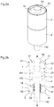
Figure 1a illustrates a conventional vacuum interrupter without external encapsulation. -
Figures 1b and 1c are cross sections of the vacuum interrupter illustrated infigure 1a . -
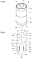
Figure 2a illustrates a vacuum interrupter according to a first embodiment of the invention. -
Figures 2b and2c are cross section of the vacuum interrupter illustrated infigure 2a . -
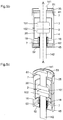
Figures 2d and 2e are enlarged views of a portion of the vacuum interrupter illustrated infigures 2a to 2c . -
Figures 3a and 3b illustrate a vacuum interrupter according to a first variant of the first embodiment of the invention. -
Figures 4a and 4b illustrate a vacuum interrupter according to a second variant of the first embodiment of the invention. -
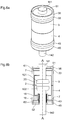
Figure 5a illustrates a vacuum interrupter according to a second embodiment of the invention. -
Figures 5b and 5c are cross section of the vacuum interrupter illustrated infigure 5a . -
Figures 6a and 6b illustrate a vacuum interrupter according to a variant of the second embodiment of the invention. - Although the essential feature of the invention concerns the external design of a vacuum interrupter, such an interrupter will be first briefly described for the sake of clarity and completeness.
- A
vacuum interrupter 1 according to the invention is designed for use in a circuit-breaking device to perform switching and/or breaking in an electric circuit. Thevacuum interrupter 1 according to the invention is preferably arranged to operate at high or medium voltage. - The
vacuum interrupter 1 generally comprises a sealedextinguishing chamber 2 in which a controlled low pressure of air or another dielectric fluid preferably prevails, i.e. a vacuum. Thechamber 2 is defined by a tubular insulating case. In the illustratedvacuum interrupter 1, the tubular insulating case is preferably formed by twoinsulating cylinders - A conducting
cap chamber 2. Preferably, thecaps interrupter 1 and extended on its periphery by an essentiallyorthogonal sidewall - The conducting
caps ceramic cylinders sealing area 7. Thesealing area 7 is limited to a line that corresponds to a braze of theperipheral wall caps ceramic cylinders caps ceramic cylinders - The
chamber 2 bounded by theceramic cylinders caps acting contacts vacuum interrupter 1. Eachcontact contact pad longitudinal electrode - Preferably, as illustrated, a
first contact 101 is stationary and securely fixed to one of theend caps 51 to which itselectrode 141 is coupled, for example by welding, brazing or mechanical assembly. Thesecond contact 102 is mounted inside thechamber 2 with itselectrode 142 so as to be able to move through theother cap 52. To enable themovable contact 102 to move and to maintain the controlled vacuum insidechamber 2, a sealingmetallic bellows 16 is fitted between themovable electrode 142, to which it can for example be welded at one end, and thecorresponding cap 52, thereby sealing the opening of thecap 52 of thechamber 2. Ametallic bellows shield 18 can be fitted around the sealing bellows 16, at the level of the end thereof coupled to theelectrode 142, to protect the said bellows 16 against projections caused by the arc during a current interruption process. - The tightly sealed
chamber 2 preferably further comprises ametallic shield 20 positioned at the level of thecontact pads ceramic cylinders metallic shield 20 is held between the twoceramic cylinders metallic shield 20 could be secured in a fixed manner to one of thecaps - A
vacuum interrupter 1 as described above is pictured for example infigures 1a to 1c . It is well known to the person of ordinary skills in the art and has been described as an example only. The internal components of the interrupter (contacts cylinders interrupter 1. These internal design features are well known to the person of ordinary skills in the art and will not be described in further detail. - Without any further external additional insulation or encapsulation of the vacuum interrupter, an electric breakdown might occur between the
caps contacts - To prevent such dielectric failure, it is known to encapsulate the interrupter in a sealed case containing a dielectric fluid/gas or to coat (embed) all or part of it in a suitable polymer like silicon rubber or epoxy. As previously mentioned, those solutions present some drawbacks.
- According to the invention, the tubular insulating case is extended on its outside part so as to surround and enclose the
caps - Generally, the insulating tubular case of the
vacuum interrupter 1 according to the present invention is designed to surround and enclose thecaps sidewall caps - In a first embodiment illustrated in
figures 2a and 2b , the ceramic cylinders 3', 4' forming the tubular insulating case are each made in one piece so that they each extend beyond theirrespective caps sidewall figure 2b ). In this first embodiment, theextension portions sidewall caps inner flange sealing area 7 and on which thewalls caps extension portions flange caps -
Figure 2d is an enlarged view of thegap 8 between the metal caps 51, 52 and theextension portions figure 2e , thegap 8 between the metal caps 51, 52 and theextension portions resin 9 to supress the sharp corner and reduce the electric field enhancement. Preferably, the said fillingresin 9 is an epoxy-resin or rubber (silicone rubber, polyurethane...) or a suitable semi-conductive resin. More preferably, for a better distribution of the electric potential lines, the said fillingresin 9 is a metal-filled or ceramic- (micro- or nano-powder) filled epoxy (Al2O3-filled epoxy, TiO2-filled epoxy or SiO2-filled epoxy composites, for example). - Preferably, the
angle 81 at the bottom of thegap 8, defined as the angle between theinner flange extension portion figures 2d an 2e. This is to reduce the electric field enhancement. - In the first embodiment illustrated on
figure 2a to 2d , the cylinders 3', 4' present the same external diameter along their length.Figures 3a and 3b illustrate a variant in which the cylinders 3', 4' each present a portion with a larger external diameter forming abulge area 7 and theflanges - In another variant shown in
figures 4a to 4b , theextension portions caps inner flanges sealing areas 7. This specific variant presents the same effect as obtained by thebulge -
Figures 5a to 6b illustrate a second embodiment of a vacuum interrupter according to the invention. This particular embodiment aims to apply the essential principle of the invention to existing standard ceramic or glass-ceramic vacuum interrupters (i.e. such as shown infigures 1a to 1c ). - According to this second embodiment, the tubular insulating case is extended to surround the
caps extension portions cylinders extension portions extension portions respective cylinders 3, 4 (seefigure 5b ) and to wholly surround thecaps sidewalls extension portions respective cylinders e r ∼ 3,5 for epoxy). - Like for the first embodiment, in a variant shown in
figures 6a and 6b , theextension portions bulge area 7 where thecaps cylinders - In a similar fashion, the gap between the metal caps 51, 52 and the
extension portions cylinders - Hence, with this second embodiment, it is possible to outfit prior art vacuum interrupters that would previously have to be encapsulated to ensure external dielectric performances without modifying the existing design of said prior art vacuum interrupters.
- The invention presents the following advantages:
- The external insulation and dielectric performances of the vacuum interrupter are improved without the need to make big changes to its standard well-known design; there is in particular no need to modify the inner dimensions and setting of the vacuum interrupter.
- There is no need to seal the vacuum interrupter in an external encapsulation medium like SF6, oil or pressurised air which leads to cumbersome devices and are not practical for outdoor uses;
- There is no need for whole or partial additional encapsulation with solid insulator like epoxy, silicone rubber or any other suitable polymer that do not age well in harsh atmospheric conditions;
- Ceramic components provide a good insulation and have a good resistance to environmental conditions especially to ozone formation, ensuring a long life of the whole interrupter.
- The above embodiments have been described as examples. Some modifications or variations in the invention are construed to be within the scope of the invention, as defined by the appended claims.
Claims (13)
- Vacuum interrupter (1) comprising a tubular insulating case (3', 4') extending along a longitudinal axis (AA), two conducting caps (51, 52) each securely fixed at an open end of the tubular insulating case (3', 4') at a sealing area (7) to form a tightly sealed chamber (2), characterised in that the tubular insulating case (3', 4') comprises two extension portions (31, 41) made of insulating material and each essentially extending from the sealing area (7) along the longitudinal axis (AA) beyond a corresponding conductive cap (51, 52) to wholly enclose and surround said corresponding conductive cap (51, 52); and in that the extension portions (31, 41) are made in one piece with the tubular insulating case (3', 4').
- Vacuum interrupter (1) according to claim 1, characterised in that the tubular insulating case (3', 4') and the extension portions (31, 41) present on their outside surface a bulge (33, 43) opposite each of the sealing areas (7) where the caps (51, 52) are respectively sealed to the tubular insulating case (3', 4').
- Vacuum interrupter (1) according to claim 1, characterised in that the extension portions (31, 41) are tubular, have essentially the same thickness as the tubular insulating case (3', 4') and have a greater inner and outer diameter than said tubular insulating case, in such a way that a shoulder (33', 43') is formed on the outside of the said tubular insulating case opposite each of the sealing areas (7) where the caps (51, 52) are respectively sealed to the tubular insulating case (3', 4').
- Vacuum interrupter (1) according to any of preceding claims, characterised in that there is a gap (8) between the conductive caps (51, 52) and the extension portions of the tubular insulating case.
- Vacuum interrupter (1) according to claim 4, characterised in that this gap (8) is filled with a filling resin (9).
- Vacuum interrupter (1) according to claim 5, characterised in that said filling resin (9) is either an epoxy-resin or rubber (silicone rubber, polyurethane...) or a semi-conductive resin or ceramic- or metal-filled epoxy resin.
- Vacuum interrupter (1) according to any of the preceding claims, characterised in that the tubular insulating case (3', 4') further comprise each an inner flange (30, 40) which corresponds to the sealing area (7) and on which the walls (61, 62) of the caps 51, 52 are brazed or suitably sealed; and in that the angle (81) between the inner flange (30, 40) and the said walls of the extension portion (31, 41) is rounded.
- Vacuum interrupter (1) according to any of the preceding claims, characterised in that the tubular insulating case is made of ceramic or glass-ceramic.
- Vacuum interrupter (1) according to any of the preceding claims, characterised in that the tubular insulating case is made of two cylinders (3', 4') sealed together to form a tubular case.
- Vacuum interrupter (1) comprising a tubular insulating case (3, 4) extending along a longitudinal axis (AA), two conducting caps (51, 52) each securely fixed at an open end of the tubular insulating case (3, 4) at a sealing area (7) to form a tightly sealed chamber (2), the tubular insulating case (3, 4) being made of ceramic or glass-ceramic, characterised in that it comprises two extension portions (35, 45) made of ceramic or glass-ceramic; in that the two extension portions (35, 45) are securely affixed to the tubular insulating case and overlap part of the said tubular insulating case near the sealing area (7); and in that the two extension portions (35, 45) extend essentially from the sealing area (7) along the longitudinal axis (AA) and each enclose and surround a corresponding conductive cap (51, 52).
- Vacuum interrupter (1) according to claim 10, characterised in that there is a gap (8) between the conductive caps (51, 52) and the extension portions of the tubular insulating case.
- Vacuum interrupter (1) according to claim 11, characterised in that this gap (8) is filled with a filling resin (9).
- Vacuum interrupter (1) according to claim 12, characterised in that said filling resin (9) is either an epoxy-resin or rubber (silicone rubber, polyurethane...) or a semi-conductive resin or ceramic- or metal-filled epoxy resin.
Applications Claiming Priority (2)
| Application Number | Priority Date | Filing Date | Title |
|---|---|---|---|
| EP14160204 | 2014-03-17 | ||
| PCT/IB2015/051809 WO2015140674A1 (en) | 2014-03-17 | 2015-03-12 | Circuit interrupting device |
Publications (2)
| Publication Number | Publication Date |
|---|---|
| EP3120370A1 EP3120370A1 (en) | 2017-01-25 |
| EP3120370B1 true EP3120370B1 (en) | 2019-04-24 |
Family
ID=50277131
Family Applications (1)
| Application Number | Title | Priority Date | Filing Date |
|---|---|---|---|
| EP15714029.4A Active EP3120370B1 (en) | 2014-03-17 | 2015-03-12 | Circuit interrupting device |
Country Status (7)
| Country | Link |
|---|---|
| US (1) | US10074496B2 (en) |
| EP (1) | EP3120370B1 (en) |
| JP (1) | JP2017511568A (en) |
| KR (1) | KR102517402B1 (en) |
| CN (1) | CN106133869B (en) |
| RU (1) | RU2016140649A (en) |
| WO (1) | WO2015140674A1 (en) |
Families Citing this family (5)
| Publication number | Priority date | Publication date | Assignee | Title |
|---|---|---|---|---|
| DE102016218316A1 (en) | 2016-09-23 | 2018-03-29 | Siemens Aktiengesellschaft | vacuum switch |
| CN108321000B (en) * | 2018-04-12 | 2024-01-02 | 大连理工大学 | Vacuum arc-extinguishing chamber for self-equalizing multi-fracture vacuum circuit breaker |
| EP3916750A4 (en) * | 2019-02-06 | 2022-08-24 | Meidensha Corporation | Vacuum interrupter |
| EP3780056A1 (en) * | 2019-08-16 | 2021-02-17 | Siemens Aktiengesellschaft | Ventilating insulating member for interrupter units |
| KR20210026672A (en) * | 2019-08-30 | 2021-03-10 | 캐논 톡키 가부시키가이샤 | Vacuum apparatus |
Family Cites Families (10)
| Publication number | Priority date | Publication date | Assignee | Title |
|---|---|---|---|---|
| DE1790217A1 (en) * | 1968-09-30 | 1972-01-20 | Inst Prueffeld Fuer Elek Sche | Arc extinguishing chamber for vacuum switchgear |
| GB1281938A (en) * | 1969-11-12 | 1972-07-19 | Ass Elect Ind | Improvements relating to vacuum-type circuit-interrupting devices |
| JPS5856444B2 (en) | 1979-12-17 | 1983-12-15 | 株式会社東芝 | vacuum valve |
| DE3628174A1 (en) * | 1986-08-20 | 1988-02-25 | Calor Emag Elektrizitaets Ag | Vacuum switching chamber |
| JP2003031090A (en) | 2001-05-10 | 2003-01-31 | Mitsubishi Electric Corp | Vacuum valve |
| FR2903221B1 (en) * | 2006-06-30 | 2013-12-20 | Schneider Electric Ind Sas | METHOD FOR FASTENING AN ELEMENT IN AN ELECTRICAL APPARATUS AND ELECTRIC APPARATUS SUCH AS A VACUUM BULB HAVING AT LEAST TWO FIXED PARTS ACCORDING TO SUCH A METHOD |
| CN100517540C (en) * | 2007-07-16 | 2009-07-22 | 王雪霖 | A vacuum breaker contact |
| FR2925755B1 (en) | 2007-12-21 | 2012-08-03 | Schneider Electric Ind Sas | INSULATION OF VACUUM BULB TYPE CUTTING DEVICE BY OVERMOLDING |
| DE102008031473B3 (en) | 2008-07-02 | 2010-03-25 | Siemens Aktiengesellschaft | Vacuum interrupter |
| WO2012042294A1 (en) | 2010-10-01 | 2012-04-05 | Abb Technology Ltd | Compact vacuum interrupter with selective encapsulation |
-
2015
- 2015-03-12 EP EP15714029.4A patent/EP3120370B1/en active Active
- 2015-03-12 CN CN201580012511.8A patent/CN106133869B/en active Active
- 2015-03-12 US US15/126,377 patent/US10074496B2/en active Active
- 2015-03-12 WO PCT/IB2015/051809 patent/WO2015140674A1/en active Application Filing
- 2015-03-12 JP JP2016557634A patent/JP2017511568A/en active Pending
- 2015-03-12 RU RU2016140649A patent/RU2016140649A/en not_active Application Discontinuation
- 2015-03-12 KR KR1020167025360A patent/KR102517402B1/en active IP Right Grant
Non-Patent Citations (1)
| Title |
|---|
| None * |
Also Published As
| Publication number | Publication date |
|---|---|
| KR20160133453A (en) | 2016-11-22 |
| EP3120370A1 (en) | 2017-01-25 |
| US10074496B2 (en) | 2018-09-11 |
| KR102517402B1 (en) | 2023-04-03 |
| RU2016140649A (en) | 2018-04-17 |
| US20170084411A1 (en) | 2017-03-23 |
| CN106133869A (en) | 2016-11-16 |
| CN106133869B (en) | 2020-01-17 |
| WO2015140674A1 (en) | 2015-09-24 |
| JP2017511568A (en) | 2017-04-20 |
Similar Documents
| Publication | Publication Date | Title |
|---|---|---|
| US8178812B2 (en) | Insulation of a switchgear device of vacuum cartridge type by insert moulding | |
| EP3120370B1 (en) | Circuit interrupting device | |
| US9214292B2 (en) | Compact vacuum interrupter with selective encapsulation | |
| US8350174B2 (en) | Pole part of a medium-voltage or high-voltage switch gear assembly, and method for its production | |
| CN103594950B (en) | The pole moved end shielding construction of solid insulation switch | |
| KR100789443B1 (en) | Vacuum interrupter for vacuum circuit breaker | |
| CN104103452A (en) | Vacuum chamber with a one-piece metallic cover for self-centering | |
| JP5171298B2 (en) | Resin mold vacuum valve | |
| CN203562686U (en) | Post terminal moving end shielding structure of solid insulation switch | |
| US20150206811A1 (en) | Semiconductor device | |
| CN218996595U (en) | Ceramic vacuum arc-extinguishing chamber with heat shrink tube for circuit breaker | |
| CN219017461U (en) | High-voltage vacuum ceramic capacitor assembly and pole-mounted switch thereof | |
| CN212010840U (en) | Indoor vacuum circuit breaker | |
| WO2018138754A1 (en) | Vacuum valve | |
| KR200309286Y1 (en) | Vacuum interrupter of a vacuum circuit breaker | |
| JP2009048842A (en) | Vacuum switch, and manufacturing method thereof | |
| JP3833444B2 (en) | Mold vacuum valve and manufacturing method thereof | |
| KR101037244B1 (en) | Gas insulated switchgear | |
| KR101783217B1 (en) | Vacuum interrupter with wrap type seal cup | |
| KR101240078B1 (en) | Vacuum interrupter insulation device and method for manufacturing the same | |
| KR20180075916A (en) | Shield device for vacuum interrupter | |
| JP2013183477A (en) | Gas-insulation high voltage apparatus | |
| JP2008027585A (en) | Vacuum switch | |
| JP2009165293A (en) | Shield layer edge trim insulation structure of prefabricated joint |
Legal Events
| Date | Code | Title | Description |
|---|---|---|---|
| STAA | Information on the status of an ep patent application or granted ep patent |
Free format text: STATUS: THE INTERNATIONAL PUBLICATION HAS BEEN MADE |
|
| PUAI | Public reference made under article 153(3) epc to a published international application that has entered the european phase |
Free format text: ORIGINAL CODE: 0009012 |
|
| STAA | Information on the status of an ep patent application or granted ep patent |
Free format text: STATUS: REQUEST FOR EXAMINATION WAS MADE |
|
| 17P | Request for examination filed |
Effective date: 20160815 |
|
| AK | Designated contracting states |
Kind code of ref document: A1 Designated state(s): AL AT BE BG CH CY CZ DE DK EE ES FI FR GB GR HR HU IE IS IT LI LT LU LV MC MK MT NL NO PL PT RO RS SE SI SK SM TR |
|
| AX | Request for extension of the european patent |
Extension state: BA ME |
|
| DAV | Request for validation of the european patent (deleted) | ||
| DAX | Request for extension of the european patent (deleted) | ||
| GRAP | Despatch of communication of intention to grant a patent |
Free format text: ORIGINAL CODE: EPIDOSNIGR1 |
|
| STAA | Information on the status of an ep patent application or granted ep patent |
Free format text: STATUS: GRANT OF PATENT IS INTENDED |
|
| INTG | Intention to grant announced |
Effective date: 20181219 |
|
| GRAS | Grant fee paid |
Free format text: ORIGINAL CODE: EPIDOSNIGR3 |
|
| GRAA | (expected) grant |
Free format text: ORIGINAL CODE: 0009210 |
|
| STAA | Information on the status of an ep patent application or granted ep patent |
Free format text: STATUS: THE PATENT HAS BEEN GRANTED |
|
| AK | Designated contracting states |
Kind code of ref document: B1 Designated state(s): AL AT BE BG CH CY CZ DE DK EE ES FI FR GB GR HR HU IE IS IT LI LT LU LV MC MK MT NL NO PL PT RO RS SE SI SK SM TR |
|
| REG | Reference to a national code |
Ref country code: GB Ref legal event code: FG4D |
|
| REG | Reference to a national code |
Ref country code: CH Ref legal event code: EP |
|
| REG | Reference to a national code |
Ref country code: DE Ref legal event code: R096 Ref document number: 602015028825 Country of ref document: DE |
|
| REG | Reference to a national code |
Ref country code: AT Ref legal event code: REF Ref document number: 1125124 Country of ref document: AT Kind code of ref document: T Effective date: 20190515 Ref country code: IE Ref legal event code: FG4D |
|
| REG | Reference to a national code |
Ref country code: CH Ref legal event code: NV Representative=s name: MICHELI AND CIE SA, CH |
|
| REG | Reference to a national code |
Ref country code: NL Ref legal event code: MP Effective date: 20190424 |
|
| REG | Reference to a national code |
Ref country code: LT Ref legal event code: MG4D |
|
| PG25 | Lapsed in a contracting state [announced via postgrant information from national office to epo] |
Ref country code: NL Free format text: LAPSE BECAUSE OF FAILURE TO SUBMIT A TRANSLATION OF THE DESCRIPTION OR TO PAY THE FEE WITHIN THE PRESCRIBED TIME-LIMIT Effective date: 20190424 |
|
| PG25 | Lapsed in a contracting state [announced via postgrant information from national office to epo] |
Ref country code: ES Free format text: LAPSE BECAUSE OF FAILURE TO SUBMIT A TRANSLATION OF THE DESCRIPTION OR TO PAY THE FEE WITHIN THE PRESCRIBED TIME-LIMIT Effective date: 20190424 Ref country code: SE Free format text: LAPSE BECAUSE OF FAILURE TO SUBMIT A TRANSLATION OF THE DESCRIPTION OR TO PAY THE FEE WITHIN THE PRESCRIBED TIME-LIMIT Effective date: 20190424 Ref country code: PT Free format text: LAPSE BECAUSE OF FAILURE TO SUBMIT A TRANSLATION OF THE DESCRIPTION OR TO PAY THE FEE WITHIN THE PRESCRIBED TIME-LIMIT Effective date: 20190824 Ref country code: AL Free format text: LAPSE BECAUSE OF FAILURE TO SUBMIT A TRANSLATION OF THE DESCRIPTION OR TO PAY THE FEE WITHIN THE PRESCRIBED TIME-LIMIT Effective date: 20190424 Ref country code: NO Free format text: LAPSE BECAUSE OF FAILURE TO SUBMIT A TRANSLATION OF THE DESCRIPTION OR TO PAY THE FEE WITHIN THE PRESCRIBED TIME-LIMIT Effective date: 20190724 Ref country code: FI Free format text: LAPSE BECAUSE OF FAILURE TO SUBMIT A TRANSLATION OF THE DESCRIPTION OR TO PAY THE FEE WITHIN THE PRESCRIBED TIME-LIMIT Effective date: 20190424 Ref country code: HR Free format text: LAPSE BECAUSE OF FAILURE TO SUBMIT A TRANSLATION OF THE DESCRIPTION OR TO PAY THE FEE WITHIN THE PRESCRIBED TIME-LIMIT Effective date: 20190424 Ref country code: LT Free format text: LAPSE BECAUSE OF FAILURE TO SUBMIT A TRANSLATION OF THE DESCRIPTION OR TO PAY THE FEE WITHIN THE PRESCRIBED TIME-LIMIT Effective date: 20190424 |
|
| PG25 | Lapsed in a contracting state [announced via postgrant information from national office to epo] |
Ref country code: RS Free format text: LAPSE BECAUSE OF FAILURE TO SUBMIT A TRANSLATION OF THE DESCRIPTION OR TO PAY THE FEE WITHIN THE PRESCRIBED TIME-LIMIT Effective date: 20190424 Ref country code: PL Free format text: LAPSE BECAUSE OF FAILURE TO SUBMIT A TRANSLATION OF THE DESCRIPTION OR TO PAY THE FEE WITHIN THE PRESCRIBED TIME-LIMIT Effective date: 20190424 Ref country code: GR Free format text: LAPSE BECAUSE OF FAILURE TO SUBMIT A TRANSLATION OF THE DESCRIPTION OR TO PAY THE FEE WITHIN THE PRESCRIBED TIME-LIMIT Effective date: 20190725 Ref country code: BG Free format text: LAPSE BECAUSE OF FAILURE TO SUBMIT A TRANSLATION OF THE DESCRIPTION OR TO PAY THE FEE WITHIN THE PRESCRIBED TIME-LIMIT Effective date: 20190724 Ref country code: LV Free format text: LAPSE BECAUSE OF FAILURE TO SUBMIT A TRANSLATION OF THE DESCRIPTION OR TO PAY THE FEE WITHIN THE PRESCRIBED TIME-LIMIT Effective date: 20190424 |
|
| REG | Reference to a national code |
Ref country code: AT Ref legal event code: MK05 Ref document number: 1125124 Country of ref document: AT Kind code of ref document: T Effective date: 20190424 |
|
| PG25 | Lapsed in a contracting state [announced via postgrant information from national office to epo] |
Ref country code: IS Free format text: LAPSE BECAUSE OF FAILURE TO SUBMIT A TRANSLATION OF THE DESCRIPTION OR TO PAY THE FEE WITHIN THE PRESCRIBED TIME-LIMIT Effective date: 20190824 |
|
| REG | Reference to a national code |
Ref country code: DE Ref legal event code: R097 Ref document number: 602015028825 Country of ref document: DE |
|
| PG25 | Lapsed in a contracting state [announced via postgrant information from national office to epo] |
Ref country code: DK Free format text: LAPSE BECAUSE OF FAILURE TO SUBMIT A TRANSLATION OF THE DESCRIPTION OR TO PAY THE FEE WITHIN THE PRESCRIBED TIME-LIMIT Effective date: 20190424 Ref country code: CZ Free format text: LAPSE BECAUSE OF FAILURE TO SUBMIT A TRANSLATION OF THE DESCRIPTION OR TO PAY THE FEE WITHIN THE PRESCRIBED TIME-LIMIT Effective date: 20190424 Ref country code: EE Free format text: LAPSE BECAUSE OF FAILURE TO SUBMIT A TRANSLATION OF THE DESCRIPTION OR TO PAY THE FEE WITHIN THE PRESCRIBED TIME-LIMIT Effective date: 20190424 Ref country code: AT Free format text: LAPSE BECAUSE OF FAILURE TO SUBMIT A TRANSLATION OF THE DESCRIPTION OR TO PAY THE FEE WITHIN THE PRESCRIBED TIME-LIMIT Effective date: 20190424 Ref country code: RO Free format text: LAPSE BECAUSE OF FAILURE TO SUBMIT A TRANSLATION OF THE DESCRIPTION OR TO PAY THE FEE WITHIN THE PRESCRIBED TIME-LIMIT Effective date: 20190424 Ref country code: SK Free format text: LAPSE BECAUSE OF FAILURE TO SUBMIT A TRANSLATION OF THE DESCRIPTION OR TO PAY THE FEE WITHIN THE PRESCRIBED TIME-LIMIT Effective date: 20190424 |
|
| PG25 | Lapsed in a contracting state [announced via postgrant information from national office to epo] |
Ref country code: SM Free format text: LAPSE BECAUSE OF FAILURE TO SUBMIT A TRANSLATION OF THE DESCRIPTION OR TO PAY THE FEE WITHIN THE PRESCRIBED TIME-LIMIT Effective date: 20190424 Ref country code: IT Free format text: LAPSE BECAUSE OF FAILURE TO SUBMIT A TRANSLATION OF THE DESCRIPTION OR TO PAY THE FEE WITHIN THE PRESCRIBED TIME-LIMIT Effective date: 20190424 |
|
| PLBE | No opposition filed within time limit |
Free format text: ORIGINAL CODE: 0009261 |
|
| STAA | Information on the status of an ep patent application or granted ep patent |
Free format text: STATUS: NO OPPOSITION FILED WITHIN TIME LIMIT |
|
| PG25 | Lapsed in a contracting state [announced via postgrant information from national office to epo] |
Ref country code: TR Free format text: LAPSE BECAUSE OF FAILURE TO SUBMIT A TRANSLATION OF THE DESCRIPTION OR TO PAY THE FEE WITHIN THE PRESCRIBED TIME-LIMIT Effective date: 20190424 |
|
| 26N | No opposition filed |
Effective date: 20200127 |
|
| PG25 | Lapsed in a contracting state [announced via postgrant information from national office to epo] |
Ref country code: SI Free format text: LAPSE BECAUSE OF FAILURE TO SUBMIT A TRANSLATION OF THE DESCRIPTION OR TO PAY THE FEE WITHIN THE PRESCRIBED TIME-LIMIT Effective date: 20190424 |
|
| PG25 | Lapsed in a contracting state [announced via postgrant information from national office to epo] |
Ref country code: MC Free format text: LAPSE BECAUSE OF FAILURE TO SUBMIT A TRANSLATION OF THE DESCRIPTION OR TO PAY THE FEE WITHIN THE PRESCRIBED TIME-LIMIT Effective date: 20190424 |
|
| REG | Reference to a national code |
Ref country code: BE Ref legal event code: MM Effective date: 20200331 |
|
| PG25 | Lapsed in a contracting state [announced via postgrant information from national office to epo] |
Ref country code: LU Free format text: LAPSE BECAUSE OF NON-PAYMENT OF DUE FEES Effective date: 20200312 |
|
| PG25 | Lapsed in a contracting state [announced via postgrant information from national office to epo] |
Ref country code: IE Free format text: LAPSE BECAUSE OF NON-PAYMENT OF DUE FEES Effective date: 20200312 |
|
| PG25 | Lapsed in a contracting state [announced via postgrant information from national office to epo] |
Ref country code: BE Free format text: LAPSE BECAUSE OF NON-PAYMENT OF DUE FEES Effective date: 20200331 |
|
| PG25 | Lapsed in a contracting state [announced via postgrant information from national office to epo] |
Ref country code: MT Free format text: LAPSE BECAUSE OF FAILURE TO SUBMIT A TRANSLATION OF THE DESCRIPTION OR TO PAY THE FEE WITHIN THE PRESCRIBED TIME-LIMIT Effective date: 20190424 Ref country code: CY Free format text: LAPSE BECAUSE OF FAILURE TO SUBMIT A TRANSLATION OF THE DESCRIPTION OR TO PAY THE FEE WITHIN THE PRESCRIBED TIME-LIMIT Effective date: 20190424 |
|
| PG25 | Lapsed in a contracting state [announced via postgrant information from national office to epo] |
Ref country code: MK Free format text: LAPSE BECAUSE OF FAILURE TO SUBMIT A TRANSLATION OF THE DESCRIPTION OR TO PAY THE FEE WITHIN THE PRESCRIBED TIME-LIMIT Effective date: 20190424 |
|
| PGFP | Annual fee paid to national office [announced via postgrant information from national office to epo] |
Ref country code: FR Payment date: 20230324 Year of fee payment: 9 |
|
| PGFP | Annual fee paid to national office [announced via postgrant information from national office to epo] |
Ref country code: GB Payment date: 20230322 Year of fee payment: 9 Ref country code: DE Payment date: 20230321 Year of fee payment: 9 |
|
| PGFP | Annual fee paid to national office [announced via postgrant information from national office to epo] |
Ref country code: CH Payment date: 20230401 Year of fee payment: 9 |