EP3229161A2 - System with a mobile control apparatus and method for issuing a control signal to a component of a medical imaging device - Google Patents
System with a mobile control apparatus and method for issuing a control signal to a component of a medical imaging device Download PDFInfo
- Publication number
- EP3229161A2 EP3229161A2 EP17182993.0A EP17182993A EP3229161A2 EP 3229161 A2 EP3229161 A2 EP 3229161A2 EP 17182993 A EP17182993 A EP 17182993A EP 3229161 A2 EP3229161 A2 EP 3229161A2
- Authority
- EP
- European Patent Office
- Prior art keywords
- control device
- mobile control
- pose
- medical imaging
- unit
- Prior art date
- Legal status (The legal status is an assumption and is not a legal conclusion. Google has not performed a legal analysis and makes no representation as to the accuracy of the status listed.)
- Granted
Links
- 238000002059 diagnostic imaging Methods 0.000 title claims abstract description 109
- 238000000034 method Methods 0.000 title claims description 18
- 238000012546 transfer Methods 0.000 claims description 62
- 238000003032 molecular docking Methods 0.000 claims description 26
- 230000005540 biological transmission Effects 0.000 claims description 18
- 238000001514 detection method Methods 0.000 claims description 10
- 230000008878 coupling Effects 0.000 claims description 3
- 238000010168 coupling process Methods 0.000 claims description 3
- 238000005859 coupling reaction Methods 0.000 claims description 3
- 230000005855 radiation Effects 0.000 description 33
- 238000003384 imaging method Methods 0.000 description 11
- 238000012545 processing Methods 0.000 description 6
- 238000002591 computed tomography Methods 0.000 description 5
- 230000006870 function Effects 0.000 description 5
- 238000005259 measurement Methods 0.000 description 5
- 230000003993 interaction Effects 0.000 description 4
- 238000011835 investigation Methods 0.000 description 4
- 230000005670 electromagnetic radiation Effects 0.000 description 3
- 238000002347 injection Methods 0.000 description 3
- 239000007924 injection Substances 0.000 description 3
- 230000035945 sensitivity Effects 0.000 description 3
- 230000006854 communication Effects 0.000 description 2
- 238000004891 communication Methods 0.000 description 2
- 230000036541 health Effects 0.000 description 2
- 238000002603 single-photon emission computed tomography Methods 0.000 description 2
- 238000003325 tomography Methods 0.000 description 2
- 230000001960 triggered effect Effects 0.000 description 2
- 230000006978 adaptation Effects 0.000 description 1
- 230000000844 anti-bacterial effect Effects 0.000 description 1
- 230000008901 benefit Effects 0.000 description 1
- 230000007175 bidirectional communication Effects 0.000 description 1
- 230000002457 bidirectional effect Effects 0.000 description 1
- 230000001427 coherent effect Effects 0.000 description 1
- 238000004590 computer program Methods 0.000 description 1
- 230000001419 dependent effect Effects 0.000 description 1
- 238000009472 formulation Methods 0.000 description 1
- 238000003780 insertion Methods 0.000 description 1
- 230000037431 insertion Effects 0.000 description 1
- 239000000463 material Substances 0.000 description 1
- 239000000203 mixture Substances 0.000 description 1
- 238000005192 partition Methods 0.000 description 1
- 238000002600 positron emission tomography Methods 0.000 description 1
- 238000003825 pressing Methods 0.000 description 1
- 239000005871 repellent Substances 0.000 description 1
- 239000000243 solution Substances 0.000 description 1
- 230000001225 therapeutic effect Effects 0.000 description 1
- 210000000707 wrist Anatomy 0.000 description 1
Images


Classifications
-
- A—HUMAN NECESSITIES
- A61—MEDICAL OR VETERINARY SCIENCE; HYGIENE
- A61B—DIAGNOSIS; SURGERY; IDENTIFICATION
- A61B6/00—Apparatus for radiation diagnosis, e.g. combined with radiation therapy equipment
- A61B6/04—Positioning of patients; Tiltable beds or the like
-
- A—HUMAN NECESSITIES
- A61—MEDICAL OR VETERINARY SCIENCE; HYGIENE
- A61B—DIAGNOSIS; SURGERY; IDENTIFICATION
- A61B6/00—Apparatus for radiation diagnosis, e.g. combined with radiation therapy equipment
- A61B6/02—Devices for diagnosis sequentially in different planes; Stereoscopic radiation diagnosis
- A61B6/03—Computerised tomographs
-
- A—HUMAN NECESSITIES
- A61—MEDICAL OR VETERINARY SCIENCE; HYGIENE
- A61B—DIAGNOSIS; SURGERY; IDENTIFICATION
- A61B5/00—Measuring for diagnostic purposes; Identification of persons
- A61B5/05—Detecting, measuring or recording for diagnosis by means of electric currents or magnetic fields; Measuring using microwaves or radio waves
- A61B5/055—Detecting, measuring or recording for diagnosis by means of electric currents or magnetic fields; Measuring using microwaves or radio waves involving electronic [EMR] or nuclear [NMR] magnetic resonance, e.g. magnetic resonance imaging
-
- A—HUMAN NECESSITIES
- A61—MEDICAL OR VETERINARY SCIENCE; HYGIENE
- A61B—DIAGNOSIS; SURGERY; IDENTIFICATION
- A61B6/00—Apparatus for radiation diagnosis, e.g. combined with radiation therapy equipment
- A61B6/04—Positioning of patients; Tiltable beds or the like
- A61B6/0407—Supports, e.g. tables or beds, for the body or parts of the body
-
- A—HUMAN NECESSITIES
- A61—MEDICAL OR VETERINARY SCIENCE; HYGIENE
- A61B—DIAGNOSIS; SURGERY; IDENTIFICATION
- A61B6/00—Apparatus for radiation diagnosis, e.g. combined with radiation therapy equipment
- A61B6/46—Apparatus for radiation diagnosis, e.g. combined with radiation therapy equipment with special arrangements for interfacing with the operator or the patient
-
- A—HUMAN NECESSITIES
- A61—MEDICAL OR VETERINARY SCIENCE; HYGIENE
- A61B—DIAGNOSIS; SURGERY; IDENTIFICATION
- A61B6/00—Apparatus for radiation diagnosis, e.g. combined with radiation therapy equipment
- A61B6/54—Control of apparatus or devices for radiation diagnosis
-
- A—HUMAN NECESSITIES
- A61—MEDICAL OR VETERINARY SCIENCE; HYGIENE
- A61B—DIAGNOSIS; SURGERY; IDENTIFICATION
- A61B6/00—Apparatus for radiation diagnosis, e.g. combined with radiation therapy equipment
- A61B6/54—Control of apparatus or devices for radiation diagnosis
- A61B6/548—Remote control of the apparatus or devices
-
- G—PHYSICS
- G05—CONTROLLING; REGULATING
- G05B—CONTROL OR REGULATING SYSTEMS IN GENERAL; FUNCTIONAL ELEMENTS OF SUCH SYSTEMS; MONITORING OR TESTING ARRANGEMENTS FOR SUCH SYSTEMS OR ELEMENTS
- G05B19/00—Programme-control systems
- G05B19/02—Programme-control systems electric
- G05B19/04—Programme control other than numerical control, i.e. in sequence controllers or logic controllers
- G05B19/048—Monitoring; Safety
-
- G—PHYSICS
- G16—INFORMATION AND COMMUNICATION TECHNOLOGY [ICT] SPECIALLY ADAPTED FOR SPECIFIC APPLICATION FIELDS
- G16H—HEALTHCARE INFORMATICS, i.e. INFORMATION AND COMMUNICATION TECHNOLOGY [ICT] SPECIALLY ADAPTED FOR THE HANDLING OR PROCESSING OF MEDICAL OR HEALTHCARE DATA
- G16H30/00—ICT specially adapted for the handling or processing of medical images
- G16H30/20—ICT specially adapted for the handling or processing of medical images for handling medical images, e.g. DICOM, HL7 or PACS
-
- G—PHYSICS
- G16—INFORMATION AND COMMUNICATION TECHNOLOGY [ICT] SPECIALLY ADAPTED FOR SPECIFIC APPLICATION FIELDS
- G16H—HEALTHCARE INFORMATICS, i.e. INFORMATION AND COMMUNICATION TECHNOLOGY [ICT] SPECIALLY ADAPTED FOR THE HANDLING OR PROCESSING OF MEDICAL OR HEALTHCARE DATA
- G16H40/00—ICT specially adapted for the management or administration of healthcare resources or facilities; ICT specially adapted for the management or operation of medical equipment or devices
- G16H40/60—ICT specially adapted for the management or administration of healthcare resources or facilities; ICT specially adapted for the management or operation of medical equipment or devices for the operation of medical equipment or devices
- G16H40/63—ICT specially adapted for the management or administration of healthcare resources or facilities; ICT specially adapted for the management or operation of medical equipment or devices for the operation of medical equipment or devices for local operation
-
- A—HUMAN NECESSITIES
- A61—MEDICAL OR VETERINARY SCIENCE; HYGIENE
- A61B—DIAGNOSIS; SURGERY; IDENTIFICATION
- A61B2560/00—Constructional details of operational features of apparatus; Accessories for medical measuring apparatus
- A61B2560/02—Operational features
-
- G—PHYSICS
- G05—CONTROLLING; REGULATING
- G05B—CONTROL OR REGULATING SYSTEMS IN GENERAL; FUNCTIONAL ELEMENTS OF SUCH SYSTEMS; MONITORING OR TESTING ARRANGEMENTS FOR SUCH SYSTEMS OR ELEMENTS
- G05B2219/00—Program-control systems
- G05B2219/20—Pc systems
- G05B2219/26—Pc applications
- G05B2219/2652—Medical scanner
-
- G—PHYSICS
- G06—COMPUTING; CALCULATING OR COUNTING
- G06F—ELECTRIC DIGITAL DATA PROCESSING
- G06F3/00—Input arrangements for transferring data to be processed into a form capable of being handled by the computer; Output arrangements for transferring data from processing unit to output unit, e.g. interface arrangements
- G06F3/01—Input arrangements or combined input and output arrangements for interaction between user and computer
- G06F3/048—Interaction techniques based on graphical user interfaces [GUI]
- G06F3/0487—Interaction techniques based on graphical user interfaces [GUI] using specific features provided by the input device, e.g. functions controlled by the rotation of a mouse with dual sensing arrangements, or of the nature of the input device, e.g. tap gestures based on pressure sensed by a digitiser
- G06F3/0488—Interaction techniques based on graphical user interfaces [GUI] using specific features provided by the input device, e.g. functions controlled by the rotation of a mouse with dual sensing arrangements, or of the nature of the input device, e.g. tap gestures based on pressure sensed by a digitiser using a touch-screen or digitiser, e.g. input of commands through traced gestures
- G06F3/04883—Interaction techniques based on graphical user interfaces [GUI] using specific features provided by the input device, e.g. functions controlled by the rotation of a mouse with dual sensing arrangements, or of the nature of the input device, e.g. tap gestures based on pressure sensed by a digitiser using a touch-screen or digitiser, e.g. input of commands through traced gestures for inputting data by handwriting, e.g. gesture or text
-
- G—PHYSICS
- G06—COMPUTING; CALCULATING OR COUNTING
- G06F—ELECTRIC DIGITAL DATA PROCESSING
- G06F3/00—Input arrangements for transferring data to be processed into a form capable of being handled by the computer; Output arrangements for transferring data from processing unit to output unit, e.g. interface arrangements
- G06F3/14—Digital output to display device ; Cooperation and interconnection of the display device with other functional units
- G06F3/147—Digital output to display device ; Cooperation and interconnection of the display device with other functional units using display panels
-
- G—PHYSICS
- G06—COMPUTING; CALCULATING OR COUNTING
- G06F—ELECTRIC DIGITAL DATA PROCESSING
- G06F3/00—Input arrangements for transferring data to be processed into a form capable of being handled by the computer; Output arrangements for transferring data from processing unit to output unit, e.g. interface arrangements
- G06F3/16—Sound input; Sound output
- G06F3/167—Audio in a user interface, e.g. using voice commands for navigating, audio feedback
Definitions
- the invention relates to a system comprising a component of a medical imaging device and a mobile control device.
- the invention further relates to a method for outputting a control signal to a component of a medical imaging device.
- the invention further relates to a use of a system for outputting a control signal to a component of a medical imaging device.
- Medical imaging devices particularly medical cutting-imaging devices such as CT and MR devices, typically require the most accurate positioning of the transfer plate on which a patient is supported, relative to the gantry. In many cases, this positioning is done using buttons or other control elements that are fixedly attached directly to the gantry. Depending on the device, these buttons or other controls are located only on the front or both the front and rear of the device. Often, the controls are redundantly located in multiple locations on the gantry, resulting in a negative impact on cost and complexity. Depending on the patient's needs and cultural circumstances, restricting, storing and / or disposing of the patient standing upright next to the patient can be a major limitation.
- the object of the invention is to provide an alternative possibility of controlling a component of a medical imaging device.
- the mobile control device may be designed so that the mobile control device can be carried by a user in one hand and / or on the body and / or that the mobile control device can be operated by a user while the mobile control device is operated by the user in one hand Hand and / or worn on the body.
- the mobile control device can have a first audio interface, which is designed to receive acoustic signals from the user and / or to output them to the user.
- the mobile control device may in particular comprise a plurality of touch-sensitive operating elements, which together form a touch-sensitive surface which is designed to display at least one software operating element and / or to detect at least one touch gesture for actuating at least one software operating element.
- the mobile control device may have a display unit which is designed to display to the user data concerning the medical imaging device and / or the component of the medical imaging device.
- the pose detection unit may be configured to determine whether the pose of the mobile control device exceeds a pose range limit.
- the system may include an alarm signal output unit configured to output an alarm signal such that the alarm signal is output when the pose of the mobile control device exceeds a range-of-range limit.
- system may further comprise a configuration unit configured to configure the mobile control device and / or the control unit based on the Context and / or based on the pose of the mobile control device is formed.
- the component of the medical imaging device may in particular comprise a storage table and a transfer plate, which is arranged relative to the storage table movable on the storage table.
- the system may include the medical imaging device, wherein the medical imaging device comprises a docking unit configured to releasably dock the mobile control device.
- the mechanical connection and / or the docking unit may have a magnetic holder.
- the invention further relates to the use of a system according to one of the aspects disclosed in this specification and / or in the claims for outputting a control signal to a component of a medical imaging device, wherein the outputting of the control signal to the component is effected by means of the control unit by operating the control element.
- the medical imaging device may, for example, be selected from the imaging modality group consisting of an X-ray device, a C-arm X-ray device, a computed tomography device (CT device), a molecular imaging device (MI device), a single-photon emission computed tomography device (SPECT device). Device), a positron emission tomography device (PET device), a magnetic resonance tomography device (MR device) and combinations thereof (in particular PET-CT device, PET-MR device).
- CT device computed tomography device
- MI device molecular imaging device
- SPECT device single-photon emission computed tomography device
- PET device positron emission tomography device
- MR device magnetic resonance tomography device
- the medical imaging device may further comprise a combination of an imaging modality selected, for example, from the imaging modality group and an irradiation modality.
- the irradiation modality can have, for example, an irradiation unit for therapeutic irradiation.
- a computed tomography device is exemplified for a medical imaging device.
- the medical imaging device has an acquisition unit, which is designed to acquire the acquisition data.
- the acquisition unit may comprise a radiation source and a radiation detector.
- the radiation source is designed to emit and / or to excite a radiation, in particular an electromagnetic radiation
- the radiation detector is designed to detect the radiation, in particular the electromagnetic radiation.
- the radiation can, for example, pass from the radiation source to a region to be imaged and / or reach the radiation detector after an interaction with the region to be imaged. In the interaction with the region to be imaged, the radiation is modified and thus the carrier of information concerning the area to be imaged. When the radiation interacts with the detector, this information is captured in the form of acquisition data.
- the acquisition data may be projection data
- the acquisition unit may be a projection data acquisition unit
- the radiation source may be an X-ray source
- the radiation detector may be an X-ray detector.
- the X-ray detector can in particular be a quantum-counting and / or be energy-resolving X-ray detector.
- the acquisition data may be a magnetic resonance data set
- the acquisition unit may be a magnetic resonance data acquisition unit
- the radiation source may be a first radio-frequency antenna unit
- the radiation detector may be the first radio-frequency antenna unit and / or a second radio-frequency antenna unit.
- the component of the medical imaging device may, for example, be a component of a patient positioning device of the medical imaging device and / or a component of a gantry of the medical imaging device.
- one component of the patient support apparatus may be a driver configured to drive movement of the transfer plate relative to the storage table.
- a component of the gantry may be, for example, a laser sight for positioning the patient and / or a radiation source.
- the component can in particular be designed to receive the control signal.
- a control signal may cause movement of the transfer plate.
- a control signal can trigger a radiation.
- the mobile control device may in particular comprise a housing.
- the housing may in particular be designed such that an interior of the mobile control device defined by the housing, in particular limited in all directions, is.
- the system may include a support unit configured to support the mobile control device on the body of a user.
- the support unit may comprise an element selected from the group consisting of a bracelet, a belt, a lanyard, and combinations thereof.
- the support unit may, for example, further comprise a connecting element, which in particular for releasably connecting to the housing and / or is formed with the docking module of the mobile control device.
- the mobile control device can be designed as a wearable, in particular if it has the carrying unit and / or is connected to the carrying unit.
- the system may have another operating state in which the mobile control device and the control unit are not coupled or are not coupled such that actuation of the control element causes the control signal to be output to the component via the control unit.
- the mobile control device and the control unit can be coupled such that an actuation of the operating element causes the output of the control signal to the component by means of the control unit.
- the mobile control device and the control unit may in particular be at least partially coupled by means of hardware and / or at least partially by means of firmware and / or at least partially by means of software.
- the control unit can in particular be integrated in a control device of the medical imaging device and / or arranged on the component of the medical imaging device.
- a context which relates to the medical imaging device and / or a medical examination which can be carried out and / or performed at least partially by the medical imaging device may in particular comprise information indicating a state of the medical imaging device and / or the component of the medical imaging device and / or a state of the investigation, for example steps already taken in the investigation and / or steps of the investigation to be carried out.
- a context concerning a patient support apparatus may include information as to whether or not the transfer plate is inserted into the tunnel-shaped opening.
- a context concerning the investigation may be have information that in the next step of the given workflow, the transfer plate is to be inserted into the tunnel-shaped opening or that in the next step of the given workflow the radiation for the acquisition of acquisition data is to be triggered.
- a pose of the mobile control device may include information concerning a position of the mobile control device and / or an orientation of the mobile control device.
- the pose of the mobile control device may be defined relative to an examination room in which the medical imaging device is installed and / or relative to a component of the medical imaging device.
- a position of the mobile control device may, for example, be understood to be a distance of the mobile control device from a reference location, for example at the gantry.
- the mobile control device and / or the control unit can be configured by means of the configuration unit based on the pose of the mobile control device such that safety-relevant functions can no longer be triggered if the distance to the reference location exceeds a threshold value.
- the determination of the pose can be carried out, for example, based on a triangulation, a field strength measurement or a transit time measurement of a data transmission medium, in particular in the case of IR and / or radio-based data transmission.
- the determination of the pose can be based, for example, on a detection of an electronic resonant circuit and / or circuit by means of an antenna system.
- the determination of the pose can be carried out, for example, based on a determination of the docking unit to which the mobile control device is docked. This possibility can be useful in particular if the medical imaging device and / or the environment of the medical Imaging device a plurality of docking units, which are arranged spatially distributed and whose position information is known to the system has.
- the detachable docking of the mobile control device to the docking unit may for example form a mechanical and / or positive connection of the mobile control device with the docking unit, wherein the connection is in particular so firmly formed that the forces and / or moments when operating the controls on the mobile control device act, be absorbed by the docking unit. In this way, the user can operate the mobile control device, which is docked to the docking unit, with one hand.
- the detachable docking of the mobile control device to the docking unit may, for example, form a power transmission connection and / or a data transmission connection between the mobile control device and the docking unit.
- the mobile control device can be wirelessly charged to the docking unit with electrical energy.
- the solution according to the invention allows the user of a medical imaging device a far-reaching autonomy about how, when and from where he designs his workflow. For example, the user can better adapt the workflow to the needs of the patient. For example, the user can largely independently select and adapt his position and orientation relative to the gantry and / or relative to the patient positioning device during the examination. Further, the user can operate the mobile control device while walking or running, which provides a valuable time advantage especially for emergency situations.
- Controls that are designed as electromechanical switching element also allow a higher level of security, especially with respect to movements of the transfer plate and the triggering of the radiation, as for example Control element embedded in a software application.
- the operating element can be designed in particular as an electromechanical switching element if it has the electromechanical switching element.
- the electromechanical switching element may in particular be a switch, for example a button.
- the actuation of the operating element may in particular comprise an actuation of the electromechanical switching element.
- the actuation of the electromechanical switching element may in particular comprise a mechanical switching operation in which, for example, an electrically conductive connection is made and / or disconnected and / or in which, for example, at least one mechanical and / or geometric parameter of an electronic circuit is changed.
- the mobile control device and the control unit may be coupled such that actuation of the electromechanical switching element causes the control signal to be output to the component by means of the control unit.
- the operating element may in particular comprise the electromechanical switching element and / or a touch-sensitive surface.
- the touch-sensitive surface of the operating element can form part of the touch-sensitive surface.
- the component and / or a function can be assigned to the operating element based on a touch gesture which is detected by means of the touch-sensitive surface of the operating element and / or by means of the touch-sensitive surface.
- an actuation of the operating element and / or an actuation of the electromechanical switching element can cause the output of the control signal to the component by means of the control unit, wherein the control signal relates to the function associated with the operating element.
- a component of a system according to any of the aspects disclosed in this specification and / or in the claims, which is adapted to, a given step of a method according to one of the aspects disclosed in this specification and / or in the claims are to be implemented in the form of hardware configured to perform the given step and / or configured to execute a computer readable instruction such that the hardware is configurable by means of the computer readable instruction to perform the given step.
- the system can have a memory area, for example in the form of a computer-readable medium, in which computer-readable instructions, for example in the form of a computer program, are stored.
- the hardware may be, for example, a memory system, a field-programmable gate array (FPGA) system, an application-specific integrated circuit (ASIC) system, a microcontroller system, a processor system, and combinations thereof.
- the processor system may include, for example, a microprocessor and / or a plurality of cooperating microprocessors.
- the medical imaging device comprises the medical imaging device.
- the use of the term “unit” does not exclude that the item to which the term “unit” refers may have multiple components that are spatially separated from each other.
- ordinal number words first, second, third, etc.
- the use of ordinal number words in the designation of features primarily serves to improve the distinctness of the features which are designated using ordinal number words.
- based on may be understood in the context of the present application, in particular in the sense of the term “using.”
- a formulation that generates (alternatively: determines, determines, etc.) a first feature based on a second feature does not preclude the first feature from being generated (alternatively: determined, determined, etc.) based on a third feature can.
- Fig. 1 shows a mobile control device 3 of a system 1 according to a first embodiment of the invention.
- the mobile control device 3 has a housing 3C.
- the housing 3C is designed such that an interior of the mobile control device 3 is defined by the housing 3C, in particular limited in all directions.
- the housing 3C may be formed, for example, liquid-tight and / or liquid-repellent.
- the housing 3C may be formed, for example, with antibacterial materials and / or be shaped such that cracks, which are disinfected only with great effort, are avoided.
- Each of the operating elements B10, B11, B12, B13, B14, B21, B22, B30, B41, B42 is each formed as an electromechanical switching element on the housing 3C and / or manually operated by a user U1.
- An electromechanical switching element may in particular have a push button and / or a switch.
- the operation of the mobile control device 3 comprises, in particular, the actuation of one or more of the control elements.
- the mobile control device 3 has a haptic button B10, which in each case context-sensitive releases, activates or closes the next step of a given workflow.
- the default workflow can include both hardware actions and software actions. Examples of hardware actions are the loading and / or unloading of the patient positioning device 10 as well as starting a CT scan. Examples of software actions are the sending of the images of a study in a PACS or the execution of the next step in a sequence of consecutive work steps in a software application, which for example on the tablet computer 5 and / or on a Smartphone and / or on the control device 30 is installed.
- the mobile control device 3 has a first transfer operating element B12 and a second transfer operating element B14. Actuation of the second transfer operating member B14 causes the transfer plate 12 to move in a horizontal direction opposite to the horizontal direction in which the transfer plate 12 is moved when the first transfer operating member B12 is operated.
- the assignment of the horizontal directions to the transfer controls B12 and B14 may be based on the pose of the mobile control device 3 relative to the transfer plate 12 and / or relative to the medical imaging device 2 done.
- the mobile control device 3 and / or the control unit 35 may be configurable by means of the configuration unit 7N based on the pose of the mobile control device 3 such that for a first pose of the mobile control device 3, actuation of the first transfer control element B12 insertion of the transfer plate 12 causes the tunnel-shaped opening 9 and / or an actuation of the second transfer control element B14 causes the transfer plate 12 to move away from the tunnel-shaped opening 9, and that for a second pose of the mobile control device 3, an actuation of the first transfer control element B12 causing the transfer plate 12 to move away from the tunnel-shaped opening 9 and / or an actuation of the second transfer operating element B14 causes the transfer plate 12 to be inserted into the tunnel-shaped opening 9.
- the first horizontal direction may point, for example, from the storage table 11 to the tunnel-shaped opening 9.
- moving the transfer plate 12 in the first horizontal direction may include inserting the transfer plate 12 into the tunnel-shaped opening 9.
- the second horizontal direction may, for example, point from the tunnel-shaped opening 9 onto the storage table 11.
- moving the transfer plate 12 in the second horizontal direction may include moving the transfer plate 12 away from the tunnel-shaped opening 9.
- the first pose may be a pose in which the mobile control device 3 is located on the same side with respect to the gantry 20 as the patient positioning device 10 and the mobile control device 3 is oriented such that the first transfer Operating element B12 is closer to the gantry 20 than the second transfer control B14.
- the second pose may be a pose in which the mobile control device 3 is located on the same side with respect to the gantry 20 as the patient positioning device 10 and the mobile control device 3 is oriented such that the second transfer Operating element B14 is closer to the gantry 20 than the first transfer control B12.
- the first pose of the mobile control device 3 may be present, for example, when the first transfer control element B12 is from the perspective of the user U1 to the right of the second transfer control element B14, which faces user U1 of the patient positioning device 10 and the mobile control device 3, and the gantry 20 is to the right hand of the user U1.
- the second pose of the mobile control device 3 may be present, for example, when the first transfer control element B12 from the perspective of the user U1 is located to the right of the second transfer control element B14, the user U1 of the patient support device 10 and the mobile control device 3 faces and the gantry 20 is to the left hand of the user U1.
- the assignment of the horizontal directions for the movement of the transfer plate 12 to the transfer controls B12 and B14 may depend on which side with respect to the transfer plate 12 the user U1 is located.
- this assignment can take place dynamically, for example, in which the pose of the mobile control device 3 is regularly determined at short intervals and the assignment is adjusted based on the pose.
- the assignment determined based on the pose of the mobile control device 3 can be displayed in particular by means of the display unit 3Y. In this way, the user U1 can recognize which of the transfer controls B12 and B14 to operate to move the transfer plate 12 in a predetermined direction.
- each of the operating elements B10, B11, B12, B13, B14 can each be touch-sensitive and / or have a touch-sensitive surface.
- the controls B10, B11, B12, B13, B14 together form a touch-sensitive surface, which is designed for displaying at least one software operating element and / or for detecting at least one touch gesture for actuating at least one software operating element.
- the at least one software operating element can be displayed in particular by means of the display unit 3Y and / or by means of the touch-sensitive screen 5Y.
- the touch-sensitive surface may in particular be composed of the touch-sensitive surfaces of the operating elements.
- the touch-sensitive surface may be contiguous or composed of a plurality of mutually separated partial surfaces.
- the touch-sensitive surface By means of the touch-sensitive surface, in particular, it is possible to navigate over a plurality of software elements, for example to control the component of the medical imaging device 2 and / or to select data which are to be displayed to the user U1.
- the touch-sensitive surface With the aid of the at least one touch gesture, which is detected by means of the touch-sensitive surface, it is possible, in particular, to scroll through a list with data concerning, for example, the patient 13 and / or an imaging protocol and / or an injection protocol. This can be done, in particular, by wiping with the fingers over the touch-sensitive surface, for example upwards and / or downwards.
- the respectively next step of a given workflow for example the medical imaging examination and / or the control of the medical imaging device 2 and / or automatically selected, confirmed or canceled based on the context of a control software.
- This can be done in particular by swiping with the fingers over the touch-sensitive surface, for example to the right and / or to the left. In this way, using the mobile control device 3 software navigation forward and / or backward through the workflow can be realized.
- a medical imaging examination may, in particular, be understood to mean a medical examination which can be carried out and / or performed at least partially by means of the medical imaging device.
- a connection can be provided, with which power supply and data transmission can take place via the same cable.
- the data transmission module 3T may be located wholly or partly in the interior of the mobile control device 3.
- the power supply module 3E may be wholly or partly located in the interior of the mobile control device 3.
- the data processing module 3P may be located wholly or partly in the interior space of the mobile control device 3.
- one or more further components may be located wholly or partly in the interior of the mobile control device 3.
- the mobile control device 3 has a deadman device 3S, which is designed to detect and / or prevent inadvertent actuation of the operating element.
- An unintentional actuation of the operating element can result, for example, from the fact that the user U1 accidentally sets himself on the mobile control device 3.
- the mobile control device 3 has a docking module 3D.
- the docking module 3D can in particular be designed universally such that the mobile control device 3 can dock both by means of the docking module 3D releasably to a docking unit of the medical imaging device 2 and can be connected to the tablet and / or with the support unit.
- the mobile control device 3 has a first audio interface with a microphone A1 and a speaker A2, which is adapted to receive acoustic signals from the user U1 and / or output to the user U1.
- voice commands for controlling the medical imaging device 2 can be determined, for example.
- the voice commands can be determined, for example, by means of software for recognizing and processing speech. This software may for example be installed on the mobile control device 3 and / or on the tablet computer 5 and / or on the control device 30.
- the user U1 can also speak from a greater distance and / or from another room with the patient 13 and / or with other people in the examination room, for example using a second audio interface 40, which at the Gantry 20 may be arranged and / or which may have a speaker and / or a microphone.
- a second audio interface 40 which at the Gantry 20 may be arranged and / or which may have a speaker and / or a microphone.
- the mobile control device 3 has a display unit 3Y, which is designed to display to the user U1 data concerning the medical imaging device 2 and / or the component of the medical imaging device 2 and / or the examination and / or the patient 13.
- the display unit 3Y can be designed, for example, as a 7-segment display and / or as a screen.
- the mobile control device 3 may have a touch-sensitive screen constituting the display unit 3Y and an input unit.
- the display unit 3Y can be integrated in the housing 3C.
- software for controlling the medical imaging device 2 and / or the component of the medical imaging device 2 can be operated by means of the touch-sensitive screen.
- Fig. 2 shows a mobile control device 3 of a system 1 according to a second embodiment of the invention in a first view.
- Fig. 3 shows a mobile control device 3 of a system 1 according to the second embodiment of the invention in a second view.
- the mobile control device 3 can be used together with a tablet computer 5 and / or a smartphone, on which a software application is installed, which is designed to control the medical imaging device 2 and / or the component of the medical imaging device 2.
- the mobile control device 3 can be magnetically docked, for example, to the tablet computer 5 and / or to a smartphone.
- the tablet computer 5 and the mobile control device 3 can be comfortably carried in this way with only one hand.
- the smartphone and the mobile control device 3 can be comfortably carried in this way with only one hand.
- Fig. 4 shows a mobile control device 3 of a system 1 according to a third embodiment of the invention.
- the mobile control device 3 can, for example, have the tablet computer 5 or be permanently connected to a tablet computer 5 to form a coherent control module.
- the control module enables interactions of the user U1 with the medical imaging device 2 both by means of electromechanical switching elements, which may be advantageous in particular for safety-relevant control commands, as well as by means of the software application installed on the tablet computer 5, which are not critical to safety, particularly in the case of more complex applications. may be advantageous.
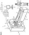
- Fig. 5 1 shows a system 1 according to a fourth embodiment of the invention, comprising the medical imaging device 2.
- a computed tomography device is shown by way of example for the medical imaging device 2.
- the medical imaging device 2 includes the gantry 20, the tunnel-shaped opening 9, the patient support apparatus 10 and the control device 30.
- the gantry 20 has the stationary support frame 21 and the rotor 24.
- the rotor 24 is rotatably arranged by means of a rotary bearing device on a tilting frame about an axis of rotation relative to the stationary support frame 21.
- the acquisition region 4 is located in the tunnel-shaped opening 9.
- a region of the patient 13 to be imaged can be positioned so that the radiation 27 can reach the region to be imaged from the radiation source 26 and, after interacting with the region to be imaged, to the radiation detector 28 can get.
- the patient support apparatus 10 has the storage table 11 and the transfer plate 12 for supporting the patient 13.
- the transfer plate 12 is movably disposed relative to the storage table 11 on the storage table 11 such that the transfer plate 12 is insertable into the acquisition region 4 in a longitudinal direction of the transfer plate 12.
- the medical imaging device 2 is configured to acquire acquisition data based on electromagnetic radiation 27.
- the medical imaging device 2 has an acquisition unit.
- the acquisition unit is a projection data acquisition unit with the radiation source 26, e.g. B. an X-ray source, and the detector 28, z. B. an X-ray detector, in particular an energy-resolving X-ray detector.
- the radiation source 26 is disposed on the rotor 24 and for emitting a radiation 27, z.
- the detector 28 is arranged on the rotor 24 and designed to detect the radiation quanta 27.
- the radiation quanta 27 may be from the radiation source 26 reach the region of the patient to be imaged 13 and impinge on the detector 28 after an interaction with the area to be imaged. In this way, acquisition data of the area to be imaged can be recorded in the form of projection data by means of the acquisition unit.
- the control device 30 is configured to receive the acquisition data acquired by the acquisition unit.
- the control device 30 is configured to control the medical imaging device 2.
- the control unit 35 is integrated in the control device 30.
- the control device 30 is formed by a data processing system having a computer and includes the computer readable medium 32 and the processor system 36.
- the control device 30 has the image reconstruction device 34.
- the image reconstruction device 34 By means of the image reconstruction device 34, based on the acquisition data, a medical image data record can be reconstructed.
- the medical imaging device 2 has an input device 38 and an output device 39, which are each connected to the control device 30.
- the input device 38 is for inputting control information, e.g. B. image reconstruction parameters, examination parameters or the like.
- the output device 39 is designed in particular for outputting control information, images and / or acoustic signals.
- the system 1 has a data transmission unit which is designed to transmit data between the control unit 35 and the mobile control device 3.
- the data may include, for example, acquisition parameters, in particular imaging protocol parameters, injection protocol parameters, Patient parameters, in particular from the electronic health record of the patient 13, and / or measurement data from measurements to support the medical imaging examination, in particular from an ECG measurement include.
- the data transmission unit comprises the data transmission module 3T of the mobile control device 3 and the data transmission module 30T of the control device 30, wherein each of the data transmission modules 3T and 30T is designed to transmit and / or receive the data.
- the data can be transmitted wirelessly and / or wired, for example.
- the data can in particular be transmitted based on a communication protocol that is bidirectional and / or first error-proof.
- the invention enables a wireless secure remote control of the medical imaging device 2 and / or a component of the medical imaging device 2.
- the bidirectional communication protocol allows, for example, in addition to the data concerning the control of the component and which of the mobile control device 3 are transmitted to the control unit 35, further data, which relate for example to the state of one or more components of the medical imaging device 2, can be transmitted to the mobile control device 3.
- released movements of the transfer plate and / or a state of a laser sight for patient positioning by means of the display unit of the mobile control device 3 to the user U1 can be displayed.
- the system 1 further includes the context determination unit 7C, the pose determination unit 7P, and the configuration unit 7N.
- the system 1 comprises a carrying unit W1 with a lanyard. With the aid of the lanyard, the user U1 carries the mobile control device 3 on the body.
- the medical imaging device 2 has a docking unit 20D on the gantry 20 and a docking unit 10D on the patient support apparatus 10. Each of the docking units 20D and 10D is configured to detachably dock the mobile control device 3.
- Fig. 6 shows a system 1 according to a fifth embodiment of the invention, wherein the mobile control device 3 is arranged on the docking unit 10D.
- the mobile control device 3 is connected by means of a cable to the medical imaging device 2, wherein a power supply and / or a data transmission can take place via the cable.
- the system 1 comprises a carrying unit W1 with a wristband.
- the user U1 can carry the mobile control device 3 on the body, in particular on the wrist.
- Fig. 7 shows a system 1 according to a sixth embodiment of the invention, wherein the mobile control device 3 is arranged on the docking unit 20D.
- the system 1 comprises a support unit W1 with a belt. With the help of the belt, the user U1 can carry the mobile control device 3 on the body.
- Fig. 8 a system 1 according to a seventh embodiment of the invention, wherein the system 1 comprises two medical imaging devices.
- the mobile control device 3 may be used in a system 1 having multiple medical imaging devices.
- the medical imaging devices may include different imaging modalities, such as CT and MR devices.
- the mobile control device 3 can be designed to recognize in which room and / or in the vicinity of which of the several medical imaging devices it is located, and / or communicate with the respective medical imaging device, in particular automatically, for example according to "Plug & Play ", connect to.
- the display unit 3Y of the mobile control device 3 it can be displayed with which of the plurality of medical imaging devices and / or with which of the different imaging modalities the mobile control device 3 is connected.
- the system 1 may include a plurality of medical imaging devices and a selection unit configured to select a medical imaging device 2 from the plurality of medical imaging devices based on the context and / or pose of the mobile control assembly.
- the selection unit may for example be integrated in the mobile control device 3 and / or in a data processing system, which may in particular be connected to the mobile control device 3 and / or to the control units of the medical imaging devices by means of a data transmission connection.
- each medical imaging device of the plurality of medical imaging devices may each include a control unit configured to output a control signal to a component of the respective medical imaging device.
- the system 1 may in particular be designed to couple the mobile control device 3 and the control unit of the selected medical imaging device such that actuation of the control element of the mobile control device 3 causes the control signal to be output to the component by means of the control unit.
- the pose detection unit 7P is configured to determine whether the pose of the mobile control device 3 is in a first pose area and / or a second pose area and / or whether the pose of the mobile control device 3 exceeds the pose area boundary P3.
- the first pose region P1A and the second pose region P2A are each dashed shown.
- the first pose area P1B and the second pose area P2B are each shown in dashed lines.
- the first pose area comprises the examination room in which the medical imaging device is installed
- the second pose area comprises the examination room and the control room which is at least partially separated from the examination room by means of a partition wall.
- the seventh embodiment of the invention by operating the corresponding operating element, for example the first transfer operating element or the second transfer operating element, outputting a control signal for moving the transfer plate to the patient support device is effected only when the pose of the mobile control device 3 located in the corresponding first pose area.
- the corresponding operating element for example the first transfer operating element or the second transfer operating element
- first pose areas which are each assigned to a component and / or a control element, can be selected.
- a different first range of poses can be selected, which comprises only the control room, wherein actuation of the corresponding control element only causes output of a control signal for triggering the radiation to the radiation source when the pose of the mobile control unit 3 is in the control room ,
- the mobile control device 3 and the control unit are coupled only when the pose of the mobile control device 3 is in the corresponding second pose area.
- an alarm signal is output by the alarm signal output unit 3A, for example in the form of an alarm tone and / or a vibrating alarm issued.
- the alarm signal output unit 3A for example in the form of an alarm tone and / or a vibrating alarm issued.
- a renewed exceeding of the Posen Schemesgrenze P3 and / or other measures may be required. In this way it can be avoided that the mobile control device 3 is accidentally taken away by a user U1.
Abstract
Die Erfindung betrifft ein System, aufweisend - eine Komponente einer medizinischen Bildgebungsvorrichtung, - ein mobiles Steuerungsgerät mit einem Bedienelement, welches als ein elektromechanisches Schaltelement ausgebildet ist, - eine Steuerungseinheit, welche zum Ausgeben eines Steuersignals an die Komponente ausgebildet ist, - wobei in einem Betriebszustand des Systems das mobile Steuerungsgerät und die Steuerungseinheit derart gekoppelt sind, dass ein Betätigen des Bedienelements das Ausgeben des Steuersignals an die Komponente mittels der Steuerungseinheit bewirkt.The invention relates to a system comprising a component of a medical imaging device, a mobile control device with an operating element which is designed as an electromechanical switching element, a control unit, which is designed to output a control signal to the component, - wherein in an operating state of the system, the mobile control device and the control unit are coupled such that an actuation of the operating element causes the outputting of the control signal to the component by means of the control unit.
Description
Die Erfindung betrifft ein System, aufweisend eine Komponente einer medizinischen Bildgebungsvorrichtung und ein mobiles Steuerungsgerät. Die Erfindung betrifft ferner ein Verfahren zum Ausgeben eines Steuersignals an eine Komponente einer medizinischen Bildgebungsvorrichtung. Die Erfindung betrifft ferner eine Verwendung eines Systems zum Ausgeben eines Steuersignals an eine Komponente einer medizinischen Bildgebungsvorrichtung.The invention relates to a system comprising a component of a medical imaging device and a mobile control device. The invention further relates to a method for outputting a control signal to a component of a medical imaging device. The invention further relates to a use of a system for outputting a control signal to a component of a medical imaging device.
Medizinische Bildgebungsvorrichtungen, insbesondere schnittbildgebende Medizingeräte wie beispielsweise CT-Geräte und MR-Geräte, erfordern typischerweise eine möglichst genaue Positionierung der Transferplatte, auf der ein Patient gelagert ist, relativ zu der Gantry. In vielen Fällen wird diese Positionierung unter Verwendung von Knöpfen oder anderen Kontrollelementen, welche unmittelbar an der Gantry fest angeordnet sind, vorgenommen. Je nach Gerät befinden sich diese Knöpfe oder andere Kontrollelemente ausschließlich an der Vorderseite oder sowohl an der Vorderseite als auch an der Hinterseite des Geräts. Oft sind die Kontrollelemente redundant an mehreren Stellen auf der Gantry verteilt angeordnet, was einen negativen Einfluss in Bezug auf Kosten und Komplexität zur Folge hat. Je nach den Bedürfnissen des Patienten und kulturellen Gegebenheiten kann die Beschränkung, die Lagerung und/oder die Entlagerung des Patienten nur stehend direkt neben dem Patienten durchführen zu können, eine starke Einschränkung darstellen. So wäre es beispielsweise aus Gründen des Zeitgewinns oder auch der Patientensicherheit, insbesondere im Falle eines Notfalls, wünschenswert, die Transferplatte bereits dann bewegen zu können, wenn der Patient und/oder der Nutzer den Untersuchungsraum betritt. Im Falle von kulturellen oder gesundheitlichen Einschränkungen kann es ebenfalls sinnvoll sein die Patientenlagerungsvorrichtung von einer Position aus zu steuern, die weiter von der medizinischen Bildgebungsvorrichtung entfernt ist.Medical imaging devices, particularly medical cutting-imaging devices such as CT and MR devices, typically require the most accurate positioning of the transfer plate on which a patient is supported, relative to the gantry. In many cases, this positioning is done using buttons or other control elements that are fixedly attached directly to the gantry. Depending on the device, these buttons or other controls are located only on the front or both the front and rear of the device. Often, the controls are redundantly located in multiple locations on the gantry, resulting in a negative impact on cost and complexity. Depending on the patient's needs and cultural circumstances, restricting, storing and / or disposing of the patient standing upright next to the patient can be a major limitation. Thus, for reasons of time savings or patient safety, for example, in the case of an emergency, it would be desirable to be able to move the transfer plate already when the patient and / or the user enters the examination room. In case of cultural or health restrictions it can also be useful to control the patient support device from a position that is further away from the medical imaging device.
Die Erfindung hat die Aufgabe, eine alternative Möglichkeit zur Steuerung einer Komponente einer medizinischen Bildgebungsvorrichtung bereitzustellen.The object of the invention is to provide an alternative possibility of controlling a component of a medical imaging device.
Jeder der Gegenstände der unabhängigen Ansprüche löst jeweils diese Aufgabe. In den abhängigen Ansprüchen sind weitere vorteilhafte Aspekte der Erfindung berücksichtigt.Each of the subjects of the independent claims solves this task. In the dependent claims further advantageous aspects of the invention are taken into account.
Die Erfindung betrifft ein System, aufweisend
- eine Komponente einer medizinischen Bildgebungsvorrichtung,
- ein mobiles Steuerungsgerät mit einem Bedienelement, welches als ein elektromechanisches Schaltelement ausgebildet ist,
- eine Steuerungseinheit, welche zum Ausgeben eines Steuersignals an die Komponente ausgebildet ist,
- wobei in einem Betriebszustand des Systems das mobile Steuerungsgerät und die Steuerungseinheit derart gekoppelt sind, dass ein Betätigen des Bedienelements das Ausgeben des Steuersignals an die Komponente mittels der Steuerungseinheit bewirkt.
- a component of a medical imaging device,
- a mobile control device with a control element, which is designed as an electromechanical switching element,
- a control unit configured to output a control signal to the component,
- wherein in an operating state of the system, the mobile control device and the control unit are coupled such that an actuation of the control element causes the output of the control signal to the component by means of the control unit.
Das mobile Steuerungsgerät kann insbesondere derart ausgebildet sein, dass das mobile Steuerungsgerät von einem Nutzer in einer Hand und/oder am Körper getragen werden kann und/oder dass das mobile Steuerungsgerät von einem Nutzer bedient werden kann, während das mobile Steuerungsgerät von dem Nutzer in einer Hand und/oder am Körper getragen wird.In particular, the mobile control device may be designed so that the mobile control device can be carried by a user in one hand and / or on the body and / or that the mobile control device can be operated by a user while the mobile control device is operated by the user in one hand Hand and / or worn on the body.
Das mobile Steuerungsgerät kann insbesondere eine erste Audio-Schnittstelle aufweisen, welche dazu ausgebildet ist, akustische Signale von dem Nutzer zu empfangen und/oder an den Nutzer auszugeben.In particular, the mobile control device can have a first audio interface, which is designed to receive acoustic signals from the user and / or to output them to the user.
Das mobile Steuerungsgerät kann insbesondere mehrere berührungsempfindliche Bedienelemente aufweisen, welche zusammen eine berührungsempfindliche Fläche bilden, welche zum Anzeigen zumindest eines Software-Bedienelements und/oder zum Erfassen zumindest einer Berührungsgeste zum Betätigen zumindest eines Software-Bedienelements ausgebildet ist.The mobile control device may in particular comprise a plurality of touch-sensitive operating elements, which together form a touch-sensitive surface which is designed to display at least one software operating element and / or to detect at least one touch gesture for actuating at least one software operating element.
Das mobile Steuerungsgerät kann insbesondere eine Anzeigeeinheit aufweisen, welche dazu ausgebildet ist, dem Nutzer Daten, welche die medizinische Bildgebungsvorrichtung und/oder die Komponente der medizinischen Bildgebungsvorrichtung betreffen, anzuzeigen.In particular, the mobile control device may have a display unit which is designed to display to the user data concerning the medical imaging device and / or the component of the medical imaging device.
Das System kann insbesondere ferner die folgenden Komponenten aufweisen:
- zumindest eine Kontext-Ermittlungseinheit, welche zum Ermitteln eines Kontexts ausgebildet ist, welcher die medizinische Bildgebungsvorrichtung und/oder eine medizinische Untersuchung, welche mittels der medizinischen Bildgebungsvorrichtung durchführbar und/oder zumindest teilweise durchgeführt ist, betrifft, und/oder
- eine Posen-Ermittlungseinheit, welche zum Ermitteln einer Pose des mobilen Steuerungsgeräts ausgebildet ist.
- at least one context determination unit, which is designed to determine a context which relates to the medical imaging device and / or a medical examination, which is feasible and / or at least partially performed by the medical imaging device, and / or
- a pose detection unit configured to detect a pose of the mobile control device.
Die Posen-Ermittlungseinheit kann insbesondere dazu ausgebildet sein, zu ermitteln, ob die Pose des mobilen Steuerungsgeräts eine Posenbereichsgrenze überschreitet.In particular, the pose detection unit may be configured to determine whether the pose of the mobile control device exceeds a pose range limit.
Das System kann insbesondere eine Alarmsignal-Ausgabeeinheit aufweisen, welche zum Ausgeben eines Alarmsignals derart ausgebildet ist, dass das Alarmsignal ausgegeben wird, wenn die Pose des mobilen Steuerungsgeräts eine Posenbereichsgrenze überschreitet.In particular, the system may include an alarm signal output unit configured to output an alarm signal such that the alarm signal is output when the pose of the mobile control device exceeds a range-of-range limit.
Das System kann insbesondere ferner eine Konfigurationseinheit aufweisen, welche zum Konfigurieren des mobilen Steuerungsgeräts und/oder der Steuerungseinheit basierend auf dem Kontext und/oder basierend auf der Pose des mobilen Steuerungsgeräts ausgebildet ist.In particular, the system may further comprise a configuration unit configured to configure the mobile control device and / or the control unit based on the Context and / or based on the pose of the mobile control device is formed.
Die Komponente der medizinischen Bildgebungsvorrichtung kann insbesondere einen Lagerungstisch und eine Transferplatte aufweisen, welche relativ zu dem Lagerungstisch bewegbar an dem Lagerungstisch angeordnet ist.The component of the medical imaging device may in particular comprise a storage table and a transfer plate, which is arranged relative to the storage table movable on the storage table.
Das mobile Steuerungsgerät kann insbesondere ein erstes Transfer-Bedienelement aufweisen,
- wobei das mobile Steuerungsgerät und/oder die Steuerungseinheit mittels der Konfigurationseinheit derart basierend auf der Pose des mobilen Steuerungsgeräts konfigurierbar ist, dass für zumindest eine erste Pose des mobilen Steuerungsgeräts ein Betätigen des ersten Transfer-Bedienelements ein Bewegen der Transferplatte in eine erste horizontale Richtung bewirkt und
- wherein the mobile control device and / or the control unit is configurable by the configuration unit based on the pose of the mobile control device such that for at least a first pose of the mobile control device operating the first transfer control element causes the transfer plate to move in a first horizontal direction, and
Die Posen-Ermittlungseinheit kann insbesondere dazu ausgebildet sein, zu ermitteln, ob sich die Pose des mobilen Steuerungsgeräts in einem ersten Posenbereich befindet,
- wobei das mobile Steuerungsgerät und/oder die Steuerungseinheit mittels der Konfigurationseinheit derart basierend auf der Pose des mobilen Steuerungsgeräts konfigurierbar ist, dass ein Betätigen des Bedienelements das Ausgeben des Steuersignals an die Komponente mittels der Steuerungseinheit in Abhängigkeit davon bewirkt, ob sich die Pose in dem ersten Posenbereich befindet.
- wherein the mobile control device and / or the control unit is configurable by the configuration unit based on the pose of the mobile control device such that actuation of the control element causes the control signal to be output to the component via the control unit depending on whether the pose is in the first Pose area is located.
Die Posen-Ermittlungseinheit kann insbesondere dazu ausgebildet sein, zu ermitteln, ob sich die Pose des mobilen Steuerungsgeräts in einem zweiten Posenbereich befindet,
- wobei das mobile Steuerungsgerät und/oder die Steuerungseinheit mittels der Konfigurationseinheit derart basierend auf der Pose des mobilen Steuerungsgeräts konfigurierbar ist, dass das mobile Steuerungsgerät und die Steuerungseinheit in Abhängigkeit davon gekoppelt sind, ob sich die Pose in dem zweiten Posenbereich befindet.
- wherein the mobile control device and / or the control unit is configurable by the configuration unit based on the pose of the mobile control device such that the mobile control device and the control unit are coupled depending on whether the pose is in the second pose area.
Das System kann insbesondere einen Tabletcomputer mit einer Software-Applikation, welche zum Steuern der medizinischen Bildgebungsvorrichtung und/oder der Komponente der medizinischen Bildgebungsvorrichtung ausgebildet ist, aufweisen,
- wobei das mobile Steuerungsgerät den Tabletcomputer aufweist und/oder wobei das mobile Steuerungsgerät mit dem Tabletcomputer mittels einer mechanischen Verbindung und/oder mittels einer Datenübertragungsverbindung verbindbar und/oder verbunden ist.
- wherein the mobile control device comprises the tablet computer and / or wherein the mobile control device is connectable and / or connected to the tablet computer by means of a mechanical connection and / or by means of a data transmission connection.
Das System kann insbesondere ein Smartphone mit einer Software-Applikation, welche zum Steuern der medizinischen Bildgebungsvorrichtung und/oder der Komponente der medizinischen Bildgebungsvorrichtung ausgebildet ist, aufweisen,
- wobei das mobile Steuerungsgerät das Smartphone aufweist und/oder wobei das mobile Steuerungsgerät mit dem Smartphone mittels einer mechanischen Verbindung und/oder mittels einer Datenübertragungsverbindung verbindbar und/oder verbunden ist.
- wherein the mobile control device comprises the smartphone and / or wherein the mobile control device is connectable and / or connected to the smartphone by means of a mechanical connection and / or by means of a data transmission connection.
Das System kann insbesondere die medizinische Bildgebungsvorrichtung aufweisen, wobei die medizinische Bildgebungsvorrichtung eine Andockeinheit aufweist, welche zum lösbaren Andocken des mobilen Steuerungsgeräts ausgebildet ist.In particular, the system may include the medical imaging device, wherein the medical imaging device comprises a docking unit configured to releasably dock the mobile control device.
Insbesondere kann die mechanische Verbindung und/oder die Andockeinheit eine magnetische Halterung aufweisen.In particular, the mechanical connection and / or the docking unit may have a magnetic holder.
Die Erfindung betrifft ferner ein Verfahren zum Ausgeben eines Steuersignals an eine Komponente einer medizinischen Bildgebungsvorrichtung, wobei das Verfahren die folgenden Schritte umfasst:
- Koppeln eines mobilen Steuerungsgeräts, welches ein Bedienelement aufweist, welches als ein elektromechanisches Schaltelement ausgebildet ist, und
einer Steuerungseinheit, welche zum Ausgeben eines Steuersignals an die Komponente ausgebildet ist, derart, dass ein Betätigen des Bedienelements das Ausgeben des Steuersignals an die Komponente mittels der Steuerungseinheit bewirkt, - Betätigen des Bedienelements,
- Ausgeben des Steuersignals.
- Coupling a mobile control device having an operating element, which is designed as an electromechanical switching element, and
a control unit configured to output a control signal to the component such that actuation of the control element causes the control signal to be output to the component via the control unit, - Operating the operating element,
- Outputting the control signal.
Das Verfahren kann insbesondere ferner die folgenden Schritte umfassen:
- Ermitteln eines Kontexts, welcher die medizinische Bildgebungsvorrichtung und/oder eine medizinische Untersuchung, welche mittels der medizinischen Bildgebungsvorrichtung durchführbar und/oder zumindest teilweise durchgeführt ist, betrifft, und/oder Ermitteln einer Pose des mobilen Steuerungsgeräts,
- Konfigurieren des mobilen Steuerungsgeräts und/oder der Steuerungseinheit basierend auf dem Kontext und/oder basierend auf der Pose des mobilen Steuerungsgeräts.
- Determining a context which relates to the medical imaging device and / or a medical examination that can be carried out and / or performed at least partially by the medical imaging device, and / or determining a pose of the mobile control device,
- Configure the mobile control device and / or the control unit based on the context and / or based on the pose of the mobile control device.
Die Erfindung betrifft ferner die Verwendung eines Systems nach einem der Aspekte, die in dieser Beschreibung und/oder in den Ansprüchen offenbart sind, zum Ausgeben eines Steuersignals an eine Komponente einer medizinischen Bildgebungsvorrichtung, wobei das Ausgeben des Steuersignals an die Komponente mittels der Steuerungseinheit bewirkt wird, indem das Bedienelement betätigt wird.The invention further relates to the use of a system according to one of the aspects disclosed in this specification and / or in the claims for outputting a control signal to a component of a medical imaging device, wherein the outputting of the control signal to the component is effected by means of the control unit by operating the control element.
Die medizinische Bildgebungsvorrichtung kann beispielsweise aus der Bildgebungsmodalitäten-Gruppe gewählt sein, welche aus einem Röntgengerät, einem C-Bogen-Röntgengerät, einem Computertomographiegerät (CT-Gerät), einem Molekularbildgebungsgerät (MI-Gerät), einem Einzelphotonen-Emissions-Computertomographiegerät (SPECT-Gerät), einem Positronen-Emissions-Tomographiegerät (PET-Gerät), einem Magnetresonanztomographiegerät (MR-Gerät) und Kombinationen daraus (insbesondere PET-CT-Gerät, PET-MR-Gerät) besteht. Die medizinische Bildgebungsvorrichtung kann ferner eine Kombination einer Bildgebungsmodalität, die beispielsweise aus der Bildgebungsmodalitäten-Gruppe gewählt ist, und einer Bestrahlungsmodalität aufweisen. Dabei kann die Bestrahlungsmodalität beispielsweise eine Bestrahlungseinheit zur therapeutischen Bestrahlung aufweisen. Ohne Einschränkung des allgemeinen Erfindungsgedankens wird bei einigen der Ausführungsformen ein Computertomographiegerät beispielhaft für eine medizinische Bildgebungsvorrichtung genannt.The medical imaging device may, for example, be selected from the imaging modality group consisting of an X-ray device, a C-arm X-ray device, a computed tomography device (CT device), a molecular imaging device (MI device), a single-photon emission computed tomography device (SPECT device). Device), a positron emission tomography device (PET device), a magnetic resonance tomography device (MR device) and combinations thereof (in particular PET-CT device, PET-MR device). The medical imaging device may further comprise a combination of an imaging modality selected, for example, from the imaging modality group and an irradiation modality. In this case, the irradiation modality can have, for example, an irradiation unit for therapeutic irradiation. Without limiting the general inventive concept, in some of the embodiments, a computed tomography device is exemplified for a medical imaging device.
Gemäß einer Ausführungsform der Erfindung weist die medizinische Bildgebungsvorrichtung eine Akquisitionseinheit, welche zur Akquisition der Akquisitionsdaten ausgebildet ist, auf. Insbesondere kann die Akquisitionseinheit eine Strahlungsquelle und einen Strahlungsdetektor aufweisen. Eine Ausführungsform der Erfindung sieht vor, dass die Strahlungsquelle zur Emission und/oder zur Anregung einer Strahlung, insbesondere einer elektromagnetischen Strahlung, ausgebildet ist und/oder dass der Strahlungsdetektor zur Detektion der Strahlung, insbesondere der elektromagnetischen Strahlung, ausgebildet ist. Die Strahlung kann beispielsweise von der Strahlungsquelle zu einem abzubildenden Bereich gelangen und/oder nach einer Wechselwirkung mit dem abzubildenden Bereich zu dem Strahlungsdetektor gelangen. Bei der Wechselwirkung mit dem abzubildenden Bereich wird die Strahlung modifiziert und damit zum Träger von Informationen, die den abzubildenden Bereich betreffen. Bei der Wechselwirkung der Strahlung mit dem Detektor werden diese Informationen in Form von Akquisitionsdaten erfasst.According to one embodiment of the invention, the medical imaging device has an acquisition unit, which is designed to acquire the acquisition data. In particular, the acquisition unit may comprise a radiation source and a radiation detector. An embodiment of the invention provides that the radiation source is designed to emit and / or to excite a radiation, in particular an electromagnetic radiation, and / or that the radiation detector is designed to detect the radiation, in particular the electromagnetic radiation. The radiation can, for example, pass from the radiation source to a region to be imaged and / or reach the radiation detector after an interaction with the region to be imaged. In the interaction with the region to be imaged, the radiation is modified and thus the carrier of information concerning the area to be imaged. When the radiation interacts with the detector, this information is captured in the form of acquisition data.
Insbesondere bei einem Computertomographiegerät und bei einem C-Bogen-Röntgengerät können die Akquisitionsdaten Projektionsdaten, die Akquisitionseinheit eine Projektionsdaten-Akquisitionseinheit, die Strahlungsquelle eine Röntgenquelle, der Strahlungsdetektor ein Röntgendetektor sein. Der Röntgendetektor kann insbesondere ein quantenzählender und/oder energieauflösender Röntgendetektor sein. Insbesondere bei einem Magnetresonanztomographiegerät können die Akquisitionsdaten ein Magnetresonanzdatensatz, die Akquisitionseinheit eine Magnetresonanzdaten-Akquisitionseinheit, die Strahlungsquelle eine erste Hochfrequenzantenneneinheit, der Strahlungsdetektor die erste Hochfrequenzantenneneinheit und/oder eine zweite Hochfrequenzantenneneinheit sein.Particularly, in a computed tomography apparatus and a C-arm X-ray apparatus, the acquisition data may be projection data, the acquisition unit may be a projection data acquisition unit, the radiation source may be an X-ray source, and the radiation detector may be an X-ray detector. The X-ray detector can in particular be a quantum-counting and / or be energy-resolving X-ray detector. In particular, in a magnetic resonance tomography device, the acquisition data may be a magnetic resonance data set, the acquisition unit may be a magnetic resonance data acquisition unit, the radiation source may be a first radio-frequency antenna unit, the radiation detector may be the first radio-frequency antenna unit and / or a second radio-frequency antenna unit.
Die Komponente der medizinischen Bildgebungsvorrichtung kann beispielsweise eine Komponente einer Patientenlagerungsvorrichtung der medizinischen Bildgebungsvorrichtung und/oder eine Komponente einer Gantry der medizinischen Bildgebungsvorrichtung sein. Eine Komponente der Patientenlagerungsvorrichtung kann beispielsweise ein Antrieb sein, der zum Antreiben einer Bewegung der Transferplatte relativ zu dem Lagerungstisch ausgebildet ist. Eine Komponente der Gantry kann beispielsweise ein Laservisier zur Positionierung des Patienten sein und/oder eine Strahlungsquelle sein. Die Komponente kann insbesondere dazu ausgebildet sein, das Steuersignal zu empfangen. Bei einer Patientenlagerungsvorrichtung kann ein Steuersignal beispielsweise eine Bewegung der Transferplatte bewirken. Bei einer Strahlungsquelle kann ein Steuersignal beispielsweise ein Auslösen einer Strahlung bewirken.The component of the medical imaging device may, for example, be a component of a patient positioning device of the medical imaging device and / or a component of a gantry of the medical imaging device. For example, one component of the patient support apparatus may be a driver configured to drive movement of the transfer plate relative to the storage table. A component of the gantry may be, for example, a laser sight for positioning the patient and / or a radiation source. The component can in particular be designed to receive the control signal. For example, in a patient support apparatus, a control signal may cause movement of the transfer plate. For example, in the case of a radiation source, a control signal can trigger a radiation.
Das mobile Steuerungsgerät kann insbesondere ein Gehäuse aufweisen. Das Gehäuse kann insbesondere derart ausgebildet sein, dass durch das Gehäuse ein Innenraum des mobilen Steuerungsgeräts definiert, insbesondere in alle Richtungen begrenzt, ist.The mobile control device may in particular comprise a housing. The housing may in particular be designed such that an interior of the mobile control device defined by the housing, in particular limited in all directions, is.
Das System kann beispielsweise eine Trageeinheit aufweisen, welche zum Tragen des mobilen Steuerungsgeräts am Körper eines Nutzers ausgebildet ist. Die Trageeinheit kann beispielsweise ein Element aufweisen, welches aus der Gruppe gewählt ist, welche aus einem Armband, einem Gürtel, einem Lanyard und Kombinationen davon besteht. Die Trageinheit kann beispielsweise ferner ein Verbindungselement aufweisen, welches zum insbesondere lösbaren Verbinden mit dem Gehäuse und/oder mit dem Andockmodul des mobilen Steuerungsgeräts ausgebildet ist. Das mobile Steuerungsgerät kann insbesondere dann, wenn es die Trageeinheit aufweist und/oder mit der Trageeinheit verbunden ist, als ein Wearable ausgebildet sein.For example, the system may include a support unit configured to support the mobile control device on the body of a user. For example, the support unit may comprise an element selected from the group consisting of a bracelet, a belt, a lanyard, and combinations thereof. The support unit may, for example, further comprise a connecting element, which in particular for releasably connecting to the housing and / or is formed with the docking module of the mobile control device. The mobile control device can be designed as a wearable, in particular if it has the carrying unit and / or is connected to the carrying unit.
Das System kann insbesondere einen weiteren Betriebszustand aufweisen, in dem das mobile Steuerungsgerät und die Steuerungseinheit nicht gekoppelt sind oder nicht derart gekoppelt sind, dass ein Betätigen des Bedienelements das Ausgeben des Steuersignals an die Komponente mittels der Steuerungseinheit bewirkt. Insbesondere können in dem weiteren Betriebszustand des Systems das mobile Steuerungsgerät und die Steuerungseinheit derart koppelbar sein, dass ein Betätigen des Bedienelements das Ausgeben des Steuersignals an die Komponente mittels der Steuerungseinheit bewirkt. Das mobile Steuerungsgerät und die Steuerungseinheit können insbesondere zumindest teilweise mittels Hardware und/oder zumindest teilweise mittels Firmware und/oder zumindest teilweise mittels Software gekoppelt sein. Die Steuerungseinheit kann insbesondere in eine Steuerungsvorrichtung der medizinischen Bildgebungsvorrichtung integriert sein und/oder an der Komponente der medizinischen Bildgebungsvorrichtung angeordnet sein.In particular, the system may have another operating state in which the mobile control device and the control unit are not coupled or are not coupled such that actuation of the control element causes the control signal to be output to the component via the control unit. In particular, in the further operating state of the system, the mobile control device and the control unit can be coupled such that an actuation of the operating element causes the output of the control signal to the component by means of the control unit. The mobile control device and the control unit may in particular be at least partially coupled by means of hardware and / or at least partially by means of firmware and / or at least partially by means of software. The control unit can in particular be integrated in a control device of the medical imaging device and / or arranged on the component of the medical imaging device.
Ein Kontext, welcher die medizinische Bildgebungsvorrichtung und/oder eine medizinische Untersuchung, welche mittels der medizinischen Bildgebungsvorrichtung durchführbar und/oder zumindest teilweise durchgeführt ist, betrifft, kann insbesondere eine Information aufweisen, welche einen Zustand der medizinischen Bildgebungsvorrichtung und/oder der Komponente der medizinischen Bildgebungsvorrichtung und/oder einen Stand der Untersuchung, beispielsweise bereits ausgeführte Schritte der Untersuchung und/oder noch auszuführende Schritte der Untersuchung, betrifft.A context which relates to the medical imaging device and / or a medical examination which can be carried out and / or performed at least partially by the medical imaging device may in particular comprise information indicating a state of the medical imaging device and / or the component of the medical imaging device and / or a state of the investigation, for example steps already taken in the investigation and / or steps of the investigation to be carried out.
Ein Kontext, der eine Patientenlagerungsvorrichtung betrifft, kann beispielsweise eine Information aufweisen, ob die Transferplatte in die tunnelförmige Öffnung eingeführt ist oder nicht. Ein Kontext, der die Untersuchung betrifft, kann beispielsweise eine Information aufweisen, dass bei dem nächsten Schritt des vorgegebenen Workflows die Transferplatte in die tunnelförmige Öffnung einzuführen ist oder dass bei dem nächsten Schritt des vorgegebenen Workflows die Strahlung für die Akquisition von Akquisitionsdaten auszulösen ist.For example, a context concerning a patient support apparatus may include information as to whether or not the transfer plate is inserted into the tunnel-shaped opening. For example, a context concerning the investigation may be have information that in the next step of the given workflow, the transfer plate is to be inserted into the tunnel-shaped opening or that in the next step of the given workflow the radiation for the acquisition of acquisition data is to be triggered.
Eine Pose des mobilen Steuerungsgeräts kann insbesondere eine Information aufweisen, welche eine Position des mobilen Steuerungsgeräts und/oder eine Orientierung des mobilen Steuerungsgeräts betrifft. Die Pose des mobilen Steuerungsgeräts kann beispielsweise relativ zu einem Untersuchungsraum, in dem die medizinische Bildgebungsvorrichtung installiert ist, und/oder relativ zu einer Komponente der medizinischen Bildgebungsvorrichtung definiert sein.In particular, a pose of the mobile control device may include information concerning a position of the mobile control device and / or an orientation of the mobile control device. For example, the pose of the mobile control device may be defined relative to an examination room in which the medical imaging device is installed and / or relative to a component of the medical imaging device.
Unter einer Position des mobilen Steuerungsgeräts kann beispielsweise ein Abstand des mobilen Steuerungsgeräts zu einem Referenzort, beispielsweise an der Gantry, verstanden werden. Insbesondere kann das mobile Steuerungsgerät und/oder die Steuerungseinheit mittels der Konfigurationseinheit derart basierend auf der Pose des mobilen Steuerungsgeräts konfigurierbar sein, dass sicherheitsrelevante Funktionen nicht mehr ausgelöst werden können, wenn der Abstand zum Referenzort einen Schwellwert überschreitet. Das Ermitteln der Pose kann beispielsweise basierend auf einer Triangulation, einer Feldstärkemessung oder einer Laufzeitmessung eines Datenübertragungsmediums insbesondere bei einer IR- und/oder funkbasierten Datenübertragung, erfolgen. Insbesondere in Bezug auf die Posenbereichsgrenze kann das Ermitteln der Pose beispielsweise auf einer Detektion eines elektronischen Schwingkreises und/oder Schaltkreises mittels eines Antennensystems basieren.A position of the mobile control device may, for example, be understood to be a distance of the mobile control device from a reference location, for example at the gantry. In particular, the mobile control device and / or the control unit can be configured by means of the configuration unit based on the pose of the mobile control device such that safety-relevant functions can no longer be triggered if the distance to the reference location exceeds a threshold value. The determination of the pose can be carried out, for example, based on a triangulation, a field strength measurement or a transit time measurement of a data transmission medium, in particular in the case of IR and / or radio-based data transmission. In particular with regard to the range limit, the determination of the pose can be based, for example, on a detection of an electronic resonant circuit and / or circuit by means of an antenna system.
Ferner kann das Ermitteln der Pose beispielsweise basierend auf einer Ermittlung der Andockeinheit, an welche das mobile Steuerungsgerät angedockt ist, erfolgen. Diese Möglichkeit kann insbesondere dann sinnvoll sein, wenn die medizinische Bildgebungsvorrichtung und/oder die Umgebung der medizinischen Bildgebungsvorrichtung mehrere Andockeinheiten, die räumlich verteilt angeordnet sind und deren Positionsinformationen dem System bekannt sind, aufweist.Furthermore, the determination of the pose can be carried out, for example, based on a determination of the docking unit to which the mobile control device is docked. This possibility can be useful in particular if the medical imaging device and / or the environment of the medical Imaging device a plurality of docking units, which are arranged spatially distributed and whose position information is known to the system has.
Das lösbare Andocken des mobilen Steuerungsgeräts an die Andockeinheit kann beispielsweise eine mechanische und/oder formschlüssige Verbindung des mobilen Steuerungsgeräts mit der Andockeinheit bilden, wobei die Verbindung insbesondere derart fest ausgebildet ist, dass die Kräfte und/oder Momente, die beim Betätigen der Bedienelemente auf das mobile Steuerungsgerät wirken, von der Andockeinheit aufgenommen werden. Auf diese Weise kann der Nutzer das mobile Steuerungsgerät, welches an die Andockeinheit angedockt ist, einhändig bedienen. Das lösbare Andocken des mobilen Steuerungsgeräts an die Andockeinheit kann beispielsweise eine Energieübertragungsverbindung und/oder eine Datenübertragungsverbindung zwischen dem mobilen Steuerungsgerät und der Andockeinheit bilden. Beispielsweise kann das mobile Steuerungsgerät kabellos an der Andockeinheit mit elektrischer Energie aufgeladen werden.The detachable docking of the mobile control device to the docking unit may for example form a mechanical and / or positive connection of the mobile control device with the docking unit, wherein the connection is in particular so firmly formed that the forces and / or moments when operating the controls on the mobile control device act, be absorbed by the docking unit. In this way, the user can operate the mobile control device, which is docked to the docking unit, with one hand. The detachable docking of the mobile control device to the docking unit may, for example, form a power transmission connection and / or a data transmission connection between the mobile control device and the docking unit. For example, the mobile control device can be wirelessly charged to the docking unit with electrical energy.
Die erfindungsgemäße Lösung ermöglicht dem Nutzer einer medizinischen Bildgebungsvorrichtung eine weitgehende Autonomie darüber, wie, wann und von wo aus er seinen Workflow gestaltet. Damit kann der Nutzer den Workflow beispielsweise besser an die Bedürfnisse des Patienten anpassen. Beispielsweise kann der Nutzer seine Position und Orientierung relativ zu der Gantry und/oder relativ zu der Patientenlagerungsvorrichtung während der Untersuchung weitgehend unabhängig wählen und flexibel anpassen. Ferner kann der Nutzer das mobile Steuerungsgerät bedienen, während er geht oder läuft, was insbesondere für Notfall-Situationen einen wertvollen Zeitvorteil ermöglicht.The solution according to the invention allows the user of a medical imaging device a far-reaching autonomy about how, when and from where he designs his workflow. For example, the user can better adapt the workflow to the needs of the patient. For example, the user can largely independently select and adapt his position and orientation relative to the gantry and / or relative to the patient positioning device during the examination. Further, the user can operate the mobile control device while walking or running, which provides a valuable time advantage especially for emergency situations.
Bedienelemente, die als elektromechanisches Schaltelement ausgebildet sind, ermöglichen zudem ein höheres Maß an Sicherheit, insbesondere in Bezug auf Bewegungen der Transferplatte und der Auslösung der Strahlung, als beispielsweise Bedienelement, die in eine Software-Applikation eingebettet sind.Controls that are designed as electromechanical switching element, also allow a higher level of security, especially with respect to movements of the transfer plate and the triggering of the radiation, as for example Control element embedded in a software application.
Das Bedienelement kann insbesondere dann als elektromechanisches Schaltelement ausgebildet sein, wenn es das elektromechanische Schaltelement aufweist. Das elektromechanische Schaltelement kann insbesondere ein Schalter, beispielsweise ein Taster, sein.The operating element can be designed in particular as an electromechanical switching element if it has the electromechanical switching element. The electromechanical switching element may in particular be a switch, for example a button.
Das Betätigen des Bedienelements kann insbesondere ein Betätigen des elektromechanischen Schaltelements umfassen. Das Betätigen des elektromechanischen Schaltelements kann insbesondere einen mechanischen Schaltvorgang umfassen, bei dem beispielsweise eine elektrisch leitende Verbindung hergestellt und/oder getrennt wird und/oder bei dem beispielsweise zumindest ein mechanischer und/oder geometrischer Parameter eines elektronischen Schaltkreises verändert wird.The actuation of the operating element may in particular comprise an actuation of the electromechanical switching element. The actuation of the electromechanical switching element may in particular comprise a mechanical switching operation in which, for example, an electrically conductive connection is made and / or disconnected and / or in which, for example, at least one mechanical and / or geometric parameter of an electronic circuit is changed.
Insbesondere können in dem Betriebszustand des Systems das mobile Steuerungsgerät und die Steuerungseinheit derart gekoppelt sein, dass ein Betätigen des elektromechanischen Schaltelements das Ausgeben des Steuersignals an die Komponente mittels der Steuerungseinheit bewirkt.In particular, in the operating state of the system, the mobile control device and the control unit may be coupled such that actuation of the electromechanical switching element causes the control signal to be output to the component by means of the control unit.
Das Bedienelement kann insbesondere das elektromechanische Schaltelement und/oder eine berührungsempfindliche Oberfläche aufweisen. Die berührungsempfindliche Oberfläche des Bedienelements kann insbesondere einen Teil der berührungsempfindlichen Fläche bilden.The operating element may in particular comprise the electromechanical switching element and / or a touch-sensitive surface. In particular, the touch-sensitive surface of the operating element can form part of the touch-sensitive surface.
Insbesondere kann dem Bedienelement basierend auf einer Berührungsgeste, welche mittels der berührungsempfindlichen Oberfläche des Bedienelements und/oder mittels der berührungsempfindlichen Fläche erfasst wird, die Komponente und/oder eine Funktion zugeordnet werden. Insbesondere kann ein Betätigen des Bedienelements und/oder ein Betätigen des elektromechanischen Schaltelements das Ausgeben des Steuersignals an die Komponente mittels der Steuerungseinheit bewirken, wobei das Steuersignal die Funktion, die dem Bedienelement zugeordnet ist, betrifft.In particular, the component and / or a function can be assigned to the operating element based on a touch gesture which is detected by means of the touch-sensitive surface of the operating element and / or by means of the touch-sensitive surface. In particular, an actuation of the operating element and / or an actuation of the electromechanical switching element can cause the output of the control signal to the component by means of the control unit, wherein the control signal relates to the function associated with the operating element.
Insbesondere kann eine Komponente eines Systems nach einem der Aspekte, die in dieser Beschreibung und/oder in den Ansprüchen offenbart sind, welche dazu ausgebildet ist, einen gegebenen Schritt eines Verfahrens nach einem der Aspekte, die in dieser Beschreibung und/oder in den Ansprüchen offenbart sind, auszuführen, in Form einer Hardware implementiert sein, welche zum Ausführen des gegebenen Schritts konfiguriert ist und/oder welche zum Ausführen einer computerlesbaren Anweisung derart konfiguriert ist, dass die Hardware mittels der computerlesbaren Anweisung zum Ausführen des gegebenen Schritts konfigurierbar ist. Insbesondere kann das System einen Speicherbereich, beispielsweise in Form eines computerlesbaren Mediums, aufweisen, in welchem computerlesbare Anweisungen, beispielsweise in Form eines Computerprogramms, gespeichert sind.In particular, a component of a system according to any of the aspects disclosed in this specification and / or in the claims, which is adapted to, a given step of a method according to one of the aspects disclosed in this specification and / or in the claims are to be implemented in the form of hardware configured to perform the given step and / or configured to execute a computer readable instruction such that the hardware is configurable by means of the computer readable instruction to perform the given step. In particular, the system can have a memory area, for example in the form of a computer-readable medium, in which computer-readable instructions, for example in the form of a computer program, are stored.
Bei der Hardware kann es sich beispielsweise um ein Speichersystem, ein FPGA-System (Field-programmable gate array), ein ASIC-System (Application-specific integrated circuit), ein Mikrocontroller-System, ein Prozessorsystem und Kombinationen davon handeln. Das Prozessorsystem kann beispielsweise einen Mikroprozessor und/oder mehrere zusammenwirkende Mikroprozessoren aufweisen.The hardware may be, for example, a memory system, a field-programmable gate array (FPGA) system, an application-specific integrated circuit (ASIC) system, a microcontroller system, a processor system, and combinations thereof. The processor system may include, for example, a microprocessor and / or a plurality of cooperating microprocessors.
Im Rahmen der Erfindung können Merkmale, welche in Bezug auf unterschiedliche Ausführungsformen der Erfindung und/oder unterschiedliche Anspruchskategorien (Verfahren, Verwendung, Vorrichtung, System usw.) beschrieben sind, zu weiteren Ausführungsformen der Erfindung kombiniert werden. Beispielsweise kann ein Anspruch, der eine Vorrichtung betrifft, auch mit Merkmalen, die im Zusammenhang mit einem Verfahren beschrieben oder beansprucht sind, weitergebildet werden. Funktionale Merkmale eines Verfahrens können dabei durch entsprechend ausgebildete gegenständliche Komponenten ausgeführt werden. Neben den in dieser Anmeldung ausdrücklich beschriebenen Ausführungsformen der Erfindung sind vielfältige weitere Ausführungsformen der Erfindung denkbar, zu denen der Fachmann gelangen kann, ohne den Bereich der Erfindung zu verlassen, soweit er durch die Ansprüche vorgegeben ist.Within the scope of the invention, features which are described with respect to different embodiments of the invention and / or different categories of claims (method, use, apparatus, system, etc.) may be combined to form further embodiments of the invention. For example, a claim concerning a device may also be developed with features described or claimed in connection with a method. Functional features of a method can be carried out by appropriately designed representational components. In addition to the embodiments explicitly described in this application Various other embodiments of the invention are conceivable, to which the person skilled in the art can reach without departing from the scope of the invention, as far as it is predetermined by the claims.
Die Verwendung der unbestimmten Artikel "ein" bzw. "eine" schließt nicht aus, dass das betroffene Merkmal auch mehrfach vorhanden sein kann. Die Verwendung des Ausdrucks "aufweisen" schließt nicht aus, dass die mittels des Ausdrucks "aufweisen" verknüpften Begriffe identisch sein können. Beispielsweise weist die medizinische Bildgebungsvorrichtung die medizinische Bildgebungsvorrichtung auf. Die Verwendung des Ausdrucks "Einheit" schließt nicht aus, dass der Gegenstand, auf den sich der Ausdruck "Einheit" bezieht, mehrere Komponenten aufweisen kann, die räumlich voneinander separiert sind.The use of the indefinite article "a" or "an" does not rule out that the affected feature may also be present multiple times. The use of the term "comprising" does not exclude that the terms associated with the term "comprising" may be identical. For example, the medical imaging device comprises the medical imaging device. The use of the term "unit" does not exclude that the item to which the term "unit" refers may have multiple components that are spatially separated from each other.
Die Verwendung von Ordnungszahlwörtern (erste, zweite, dritte etc.) in der Bezeichnung von Merkmalen dient im Kontext der vorliegenden Anmeldung vor allem der besseren Unterscheidbarkeit der unter Verwendung von Ordnungszahlwörtern bezeichneten Merkmale. Das Nichtvorhandensein eines Merkmals, welches durch eine Kombination eines gegebenen Ordnungszahlworts und eines Begriffs bezeichnet wird, schließt nicht aus, dass ein Merkmal vorhanden sein kann, welches durch eine Kombination eines dem gegebenen Ordnungszahlwort nachfolgenden Ordnungszahlworts und des Begriffs bezeichnet wird.In the context of the present application, the use of ordinal number words (first, second, third, etc.) in the designation of features primarily serves to improve the distinctness of the features which are designated using ordinal number words. The absence of a feature, which is indicated by a combination of a given ordinal number word and a term, does not preclude the presence of a feature denoted by a combination of an ordinal number word and the term following the given ordinal number word.
Der Ausdruck "basierend auf" kann im Kontext der vorliegenden Anmeldung insbesondere im Sinne des Ausdrucks "unter Verwendung von" verstanden werden. Insbesondere schließt eine Formulierung, der zufolge ein erstes Merkmal basierend auf einem zweiten Merkmal erzeugt (alternativ: ermittelt, bestimmt etc.) wird, nicht aus, dass das erste Merkmal basierend auf einem dritten Merkmal erzeugt (alternativ: ermittelt, bestimmt etc.) werden kann.The term "based on" may be understood in the context of the present application, in particular in the sense of the term "using." In particular, a formulation that generates (alternatively: determines, determines, etc.) a first feature based on a second feature does not preclude the first feature from being generated (alternatively: determined, determined, etc.) based on a third feature can.
Im Folgenden werden ausgewählte Ausführungsformen unter Hinweis auf die beigefügten Figuren erläutert. Die Darstellung in den Figuren ist schematisch, stark vereinfacht und nicht zwingend maßstabsgetreu.Hereinafter, selected embodiments will be explained with reference to the attached figures. The representation in the figures is schematic, greatly simplified and not necessarily true to scale.
Es zeigen:
-
Fig. 1 ein mobiles Steuerungsgerät eines Systems gemäß einer ersten Ausführungsform der Erfindung, -
Fig. 2 ein mobiles Steuerungsgerät eines Systems gemäß einer zweiten Ausführungsform der Erfindung in einer ersten Ansicht, -
Fig. 3 ein mobiles Steuerungsgerät eines Systems gemäß der zweiten Ausführungsform der Erfindung in einer zweiten Ansicht, -
Fig. 4 ein mobiles Steuerungsgerät eines Systems gemäß einer dritten Ausführungsform der Erfindung, -
Fig. 5 ein System gemäß einer vierten Ausführungsform der Erfindung, -
Fig. 6 ein System gemäß einer fünften Ausführungsform der Erfindung, -
Fig. 7 ein System gemäß einer sechsten Ausführungsform der Erfindung, -
Fig. 8 ein System gemäß einer siebenten Ausführungsform der Erfindung, -
Fig. 9 ein Ablaufdiagramm für ein Verfahren zum Ausgeben eines Steuersignals an eine Komponente einer medizinischen Bildgebungsvorrichtung gemäß einer achten Ausführungsform der Erfindung, -
Fig. 10 ein Ablaufdiagramm für ein Verfahren zum Ausgeben eines Steuersignals an eine Komponente einer medizinischen Bildgebungsvorrichtung gemäß einer neunten Ausführungsform der Erfindung.
-
Fig. 1 a mobile control device of a system according to a first embodiment of the invention, -
Fig. 2 a mobile control device of a system according to a second embodiment of the invention in a first view, -
Fig. 3 a mobile control device of a system according to the second embodiment of the invention in a second view, -
Fig. 4 a mobile control device of a system according to a third embodiment of the invention, -
Fig. 5 a system according to a fourth embodiment of the invention, -
Fig. 6 a system according to a fifth embodiment of the invention, -
Fig. 7 a system according to a sixth embodiment of the invention, -
Fig. 8 a system according to a seventh embodiment of the invention, -
Fig. 9 a flowchart for a method for outputting a control signal to a component of a medical imaging device according to an eighth embodiment of the invention, -
Fig. 10 a flowchart for a method for outputting a control signal to a component of a medical An imaging device according to a ninth embodiment of the invention.
Das mobile Steuerungsgerät 3 weist ein Gehäuse 3C auf. Das Gehäuse 3C ist derart ausgebildet, dass durch das Gehäuse 3C ein Innenraum des mobilen Steuerungsgeräts 3 definiert, insbesondere in alle Richtungen begrenzt, ist. Das Gehäuse 3C kann beispielsweise flüssigkeitsdicht und/oder flüssigkeitsabweisend ausgebildet sein. Das Gehäuse 3C kann beispielsweise mit antibakteriellen Materialien ausgebildet sein und/oder derart geformt sein, dass Ritzen, die nur mit großem Aufwand desinfizierbar sind, vermieden sind.The
Jedes der Bedienelemente B10, B11, B12, B13, B14, B21, B22, B30, B41, B42 ist jeweils als ein elektromechanisches Schaltelement an dem Gehäuse 3C ausgebildet und/oder von einem Nutzer U1 manuell betätigbar. Ein elektromechanisches Schaltelement kann insbesondere einen Taster und/oder einen Schalter aufweisen. Das Bedienen des mobilen Steuerungsgeräts 3 umfasst insbesondere das Betätigen eines oder mehrerer der Bedienelemente.Each of the operating elements B10, B11, B12, B13, B14, B21, B22, B30, B41, B42 is each formed as an electromechanical switching element on the
Das mobile Steuerungsgerät 3 weist einen haptischen Button B10 auf, der kontextsensitiv jeweils den nächsten Schritt eines vorgegebenen Workflows freigibt, aktiviert oder abschließt. Der vorgegebene Workflow kann sowohl Hardware-Aktionen als auch Software-Aktionen umfassen. Beispiele für Hardware-Aktionen sind das Laden und/oder das Entladen der Patientenlagerungsvorrichtung 10 sowie das Starten eines CT-Scans. Beispiele für Software-Aktionen sind das Verschicken der Bilder einer Untersuchung in einem PACS oder das Ausführen des jeweils nächsten Schritts in einer Folge konsekutiver Arbeitsschritte in einer Software-Applikation, welche beispielsweise auf dem Tabletcomputer 5 und/oder auf einem Smartphone und/oder auf der Steuerungsvorrichtung 30 installiert ist.The
Ein Betätigen des Bedienelements kann insbesondere bewirken, dass ein Steuersignal an eine Komponente entsprechend der Funktion, die dem Bedienelement zugeordnet ist, ausgegeben wird. Den Bedienelementen und/oder Anzeigeelementen des mobilen Steuerungsgeräts 3 sind insbesondere die folgenden Funktionen zugeordnet:
- B11:
Heben der Transferplatte 12, B13: Senken der Transferplatte 12, B21: Laden und/oder Entladen der Patientenlagerungsvorrichtung 10, B22: Lichtschalter, B30: Not-AusSchalter, B41: Start der Strahlungsexposition, B42: Stopp der Strahlungsexposition, - A11: Empfindlichkeit des Mikrophons A1 erhöhen,
- A12: Empfindlichkeit des Mikrophons A1 reduzieren, A13: Markierung, die dem Nutzer U1 anzeigt, dass in diesem Bereich Bedienelemente und Anzeigeelemente angeordnet sind, die das Mikrophon A1 betreffen, A14: Anzeigen der Empfindlichkeit des Mikrophons A1,
- A21: Lautstärke des Lautsprechers A2 erhöhen, A22: Lautstärke des Lautsprechers A2 reduzieren, A23: Markierung, die dem Nutzer U1 anzeigt, dass in diesem Bereich Bedienelemente und Anzeigeelemente angeordnet sind, die den Lautsprecher A2 betreffen, A24: Anzeigen der Lautstärke des Lautsprechers A2.
- B11: lifting the
transfer plate 12, B13: lowering thetransfer plate 12, B21: loading and / or unloading thepatient support device 10, B22: light switch, B30: emergency stop switch, B41: start the radiation exposure, B42: stop the radiation exposure, - A11: increase sensitivity of microphone A1,
- A12: reducing the sensitivity of the microphone A1, A13: marking indicating to the user U1 that controls and display elements relating to the microphone A1 are arranged in this area, A14: displaying the sensitivity of the microphone A1,
- A21: increase loudspeaker volume A2, A22: reduce loudspeaker volume A2, A23: mark indicating to user U1 that controls and display elements relating to loudspeaker A2 are located in this area, A24: display loudspeaker volume A2 ,
Das mobile Steuerungsgerät 3 weist ein erstes Transfer-Bedienelement B12 und ein zweites Transfer-Bedienelement B14 auf. Ein Betätigen des zweiten Transfer-Bedienelements B14 bewirkt ein Bewegen der Transferplatte 12 in eine horizontale Richtung, welche entgegengesetzt zu der horizontalen Richtung ist, in welche die Transferplatte 12 bewegt wird, wenn das erste Transfer-Bedienelement B12 betätigt wird. Insbesondere kann die Zuordnung der horizontalen Richtungen zu den Transfer-Bedienelementen B12 und B14 basierend auf der Pose des mobilen Steuerungsgeräts 3 relativ zu der Transferplatte 12 und/oder relativ zu der medizinischen Bildgebungsvorrichtung 2 erfolgen.The
Beispielsweise kann das mobile Steuerungsgerät 3 und/oder die Steuerungseinheit 35 mittels der Konfigurationseinheit 7N derart basierend auf der Pose des mobilen Steuerungsgeräts 3 konfigurierbar sein, dass für eine erste Pose des mobilen Steuerungsgeräts 3, ein Betätigen des ersten Transfer-Bedienelements B12 ein Einführen der Transferplatte 12 in die tunnelförmige Öffnung 9 bewirkt und/oder ein Betätigen des zweiten Transfer-Bedienelements B14 ein Bewegen der Transferplatte 12 weg von der tunnelförmige Öffnung 9 bewirkt, und dass für eine zweite Pose des mobilen Steuerungsgeräts 3, ein Betätigen des ersten Transfer-Bedienelements B12 ein Bewegen der Transferplatte 12 weg von der tunnelförmige Öffnung 9 bewirkt und/oder ein Betätigen des zweiten Transfer-Bedienelements B14 ein Einführen der Transferplatte 12 in die tunnelförmige Öffnung 9 bewirkt.For example, the
Die erste horizontale Richtung kann beispielsweise von dem Lagerungstisch 11 auf die tunnelförmige Öffnung 9 zeigen. Das Bewegen der Transferplatte 12 in die erste horizontale Richtung kann insbesondere ein Einführen der Transferplatte 12 in die tunnelförmige Öffnung 9 umfassen. Die zweite horizontale Richtung kann beispielsweise von der tunnelförmigen Öffnung 9 auf den Lagerungstisch 11 zeigen. Das Bewegen der Transferplatte 12 in die zweite horizontale Richtung kann insbesondere ein Bewegen der Transferplatte 12 weg von der tunnelförmigen Öffnung 9 umfassen.The first horizontal direction may point, for example, from the storage table 11 to the tunnel-shaped opening 9. In particular, moving the
Insbesondere kann es sich bei der ersten Pose um eine Pose handeln, bei der sich das mobile Steuerungsgerät 3 in Bezug auf die Gantry 20 auf derselben Seite befindet wie die Patientenlagerungsvorrichtung 10 und bei der das mobile Steuerungsgerät 3 derart orientiert ist, dass sich das erste Transfer-Bedienelement B12 näher an der Gantry 20 befindet als das zweite Transfer-Bedienelement B14.In particular, the first pose may be a pose in which the
Insbesondere kann es sich bei der zweiten Pose um eine Pose handeln, bei der sich das mobile Steuerungsgerät 3 in Bezug auf die Gantry 20 auf derselben Seite befindet wie die Patientenlagerungsvorrichtung 10 und bei der das mobile Steuerungsgerät 3 derart orientiert ist, dass sich das zweite Transfer-Bedienelement B14 näher an der Gantry 20 befindet als das erste Transfer-Bedienelement B12.In particular, the second pose may be a pose in which the
Die erste Pose des mobilen Steuerungsgeräts 3 kann beispielsweise dann vorliegen, wenn sich das erste Transfer-Bedienelement B12 aus der Sicht des Nutzers U1 rechts von dem zweiten Transfer-Bedienelement B14 befindet, der Nutzer U1 der Patientenlagerungsvorrichtung 10 und dem mobilen Steuerungsgerät 3 zugewandt ist und sich die Gantry 20 zur rechten Hand des Nutzers U1 befindet. Die zweite Pose des mobilen Steuerungsgeräts 3 kann beispielsweise dann vorliegen, wenn sich das erste Transfer-Bedienelement B12 aus der Sicht des Nutzers U1 rechts von dem zweiten Transfer-Bedienelement B14 befindet, der Nutzer U1 der Patientenlagerungsvorrichtung 10 und dem mobilen Steuerungsgerät 3 zugewandt ist und sich die Gantry 20 zur linken Hand des Nutzers U1 befindet.The first pose of the
Mit anderen Worten, kann die Zuordnung der horizontalen Richtungen für die Bewegung der Transferplatte 12 zu den Transfer-Bedienelementen B12 und B14 davon abhängen, auf welcher Seite in Bezug auf die Transferplatte 12 sich der Nutzer U1 befindet. Diese Zuordnung kann insbesondere dynamisch erfolgen, beispielsweise in dem die Pose des mobilen Steuerungsgeräts 3 regelmäßig in kurzen Zeitabständen ermittelt wird und die Zuordnung basierend auf der Pose angepasst wird. Die basierend auf der Pose des mobilen Steuerungsgeräts 3 ermittelte Zuordnung kann insbesondere mittels der Anzeigeeinheit 3Y angezeigt werden. Auf diese Weise kann der Nutzer U1 erkennen, welches der Transfer-Bedienelemente B12 und B14 zu betätigen ist, um die Transferplatte 12 in eine vorgegebene Richtung zu bewegen.In other words, the assignment of the horizontal directions for the movement of the
Alternativ oder zusätzlich kann jedes der Bedienelemente B10, B11, B12, B13, B14 jeweils berührungsempfindlich sein und/oder eine berührungsempfindliche Oberfläche aufweisen. Damit können die Bedienelemente B10, B11, B12, B13, B14 zusammen eine berührungsempfindliche Fläche bilden, welche zum Anzeigen zumindest eines Software-Bedienelements und/oder zum Erfassen zumindest einer Berührungsgeste zum Betätigen zumindest eines Software-Bedienelements ausgebildet ist. Das zumindest eine Software-Bedienelement kann insbesondere mittels der Anzeigeeinheit 3Y und/oder mittels des berührungsempfindlichen Bildschirms 5Y angezeigt werden.Alternatively or additionally, each of the operating elements B10, B11, B12, B13, B14 can each be touch-sensitive and / or have a touch-sensitive surface. Thus, the controls B10, B11, B12, B13, B14 together form a touch-sensitive surface, which is designed for displaying at least one software operating element and / or for detecting at least one touch gesture for actuating at least one software operating element. The at least one software operating element can be displayed in particular by means of the
Die berührungsempfindliche Fläche kann insbesondere aus den berührungsempfindlichen Oberflächen der Bedienelemente zusammengesetzt sein. Die berührungsempfindliche Fläche kann zusammenhängend sein oder aus mehreren voneinander separierten Teilflächen zusammengesetzt sein.The touch-sensitive surface may in particular be composed of the touch-sensitive surfaces of the operating elements. The touch-sensitive surface may be contiguous or composed of a plurality of mutually separated partial surfaces.
Mittels der berührungsempfindlichen Fläche kann insbesondere über mehrere Software-Elemente navigiert werden, beispielsweise um die Komponente der medizinischen Bildgebungsvorrichtung 2 zu steuern und/oder Daten, die dem Nutzer U1 angezeigt werden sollen, auszuwählen.By means of the touch-sensitive surface, in particular, it is possible to navigate over a plurality of software elements, for example to control the component of the medical imaging device 2 and / or to select data which are to be displayed to the user U1.
Mit Hilfe der zumindest einen Berührungsgeste, welche mittels der berührungsempfindlichen Fläche erfasst wird, kann insbesondere durch eine Liste mit Daten, welche beispielsweise den Patienten 13 und/oder ein Bildgebungsprotokoll und/oder ein Injektionsprotokoll betreffen, gescrollt werden. Das kann insbesondere durch ein Wischen mit den Fingern über die berührungsempfindliche Fläche, beispielsweise nach oben und/oder nach unten, erfolgen.With the aid of the at least one touch gesture, which is detected by means of the touch-sensitive surface, it is possible, in particular, to scroll through a list with data concerning, for example, the
Mit Hilfe der zumindest einen Berührungsgeste, welche mittels der berührungsempfindlichen Fläche erfasst wird, kann insbesondere der jeweils nächste Schritt eines vorgegebenen Workflows, der beispielsweise die medizinische Bildgebungs-Untersuchung und/oder die Steuerung der medizinischen Bildgebungsvorrichtung 2 betrifft und/oder basierend auf dem Kontext von einer Steuerungssoftware automatisch ausgewählt wird, bestätigt oder storniert werden. Das kann insbesondere durch ein Wischen mit den Fingern über die berührungsempfindliche Fläche, beispielsweise nach rechts und/oder nach links, erfolgen. Auf diese Weise ist mit Hilfe des mobilen Steuerungsgeräts 3 eine Software-Navigation vorwärts und/oder rückwärts durch den Workflow realisierbar.With the aid of the at least one touch gesture, which is detected by means of the touch-sensitive surface, in particular the respectively next step of a given workflow, for example the medical imaging examination and / or the control of the medical imaging device 2 and / or automatically selected, confirmed or canceled based on the context of a control software. This can be done in particular by swiping with the fingers over the touch-sensitive surface, for example to the right and / or to the left. In this way, using the
Unter einer medizinischen Bildgebungs-Untersuchung kann insbesondere eine medizinische Untersuchung verstanden werden, welche mittels der medizinischen Bildgebungsvorrichtung durchführbar und/oder zumindest teilweise durchgeführt ist.A medical imaging examination may, in particular, be understood to mean a medical examination which can be carried out and / or performed at least partially by means of the medical imaging device.
Das mobile Steuerungsgerät 3 weist ferner die folgenden Komponenten auf:
- einen Anschluss C1 zur kabelgebundenen Stromversorgung,
- einen Anschluss C2 zur kabelgebundenen Datenübertragung,
ein Datenübertragungsmodul 3T,ein Energieversorgungsmodul 3E,ein Datenverarbeitungsmodul 3P, welches ein Speichermodul und ein Prozessormodul aufweist, und- eine Alarmsignal-
Ausgabeeinheit 3A.
- a connection C1 to the wired power supply,
- a connection C2 for wired data transmission,
- a
data transmission module 3T, - a
power supply module 3E, - a
data processing module 3P having a memory module and a processor module, and - an alarm
signal output unit 3A.
Statt der separaten Anschlüsse C1 und C2 kann beispielsweise ein Anschluss vorgesehen sein, mit dem Stromversorgung und Datenübertragung über dasselbe Kabel erfolgen können.Instead of the separate terminals C1 and C2, for example, a connection can be provided, with which power supply and data transmission can take place via the same cable.
Insbesondere kann sich das Datenübertragungsmodul 3T ganz oder teilweise in dem Innenraum des mobilen Steuerungsgeräts 3 befinden. Insbesondere kann sich das Energieversorgungsmodul 3E ganz oder teilweise in dem Innenraum des mobilen Steuerungsgeräts 3 befinden. Insbesondere kann sich das Datenverarbeitungsmodul 3P ganz oder teilweise in dem Innenraum des mobilen Steuerungsgeräts 3 befinden. Insbesondere können sich eine oder mehrere weitere Komponenten ganz oder teilweise in dem Innenraum des mobilen Steuerungsgeräts 3 befinden.In particular, the
Das mobile Steuerungsgerät 3 weist eine Totmanneinrichtung 3S auf, welche dazu ausgebildet ist, ein unbeabsichtigtes Betätigen des Bedienelements zu erkennen und/oder zu verhindern. Ein unbeabsichtigtes Betätigen des Bedienelements kann sich beispielsweise daraus ergeben, dass sich der Nutzer U1 versehentlich auf das mobile Steuerungsgerät 3 setzt.The
Das mobile Steuerungsgerät 3 weist ein Andockmodul 3D auf. Das Andockmodul 3D kann insbesondere derart universell ausgebildet sein, dass das mobile Steuerungsgerät 3 mittels des Andockmoduls 3D sowohl lösbar an eine Andockeinheit der medizinischen Bildgebungsvorrichtung 2 andocken kann als auch mit dem Tablet und/oder mit der Trageeinheit verbunden werden kann.The
Das mobile Steuerungsgerät 3 weist eine erste Audio-Schnittstelle mit einem Mikrophon A1 und einem Lautsprechen A2 auf, welche dazu ausgebildet ist, akustische Signale von dem Nutzer U1 zu empfangen und/oder an den Nutzer U1 auszugeben.The
Basierend auf den akustischen Signalen, die mittels der ersten Audio-Schnittstelle von dem Nutzer U1 empfangen werden, können beispielsweise Sprachbefehle zur Steuerung der medizinischen Bildgebungsvorrichtung 2 ermittelt werden. Die Sprachbefehle können beispielsweise mittels einer Software zur Erkennung und Verarbeitung von Sprache ermittelt werden. Diese Software kann beispielsweise auf dem mobilen Steuerungsgerät 3 und/oder auf dem Tabletcomputer 5 und/oder auf der Steuerungsvorrichtung 30 installiert sein.Based on the acoustic signals received by the user U1 via the first audio interface, voice commands for controlling the medical imaging device 2 can be determined, for example. The voice commands can be determined, for example, by means of software for recognizing and processing speech. This software may for example be installed on the
Mit Hilfe der ersten Audio-Schnittstelle kann der Nutzer U1 auch aus größerer Entfernung und/oder aus einem anderen Raum mit dem Patienten 13 und/oder mit anderen Personen in dem Untersuchungsraum sprechen, beispielsweise unter Verwendung einer zweiten Audio-Schnittstelle 40, welche an der Gantry 20 angeordnet sein kann und/oder welche einen Lautsprecher und/oder ein Mikrophon aufweisen kann.With the help of the first audio interface, the user U1 can also speak from a greater distance and / or from another room with the
Das mobile Steuerungsgerät 3 weist eine Anzeigeeinheit 3Y auf, welche dazu ausgebildet ist, dem Nutzer U1 Daten, welche die medizinische Bildgebungsvorrichtung 2 und/oder die Komponente der medizinischen Bildgebungsvorrichtung 2 und/oder die Untersuchung und/oder den Patienten 13 betreffen, anzuzeigen. Die Anzeigeeinheit 3Y kann beispielsweise als 7-Segmentanzeige und/oder als Bildschirm ausgebildet sein. Das mobile Steuerungsgerät 3 kann beispielsweise einen berührungsempfindlichen Bildschirm aufweisen, welcher die Anzeigeeinheit 3Y und eine Eingabeeinheit bildet. Insbesondere kann die Anzeigeeinheit 3Y in das Gehäuse 3C integriert sein. Mittels des berührungsempfindlichen Bildschirms kann beispielsweise eine Software zur Steuerung der medizinischen Bildgebungsvorrichtung 2 und/oder der Komponente der medizinischen Bildgebungsvorrichtung 2 bedient werden.The
Das mobile Steuerungsgerät 3 kann zusammen mit einem Tabletcomputer 5 und/oder einem Smartphone verwendet werden, auf dem eine Software-Applikation installiert ist, welche zum Steuern der medizinischen Bildgebungsvorrichtung 2 und/oder der Komponente der medizinischen Bildgebungsvorrichtung 2 ausgebildet ist.The
Der Tabletcomputer 5 weist den berührungsempfindlichen Bildschirm 5Y auf. Mit Hilfe des Tabletcomputers können insbesondere eine oder mehrere der folgenden Schritte des Workflows einer medizinischen Bildgebungs-Untersuchung ausgeführt werden:
Registrierung des Patienten 13,- Anpassen von Untersuchungsparametern, beispielsweise des Bildgebungsprotokolls und/oder des Injektionsprotokolls,
- Bildverarbeitung und/oder Finalisierung von medizinischen Bilddatensätzen,
- Nutzung weiterer Radiologie-Software, insbesondere im Zusammenhang mit PACS, RIS, HIS,
- Kommunikation mit anderen Nutzern, insbesondere mit Mitarbeitern anderer Klinikabteilungen, beispielsweise Radiologe, Empfang, Notaufnahme oder ähnliches.
- Registration of the
patient 13, - Adaptation of examination parameters, for example the imaging protocol and / or the injection protocol,
- Image processing and / or finalization of medical image datasets,
- Use of other radiology software, especially in connection with PACS, RIS, HIS,
- Communication with other users, in particular with employees of other hospital departments, for example radiologist, reception, emergency room or similar.
Das mobile Steuerungsgerät 3 kann beispielsweise magnetisch an den Tabletcomputer 5 und/oder an ein Smartphone angedockt werden. Der Tabletcomputer 5 und das mobile Steuerungsgerät 3 können auf diese Weise bequem mit nur einer Hand getragen werden. Das Smartphone und das mobile Steuerungsgerät 3 können auf diese Weise bequem mit nur einer Hand getragen werden.The
Das mobile Steuerungsgerät 3 kann beispielsweise den Tabletcomputer 5 aufweisen oder fest mit einem Tabletcomputer 5 zu einer zusammenhängenden Steuerungsbaugruppe verbunden werden. Die Steuerungsbaugruppe ermöglicht Interaktionen des Nutzers U1 mit der medizinischen Bildgebungsvorrichtung 2 sowohl mittels elektromechanischer Schaltelemente, welche insbesondere für sicherheitsrelevante Steuerungsbefehle vorteilhaft sein können, als auch mittels der auf dem Tabletcomputer 5 installierten Software-Applikation, welche insbesondere bei komplexeren Anwendungen, die nicht sicherheitskritisch sind, vorteilhaft sein kann.The
Ohne Beschränkung des allgemeinen Erfindungsgedankens ist für die medizinische Bildgebungsvorrichtung 2 beispielhaft ein Computertomographiegerät gezeigt. Die medizinische Bildgebungsvorrichtung 2 weist die Gantry 20, die tunnelförmige Öffnung 9, die Patientenlagerungsvorrichtung 10 und die Steuerungsvorrichtung 30 auf.Without limiting the general inventive concept, a computed tomography device is shown by way of example for the medical imaging device 2. The medical imaging device 2 includes the
Die Gantry 20 weist den stationären Tragrahmen 21 und den Rotor 24 auf. Der Rotor 24 ist mittels einer Drehlagerungsvorrichtung an einem Kipprahmen um eine Rotationsachse relativ zu dem stationären Tragrahmen 21 drehbar angeordnet.The
In die tunnelförmige Öffnung 9 ist der Patient 13 einführbar. In der tunnelförmigen Öffnung 9 befindet sich der Akquisitionsbereich 4. In dem Akquisitionsbereich 4 ist ein abzubildender Bereich des Patienten 13 derart positionierbar, dass die Strahlung 27 von der Strahlungsquelle 26 zu dem abzubildenden Bereich gelangen kann und nach einer Wechselwirkung mit dem abzubildenden Bereich zu dem Strahlungsdetektor 28 gelangen kann.In the tunnel-shaped opening 9 of the
Die Patientenlagerungsvorrichtung 10 weist den Lagerungstisch 11 und die Transferplatte 12 zur Lagerung des Patienten 13 auf. Die Transferplatte 12 ist derart relativ zu dem Lagerungstisch 11 bewegbar an dem Lagerungstisch 11 angeordnet, dass die Transferplatte 12 in einer Längsrichtung der Transferplatte 12 in den Akquisitionsbereich 4 einführbar ist.The
Die medizinische Bildgebungsvorrichtung 2 ist zur Akquisition von Akquisitionsdaten basierend auf einer elektromagnetischen Strahlung 27 ausgebildet. Die medizinische Bildgebungsvorrichtung 2 weist eine Akquisitionseinheit auf. Die Akquisitionseinheit ist eine Projektionsdaten-Akquisitionseinheit mit der Strahlungsquelle 26, z. B. einer Röntgenquelle, und dem Detektor 28, z. B. einem Röntgendetektor, insbesondere einem energieauflösenden Röntgendetektor. Die Strahlungsquelle 26 ist an dem Rotor 24 angeordnet und zur Emission einer Strahlung 27, z. B. einer Röntgenstrahlung, mit Strahlungsquanten 27 ausgebildet. Der Detektor 28 ist an dem Rotor 24 angeordnet und zur Detektion der Strahlungsquanten 27 ausgebildet. Die Strahlungsquanten 27 können von der Strahlungsquelle 26 zu dem abzubildenden Bereich des Patienten 13 gelangen und nach einer Wechselwirkung mit dem abzubildenden Bereich auf den Detektor 28 auftreffen. Auf diese Weise können mittels der Akquisitionseinheit Akquisitionsdaten des abzubildenden Bereichs in Form von Projektionsdaten erfasst werden.The medical imaging device 2 is configured to acquire acquisition data based on electromagnetic radiation 27. The medical imaging device 2 has an acquisition unit. The acquisition unit is a projection data acquisition unit with the
Die Steuerungsvorrichtung 30 ist zum Empfangen der von der Akquisitionseinheit akquirierten Akquisitionsdaten ausgebildet. Die Steuerungsvorrichtung 30 ist zum Steuern der medizinischen Bildgebungsvorrichtung 2 ausgebildet. Gemäß der vierten Ausführungsform der Erfindung ist die Steuerungseinheit 35 in die Steuerungsvorrichtung 30 integriert.The
Die Steuerungsvorrichtung 30 wird von einem Datenverarbeitungssystem, welches einen Computer aufweist, gebildet und weist das computerlesbare Medium 32 und das Prozessorsystem 36 auf.The
Die Steuerungsvorrichtung 30 weist die Bildrekonstruktionseinrichtung 34 auf. Mittels der Bildrekonstruktionseinrichtung 34 kann basierend auf den Akquisitionsdaten ein medizinischer Bilddatensatz rekonstruiert werden.The
Die medizinische Bildgebungsvorrichtung 2 weist eine Eingabevorrichtung 38 und eine Ausgabevorrichtung 39 auf, welche jeweils mit der Steuerungsvorrichtung 30 verbunden sind. Die Eingabevorrichtung 38 ist zum Eingeben von Steuerungs-Informationen, z. B. Bildrekonstruktionsparametern, Untersuchungsparametern oder ähnliches, ausgebildet. Die Ausgabevorrichtung 39 ist insbesondere zum Ausgeben von Steuerungs-Informationen, Bildern und/oder akustischen Signalen ausgebildet.The medical imaging device 2 has an
Das System 1 weist eine Datenübertragungseinheit auf, welche zum Übertragen von Daten zwischen der Steuerungseinheit 35 und dem mobilen Steuerungsgerät 3 ausgebildet ist. Die Daten können beispielsweise Akquisitionsparameter, insbesondere Bildgebungsprotokoll-Parameter, Injektionsprotokollparameter, Patientenparameter, insbesondere aus der elektronischen Gesundheitsakte des Patienten 13, und/oder Messdaten aus Messungen zur Unterstützung der medizinischen Bildgebungs-Untersuchung, insbesondere aus einer EKG-Messung, umfassen. Die Datenübertragungseinheit weist das Datenübertragungsmodul 3T des mobilen Steuerungsgeräts 3 und das Datenübertragungsmodul 30T der Steuerungsvorrichtung 30 auf, wobei jedes der Datenübertragungsmodule 3T und 30T jeweils zum Senden und/oder Empfangen der Daten ausgebildet ist. Die Daten können beispielsweise kabellos und/oder kabelgebunden übertragen werden. Die Daten können insbesondere basierend auf einem Kommunikationsprotokoll übertragen werden, welches bidirektional und/oder erstfehlersicher ist.The system 1 has a data transmission unit which is designed to transmit data between the
Auf diese Weise ermöglicht die Erfindung eine kabellose sichere Fernsteuerung der medizinischen Bildgebungsvorrichtung 2 und/oder einer Komponente der medizinischen Bildgebungsvorrichtung 2. Durch das bidirektionale Kommunikationsprotokoll wird beispielsweise ermöglicht, dass zusätzlich zu den Daten, welche die Steuerung der Komponente betreffen und welche von dem mobilen Steuerungsgerät 3 an die Steuerungseinheit 35 übertragen werden, weitere Daten, welche beispielsweise den Zustand einer oder mehrerer Komponenten der medizinischen Bildgebungsvorrichtung 2 betreffen, an das mobile Steuerungsgerät 3 übertragen werden können. Damit können beispielsweise freigegebene Bewegungen der Transferplatte und/oder ein Zustand eines Laservisiers für die Patientenpositionierung mittels der Anzeigeeinheit des mobilen Steuerungsgeräts 3 dem Nutzer U1 angezeigt werden.In this way, the invention enables a wireless secure remote control of the medical imaging device 2 and / or a component of the medical imaging device 2. The bidirectional communication protocol allows, for example, in addition to the data concerning the control of the component and which of the
Das System 1 weist ferner die Kontext-Ermittlungseinheit 7C, die Posen-Ermittlungseinheit 7P und die Konfigurationseinheit 7N auf. Gemäß der vierten Ausführungsform der Erfindung weist das System 1 eine Trageinheit W1 mit einem Lanyard auf. Mit Hilfe des Lanyards trägt der Nutzer U1 das mobile Steuerungsgerät 3 am Körper. Die medizinische Bildgebungsvorrichtung 2 weist eine Andockeinheit 20D an der Gantry 20 und eine Andockeinheit 10D an der Patientenlagerungsvorrichtung 10 auf. Jede der Andockeinheiten 20D und 10D ist zum lösbaren Andocken des mobilen Steuerungsgeräts 3 ausgebildet.The system 1 further includes the
Gemäß der fünften Ausführungsform der Erfindung weist das System 1 eine Trageinheit W1 mit einem Armband auf. Mit Hilfe des Armbands kann der Nutzer U1 das mobile Steuerungsgerät 3 am Körper, insbesondere am Handgelenk, tragen.According to the fifth embodiment of the invention, the system 1 comprises a carrying unit W1 with a wristband. With the aid of the bracelet, the user U1 can carry the
Das mobile Steuerungsgerät 3 kann beispielsweise in einem System 1 mit mehreren medizinischen Bildgebungsvorrichtungen verwendet werden. Die medizinischen Bildgebungsvorrichtungen können insbesondere unterschiedliche Bildgebungsmodalitäten, beispielsweise CT-Geräte und MR-Geräte, umfassen. Insbesondere kann das mobile Steuerungsgerät 3 dazu ausgebildet sein, zu erkennen, in welchem Raum und/oder in der Nähe welcher der mehreren medizinischen Bildgebungsvorrichtungen es sich befindet, und/oder sich mit der jeweiligen medizinischen Bildgebungsvorrichtung, insbesondere automatisch, beispielsweise gemäß "Plug & Play", zu verbinden.For example, the
Insbesondere kann mittels der Anzeigeeinheit 3Y des mobilen Steuerungsgeräts 3 angezeigt werden, mit welcher der mehreren medizinischen Bildgebungsvorrichtungen und/oder mit welcher der unterschiedlichen Bildgebungsmodalitäten das mobile Steuerungsgerät 3 verbunden ist.In particular, by means of the
Das System 1 kann insbesondere eine Mehrzahl von medizinischen Bildgebungsvorrichtungen und eine Auswahleinheit aufweisen, welche dazu ausgebildet ist, basierend auf dem Kontext und/oder basierend auf der Pose der mobilen Steuerungsbaugruppe eine medizinische Bildgebungsvorrichtung 2 aus der Mehrzahl von medizinischen Bildgebungsvorrichtungen auszuwählen. Die Auswahleinheit kann beispielsweise in das mobile Steuerungsgerät 3 und/oder in ein Datenverarbeitungssystem, welches insbesondere mit dem mobilen Steuerungsgerät 3 und/oder mit den Steuerungseinheiten der medizinischen Bildgebungsvorrichtungen mittels einer Datenübertragungsverbindung verbunden sein kann, integriert sein.In particular, the system 1 may include a plurality of medical imaging devices and a selection unit configured to select a medical imaging device 2 from the plurality of medical imaging devices based on the context and / or pose of the mobile control assembly. The selection unit may for example be integrated in the
Insbesondere kann jede medizinische Bildgebungsvorrichtung der Mehrzahl von medizinischen Bildgebungsvorrichtungen jeweils eine Steuerungseinheit aufweisen, welche zum Ausgeben eines Steuersignals an eine Komponente der jeweiligen medizinischen Bildgebungsvorrichtung ausgebildet ist. Das System 1 kann insbesondere dazu ausgebildet sein, das mobile Steuerungsgerät 3 und die Steuerungseinheit der ausgewählten medizinischen Bildgebungsvorrichtung derart zu koppeln, dass ein Betätigen des Bedienelements des mobilen Steuerungsgeräts 3 das Ausgeben des Steuersignals an die Komponente mittels der Steuerungseinheit bewirkt.In particular, each medical imaging device of the plurality of medical imaging devices may each include a control unit configured to output a control signal to a component of the respective medical imaging device. The system 1 may in particular be designed to couple the
Die Posen-Ermittlungseinheit 7P ist dazu ausgebildet, zu ermitteln, ob sich die Pose des mobilen Steuerungsgeräts 3 in einem ersten Posenbereich und/oder in einem zweiten Posenbereich befindet und/oder ob die Pose des mobilen Steuerungsgeräts 3 die Posenbereichsgrenze P3 überschreitet. Für die medizinische Bildgebungsvorrichtung 2A sind der erste Posenbereich P1A und der zweite Posenbereich P2A jeweils gestrichelt dargestellt. Für die medizinische Bildgebungsvorrichtung 2B sind der erste Posenbereich P1B und der zweite Posenbereich P2B jeweils gestrichelt dargestellt.The
Gemäß der siebenten Ausführungsform der Erfindung ist vorgesehen, dass der erste Posenbereich den Untersuchungsraum, in dem die medizinische Bildgebungsvorrichtung installiert ist, umfasst und dass der zweite Posenbereich den Untersuchungsraum und den Kontrollraum, der von dem Untersuchungsraum mittels einer Trennwand zumindest teilweise abgetrennt ist, umfasst.According to the seventh embodiment of the invention, it is provided that the first pose area comprises the examination room in which the medical imaging device is installed, and that the second pose area comprises the examination room and the control room which is at least partially separated from the examination room by means of a partition wall.
Gemäß der siebenten Ausführungsform der Erfindung wird durch ein Betätigen des entsprechenden Bedienelements, beispielsweise des ersten Transfer-Bedienelements oder des zweiten Transfer-Bedienelements, nur dann ein Ausgeben eines Steuersignals zum Bewegen der Transferplatte an die Patientenlagerungsvorrichtung bewirkt, wenn sich die Pose des mobilen Steuerungsgeräts 3 in dem entsprechenden ersten Posenbereich befindet.According to the seventh embodiment of the invention, by operating the corresponding operating element, for example the first transfer operating element or the second transfer operating element, outputting a control signal for moving the transfer plate to the patient support device is effected only when the pose of the
Es können mehrere erste Posenbereiche, die jeweils einer Komponente und/oder einem Bedienelement zugeordnet sind, gewählt werden. Beispielweise kann ein anderer erster Posenbereich gewählt werden, der lediglich den Kontrollraum umfasst, wobei durch ein Betätigen des entsprechenden Bedienelements nur dann ein Ausgeben eines Steuersignals zum Auslösen der Strahlung an die Strahlungsquelle bewirkt wird, wenn sich die Pose des mobilen Steuerungsgeräts 3 in dem Kontrollraum befindet.Several first pose areas, which are each assigned to a component and / or a control element, can be selected. For example, a different first range of poses can be selected, which comprises only the control room, wherein actuation of the corresponding control element only causes output of a control signal for triggering the radiation to the radiation source when the pose of the
Gemäß der siebenten Ausführungsform der Erfindung sind das mobile Steuerungsgerät 3 und die Steuerungseinheit nur dann gekoppelt, wenn sich die Pose des mobilen Steuerungsgeräts 3 in dem entsprechenden zweiten Posenbereich befindet.According to the seventh embodiment of the invention, the
Gemäß der siebenten Ausführungsform der Erfindung wird, wenn die Pose des mobilen Steuerungsgeräts 3 die Posenbereichsgrenze P3 überschreitet, ein Alarmsignal mittels der Alarmsignal-Ausgabeeinheit 3A, beispielsweise in Form eines Alarmtons und/oder eines Vibrationsalarms, ausgegeben. Zum Ausschalten des Alarmsignals können beispielsweise ein erneutes Überschreiten der Posenbereichsgrenze P3 und/oder weitere Maßnahmen erforderlich sein. Auf diese Weise kann vermieden werden, dass das mobile Steuerungsgerät 3 versehentlich von einem Nutzer U1 mitgenommen wird.According to the seventh embodiment of the invention, when the pose of the
Koppeln 81 eines mobilen Steuerungsgeräts 3, welches ein Bedienelement aufweist, welches als ein elektromechanisches Schaltelement ausgebildet ist, und einer Steuerungseinheit 35, welche zum Ausgeben eines Steuersignals an die Komponente ausgebildet ist, derart, dass ein Betätigen des Bedienelements das Ausgeben des Steuersignals an die Komponente mittels der Steuerungseinheit 35 bewirkt,Betätigen 82 des Bedienelements,Ausgeben 83 des Steuersignals.
- Coupling 81 a
mobile control device 3 having an operating element which is designed as an electromechanical switching element, and acontrol unit 35 which is designed to output a control signal to the component, such that an actuation of the operating element outputs the control signal to the component caused by thecontrol unit 35, - Pressing 82 of the control element,
-
Output 83 of the control signal.
Ermitteln 84 eines Kontexts, welcher die medizinische Bildgebungsvorrichtung 2 und/oder eine medizinische Untersuchung, welche mittels der medizinischen Bildgebungsvorrichtung 2 durchführbar ist, betrifft, und/oder Ermitteln 85 einer Pose des mobilen Steuerungsgeräts 3,Konfigurieren 86 des mobilen Steuerungsgeräts 3 und/oder der Steuerungseinheit 35 basierend auf dem Kontext und/oder basierend auf der Pose des mobilen Steuerungsgeräts 3.
- Determining 84 a context concerning the medical imaging device 2 and / or a medical examination that can be performed by the medical imaging device 2, and / or determining 85 a pose of the
mobile control device 3, - Configure 86 of the
mobile control device 3 and / or thecontrol unit 35 based on the context and / or based on the pose of themobile control device 3.
Claims (17)
Applications Claiming Priority (1)
| Application Number | Priority Date | Filing Date | Title |
|---|---|---|---|
| DE102016218138.6A DE102016218138A1 (en) | 2016-09-21 | 2016-09-21 | System having a mobile control device and method for outputting a control signal to a component of a medical imaging device |
Publications (3)
| Publication Number | Publication Date |
|---|---|
| EP3229161A2 true EP3229161A2 (en) | 2017-10-11 |
| EP3229161A3 EP3229161A3 (en) | 2018-03-21 |
| EP3229161B1 EP3229161B1 (en) | 2020-06-24 |
Family
ID=59501198
Family Applications (1)
| Application Number | Title | Priority Date | Filing Date |
|---|---|---|---|
| EP17182993.0A Active EP3229161B1 (en) | 2016-09-21 | 2017-07-25 | System with a mobile control apparatus and method for issuing a control signal to a component of a medical imaging device |
Country Status (4)
| Country | Link |
|---|---|
| US (1) | US20180078222A1 (en) |
| EP (1) | EP3229161B1 (en) |
| CN (1) | CN107854133B (en) |
| DE (1) | DE102016218138A1 (en) |
Cited By (1)
| Publication number | Priority date | Publication date | Assignee | Title |
|---|---|---|---|---|
| US10653370B2 (en) | 2016-11-25 | 2020-05-19 | Siemens Healthcare Gmbh | System with a gantry and a radiation protection booth and method for operating a medical imaging apparatus |
Families Citing this family (10)
| Publication number | Priority date | Publication date | Assignee | Title |
|---|---|---|---|---|
| USD868969S1 (en) * | 2016-08-31 | 2019-12-03 | Siemens Healthcare Gmbh | Remote control for electromedical device |
| DE102018205496A1 (en) * | 2018-04-11 | 2019-10-17 | Siemens Healthcare Gmbh | Method for controlling the operation of a medical device, operating device, operating system, medical device, computer program and electronically readable data carrier |
| CN108898815B (en) * | 2018-07-17 | 2020-08-18 | 上海联影医疗科技有限公司 | Method for improving remote control safety of medical equipment, control device and medical system |
| DE102018219878B3 (en) | 2018-11-20 | 2020-02-27 | Siemens Healthcare Gmbh | Control unit for a medical imaging system with a processor and a logic gate; Imaging system and method for controlling a medical imaging system |
| DE102019209295B4 (en) * | 2019-06-26 | 2021-09-23 | Siemens Healthcare Gmbh | Remote control for operating a medical imaging device and method for operating a remote control |
| DE102019211982A1 (en) * | 2019-08-09 | 2021-02-11 | Siemens Healthcare Gmbh | Medical communication device and a magnetic resonance device with a medical communication device |
| EP3828894A1 (en) | 2019-11-27 | 2021-06-02 | Siemens Healthcare GmbH | Medical user interface |
| CN111081366A (en) * | 2019-12-03 | 2020-04-28 | 上海联影医疗科技有限公司 | Medical equipment control system and medical equipment |
| DE202020103384U1 (en) * | 2020-06-12 | 2020-07-07 | Siemens Healthcare Gmbh | Docking station for a tablet computer unit |
| DE102020208173B4 (en) | 2020-06-30 | 2022-11-03 | Siemens Healthcare Gmbh | Arrangement with a tablet computer unit and a housing part of a medical imaging device |
Family Cites Families (13)
| Publication number | Priority date | Publication date | Assignee | Title |
|---|---|---|---|---|
| US7154991B2 (en) * | 2003-10-17 | 2006-12-26 | Accuray, Inc. | Patient positioning assembly for therapeutic radiation system |
| DE102005021604A1 (en) * | 2005-05-10 | 2006-11-16 | Siemens Ag | Medical examination or treatment device e.g. X-ray device, computerized tomography (CT) device, used in examination room has detector element connected to control device to read message and block device component upon reading message |
| DE102006059500A1 (en) | 2006-12-15 | 2008-07-03 | Siemens Ag | X-ray examination device for examining thorax region of patient, has two joint arms holding source or detector, where arms are individually fixed at stand with shoulder-sided ends and independently tiltable in each of its degrees of freedom |
| DE102011005917A1 (en) * | 2011-03-22 | 2012-09-27 | Kuka Laboratories Gmbh | Medical workplace |
| WO2013028839A1 (en) * | 2011-08-23 | 2013-02-28 | George Frey | System and method for identification of medical device |
| DE102011083957B4 (en) * | 2011-10-04 | 2018-12-27 | Siemens Healthcare Gmbh | Device control with switchable touch user interfaces |
| WO2014070860A1 (en) * | 2012-11-01 | 2014-05-08 | General Electric Company | Medical imaging system and portable detector control device for image aquisition |
| EP2737845B1 (en) * | 2012-12-03 | 2020-08-05 | Samsung Electronics Co., Ltd | Control apparatus operatively coupled with medical imaging apparatus and medical imaging apparatus having the same |
| DE102013219155A1 (en) | 2013-09-24 | 2015-03-26 | Siemens Aktiengesellschaft | Method for controlling movements of a medical device, control device therefor and medical device |
| DE102013226342B4 (en) | 2013-12-18 | 2022-10-13 | Siemens Healthcare Gmbh | medical equipment |
| KR102250094B1 (en) * | 2013-12-23 | 2021-05-10 | 삼성전자주식회사 | Method for performing function and mobile apparatus using the method |
| DE102014202893A1 (en) * | 2014-02-18 | 2015-08-20 | Siemens Aktiengesellschaft | Method of operating an imaging modality and imaging modality |
| WO2017060383A1 (en) | 2015-10-06 | 2017-04-13 | Surgivisio | Method and device for controlling movement of a motorized c-arm |
-
2016
- 2016-09-21 DE DE102016218138.6A patent/DE102016218138A1/en not_active Withdrawn
-
2017
- 2017-07-25 EP EP17182993.0A patent/EP3229161B1/en active Active
- 2017-09-05 US US15/695,305 patent/US20180078222A1/en not_active Abandoned
- 2017-09-21 CN CN201710861120.4A patent/CN107854133B/en active Active
Cited By (2)
| Publication number | Priority date | Publication date | Assignee | Title |
|---|---|---|---|---|
| US10653370B2 (en) | 2016-11-25 | 2020-05-19 | Siemens Healthcare Gmbh | System with a gantry and a radiation protection booth and method for operating a medical imaging apparatus |
| US11141118B2 (en) | 2016-11-25 | 2021-10-12 | Siemens Healthcare Gmbh | System with a gantry and a radiation protection booth and method for operating a medical imaging apparatus |
Also Published As
| Publication number | Publication date |
|---|---|
| EP3229161A3 (en) | 2018-03-21 |
| US20180078222A1 (en) | 2018-03-22 |
| EP3229161B1 (en) | 2020-06-24 |
| CN107854133A (en) | 2018-03-30 |
| DE102016218138A1 (en) | 2018-03-22 |
| CN107854133B (en) | 2020-11-03 |
Similar Documents
| Publication | Publication Date | Title |
|---|---|---|
| EP3229161B1 (en) | System with a mobile control apparatus and method for issuing a control signal to a component of a medical imaging device | |
| EP3486915B1 (en) | Medical device and method for controlling the operation of a medical device, operating device, operating system | |
| US11357468B2 (en) | Control apparatus operatively coupled with medical imaging apparatus and medical imaging apparatus having the same | |
| US11020080B2 (en) | Radiographic image capturing apparatus, radiographic image capturing system, control method of radiographic image capturing apparatus, and control program of radiographic image capturing apparatus | |
| DE102010061569A1 (en) | System and method for pairing a wireless device with a system via a charging station | |
| EP3004909B1 (en) | Visual pre-scan patient information for magnetic resonance protocol | |
| EP3305232B1 (en) | Control device and control method for operating a medical device | |
| EP2385475A1 (en) | System and method for indicating association between autonomous detector and imaging subsystem | |
| DE102014226756A1 (en) | An imaging assembly and method for positioning a patient in an imaging modality | |
| DE102009013572A1 (en) | Method for automatically positioning an X-ray source of an X-ray system and X-ray system | |
| DE102013215516A1 (en) | X-ray apparatus and method for controlling an X-ray apparatus | |
| KR20160095913A (en) | X-ray imaging apparatus and control method for the same | |
| US10321884B2 (en) | Supporting device and X-ray diagnostic apparatus | |
| DE102018205496A1 (en) | Method for controlling the operation of a medical device, operating device, operating system, medical device, computer program and electronically readable data carrier | |
| DE102013226342B4 (en) | medical equipment | |
| DE102013216152A1 (en) | Ultrasonic head with control device and method for controlling an ultrasound device | |
| DE102012202990A1 (en) | Apparatus and method for measuring and detecting body part and limb mobilities | |
| US10295975B2 (en) | Processing board, medical diagnostic apparatus, and method of controlling the medical diagnostic apparatus | |
| WO2015043784A1 (en) | Remote control and method for controlling a device with at least one degree of freedom of movement | |
| DE102014226287A1 (en) | Method for operating a medical device and system for operating a medical device | |
| US11890126B2 (en) | Radiation imaging apparatus | |
| KR20150098569A (en) | Human-computer interactive device of ct machine and ct machine | |
| DE102016210329A1 (en) | Mobile operating device for a medical device | |
| DE102016217204A1 (en) | A method for scheduling and / or controlling a medical imaging examination by means of a mobile terminal | |
| EP3420909A1 (en) | X-ray misuse protection |
Legal Events
| Date | Code | Title | Description |
|---|---|---|---|
| PUAI | Public reference made under article 153(3) epc to a published international application that has entered the european phase |
Free format text: ORIGINAL CODE: 0009012 |
|
| STAA | Information on the status of an ep patent application or granted ep patent |
Free format text: STATUS: THE APPLICATION HAS BEEN PUBLISHED |
|
| AK | Designated contracting states |
Kind code of ref document: A2 Designated state(s): AL AT BE BG CH CY CZ DE DK EE ES FI FR GB GR HR HU IE IS IT LI LT LU LV MC MK MT NL NO PL PT RO RS SE SI SK SM TR |
|
| AX | Request for extension of the european patent |
Extension state: BA ME |
|
| REG | Reference to a national code |
Ref country code: DE Ref legal event code: R079 Ref document number: 502017005826 Country of ref document: DE Free format text: PREVIOUS MAIN CLASS: G06F0019000000 Ipc: G16H0040630000 |
|
| PUAL | Search report despatched |
Free format text: ORIGINAL CODE: 0009013 |
|
| AK | Designated contracting states |
Kind code of ref document: A3 Designated state(s): AL AT BE BG CH CY CZ DE DK EE ES FI FR GB GR HR HU IE IS IT LI LT LU LV MC MK MT NL NO PL PT RO RS SE SI SK SM TR |
|
| AX | Request for extension of the european patent |
Extension state: BA ME |
|
| RIC1 | Information provided on ipc code assigned before grant |
Ipc: G16H 30/20 20180101ALI20180212BHEP Ipc: G16H 40/63 20180101AFI20180212BHEP |
|
| STAA | Information on the status of an ep patent application or granted ep patent |
Free format text: STATUS: REQUEST FOR EXAMINATION WAS MADE |
|
| 17P | Request for examination filed |
Effective date: 20180918 |
|
| RBV | Designated contracting states (corrected) |
Designated state(s): AL AT BE BG CH CY CZ DE DK EE ES FI FR GB GR HR HU IE IS IT LI LT LU LV MC MK MT NL NO PL PT RO RS SE SI SK SM TR |
|
| GRAP | Despatch of communication of intention to grant a patent |
Free format text: ORIGINAL CODE: EPIDOSNIGR1 |
|
| STAA | Information on the status of an ep patent application or granted ep patent |
Free format text: STATUS: GRANT OF PATENT IS INTENDED |
|
| INTG | Intention to grant announced |
Effective date: 20200303 |
|
| GRAS | Grant fee paid |
Free format text: ORIGINAL CODE: EPIDOSNIGR3 |
|
| GRAA | (expected) grant |
Free format text: ORIGINAL CODE: 0009210 |
|
| STAA | Information on the status of an ep patent application or granted ep patent |
Free format text: STATUS: THE PATENT HAS BEEN GRANTED |
|
| AK | Designated contracting states |
Kind code of ref document: B1 Designated state(s): AL AT BE BG CH CY CZ DE DK EE ES FI FR GB GR HR HU IE IS IT LI LT LU LV MC MK MT NL NO PL PT RO RS SE SI SK SM TR |
|
| REG | Reference to a national code |
Ref country code: GB Ref legal event code: FG4D Free format text: NOT ENGLISH |
|
| REG | Reference to a national code |
Ref country code: CH Ref legal event code: EP |
|
| REG | Reference to a national code |
Ref country code: AT Ref legal event code: REF Ref document number: 1284705 Country of ref document: AT Kind code of ref document: T Effective date: 20200715 |
|
| REG | Reference to a national code |
Ref country code: DE Ref legal event code: R096 Ref document number: 502017005826 Country of ref document: DE |
|
| REG | Reference to a national code |
Ref country code: IE Ref legal event code: FG4D Free format text: LANGUAGE OF EP DOCUMENT: GERMAN |
|
| PG25 | Lapsed in a contracting state [announced via postgrant information from national office to epo] |
Ref country code: FI Free format text: LAPSE BECAUSE OF FAILURE TO SUBMIT A TRANSLATION OF THE DESCRIPTION OR TO PAY THE FEE WITHIN THE PRESCRIBED TIME-LIMIT Effective date: 20200624 Ref country code: GR Free format text: LAPSE BECAUSE OF FAILURE TO SUBMIT A TRANSLATION OF THE DESCRIPTION OR TO PAY THE FEE WITHIN THE PRESCRIBED TIME-LIMIT Effective date: 20200925 Ref country code: NO Free format text: LAPSE BECAUSE OF FAILURE TO SUBMIT A TRANSLATION OF THE DESCRIPTION OR TO PAY THE FEE WITHIN THE PRESCRIBED TIME-LIMIT Effective date: 20200924 Ref country code: LT Free format text: LAPSE BECAUSE OF FAILURE TO SUBMIT A TRANSLATION OF THE DESCRIPTION OR TO PAY THE FEE WITHIN THE PRESCRIBED TIME-LIMIT Effective date: 20200624 Ref country code: SE Free format text: LAPSE BECAUSE OF FAILURE TO SUBMIT A TRANSLATION OF THE DESCRIPTION OR TO PAY THE FEE WITHIN THE PRESCRIBED TIME-LIMIT Effective date: 20200624 |
|
| REG | Reference to a national code |
Ref country code: LT Ref legal event code: MG4D |
|
| PG25 | Lapsed in a contracting state [announced via postgrant information from national office to epo] |
Ref country code: HR Free format text: LAPSE BECAUSE OF FAILURE TO SUBMIT A TRANSLATION OF THE DESCRIPTION OR TO PAY THE FEE WITHIN THE PRESCRIBED TIME-LIMIT Effective date: 20200624 Ref country code: LV Free format text: LAPSE BECAUSE OF FAILURE TO SUBMIT A TRANSLATION OF THE DESCRIPTION OR TO PAY THE FEE WITHIN THE PRESCRIBED TIME-LIMIT Effective date: 20200624 Ref country code: RS Free format text: LAPSE BECAUSE OF FAILURE TO SUBMIT A TRANSLATION OF THE DESCRIPTION OR TO PAY THE FEE WITHIN THE PRESCRIBED TIME-LIMIT Effective date: 20200624 Ref country code: BG Free format text: LAPSE BECAUSE OF FAILURE TO SUBMIT A TRANSLATION OF THE DESCRIPTION OR TO PAY THE FEE WITHIN THE PRESCRIBED TIME-LIMIT Effective date: 20200924 |
|
| REG | Reference to a national code |
Ref country code: NL Ref legal event code: MP Effective date: 20200624 |
|
| PG25 | Lapsed in a contracting state [announced via postgrant information from national office to epo] |
Ref country code: AL Free format text: LAPSE BECAUSE OF FAILURE TO SUBMIT A TRANSLATION OF THE DESCRIPTION OR TO PAY THE FEE WITHIN THE PRESCRIBED TIME-LIMIT Effective date: 20200624 Ref country code: NL Free format text: LAPSE BECAUSE OF FAILURE TO SUBMIT A TRANSLATION OF THE DESCRIPTION OR TO PAY THE FEE WITHIN THE PRESCRIBED TIME-LIMIT Effective date: 20200624 |
|
| PG25 | Lapsed in a contracting state [announced via postgrant information from national office to epo] |
Ref country code: ES Free format text: LAPSE BECAUSE OF FAILURE TO SUBMIT A TRANSLATION OF THE DESCRIPTION OR TO PAY THE FEE WITHIN THE PRESCRIBED TIME-LIMIT Effective date: 20200624 Ref country code: CZ Free format text: LAPSE BECAUSE OF FAILURE TO SUBMIT A TRANSLATION OF THE DESCRIPTION OR TO PAY THE FEE WITHIN THE PRESCRIBED TIME-LIMIT Effective date: 20200624 Ref country code: PT Free format text: LAPSE BECAUSE OF FAILURE TO SUBMIT A TRANSLATION OF THE DESCRIPTION OR TO PAY THE FEE WITHIN THE PRESCRIBED TIME-LIMIT Effective date: 20201026 Ref country code: RO Free format text: LAPSE BECAUSE OF FAILURE TO SUBMIT A TRANSLATION OF THE DESCRIPTION OR TO PAY THE FEE WITHIN THE PRESCRIBED TIME-LIMIT Effective date: 20200624 Ref country code: EE Free format text: LAPSE BECAUSE OF FAILURE TO SUBMIT A TRANSLATION OF THE DESCRIPTION OR TO PAY THE FEE WITHIN THE PRESCRIBED TIME-LIMIT Effective date: 20200624 Ref country code: IT Free format text: LAPSE BECAUSE OF FAILURE TO SUBMIT A TRANSLATION OF THE DESCRIPTION OR TO PAY THE FEE WITHIN THE PRESCRIBED TIME-LIMIT Effective date: 20200624 Ref country code: SM Free format text: LAPSE BECAUSE OF FAILURE TO SUBMIT A TRANSLATION OF THE DESCRIPTION OR TO PAY THE FEE WITHIN THE PRESCRIBED TIME-LIMIT Effective date: 20200624 |
|
| PG25 | Lapsed in a contracting state [announced via postgrant information from national office to epo] |
Ref country code: PL Free format text: LAPSE BECAUSE OF FAILURE TO SUBMIT A TRANSLATION OF THE DESCRIPTION OR TO PAY THE FEE WITHIN THE PRESCRIBED TIME-LIMIT Effective date: 20200624 Ref country code: SK Free format text: LAPSE BECAUSE OF FAILURE TO SUBMIT A TRANSLATION OF THE DESCRIPTION OR TO PAY THE FEE WITHIN THE PRESCRIBED TIME-LIMIT Effective date: 20200624 Ref country code: IS Free format text: LAPSE BECAUSE OF FAILURE TO SUBMIT A TRANSLATION OF THE DESCRIPTION OR TO PAY THE FEE WITHIN THE PRESCRIBED TIME-LIMIT Effective date: 20201024 |
|
| REG | Reference to a national code |
Ref country code: CH Ref legal event code: PL |
|
| REG | Reference to a national code |
Ref country code: DE Ref legal event code: R097 Ref document number: 502017005826 Country of ref document: DE |
|
| PG25 | Lapsed in a contracting state [announced via postgrant information from national office to epo] |
Ref country code: MC Free format text: LAPSE BECAUSE OF FAILURE TO SUBMIT A TRANSLATION OF THE DESCRIPTION OR TO PAY THE FEE WITHIN THE PRESCRIBED TIME-LIMIT Effective date: 20200624 |
|
| REG | Reference to a national code |
Ref country code: BE Ref legal event code: MM Effective date: 20200731 |
|
| PG25 | Lapsed in a contracting state [announced via postgrant information from national office to epo] |
Ref country code: LU Free format text: LAPSE BECAUSE OF NON-PAYMENT OF DUE FEES Effective date: 20200725 Ref country code: LI Free format text: LAPSE BECAUSE OF NON-PAYMENT OF DUE FEES Effective date: 20200731 Ref country code: CH Free format text: LAPSE BECAUSE OF NON-PAYMENT OF DUE FEES Effective date: 20200731 Ref country code: DK Free format text: LAPSE BECAUSE OF FAILURE TO SUBMIT A TRANSLATION OF THE DESCRIPTION OR TO PAY THE FEE WITHIN THE PRESCRIBED TIME-LIMIT Effective date: 20200624 |
|
| PLBE | No opposition filed within time limit |
Free format text: ORIGINAL CODE: 0009261 |
|
| STAA | Information on the status of an ep patent application or granted ep patent |
Free format text: STATUS: NO OPPOSITION FILED WITHIN TIME LIMIT |
|
| PG25 | Lapsed in a contracting state [announced via postgrant information from national office to epo] |
Ref country code: BE Free format text: LAPSE BECAUSE OF NON-PAYMENT OF DUE FEES Effective date: 20200731 |
|
| 26N | No opposition filed |
Effective date: 20210325 |
|
| PG25 | Lapsed in a contracting state [announced via postgrant information from national office to epo] |
Ref country code: FR Free format text: LAPSE BECAUSE OF NON-PAYMENT OF DUE FEES Effective date: 20200824 |
|
| PG25 | Lapsed in a contracting state [announced via postgrant information from national office to epo] |
Ref country code: SI Free format text: LAPSE BECAUSE OF FAILURE TO SUBMIT A TRANSLATION OF THE DESCRIPTION OR TO PAY THE FEE WITHIN THE PRESCRIBED TIME-LIMIT Effective date: 20200624 Ref country code: IE Free format text: LAPSE BECAUSE OF NON-PAYMENT OF DUE FEES Effective date: 20200725 |
|
| GBPC | Gb: european patent ceased through non-payment of renewal fee |
Effective date: 20210725 |
|
| PG25 | Lapsed in a contracting state [announced via postgrant information from national office to epo] |
Ref country code: GB Free format text: LAPSE BECAUSE OF NON-PAYMENT OF DUE FEES Effective date: 20210725 |
|
| PG25 | Lapsed in a contracting state [announced via postgrant information from national office to epo] |
Ref country code: TR Free format text: LAPSE BECAUSE OF FAILURE TO SUBMIT A TRANSLATION OF THE DESCRIPTION OR TO PAY THE FEE WITHIN THE PRESCRIBED TIME-LIMIT Effective date: 20200624 Ref country code: MT Free format text: LAPSE BECAUSE OF FAILURE TO SUBMIT A TRANSLATION OF THE DESCRIPTION OR TO PAY THE FEE WITHIN THE PRESCRIBED TIME-LIMIT Effective date: 20200624 Ref country code: CY Free format text: LAPSE BECAUSE OF FAILURE TO SUBMIT A TRANSLATION OF THE DESCRIPTION OR TO PAY THE FEE WITHIN THE PRESCRIBED TIME-LIMIT Effective date: 20200624 |
|
| PG25 | Lapsed in a contracting state [announced via postgrant information from national office to epo] |
Ref country code: MK Free format text: LAPSE BECAUSE OF FAILURE TO SUBMIT A TRANSLATION OF THE DESCRIPTION OR TO PAY THE FEE WITHIN THE PRESCRIBED TIME-LIMIT Effective date: 20200624 |
|
| REG | Reference to a national code |
Ref country code: AT Ref legal event code: MM01 Ref document number: 1284705 Country of ref document: AT Kind code of ref document: T Effective date: 20220725 |
|
| PG25 | Lapsed in a contracting state [announced via postgrant information from national office to epo] |
Ref country code: AT Free format text: LAPSE BECAUSE OF NON-PAYMENT OF DUE FEES Effective date: 20220725 |
|
| PGFP | Annual fee paid to national office [announced via postgrant information from national office to epo] |
Ref country code: DE Payment date: 20230918 Year of fee payment: 7 |
|
| REG | Reference to a national code |
Ref country code: DE Ref legal event code: R081 Ref document number: 502017005826 Country of ref document: DE Owner name: SIEMENS HEALTHINEERS AG, DE Free format text: FORMER OWNER: SIEMENS HEALTHCARE GMBH, MUENCHEN, DE |