EP3229015B1 - Vacuum thermal performance test device for two-phase fluid loop, and method - Google Patents
Vacuum thermal performance test device for two-phase fluid loop, and method Download PDFInfo
- Publication number
- EP3229015B1 EP3229015B1 EP15866124.9A EP15866124A EP3229015B1 EP 3229015 B1 EP3229015 B1 EP 3229015B1 EP 15866124 A EP15866124 A EP 15866124A EP 3229015 B1 EP3229015 B1 EP 3229015B1
- Authority
- EP
- European Patent Office
- Prior art keywords
- temperature
- heat
- phase fluid
- fluid loop
- radiation plate
- Prior art date
- Legal status (The legal status is an assumption and is not a legal conclusion. Google has not performed a legal analysis and makes no representation as to the accuracy of the status listed.)
- Active
Links
Images

Classifications
-
- F—MECHANICAL ENGINEERING; LIGHTING; HEATING; WEAPONS; BLASTING
- F28—HEAT EXCHANGE IN GENERAL
- F28D—HEAT-EXCHANGE APPARATUS, NOT PROVIDED FOR IN ANOTHER SUBCLASS, IN WHICH THE HEAT-EXCHANGE MEDIA DO NOT COME INTO DIRECT CONTACT
- F28D15/00—Heat-exchange apparatus with the intermediate heat-transfer medium in closed tubes passing into or through the conduit walls ; Heat-exchange apparatus employing intermediate heat-transfer medium or bodies
- F28D15/02—Heat-exchange apparatus with the intermediate heat-transfer medium in closed tubes passing into or through the conduit walls ; Heat-exchange apparatus employing intermediate heat-transfer medium or bodies in which the medium condenses and evaporates, e.g. heat pipes
- F28D15/0266—Heat-exchange apparatus with the intermediate heat-transfer medium in closed tubes passing into or through the conduit walls ; Heat-exchange apparatus employing intermediate heat-transfer medium or bodies in which the medium condenses and evaporates, e.g. heat pipes with separate evaporating and condensing chambers connected by at least one conduit; Loop-type heat pipes; with multiple or common evaporating or condensing chambers
-
- G—PHYSICS
- G01—MEASURING; TESTING
- G01N—INVESTIGATING OR ANALYSING MATERIALS BY DETERMINING THEIR CHEMICAL OR PHYSICAL PROPERTIES
- G01N25/00—Investigating or analyzing materials by the use of thermal means
- G01N25/20—Investigating or analyzing materials by the use of thermal means by investigating the development of heat, i.e. calorimetry, e.g. by measuring specific heat, by measuring thermal conductivity
-
- F—MECHANICAL ENGINEERING; LIGHTING; HEATING; WEAPONS; BLASTING
- F28—HEAT EXCHANGE IN GENERAL
- F28F—DETAILS OF HEAT-EXCHANGE AND HEAT-TRANSFER APPARATUS, OF GENERAL APPLICATION
- F28F2200/00—Prediction; Simulation; Testing
- F28F2200/005—Testing heat pipes
Definitions
- the invention relates to the technical field of spacecraft heat control and particularly relates to a vacuum heat performance testing device and method for a two-phase fluid loop.
- a two-phase fluid loop technology is a spacecraft heat control technology emphatically developed at home and abroad in recent twenty years and mainly comprises a loop heat pipe technology, a mechanical-pump-driven two-phase fluid loop technology, a gravity-driven two-phase fluid loop technology and the like.
- a gravity-driven two-phase fluid loop system is a key technology for solving the problem that a rover and a lander in a Chang'e lunar exploration project cannot stay over the night on the moon, and heat of an isotopic heat source is brought into a loading cabin by the two-phase fluid loop system, so that the temperature of each equipment in the loading cabin is not too low. As shown in Fig.
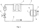
- the gravity-driven two-phase fluid loop system comprises an evaporator 1 (comprising a screen mesh evaporator 7, a liquid flow divider 8 and a steam converger 9), a steam pipeline 2, a condensation pipeline 3, a liquid reservoir 4, a liquid pipeline 6 and a control valve 5, wherein the condensation pipeline 3 is located above the gravity field of the liquid reservoir 4, the evaporator 1 is located below the gravity field of the liquid reservoir 4 and is coupled with the isotopic heat source, and a gravity-aided height difference is formed between the liquid level inside the liquid reservoir 4 and the bottom of the evaporator 1; and the liquid reservoir 4 is connected to an inlet of the evaporator 1 by the liquid pipeline 6 on which the control valve 5 is arranged, and an outlet of the evaporator 1 is connected to the liquid reservoir 4 sequentially by the steam pipeline 2 and the condensation pipeline 3 to form a closed pipeline system.
- evaporator 1 comprising a screen mesh evaporator 7, a liquid flow divider 8 and a steam converger 9
- ammonia is selected as a working medium.
- the control valve 5 of the gravity-driven two-phase fluid loop is opened to start the gravity-driven two-phase fluid loop and introduce heat of an isotopic nuclear heat source to the inside of a detector.
- the control valve 5 of the gravity-driven two-phase fluid loop is closed to stop the gravity-driven two-phase fluid loop and block the isotopic nuclear heat source from transferring the heat to the inside of the detector.
- the gravity-driven two-phase fluid loop technology can normally operate, and also ensure that the gravity-driven two-phase fluid loop can transfer the heat required by the system during the night on the moon and the gravity-driven two-phase fluid loop system can normally block the heat during the daylight on the moon, it is necessary to carry out a vacuum test on the gravity-driven two-phase fluid loop, it is required that the gravity-driven two-phase fluid loop is at a given stable working temperature (namely the temperature of the liquid reservoir 4), and the stable heat transfer quantity and the stable heat transfer temperature difference (the temperature difference of the evaporator 1 and the liquid reservoir 4) of the gravity-driven two-phase fluid loop meet technical indices.
- US 4 917 173 discloses also a vacuum heat performance testing device for a two phase fluid loop.
- the invention provides a vacuum heat performance testing device for a two-phase fluid loop, and by using the device, the heat transfer capacity and blocking performance of the two-phase fluid loop at different working temperatures can be tested and evaluated.
- the vacuum heat performance testing device of claim 1 solves the above mentioned technical problem.
- the temperature sensors are used for observing the state of the working medium ammonia in the gravity-driven two-phase fluid loop in each part, and the mounting positions of the temperature sensors are as follows:
- a substrate of the heat radiation plate (11) is a P plate or a honeycomb plate, and an OSR sheet is stuck to the surface of the heat radiation plate (11) or a coating with high emissivity is sprayed on the surface of the heat radiation plate (11).
- the temperature-controlled heaters are heating fins, heating wires, heating tapes or heating plates.
- the invention also provides a vacuum heat performance testing method for a two-phase fluid loop by using the testing device, and by using the method, the heat transfer capacity and blocking performance of the two-phase fluid loop at different working temperatures can be tested and evaluated.
- the testing method comprises the following steps:
- the heat insulation way of the evaporator 1, the simulated heat source 15 and the loop support 17 is shown as Fig. 3 , the evaporator 1 is mounted on a heat insulation plate 12, the simulated heat source 15 is placed inside the evaporator 1, a lug of a tool of the simulated heat source 15 is fixedly arranged on the heat insulation plate 12 by a screw and the heat insulation cushion 13, and the heat insulation plate 12 is fixedly mounted on the loop support 17 by four heat insulation columns 14, wherein the heat insulation plate 12, the heat insulation cushion 13 and the heat insulation columns 14 are made of a material with low heat conductivity, such as polyimide or glass fiber reinforced plastic.
- the distance from the lower surface of a liquid flow divider 8 to the upper surface of the heat insulation plate 12 is larger than 10 mm, the effective heat insulation distance from the heat insulation plate 12 to the loop support 17 is larger than 100 mm, and the external diameter of the heat insulation cushion 13 is less than 10 mm.
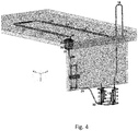
- the temperature sensors are thermocouple temperature sensors and are arranged as shown in Fig. 4 .
- the two-phase fluid loop is provided with the 34 temperature sensors:
- Positions where the temperature sensors are located serve as measuring point positions.
- the temperature-controlled heaters can heat in ways of heating fins, heating wires, heating tapes, heating plates or other ways and adopt a PID control or on/off temperature control way to mainly prevent each part in the two-phase fluid loop from being frozen, wherein the temperature-controlled heater on the liquid reservoir 4 is achieved by mounting two heating fins on the liquid reservoir 4 in a serial connection way; the temperature-controlled heater on the control valve 5 is achieved by mounting the heating tapes on the liquid pipeline connected with the control valve 5, as shown in Fig.
- each of (a pipeline between a measuring point 28 and a measuring point 29, a pipeline between the measuring point 29 and a measuring point 31, a pipeline between the measuring point 28 and a measuring point 30 and a pipeline between the measuring point 30 and the measuring point 31) is provided with one heating tape, the four heating tapes are connected in series, and each section of pipeline is about 50 mm long;
- the temperature-controlled heater on the liquid pipeline 6 is achieved by mounting one heating tape between the measuring point 31 and a measuring point 32 on the liquid pipeline 6;
- the temperature-controlled heater on the steam pipeline 2 is achieved by three heating tapes which are mounted in a serial connection way.
- the temperature-controlled heaters on the liquid reservoir 4, the control valve 5, the liquid pipeline 6 and the steam pipeline 2 mainly play a role in preventing the pipelines from being frozen.
- the temperature control of the evaporator 1 is realized by virtue of the simulated heat source 15 mounted inside the evaporator 1.
- the heat of the isotopic heat source is transferred and taken away by the two-phase fluid loop in a heat transfer process, so that the temperature of the surface of the isotopic heat source can also be reduced to be consistent with the temperature of the evaporator.
- the condensation pipeline 2 is pre-embedded into the heat radiation plate 11 so as to have substantially consistent temperature with the heat radiation plate 11, and the temperature control of the heat radiation plate 11 is realized by an infrared heater 16 mounted at the outer side of the heat radiation plate 11 or the heating fins stuck to the heat radiation plate, wherein the temperature of the heat radiation plate 11 is controlled at -60-50 ° C. Due to the heat transfer action of a working medium ammonia in the operating process of the two-phase fluid loop, the temperatures of the evaporator 1, the steam pipeline 2, the condensation pipeline 3, the liquid reservoir 4, the control valve 5 and the liquid pipeline 6 are basically maintained within the range of -55-50 ° C, wherein the temperature of the liquid reservoir 4 is the working temperature of the two-phase fluid loop.
- the heat radiation plate 11 and the two-phase fluid loop meet a temperature requirement or not is monitored by selecting measuring points T1 (at the lower part of the evaporator 1 and close to the outlet of the liquid pipeline 6), T3 (at the upper part of the evaporator 1 and close to the inlet of the steam pipeline 2), T14 (in the middle of the steam pipeline 2), T17 (at the inlet of the condensation pipeline 3), T23 (at the outlet of the condensation pipeline 3), T25 (at the upper part of the liquid reservoir 4, namely the gas space of the liquid reservoir), T27 (at the lower part of the liquid reservoir), T29-T30 (on a control valve a and a control valve b), T31 (at the inlet of the liquid pipeline 6) and T35-T38 (at the four corners of the heat radiation plate 11) as temperature monitoring points, and meanwhile, whether the balance is achieved or not is judged by comparing the temperatures of temperature monitoring points with the temperatures of other measuring points.
- the gravity-driven two-phase fluid loop is subjected to vacuum heat performance testing by using the testing device, so that the ultimate heat transfer capacity and blocking performance of the gravity-driven two-phase fluid loop at different working temperatures are tested, wherein the working temperature of the two-phase fluid loop is the temperature of the liquid reservoir 4, the temperature of the liquid reservoir 4 is changed by changing the temperatures of the evaporator 1 and the heat radiation plate 11 in the testing process, the temperature-controlled heaters on the liquid reservoir 4, the control valve 5, the liquid pipeline 6 and the steam pipeline 2 are only used for preventing each part in the two-phase fluid loop from being frozen, and the specific realization steps are as follows:
Landscapes
- Physics & Mathematics (AREA)
- Engineering & Computer Science (AREA)
- Life Sciences & Earth Sciences (AREA)
- Analytical Chemistry (AREA)
- Chemical & Material Sciences (AREA)
- Biochemistry (AREA)
- General Health & Medical Sciences (AREA)
- General Physics & Mathematics (AREA)
- Immunology (AREA)
- Pathology (AREA)
- Sustainable Development (AREA)
- Thermal Sciences (AREA)
- Health & Medical Sciences (AREA)
- Mechanical Engineering (AREA)
- General Engineering & Computer Science (AREA)
- Investigating Or Analyzing Materials Using Thermal Means (AREA)
Description
- The invention relates to the technical field of spacecraft heat control and particularly relates to a vacuum heat performance testing device and method for a two-phase fluid loop.
- A two-phase fluid loop technology is a spacecraft heat control technology emphatically developed at home and abroad in recent twenty years and mainly comprises a loop heat pipe technology, a mechanical-pump-driven two-phase fluid loop technology, a gravity-driven two-phase fluid loop technology and the like. A gravity-driven two-phase fluid loop system is a key technology for solving the problem that a rover and a lander in a Chang'e lunar exploration project cannot stay over the night on the moon, and heat of an isotopic heat source is brought into a loading cabin by the two-phase fluid loop system, so that the temperature of each equipment in the loading cabin is not too low. As shown in
Fig. 1 , the gravity-driven two-phase fluid loop system comprises an evaporator 1 (comprising ascreen mesh evaporator 7, aliquid flow divider 8 and a steam converger 9), asteam pipeline 2, acondensation pipeline 3, a liquid reservoir 4, aliquid pipeline 6 and acontrol valve 5, wherein thecondensation pipeline 3 is located above the gravity field of the liquid reservoir 4, theevaporator 1 is located below the gravity field of the liquid reservoir 4 and is coupled with the isotopic heat source, and a gravity-aided height difference is formed between the liquid level inside the liquid reservoir 4 and the bottom of theevaporator 1; and the liquid reservoir 4 is connected to an inlet of theevaporator 1 by theliquid pipeline 6 on which thecontrol valve 5 is arranged, and an outlet of theevaporator 1 is connected to the liquid reservoir 4 sequentially by thesteam pipeline 2 and thecondensation pipeline 3 to form a closed pipeline system. In order to ensure that a gravity-driven two-phase fluid loop has a favorable heat transfer characteristic within the temperature range of -50-70 ° C, ammonia is selected as a working medium. During the night on the moon, thecontrol valve 5 of the gravity-driven two-phase fluid loop is opened to start the gravity-driven two-phase fluid loop and introduce heat of an isotopic nuclear heat source to the inside of a detector. During the daylight on the moon, thecontrol valve 5 of the gravity-driven two-phase fluid loop is closed to stop the gravity-driven two-phase fluid loop and block the isotopic nuclear heat source from transferring the heat to the inside of the detector. - In order to ensure that the gravity-driven two-phase fluid loop technology can normally operate, and also ensure that the gravity-driven two-phase fluid loop can transfer the heat required by the system during the night on the moon and the gravity-driven two-phase fluid loop system can normally block the heat during the daylight on the moon, it is necessary to carry out a vacuum test on the gravity-driven two-phase fluid loop, it is required that the gravity-driven two-phase fluid loop is at a given stable working temperature (namely the temperature of the liquid reservoir 4), and the stable heat transfer quantity and the stable heat transfer temperature difference (the temperature difference of the
evaporator 1 and the liquid reservoir 4) of the gravity-driven two-phase fluid loop meet technical indices. - No fixed testing ways and methods are provided because the gravity-driven two-phase fluid loop technology is a novel heat control method for spacecraft heat control. Meanwhile, in consideration of the severe environment on the moon, a testing method for the heat transfer capacity and the blocking performance under the condition that the gravity-driven two-phase fluid loop is combined with the isotopic heat source is not found to be reported in a document and is required to be voluntarily researched, so that the on-orbit application of the gravity-driven two-phase fluid loop is directed.
-
US 4 917 173 discloses also a vacuum heat performance testing device for a two phase fluid loop. - In view of this, the invention provides a vacuum heat performance testing device for a two-phase fluid loop, and by using the device, the heat transfer capacity and blocking performance of the two-phase fluid loop at different working temperatures can be tested and evaluated.
- The vacuum heat performance testing device of
claim 1 solves the above mentioned technical problem. - The temperature sensors are used for observing the state of the working medium ammonia in the gravity-driven two-phase fluid loop in each part, and the mounting positions of the temperature sensors are as follows:
- each of four fins of the evaporator is provided with at least two temperature sensors along the height direction, wherein one of the temperature sensors is located at the lower end of each fin of the evaporator, and the other temperature sensor is located at the upper end of each fin of the evaporator;
- each of an inlet, the top and an outlet of the steam pipeline is provided with one temperature sensor;
- each of an inlet and an outlet of the condensation pipeline is provided with one temperature sensor, a fin of the condensation pipeline is provided with at least one temperature sensor;
- the outer surface of the liquid reservoir is provided with three temperature sensors along the height direction, and the three temperature sensors are respectively located in a gas space, a gas-liquid interface and a liquid space of the liquid reservoir;
- the liquid pipeline for connecting the liquid reservoir and the control valve is provided with at least one temperature sensor, and the liquid pipeline for connecting the control valve and the evaporator is provided with at least one temperature sensor;
- the control valve is provided with one temperature sensor;
- the simulated heat source is provided with at least one temperature sensor;
- the edge region of the inner surface of the heat radiation plate is provided with at least one temperature sensor;
- wherein the heat insulation plate (12), the heat insulation cushion (13) and the heat insulation columns (14) are made of polyimide or glass fiber reinforced plastic.
- A substrate of the heat radiation plate (11) is a P plate or a honeycomb plate, and an OSR sheet is stuck to the surface of the heat radiation plate (11) or a coating with high emissivity is sprayed on the surface of the heat radiation plate (11).
- The temperature-controlled heaters are heating fins, heating wires, heating tapes or heating plates.
- The invention also provides a vacuum heat performance testing method for a two-phase fluid loop by using the testing device, and by using the method, the heat transfer capacity and blocking performance of the two-phase fluid loop at different working temperatures can be tested and evaluated.
- The testing method comprises the following steps:
-
step 2, placing the loop support in the vacuum cabin, vacuumizing to make the vacuum degree less than 2×10⁻³ Pa, and setting the temperature-controlled heaters on the liquid reservoir, the control valve, the liquid pipeline and the steam pipeline in a self-control state and the self-control threshold to be -55 to -30 ° C; and setting the self-control threshold of the heat radiation plate heater to be -55 to -30 ° C; -
step 3, introducing liquid nitrogen to a heat sink of the vacuum cabin to reduce the temperature of the vacuum cabin to -150 ° C; reducing the temperature of the liquid reservoir to a first testing temperature -50 ° C, and realizing the balance of the working condition of the two-phase fluid loop; wherein the balance of the working condition means that the temperature of the liquid reservoir is maintained to be unchanged within half an hour or the monotonic change is less than 1 ° C/h; and the temperature of the liquid reservoir is the working temperature of the two-phase fluid loop; - step 4, testing the ultimate heat transfer capability:
starting the simulated heat source, increasing the heating power of the simulated heat source according to the set step length, and reducing the heating power of the heat radiation plate heater while increasing the heating power of the simulated heat source every time to maintain the temperature of the liquid reservoir at -50 ° C and realize the balance of the working condition of the two-phase fluid loop until the heating power of the heat radiation plate heater is zero or the balance of the working condition cannot be maintained because the temperature of the evaporator is suddenly raised; and determining the heating power of the simulated heat source at a balance moment when the heating power of the heat radiation plate heater is zero or before the temperature of the evaporator is suddenly raised as the ultimate heat transfer capability of the two-phase fluid loop at the working temperature; -
step 5, changing the temperature of the liquid reservoir to each testing temperature by increasing the power of the heat radiation plate while reducing the power of the evaporator, and carrying out the method in the step 4 to obtain the ultimate heat transfer capability of the two-phase fluid loop at each testing temperature, wherein the temperature of the liquid reservoir is changed according to a gradually-raising method; - and
step 6, testing the blocking capacity of the two-phase fluid loop:- when the two-phase fluid loop operates under a balanced working condition at different working temperatures, keeping the heating power of the simulated heat source and the heating power of the heat radiation plate heater unchanged, carrying out opening/closing operation on the control valve, and checking the blocking performance of the two-phase fluid loop: showing that the blocking performance of the two-phase fluid loop is normal if the temperature of the evaporator is suddenly raised after being continuously raised and the temperature of the heat radiation plate is continuously reduced after the control valve is closed, while the temperature of the evaporator is reduced and the temperature of the heat radiation plate is raised after the control valve is reopened until the working condition is balanced; and showing that the blocking performance of the two-phase fluid loop is abnormal if the temperature of the evaporator is unchanged or is stably raised after the control valve is closed;
- wherein the simulated heat source is started in the temperature reducing process in the
step 3 so that the two-phase fluid loop operates to accelerate the temperature reduction of the evaporator.
- The testing device and method have the beneficial effects that:
- (1) the heat transfer and blocking performance of the two-phase fluid loop in a vacuum environment can be comprehensively and effectively evaluated by using the testing device and method provided by the invention;
- (2) the substrate of the heat radiation plate selects an aluminum plate or the honeycomb plate, and the OSR sheet is stuck to the surface of the heat radiation plate or the coating with high emissivity is sprayed on the surface of the heat radiation plate so as to be beneficial to the increment of the heat radiation rate of the heat radiation plate;
- (3) the layout of the temperature sensors is beneficial to the observation of the state of the working medium ammonia in the two-phase fluid loop and can be used for checking whether each part in the two-phase fluid loop meets a temperature requirement or not and also checking whether the two-phase fluid loop is balanced or not;
- and (4) because the temperature reducing rates of the condensation pipeline and the evaporator are different, the temperature rise of the evaporator can be increased by increasing the heating power of the simulated heat source in the temperature reducing process, and the heat of the evaporator can be transferred to the condensation pipeline by the working medium ammonia in the two-phase fluid loop, so that the temperature reducing rate of the evaporator can be increased.
-
-
Fig. 1 is a schematic diagram of a gravity-driven two-phase fluid loop system; -
Fig. 2 is a schematic diagram of a vacuum heat performance testing device for a two-phase fluid loop; -
Fig. 3 is a schematic diagram of an evaporator of the two-phase fluid loop; -
Fig. 4 is a schematic diagram of the layout of temperature sensors on the two-phase fluid loop; -
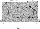
Fig. 5 is a schematic diagram of the layout of the temperature sensors on a heat radiation plate (comprising a condensation pipeline); - The invention is described in detail below in conjunction with the drawings and examples:
- The invention provides a vacuum heat performance testing device for a two-phase fluid loop, and as shown in
Fig. 2 , the vacuum heat performance testing device comprises aheat radiation plate 11, temperature-controlled heaters, multilayer heat insulation assemblies, temperature sensors, a simulatedheat source 15 and aloop support 17, - wherein the two-phase fluid loop and the
heat radiation plate 11 are mounted on theloop support 17 in a heat insulation way, theheat radiation plate 11 is mounted at the upper part of theloop support 17 in a way of heat insulation realized by a heat insulation cushion and is used for simulating an on-orbit heat radiation part of the two-phase fluid loop; acondensation pipeline 3 of the two-phase fluid loop is embedded in theheat radiation plate 11, and aliquid reservoir 14 of the two-phase fluid loop is semi-embedded in theheat radiation plate 11 and is located at an outlet of thecondensation pipeline 3; anevaporator 1 of the two-phase fluid loop is mounted at the lower part of theloop support 17 in a heat insulation way and is located below thecondensation pipeline 3; the temperature-controlled heaters are mounted on asteam pipeline 2, the liquid reservoir 4, acontrol valve 5 and aliquid pipeline 6 of the two-phase fluid loop and are used for preventing the pipelines from being frozen; the temperature sensors are mounted on theevaporator 1, thesteam pipeline 2, thecondensation pipeline 3, the liquid reservoir 4, thecontrol valve 5 and theliquid pipeline 6 of the two-phase fluid loop and theheat radiation plate 11 and are used for measuring the temperature of each part of the two-phase fluid loop and the temperature of the heat radiation plate and detecting the operation condition of the two-phase fluid loop; the multilayer heat insulation assemblies are mounted on thesteam pipeline 2, the liquid reservoir 4, thecontrol valve 5 and theliquid pipelines 6 and are used for avoiding heat leakage in parts of environments of the pipelines and simulating an on-orbit working condition; the simulatedheat source 15 adopts the RHU isotopic electric simulated heat source, is fixedly mounted in theevaporator 1, is used for simulating an isotopic heating device and is also the temperature-controlled heater of theevaporator 1; theloop support 17 is placed in avacuum cabin 10 by which a vacuum environment of which the temperature is not higher than 80 K and the vacuum degree is less than 2×10⁻³ Pa is provided; - wherein a substrate of the heat radiation plate can be made of a material with a relatively good heat conductivity, such as an aluminum plate or a honeycomb plate, and an OSR sheet is stuck to the outer surface of the heat radiation plate or a coating with high emissivity is sprayed on the outer surface of the heat radiation plate so as to be beneficial to heat radiation.
- The heat insulation way of the
evaporator 1, the simulatedheat source 15 and theloop support 17 is shown asFig. 3 , theevaporator 1 is mounted on aheat insulation plate 12, the simulatedheat source 15 is placed inside theevaporator 1, a lug of a tool of the simulatedheat source 15 is fixedly arranged on theheat insulation plate 12 by a screw and theheat insulation cushion 13, and theheat insulation plate 12 is fixedly mounted on theloop support 17 by fourheat insulation columns 14, wherein theheat insulation plate 12, theheat insulation cushion 13 and theheat insulation columns 14 are made of a material with low heat conductivity, such as polyimide or glass fiber reinforced plastic. The distance from the lower surface of aliquid flow divider 8 to the upper surface of theheat insulation plate 12 is larger than 10 mm, the effective heat insulation distance from theheat insulation plate 12 to theloop support 17 is larger than 100 mm, and the external diameter of theheat insulation cushion 13 is less than 10 mm. - The temperature sensors are thermocouple temperature sensors and are arranged as shown in
Fig. 4 . The two-phase fluid loop is provided with the 34 temperature sensors: - (1) each of four fins of the
evaporator 1 is uniformly provided with three temperature sensors from bottom to top along the height direction, namely the four fins of theevaporator 1 are provided with twelve temperature sensors with serial numbers T1-T12 in total, or only the lower and lower ends of the fins of the evaporator are provided with the sensors, and the temperature sensors are mainly used for measuring the temperatures of a liquid working medium and a gaseous working medium in the evaporator, so that the working state of theevaporator 1 is reflected. - (2) each of an inlet, the top and an outlet of the
steam pipeline 2 is provided with one temperature sensor, and the serial numbers of the temperature sensors are respectively T13, T14 and T15. - (3) as shown in
Fig. 5 , an inlet and an outlet of thecondensation pipeline 3 and the condensation pipeline are provided with nine temperature sensors with serial numbers T16-T24; and thecondensation pipeline 3 is generally provided with a fin for increasing the heat radiation area, and the temperature sensors are generally mounted on the fin. - (4) the outer surface of the liquid reservoir 4 is provided with three temperature sensors with serial numbers T25-T27 along the height direction, and the three temperature sensors are respectively used for measuring the temperature of a gas, a gas-liquid interface and a liquid in the liquid reservoir 4.
- (5) the
liquid pipeline 6 is divided into two sections, one section is connected with the liquid reservoir 4 and thecontrol valve 5, and the other section is connected with thecontrol valve 5 and theevaporator 1, wherein the middle point of the liquid pipeline for connecting the liquid reservoir 4 and thecontrol valve 5 is provided with one temperature sensor with a serial number T28; and each of an inlet and an outlet of the liquid pipeline for connecting thecontrol valve 5 and theevaporator 1 is provided with one temperature sensor, and the temperature sensors respectively have the serial numbers of T31 and T32, or the middle point of the liquid pipeline for connecting thecontrol valve 5 and theevaporator 1 is provided with one temperature sensor. - (6) the
control valve 5 is provided with the temperature sensors; and if thecontrol valve 5 is composed of two parallel valves (a valve a and a valve b), each of the valve a and the valve b is provided with one temperature sensor, and the temperature sensors have the serial numbers T29 and T30. - (7) the simulated heat source is provided with two temperature sensors with the serial numbers T33 and T34.
- and (8) as shown in
Fig. 5 , the edge region of the inner surface of theheat radiation plate 11 is provided with four temperature sensors with serial numbers T35 and T38, and the four temperature sensors are 100 mm away from the edge of the heat radiation plate. - Positions where the temperature sensors are located serve as measuring point positions.
- The temperature-controlled heaters can heat in ways of heating fins, heating wires, heating tapes, heating plates or other ways and adopt a PID control or on/off temperature control way to mainly prevent each part in the two-phase fluid loop from being frozen, wherein the temperature-controlled heater on the liquid reservoir 4 is achieved by mounting two heating fins on the liquid reservoir 4 in a serial connection way; the temperature-controlled heater on the control valve 5 is achieved by mounting the heating tapes on the liquid pipeline connected with the control valve 5, as shown in
Fig. 2 , each of (a pipeline between a measuring point 28 and a measuring point 29, a pipeline between the measuring point 29 and a measuring point 31, a pipeline between the measuring point 28 and a measuring point 30 and a pipeline between the measuring point 30 and the measuring point 31) is provided with one heating tape, the four heating tapes are connected in series, and each section of pipeline is about 50 mm long; the temperature-controlled heater on the liquid pipeline 6 is achieved by mounting one heating tape between the measuring point 31 and a measuring point 32 on the liquid pipeline 6; and the temperature-controlled heater on the steam pipeline 2 is achieved by three heating tapes which are mounted in a serial connection way. - The temperature-controlled heaters on the liquid reservoir 4, the
control valve 5, theliquid pipeline 6 and thesteam pipeline 2 mainly play a role in preventing the pipelines from being frozen. - The temperature control of the
evaporator 1 is realized by virtue of thesimulated heat source 15 mounted inside theevaporator 1. The heat of the isotopic heat source is transferred and taken away by the two-phase fluid loop in a heat transfer process, so that the temperature of the surface of the isotopic heat source can also be reduced to be consistent with the temperature of the evaporator. - The
condensation pipeline 2 is pre-embedded into theheat radiation plate 11 so as to have substantially consistent temperature with theheat radiation plate 11, and the temperature control of theheat radiation plate 11 is realized by aninfrared heater 16 mounted at the outer side of theheat radiation plate 11 or the heating fins stuck to the heat radiation plate,
wherein the temperature of theheat radiation plate 11 is controlled at -60-50 ° C. Due to the heat transfer action of a working medium ammonia in the operating process of the two-phase fluid loop, the temperatures of theevaporator 1, thesteam pipeline 2, thecondensation pipeline 3, the liquid reservoir 4, thecontrol valve 5 and theliquid pipeline 6 are basically maintained within the range of -55-50 ° C, wherein the temperature of the liquid reservoir 4 is the working temperature of the two-phase fluid loop. - Whether the
simulated heat source 15, theheat radiation plate 11 and the two-phase fluid loop meet a temperature requirement or not is monitored by selecting measuring points T1 (at the lower part of theevaporator 1 and close to the outlet of the liquid pipeline 6), T3 (at the upper part of theevaporator 1 and close to the inlet of the steam pipeline 2), T14 (in the middle of the steam pipeline 2), T17 (at the inlet of the condensation pipeline 3), T23 (at the outlet of the condensation pipeline 3), T25 (at the upper part of the liquid reservoir 4, namely the gas space of the liquid reservoir), T27 (at the lower part of the liquid reservoir), T29-T30 (on a control valve a and a control valve b), T31 (at the inlet of the liquid pipeline 6) and T35-T38 (at the four corners of the heat radiation plate 11) as temperature monitoring points, and meanwhile, whether the balance is achieved or not is judged by comparing the temperatures of temperature monitoring points with the temperatures of other measuring points. - The gravity-driven two-phase fluid loop is subjected to vacuum heat performance testing by using the testing device, so that the ultimate heat transfer capacity and blocking performance of the gravity-driven two-phase fluid loop at different working temperatures are tested, wherein the working temperature of the two-phase fluid loop is the temperature of the liquid reservoir 4, the temperature of the liquid reservoir 4 is changed by changing the temperatures of the
evaporator 1 and theheat radiation plate 11 in the testing process, the temperature-controlled heaters on the liquid reservoir 4, thecontrol valve 5, theliquid pipeline 6 and thesteam pipeline 2 are only used for preventing each part in the two-phase fluid loop from being frozen, and the specific realization steps are as follows: -
step 1, placing theloop support 17 in thevacuum cabin 10, vacuumizing (the vacuum degree is less than 2×10⁻³ Pa), and setting the temperature-controlled heaters on the liquid reservoir 4, thecontrol valve 5, theliquid pipeline 6 and thesteam pipeline 2 in a self-control state and the self-control threshold to be -55 to -30 ° C, namely automatically starting the temperature-controlled heaters when the temperature is less than the self-control threshold to prevent the pipelines from being frozen; and setting the self-control threshold of a heat radiation plate heater to be -55 to -30 ° C; -
step 2, introducing liquid nitrogen to a heat sink of the vacuum cabin, reducing the temperature of the vacuum cabin to -150 ° C, wherein the steam pipeline (2), the liquid reservoir (4), the control valve (5) and the liquid pipeline (6) of the two-phase fluid loop are wrapped by the multilayer heat insulation assemblies, so that the temperature reducing rate of the two-phase fluid loop is low, and the temperature reducing rate of the heat radiation plate is highest, in order to increase the temperature reducing rate of each part in the two-phase fluid loop, starting thesimulated heat source 15 in the temperature reducing process to make the two-phase fluid loop operate, driving the evaporator and the liquid reservoir to reduce the temperatures by the condensation pipeline in the heat radiation plate, accelerating the temperature reduction of the evaporator until the temperature of the liquid reservoir is reduced to -50 ° C, and when the temperature of the liquid reservoir is maintained to be unchanged within half an hour or the monotonic change is less than 1 ° C/h, considering that the working condition is balanced, wherein the temperature of the liquid reservoir is the working temperature of the two-phase fluid loop; - step 3, testing the ultimate heat transfer capability: increasing the heating power of the evaporator (namely the heating power of the simulated heat source) according to a certain step length, and synchronously reducing the heating power of the heat radiation plate heater while increasing the heating power of the simulated heat source every time to maintain the temperature of the liquid reservoir at -50 ° C, waiting for the balance of the working condition of the two-phase fluid loop after regulating the heating power every time until the heating power of the heat radiation plate heater is zero or the balance of the working condition cannot be maintained because the temperature of the evaporator is suddenly raised; wherein when the heating power of the heat radiation plate is zero, the heat radiation plate achieves the maximum heat radiation capacity at the working temperature, the further increment of the heating power of the evaporator can result in the temperature rise of the liquid reservoir, and the temperature of the liquid reservoir cannot be further maintained at -50 ° C, when the heating power of the evaporator is higher than the ultimate heat transfer capability of the two-phase fluid loop, a liquid in the evaporator is dry to result in the sudden rise of the temperature of the evaporator, and therefore, determining the heating power of the evaporator at a balance moment when the heating power of the heat radiation plate heater is zero or before the temperature of the evaporator is suddenly raised as the ultimate heat transfer capability of the two-phase fluid loop at the working temperature;
- step 4, changing the temperature of the liquid reservoir by increasing the power of the heat radiation plate while reducing the power of the evaporator, and carrying out the method in the
step 3 to obtain the ultimate heat transfer capabilities of the two-phase fluid loop at different working temperatures, wherein when the ultimate heat transfer capability of the two-phase fluid loop at different working temperatures is tested, the working temperatures are regulated by using a gradually-raising method, for example, the ultimate heat transfer capability when the working temperature is -50 ° C is firstly tested, and then, the ultimate heat transfer capabilities when the working temperatures are -40 ° C, -30 ° C, -20 ° C and the like are sequentially tested. - and
step 5, testing the blocking capacity of the two-phase fluid loop:
when the two-phase fluid loop operates under a balanced working condition at different working temperatures, keeping the heating power of the evaporator and the heating power of the heat radiation plate heater unchanged, carrying out opening/closing operation on the valve of the gravity-driven two-phase fluid loop, and checking the blocking performance of the two-phase fluid loop: showing that the blocking performance of the two-phase fluid loop is normal if the temperature of the evaporator is continuously raised and is suddenly raised and the temperature of the heat radiation plate is continuously reduced after the control valve is closed, while the temperature of the evaporator is reduced and the temperature of the heat radiation plate is raised after the control valve is reopened until the working condition is balanced; and showing that the blocking performance of the two-phase fluid loop is abnormal if the temperature of the evaporator is unchanged or is slowly raised after the control valve is closed. - In summary, merely preferred embodiments of the invention have been described above and are not intended to limit the scope of the invention.
Claims (7)
- A vacuum heat performance testing device for a two-phase fluid loop comprising a heat radiation plate (11), temperature-controlled heaters, multilayer heat insulation assemblies, temperature sensors, a simulated heat source (15) and a loop support (17), wherein the heat radiation plate (11) is mounted at the upper part of the loop support (17) in a way of heat insulation realized by a heat insulation cushion; a condensation pipeline (3) of the two-phase fluid loop is embedded in the heat radiation plate (11), and a liquid reservoir (4) of the two-phase fluid loop is semi-embedded in the heat radiation plate (11); an evaporator (1) of the two-phase fluid loop is mounted at the lower part of the loop support (17) in a heat insulation way; the temperature-controlled heaters are mounted on a steam pipeline (2), the liquid reservoir (4), a control valve (5) and a liquid pipeline (6) of the two-phase fluid loop; the temperature sensors are mounted on edge regions of the evaporator (1), the steam pipeline (2), the condensation pipeline (3), the liquid reservoir (4), the control valve (5), the liquid pipeline (6), the simulated heat source (15) and the heat radiation plate (11); the steam pipeline (2), the liquid reservoir (4), the control valve (5) and the liquid pipeline (6) are wrapped by the multilayer heat insulation assemblies; the simulated heat source (15) is an RHU isotopic electric simulated heat source and is fixedly mounted in the evaporator (1); a heat radiation plate heater for providing a working temperature for the heat radiation plate (11) is mounted, and the heat radiation plate heater is an infrared heater (16) mounted in a space at the outer side of the heat radiation plate or heating fins stuck to the heat radiation plate; the loop support (17) is placed in a vacuum cabin (10);
wherein the evaporator (1) is mounted on a heat insulation plate (12), the simulated heat source (15) is placed inside the evaporator (1), a lug of a tool of the simulated heat source (15) is fixedly arranged on the heat insulation plate (12) by a screw and a heat insulation cushion (13), and the heat insulation plate (12) is fixedly mounted on the loop support (17) by four heat insulation columns (14);
the simulated heat source (15) is used for controlling the temperature of the evaporator and maintaining the temperature of the evaporator (1) at -55-50 ° C; the heat radiation plate heater is used for controlling the temperature of the heat radiation plate (11) and maintaining the temperature of the heat radiation plate (11) at -60-50 ° C; and the temperature-controlled heaters are used for preventing the steam pipeline (2), the liquid reservoir (4), the control valve (5) and the liquid pipeline (6) from being frozen, and self-control thresholds of the temperature-controlled heaters are set to be -55 to -30 ° C. - The vacuum heat performance testing device for the two-phase fluid loop of claim 1, characterized in that the mounting positions of the temperature sensors are as follows:each of four fins of the evaporator (1) is provided with at least two temperature sensors along the height direction, wherein one of the temperature sensors is located at the lower end of each fin of the evaporator, and the other temperature sensor is located at the upper end of each fin of the evaporator;each of an inlet, a top and an outlet of the steam pipeline (2) is provided with one temperature sensor;each of an inlet and an outlet of the condensation pipeline (3) is provided with one temperature sensor, a fin of the condensation pipeline (3) is provided with at least one temperature sensor;an outer surface of the liquid reservoir (4) is provided with three temperature sensors along the height direction, and the three temperature sensors are respectively located in a gas space, a gas-liquid interface and a liquid space of the liquid reservoir (4);the liquid pipeline for connecting the liquid reservoir (4) and the control valve (5) is provided with at least one temperature sensor, and the liquid pipeline for connecting the control valve (5) and the evaporator (1) is provided with at least one temperature sensor;the control valve (5) is provided with one temperature sensor;the simulated heat source (15) is provided with at least one temperature sensor;and the edge region of an inner surface of the heat radiation plate (11) is provided with at least one temperature sensor.
- The vacuum heat performance testing device for the two-phase fluid loop of claim 1, characterized in that the heat insulation plate (12), the heat insulation cushion (13) and the heat insulation columns (14) are made of polyimide or glass fiber reinforced plastic.
- The vacuum heat performance testing device for the two-phase fluid loop of claim 1, characterized in that a substrate of the heat radiation plate (11) is an aluminum plate or a honeycomb plate, and an OSR sheet is stuck to a surface of the heat radiation plate (11) or a coating with high emissivity is sprayed on the surface of the heat radiation plate (11).
- The vacuum heat performance testing device for the two-phase fluid loop of claim 1, characterized in that the temperature-controlled heaters are heating fins, heating wires, heating tapes or heating plates.
- A vacuum heat performance testing method for a two-phase fluid loop by using the testing device of any one of claims 1-5, characterized by comprising the following steps:step 1, placing the loop support (17) in the vacuum cabin (10), vacuumizing to make the vacuum degree less than 2×10⁻³ Pa, and setting the temperature-controlled heaters on the liquid reservoir (4), the control valve (5), the liquid pipeline (6) and the steam pipeline (2) in a self-control state and the self-control threshold to be -55 to -30 ° C; and setting the self-control threshold of a heat radiation plate heater to be -55 to -30 ° C;step 2, introducing liquid nitrogen to a heat sink of the vacuum cabin (10) to reduce the temperature of the vacuum cabin to -150 ° C; reducing the temperature of the liquid reservoir to a first testing temperature -50 ° C, and realizing the balance of the working condition of the two-phase fluid loop; wherein the balance of the working condition means that the temperature of the liquid reservoir is maintained to be unchanged within half an hour or the monotonic change is less than 1 ° C/h; and the temperature of the liquid reservoir is the working temperature of the two-phase fluid loop;step 3, testing the ultimate heat transfer capability:
starting the simulated heat source, increasing the heating power of the simulated heat source according to the set step length, and reducing the heating power of the heat radiation plate heater while increasing the heating power of the simulated heat source every time to maintain the temperature of the liquid reservoir at -50 ° C and realize the balance of the working condition of the two-phase fluid loop until the heating power of the heat radiation plate heater is zero or the balance of the working condition cannot be maintained because the temperature of the evaporator is suddenly raised; and therefore, determining the heating power of the simulated heat source at a balance moment when the heating power of the heat radiation plate heater is zero or before the temperature of the evaporator is suddenly raised as the ultimate heat transfer capability of the two-phase fluid loop at the working temperature;step 4, changing the temperature of the liquid reservoir to each testing temperature by increasing the power of the heat radiation plate while reducing the power of the evaporator, and carrying out the method in the step 3 to obtain the ultimate heat transfer capability of the two-phase fluid loop at each testing temperature, wherein the temperature of the liquid reservoir is changed by using a gradually-raising method;and step 5, testing the blocking capacity of the two-phase fluid loop:
when the two-phase fluid loop operates under a balanced working condition at different working temperatures, keeping the heating power of the simulated heat source and the heating power of the heat radiation plate heater unchanged, carrying out opening/closing operation on the control valve, and checking the blocking performance of the two-phase fluid loop: showing that the blocking performance of the two-phase fluid loop is normal if the temperature of the evaporator is suddenly raised after being continuously raised and the temperature of the heat radiation plate is continuously reduced after the control valve is closed, while the temperature of the evaporator is reduced and the temperature of the heat radiation plate is raised after the control valve is reopened until the working condition is balanced; and showing that the blocking performance of the two-phase fluid loop is abnormal if the temperature of the evaporator is unchanged or is stably raised after the control valve is closed. - The vacuum heat performance testing method for the two-phase fluid loop of claim 6, characterized in that the simulated heat source (15) is started in the temperature reducing process in the step 2 so that the two-phase fluid loop operates to accelerate the temperature reduction of the evaporator (1).
Applications Claiming Priority (3)
| Application Number | Priority Date | Filing Date | Title |
|---|---|---|---|
| CN201410720161.8A CN104483147A (en) | 2014-12-02 | 2014-12-02 | Vacuum thermal performance testing device for two-phase fluid loop |
| CN201410720854.7A CN104483346B (en) | 2014-12-02 | 2014-12-02 | A kind of two-phase fluid loop vacuum thermal characteristics test method |
| PCT/CN2015/000834 WO2016086504A1 (en) | 2014-12-02 | 2015-12-28 | Vacuum thermal performance test device for two-phase fluid loop, and method |
Publications (3)
| Publication Number | Publication Date |
|---|---|
| EP3229015A1 EP3229015A1 (en) | 2017-10-11 |
| EP3229015A4 EP3229015A4 (en) | 2018-08-22 |
| EP3229015B1 true EP3229015B1 (en) | 2019-10-30 |
Family
ID=56090886
Family Applications (1)
| Application Number | Title | Priority Date | Filing Date |
|---|---|---|---|
| EP15866124.9A Active EP3229015B1 (en) | 2014-12-02 | 2015-12-28 | Vacuum thermal performance test device for two-phase fluid loop, and method |
Country Status (2)
| Country | Link |
|---|---|
| EP (1) | EP3229015B1 (en) |
| WO (1) | WO2016086504A1 (en) |
Families Citing this family (6)
| Publication number | Priority date | Publication date | Assignee | Title |
|---|---|---|---|---|
| AT519232B1 (en) * | 2017-01-16 | 2018-05-15 | Cryoshelter Gmbh | Apparatus and method for determining the thermal insulation quality of double-walled vacuum-insulated containers |
| CN110596745B (en) * | 2019-09-09 | 2022-05-10 | 中国工程物理研究院核物理与化学研究所 | Electric heating simulated heat source of general isotope heat source |
| CN111766267B (en) * | 2020-08-14 | 2025-09-09 | 中国电子科技集团公司第三十八研究所 | Heat dissipation performance testing device |
| CN113815908B (en) * | 2020-11-05 | 2024-03-08 | 山东大学 | Intelligent heat-preserving loop heat pipe and heat control system thereof |
| CN114544697A (en) * | 2022-02-08 | 2022-05-27 | 北京卫星环境工程研究所 | A heat dissipation device for vacuum thermal test and method for enhancing heat dissipation |
| CN116559225B (en) * | 2023-03-31 | 2025-09-23 | 扬州睿炬科技有限公司 | A thermal assessment test equipment for aerospace parts materials |
Family Cites Families (10)
| Publication number | Priority date | Publication date | Assignee | Title |
|---|---|---|---|---|
| ATE49303T1 (en) * | 1984-09-21 | 1990-01-15 | Siemens Ag | EQUIPMENT FOR FUNCTIONAL TESTING OF INTEGRATED CIRCUITS. |
| US4917173A (en) * | 1988-11-15 | 1990-04-17 | The United States Of America As Represented By The National Aeronautics And Space Administration | Monogroove liquid heat exchanger |
| CN100561207C (en) * | 2005-11-25 | 2009-11-18 | 富准精密工业(深圳)有限公司 | Heat pipe performance testing device |
| GB2498373B (en) * | 2012-01-12 | 2016-08-31 | ECONOTHERM UK Ltd | Heat exchanger |
| CN103232836B (en) * | 2013-05-07 | 2015-07-01 | 中国科学院近代物理研究所 | Heat exchange medium, heat exchange system and nuclear reactor system |
| CN203512059U (en) * | 2013-08-12 | 2014-04-02 | 上海卫星工程研究所 | High-efficiency spacecraft thermal management system |
| CN103482087B (en) * | 2013-08-12 | 2016-06-22 | 上海卫星工程研究所 | A kind of heat control device suitable in Mars landing device |
| CN104483147A (en) * | 2014-12-02 | 2015-04-01 | 北京空间飞行器总体设计部 | Vacuum thermal performance testing device for two-phase fluid loop |
| CN104502392B (en) * | 2014-12-02 | 2016-05-11 | 北京空间飞行器总体设计部 | Failure test method is freezed in a kind of two-phase fluid loop |
| CN104483346B (en) * | 2014-12-02 | 2016-06-01 | 北京空间飞行器总体设计部 | A kind of two-phase fluid loop vacuum thermal characteristics test method |
-
2015
- 2015-12-28 WO PCT/CN2015/000834 patent/WO2016086504A1/en not_active Ceased
- 2015-12-28 EP EP15866124.9A patent/EP3229015B1/en active Active
Non-Patent Citations (1)
| Title |
|---|
| None * |
Also Published As
| Publication number | Publication date |
|---|---|
| EP3229015A1 (en) | 2017-10-11 |
| WO2016086504A1 (en) | 2016-06-09 |
| EP3229015A4 (en) | 2018-08-22 |
Similar Documents
| Publication | Publication Date | Title |
|---|---|---|
| EP3229015A1 (en) | Vacuum thermal performance test device for two-phase fluid loop, and method | |
| Fang et al. | Influence of furnace design on the thermal stress during directional solidification of multicrystalline silicon | |
| CN103847951A (en) | High heat transfer rate reusable thermal protection system | |
| Wang et al. | Influence of flow distribution on the thermal performance of dual-media thermocline energy storage systems | |
| CN113371236A (en) | Wide-temperature-zone space environment simulation test system and method | |
| CN104483147A (en) | Vacuum thermal performance testing device for two-phase fluid loop | |
| CN103853203A (en) | Cooling device | |
| CN103482087B (en) | A kind of heat control device suitable in Mars landing device | |
| CN103914092A (en) | Temperature control method for equipment on satellite in system level thermal vacuum test | |
| US20150247895A1 (en) | Test Handler and Circulation Method of Test Trays in Test Handler | |
| CN104483346A (en) | Method for testing vacuum thermal performance of two-phase fluid loop | |
| CN106325063A (en) | A method and device for rapid cooling | |
| Schwager et al. | Advanced two phase flow model for transient molten salt receiver system simulation | |
| Esence et al. | Extended modeling of packed-bed sensible heat storage systems | |
| CN104502392B (en) | Failure test method is freezed in a kind of two-phase fluid loop | |
| CN116119044A (en) | Space environment simulator for multi-sample thermal vacuum test | |
| US9574711B2 (en) | Method and system for regulating cryogenic vapor pressure | |
| JP2018123878A (en) | Liquefied gas supply method | |
| Akber et al. | Numerical investigation of thermo-fluid behaviour in a channel with PCM-filled columns | |
| KR101939329B1 (en) | Cryogenic gas generator | |
| CN201754152U (en) | Testing device for determination of concrete thermal diffusivity | |
| JP2013190368A (en) | Pressure control unit, and environmental test device | |
| CN203204467U (en) | Programmed temperature lowering instrument | |
| Yuan et al. | Active cooling system for Tokamak in-vessel operation manipulator | |
| Mitsuishi et al. | He flow rate measurements on the engineering model for the Astro-H soft x-ray spectrometer dewar |
Legal Events
| Date | Code | Title | Description |
|---|---|---|---|
| STAA | Information on the status of an ep patent application or granted ep patent |
Free format text: STATUS: THE INTERNATIONAL PUBLICATION HAS BEEN MADE |
|
| PUAI | Public reference made under article 153(3) epc to a published international application that has entered the european phase |
Free format text: ORIGINAL CODE: 0009012 |
|
| STAA | Information on the status of an ep patent application or granted ep patent |
Free format text: STATUS: REQUEST FOR EXAMINATION WAS MADE |
|
| 17P | Request for examination filed |
Effective date: 20170630 |
|
| AK | Designated contracting states |
Kind code of ref document: A1 Designated state(s): AL AT BE BG CH CY CZ DE DK EE ES FI FR GB GR HR HU IE IS IT LI LT LU LV MC MK MT NL NO PL PT RO RS SE SI SK SM TR |
|
| AX | Request for extension of the european patent |
Extension state: BA ME |
|
| XX | Miscellaneous (additional remarks) |
Free format text: THE FILING DATE OF THE INTERNATIONAL APPLICATION IS WITHIN TWO MONTHS FROM THE DATE OF EXPIRATION OF THE PRIORITY PERIOD (R. 26BIS.3 PCT). |
|
| DAV | Request for validation of the european patent (deleted) | ||
| DAX | Request for extension of the european patent (deleted) | ||
| A4 | Supplementary search report drawn up and despatched |
Effective date: 20180725 |
|
| RIC1 | Information provided on ipc code assigned before grant |
Ipc: G01N 25/20 20060101AFI20180719BHEP Ipc: F28D 15/02 20060101ALI20180719BHEP |
|
| GRAP | Despatch of communication of intention to grant a patent |
Free format text: ORIGINAL CODE: EPIDOSNIGR1 |
|
| STAA | Information on the status of an ep patent application or granted ep patent |
Free format text: STATUS: GRANT OF PATENT IS INTENDED |
|
| INTG | Intention to grant announced |
Effective date: 20190529 |
|
| GRAS | Grant fee paid |
Free format text: ORIGINAL CODE: EPIDOSNIGR3 |
|
| GRAA | (expected) grant |
Free format text: ORIGINAL CODE: 0009210 |
|
| STAA | Information on the status of an ep patent application or granted ep patent |
Free format text: STATUS: THE PATENT HAS BEEN GRANTED |
|
| AK | Designated contracting states |
Kind code of ref document: B1 Designated state(s): AL AT BE BG CH CY CZ DE DK EE ES FI FR GB GR HR HU IE IS IT LI LT LU LV MC MK MT NL NO PL PT RO RS SE SI SK SM TR |
|
| REG | Reference to a national code |
Ref country code: GB Ref legal event code: FG4D |
|
| XX | Miscellaneous (additional remarks) |
Free format text: THE FILING DATE OF THE INTERNATIONAL APPLICATION IS WITHIN TWO MONTHS FROM THE DATE OF EXPIRATION OF THE PRIORITY PERIOD (R. 26BIS.3 PCT). |
|
| REG | Reference to a national code |
Ref country code: CH Ref legal event code: EP |
|
| REG | Reference to a national code |
Ref country code: AT Ref legal event code: REF Ref document number: 1196703 Country of ref document: AT Kind code of ref document: T Effective date: 20191115 |
|
| REG | Reference to a national code |
Ref country code: DE Ref legal event code: R096 Ref document number: 602015040881 Country of ref document: DE |
|
| REG | Reference to a national code |
Ref country code: IE Ref legal event code: FG4D |
|
| REG | Reference to a national code |
Ref country code: LT Ref legal event code: MG4D |
|
| PG25 | Lapsed in a contracting state [announced via postgrant information from national office to epo] |
Ref country code: NO Free format text: LAPSE BECAUSE OF FAILURE TO SUBMIT A TRANSLATION OF THE DESCRIPTION OR TO PAY THE FEE WITHIN THE PRESCRIBED TIME-LIMIT Effective date: 20200130 Ref country code: BG Free format text: LAPSE BECAUSE OF FAILURE TO SUBMIT A TRANSLATION OF THE DESCRIPTION OR TO PAY THE FEE WITHIN THE PRESCRIBED TIME-LIMIT Effective date: 20200130 Ref country code: LT Free format text: LAPSE BECAUSE OF FAILURE TO SUBMIT A TRANSLATION OF THE DESCRIPTION OR TO PAY THE FEE WITHIN THE PRESCRIBED TIME-LIMIT Effective date: 20191030 Ref country code: FI Free format text: LAPSE BECAUSE OF FAILURE TO SUBMIT A TRANSLATION OF THE DESCRIPTION OR TO PAY THE FEE WITHIN THE PRESCRIBED TIME-LIMIT Effective date: 20191030 Ref country code: NL Free format text: LAPSE BECAUSE OF FAILURE TO SUBMIT A TRANSLATION OF THE DESCRIPTION OR TO PAY THE FEE WITHIN THE PRESCRIBED TIME-LIMIT Effective date: 20191030 Ref country code: PT Free format text: LAPSE BECAUSE OF FAILURE TO SUBMIT A TRANSLATION OF THE DESCRIPTION OR TO PAY THE FEE WITHIN THE PRESCRIBED TIME-LIMIT Effective date: 20200302 Ref country code: LV Free format text: LAPSE BECAUSE OF FAILURE TO SUBMIT A TRANSLATION OF THE DESCRIPTION OR TO PAY THE FEE WITHIN THE PRESCRIBED TIME-LIMIT Effective date: 20191030 Ref country code: SE Free format text: LAPSE BECAUSE OF FAILURE TO SUBMIT A TRANSLATION OF THE DESCRIPTION OR TO PAY THE FEE WITHIN THE PRESCRIBED TIME-LIMIT Effective date: 20191030 Ref country code: GR Free format text: LAPSE BECAUSE OF FAILURE TO SUBMIT A TRANSLATION OF THE DESCRIPTION OR TO PAY THE FEE WITHIN THE PRESCRIBED TIME-LIMIT Effective date: 20200131 Ref country code: PL Free format text: LAPSE BECAUSE OF FAILURE TO SUBMIT A TRANSLATION OF THE DESCRIPTION OR TO PAY THE FEE WITHIN THE PRESCRIBED TIME-LIMIT Effective date: 20191030 |
|
| REG | Reference to a national code |
Ref country code: NL Ref legal event code: MP Effective date: 20191030 |
|
| PG25 | Lapsed in a contracting state [announced via postgrant information from national office to epo] |
Ref country code: IS Free format text: LAPSE BECAUSE OF FAILURE TO SUBMIT A TRANSLATION OF THE DESCRIPTION OR TO PAY THE FEE WITHIN THE PRESCRIBED TIME-LIMIT Effective date: 20200229 Ref country code: HR Free format text: LAPSE BECAUSE OF FAILURE TO SUBMIT A TRANSLATION OF THE DESCRIPTION OR TO PAY THE FEE WITHIN THE PRESCRIBED TIME-LIMIT Effective date: 20191030 Ref country code: RS Free format text: LAPSE BECAUSE OF FAILURE TO SUBMIT A TRANSLATION OF THE DESCRIPTION OR TO PAY THE FEE WITHIN THE PRESCRIBED TIME-LIMIT Effective date: 20191030 |
|
| PG25 | Lapsed in a contracting state [announced via postgrant information from national office to epo] |
Ref country code: AL Free format text: LAPSE BECAUSE OF FAILURE TO SUBMIT A TRANSLATION OF THE DESCRIPTION OR TO PAY THE FEE WITHIN THE PRESCRIBED TIME-LIMIT Effective date: 20191030 |
|
| PG25 | Lapsed in a contracting state [announced via postgrant information from national office to epo] |
Ref country code: CZ Free format text: LAPSE BECAUSE OF FAILURE TO SUBMIT A TRANSLATION OF THE DESCRIPTION OR TO PAY THE FEE WITHIN THE PRESCRIBED TIME-LIMIT Effective date: 20191030 Ref country code: RO Free format text: LAPSE BECAUSE OF FAILURE TO SUBMIT A TRANSLATION OF THE DESCRIPTION OR TO PAY THE FEE WITHIN THE PRESCRIBED TIME-LIMIT Effective date: 20191030 Ref country code: EE Free format text: LAPSE BECAUSE OF FAILURE TO SUBMIT A TRANSLATION OF THE DESCRIPTION OR TO PAY THE FEE WITHIN THE PRESCRIBED TIME-LIMIT Effective date: 20191030 Ref country code: DK Free format text: LAPSE BECAUSE OF FAILURE TO SUBMIT A TRANSLATION OF THE DESCRIPTION OR TO PAY THE FEE WITHIN THE PRESCRIBED TIME-LIMIT Effective date: 20191030 |
|
| REG | Reference to a national code |
Ref country code: CH Ref legal event code: PL Ref country code: DE Ref legal event code: R097 Ref document number: 602015040881 Country of ref document: DE |
|
| REG | Reference to a national code |
Ref country code: AT Ref legal event code: MK05 Ref document number: 1196703 Country of ref document: AT Kind code of ref document: T Effective date: 20191030 |
|
| REG | Reference to a national code |
Ref country code: BE Ref legal event code: MM Effective date: 20191231 |
|
| PG25 | Lapsed in a contracting state [announced via postgrant information from national office to epo] |
Ref country code: MC Free format text: LAPSE BECAUSE OF FAILURE TO SUBMIT A TRANSLATION OF THE DESCRIPTION OR TO PAY THE FEE WITHIN THE PRESCRIBED TIME-LIMIT Effective date: 20191030 Ref country code: SM Free format text: LAPSE BECAUSE OF FAILURE TO SUBMIT A TRANSLATION OF THE DESCRIPTION OR TO PAY THE FEE WITHIN THE PRESCRIBED TIME-LIMIT Effective date: 20191030 Ref country code: SK Free format text: LAPSE BECAUSE OF FAILURE TO SUBMIT A TRANSLATION OF THE DESCRIPTION OR TO PAY THE FEE WITHIN THE PRESCRIBED TIME-LIMIT Effective date: 20191030 Ref country code: IT Free format text: LAPSE BECAUSE OF FAILURE TO SUBMIT A TRANSLATION OF THE DESCRIPTION OR TO PAY THE FEE WITHIN THE PRESCRIBED TIME-LIMIT Effective date: 20191030 |
|
| PLBE | No opposition filed within time limit |
Free format text: ORIGINAL CODE: 0009261 |
|
| STAA | Information on the status of an ep patent application or granted ep patent |
Free format text: STATUS: NO OPPOSITION FILED WITHIN TIME LIMIT |
|
| GBPC | Gb: european patent ceased through non-payment of renewal fee |
Effective date: 20200130 |
|
| 26N | No opposition filed |
Effective date: 20200731 |
|
| PG25 | Lapsed in a contracting state [announced via postgrant information from national office to epo] |
Ref country code: GB Free format text: LAPSE BECAUSE OF NON-PAYMENT OF DUE FEES Effective date: 20200130 Ref country code: ES Free format text: LAPSE BECAUSE OF FAILURE TO SUBMIT A TRANSLATION OF THE DESCRIPTION OR TO PAY THE FEE WITHIN THE PRESCRIBED TIME-LIMIT Effective date: 20191030 Ref country code: IE Free format text: LAPSE BECAUSE OF NON-PAYMENT OF DUE FEES Effective date: 20191228 Ref country code: LU Free format text: LAPSE BECAUSE OF NON-PAYMENT OF DUE FEES Effective date: 20191228 |
|
| PG25 | Lapsed in a contracting state [announced via postgrant information from national office to epo] |
Ref country code: AT Free format text: LAPSE BECAUSE OF FAILURE TO SUBMIT A TRANSLATION OF THE DESCRIPTION OR TO PAY THE FEE WITHIN THE PRESCRIBED TIME-LIMIT Effective date: 20191030 Ref country code: LI Free format text: LAPSE BECAUSE OF NON-PAYMENT OF DUE FEES Effective date: 20191231 Ref country code: CH Free format text: LAPSE BECAUSE OF NON-PAYMENT OF DUE FEES Effective date: 20191231 Ref country code: SI Free format text: LAPSE BECAUSE OF FAILURE TO SUBMIT A TRANSLATION OF THE DESCRIPTION OR TO PAY THE FEE WITHIN THE PRESCRIBED TIME-LIMIT Effective date: 20191030 Ref country code: BE Free format text: LAPSE BECAUSE OF NON-PAYMENT OF DUE FEES Effective date: 20191231 |
|
| PG25 | Lapsed in a contracting state [announced via postgrant information from national office to epo] |
Ref country code: CY Free format text: LAPSE BECAUSE OF FAILURE TO SUBMIT A TRANSLATION OF THE DESCRIPTION OR TO PAY THE FEE WITHIN THE PRESCRIBED TIME-LIMIT Effective date: 20191030 |
|
| PG25 | Lapsed in a contracting state [announced via postgrant information from national office to epo] |
Ref country code: HU Free format text: LAPSE BECAUSE OF FAILURE TO SUBMIT A TRANSLATION OF THE DESCRIPTION OR TO PAY THE FEE WITHIN THE PRESCRIBED TIME-LIMIT; INVALID AB INITIO Effective date: 20151228 Ref country code: MT Free format text: LAPSE BECAUSE OF FAILURE TO SUBMIT A TRANSLATION OF THE DESCRIPTION OR TO PAY THE FEE WITHIN THE PRESCRIBED TIME-LIMIT Effective date: 20191030 |
|
| PG25 | Lapsed in a contracting state [announced via postgrant information from national office to epo] |
Ref country code: TR Free format text: LAPSE BECAUSE OF FAILURE TO SUBMIT A TRANSLATION OF THE DESCRIPTION OR TO PAY THE FEE WITHIN THE PRESCRIBED TIME-LIMIT Effective date: 20191030 |
|
| PG25 | Lapsed in a contracting state [announced via postgrant information from national office to epo] |
Ref country code: MK Free format text: LAPSE BECAUSE OF FAILURE TO SUBMIT A TRANSLATION OF THE DESCRIPTION OR TO PAY THE FEE WITHIN THE PRESCRIBED TIME-LIMIT Effective date: 20191030 |
|
| PGFP | Annual fee paid to national office [announced via postgrant information from national office to epo] |
Ref country code: FR Payment date: 20251222 Year of fee payment: 11 |
|
| PGFP | Annual fee paid to national office [announced via postgrant information from national office to epo] |
Ref country code: DE Payment date: 20260227 Year of fee payment: 11 |