EP3228907A1 - Mechanical seal apparatus - Google Patents
Mechanical seal apparatus Download PDFInfo
- Publication number
- EP3228907A1 EP3228907A1 EP15865795.7A EP15865795A EP3228907A1 EP 3228907 A1 EP3228907 A1 EP 3228907A1 EP 15865795 A EP15865795 A EP 15865795A EP 3228907 A1 EP3228907 A1 EP 3228907A1
- Authority
- EP
- European Patent Office
- Prior art keywords
- ring
- mechanical seal
- seal ring
- mating ring
- case
- Prior art date
- Legal status (The legal status is an assumption and is not a legal conclusion. Google has not performed a legal analysis and makes no representation as to the accuracy of the status listed.)
- Granted
Links
Images


Classifications
-
- F—MECHANICAL ENGINEERING; LIGHTING; HEATING; WEAPONS; BLASTING
- F16—ENGINEERING ELEMENTS AND UNITS; GENERAL MEASURES FOR PRODUCING AND MAINTAINING EFFECTIVE FUNCTIONING OF MACHINES OR INSTALLATIONS; THERMAL INSULATION IN GENERAL
- F16J—PISTONS; CYLINDERS; SEALINGS
- F16J15/00—Sealings
- F16J15/16—Sealings between relatively-moving surfaces
- F16J15/34—Sealings between relatively-moving surfaces with slip-ring pressed against a more or less radial face on one member
- F16J15/3464—Mounting of the seal
- F16J15/348—Pre-assembled seals, e.g. cartridge seals
Definitions
- the present invention relates to a mechanical seal device that seals a fluid via sealing faces of a rotating ring and a stationary ring.
- a mechanical seal device is installed and used between a housing and a rotation shaft arranged so as to pass through the housing.
- a representative mechanical seal device 103 is shown in FIG. 5 .
- This mechanical seal device 103 has a mating ring 130 serving as a stationary side sealing ring installed in a housing 101 in a non-rotation state, and a seal ring 140 serving as a rotation side sealing ring installed on the side of a rotation shaft 102, the seal ring to be rotated integrally with this shaft 102.
- the mating ring 130 is fixed to the housing 101 via a gasket 150.
- the mechanical seal device 103 also has a case 160, a coiled wave spring 170, and an O ring 180 as configurations for fitting the seal ring 140 to the rotation shaft 102.
- the mating ring 130 and the seal ring 140 are arranged so as to face each other in the axial direction of the rotation shaft 102.
- a use state part of the seal ring 140 is shown by a broken line in FIG. 5
- a sealed fluid is sealed (Patent Citation 1).
- the seal ring 140 is axially movably fitted to an outer peripheral face of the rotation shaft 102 via the O ring 180.
- a sealing projection 141 projecting in the direction of the mating ring 130 is formed on an end face of the seal ring 140 on the side of the mating ring 130, and the end face 141a of the sealing projection 141 is slidably and closely attached to the sealing face 130a of the mating ring 130.
- the case 160 is arranged on the back face side of a spring holder 171.
- the case 160 is fixed to the rotation shaft 102 immovably in the axial direction and the rotating direction.
- the coiled wave spring 170 is interposed in a state where the coiled wave spring 170 is appropriately compressed in the axial direction.
- the seal ring 140 is thereby biased in the direction of the mating ring 130 via the spring holder 171.
- a plurality of engagement claws 161 extending in the axial direction is formed at equal intervals, and is engaged with engagement cutouts 142 similarly formed on an outer peripheral face of the seal ring 140 at equal intervals.
- the seal ring 140 is installed in the rotation shaft 102 in a state where the seal ring is movable in the axial direction of the rotation shaft 102 and in a state where the seal ring is immovable in the circumferential direction (rotating direction) of the rotation shaft 102 (state where the seal ring is integrally rotated).
- Patent Citation 1 International Publication No. 2008/129950 ( ⁇ 0016 ⁇ - ⁇ 0026 ⁇ , FIG. 1 )
- the mating ring 130 and the seal ring 140 are separate members to be handled respectively individually.
- the mechanical seal device 103 to devices such as the rotation shaft 102 and the housing 101, there is a fear that grit and dust come into a part between the sealing face 130a of the mating ring 130 and the sealing face 141a of the seal ring 140.
- the present invention is achieved focusing on such problems, and an objective thereof is to provide a mechanical seal device capable of suppressing intrusion of grit and dust into a part between a sealing face of a mating ring and a sealing face of a seal ring as far as possible.
- a mechanical seal device of the present invention includes a mating ring having an axially perpendicular sealing face and having a flange projecting in a radial direction, an axially movable seal ring having an axially perpendicular sealing face to be brought into contact with the sealing face of the mating ring, a resilient member that presses the seal ring to a side of the mating ring, and a case inside which the seal ring and the resilient member are accommodated, characterized in that a fluid is sealed by bringing the axially perpendicular sealing faces of both the rings into contact with each other and relatively rotating the sealing faces, and by engaging the case and the flange of the mating ring with each other, the seal ring and the mating ring are resiliently held.
- the axially perpendicular sealing faces of both the rings are in contact with each other with pressure based on resilient force of the resilient member.
- grit and dust coming into a part between the sealing face of the mating ring and the sealing face of the seal ring can be suppressed as far as possible.
- a surface area is increased, so that an area in contact with the fluid can be increased.
- an effect of cooling the mating ring is enhanced.
- the mechanical seal device is characterized in that the case has a guide piece projecting on the side of the mating ring in the axial direction, the seal ring has a cutout on an outer face, and by engaging the guide piece with the cutout, the seal ring is incapable of being relatively rotated with respect to the case.
- the case is presented from relatively rotating with respect to the seal ring and is also used as a means for engaging with the mating ring.
- the part can be commonly used.
- the mechanical seal device is characterized in that the guide piece has an engagement portion projecting in the radial direction, and is resiliently held by engaging the engagement portion with the flange of the mating ring.
- the mating ring and the engagement portion can be easily disengaged.
- the mechanical seal device is characterized in that in the flange, a cutout having such width that the engagement portion is capable of passing through is formed in a circumferential direction of the flange.
- the flange and the engagement portion are detachably engaged with each other by so-called bayonet engagement, and the mating ring and the seal ring can be assembled into a resilient state by a simple procedure.
- the mating ring and the seal ring can be assembled into a resilient state by a simple procedure.
- the mechanical seal device is characterized in that when the case is connected to a rotation shaft, the flange and the case are disengaged from each other.
- the resilient member used in a use state is also used as a resilient member that holds the axially perpendicular sealing faces of both the rings in contact with each other in a pre-use state before the mechanical seal device is installed in the equipment.
- the parts can be commonly used.
- the mechanical seal device according to a first embodiment will be described with reference to FIGS. 1 to 4 .
- the left, right, upper, and lower sides on a paper plane of FIG. 1 will be referred to as the left, right, upper, and lower sides, respectively, of the mechanical seal device in the following description.
- a mechanical seal device 3 is installed between a housing 1 (equipment) of a compressor (equipment), and a shaft 2 (equipment, rotation shaft) arranged so as to pass through an axial hole 11 of the housing 1 and communicate with an interior (equipment interior side) of the compressor and an exterior (atmosphere side).
- a mechanism such as an electromagnetic clutch (not shown) on the atmosphere side.
- the shaft 2 is rotated so as to drive mechanisms in the interior (equipment interior side) of the compressor.
- the mechanical seal device 3 has a mating ring 30 serving as a stationary side sealing ring installed in the housing 1 in a non-rotation state, and a seal ring 40 serving as a rotation side sealing ring installed on the side of the shaft 2, the seal ring to be rotated integrally with this shaft 2.
- the mechanical seal device 3 also has a case 60, a coiled wave spring 70 (resilient member), a spring holder 71, and an O ring 80 as configurations for fitting the seal ring 40 to the shaft 2.
- the mating ring 30 and the seal ring 40 are arranged so as to face each other in the axial direction of the shaft 2.
- sealing faces 30a, 41a serving as end faces of the rings to each other, a sealed fluid is sealed. That is, the sealed fluid on the equipment interior side is sealed so as not to leak and flow out to the atmosphere side.
- a space on the outer peripheral side of the sealing faces 30a, 41a on the right side of the housing 1 is an equipment interior side space P to be filled with a carbon dioxide gas (CO2) serving as the sealed fluid.
- a space ranging from the inner peripheral side of the sealing faces 30a, 41a to the left side of the housing 1 is an atmosphere side (equipment exterior side) space A ( FIG. 2 ).
- the end face of the mating ring 30 on the side of the seal ring 40 is formed as the sealing face 30a to which the sealing face 41a of an annular sealing projection 41 serving as a sealing face of the seal ring 40 is slidably and closely attached.
- three flanges 31 provided with three cutouts 32 are provided at equal intervals in the circumferential direction so as to extend outward in the radial direction ( FIG. 3 ).
- the annular sealing projection 41 projecting in the direction of the mating ring 30 is formed on an end face of the seal ring 40 on the side of the mating ring 30, the annular sealing projection 41 projecting in the direction of the mating ring 30 is formed.
- the sealing face 41a of the sealing projection 41 is slidably and closely attached to the sealing face 30a of the mating ring 30.
- the seal ring 40 is formed by for example a carbon sealing material
- the mating ring 30 is formed by a hard sealing material having greater Young's modulus than the carbon sealing material (for example, ceramics such as SiC).
- the O ring 80 is installed in the seal ring 40 in a state where the O ring is accommodated in an O ring installment recessed section 43 formed on an inner peripheral face of an end part of the seal ring 40 on the back face side (face on the opposite side to the mating ring 30).
- the spring holder 71 which is a metal plate is abutted with and arranged in a back surface of the seal ring 40, and an inner diameter part thereof extends so as to close the back of the O ring installment recessed section 43 of the seal ring 40.
- the case 60 which is a tripodal metal plate (for example, a stainless steel plate) is arranged on the back face side of the spring holder 71.
- the case 60 is formed by a brim shape bottom plate 61 having a fitting hole 62 in center, a rib 63 slightly extending from the bottom plate 61 in the axial direction (shorter than the coiled wave spring 70), three guide pieces 64 (guide member) extending from the rib 63 in the axial direction, and engagement projections 66 (engagement portions as holding means) on leading ends of the guide pieces 64.
- the engagement projections 66 on the leading ends of the guide pieces 64 are formed by pressing the guide pieces 64 inward in the radial direction. By pressing, recessed sections 65 are formed on the opposite side to the projecting direction of the engagement projections 66.
- the guide pieces 64 are formed at equal intervals in the circumferential direction, and engaged with cutouts 42 ( FIG. 1 ) similarly formed on an outer peripheral face of the seal ring 40 at equal intervals. Thereby, the seal ring 40 is brought into a state where the seal ring is movable in the axial direction of the shaft 2 and into a state where the seal ring is immovable in the circumferential direction (rotating direction) (state where the seal ring is integrally rotated).
- the coiled wave spring 70, the spring holder 71, and the seal ring 40 in which the O ring 80 is installed are accommodated in the case 60 in order.
- the guide pieces 64 of the case 60 are matched with positions of the cutouts 32 of the mating ring 30, and pushed into the axial direction (direction in which the bottom plate 61 of the case 60 and the mating ring 30 come close to each other) against resilient force of the coiled wave spring 70.
- the engagement faces 66a of the engagement projections 66 and the engaged faces 31a of the flanges 31 are abutted with each other, and the coiled wave spring 70 is interposed in a state where the coiled wave spring 70 is compressed at holding length in the axial direction.
- the seal ring 40 is biased to the mating ring 30 with holding pressure via the spring holder 71. That is, the seal ring 40 and the mating ring 30 are resiliently held between the coiled wave spring 70 and the engagement projections 66.
- the holding length is shorter than natural length of the coiled wave spring 70 and longer than use length of the coiled wave spring 70 in a use state of the mechanical seal device 3 shown in FIG. 2 .
- the mating ring 30 is fitted via a gasket 50 into an annular recessed section 12 formed by enlarging a diameter of an equipment interior side opening part of the axial hole 11 of the housing 1.
- the gasket 50 is formed by covering an inside metal ring 51 with a rubber member 52 by insert molding.
- the seal ring 40 is arranged on the equipment interior side of the mating ring 30, and fitted via the O ring 80 to an outer peripheral face of the shaft 2 movably in the axial direction.
- the case 60 is locked in the axial direction of the shaft 2.
- the case 60 is formed in such a manner that flat sections 62a of the fitting hole 62 are engaged with cutout sections 26 formed in part of the first step section 21 of the shaft 2 ( FIG. 4 ).
- the case is fitted to the shaft 2 immovably in the circumferential direction with respect to the shaft 2, that is, to be rotated integrally with the shaft 2 in accordance with rotation of the shaft 2.
- the first step section 21 in which the cutout sections 26 are formed is formed at a position to be engaged with the flat sections 62a of the case 60, and a second step section 22 is also formed at a position corresponding to an inner periphery of the seal ring 40.
- the shaft 2 is formed by a small diameter section 23 which is a part on the atmosphere side of the first step section 21, the small diameter section being inserted into the axial hole 11 of the housing 1 and an inner peripheral part of the mating ring 30, a middle diameter section 24 provided between the first step section 21 and the second step section 22, the second step section to which the seal ring 40 is fitted movably in the axial direction via the O ring 80, and a large diameter section 25 on the equipment interior side of the second step section 22.
- the balanced mechanical seal indicates a mechanical seal in which a sealing face has an area of a part to which fluid pressure is not applied, so that a load of the fluid pressure to the sealing face can be reduced.
- An unbalanced mechanical seal is another relating mechanical seal. This indicates a mechanical seal in which fluid pressure is applied to all over a sealing face, so that a load of the fluid pressure to the sealing face cannot be reduced.
- Axial length of the mechanical seal device 3 is shorter in a use state shown in FIG. 2 than in a holding state shown in FIG. 1 by L.
- the axial length of the mechanical seal device 3 is length between an outer end face of the gasket 50 (end face on the left side in FIGS. 1 and 2 ) and an outer end face of the case 60 (end face on the right side in FIGS. 1 and 2 ). Therefore, in a use state where the mechanical seal device 3 is installed in the equipment, the seal ring 40 is biased from the coiled wave spring 70 to the mating ring 30 with use pressure higher than holding pressure shown in FIG. 1 . In a state shown in FIG. 2 , the mating ring 30 and the case 60 are not engaged, so that the rotation of the shaft 2 is not prevented.
- the axially perpendicular sealing faces 30a, 41a of both the rings 30, 40 are in contact with each other with pressure based on the resilient force of the coiled wave spring 70.
- grit and dust coming into a part between the sealing face 30a of the mating ring 30 and the sealing face 41a of the seal ring 40 can be suppressed as far as possible.
- the coiled wave spring 70 used in a use state is used as a resilient member that holds the axially perpendicular sealing faces 30a, 41a of both the rings 30, 40 brought into contact with each other in a pre-use state before the mechanical seal device is installed in the equipment.
- the part can be commonly used.
- Movement of the mating ring 30 upon receiving the resilient force of the coiled wave spring 70 can be inhibited by the engagement projections 66. Therefore, at the time of assembling into the equipment, only by moving the case 60 upon receiving connection of the rotation shaft 2 from the axial direction, the mating ring 30 and the engagement projections 66 can be easily disengaged.
- the flanges 31 and the engagement projections 66 can be detachably engaged by so-called bayonet engagement, and the mating ring 30 and the seal ring 40 can be assembled into a resilient state (holding state) by a simple procedure.
- the flanges 31 are provided in the non-rotatably fixed mating ring 30.
- a configuration of the axially movable seal ring 40 non-rotatably fixed to the rotation shaft is not complicated anymore.
- the guide pieces 64 are provided on the side of the rotating seal ring 40, and the guide pieces 64 are positioned on the radially outer side of the sealing faces 30a, 41a of the mating ring 30 and the seal ring 40. Therefore, at the time of use, a circumferential flow in accordance with rotation of the guide pieces 64 is generated on the outer side of the sealing faces 30a, 41a.
- the circumferential flow becomes a so-called fluid curtain, so that a radical pressure change of the sealed fluid or the like can be suppressed from acting on the sealing faces 30a, 41a.
- the rotating type mechanical seal device is described as the mechanical seal device 3.
- a stationary type mechanical seal device may be adopted.
- engaged sections such as flanges may be provided on the side of a mating ring non-rotatably fixed to a rotation shaft, and engagement sections to be engaged with the engaged sections may be provided on the side of a seal ring fixed to a housing via a spring.
- guide pieces on the rotation side can be shortened, the rotation side can be downsized.
- the engagement projections 66 provided in the guide pieces 64 of the case 60 are described as an example.
- the holding member is not necessarily provided in the case 60.
- the member may be for example clips attachable and detachable from an exterior. In this case, the clips may be detached in the middle of assembling into the equipment or at the time of assembling.
- the mechanical seal device may include a mating ring having an axially perpendicular sealing face, an axially movable seal ring having an axially perpendicular sealing face to be brought into contact with the sealing face of the mating ring, a guide member that guides the seal ring in the axial direction, and a resilient member that presses the seal ring to the side of the mating ring, and the seal ring and the mating ring may be resiliently held between the resilient member and a holding means.
- the axially perpendicular sealing faces of both the rings are in contact with each other with pressure based on resilient force of the resilient member.
- grit and dust coming into a part between the sealing face of the mating ring and the sealing face of the seal ring can be suppressed as far as possible.
- the equipment in which the mechanical seal device 3 is used is an automobile air conditioning compressor is described above.
- the mechanical seal device may be used in any kind of equipment.
Landscapes
- Engineering & Computer Science (AREA)
- General Engineering & Computer Science (AREA)
- Mechanical Engineering (AREA)
- Mechanical Sealing (AREA)
Abstract
Description
- The present invention relates to a mechanical seal device that seals a fluid via sealing faces of a rotating ring and a stationary ring.
- A mechanical seal device is installed and used between a housing and a rotation shaft arranged so as to pass through the housing.
- A representative
mechanical seal device 103 is shown inFIG. 5 . Thismechanical seal device 103 has amating ring 130 serving as a stationary side sealing ring installed in ahousing 101 in a non-rotation state, and aseal ring 140 serving as a rotation side sealing ring installed on the side of arotation shaft 102, the seal ring to be rotated integrally with thisshaft 102. Themating ring 130 is fixed to thehousing 101 via agasket 150. Themechanical seal device 103 also has acase 160, a coiledwave spring 170, and anO ring 180 as configurations for fitting theseal ring 140 to therotation shaft 102. Themating ring 130 and theseal ring 140 are arranged so as to face each other in the axial direction of therotation shaft 102. In a use state (part of theseal ring 140 is shown by a broken line inFIG. 5 ), by closely attaching facingend faces - The
seal ring 140 is axially movably fitted to an outer peripheral face of therotation shaft 102 via theO ring 180. Asealing projection 141 projecting in the direction of themating ring 130 is formed on an end face of theseal ring 140 on the side of themating ring 130, and theend face 141a of thesealing projection 141 is slidably and closely attached to the sealingface 130a of themating ring 130. - The
case 160 is arranged on the back face side of aspring holder 171. Thecase 160 is fixed to therotation shaft 102 immovably in the axial direction and the rotating direction. Between thespring holder 171 and thecase 160, thecoiled wave spring 170 is interposed in a state where the coiledwave spring 170 is appropriately compressed in the axial direction. In a use state, theseal ring 140 is thereby biased in the direction of themating ring 130 via thespring holder 171. In an outer peripheral part of thecase 160, a plurality ofengagement claws 161 extending in the axial direction is formed at equal intervals, and is engaged withengagement cutouts 142 similarly formed on an outer peripheral face of theseal ring 140 at equal intervals. Thereby, theseal ring 140 is installed in therotation shaft 102 in a state where the seal ring is movable in the axial direction of therotation shaft 102 and in a state where the seal ring is immovable in the circumferential direction (rotating direction) of the rotation shaft 102 (state where the seal ring is integrally rotated). - With such a configuration, in a use state, in accordance with rotation of the
rotation shaft 102, the sealingface 130a of themating ring 130 and the sealingface 141a on a leading end of thesealing projection 141 of theseal ring 140 slide on each other in a closely attached state, and the sealingface 130a of themating ring 130 and the sealingface 141a of theseal ring 140 are brought into surface contact with each other, so that the sealed fluid is sealed. - Patent Citation 1: International Publication No.
2008/129950 ({0016}-{0026},FIG. 1 ) - However, in Patent Citation 1 described above, the
mating ring 130 and theseal ring 140 are separate members to be handled respectively individually. Thus, at the time of attaching themechanical seal device 103 to devices such as therotation shaft 102 and thehousing 101, there is a fear that grit and dust come into a part between the sealingface 130a of themating ring 130 and the sealingface 141a of theseal ring 140. Even when the sealingface 130a of themating ring 130 and the sealingface 141a of theseal ring 140 are kept in a state where the sealing faces are in contact with each other before the mechanical seal device is installed in the equipment, there is a fear that a gap is generated between the sealingface 130a of themating ring 130 and the sealingface 141a of theseal ring 140 at the time of installing the mechanical seal device in the equipment and grit and dust come into the gap. Including the time of assembling, considerable care is required for handling those members. - The present invention is achieved focusing on such problems, and an objective thereof is to provide a mechanical seal device capable of suppressing intrusion of grit and dust into a part between a sealing face of a mating ring and a sealing face of a seal ring as far as possible.
- In order to achieve the foregoing objective, a mechanical seal device of the present invention includes a mating ring having an axially perpendicular sealing face and having a flange projecting in a radial direction, an axially movable seal ring having an axially perpendicular sealing face to be brought into contact with the sealing face of the mating ring, a resilient member that presses the seal ring to a side of the mating ring, and a case inside which the seal ring and the resilient member are accommodated, characterized in that a fluid is sealed by bringing the axially perpendicular sealing faces of both the rings into contact with each other and relatively rotating the sealing faces, and by engaging the case and the flange of the mating ring with each other, the seal ring and the mating ring are resiliently held.
- According to this aspect, by engaging the flange of the mating ring with the case having the resilient member inside, not only in a use state where the mechanical seal device is installed in the equipment but also in a pre-use state before the mechanical seal device is installed in the equipment, the axially perpendicular sealing faces of both the rings are in contact with each other with pressure based on resilient force of the resilient member. Thus, grit and dust coming into a part between the sealing face of the mating ring and the sealing face of the seal ring can be suppressed as far as possible. By forming the flange, a surface area is increased, so that an area in contact with the fluid can be increased. Thus, an effect of cooling the mating ring is enhanced.
- The mechanical seal device is characterized in that the case has a guide piece projecting on the side of the mating ring in the axial direction, the seal ring has a cutout on an outer face, and by engaging the guide piece with the cutout, the seal ring is incapable of being relatively rotated with respect to the case.
- According to this aspect, the case is presented from relatively rotating with respect to the seal ring and is also used as a means for engaging with the mating ring. Thus, the part can be commonly used.
- The mechanical seal device is characterized in that the guide piece has an engagement portion projecting in the radial direction, and is resiliently held by engaging the engagement portion with the flange of the mating ring.
- According to this aspect, only by moving the case upon receiving connection of a rotation shaft, the mating ring and the engagement portion can be easily disengaged.
- The mechanical seal device is characterized in that in the flange, a cutout having such width that the engagement portion is capable of passing through is formed in a circumferential direction of the flange.
- According to this aspect, the flange and the engagement portion are detachably engaged with each other by so-called bayonet engagement, and the mating ring and the seal ring can be assembled into a resilient state by a simple procedure. By forming the cutout in the flange, the surrounding fluid is circulated, and by providing the cutout, the surface area is increased. Thus, the effect of cooling the mating ring can be enhanced.
- The mechanical seal device is characterized in that when the case is connected to a rotation shaft, the flange and the case are disengaged from each other.
- According to this aspect, the resilient member used in a use state is also used as a resilient member that holds the axially perpendicular sealing faces of both the rings in contact with each other in a pre-use state before the mechanical seal device is installed in the equipment. Thus, the parts can be commonly used.
-
-
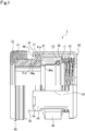
FIG. 1 is a front view showing a mechanical seal device held at holding length in a pre-use state (holding state) before the mechanical seal device is installed in the equipment in a first embodiment, the view including a cross sectional view in part; -
FIG. 2 is a front view showing the mechanical seal device held at use length in a use state where the mechanical seal device is installed in the equipment in the first embodiment, the view including a cross sectional view in part; -
FIG. 3 is a perspective view showing a mating ring of the first embodiment; -
FIG. 4 is a perspective view showing a case of the first embodiment; and -
FIG. 5 is a sectional view of a conventional mechanical seal device in the middle of attachment to devices. - Modes for implementing a mechanical seal device according to the present invention will be described based on an embodiment below. In the present embodiment, a rotating type mechanical seal device applied to an automobile air conditioning compressor that seals a carbon dioxide gas (CO2) serving as a coolant will be described.
- The mechanical seal device according to a first embodiment will be described with reference to
FIGS. 1 to 4 . Hereinafter, the left, right, upper, and lower sides on a paper plane ofFIG. 1 will be referred to as the left, right, upper, and lower sides, respectively, of the mechanical seal device in the following description. - As shown in
FIGS. 1 and2 , amechanical seal device 3 is installed between a housing 1 (equipment) of a compressor (equipment), and a shaft 2 (equipment, rotation shaft) arranged so as to pass through anaxial hole 11 of the housing 1 and communicate with an interior (equipment interior side) of the compressor and an exterior (atmosphere side). To theshaft 2, drive force from a crankshaft of an engine is transmitted via a mechanism such as an electromagnetic clutch (not shown) on the atmosphere side. Thereby, theshaft 2 is rotated so as to drive mechanisms in the interior (equipment interior side) of the compressor. - The
mechanical seal device 3 has amating ring 30 serving as a stationary side sealing ring installed in the housing 1 in a non-rotation state, and aseal ring 40 serving as a rotation side sealing ring installed on the side of theshaft 2, the seal ring to be rotated integrally with thisshaft 2. Themechanical seal device 3 also has acase 60, a coiled wave spring 70 (resilient member), aspring holder 71, and anO ring 80 as configurations for fitting theseal ring 40 to theshaft 2. - The
mating ring 30 and theseal ring 40 are arranged so as to face each other in the axial direction of theshaft 2. By closely attaching sealingfaces - A space on the outer peripheral side of the sealing faces 30a, 41a on the right side of the housing 1 is an equipment interior side space P to be filled with a carbon dioxide gas (CO2) serving as the sealed fluid. A space ranging from the inner peripheral side of the sealing faces 30a, 41a to the left side of the housing 1 is an atmosphere side (equipment exterior side) space A (
FIG. 2 ). - The end face of the
mating ring 30 on the side of theseal ring 40 is formed as the sealingface 30a to which the sealingface 41a of anannular sealing projection 41 serving as a sealing face of theseal ring 40 is slidably and closely attached. In an end part of themating ring 30 on the side of theseal ring 40, threeflanges 31 provided with threecutouts 32 are provided at equal intervals in the circumferential direction so as to extend outward in the radial direction (FIG. 3 ). - On an end face of the
seal ring 40 on the side of themating ring 30, theannular sealing projection 41 projecting in the direction of themating ring 30 is formed. The sealingface 41a of the sealingprojection 41 is slidably and closely attached to the sealingface 30a of themating ring 30. Theseal ring 40 is formed by for example a carbon sealing material, and themating ring 30 is formed by a hard sealing material having greater Young's modulus than the carbon sealing material (for example, ceramics such as SiC). - The
O ring 80 is installed in theseal ring 40 in a state where the O ring is accommodated in an O ring installment recessedsection 43 formed on an inner peripheral face of an end part of theseal ring 40 on the back face side (face on the opposite side to the mating ring 30). Thespring holder 71 which is a metal plate is abutted with and arranged in a back surface of theseal ring 40, and an inner diameter part thereof extends so as to close the back of the O ring installment recessedsection 43 of theseal ring 40. Thecase 60 which is a tripodal metal plate (for example, a stainless steel plate) is arranged on the back face side of thespring holder 71. - Referring to
FIG. 4 , thecase 60 is formed by a brim shapebottom plate 61 having afitting hole 62 in center, arib 63 slightly extending from thebottom plate 61 in the axial direction (shorter than the coiled wave spring 70), three guide pieces 64 (guide member) extending from therib 63 in the axial direction, and engagement projections 66 (engagement portions as holding means) on leading ends of theguide pieces 64. Theengagement projections 66 on the leading ends of theguide pieces 64 are formed by pressing theguide pieces 64 inward in the radial direction. By pressing, recessedsections 65 are formed on the opposite side to the projecting direction of theengagement projections 66. Theguide pieces 64 are formed at equal intervals in the circumferential direction, and engaged with cutouts 42 (FIG. 1 ) similarly formed on an outer peripheral face of theseal ring 40 at equal intervals. Thereby, theseal ring 40 is brought into a state where the seal ring is movable in the axial direction of theshaft 2 and into a state where the seal ring is immovable in the circumferential direction (rotating direction) (state where the seal ring is integrally rotated). - In order to assemble the
mechanical seal device 3 shown inFIG. 1 , the coiledwave spring 70, thespring holder 71, and theseal ring 40 in which theO ring 80 is installed are accommodated in thecase 60 in order. In this state, theguide pieces 64 of thecase 60 are matched with positions of thecutouts 32 of themating ring 30, and pushed into the axial direction (direction in which thebottom plate 61 of thecase 60 and themating ring 30 come close to each other) against resilient force of the coiledwave spring 70. By rotating thecase 60 by 60 degrees in the circumferential direction from a position where theengagement projections 66 exceed the flanges 31 (position where theengagement projections 66 and theflanges 31 are not overlapped when seen in the radial direction), engagement faces 66a (right faces) of theengagement projections 66 and engagedfaces 31a (left faces) of theflanges 31 are abutted with each other, so that the mechanical seal device is assembled. A state before themechanical seal device 3 shown inFIG. 1 is installed in the equipment is called as a holding state (or a pre-use state). - In a holding state, the engagement faces 66a of the
engagement projections 66 and the engaged faces 31a of theflanges 31 are abutted with each other, and the coiledwave spring 70 is interposed in a state where the coiledwave spring 70 is compressed at holding length in the axial direction. Thereby, theseal ring 40 is biased to themating ring 30 with holding pressure via thespring holder 71. That is, theseal ring 40 and themating ring 30 are resiliently held between the coiledwave spring 70 and theengagement projections 66. The holding length is shorter than natural length of the coiledwave spring 70 and longer than use length of the coiledwave spring 70 in a use state of themechanical seal device 3 shown inFIG. 2 . - Next, a use state where the
mechanical seal device 3 is installed in the equipment shown inFIG. 2 will be described. Themating ring 30 is fitted via agasket 50 into an annular recessedsection 12 formed by enlarging a diameter of an equipment interior side opening part of theaxial hole 11 of the housing 1. Thegasket 50 is formed by covering aninside metal ring 51 with arubber member 52 by insert molding. Theseal ring 40 is arranged on the equipment interior side of themating ring 30, and fitted via theO ring 80 to an outer peripheral face of theshaft 2 movably in the axial direction. - 1 By abutting an outer face (right face) of the
bottom plate 61 of thecase 60 with afirst step section 21 of theshaft 2, thecase 60 is locked in the axial direction of theshaft 2. Thecase 60 is formed in such a manner thatflat sections 62a of thefitting hole 62 are engaged withcutout sections 26 formed in part of thefirst step section 21 of the shaft 2 (FIG. 4 ). Thereby, the case is fitted to theshaft 2 immovably in the circumferential direction with respect to theshaft 2, that is, to be rotated integrally with theshaft 2 in accordance with rotation of theshaft 2. - In the
shaft 2, thefirst step section 21 in which thecutout sections 26 are formed is formed at a position to be engaged with theflat sections 62a of thecase 60, and asecond step section 22 is also formed at a position corresponding to an inner periphery of theseal ring 40. With thefirst step section 21 and thesecond step section 22 as borders, theshaft 2 is formed by asmall diameter section 23 which is a part on the atmosphere side of thefirst step section 21, the small diameter section being inserted into theaxial hole 11 of the housing 1 and an inner peripheral part of themating ring 30, amiddle diameter section 24 provided between thefirst step section 21 and thesecond step section 22, the second step section to which theseal ring 40 is fitted movably in the axial direction via theO ring 80, and alarge diameter section 25 on the equipment interior side of thesecond step section 22. Thereby, the inner most diameter of the sealing faces 30a, 41a of themating ring 30 and theseal ring 40 can be arranged on the inner diameter side of the innermost diameter of theseal ring 40 to which fluid pressure is applied, so that the mechanical seal device can be used as a balanced mechanical seal. The balanced mechanical seal indicates a mechanical seal in which a sealing face has an area of a part to which fluid pressure is not applied, so that a load of the fluid pressure to the sealing face can be reduced. (An unbalanced mechanical seal is another relating mechanical seal. This indicates a mechanical seal in which fluid pressure is applied to all over a sealing face, so that a load of the fluid pressure to the sealing face cannot be reduced.) - Axial length of the
mechanical seal device 3 is shorter in a use state shown inFIG. 2 than in a holding state shown inFIG. 1 by L. The axial length of themechanical seal device 3 is length between an outer end face of the gasket 50 (end face on the left side inFIGS. 1 and2 ) and an outer end face of the case 60 (end face on the right side inFIGS. 1 and2 ). Therefore, in a use state where themechanical seal device 3 is installed in the equipment, theseal ring 40 is biased from the coiledwave spring 70 to themating ring 30 with use pressure higher than holding pressure shown inFIG. 1 . In a state shown inFIG. 2 , themating ring 30 and thecase 60 are not engaged, so that the rotation of theshaft 2 is not prevented. - With such a configuration, bias force by the coiled
wave spring 70 is given to theseal ring 40 in the axial direction of theshaft 2, and the sealingface 41a on a leading end of the sealingprojection 41 is pushed onto the sealingface 30a of themating ring 30 with proper use pressure. Rotation torque from theshaft 2 is given to theseal ring 40 via thecase 60, so that the seal ring is rotated integrally with theshaft 2. As a result, in accordance with the rotation of theshaft 2, the sealingface 30a of themating ring 30 and the sealingface 41a of theseal ring 40 slide on each other in a closely attached state, and the sealed fluid is sealed by contact of the sealingface 30a of themating ring 30 and the sealingface 41a of theseal ring 40. - Not only in a use state where the
mechanical seal device 3 is installed in the equipment (FIG. 1 ) but also in a pre-use state before the mechanical seal device is installed in the equipment (FIG. 2 ), the axially perpendicular sealing faces 30a, 41a of both therings wave spring 70. Thus, grit and dust coming into a part between the sealingface 30a of themating ring 30 and the sealingface 41a of theseal ring 40 can be suppressed as far as possible. - The coiled
wave spring 70 used in a use state is used as a resilient member that holds the axially perpendicular sealing faces 30a, 41a of both therings - Movement of the
mating ring 30 upon receiving the resilient force of the coiledwave spring 70 can be inhibited by theengagement projections 66. Therefore, at the time of assembling into the equipment, only by moving thecase 60 upon receiving connection of therotation shaft 2 from the axial direction, themating ring 30 and theengagement projections 66 can be easily disengaged. - Between the
gasket 50 and theflanges 31, a favorable refuge place for theengagement projections 66 provided inward in the radial direction can be ensured. - The
flanges 31 and theengagement projections 66 can be detachably engaged by so-called bayonet engagement, and themating ring 30 and theseal ring 40 can be assembled into a resilient state (holding state) by a simple procedure. - In the
mechanical seal device 3, elements are integrated (unitized). Thus, handling is simplified and troublesomeness of a work at the time of installation and uninstallation can be resolved. - The
flanges 31 are provided in the non-rotatably fixedmating ring 30. Thus, a configuration of the axiallymovable seal ring 40 non-rotatably fixed to the rotation shaft is not complicated anymore. - The
guide pieces 64 are provided on the side of therotating seal ring 40, and theguide pieces 64 are positioned on the radially outer side of the sealing faces 30a, 41a of themating ring 30 and theseal ring 40. Therefore, at the time of use, a circumferential flow in accordance with rotation of theguide pieces 64 is generated on the outer side of the sealing faces 30a, 41a. The circumferential flow becomes a so-called fluid curtain, so that a radical pressure change of the sealed fluid or the like can be suppressed from acting on the sealing faces 30a, 41a. - The embodiment of the present invention is described above with the drawings. However, specific configurations are not limited to the embodiment but modifications and additions that are made within the range not departing from the gist of the present invention are also included in the present invention.
- For example, in the above embodiment, the rotating type mechanical seal device is described as the
mechanical seal device 3. However, a stationary type mechanical seal device may be adopted. For example, engaged sections such as flanges may be provided on the side of a mating ring non-rotatably fixed to a rotation shaft, and engagement sections to be engaged with the engaged sections may be provided on the side of a seal ring fixed to a housing via a spring. In this case, since guide pieces on the rotation side can be shortened, the rotation side can be downsized. - As a holding member that resiliently holds the
seal ring 40 and themating ring 30, theengagement projections 66 provided in theguide pieces 64 of thecase 60 are described as an example. However, the holding member is not necessarily provided in thecase 60. The point is, a member that resiliently holds theseal ring 40 and themating ring 30 is required, and the member may be for example clips attachable and detachable from an exterior. In this case, the clips may be detached in the middle of assembling into the equipment or at the time of assembling. - The mechanical seal device may include a mating ring having an axially perpendicular sealing face, an axially movable seal ring having an axially perpendicular sealing face to be brought into contact with the sealing face of the mating ring, a guide member that guides the seal ring in the axial direction, and a resilient member that presses the seal ring to the side of the mating ring, and the seal ring and the mating ring may be resiliently held between the resilient member and a holding means. Not only in a use state where the mechanical seal device is installed in the equipment but also in a pre-use state before the mechanical seal device is installed in the equipment, the axially perpendicular sealing faces of both the rings are in contact with each other with pressure based on resilient force of the resilient member. Thus, grit and dust coming into a part between the sealing face of the mating ring and the sealing face of the seal ring can be suppressed as far as possible.
- A case where the equipment in which the
mechanical seal device 3 is used is an automobile air conditioning compressor is described above. However, the mechanical seal device may be used in any kind of equipment. -
- 1
- Housing (equipment)
- 2
- Shaft (equipment, rotation shaft)
- 3
- Mechanical seal device
- 30
- Mating ring
- 30a
- Sealing face
- 31
- Flange
- 32
- Cutout part
- 40
- Seal ring
- 41
- Sealing projection
- 41a
- Sealing face
- 60
- Case
- 61
- Bottom plate
- 63
- Rib
- 64
- Guide piece (guide member)
- 66
- Engagement projection (engagement portion)
- 66a
- Engagement face
- 70
- Coiled wave spring (resilient member)
- A
- Atmosphere side space
- P
- Device interior side space
Claims (5)
- A mechanical seal device comprising:a mating ring having an axially perpendicular sealing face and having a flange projecting in a radial direction;an axially movable seal ring having an axially perpendicular sealing face to be brought into contact with the sealing face of the mating ring;a resilient member that presses the seal ring to a side of the mating ring; anda case inside which the seal ring and the resilient member are accommodated, characterized in that:a fluid is sealed by bringing the axially perpendicular sealing faces of both the rings into contact with each other and relatively rotating the sealing faces; andby engaging the case and the flange of the mating ring with each other, the seal ring and the mating ring are resiliently held.
- The mechanical seal device as set forth in claim 1, characterized in that:the case has a guide piece projecting on the side of the mating ring in the axial direction;the seal ring has a cutout on an outer face; andby engaging the guide piece with the cutout, the seal ring is incapable of being relatively rotated with respect to the case.
- The mechanical seal device as set forth in claim 2, characterized in that:
the guide piece has an engagement portion projecting in the radial direction, and is resiliently held by engaging the engagement portion with the flange of the mating ring. - The mechanical seal device as set forth in claim 3, characterized in that:in the flange, a cutout having such width that the engagement portion is capable of passing through is formed in a circumferential direction of the flange.
- The mechanical seal device as set forth in any of claims 1 to 4, characterized in that:
when the case is connected to a rotation shaft, the flange and the case are disengaged from each other.
Applications Claiming Priority (2)
| Application Number | Priority Date | Filing Date | Title |
|---|---|---|---|
| JP2014243129 | 2014-12-01 | ||
| PCT/JP2015/083321 WO2016088659A1 (en) | 2014-12-01 | 2015-11-27 | Mechanical seal apparatus |
Publications (3)
| Publication Number | Publication Date |
|---|---|
| EP3228907A1 true EP3228907A1 (en) | 2017-10-11 |
| EP3228907A4 EP3228907A4 (en) | 2018-08-08 |
| EP3228907B1 EP3228907B1 (en) | 2020-11-18 |
Family
ID=56091604
Family Applications (1)
| Application Number | Title | Priority Date | Filing Date |
|---|---|---|---|
| EP15865795.7A Active EP3228907B1 (en) | 2014-12-01 | 2015-11-27 | Mechanical seal apparatus |
Country Status (3)
| Country | Link |
|---|---|
| EP (1) | EP3228907B1 (en) |
| JP (1) | JP6573631B2 (en) |
| WO (1) | WO2016088659A1 (en) |
Cited By (1)
| Publication number | Priority date | Publication date | Assignee | Title |
|---|---|---|---|---|
| US12060944B2 (en) | 2020-06-23 | 2024-08-13 | Eagle Industry Co., Ltd. | Mechanical seal |
Families Citing this family (22)
| Publication number | Priority date | Publication date | Assignee | Title |
|---|---|---|---|---|
| US10354325B1 (en) | 2013-06-28 | 2019-07-16 | Winklevoss Ip, Llc | Computer-generated graphical user interface |
| US10269009B1 (en) | 2013-06-28 | 2019-04-23 | Winklevoss Ip, Llc | Systems, methods, and program products for a digital math-based asset exchange |
| US9898782B1 (en) | 2013-06-28 | 2018-02-20 | Winklevoss Ip, Llc | Systems, methods, and program products for operating exchange traded products holding digital math-based assets |
| US10068228B1 (en) | 2013-06-28 | 2018-09-04 | Winklevoss Ip, Llc | Systems and methods for storing digital math-based assets using a secure portal |
| US9853977B1 (en) | 2015-01-26 | 2017-12-26 | Winklevoss Ip, Llc | System, method, and program product for processing secure transactions within a cloud computing system |
| US10915891B1 (en) | 2015-03-16 | 2021-02-09 | Winklevoss Ip, Llc | Autonomous devices |
| US10158480B1 (en) | 2015-03-16 | 2018-12-18 | Winklevoss Ip, Llc | Autonomous devices |
| US10540654B1 (en) | 2018-02-12 | 2020-01-21 | Winklevoss Ip, Llc | System, method and program product for generating and utilizing stable value digital assets |
| US10929842B1 (en) | 2018-03-05 | 2021-02-23 | Winklevoss Ip, Llc | System, method and program product for depositing and withdrawing stable value digital assets in exchange for fiat |
| US12271898B1 (en) | 2018-03-05 | 2025-04-08 | Gemini Ip, Llc | System, method and program product for modifying a supply of stable value digital asset tokens |
| US11200569B1 (en) | 2018-02-12 | 2021-12-14 | Winklevoss Ip, Llc | System, method and program product for making payments using fiat-backed digital assets |
| US10438290B1 (en) | 2018-03-05 | 2019-10-08 | Winklevoss Ip, Llc | System, method and program product for generating and utilizing stable value digital assets |
| US11308487B1 (en) | 2018-02-12 | 2022-04-19 | Gemini Ip, Llc | System, method and program product for obtaining digital assets |
| US11139955B1 (en) | 2018-02-12 | 2021-10-05 | Winklevoss Ip, Llc | Systems, methods, and program products for loaning digital assets and for depositing, holding and/or distributing collateral as a token in the form of digital assets on an underlying blockchain |
| US12141871B1 (en) | 2018-02-12 | 2024-11-12 | Gemini Ip, Llc | System, method and program product for generating and utilizing stable value digital assets |
| US10373158B1 (en) | 2018-02-12 | 2019-08-06 | Winklevoss Ip, Llc | System, method and program product for modifying a supply of stable value digital asset tokens |
| US11522700B1 (en) | 2018-02-12 | 2022-12-06 | Gemini Ip, Llc | Systems, methods, and program products for depositing, holding and/or distributing collateral as a token in the form of digital assets on an underlying blockchain |
| US11334883B1 (en) | 2018-03-05 | 2022-05-17 | Gemini Ip, Llc | Systems, methods, and program products for modifying the supply, depositing, holding and/or distributing collateral as a stable value token in the form of digital assets |
| US11475442B1 (en) | 2018-02-12 | 2022-10-18 | Gemini Ip, Llc | System, method and program product for modifying a supply of stable value digital asset tokens |
| US10373129B1 (en) | 2018-03-05 | 2019-08-06 | Winklevoss Ip, Llc | System, method and program product for generating and utilizing stable value digital assets |
| US11501370B1 (en) | 2019-06-17 | 2022-11-15 | Gemini Ip, Llc | Systems, methods, and program products for non-custodial trading of digital assets on a digital asset exchange |
| US11346449B2 (en) * | 2020-01-23 | 2022-05-31 | Kaydon Ring & Seal, Inc. | Self-centering seal component for high speed shaft assemblies |
Family Cites Families (7)
| Publication number | Priority date | Publication date | Assignee | Title |
|---|---|---|---|---|
| DE2500098A1 (en) * | 1975-01-03 | 1976-07-08 | Goetzewerke | MECHANICAL RING, IN PARTICULAR COUNTER RING FOR MECHANICAL SEALS |
| DE3248074C2 (en) * | 1982-12-24 | 1985-10-17 | Goetze Ag, 5093 Burscheid | Sealing unit for, in particular, liquid pumps |
| GB8528261D0 (en) * | 1985-11-15 | 1985-12-18 | Burgess Eng Ltd G N | Sealing device |
| US6322079B1 (en) * | 1999-10-19 | 2001-11-27 | Perkinelmer, Inc. | Face seal |
| EP1213516A1 (en) * | 2000-12-08 | 2002-06-12 | M.E.F. Financing Establishment | Mechanical seal |
| US7997583B2 (en) * | 2005-11-08 | 2011-08-16 | Eagle Industry Co., Ltd. | Mechanical sealing device |
| US8181966B2 (en) * | 2009-01-12 | 2012-05-22 | Kaydon Ring & Seal, Inc. | Gas seal for aerospace engines and the like |
-
2015
- 2015-11-27 JP JP2016562414A patent/JP6573631B2/en not_active Expired - Fee Related
- 2015-11-27 EP EP15865795.7A patent/EP3228907B1/en active Active
- 2015-11-27 WO PCT/JP2015/083321 patent/WO2016088659A1/en not_active Ceased
Cited By (1)
| Publication number | Priority date | Publication date | Assignee | Title |
|---|---|---|---|---|
| US12060944B2 (en) | 2020-06-23 | 2024-08-13 | Eagle Industry Co., Ltd. | Mechanical seal |
Also Published As
| Publication number | Publication date |
|---|---|
| EP3228907A4 (en) | 2018-08-08 |
| WO2016088659A1 (en) | 2016-06-09 |
| JPWO2016088659A1 (en) | 2017-09-07 |
| JP6573631B2 (en) | 2019-09-11 |
| EP3228907B1 (en) | 2020-11-18 |
Similar Documents
| Publication | Publication Date | Title |
|---|---|---|
| EP3228907B1 (en) | Mechanical seal apparatus | |
| EP2878827B1 (en) | Gas blower | |
| EP3184864B1 (en) | Sealing structure | |
| EP3222891B1 (en) | Sealing structure | |
| EP3376078B1 (en) | Mechanical seal | |
| JPWO2014030742A1 (en) | Sealing device | |
| JP6328658B2 (en) | mechanical seal | |
| CN111094814B (en) | Mechanical sealing element | |
| US11549589B2 (en) | Mechanical seal | |
| JP2021099160A (en) | Radial shaft seal, bellows flange, and attaching method thereof | |
| CN103109075A (en) | Starting device and method for producing a stop for a pinion, which is arranged displaceably on a shaft, of a starting device | |
| JP6612092B2 (en) | mechanical seal | |
| CN105679608B (en) | Electromagnetic switch and vehicle starter | |
| EP1530002B1 (en) | Valve for containers of pressurized fluids with dirt blocking device | |
| JP2008256138A (en) | Bearing device | |
| US11105423B2 (en) | Mechanical sealing device | |
| US10378592B2 (en) | Shaft-hub connection | |
| JP6218556B2 (en) | mechanical seal | |
| JPH0227724Y2 (en) | ||
| JP2017215031A (en) | Mechanical seal device | |
| JP6823559B2 (en) | Shaft sealing device | |
| JP2007321784A (en) | Sealing device | |
| CN112739894A (en) | Mounting structure of horn mouth | |
| JP2018204717A (en) | Dust seal structure | |
| CN110612401A (en) | slave cylinder |
Legal Events
| Date | Code | Title | Description |
|---|---|---|---|
| STAA | Information on the status of an ep patent application or granted ep patent |
Free format text: STATUS: THE INTERNATIONAL PUBLICATION HAS BEEN MADE |
|
| PUAI | Public reference made under article 153(3) epc to a published international application that has entered the european phase |
Free format text: ORIGINAL CODE: 0009012 |
|
| STAA | Information on the status of an ep patent application or granted ep patent |
Free format text: STATUS: REQUEST FOR EXAMINATION WAS MADE |
|
| 17P | Request for examination filed |
Effective date: 20170629 |
|
| AK | Designated contracting states |
Kind code of ref document: A1 Designated state(s): AL AT BE BG CH CY CZ DE DK EE ES FI FR GB GR HR HU IE IS IT LI LT LU LV MC MK MT NL NO PL PT RO RS SE SI SK SM TR |
|
| AX | Request for extension of the european patent |
Extension state: BA ME |
|
| DAV | Request for validation of the european patent (deleted) | ||
| DAX | Request for extension of the european patent (deleted) | ||
| A4 | Supplementary search report drawn up and despatched |
Effective date: 20180711 |
|
| RIC1 | Information provided on ipc code assigned before grant |
Ipc: F16J 15/34 20060101AFI20180705BHEP |
|
| GRAP | Despatch of communication of intention to grant a patent |
Free format text: ORIGINAL CODE: EPIDOSNIGR1 |
|
| STAA | Information on the status of an ep patent application or granted ep patent |
Free format text: STATUS: GRANT OF PATENT IS INTENDED |
|
| INTG | Intention to grant announced |
Effective date: 20200609 |
|
| GRAS | Grant fee paid |
Free format text: ORIGINAL CODE: EPIDOSNIGR3 |
|
| GRAA | (expected) grant |
Free format text: ORIGINAL CODE: 0009210 |
|
| STAA | Information on the status of an ep patent application or granted ep patent |
Free format text: STATUS: THE PATENT HAS BEEN GRANTED |
|
| RAP1 | Party data changed (applicant data changed or rights of an application transferred) |
Owner name: EAGLE INDUSTRY CO., LTD. |
|
| AK | Designated contracting states |
Kind code of ref document: B1 Designated state(s): AL AT BE BG CH CY CZ DE DK EE ES FI FR GB GR HR HU IE IS IT LI LT LU LV MC MK MT NL NO PL PT RO RS SE SI SK SM TR |
|
| REG | Reference to a national code |
Ref country code: GB Ref legal event code: FG4D |
|
| REG | Reference to a national code |
Ref country code: CH Ref legal event code: EP |
|
| REG | Reference to a national code |
Ref country code: IE Ref legal event code: FG4D |
|
| REG | Reference to a national code |
Ref country code: DE Ref legal event code: R096 Ref document number: 602015062327 Country of ref document: DE |
|
| REG | Reference to a national code |
Ref country code: AT Ref legal event code: REF Ref document number: 1336135 Country of ref document: AT Kind code of ref document: T Effective date: 20201215 |
|
| REG | Reference to a national code |
Ref country code: AT Ref legal event code: MK05 Ref document number: 1336135 Country of ref document: AT Kind code of ref document: T Effective date: 20201118 |
|
| REG | Reference to a national code |
Ref country code: NL Ref legal event code: MP Effective date: 20201118 |
|
| PG25 | Lapsed in a contracting state [announced via postgrant information from national office to epo] |
Ref country code: GR Free format text: LAPSE BECAUSE OF FAILURE TO SUBMIT A TRANSLATION OF THE DESCRIPTION OR TO PAY THE FEE WITHIN THE PRESCRIBED TIME-LIMIT Effective date: 20210219 Ref country code: NO Free format text: LAPSE BECAUSE OF FAILURE TO SUBMIT A TRANSLATION OF THE DESCRIPTION OR TO PAY THE FEE WITHIN THE PRESCRIBED TIME-LIMIT Effective date: 20210218 Ref country code: FI Free format text: LAPSE BECAUSE OF FAILURE TO SUBMIT A TRANSLATION OF THE DESCRIPTION OR TO PAY THE FEE WITHIN THE PRESCRIBED TIME-LIMIT Effective date: 20201118 Ref country code: RS Free format text: LAPSE BECAUSE OF FAILURE TO SUBMIT A TRANSLATION OF THE DESCRIPTION OR TO PAY THE FEE WITHIN THE PRESCRIBED TIME-LIMIT Effective date: 20201118 Ref country code: PT Free format text: LAPSE BECAUSE OF FAILURE TO SUBMIT A TRANSLATION OF THE DESCRIPTION OR TO PAY THE FEE WITHIN THE PRESCRIBED TIME-LIMIT Effective date: 20210318 |
|
| PG25 | Lapsed in a contracting state [announced via postgrant information from national office to epo] |
Ref country code: AT Free format text: LAPSE BECAUSE OF FAILURE TO SUBMIT A TRANSLATION OF THE DESCRIPTION OR TO PAY THE FEE WITHIN THE PRESCRIBED TIME-LIMIT Effective date: 20201118 Ref country code: BG Free format text: LAPSE BECAUSE OF FAILURE TO SUBMIT A TRANSLATION OF THE DESCRIPTION OR TO PAY THE FEE WITHIN THE PRESCRIBED TIME-LIMIT Effective date: 20210218 Ref country code: IS Free format text: LAPSE BECAUSE OF FAILURE TO SUBMIT A TRANSLATION OF THE DESCRIPTION OR TO PAY THE FEE WITHIN THE PRESCRIBED TIME-LIMIT Effective date: 20210318 Ref country code: SE Free format text: LAPSE BECAUSE OF FAILURE TO SUBMIT A TRANSLATION OF THE DESCRIPTION OR TO PAY THE FEE WITHIN THE PRESCRIBED TIME-LIMIT Effective date: 20201118 Ref country code: PL Free format text: LAPSE BECAUSE OF FAILURE TO SUBMIT A TRANSLATION OF THE DESCRIPTION OR TO PAY THE FEE WITHIN THE PRESCRIBED TIME-LIMIT Effective date: 20201118 Ref country code: LV Free format text: LAPSE BECAUSE OF FAILURE TO SUBMIT A TRANSLATION OF THE DESCRIPTION OR TO PAY THE FEE WITHIN THE PRESCRIBED TIME-LIMIT Effective date: 20201118 |
|
| REG | Reference to a national code |
Ref country code: LT Ref legal event code: MG9D |
|
| PG25 | Lapsed in a contracting state [announced via postgrant information from national office to epo] |
Ref country code: HR Free format text: LAPSE BECAUSE OF FAILURE TO SUBMIT A TRANSLATION OF THE DESCRIPTION OR TO PAY THE FEE WITHIN THE PRESCRIBED TIME-LIMIT Effective date: 20201118 |
|
| REG | Reference to a national code |
Ref country code: CH Ref legal event code: PL |
|
| PG25 | Lapsed in a contracting state [announced via postgrant information from national office to epo] |
Ref country code: SK Free format text: LAPSE BECAUSE OF FAILURE TO SUBMIT A TRANSLATION OF THE DESCRIPTION OR TO PAY THE FEE WITHIN THE PRESCRIBED TIME-LIMIT Effective date: 20201118 Ref country code: RO Free format text: LAPSE BECAUSE OF FAILURE TO SUBMIT A TRANSLATION OF THE DESCRIPTION OR TO PAY THE FEE WITHIN THE PRESCRIBED TIME-LIMIT Effective date: 20201118 Ref country code: EE Free format text: LAPSE BECAUSE OF FAILURE TO SUBMIT A TRANSLATION OF THE DESCRIPTION OR TO PAY THE FEE WITHIN THE PRESCRIBED TIME-LIMIT Effective date: 20201118 Ref country code: CZ Free format text: LAPSE BECAUSE OF FAILURE TO SUBMIT A TRANSLATION OF THE DESCRIPTION OR TO PAY THE FEE WITHIN THE PRESCRIBED TIME-LIMIT Effective date: 20201118 Ref country code: LU Free format text: LAPSE BECAUSE OF NON-PAYMENT OF DUE FEES Effective date: 20201127 Ref country code: LT Free format text: LAPSE BECAUSE OF FAILURE TO SUBMIT A TRANSLATION OF THE DESCRIPTION OR TO PAY THE FEE WITHIN THE PRESCRIBED TIME-LIMIT Effective date: 20201118 Ref country code: SM Free format text: LAPSE BECAUSE OF FAILURE TO SUBMIT A TRANSLATION OF THE DESCRIPTION OR TO PAY THE FEE WITHIN THE PRESCRIBED TIME-LIMIT Effective date: 20201118 |
|
| REG | Reference to a national code |
Ref country code: BE Ref legal event code: MM Effective date: 20201130 |
|
| REG | Reference to a national code |
Ref country code: DE Ref legal event code: R097 Ref document number: 602015062327 Country of ref document: DE |
|
| PG25 | Lapsed in a contracting state [announced via postgrant information from national office to epo] |
Ref country code: LI Free format text: LAPSE BECAUSE OF NON-PAYMENT OF DUE FEES Effective date: 20201130 Ref country code: CH Free format text: LAPSE BECAUSE OF NON-PAYMENT OF DUE FEES Effective date: 20201130 Ref country code: DK Free format text: LAPSE BECAUSE OF FAILURE TO SUBMIT A TRANSLATION OF THE DESCRIPTION OR TO PAY THE FEE WITHIN THE PRESCRIBED TIME-LIMIT Effective date: 20201118 Ref country code: MC Free format text: LAPSE BECAUSE OF FAILURE TO SUBMIT A TRANSLATION OF THE DESCRIPTION OR TO PAY THE FEE WITHIN THE PRESCRIBED TIME-LIMIT Effective date: 20201118 |
|
| PLBE | No opposition filed within time limit |
Free format text: ORIGINAL CODE: 0009261 |
|
| STAA | Information on the status of an ep patent application or granted ep patent |
Free format text: STATUS: NO OPPOSITION FILED WITHIN TIME LIMIT |
|
| 26N | No opposition filed |
Effective date: 20210819 |
|
| GBPC | Gb: european patent ceased through non-payment of renewal fee |
Effective date: 20210218 |
|
| PG25 | Lapsed in a contracting state [announced via postgrant information from national office to epo] |
Ref country code: AL Free format text: LAPSE BECAUSE OF FAILURE TO SUBMIT A TRANSLATION OF THE DESCRIPTION OR TO PAY THE FEE WITHIN THE PRESCRIBED TIME-LIMIT Effective date: 20201118 Ref country code: IE Free format text: LAPSE BECAUSE OF NON-PAYMENT OF DUE FEES Effective date: 20201127 Ref country code: IT Free format text: LAPSE BECAUSE OF FAILURE TO SUBMIT A TRANSLATION OF THE DESCRIPTION OR TO PAY THE FEE WITHIN THE PRESCRIBED TIME-LIMIT Effective date: 20201118 Ref country code: FR Free format text: LAPSE BECAUSE OF NON-PAYMENT OF DUE FEES Effective date: 20210118 Ref country code: NL Free format text: LAPSE BECAUSE OF FAILURE TO SUBMIT A TRANSLATION OF THE DESCRIPTION OR TO PAY THE FEE WITHIN THE PRESCRIBED TIME-LIMIT Effective date: 20201118 |
|
| PG25 | Lapsed in a contracting state [announced via postgrant information from national office to epo] |
Ref country code: SI Free format text: LAPSE BECAUSE OF FAILURE TO SUBMIT A TRANSLATION OF THE DESCRIPTION OR TO PAY THE FEE WITHIN THE PRESCRIBED TIME-LIMIT Effective date: 20201118 |
|
| PG25 | Lapsed in a contracting state [announced via postgrant information from national office to epo] |
Ref country code: ES Free format text: LAPSE BECAUSE OF FAILURE TO SUBMIT A TRANSLATION OF THE DESCRIPTION OR TO PAY THE FEE WITHIN THE PRESCRIBED TIME-LIMIT Effective date: 20201118 Ref country code: GB Free format text: LAPSE BECAUSE OF NON-PAYMENT OF DUE FEES Effective date: 20210218 |
|
| PG25 | Lapsed in a contracting state [announced via postgrant information from national office to epo] |
Ref country code: IS Free format text: LAPSE BECAUSE OF FAILURE TO SUBMIT A TRANSLATION OF THE DESCRIPTION OR TO PAY THE FEE WITHIN THE PRESCRIBED TIME-LIMIT Effective date: 20210318 Ref country code: TR Free format text: LAPSE BECAUSE OF FAILURE TO SUBMIT A TRANSLATION OF THE DESCRIPTION OR TO PAY THE FEE WITHIN THE PRESCRIBED TIME-LIMIT Effective date: 20201118 Ref country code: MT Free format text: LAPSE BECAUSE OF FAILURE TO SUBMIT A TRANSLATION OF THE DESCRIPTION OR TO PAY THE FEE WITHIN THE PRESCRIBED TIME-LIMIT Effective date: 20201118 Ref country code: CY Free format text: LAPSE BECAUSE OF FAILURE TO SUBMIT A TRANSLATION OF THE DESCRIPTION OR TO PAY THE FEE WITHIN THE PRESCRIBED TIME-LIMIT Effective date: 20201118 |
|
| PG25 | Lapsed in a contracting state [announced via postgrant information from national office to epo] |
Ref country code: MK Free format text: LAPSE BECAUSE OF FAILURE TO SUBMIT A TRANSLATION OF THE DESCRIPTION OR TO PAY THE FEE WITHIN THE PRESCRIBED TIME-LIMIT Effective date: 20201118 |
|
| PG25 | Lapsed in a contracting state [announced via postgrant information from national office to epo] |
Ref country code: BE Free format text: LAPSE BECAUSE OF NON-PAYMENT OF DUE FEES Effective date: 20201130 |
|
| P01 | Opt-out of the competence of the unified patent court (upc) registered |
Effective date: 20230514 |
|
| P02 | Opt-out of the competence of the unified patent court (upc) changed |
Effective date: 20230516 |
|
| P04 | Withdrawal of opt-out of the competence of the unified patent court (upc) registered |
Effective date: 20230612 |
|
| PGFP | Annual fee paid to national office [announced via postgrant information from national office to epo] |
Ref country code: DE Payment date: 20250930 Year of fee payment: 11 |