EP3228751B1 - Support for e.g. road and traffic signs - Google Patents
Support for e.g. road and traffic signs Download PDFInfo
- Publication number
- EP3228751B1 EP3228751B1 EP17164155.8A EP17164155A EP3228751B1 EP 3228751 B1 EP3228751 B1 EP 3228751B1 EP 17164155 A EP17164155 A EP 17164155A EP 3228751 B1 EP3228751 B1 EP 3228751B1
- Authority
- EP
- European Patent Office
- Prior art keywords
- support
- parts
- aperture
- support according
- male
- Prior art date
- Legal status (The legal status is an assumption and is not a legal conclusion. Google has not performed a legal analysis and makes no representation as to the accuracy of the status listed.)
- Active
Links
Images


Classifications
-
- E—FIXED CONSTRUCTIONS
- E01—CONSTRUCTION OF ROADS, RAILWAYS, OR BRIDGES
- E01F—ADDITIONAL WORK, SUCH AS EQUIPPING ROADS OR THE CONSTRUCTION OF PLATFORMS, HELICOPTER LANDING STAGES, SIGNS, SNOW FENCES, OR THE LIKE
- E01F9/00—Arrangement of road signs or traffic signals; Arrangements for enforcing caution
- E01F9/60—Upright bodies, e.g. marker posts or bollards; Supports for road signs
- E01F9/688—Free-standing bodies
- E01F9/692—Portable base members therefor
-
- E—FIXED CONSTRUCTIONS
- E04—BUILDING
- E04H—BUILDINGS OR LIKE STRUCTURES FOR PARTICULAR PURPOSES; SWIMMING OR SPLASH BATHS OR POOLS; MASTS; FENCING; TENTS OR CANOPIES, IN GENERAL
- E04H12/00—Towers; Masts or poles; Chimney stacks; Water-towers; Methods of erecting such structures
- E04H12/22—Sockets or holders for poles or posts
- E04H12/2238—Sockets or holders for poles or posts to be placed on the ground
Definitions
- the present invention relates to a support for e.g. road and traffic signs, where the support comprises at least a first upper surface and a second lower surface, where the support further is divided into at least two individual parts, a first part and a second part with an assembly surface, where the first part and the second parts are complementary to each other, where the first part makes up most of the second lower surface and the second part makes up most of the first upper surface and, where the first part and the second part comprise interlocking means, configured for locking the first part and the second part in relation to each other in a first direction X and a second direction Y.
- supports for different objects which may be used as temporary signage or markings, e.g. during roadwork.
- supports for separation fences e.g. at construction sites and events.
- Known supports made in one piece typically hold a weight of 25 to 30 kg. Due to the weight and form of the support it then constitutes a stable base.
- US 2007/241255 A discloses an example of a known support.
- the sign post support e.g. for road and traffic signs, comprises at least two-parts, a first lower part having a plate shape and a holding member for the sign post.
- One or more second upper stackable plates are arranged on top of the first lower part. The lowermost of the upper parts is screwed together with the lower part and the holding member extends through a hole in the upper plate member(s) to allow insertion of the sign post.
- a support which comprises a first part and a second part complementary to each other, and where a pin fits in a hole, holding the support in a first direction X and a second direction Y.
- the support which is intended for fences, is assembled just by putting one part on top of another, where holding means in terms of pins and holes will keep the parts together.
- the support does not comprise interlocking means so if it is hit by a car and tips over it will disassemble.
- the object of this invention is therefore to provide a support of the type mentioned in the introduction which does not create problems when it needs to be handled during setup and relocation and, hence, where the supports are better than prior-art technology.
- the above object is achieved with a support of the type mentioned in the introduction, for e.g. road and traffic signs, where the support comprises at least a first upper surface and a second lower surface, where the support further is divided into at least two individual parts, a first part and a second part with an assembly surface, where the first part and the second parts are complementary to each other, where the first part makes up most of the second lower surface and the second part makes up most of the first upper surface and, where the first part and the second part comprise interlocking means, configured for locking the first part and the second part in relation to each other in a first direction X and a second direction Y, where each of the first and second parts comprise first interlocking means which first interlocking means comprise at least a male element and at least a corresponding female element, which male and female parts extend substantially parallel with the first upper and the second lower surfaces, configured for locking the support parts relative to each other in the first direction X, and, where the interlocking means also comprise second interlocking means which
- first part and a second part where the two parts are designed to fit together.
- the support Being at least two-parted the support is also easier to handle than a one-parted support with the same weight, as the two-parted support can be handled one part at a time. Handling the parts one after the other therefore makes the support more user-friendly to handle, as the personnel who have to move and handle the supports are now able to handle a lower weight at a time, and still comply with known rules and regulations concerning traffic regulations.
- the support is rectangular or a parallelogram in shape, having at least a first surface and a second surface, a first side and a second side, a first end and a second end.
- the support is circular or oval in shape having at least a first surface and a second surface.
- the support is square, rhombus or trapezium in shape having at least a first surface and a second surface, a first side, a second side, a third side and a fourth side.
- the two parts comprise at least one male element or female element which is able to mesh with a corresponding female element or male element at the other part
- the female elements could be e.g. holes, apertures, missing parts or openings in the support with concave shape
- the male elements could be e.g. pins, sticks or other devices with convex shape.
- the support is thus locked in a second direction Y.
- the parts are designed to fit together, so that the two parts easily and freely slide together when one part is placed interacting with the other part.
- the support is in fact locked and secured in all the directions X, Y and Z, when the support is moved in a straight line, being a linear movement.
- the support is placed on a surface and the second part of the support is moved as part of a rotation around the X-axis, the support is able to be opened and the parts thus separated.
- the interlocking means also comprise hook elements along the assembly surface where the free end of the first part is complementary to an intermediate part of the second part and where the free end of the second part is complementary with an intermediate part of the first part, where there is no difference in the thickness between the free ends and the intermediate parts of the first part and second part, respectively.
- the first part and the second part do not have to have the same thickness.
- the present invention also relates to a support for e.g. road and traffic signs, where the first part and the second part of the support each further comprise first carry- and handling means.
- the weight of the first part and the second part is less than the weight of the total support. That means that the personnel are exposed to a lower load by using the carry- and handling means of the individual part.
- the carry- and handling means are at the first part and/or the second part in the form of a handlebar.
- the handlebar is placed at a side of at least one of the parts.
- an ergonomic handle which is to facilitate the transportation of the part in vertical position.
- the carry- and handling means are recess formed underneath at least one of the two parts.
- the recess makes it possible to facilitate the handling of the part when the part is in a horizontal position.
- the support further comprises carry- and handling means accessible from the third side and the second surface as well as from the fourth side and the second surface.
- the carry- and handling means for example in the form of apertures, further makes it possible to facilitate the handling of the part or the whole support, when the part is in a horizontal position.
- the carry- and handling means could be used for manual handling as well as handling by means of a tool, a special carriage, special vehicle, etc.
- the present invention also relates to a support for e.g. road and traffic signs, where the support comprises stackable means.
- the support is provided with stackable portions provided at the first surface and stackable portions provided at the second surface. It is thus possible, with enough stackable means and in a size suitable to the size and weight of the support, to have a stable solution which enables less space when stored or transported.
- the present invention also relates to a support for e.g. road and traffic signs, where the stackable means are arranged at the first upper surface and the second lower surface and that the stackable means comprise male portions and female portions , respectively.
- the support is provided with raised portions, male portions, at the first surface.
- the male portions fit the lowered portions, the female portions, provided at the second surface.
- the support is provided with raised portions, male portions, at the second surface.
- the male portions fit the lowered portions, the female portions, provided at the first surface.
- the support is provided with male portions and female portions at the second surface. The male portions then fit the female portions and the female portions then fit the male portions provided at the first surface.
- the present invention also relates to a support for e.g. road and traffic signs, where the second surface further comprises a number of male contact portions.
- the present invention also relates to a support for e.g. road and traffic signs, where the support comprises at least one aperture configured for receipt of posts for e.g. road and traffic signs, where the at least one aperture extends from the first surface towards the second surface.
- the support is provided with a variety of apertures with different dimensions. Different dimensions of apertures are thus supplementing each other and making the use of the support more flexible.
- the apertures are acting as drain holes, which makes it possible to drain water from the support and hence to avoid damages of the support which may occur due to frost, when the support is used in cold environments.
- the drain apertures are configured to drain water away from the assembly surface between the two parts, thereby also minimizing the risk of them sticking together at temperatures below 0 degree Celsius.
- the present invention also relates to a support for e.g. road and traffic signs, where at least one aperture is substantially perpendicular to the second surface.
- the present invention also relates to a support for e.g. road and traffic signs, where the at least one aperture extends through the support.
- the present invention also relates to a support for e.g. road and traffic signs, where the support at least further comprises a first end side, where the first side is at least partly slanted from an outer position at the second surface and in the direction towards an inner position of the first surface.
- the support has at least a first surface and a second surface, a first side or a first end and a second side or a second end, a third side and a fourth side.
- the present invention also relates to a support for e.g. road and traffic signs, where at least one aperture in the first part is aligned with an aperture in the second part when the first and second parts are assembled into the support.
- the present invention also relates to a support for e.g. road and traffic signs, where the support further comprises at least a hole prepared for mounting and securing the support.
- the present invention also relates to a support for e.g. road and traffic signs, where the support is shatterproof.
- the assembly surface is divided into zones in order to minimize the assembly surface, which is done for the same reason as the drain aperture in general, this could be holes of any form, shape and dimension.
- the present invention also relates to a support for e.g. road and traffic signs, where the first support part further comprises second carry- and handling means arranged between the second lower surface and the third side as well as between the second lower surface and the fourth side.
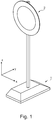
- Figure 1 shows a perspective view of a support 1 with a traffic sign 2, where the support 1 acts as a foot for the sign 2 concerned.
- the figure shows the three directions, a first direction X, a second direction Y and a third direction Z.
- Figure 2 shows a perspective view of a support 1 in one embodiment, where the support 1 comprises a first surface 3 and a second surface 4, and where the support 1 comprises two-parts, a first part 5 and a second part 6, where the first part 5 and the second part 6 are complementary to each other.
- the figures show that the first part 5 makes up most of the second surface 4 and the second part 6 makes up most of the first surface 3.
- Figure 2 further shows that the first part 5 and the second part 6 each further have carry- and handling means 7.
- the support 1 shows four apertures 8 configured for receipt of posts for e.g. road and traffic signs, where at least one aperture 8, extends from the first surface 3 towards the second surface 4 and where at least one aperture 8 is substantially perpendicular to the second surface 4 and that the at least one aperture 8 in the first part 5 extends through an aperture 8 in the second part 6 and thus the aperture 8 extends through the support 1.
- Figure 2 also shows that the support 1 comprises stackable means 9 and that the stackable means 9 are arranged at the first surface 3 as male portions 10.
- Figure 2 also shows that the support 1 further comprises a first side or first end 11 and a second side or second end 12, where the first side 11 is at least partly slanted from an outer position at the second surface 4 and in the direction towards an inner position of the first surface 3.
- Figure 2 also shows a support with a first side 11 and a second side 12, a third side 19 and a fourth side 20.
- the figure also shows the three directions, a first direction X, a second direction Y and a third direction Z.
- the figures 2-9 also show interlocking means as hook elements 22 along the assembly surface 18, where the free end 23 of the first part 5 is complementary to an intermediate part 24 of the second part 6 and where the free end 25 of the second part is complementary to an intermediate part 26 of the first part 5, where the free ends are thicker than the intermediate parts and where the hook elements 22 are configured for locking the support in the second direction Y.
- the interlocking means 13, in terms of the apertures 13a and the dowels 13b are configured for locking the support in the third direction Z.
- Figure 3 shows a perspective view of a support 1 during assembly where the first part 5 makes up most of the second surface 4 and the second part 6 makes up most of the first surface 3.
- Figure 4 shows a view from the first surface 3 of the first part 5 of a support 1 in one embodiment, where interlocking means 13 as well as apertures 13a are also shown.
- Figure 4 also shows a number of projections 17 which minimizes the risk of the first part 5 and the second part 6 sticking together at temperatures below 0 degree Celsius.
- a further function of the projections 17 is that they allow space for sand, small stones, etc. at the assembly surface 18 between the first part 5 and the second part 6 without influencing the interlocking means 13.
- the assembly surface 18 between the free end of the first part 5 is complementary to an intermediate part of the second part 6 and the free end of the second part 6 is complementary to an intermediate part of the first part 5.
- the assembly surface 18 is thus at various levels and with various steps, configured for locking the support in the second direction Y.
- the shown apertures 8 configured for receipt of posts for e.g. road and traffic signs, are coaxial with the apertures 8 in the second part 6.
- Figure 5 further shows the second surface 4 with stackable means 9 comprising female portions 14 complementary to the male portions 10 at the first surface 3 of the support 1.
- the figure also shows that the second surface 4 further comprises a number of male contact portions 15.
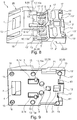
- Figure 6 shows a perspective view seen from the first surface 3 of the second part 6 of a support 1 in one embodiment
- figure 7 shows a perspective view seen from the second surface 4 of the second part 6 of a support 1 in one embodiment.
- Figures 6 and 7 also show interlocking means 13 as well as dowels 13b.
- the dowels 13b are intended for insertion at the apertures 13a shown e.g. at figure 4 , whereby the support 1 is then locked and secured in all the directions X, Y and Z, when the support 1 is moved in a straight line, being a linear movement.
- the support 1 is placed on a surface and the second part 6 of the support 1 is moved as part of a rotation around the X-axis, the support 1 is able to be opened and the first part 5 and the second part 6 are then able to be separated.
- Figure 8 and figure 9 shows a perspective view of the first part 5 of a support 1 in one embodiment as previously shown in figure 4 and figure 5 , respectively, where the first part 5 further comprises carry- and handling means 21.
- the carry- and handling means 21 are accessible from the third side 19 and the second surface 4 as well as from the fourth side 20 and the second surface 4.
Landscapes
- Engineering & Computer Science (AREA)
- Architecture (AREA)
- Civil Engineering (AREA)
- Structural Engineering (AREA)
- Road Signs Or Road Markings (AREA)
Priority Applications (1)
| Application Number | Priority Date | Filing Date | Title |
|---|---|---|---|
| PL17164155T PL3228751T3 (pl) | 2016-04-08 | 2017-03-31 | Wspornik np. dla znaku drogowego i drogowskazu |
Applications Claiming Priority (2)
| Application Number | Priority Date | Filing Date | Title |
|---|---|---|---|
| DKPA201600214 | 2016-04-08 | ||
| DKPA201670659 | 2016-08-29 |
Publications (2)
| Publication Number | Publication Date |
|---|---|
| EP3228751A1 EP3228751A1 (en) | 2017-10-11 |
| EP3228751B1 true EP3228751B1 (en) | 2019-09-25 |
Family
ID=58464380
Family Applications (1)
| Application Number | Title | Priority Date | Filing Date |
|---|---|---|---|
| EP17164155.8A Active EP3228751B1 (en) | 2016-04-08 | 2017-03-31 | Support for e.g. road and traffic signs |
Country Status (3)
| Country | Link |
|---|---|
| EP (1) | EP3228751B1 (pl) |
| DK (1) | DK3228751T3 (pl) |
| PL (1) | PL3228751T3 (pl) |
Families Citing this family (3)
| Publication number | Priority date | Publication date | Assignee | Title |
|---|---|---|---|---|
| CN111441642A (zh) * | 2020-03-16 | 2020-07-24 | 姚喜智 | 一种装配式多功能基座 |
| EP4650521A1 (en) | 2024-05-18 | 2025-11-19 | Marcin Buszko | Support for signs, temporary barriers and temporary fences |
| PL448604A1 (pl) * | 2024-05-18 | 2025-11-24 | Buszko Marcin Polmar Invest | Podpora pod znaki, barierki i ogrodzenia tymczasowe |
Family Cites Families (3)
| Publication number | Priority date | Publication date | Assignee | Title |
|---|---|---|---|---|
| US20070241255A1 (en) * | 2006-04-17 | 2007-10-18 | Joe Dvoracek | Traffic ballast system |
| AU2015201103A1 (en) * | 2007-02-08 | 2015-03-19 | Kelvindale Products Pty Ltd | Fence Anchor Block |
| US7631409B2 (en) * | 2007-03-28 | 2009-12-15 | Kelvindale Products Pty. Ltd. | Method of batch assembly of temporary fence panels and anchor blocks |
-
2017
- 2017-03-31 EP EP17164155.8A patent/EP3228751B1/en active Active
- 2017-03-31 PL PL17164155T patent/PL3228751T3/pl unknown
- 2017-03-31 DK DK17164155T patent/DK3228751T3/da active
Non-Patent Citations (1)
| Title |
|---|
| None * |
Also Published As
| Publication number | Publication date |
|---|---|
| PL3228751T3 (pl) | 2020-03-31 |
| EP3228751A1 (en) | 2017-10-11 |
| DK3228751T3 (da) | 2019-11-25 |
Similar Documents
| Publication | Publication Date | Title |
|---|---|---|
| EP3228751B1 (en) | Support for e.g. road and traffic signs | |
| AU2011274293B2 (en) | Temporary fence base | |
| AU2025201504B2 (en) | A weighted support assembly | |
| US6874242B2 (en) | Dual spacing width tile spacer | |
| US9556582B2 (en) | Hollow plastic deck block | |
| EP3655589B1 (en) | Rolling barrier system | |
| US5458434A (en) | Plastic barricade with handle and engagable stacking lug | |
| EP3585944B1 (en) | Crowd control and management barriers | |
| US6684580B1 (en) | Post stabilization support | |
| US20030145498A1 (en) | Portable sign support apparatus | |
| US10136530B2 (en) | Utility vault interlocking lid seat | |
| EP4692569A2 (en) | Nut connection mechanism | |
| AU2013100057B4 (en) | A Weighted Support Assembly | |
| US20210404128A1 (en) | Assembly for clamping formwork | |
| US10428475B2 (en) | Collapsible lane delineator | |
| US10760294B1 (en) | Safety apparatus | |
| GB2555807A (en) | Barrier | |
| AU2019280282B2 (en) | Modular walkway system | |
| US20170002529A1 (en) | Roadside barrier | |
| US20080010936A1 (en) | Edging Tiles | |
| US10179980B2 (en) | A-frame stand | |
| JP2008248477A (ja) | 仮設スロープ | |
| JP4652189B2 (ja) | 地被植物保護基板用表示板 | |
| JP3745983B2 (ja) | アンダーベース | |
| JP2005314989A (ja) | 敷板 |
Legal Events
| Date | Code | Title | Description |
|---|---|---|---|
| PUAI | Public reference made under article 153(3) epc to a published international application that has entered the european phase |
Free format text: ORIGINAL CODE: 0009012 |
|
| STAA | Information on the status of an ep patent application or granted ep patent |
Free format text: STATUS: THE APPLICATION HAS BEEN PUBLISHED |
|
| AK | Designated contracting states |
Kind code of ref document: A1 Designated state(s): AL AT BE BG CH CY CZ DE DK EE ES FI FR GB GR HR HU IE IS IT LI LT LU LV MC MK MT NL NO PL PT RO RS SE SI SK SM TR |
|
| AX | Request for extension of the european patent |
Extension state: BA ME |
|
| STAA | Information on the status of an ep patent application or granted ep patent |
Free format text: STATUS: REQUEST FOR EXAMINATION WAS MADE |
|
| 17P | Request for examination filed |
Effective date: 20180409 |
|
| RBV | Designated contracting states (corrected) |
Designated state(s): AL AT BE BG CH CY CZ DE DK EE ES FI FR GB GR HR HU IE IS IT LI LT LU LV MC MK MT NL NO PL PT RO RS SE SI SK SM TR |
|
| R17P | Request for examination filed (corrected) |
Effective date: 20180409 |
|
| STAA | Information on the status of an ep patent application or granted ep patent |
Free format text: STATUS: EXAMINATION IS IN PROGRESS |
|
| 17Q | First examination report despatched |
Effective date: 20181212 |
|
| GRAP | Despatch of communication of intention to grant a patent |
Free format text: ORIGINAL CODE: EPIDOSNIGR1 |
|
| STAA | Information on the status of an ep patent application or granted ep patent |
Free format text: STATUS: GRANT OF PATENT IS INTENDED |
|
| INTG | Intention to grant announced |
Effective date: 20190522 |
|
| GRAS | Grant fee paid |
Free format text: ORIGINAL CODE: EPIDOSNIGR3 |
|
| GRAA | (expected) grant |
Free format text: ORIGINAL CODE: 0009210 |
|
| STAA | Information on the status of an ep patent application or granted ep patent |
Free format text: STATUS: THE PATENT HAS BEEN GRANTED |
|
| AK | Designated contracting states |
Kind code of ref document: B1 Designated state(s): AL AT BE BG CH CY CZ DE DK EE ES FI FR GB GR HR HU IE IS IT LI LT LU LV MC MK MT NL NO PL PT RO RS SE SI SK SM TR |
|
| REG | Reference to a national code |
Ref country code: GB Ref legal event code: FG4D |
|
| REG | Reference to a national code |
Ref country code: CH Ref legal event code: EP |
|
| REG | Reference to a national code |
Ref country code: AT Ref legal event code: REF Ref document number: 1183945 Country of ref document: AT Kind code of ref document: T Effective date: 20191015 |
|
| REG | Reference to a national code |
Ref country code: IE Ref legal event code: FG4D |
|
| REG | Reference to a national code |
Ref country code: DE Ref legal event code: R096 Ref document number: 602017007236 Country of ref document: DE |
|
| REG | Reference to a national code |
Ref country code: DK Ref legal event code: T3 Effective date: 20191122 |
|
| RAP2 | Party data changed (patent owner data changed or rights of a patent transferred) |
Owner name: CJ INNOVATION APS |
|
| REG | Reference to a national code |
Ref country code: NO Ref legal event code: T2 Effective date: 20190925 |
|
| REG | Reference to a national code |
Ref country code: SE Ref legal event code: TRGR |
|
| REG | Reference to a national code |
Ref country code: NL Ref legal event code: MP Effective date: 20190925 |
|
| PG25 | Lapsed in a contracting state [announced via postgrant information from national office to epo] |
Ref country code: FI Free format text: LAPSE BECAUSE OF FAILURE TO SUBMIT A TRANSLATION OF THE DESCRIPTION OR TO PAY THE FEE WITHIN THE PRESCRIBED TIME-LIMIT Effective date: 20190925 Ref country code: LT Free format text: LAPSE BECAUSE OF FAILURE TO SUBMIT A TRANSLATION OF THE DESCRIPTION OR TO PAY THE FEE WITHIN THE PRESCRIBED TIME-LIMIT Effective date: 20190925 Ref country code: HR Free format text: LAPSE BECAUSE OF FAILURE TO SUBMIT A TRANSLATION OF THE DESCRIPTION OR TO PAY THE FEE WITHIN THE PRESCRIBED TIME-LIMIT Effective date: 20190925 Ref country code: BG Free format text: LAPSE BECAUSE OF FAILURE TO SUBMIT A TRANSLATION OF THE DESCRIPTION OR TO PAY THE FEE WITHIN THE PRESCRIBED TIME-LIMIT Effective date: 20191225 |
|
| REG | Reference to a national code |
Ref country code: LT Ref legal event code: MG4D |
|
| PG25 | Lapsed in a contracting state [announced via postgrant information from national office to epo] |
Ref country code: LV Free format text: LAPSE BECAUSE OF FAILURE TO SUBMIT A TRANSLATION OF THE DESCRIPTION OR TO PAY THE FEE WITHIN THE PRESCRIBED TIME-LIMIT Effective date: 20190925 Ref country code: RS Free format text: LAPSE BECAUSE OF FAILURE TO SUBMIT A TRANSLATION OF THE DESCRIPTION OR TO PAY THE FEE WITHIN THE PRESCRIBED TIME-LIMIT Effective date: 20190925 Ref country code: GR Free format text: LAPSE BECAUSE OF FAILURE TO SUBMIT A TRANSLATION OF THE DESCRIPTION OR TO PAY THE FEE WITHIN THE PRESCRIBED TIME-LIMIT Effective date: 20191226 |
|
| REG | Reference to a national code |
Ref country code: AT Ref legal event code: MK05 Ref document number: 1183945 Country of ref document: AT Kind code of ref document: T Effective date: 20190925 |
|
| PG25 | Lapsed in a contracting state [announced via postgrant information from national office to epo] |
Ref country code: RO Free format text: LAPSE BECAUSE OF FAILURE TO SUBMIT A TRANSLATION OF THE DESCRIPTION OR TO PAY THE FEE WITHIN THE PRESCRIBED TIME-LIMIT Effective date: 20190925 Ref country code: ES Free format text: LAPSE BECAUSE OF FAILURE TO SUBMIT A TRANSLATION OF THE DESCRIPTION OR TO PAY THE FEE WITHIN THE PRESCRIBED TIME-LIMIT Effective date: 20190925 Ref country code: PT Free format text: LAPSE BECAUSE OF FAILURE TO SUBMIT A TRANSLATION OF THE DESCRIPTION OR TO PAY THE FEE WITHIN THE PRESCRIBED TIME-LIMIT Effective date: 20200127 Ref country code: AT Free format text: LAPSE BECAUSE OF FAILURE TO SUBMIT A TRANSLATION OF THE DESCRIPTION OR TO PAY THE FEE WITHIN THE PRESCRIBED TIME-LIMIT Effective date: 20190925 Ref country code: NL Free format text: LAPSE BECAUSE OF FAILURE TO SUBMIT A TRANSLATION OF THE DESCRIPTION OR TO PAY THE FEE WITHIN THE PRESCRIBED TIME-LIMIT Effective date: 20190925 Ref country code: AL Free format text: LAPSE BECAUSE OF FAILURE TO SUBMIT A TRANSLATION OF THE DESCRIPTION OR TO PAY THE FEE WITHIN THE PRESCRIBED TIME-LIMIT Effective date: 20190925 Ref country code: EE Free format text: LAPSE BECAUSE OF FAILURE TO SUBMIT A TRANSLATION OF THE DESCRIPTION OR TO PAY THE FEE WITHIN THE PRESCRIBED TIME-LIMIT Effective date: 20190925 Ref country code: IT Free format text: LAPSE BECAUSE OF FAILURE TO SUBMIT A TRANSLATION OF THE DESCRIPTION OR TO PAY THE FEE WITHIN THE PRESCRIBED TIME-LIMIT Effective date: 20190925 |
|
| PG25 | Lapsed in a contracting state [announced via postgrant information from national office to epo] |
Ref country code: IS Free format text: LAPSE BECAUSE OF FAILURE TO SUBMIT A TRANSLATION OF THE DESCRIPTION OR TO PAY THE FEE WITHIN THE PRESCRIBED TIME-LIMIT Effective date: 20200224 Ref country code: CZ Free format text: LAPSE BECAUSE OF FAILURE TO SUBMIT A TRANSLATION OF THE DESCRIPTION OR TO PAY THE FEE WITHIN THE PRESCRIBED TIME-LIMIT Effective date: 20190925 Ref country code: SM Free format text: LAPSE BECAUSE OF FAILURE TO SUBMIT A TRANSLATION OF THE DESCRIPTION OR TO PAY THE FEE WITHIN THE PRESCRIBED TIME-LIMIT Effective date: 20190925 Ref country code: SK Free format text: LAPSE BECAUSE OF FAILURE TO SUBMIT A TRANSLATION OF THE DESCRIPTION OR TO PAY THE FEE WITHIN THE PRESCRIBED TIME-LIMIT Effective date: 20190925 |
|
| REG | Reference to a national code |
Ref country code: DE Ref legal event code: R097 Ref document number: 602017007236 Country of ref document: DE |
|
| PG2D | Information on lapse in contracting state deleted |
Ref country code: IS |
|
| PG25 | Lapsed in a contracting state [announced via postgrant information from national office to epo] |
Ref country code: IS Free format text: LAPSE BECAUSE OF FAILURE TO SUBMIT A TRANSLATION OF THE DESCRIPTION OR TO PAY THE FEE WITHIN THE PRESCRIBED TIME-LIMIT Effective date: 20200126 |
|
| PLBE | No opposition filed within time limit |
Free format text: ORIGINAL CODE: 0009261 |
|
| STAA | Information on the status of an ep patent application or granted ep patent |
Free format text: STATUS: NO OPPOSITION FILED WITHIN TIME LIMIT |
|
| 26N | No opposition filed |
Effective date: 20200626 |
|
| PG25 | Lapsed in a contracting state [announced via postgrant information from national office to epo] |
Ref country code: MC Free format text: LAPSE BECAUSE OF FAILURE TO SUBMIT A TRANSLATION OF THE DESCRIPTION OR TO PAY THE FEE WITHIN THE PRESCRIBED TIME-LIMIT Effective date: 20190925 |
|
| REG | Reference to a national code |
Ref country code: CH Ref legal event code: PL |
|
| PG25 | Lapsed in a contracting state [announced via postgrant information from national office to epo] |
Ref country code: SI Free format text: LAPSE BECAUSE OF FAILURE TO SUBMIT A TRANSLATION OF THE DESCRIPTION OR TO PAY THE FEE WITHIN THE PRESCRIBED TIME-LIMIT Effective date: 20190925 |
|
| REG | Reference to a national code |
Ref country code: BE Ref legal event code: MM Effective date: 20200331 |
|
| PG25 | Lapsed in a contracting state [announced via postgrant information from national office to epo] |
Ref country code: LU Free format text: LAPSE BECAUSE OF NON-PAYMENT OF DUE FEES Effective date: 20200331 |
|
| PG25 | Lapsed in a contracting state [announced via postgrant information from national office to epo] |
Ref country code: CH Free format text: LAPSE BECAUSE OF NON-PAYMENT OF DUE FEES Effective date: 20200331 Ref country code: IE Free format text: LAPSE BECAUSE OF NON-PAYMENT OF DUE FEES Effective date: 20200331 Ref country code: LI Free format text: LAPSE BECAUSE OF NON-PAYMENT OF DUE FEES Effective date: 20200331 Ref country code: FR Free format text: LAPSE BECAUSE OF NON-PAYMENT OF DUE FEES Effective date: 20200331 |
|
| PG25 | Lapsed in a contracting state [announced via postgrant information from national office to epo] |
Ref country code: BE Free format text: LAPSE BECAUSE OF NON-PAYMENT OF DUE FEES Effective date: 20200331 |
|
| GBPC | Gb: european patent ceased through non-payment of renewal fee |
Effective date: 20210331 |
|
| PG25 | Lapsed in a contracting state [announced via postgrant information from national office to epo] |
Ref country code: GB Free format text: LAPSE BECAUSE OF NON-PAYMENT OF DUE FEES Effective date: 20210331 |
|
| PG25 | Lapsed in a contracting state [announced via postgrant information from national office to epo] |
Ref country code: TR Free format text: LAPSE BECAUSE OF FAILURE TO SUBMIT A TRANSLATION OF THE DESCRIPTION OR TO PAY THE FEE WITHIN THE PRESCRIBED TIME-LIMIT Effective date: 20190925 Ref country code: MT Free format text: LAPSE BECAUSE OF FAILURE TO SUBMIT A TRANSLATION OF THE DESCRIPTION OR TO PAY THE FEE WITHIN THE PRESCRIBED TIME-LIMIT Effective date: 20190925 Ref country code: CY Free format text: LAPSE BECAUSE OF FAILURE TO SUBMIT A TRANSLATION OF THE DESCRIPTION OR TO PAY THE FEE WITHIN THE PRESCRIBED TIME-LIMIT Effective date: 20190925 |
|
| PG25 | Lapsed in a contracting state [announced via postgrant information from national office to epo] |
Ref country code: MK Free format text: LAPSE BECAUSE OF FAILURE TO SUBMIT A TRANSLATION OF THE DESCRIPTION OR TO PAY THE FEE WITHIN THE PRESCRIBED TIME-LIMIT Effective date: 20190925 |
|
| PGFP | Annual fee paid to national office [announced via postgrant information from national office to epo] |
Ref country code: SE Payment date: 20250312 Year of fee payment: 9 |
|
| PGFP | Annual fee paid to national office [announced via postgrant information from national office to epo] |
Ref country code: DE Payment date: 20250327 Year of fee payment: 9 |
|
| PGFP | Annual fee paid to national office [announced via postgrant information from national office to epo] |
Ref country code: DK Payment date: 20250325 Year of fee payment: 9 |
|
| PGFP | Annual fee paid to national office [announced via postgrant information from national office to epo] |
Ref country code: NO Payment date: 20250327 Year of fee payment: 9 |
|
| PGFP | Annual fee paid to national office [announced via postgrant information from national office to epo] |
Ref country code: PL Payment date: 20250305 Year of fee payment: 9 |