EP3228528A1 - Seat attachment structure of saddle riding vehicle - Google Patents
Seat attachment structure of saddle riding vehicle Download PDFInfo
- Publication number
- EP3228528A1 EP3228528A1 EP17160776.5A EP17160776A EP3228528A1 EP 3228528 A1 EP3228528 A1 EP 3228528A1 EP 17160776 A EP17160776 A EP 17160776A EP 3228528 A1 EP3228528 A1 EP 3228528A1
- Authority
- EP
- European Patent Office
- Prior art keywords
- seat
- vehicle body
- seat attachment
- section
- attachment member
- Prior art date
- Legal status (The legal status is an assumption and is not a legal conclusion. Google has not performed a legal analysis and makes no representation as to the accuracy of the status listed.)
- Granted
Links
Images






Classifications
-
- B—PERFORMING OPERATIONS; TRANSPORTING
- B62—LAND VEHICLES FOR TRAVELLING OTHERWISE THAN ON RAILS
- B62J—CYCLE SADDLES OR SEATS; AUXILIARY DEVICES OR ACCESSORIES SPECIALLY ADAPTED TO CYCLES AND NOT OTHERWISE PROVIDED FOR, e.g. ARTICLE CARRIERS OR CYCLE PROTECTORS
- B62J1/00—Saddles or other seats for cycles; Arrangement thereof; Component parts
- B62J1/12—Box-shaped seats; Bench-type seats, e.g. dual or twin seats
-
- B—PERFORMING OPERATIONS; TRANSPORTING
- B62—LAND VEHICLES FOR TRAVELLING OTHERWISE THAN ON RAILS
- B62J—CYCLE SADDLES OR SEATS; AUXILIARY DEVICES OR ACCESSORIES SPECIALLY ADAPTED TO CYCLES AND NOT OTHERWISE PROVIDED FOR, e.g. ARTICLE CARRIERS OR CYCLE PROTECTORS
- B62J1/00—Saddles or other seats for cycles; Arrangement thereof; Component parts
- B62J1/08—Frames for saddles; Connections between saddle frames and seat pillars; Seat pillars
-
- B—PERFORMING OPERATIONS; TRANSPORTING
- B62—LAND VEHICLES FOR TRAVELLING OTHERWISE THAN ON RAILS
- B62J—CYCLE SADDLES OR SEATS; AUXILIARY DEVICES OR ACCESSORIES SPECIALLY ADAPTED TO CYCLES AND NOT OTHERWISE PROVIDED FOR, e.g. ARTICLE CARRIERS OR CYCLE PROTECTORS
- B62J1/00—Saddles or other seats for cycles; Arrangement thereof; Component parts
- B62J1/02—Saddles resiliently mounted on the frame; Equipment therefor, e.g. springs
-
- B—PERFORMING OPERATIONS; TRANSPORTING
- B62—LAND VEHICLES FOR TRAVELLING OTHERWISE THAN ON RAILS
- B62J—CYCLE SADDLES OR SEATS; AUXILIARY DEVICES OR ACCESSORIES SPECIALLY ADAPTED TO CYCLES AND NOT OTHERWISE PROVIDED FOR, e.g. ARTICLE CARRIERS OR CYCLE PROTECTORS
- B62J1/00—Saddles or other seats for cycles; Arrangement thereof; Component parts
- B62J1/02—Saddles resiliently mounted on the frame; Equipment therefor, e.g. springs
- B62J1/04—Saddles capable of swinging about a horizontal pivot
-
- B—PERFORMING OPERATIONS; TRANSPORTING
- B62—LAND VEHICLES FOR TRAVELLING OTHERWISE THAN ON RAILS
- B62K—CYCLES; CYCLE FRAMES; CYCLE STEERING DEVICES; RIDER-OPERATED TERMINAL CONTROLS SPECIALLY ADAPTED FOR CYCLES; CYCLE AXLE SUSPENSIONS; CYCLE SIDECARS, FORECARS, OR THE LIKE
- B62K2201/00—Springs used in cycle frames or parts thereof
- B62K2201/02—Rubber springs
Definitions
- the present invention relates to a seat attachment structure of a saddle riding vehicle such as a motorcycle or the like.
- a hook formed at a front section of a front seat is locked to a locking tool installed at a main frame of the vehicle body, and an arm section protruding from a rear section of the front seat is fitted into a protrusion protruding from a cross member of the vehicle body. Then, a rear seat locked while assembled to the vehicle body is disposed at the rear section of the front seat, and a pressing section protruding from the front section of the rear seat is formed to restrict upward displacement of the arm section of the rear section of the front seat.
- An aspect of the present invention is directed to provide a seat attachment structure of a saddle riding vehicle capable of increasing attachment workability of a seat.
- a seat attachment structure of a saddle riding vehicle according to the present invention employs the following configurations in order to solve the above-mentioned problems.
- the seat attachment member is swingably attached to the vehicle body by the vehicle body-side connecting section.
- the other end side (second end side) of the vehicle body in the forward/rearward direction is attached to the seat fixing section of the seat attachment member.
- the seat attachment member since the seat attachment member is swingable with respect to the vehicle body via the vehicle body-side connecting section, the seat attachment member can adjust an inclination attitude or position with respect to the vehicle body when the other end side (second end side) of the seat in the forward/rearward direction of the vehicle body is attached to the seat fixing section. For this reason, even when a machining error or a formation error occurs in each portion of the component, the seat can be easily attached to the vehicle body.
- the swing range of the seat attachment member is restricted by the swing restriction section within an appropriate range, and excessive positional deviation of the seat attachment member can be suppressed.
- a reaction according to a swing amount of the seat attachment member can be obtained by the first elastic member, and when attachment work of the seat is terminated, the seat attachment member can be returned to an appropriate position.
- the seat attachment member abuts the swing restriction section of the vehicle body side via the first elastic member, occurrence of abutting noise when the seat attachment member is abruptly swung can be suppressed by the first elastic member.
- reaction properties of the second elastic member can be easily set and varied.
- reaction properties of the second elastic members of the plurality of vehicle body-side connecting sections formed on the same straight line in the vehicle width direction can be uniformly and accurately set.
- the seat attachment member having the vehicle body-side connecting section swingably attached to the vehicle body and the seat fixing section to which the other end side of the seat is attached is provided, in a state in which one end side of the seat in the forward/rearward direction is locked to the vehicle body, the other end side of the seat in the forward/rearward direction is attached to the seat fixing section of the seat attachment member while the inclination attitude or position of the seat attachment member is finely adjusted. Accordingly, according to the aspect of the present invention, attachment workability of the seat can be improved.
- an arrow FR showing a forward direction with respect to a vehicle
- an arrow LH showing a leftward direction with respect to the vehicle
- an arrow UP showing an upward direction with respect to the vehicle
- FIG. 1 is a view showing a left side-surface of a saddle riding vehicle according to the embodiment.
- the saddle riding vehicle according to the embodiment is a so-called cruiser type motorcycle 1 in which a vehicle height is decreased and a forward/rearward length is increased.
- a front wheel Wf of the motorcycle 1 is rotatably supported by lower end portions of a pair of left and right front forks 3.
- the left and right front forks 3 are supported by a head pipe 2 of a front end portion of a vehicle body frame F via upper and lower bridge members 5 and a steering stem (not shown).
- a bar type steering handle 6 is attached to the upper bridge member 5.
- a rear wheel Wr of the motorcycle 1 is supported by rear end portions of a swing arm 8.
- a front end portion of the swing arm 8 is vertically swingably supported by a pivot section 13a of the vehicle body frame F.
- the rear wheel Wr is linked to an engine 30 serving as a motor of the motorcycle 1 via, for example, a power train or the like constituted by a chain 7.
- Lower end portions of rear cushions 9 serving as a suspension component of the rear wheel Wr side are connected to the swing arm 8 in the vicinity of a rear wheel support section.
- FIGS. 2 and 3 are views showing a major part of the vehicle body frame F of the motorcycle 1.
- the vehicle body frame F includes the head pipe 2 disposed at a front end portion of the vehicle body frame F and configured to support a steering stem (not shown), a pair of left and right main frames 14 branched off from an upper rear side of the head pipe 2 toward left and right sides, extending rearward and downward when seen in a side view and then changing directions at rear curved sections 14a to extend downward, a pair of left and right down frames 15 branched off from a lower rear side of the head pipe 2 toward left and right sides and extending rearward and downward to be steeply inclined more than the main frames 14 when seen in a side view, a rear frame 16 connected to rear upper surface sides of the left and right main frames 14, and a rear fender frame 60 having a front region connected to the rear frame 16 and configured to support a rear fender 50 that covers the rear wheel Wr from above. Further, in FIG. 2 , the rear fender frame 60 is not shown.
- Both of the left and right main frames 14 and the down frames 15 are formed by bending round steel tubes.
- the left and right main frames 14 are curved toward the outside in the vehicle width direction from joining sections at front end portions joining with the head pipe 2 such that once a separation width therebetween is a constant width once, the separation width therebetween is narrowed toward the vicinity of the rear curved sections 14a, and then the separation width is widened again downward from the vicinity of the rear curved sections 14a.
- the left and right main frames 14 are connected by a plurality of cross pipes 18A, 18B and 18C.
- a front section of a fuel tank 19 is disposed over front section sides of the left and right main frames 14, and a rear section of the fuel tank 19 and an occupant-seating seat 20 are disposed over a region in which the separation width is small of rear section sides of the left and right main frames 14 via the rear frame 16.
- a pivot plate 17 is attached to the rear curved sections 14a of the left and right main frames 14 and lower regions thereof.
- the pivot section 13a configured to support a front end portion of the swing arm 8 is attached to the pivot plate 17.
- the left and right down frames 15 are connected to each other by a plurality of cross pipes 21A and 21B, and upper regions of the left and right down frames 15 are connected to front regions of the left and right main frames 14 by cassette frames 22A and 22B.
- a power unit PU in which the engine 30 and a gear box 31 are integrated is disposed at a region surrounded by the down frames 15 and the main frames 14.
- the power unit PU is attached to the down frames 15 and the main frames 14 and constitutes a portion of the vehicle body frame F.
- the rear frame 16 has a pair of left and right seat frame sections 23L and 23R extending from upper surfaces of the left and right main frames 14 in the vicinity of the rear curved sections 14a toward rear upper sides (extending toward rear positions of a seat 20), and a connecting section 23A curved in substantially a U shape and configured to connect rear sections of the left and right seat frame sections 23L and 23R.
- the left and right seat frame sections 23L and 23R and the connecting section 23A are integrally formed by bending a round steel tube.
- the left and right seat frame sections 23L and 23R or the connecting section 23A may be constituted by a separate member.
- the rear frame 16 further has a pair of left and right seat sub-frame sections 24L and 24R extending from substantially intermediate positions in the extension direction of the left and right seat frame sections 23L and 23R toward front upper sides and having front end portions connected to the left and right main frames 14.
- left and right seat sub-frame sections 24L and 24R are formed in a substantially linear shape when seen in a side view, the left and right seat sub-frame sections 24L and 24R are bent inward in the vehicle width direction such that central regions in the extension direction approach each other when seen in a plan view. Portions close to sections of the left and right seat sub-frame sections 24L and 24R that are closest to each other are connected to each other by a cross pipe 25.
- the rear regions of the seat sub-frame sections 24L and 24R and the seat frame sections 23L and 23R are reinforced by cassette frames 26 extending substantially horizontally.
- the left and right seat frame sections 23L and 23R are connected to each other by a cross pipe 27 at positions closer to an area above the rear sections than the connecting sections to the left and right seat sub-frame sections 24L and 24R.
- the rear fender frame 60 includes a pair of side frame sections 60L and 60R disposed at both of left and right sides in the vehicle width direction, and a center plate (not shown) curved to connect the rear region of the pair of side frame sections 60L and 60R at an upper side thereof.
- the left and right side frame sections 60L and 60R have arc regions 60a having arc shapes substantially along an upper section shape of the rear wheel Wr, and front regions 60b extending forward from front sections of the arc regions 60a, when seen in a side view.
- the front regions 60b of the left and right side frame sections 60L and 60R are disposed inside in the vehicle width direction of the left and right seat frame sections 23L and 23R and fastened and fixed to the corresponding left and right seat frame sections 23L and 23R at a plurality of places.
- the rear fender 50 is attached to an upper surface side of the center plate (not shown).
- FIG. 4 is a view showing the vicinity of the connecting section of the rear frame 16 and the rear fender frame 60 from above the left front section of the vehicle body.
- FIG. 5 is a view showing a front side region of the left side frame section 60L of the rear fender frame 60 from above the left front section of the vehicle body.
- Swelling regions 60c swelling upward with respect to the front edge portions of the arc regions 60a and the front regions 60b are formed between the front regions 60b and the arc regions 60a of the left and right side frame sections 60L and 60R.
- a seat attachment member 60S a major part of which is formed of a metal such as an aluminum alloy or the like, bridges the swelling regions 60c of the left and right side frame sections 60L and 60R.
- FIG. 6 is a view showing the seat attachment member 60S when seen from above the vehicle
- FIG. 7 is a side view of the motorcycle 1 in which the seat attachment member 60S and the vicinity of the attachment section thereof are enlarged.
- the seat attachment member 60S has a main body section 60S-1 formed in substantially a shallow box shape, a lower side of which is open, front protrusion sections 60S-2 fixed to regions of the main body section 60S-1 close to front end portions of left and right sidewalls through welding, and rear protrusion sections 60S-3 fixed to regions of the main body section 60S-1 close to rear end portions of the left and right sidewalls.
- a regulator (regulator/rectifier) (not shown) is fastened and fixed to a lower surface side of an upper flat wall 60S-1u of the main body section 60S-1 by a bolt 66.
- the regulator converts alternating current power generated by a generator into direct current at a voltage of a specified voltage or less.
- a pair of fastening holes 40 configured to fasten and fix a lower surface of a rear section side of the seat 20 are formed in a rear wall 60S-1r of the main body section 60S-1.
- the pair of fastening holes 40 are formed at positions separated in the vehicle width direction of the rear wall 60S-1r.
- Weld nuts 39 are attached to back surface sides of the fastening holes 40 of the rear wall 60S-1r.
- the fastening holes 40 of the rear wall 60S-1r and the weld nuts 39 constitute a seat fixing section to which the rear section of the occupant-seating seat 20 is fixed.
- the seat fixing section constituted by the fastening holes 40 and the weld nuts 39 may be formed on another portion, for example, the upper wall 60S-1u, as long as they are disposed at positions separated from the front protrusion section 60S-2 in the forward/rearward direction of the vehicle body without being limited to the rear wall 60S-1r of the main body section 60S-1.
- the left and right front protrusion sections 60S-2 of the seat attachment member 60S have substantially horizontal upper walls 60S-2u, and hanging walls 60S-2f extending to be bent downward from front end portions of the upper walls 60S-2u. Insertion holes (not shown) are formed in the upper walls 60S-2u of the front protrusion sections 60S-2, and bolts 41 configured to fix the front protrusion sections 60S-2 to the corresponding left and right side frame sections 60L and 60R are inserted through the insertion holes. Rubber bushes 42u and 421 serving as second elastic members are disposed to overlap upper surface sides and lower surface sides of the upper walls 60S-2u of the front protrusion sections 60S-2.
- washers 43 overlap an upper surface of the rubber bush 42u of an upper side and a lower surface of the rubber bush 421 of a lower side, and the upper and lower rubber bushes 42u and 421 are fixed to the corresponding left and right side frame sections 60L and 60R by the bolts 41 while the upper walls 60S-2u of the front protrusion sections 60S-2 are sandwiched therebetween.
- portions of the upper walls 60S-2u of the left and right front protrusion sections 60S-2 are swingably attached to the corresponding left and right side frame sections 60L and 60R via the rubber bushes 42u and 421.
- shaft center sections of the upper and lower rubber bushes 42u and 421 are fixed to the corresponding side frame sections 60L and 60R by the bolts 41, and outer circumferential edge portions of the upper and lower rubber bushes 42u and 421 are pressure-welded to upper and lower surfaces of the upper walls 60S-2u of the front protrusion sections 60S-2and the washers 43.
- the seat attachment member 60S receive initial loads of the upper and lower rubber bushes 42u and 421 to be maintained at a constant position and a constant attitude, and when an external force is applied in this state, fine displacement is allowed due to elastic deformation of the rubber bushes 42u and 421.
- the left and right front protrusion sections 60S-2 of the seat attachment member 60S are formed at left and right symmetrical positions of the main body section 60S-1. Accordingly, portions of the upper walls 60S-2u of the left and right front protrusion sections 60S-2 are attached to the vehicle body (the side frame sections 60L and 60R) together with the upper and lower rubber bushes 42u and 421 in a state so as to be swingable in a gravity direction using an axis O in the vehicle width direction as a swing axis.
- the upper walls 60S-2u of the left and right front protrusion sections 60S-2 and the upper and lower rubber bushes 42u and 421 constitute a vehicle body-side connecting section in the seat attachment member 60S.
- the seat attachment member 60S is inclined upward toward a rear side of the vehicle body such that the upper walls 60S-1u of the main body section 60S-1 are disposed substantially along inclinations of the side frame sections 60L and 60R in a state in which the left and right front protrusion sections 60S-2 are attached to the left and right side frame sections 60L and 60R via the rubber bushes 42u and 421 as shown in FIG. 7 .
- the left and right rear protrusion sections 60S-3 of the seat attachment member 60S have restriction walls 60S-3a inclined upward toward a rear side of the vehicle body substantially along the upper walls 60S-1u of the main body section 60S-1.
- Rubber shock-absorbing members 44 (first elastic members) are attached to the restriction walls 60S-3a.
- the rubber shock-absorbing members 44 have substantially columnar load receiving sections protruding downward the restriction walls 60S-3a.
- rubber shock-absorbing members 45 (second elastic members) are also attached to the hanging walls 60S-2f of the left and right front protrusion sections 60S-2 of the seat attachment member 60S.
- the rubber shock-absorbing members 45 have substantially spherical load receiving sections protruding toward rear sides of the hanging walls 60S-2f.
- the swelling regions 60c of the side frame sections 60L and 60R have projections 60c-1 with front surfaces 60c-1f standing in the vertical direction and upper surfaces 60c-1u extending substantially horizontally from upper ends of the front surfaces 60c-1f toward a rear side of the vehicle body, and the seat attachment member 60S is attached to the upper surfaces 60c-lu of the projections 60c-1.
- fastening holes 46 are formed in the upper surfaces 60c-1u of the projections 60c-1, and tip portions of the bolts 41 passing through the front protrusion sections 60S-2 of the seat attachment member 60S and the rubber bushes 42u and 421 are fastened and fixed to the fastening holes 46.
- the seat attachment member 60S is attached to the front protrusion sections 60S-2 of the seat attachment member 60S in a state in which the washer 43 disposed at a lower surface side of the rubber bush 421 abuts the upper surface 60c-1u of the projection 60c-1.
- the rubber shock-absorbing members 45 attached to the hanging walls 60S-2f of the front protrusion sections 60S-2 of the seat attachment member 60S abut the front surfaces 60c-1f of the projections 60c-1.
- the hanging walls 60S-2f restrict excessive pivotal movement of the seat attachment member 60S in one direction about the portions of the rubber bushes 42u and 421 as a center (a pivot support point) by causing the hanging walls 60S-2f to abut the front surfaces 60c-1f of the projections 60c-1 via the rubber shock-absorbing members 45.
- the front surfaces 60c-1f of the projections 60c-1 constitute a swing restriction section (a first swing restriction section, a receiving surface) configured to restrict a swing range of the seat attachment member 60S.
- the swelling regions 60c of the side frame sections 60L and 60R include recessed sections 47 adjacent to rear sides of the projections 60c-1, and substantially triangular raised sections 60c-2 adjacent to rear sides of the recessed sections 47 when seen in a side view.
- Extension walls 48 extending toward an upper side of the rear section protrude from the raised sections 60c-2.
- Upper surfaces 48u of the extension walls 48 are flatly formed, and the rubber shock-absorbing members 44 attached to the rear protrusion sections 60S-3 of the seat attachment member 60S abut the upper surfaces 48u.
- the restriction wall 60S-3a restricts excessive pivotal movement in the other direction about portions of the rubber bushes 42u and 421 of the seat attachment member 60S (using a pivot support point) by causing the restriction wall 60S-3a to abut the upper surfaces 48u of the extension walls 48 via the rubber shock-absorbing members 44.
- the upper surfaces 48u of the restriction walls 60S-3a constitute a swing restriction section (a second swing restriction section, a receiving surface) configured to restrict a swing range of the seat attachment member 60S.
- the rubber shock-absorbing members 44 are attached to the restriction walls 60S-3a of the rear protrusion sections 60S-3 in the embodiment, the rubber shock-absorbing members 44 may be attached to the vehicle body side (for example, the upper surfaces 48u of the extension walls 48).
- the rubber shock-absorbing members 45 are attached to the hanging walls 60S-2f of the front protrusion sections 60S-2 in the embodiment, the rubber shock-absorbing members 45 may be attached to the vehicle body side (for example, the front surfaces 60c-1f of the projections 60c-1 of the side frame sections 60L and 60R).
- FIG. 8 is a view showing a longitudinal cross section in which a bottom section of the occupant-seating seat 20 is cut substantially along the forward/rearward direction of the vehicle body.
- a seat frame or a cushion material (not shown) is supported by a bottom plate 49.
- An engaging hook 51 protruding toward a front side of the vehicle body in substantially an L shape extends from a lower surface of a front section side of the bottom plate 49. As shown in FIG. 4 , the engaging hook 51 is inserted into a lower side of a locking plate 52 that bridges the left and right seat sub-frame sections 24L and 24R from a rear side of the vehicle body to be locked by the locking plate 52.
- an attachment flange 49f continuously extends from the rear section of the bottom plate 49, and a pair of fastening bolts 54 are held at the attachment flange 49f via rubber bushes 53. Shaft sections of the fastening bolts 54 are locked into the fastening holes 40 of the rear walls 60S-1r of the seat attachment member 60S and the weld nuts 39 of the back portion.
- the upper and lower rubber bushes 42u and 421 configured to swingably support the front protrusion sections 60S-2 of the seat attachment member 60S at the side frame sections 60L and 60R are formed in the shape as shown in FIG. 9 .
- the upper and lower rubber bushes 42u and 421 have the same shape, shaft holes 28 into which the shaft sections of the bolts 41 are fitted are formed in the shaft center sections, and a plurality of cutout grooves 29 (notches) are radially formed at one end surface in the axial direction abutting the washers 43.
- the rubber bushes 42u and 421 attached to the left and right front protrusion sections 60S-2 of the seat attachment member 60S employ the same specifications including shapes (shapes and the number) of the cutout grooves 29.
- the engaging hook 51 at the front section side (one end side of the seat 20, first end side of the seat 20) of the bottom plate 49 of the seat 20 is locked to the locking plate 52 of the vehicle body side, and in this state, the rear section side (another end side of the seat 20, second end side of the seat 20) of the bottom plate 49 is fastened and fixed to the rear section of the main body section 60S-1 of the seat attachment member 60S by the fastening bolts 54.
- the shaft sections of the fastening bolts 54 are inserted into the fastening holes 40 corresponding to the rear section of the seat attachment member 60S, the shaft sections of the fastening bolts 54 are inserted into the corresponding fastening holes 40 by appropriately swinging the seat attachment member 60S at the portions of the left and right front protrusion sections 60S-2 while using the rubber bushes 42u and 421.
- the rear section of the seat 20 is fastened and fixed to the vehicle body side via the seat attachment member 60S by fastening the fastening bolts 54.
- the seat attachment structure includes the seat attachment member 60S including the front protrusion sections 60S-2 that are swingably attached to the side frame sections 60L and 60R of the rear fender frame 60 at the front side of the seat attachment member 60S, and the seat fixing section (the fastening holes 40 and the weld nuts 39) to which the rear end portion of the seat 20 is attached at the rear side of the seat attachment member 60S.
- the rear end portion side of the seat 20 can be easily fastened and fixed to the rear walls 60S-1r of the main body section 60S-1 of the seat attachment member 60S by the fastening bolts 54 while an inclination attitude or position of the seat attachment member 60S is finely adjusted. Accordingly, as the seat attachment structure according to the embodiment is employed, attachment workability of the seat 20 can be improved.
- the front surface 60c-1f of the projection 60c-1 configured to restrict a swing range of the seat attachment member 60S and the upper surface 48u of the extension wall 48 are formed at the vehicle body side (the side frame sections 60L and 60R). For this reason, the swing range of the seat attachment member 60S can be restricted to within an appropriate range, and excessive positional deviation of the seat attachment member 60S can be suppressed. Accordingly, as the structure is employed, attachment workability of the seat 20 can be further improved.
- the rubber shock-absorbing members 45 and 44 are attached to the abutting sections between the front protrusion sections 60S-2 of the seat attachment member 60S and the rear protrusion sections 60S-3 of the vehicle body side. For this reason, the reaction according to the swing amount of the seat attachment member 60S can be obtained by the rubber shock-absorbing members 45 and 44, and after attachment of the seat 20 to the rear section is terminated, the seat attachment member 60S can be returned to an appropriate position. Accordingly, as the configuration is employed, an attachment work of the seat 20 can be more easily performed.
- the side frame sections 60L and 60R of the vehicle body side have the front surfaces 60c-1f (the first swing restriction section) of the projections 60c-1 configured to restrict pivotal movement of one side around the axis extending in the vehicle width direction of the seat attachment member 60S, and the upper surfaces 48u (the second swing restriction section) of the extension walls 48 configured to restrict pivotal movement of the other side around the axis of the seat attachment member 60S.
- the front surfaces 60c-1f the first swing restriction section
- the upper surfaces 48u the second swing restriction section
- the front surfaces 60c-1f (receiving surfaces) of the projections 60c-1 serving as the first swing restriction section and the upper surfaces 48u (receiving surfaces) of the extension walls 48 serving as the second swing restriction section are disposed in different directions around the axis at different angles. For this reason, even when the seat attachment member 60S is translated in any one direction due to load input such as attachment or the like of the seat 20, displacement of the seat attachment member 60S can be efficiently restricted by either the front surfaces 60c-1f of the projections 60c-1 or the upper surfaces 48u of the extension walls 48.
- the front protrusion sections 60S-2 of the seat attachment member 60S are attached to the vehicle body (the side frame sections 60L and 60R) via the rubber bushes 42u and 421, and the cutout grooves 29 are formed in the pressure welding surfaces (for example, the pressure welding surfaces to the washers 43) of the rubber bushes 42u and 421.
- the cutout grooves 29 of the rubber bushes 42u and 421 are varied, reaction properties of the rubber bushes 42u and 421 can be easily set and varied.
- the cutout grooves 29 of the rubber bushes 42u and 421 attached to the left and right front protrusion sections 60S-2 of the seat attachment member 60S are set to the same shape (and the same number). For this reason, reaction properties of the left and right rubber bushes 42u and 421 of the seat attachment member 60S can be uniformly and accurately set.
- the present invention is not limited to the embodiment but various design changes may be made without departing from the scope of the present invention.
- the rear end portion side of the seat 20 may be locked to the vehicle body and the front end portion side of the seat 20 may be coupled to the vehicle body via the seat attachment member 60S.
- all vehicles on which a driver rides on the vehicle body are included as the saddle riding vehicle, and in addition to the motorcycle (including a motorized bicycle and a scooter type vehicle), a three-wheeled vehicle of a two-front-wheeled and one-rear-wheeled type or the like may also be included.
Landscapes
- Engineering & Computer Science (AREA)
- Mechanical Engineering (AREA)
- Automatic Cycles, And Cycles In General (AREA)
Abstract
Description
- The present invention relates to a seat attachment structure of a saddle riding vehicle such as a motorcycle or the like.
- As an attachment structure of an occupant-seating seat of a saddle riding vehicle, a structure in which one end side in a forward/rearward direction is locked to a portion of a vehicle body by a hook or the like and the other end side in the forward/rearward direction is coupled to a different portion of the vehicle body through bolt fastening or the like is known (for example, see Japanese Unexamined Patent Application, First Publication No.
2009-262845 - In the seat attachment structure disclosed in Japanese Unexamined Patent Application, First Publication No.
2009-262845 - However, in the seat attachment structure disclosed in Japanese Unexamined Patent Application, First Publication No.
2009-262845 - An aspect of the present invention is directed to provide a seat attachment structure of a saddle riding vehicle capable of increasing attachment workability of a seat.
- A seat attachment structure of a saddle riding vehicle according to the present invention employs the following configurations in order to solve the above-mentioned problems.
- (1) There is provided a seat attachment structure of a saddle riding vehicle according to an aspect of the present invention, in which, in a state a first end side of a seat, on which an occupant sits, in a forward/rearward direction of a vehicle body is locked to the vehicle body, a second end side of the seat in the forward/rearward direction of the vehicle body is coupled to the vehicle body, the seat attachment structure of the saddle riding vehicle including a seat attachment member interposed between the second end side of the seat and the vehicle body and configured to couple the second end side of the seat to the vehicle body, wherein the seat attachment member includes a vehicle body-side connecting section swingably attached to the vehicle body while having an axis extending along a vehicle width direction as a swing axis; and a seat fixing section disposed at a position separated from the vehicle body-side connecting section in the forward/rearward direction of the vehicle body and to which the second end side of the seat is attached.
- According to the above-mentioned configuration, the seat attachment member is swingably attached to the vehicle body by the vehicle body-side connecting section. In a state in which one end side (first end side) of the vehicle body in the forward/rearward direction is locked to the vehicle body, the other end side (second end side) of the vehicle body in the forward/rearward direction is attached to the seat fixing section of the seat attachment member. Here, since the seat attachment member is swingable with respect to the vehicle body via the vehicle body-side connecting section, the seat attachment member can adjust an inclination attitude or position with respect to the vehicle body when the other end side (second end side) of the seat in the forward/rearward direction of the vehicle body is attached to the seat fixing section. For this reason, even when a machining error or a formation error occurs in each portion of the component, the seat can be easily attached to the vehicle body.
- (2) In the seat attachment structure of the saddle riding vehicle of the above-mentioned (1), a swing restriction section configured to restrict a swing range of the seat attachment member may be installed at the vehicle body.
- In this case, the swing range of the seat attachment member is restricted by the swing restriction section within an appropriate range, and excessive positional deviation of the seat attachment member can be suppressed.
- (3) In the seat attachment structure of the saddle riding vehicle of the above-mentioned (2), an elastic member may be provided at least at one of the swing restriction section and a portion of the seat attachment member opposite to the swing restriction section.
- In this case, a reaction according to a swing amount of the seat attachment member can be obtained by the first elastic member, and when attachment work of the seat is terminated, the seat attachment member can be returned to an appropriate position. In addition, since the seat attachment member abuts the swing restriction section of the vehicle body side via the first elastic member, occurrence of abutting noise when the seat attachment member is abruptly swung can be suppressed by the first elastic member.
- (4) In the seat attachment structure of the saddle riding vehicle of the above-mentioned (2) or (3), the swing restriction section may include a first swing restriction section configured to restrict pivotal movement in one direction of the seat attachment member about the vehicle body-side connecting section, and a second swing restriction section configured to restrict pivotal movement in the other direction of the seat attachment member about the vehicle body-side connecting section.
- In this case, even when the seat attachment member is pivoted in any one direction about the vehicle body-side connecting section, excessive swinging of the seat attachment member can be reliably restricted by any one of the first swing restriction section and the second swing restriction section.
- (5) In the seat attachment structure of the saddle riding vehicle of the above-mentioned (4), the first swing restriction section and the second swing restriction section may be arranged to include a receiving surface that are oriented in different directions around an axis extending in the vehicle width direction with each other and that have different angles with each other.
- In this case, even when the seat attachment member is translated in any one direction, displacement of the seat attachment member can be efficiently restricted by any one of the first swing restriction section and the second swing restriction section.
- (6) In the seat attachment structure of the saddle riding vehicle according to any one of the above-mentioned (1) to (5), the vehicle body-side connecting sections of the seat attachment member may be attached to the vehicle body via a second elastic member, and a notch may be formed in a pressure welding surface of the second elastic member.
- In this case, as the size, the number, or the like, of the notches of the second elastic member is varied, reaction properties of the second elastic member can be easily set and varied.
- (7) In the seat attachment structure of the saddle riding vehicle of the above-mentioned (6), the plurality of vehicle body-side connecting sections may be formed on a same straight line in the vehicle width direction, and the notches formed in the second elastic members of the vehicle body-side connecting sections may be formed in the same shape.
- In this case, reaction properties of the second elastic members of the plurality of vehicle body-side connecting sections formed on the same straight line in the vehicle width direction can be uniformly and accurately set.
- According to the aspect of the present invention, since the seat attachment member having the vehicle body-side connecting section swingably attached to the vehicle body and the seat fixing section to which the other end side of the seat is attached is provided, in a state in which one end side of the seat in the forward/rearward direction is locked to the vehicle body, the other end side of the seat in the forward/rearward direction is attached to the seat fixing section of the seat attachment member while the inclination attitude or position of the seat attachment member is finely adjusted. Accordingly, according to the aspect of the present invention, attachment workability of the seat can be improved.
-
-
FIG. 1 is a side view of a saddle riding vehicle according to an embodiment of the present invention. -
FIG. 2 is a perspective view showing a vehicle body frame of the saddle riding vehicle according to the embodiment of the present invention. -
FIG. 3 is a side view showing the vehicle body frame of the saddle riding vehicle according to the embodiment of the present invention. -
FIG. 4 is a perspective view of the saddle riding vehicle according to the embodiment of the present invention. -
FIG. 5 is a perspective view showing a portion of a rear fender frame of the saddle riding vehicle according to the embodiment of the present invention. -
FIG. 6 is a plan view of a seat attachment member according to the embodiment of the present invention. -
FIG. 7 is a side view of a seat attachment section of the saddle riding vehicle according to the embodiment of the present invention. -
FIG. 8 is a longitudinal cross-sectional view of a seat according to the embodiment of the present invention. -
FIG. 9 is a perspective view of a second elastic member according to the embodiment of the present invention. - Hereinafter, an embodiment of the present invention will be described based on the accompanying drawings. Further, directions of forward, rearward, left, right, and so on described below are the same as directions of a vehicle described below unless the context clearly indicates otherwise.
- In addition, in appropriate places in the drawings used in the following description, an arrow FR showing a forward direction with respect to a vehicle, an arrow LH showing a leftward direction with respect to the vehicle and an arrow UP showing an upward direction with respect to the vehicle are provided.
-
FIG. 1 is a view showing a left side-surface of a saddle riding vehicle according to the embodiment. The saddle riding vehicle according to the embodiment is a so-calledcruiser type motorcycle 1 in which a vehicle height is decreased and a forward/rearward length is increased. A front wheel Wf of themotorcycle 1 is rotatably supported by lower end portions of a pair of left and rightfront forks 3. The left andright front forks 3 are supported by ahead pipe 2 of a front end portion of a vehicle body frame F via upper and lower bridge members 5 and a steering stem (not shown). A bar type steering handle 6 is attached to the upper bridge member 5. - A rear wheel Wr of the
motorcycle 1 is supported by rear end portions of a swing arm 8. A front end portion of the swing arm 8 is vertically swingably supported by apivot section 13a of the vehicle body frame F. The rear wheel Wr is linked to an engine 30 serving as a motor of themotorcycle 1 via, for example, a power train or the like constituted by a chain 7. Lower end portions ofrear cushions 9 serving as a suspension component of the rear wheel Wr side are connected to the swing arm 8 in the vicinity of a rear wheel support section. -
FIGS. 2 and3 are views showing a major part of the vehicle body frame F of themotorcycle 1. - As shown in
FIGS. 2 and3 , the vehicle body frame F includes thehead pipe 2 disposed at a front end portion of the vehicle body frame F and configured to support a steering stem (not shown), a pair of left and rightmain frames 14 branched off from an upper rear side of thehead pipe 2 toward left and right sides, extending rearward and downward when seen in a side view and then changing directions at rearcurved sections 14a to extend downward, a pair of left and right downframes 15 branched off from a lower rear side of thehead pipe 2 toward left and right sides and extending rearward and downward to be steeply inclined more than themain frames 14 when seen in a side view, arear frame 16 connected to rear upper surface sides of the left and rightmain frames 14, and arear fender frame 60 having a front region connected to therear frame 16 and configured to support arear fender 50 that covers the rear wheel Wr from above. Further, inFIG. 2 , therear fender frame 60 is not shown. - Both of the left and right
main frames 14 and thedown frames 15 are formed by bending round steel tubes. The left and rightmain frames 14 are curved toward the outside in the vehicle width direction from joining sections at front end portions joining with thehead pipe 2 such that once a separation width therebetween is a constant width once, the separation width therebetween is narrowed toward the vicinity of the rearcurved sections 14a, and then the separation width is widened again downward from the vicinity of the rearcurved sections 14a. The left and rightmain frames 14 are connected by a plurality ofcross pipes fuel tank 19 is disposed over front section sides of the left and rightmain frames 14, and a rear section of thefuel tank 19 and an occupant-seating seat 20 are disposed over a region in which the separation width is small of rear section sides of the left and rightmain frames 14 via therear frame 16. - In addition, a
pivot plate 17 is attached to the rearcurved sections 14a of the left and rightmain frames 14 and lower regions thereof. Thepivot section 13a configured to support a front end portion of the swing arm 8 is attached to thepivot plate 17. - The left and right down
frames 15 are connected to each other by a plurality ofcross pipes frames 15 are connected to front regions of the left and rightmain frames 14 bycassette frames - A power unit PU in which the engine 30 and a gear box 31 are integrated is disposed at a region surrounded by the
down frames 15 and themain frames 14. The power unit PU is attached to thedown frames 15 and themain frames 14 and constitutes a portion of the vehicle body frame F. - The
rear frame 16 has a pair of left and rightseat frame sections main frames 14 in the vicinity of the rearcurved sections 14a toward rear upper sides (extending toward rear positions of a seat 20), and a connectingsection 23A curved in substantially a U shape and configured to connect rear sections of the left and rightseat frame sections seat frame sections section 23A are integrally formed by bending a round steel tube. However, the left and rightseat frame sections section 23A may be constituted by a separate member. - The
rear frame 16 further has a pair of left and rightseat sub-frame sections seat frame sections - In addition, while the left and right
seat sub-frame sections seat sub-frame sections seat sub-frame sections cross pipe 25. In addition, the rear regions of theseat sub-frame sections seat frame sections cassette frames 26 extending substantially horizontally. - The left and right
seat frame sections cross pipe 27 at positions closer to an area above the rear sections than the connecting sections to the left and rightseat sub-frame sections - As shown in
FIG. 3 , therear fender frame 60 includes a pair ofside frame sections side frame sections side frame sections arc regions 60a having arc shapes substantially along an upper section shape of the rear wheel Wr, andfront regions 60b extending forward from front sections of thearc regions 60a, when seen in a side view. Thefront regions 60b of the left and rightside frame sections seat frame sections seat frame sections rear fender 50 is attached to an upper surface side of the center plate (not shown). -
FIG. 4 is a view showing the vicinity of the connecting section of therear frame 16 and therear fender frame 60 from above the left front section of the vehicle body. In addition,FIG. 5 is a view showing a front side region of the leftside frame section 60L of therear fender frame 60 from above the left front section of the vehicle body. - Swelling
regions 60c swelling upward with respect to the front edge portions of thearc regions 60a and thefront regions 60b are formed between thefront regions 60b and thearc regions 60a of the left and rightside frame sections seat attachment member 60S, a major part of which is formed of a metal such as an aluminum alloy or the like, bridges the swellingregions 60c of the left and rightside frame sections -
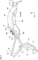
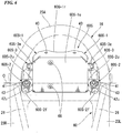
FIG. 6 is a view showing theseat attachment member 60S when seen from above the vehicle, andFIG. 7 is a side view of themotorcycle 1 in which theseat attachment member 60S and the vicinity of the attachment section thereof are enlarged. - As shown in
FIGS. 6 and7 , theseat attachment member 60S has amain body section 60S-1 formed in substantially a shallow box shape, a lower side of which is open,front protrusion sections 60S-2 fixed to regions of themain body section 60S-1 close to front end portions of left and right sidewalls through welding, andrear protrusion sections 60S-3 fixed to regions of themain body section 60S-1 close to rear end portions of the left and right sidewalls. - A regulator (regulator/rectifier) (not shown) is fastened and fixed to a lower surface side of an upper
flat wall 60S-1u of themain body section 60S-1 by abolt 66. The regulator converts alternating current power generated by a generator into direct current at a voltage of a specified voltage or less. - In addition, a pair of fastening holes 40 configured to fasten and fix a lower surface of a rear section side of the
seat 20 are formed in arear wall 60S-1r of themain body section 60S-1. The pair of fastening holes 40 are formed at positions separated in the vehicle width direction of therear wall 60S-1r. Weld nuts 39 (seeFIG. 7 ) are attached to back surface sides of the fastening holes 40 of therear wall 60S-1r. In the embodiment, the fastening holes 40 of therear wall 60S-1r and the weld nuts 39 constitute a seat fixing section to which the rear section of the occupant-seatingseat 20 is fixed. - Further, the seat fixing section constituted by the fastening holes 40 and the weld nuts 39 may be formed on another portion, for example, the
upper wall 60S-1u, as long as they are disposed at positions separated from thefront protrusion section 60S-2 in the forward/rearward direction of the vehicle body without being limited to therear wall 60S-1r of themain body section 60S-1. - The left and right
front protrusion sections 60S-2 of theseat attachment member 60S have substantially horizontalupper walls 60S-2u, and hangingwalls 60S-2f extending to be bent downward from front end portions of theupper walls 60S-2u. Insertion holes (not shown) are formed in theupper walls 60S-2u of thefront protrusion sections 60S-2, andbolts 41 configured to fix thefront protrusion sections 60S-2 to the corresponding left and rightside frame sections Rubber bushes upper walls 60S-2u of thefront protrusion sections 60S-2. Further,washers 43 overlap an upper surface of therubber bush 42u of an upper side and a lower surface of therubber bush 421 of a lower side, and the upper andlower rubber bushes side frame sections bolts 41 while theupper walls 60S-2u of thefront protrusion sections 60S-2 are sandwiched therebetween. - In the
seat attachment member 60S, portions of theupper walls 60S-2u of the left and rightfront protrusion sections 60S-2 are swingably attached to the corresponding left and rightside frame sections rubber bushes lower rubber bushes side frame sections bolts 41, and outer circumferential edge portions of the upper andlower rubber bushes upper walls 60S-2u of thefront protrusion sections 60S-2and thewashers 43. Accordingly, theseat attachment member 60S receive initial loads of the upper andlower rubber bushes rubber bushes - The left and right
front protrusion sections 60S-2 of theseat attachment member 60S are formed at left and right symmetrical positions of themain body section 60S-1. Accordingly, portions of theupper walls 60S-2u of the left and rightfront protrusion sections 60S-2 are attached to the vehicle body (theside frame sections lower rubber bushes - In the case of the embodiment, the
upper walls 60S-2u of the left and rightfront protrusion sections 60S-2 and the upper andlower rubber bushes seat attachment member 60S. - In addition, in the case of the embodiment, the
seat attachment member 60S is inclined upward toward a rear side of the vehicle body such that theupper walls 60S-1u of themain body section 60S-1 are disposed substantially along inclinations of theside frame sections front protrusion sections 60S-2 are attached to the left and rightside frame sections rubber bushes FIG. 7 . - The left and right
rear protrusion sections 60S-3 of theseat attachment member 60S haverestriction walls 60S-3a inclined upward toward a rear side of the vehicle body substantially along theupper walls 60S-1u of themain body section 60S-1. Rubber shock-absorbing members 44 (first elastic members) are attached to therestriction walls 60S-3a. The rubber shock-absorbingmembers 44 have substantially columnar load receiving sections protruding downward therestriction walls 60S-3a. - In addition, similarly, rubber shock-absorbing members 45 (second elastic members) are also attached to the hanging
walls 60S-2f of the left and rightfront protrusion sections 60S-2 of theseat attachment member 60S. The rubber shock-absorbingmembers 45 have substantially spherical load receiving sections protruding toward rear sides of the hangingwalls 60S-2f. - Here, as shown in
FIGS. 5 and7 , the swellingregions 60c of theside frame sections projections 60c-1 withfront surfaces 60c-1f standing in the vertical direction andupper surfaces 60c-1u extending substantially horizontally from upper ends of thefront surfaces 60c-1f toward a rear side of the vehicle body, and theseat attachment member 60S is attached to theupper surfaces 60c-lu of theprojections 60c-1. Specifically, as shown inFIG. 5 , fastening holes 46 are formed in theupper surfaces 60c-1u of theprojections 60c-1, and tip portions of thebolts 41 passing through thefront protrusion sections 60S-2 of theseat attachment member 60S and therubber bushes seat attachment member 60S is attached to thefront protrusion sections 60S-2 of theseat attachment member 60S in a state in which thewasher 43 disposed at a lower surface side of therubber bush 421 abuts theupper surface 60c-1u of theprojection 60c-1. - In addition, the rubber shock-absorbing
members 45 attached to the hangingwalls 60S-2f of thefront protrusion sections 60S-2 of theseat attachment member 60S abut thefront surfaces 60c-1f of theprojections 60c-1. The hangingwalls 60S-2f restrict excessive pivotal movement of theseat attachment member 60S in one direction about the portions of therubber bushes walls 60S-2f to abut thefront surfaces 60c-1f of theprojections 60c-1 via the rubber shock-absorbingmembers 45. The front surfaces 60c-1f of theprojections 60c-1 constitute a swing restriction section (a first swing restriction section, a receiving surface) configured to restrict a swing range of theseat attachment member 60S. - In addition, the swelling
regions 60c of theside frame sections sections 47 adjacent to rear sides of theprojections 60c-1, and substantially triangular raisedsections 60c-2 adjacent to rear sides of the recessedsections 47 when seen in a side view.Extension walls 48 extending toward an upper side of the rear section protrude from the raisedsections 60c-2.Upper surfaces 48u of theextension walls 48 are flatly formed, and the rubber shock-absorbingmembers 44 attached to therear protrusion sections 60S-3 of theseat attachment member 60S abut theupper surfaces 48u. Therestriction wall 60S-3a restricts excessive pivotal movement in the other direction about portions of therubber bushes seat attachment member 60S (using a pivot support point) by causing therestriction wall 60S-3a to abut theupper surfaces 48u of theextension walls 48 via the rubber shock-absorbingmembers 44. Theupper surfaces 48u of therestriction walls 60S-3a constitute a swing restriction section (a second swing restriction section, a receiving surface) configured to restrict a swing range of theseat attachment member 60S. - Further, while the rubber shock-absorbing
members 44 are attached to therestriction walls 60S-3a of therear protrusion sections 60S-3 in the embodiment, the rubber shock-absorbingmembers 44 may be attached to the vehicle body side (for example, theupper surfaces 48u of the extension walls 48). Similarly, while the rubber shock-absorbingmembers 45 are attached to the hangingwalls 60S-2f of thefront protrusion sections 60S-2 in the embodiment, the rubber shock-absorbingmembers 45 may be attached to the vehicle body side (for example, thefront surfaces 60c-1f of theprojections 60c-1 of theside frame sections -
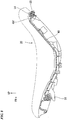
FIG. 8 is a view showing a longitudinal cross section in which a bottom section of the occupant-seatingseat 20 is cut substantially along the forward/rearward direction of the vehicle body. - In the
seat 20, a seat frame or a cushion material (not shown) is supported by abottom plate 49. An engaginghook 51 protruding toward a front side of the vehicle body in substantially an L shape extends from a lower surface of a front section side of thebottom plate 49. As shown inFIG. 4 , the engaginghook 51 is inserted into a lower side of a lockingplate 52 that bridges the left and rightseat sub-frame sections plate 52. - In addition, an
attachment flange 49f continuously extends from the rear section of thebottom plate 49, and a pair offastening bolts 54 are held at theattachment flange 49f viarubber bushes 53. Shaft sections of thefastening bolts 54 are locked into the fastening holes 40 of therear walls 60S-1r of theseat attachment member 60S and theweld nuts 39 of the back portion. - Incidentally, the upper and
lower rubber bushes front protrusion sections 60S-2 of theseat attachment member 60S at theside frame sections FIG. 9 . As shown inFIG. 9 , the upper andlower rubber bushes bolts 41 are fitted are formed in the shaft center sections, and a plurality of cutout grooves 29 (notches) are radially formed at one end surface in the axial direction abutting thewashers 43. Therubber bushes front protrusion sections 60S-2 of theseat attachment member 60S employ the same specifications including shapes (shapes and the number) of thecutout grooves 29. - When the
seat 20 is attached to the vehicle body in actuality, the engaginghook 51 at the front section side (one end side of theseat 20, first end side of the seat 20) of thebottom plate 49 of theseat 20 is locked to the lockingplate 52 of the vehicle body side, and in this state, the rear section side (another end side of theseat 20, second end side of the seat 20) of thebottom plate 49 is fastened and fixed to the rear section of themain body section 60S-1 of theseat attachment member 60S by thefastening bolts 54. Here, at the time when the shaft sections of thefastening bolts 54 are inserted into the fastening holes 40 corresponding to the rear section of theseat attachment member 60S, the shaft sections of thefastening bolts 54 are inserted into the corresponding fastening holes 40 by appropriately swinging theseat attachment member 60S at the portions of the left and rightfront protrusion sections 60S-2 while using therubber bushes seat 20 is fastened and fixed to the vehicle body side via theseat attachment member 60S by fastening thefastening bolts 54. - As described above, the seat attachment structure according to the embodiment includes the
seat attachment member 60S including thefront protrusion sections 60S-2 that are swingably attached to theside frame sections rear fender frame 60 at the front side of theseat attachment member 60S, and the seat fixing section (the fastening holes 40 and the weld nuts 39) to which the rear end portion of theseat 20 is attached at the rear side of theseat attachment member 60S. For this reason, in a state in which the engaginghook 51 of the front section side of theseat 20 is locked to the lockingplate 52 at the vehicle body side, the rear end portion side of theseat 20 can be easily fastened and fixed to therear walls 60S-1r of themain body section 60S-1 of theseat attachment member 60S by thefastening bolts 54 while an inclination attitude or position of theseat attachment member 60S is finely adjusted. Accordingly, as the seat attachment structure according to the embodiment is employed, attachment workability of theseat 20 can be improved. - In addition, in the seat attachment structure according to the embodiment, the
front surface 60c-1f of theprojection 60c-1 configured to restrict a swing range of theseat attachment member 60S and theupper surface 48u of theextension wall 48 are formed at the vehicle body side (theside frame sections seat attachment member 60S can be restricted to within an appropriate range, and excessive positional deviation of theseat attachment member 60S can be suppressed. Accordingly, as the structure is employed, attachment workability of theseat 20 can be further improved. - In particular, in the case of the seat attachment structure according to the embodiment, the rubber shock-absorbing
members front protrusion sections 60S-2 of theseat attachment member 60S and therear protrusion sections 60S-3 of the vehicle body side. For this reason, the reaction according to the swing amount of theseat attachment member 60S can be obtained by the rubber shock-absorbingmembers seat 20 to the rear section is terminated, theseat attachment member 60S can be returned to an appropriate position. Accordingly, as the configuration is employed, an attachment work of theseat 20 can be more easily performed. - In addition, in the case of the seat attachment structure, since the
seat attachment member 60S abuts theprojections 60c-1 or theextension walls 48 of the vehicle body side via the rubber shock-absorbingmembers seat attachment member 60S is abruptly swung or the like can be suppressed by elasticity of the rubber shock-absorbingmembers - In addition, in the seat attachment structure according to the embodiment, the
side frame sections front surfaces 60c-1f (the first swing restriction section) of theprojections 60c-1 configured to restrict pivotal movement of one side around the axis extending in the vehicle width direction of theseat attachment member 60S, and theupper surfaces 48u (the second swing restriction section) of theextension walls 48 configured to restrict pivotal movement of the other side around the axis of theseat attachment member 60S. For this reason, even when theseat attachment member 60S is pivoted in any one direction around the axis, excessive swinging of theseat attachment member 60S can be reliably restricted. - In particular, in the seat attachment structure according to the embodiment, the
front surfaces 60c-1f (receiving surfaces) of theprojections 60c-1 serving as the first swing restriction section and theupper surfaces 48u (receiving surfaces) of theextension walls 48 serving as the second swing restriction section are disposed in different directions around the axis at different angles. For this reason, even when theseat attachment member 60S is translated in any one direction due to load input such as attachment or the like of theseat 20, displacement of theseat attachment member 60S can be efficiently restricted by either thefront surfaces 60c-1f of theprojections 60c-1 or theupper surfaces 48u of theextension walls 48. - Further, in the seat attachment structure according to the embodiment, the
front protrusion sections 60S-2 of theseat attachment member 60S are attached to the vehicle body (theside frame sections rubber bushes cutout grooves 29 are formed in the pressure welding surfaces (for example, the pressure welding surfaces to the washers 43) of therubber bushes cutout grooves 29 of therubber bushes rubber bushes - In addition, in the seat attachment structure according to the embodiment, the
cutout grooves 29 of therubber bushes front protrusion sections 60S-2 of theseat attachment member 60S are set to the same shape (and the same number). For this reason, reaction properties of the left andright rubber bushes seat attachment member 60S can be uniformly and accurately set. - Further, the present invention is not limited to the embodiment but various design changes may be made without departing from the scope of the present invention. For example, while the front end portion side of the
seat 20 is locked to the vehicle body and the rear end portion side of theseat 20 is coupled to the vehicle body via theseat attachment member 60S in the embodiment, the rear end portion side of theseat 20 may be locked to the vehicle body and the front end portion side of theseat 20 may be coupled to the vehicle body via theseat attachment member 60S. - In addition, all vehicles on which a driver rides on the vehicle body are included as the saddle riding vehicle, and in addition to the motorcycle (including a motorized bicycle and a scooter type vehicle), a three-wheeled vehicle of a two-front-wheeled and one-rear-wheeled type or the like may also be included.
- While preferred embodiments of the invention have been described and illustrated above, it should be understood that these are exemplary of the invention and are not to be considered as limiting. Additions, omissions, substitutions, and other modifications can be made without departing from the scope of the present invention. Accordingly, the invention is not to be considered as being limited by the foregoing description, and is only limited by the scope of the appended claims.
Claims (7)
- A seat attachment structure of a saddle riding vehicle, in which, in a state a first end side of a seat (20), on which an occupant sits, in a forward/rearward direction of a vehicle body is locked to the vehicle body, a second end side of the seat (20) in the forward/rearward direction of the vehicle body is coupled to the vehicle body, the seat attachment structure of the saddle riding vehicle comprising:a seat attachment member (60S) interposed between the second end side of the seat (20) and the vehicle body and configured to couple the second end side of the seat (20) to the vehicle body,wherein the seat attachment member (60S) includes:a vehicle body-side connecting section (42u, 421, 60S-2u) swingably attached to the vehicle body while having an axis (O) extending along a vehicle width direction as a swing axis; anda seat fixing section (39, 40) disposed at a position separated from the vehicle body-side connecting section (42u, 421, 60S-2u) in the forward/rearward direction of the vehicle body and to which the second end side of the seat (20) is attached.
- The seat attachment structure of the saddle riding vehicle according to claim 1,wherein a swing restriction section (60c-1f, 48u) configured to restrict a swing range of the seat attachment member (60S) is installed at the vehicle body.
- The seat attachment structure of the saddle riding vehicle according to claim 2,wherein a first elastic member (44, 45) is provided at least at one of the swing restriction section (60c-1f, 48u) and a portion of the seat attachment member (60S) opposite to the swing restriction section (60c-1f, 48u).
- The seat attachment structure of the saddle riding vehicle according to claim 2 or 3,wherein the swing restriction section (60c-1f, 48u) includes a first swing restriction section (60c-1f) configured to restrict pivotal movement in one direction of the seat attachment member (60S) about the vehicle body-side connecting section (42u, 421, 60S-2u), and a second swing restriction section (48u) configured to restrict pivotal movement in the other direction of the seat attachment member (60S) about the vehicle body-side connecting section (42u, 421, 60S-2u).
- The seat attachment structure of the saddle riding vehicle according to claim 4,wherein the first swing restriction section (60c-1f) and the second swing restriction section (48u) are arranged to include a receiving surface that are oriented in different directions around an axis extending in the vehicle width direction with each other and that have different angles with each other.
- The seat attachment structure of the saddle riding vehicle according to any one of claims 1 to 5,wherein the vehicle body-side connecting sections (42u, 421, 60S-2u) of the seat attachment member (60S) is attached to the vehicle body via a second elastic member (42u, 421), anda notch (29) is formed in a pressure welding surface of the second elastic member (42u, 421).
- The seat attachment structure of the saddle riding vehicle according to claim 6,wherein the plurality of vehicle body-side connecting sections (42u, 421, 60S-2u) are formed on a same straight line in the vehicle width direction, andthe notches (29) formed in the second elastic members (42u, 421) of the vehicle body-side connecting sections (42u, 421, 60S-2u) are formed in the same shape.
Applications Claiming Priority (1)
| Application Number | Priority Date | Filing Date | Title |
|---|---|---|---|
| JP2016073408A JP6331157B2 (en) | 2016-03-31 | 2016-03-31 | Seat mounting structure for saddle-ride type vehicles |
Publications (2)
| Publication Number | Publication Date |
|---|---|
| EP3228528A1 true EP3228528A1 (en) | 2017-10-11 |
| EP3228528B1 EP3228528B1 (en) | 2021-04-21 |
Family
ID=58347121
Family Applications (1)
| Application Number | Title | Priority Date | Filing Date |
|---|---|---|---|
| EP17160776.5A Active EP3228528B1 (en) | 2016-03-31 | 2017-03-14 | Seat attachment structure of saddle riding vehicle |
Country Status (5)
| Country | Link |
|---|---|
| US (1) | US10308300B2 (en) |
| EP (1) | EP3228528B1 (en) |
| JP (1) | JP6331157B2 (en) |
| AU (1) | AU2017201727B2 (en) |
| CA (1) | CA2962250A1 (en) |
Families Citing this family (5)
| Publication number | Priority date | Publication date | Assignee | Title |
|---|---|---|---|---|
| JP6331157B2 (en) * | 2016-03-31 | 2018-05-30 | 本田技研工業株式会社 | Seat mounting structure for saddle-ride type vehicles |
| JP6563993B2 (en) * | 2017-09-19 | 2019-08-21 | 本田技研工業株式会社 | Saddle riding vehicle |
| CN107697203B (en) * | 2017-10-20 | 2023-12-22 | 浙江联宜电机有限公司 | Double-bending double-girder structure of scooter |
| JP7328436B2 (en) * | 2020-02-21 | 2023-08-16 | 本田技研工業株式会社 | saddle-riding vehicle |
| DE102020131460A1 (en) | 2020-11-27 | 2022-06-02 | Bayerische Motoren Werke Aktiengesellschaft | Seat device for a tilting vehicle, in particular one comprising a boxer engine |
Citations (3)
| Publication number | Priority date | Publication date | Assignee | Title |
|---|---|---|---|---|
| JPS58115478U (en) * | 1982-02-01 | 1983-08-06 | 本田技研工業株式会社 | Vehicle seat mounting device |
| JPH07246966A (en) * | 1994-03-09 | 1995-09-26 | Honda Motor Co Ltd | Seat support device for motorcycles |
| JP2009262845A (en) | 2008-04-28 | 2009-11-12 | Kawasaki Heavy Ind Ltd | Attachment structure of seat and motorcycle with the same |
Family Cites Families (20)
| Publication number | Priority date | Publication date | Assignee | Title |
|---|---|---|---|---|
| DE3822732A1 (en) * | 1987-07-06 | 1989-01-26 | Honda Motor Co Ltd | MOTORCYCLE |
| RU2097247C1 (en) * | 1996-03-14 | 1997-11-27 | Акционерное общество открытого типа "Завод им.В.А.Дегтярева" | Vehicle seat fastening device |
| JP3947297B2 (en) * | 1998-03-18 | 2007-07-18 | 本田技研工業株式会社 | Seat mounting structure for motorcycles |
| DE19841749A1 (en) * | 1998-09-11 | 2000-03-16 | Bayerische Motoren Werke Ag | Motorbike with a swiveling seat |
| JP3629999B2 (en) * | 1999-01-22 | 2005-03-16 | スズキ株式会社 | Motorcycle seat mounting structure |
| JP4116799B2 (en) * | 2002-03-08 | 2008-07-09 | 本田技研工業株式会社 | Motorcycle fuel tank support structure |
| WO2004045900A2 (en) * | 2002-11-15 | 2004-06-03 | Milsco Manufacturing Company | Vehicle seat suspension and method |
| JP4270899B2 (en) * | 2003-02-12 | 2009-06-03 | 本田技研工業株式会社 | Seat structure in saddle-ride type vehicles |
| JP4861048B2 (en) * | 2006-04-27 | 2012-01-25 | 本田技研工業株式会社 | Seat support structure |
| JP5271211B2 (en) * | 2009-09-09 | 2013-08-21 | 本田技研工業株式会社 | Seat height adjustment device for motorcycles |
| JP5683195B2 (en) * | 2010-09-30 | 2015-03-11 | 本田技研工業株式会社 | Vehicle seat support structure |
| JP6018861B2 (en) * | 2012-09-20 | 2016-11-02 | 本田技研工業株式会社 | Saddle riding vehicle |
| JP6144901B2 (en) | 2012-12-06 | 2017-06-07 | 川崎重工業株式会社 | Motorcycle |
| JP6144993B2 (en) * | 2013-08-08 | 2017-06-07 | 本田技研工業株式会社 | Saddle riding vehicle |
| JP5885770B2 (en) * | 2014-03-19 | 2016-03-15 | 本田技研工業株式会社 | Boarding detection device for saddle riding type vehicles |
| US9663168B2 (en) * | 2014-10-10 | 2017-05-30 | Kawasaki Jukogyo Kabushiki Kaisha | Straddle-type vehicle and seat structure thereof |
| JP6288524B2 (en) * | 2015-10-09 | 2018-03-07 | 本田技研工業株式会社 | Saddle riding |
| JP6331157B2 (en) * | 2016-03-31 | 2018-05-30 | 本田技研工業株式会社 | Seat mounting structure for saddle-ride type vehicles |
| US20170282749A1 (en) * | 2016-03-31 | 2017-10-05 | Honda Motor Co., Ltd. | Saddle-ride type vehicle |
| US10661848B2 (en) * | 2016-11-18 | 2020-05-26 | Ts Tech Co., Ltd. | Seat device |
-
2016
- 2016-03-31 JP JP2016073408A patent/JP6331157B2/en active Active
-
2017
- 2017-03-14 AU AU2017201727A patent/AU2017201727B2/en not_active Ceased
- 2017-03-14 EP EP17160776.5A patent/EP3228528B1/en active Active
- 2017-03-27 CA CA2962250A patent/CA2962250A1/en not_active Abandoned
- 2017-03-29 US US15/472,531 patent/US10308300B2/en active Active
Patent Citations (3)
| Publication number | Priority date | Publication date | Assignee | Title |
|---|---|---|---|---|
| JPS58115478U (en) * | 1982-02-01 | 1983-08-06 | 本田技研工業株式会社 | Vehicle seat mounting device |
| JPH07246966A (en) * | 1994-03-09 | 1995-09-26 | Honda Motor Co Ltd | Seat support device for motorcycles |
| JP2009262845A (en) | 2008-04-28 | 2009-11-12 | Kawasaki Heavy Ind Ltd | Attachment structure of seat and motorcycle with the same |
Also Published As
| Publication number | Publication date |
|---|---|
| JP6331157B2 (en) | 2018-05-30 |
| AU2017201727B2 (en) | 2019-02-21 |
| US10308300B2 (en) | 2019-06-04 |
| US20170282987A1 (en) | 2017-10-05 |
| JP2017178292A (en) | 2017-10-05 |
| EP3228528B1 (en) | 2021-04-21 |
| AU2017201727A1 (en) | 2017-10-19 |
| CA2962250A1 (en) | 2017-09-30 |
Similar Documents
| Publication | Publication Date | Title |
|---|---|---|
| EP3228528B1 (en) | Seat attachment structure of saddle riding vehicle | |
| US9878743B2 (en) | Front vehicle-body structure of vehicle | |
| US9694870B2 (en) | Motorcycle | |
| US8272656B2 (en) | Frame structure of a vehicle | |
| US10000252B2 (en) | Swingarm support structure | |
| JP4774976B2 (en) | Rear body structure of the vehicle | |
| TWI714242B (en) | Tilting vehicle | |
| JP5408189B2 (en) | Steering column support device | |
| US10279860B2 (en) | Swing arm of saddle riding vehicle | |
| EP3225525B1 (en) | Swing arm of saddle riding vehicle | |
| JP6902887B2 (en) | Manufacturing method of saddle type vehicle, step mounting member, and step mounting member | |
| EP3225514B1 (en) | Stand support structure of saddle riding vehicle | |
| JP2020045061A (en) | Steering support structure | |
| CN108528580B (en) | Pedal assembly for vehicle | |
| JP5408181B2 (en) | Steering column support device and manufacturing method thereof | |
| JP6571470B2 (en) | Steering mechanism support structure | |
| JP5429226B2 (en) | Steering column support device and manufacturing method thereof | |
| JP7487841B2 (en) | Vehicle Structure | |
| JP6510894B2 (en) | V rod bracket | |
| JP2019099001A (en) | Vehicle body frame structure of motor cycle |
Legal Events
| Date | Code | Title | Description |
|---|---|---|---|
| PUAI | Public reference made under article 153(3) epc to a published international application that has entered the european phase |
Free format text: ORIGINAL CODE: 0009012 |
|
| STAA | Information on the status of an ep patent application or granted ep patent |
Free format text: STATUS: REQUEST FOR EXAMINATION WAS MADE |
|
| 17P | Request for examination filed |
Effective date: 20170314 |
|
| AK | Designated contracting states |
Kind code of ref document: A1 Designated state(s): AL AT BE BG CH CY CZ DE DK EE ES FI FR GB GR HR HU IE IS IT LI LT LU LV MC MK MT NL NO PL PT RO RS SE SI SK SM TR |
|
| AX | Request for extension of the european patent |
Extension state: BA ME |
|
| STAA | Information on the status of an ep patent application or granted ep patent |
Free format text: STATUS: EXAMINATION IS IN PROGRESS |
|
| 17Q | First examination report despatched |
Effective date: 20180730 |
|
| REG | Reference to a national code |
Ref country code: DE Ref legal event code: R079 Ref document number: 602017036954 Country of ref document: DE Free format text: PREVIOUS MAIN CLASS: B62J0001120000 Ipc: B62J0001020000 |
|
| RIC1 | Information provided on ipc code assigned before grant |
Ipc: B62J 1/02 20060101AFI20200828BHEP |
|
| GRAP | Despatch of communication of intention to grant a patent |
Free format text: ORIGINAL CODE: EPIDOSNIGR1 |
|
| STAA | Information on the status of an ep patent application or granted ep patent |
Free format text: STATUS: GRANT OF PATENT IS INTENDED |
|
| INTG | Intention to grant announced |
Effective date: 20201020 |
|
| GRAS | Grant fee paid |
Free format text: ORIGINAL CODE: EPIDOSNIGR3 |
|
| GRAA | (expected) grant |
Free format text: ORIGINAL CODE: 0009210 |
|
| STAA | Information on the status of an ep patent application or granted ep patent |
Free format text: STATUS: THE PATENT HAS BEEN GRANTED |
|
| AK | Designated contracting states |
Kind code of ref document: B1 Designated state(s): AL AT BE BG CH CY CZ DE DK EE ES FI FR GB GR HR HU IE IS IT LI LT LU LV MC MK MT NL NO PL PT RO RS SE SI SK SM TR |
|
| REG | Reference to a national code |
Ref country code: GB Ref legal event code: FG4D |
|
| REG | Reference to a national code |
Ref country code: CH Ref legal event code: EP |
|
| REG | Reference to a national code |
Ref country code: DE Ref legal event code: R096 Ref document number: 602017036954 Country of ref document: DE Ref country code: IE Ref legal event code: FG4D |
|
| REG | Reference to a national code |
Ref country code: AT Ref legal event code: REF Ref document number: 1384353 Country of ref document: AT Kind code of ref document: T Effective date: 20210515 |
|
| REG | Reference to a national code |
Ref country code: LT Ref legal event code: MG9D |
|
| REG | Reference to a national code |
Ref country code: AT Ref legal event code: MK05 Ref document number: 1384353 Country of ref document: AT Kind code of ref document: T Effective date: 20210421 |
|
| REG | Reference to a national code |
Ref country code: NL Ref legal event code: MP Effective date: 20210421 |
|
| PG25 | Lapsed in a contracting state [announced via postgrant information from national office to epo] |
Ref country code: FI Free format text: LAPSE BECAUSE OF FAILURE TO SUBMIT A TRANSLATION OF THE DESCRIPTION OR TO PAY THE FEE WITHIN THE PRESCRIBED TIME-LIMIT Effective date: 20210421 Ref country code: LT Free format text: LAPSE BECAUSE OF FAILURE TO SUBMIT A TRANSLATION OF THE DESCRIPTION OR TO PAY THE FEE WITHIN THE PRESCRIBED TIME-LIMIT Effective date: 20210421 Ref country code: HR Free format text: LAPSE BECAUSE OF FAILURE TO SUBMIT A TRANSLATION OF THE DESCRIPTION OR TO PAY THE FEE WITHIN THE PRESCRIBED TIME-LIMIT Effective date: 20210421 Ref country code: BG Free format text: LAPSE BECAUSE OF FAILURE TO SUBMIT A TRANSLATION OF THE DESCRIPTION OR TO PAY THE FEE WITHIN THE PRESCRIBED TIME-LIMIT Effective date: 20210721 Ref country code: AT Free format text: LAPSE BECAUSE OF FAILURE TO SUBMIT A TRANSLATION OF THE DESCRIPTION OR TO PAY THE FEE WITHIN THE PRESCRIBED TIME-LIMIT Effective date: 20210421 Ref country code: NL Free format text: LAPSE BECAUSE OF FAILURE TO SUBMIT A TRANSLATION OF THE DESCRIPTION OR TO PAY THE FEE WITHIN THE PRESCRIBED TIME-LIMIT Effective date: 20210421 |
|
| PG25 | Lapsed in a contracting state [announced via postgrant information from national office to epo] |
Ref country code: IS Free format text: LAPSE BECAUSE OF FAILURE TO SUBMIT A TRANSLATION OF THE DESCRIPTION OR TO PAY THE FEE WITHIN THE PRESCRIBED TIME-LIMIT Effective date: 20210821 Ref country code: GR Free format text: LAPSE BECAUSE OF FAILURE TO SUBMIT A TRANSLATION OF THE DESCRIPTION OR TO PAY THE FEE WITHIN THE PRESCRIBED TIME-LIMIT Effective date: 20210722 Ref country code: LV Free format text: LAPSE BECAUSE OF FAILURE TO SUBMIT A TRANSLATION OF THE DESCRIPTION OR TO PAY THE FEE WITHIN THE PRESCRIBED TIME-LIMIT Effective date: 20210421 Ref country code: NO Free format text: LAPSE BECAUSE OF FAILURE TO SUBMIT A TRANSLATION OF THE DESCRIPTION OR TO PAY THE FEE WITHIN THE PRESCRIBED TIME-LIMIT Effective date: 20210721 Ref country code: PT Free format text: LAPSE BECAUSE OF FAILURE TO SUBMIT A TRANSLATION OF THE DESCRIPTION OR TO PAY THE FEE WITHIN THE PRESCRIBED TIME-LIMIT Effective date: 20210823 Ref country code: PL Free format text: LAPSE BECAUSE OF FAILURE TO SUBMIT A TRANSLATION OF THE DESCRIPTION OR TO PAY THE FEE WITHIN THE PRESCRIBED TIME-LIMIT Effective date: 20210421 Ref country code: RS Free format text: LAPSE BECAUSE OF FAILURE TO SUBMIT A TRANSLATION OF THE DESCRIPTION OR TO PAY THE FEE WITHIN THE PRESCRIBED TIME-LIMIT Effective date: 20210421 Ref country code: SE Free format text: LAPSE BECAUSE OF FAILURE TO SUBMIT A TRANSLATION OF THE DESCRIPTION OR TO PAY THE FEE WITHIN THE PRESCRIBED TIME-LIMIT Effective date: 20210421 |
|
| REG | Reference to a national code |
Ref country code: DE Ref legal event code: R097 Ref document number: 602017036954 Country of ref document: DE |
|
| PG25 | Lapsed in a contracting state [announced via postgrant information from national office to epo] |
Ref country code: SK Free format text: LAPSE BECAUSE OF FAILURE TO SUBMIT A TRANSLATION OF THE DESCRIPTION OR TO PAY THE FEE WITHIN THE PRESCRIBED TIME-LIMIT Effective date: 20210421 Ref country code: SM Free format text: LAPSE BECAUSE OF FAILURE TO SUBMIT A TRANSLATION OF THE DESCRIPTION OR TO PAY THE FEE WITHIN THE PRESCRIBED TIME-LIMIT Effective date: 20210421 Ref country code: CZ Free format text: LAPSE BECAUSE OF FAILURE TO SUBMIT A TRANSLATION OF THE DESCRIPTION OR TO PAY THE FEE WITHIN THE PRESCRIBED TIME-LIMIT Effective date: 20210421 Ref country code: DK Free format text: LAPSE BECAUSE OF FAILURE TO SUBMIT A TRANSLATION OF THE DESCRIPTION OR TO PAY THE FEE WITHIN THE PRESCRIBED TIME-LIMIT Effective date: 20210421 Ref country code: EE Free format text: LAPSE BECAUSE OF FAILURE TO SUBMIT A TRANSLATION OF THE DESCRIPTION OR TO PAY THE FEE WITHIN THE PRESCRIBED TIME-LIMIT Effective date: 20210421 Ref country code: RO Free format text: LAPSE BECAUSE OF FAILURE TO SUBMIT A TRANSLATION OF THE DESCRIPTION OR TO PAY THE FEE WITHIN THE PRESCRIBED TIME-LIMIT Effective date: 20210421 Ref country code: ES Free format text: LAPSE BECAUSE OF FAILURE TO SUBMIT A TRANSLATION OF THE DESCRIPTION OR TO PAY THE FEE WITHIN THE PRESCRIBED TIME-LIMIT Effective date: 20210421 |
|
| PLBE | No opposition filed within time limit |
Free format text: ORIGINAL CODE: 0009261 |
|
| STAA | Information on the status of an ep patent application or granted ep patent |
Free format text: STATUS: NO OPPOSITION FILED WITHIN TIME LIMIT |
|
| 26N | No opposition filed |
Effective date: 20220124 |
|
| PG25 | Lapsed in a contracting state [announced via postgrant information from national office to epo] |
Ref country code: IS Free format text: LAPSE BECAUSE OF FAILURE TO SUBMIT A TRANSLATION OF THE DESCRIPTION OR TO PAY THE FEE WITHIN THE PRESCRIBED TIME-LIMIT Effective date: 20210821 Ref country code: AL Free format text: LAPSE BECAUSE OF FAILURE TO SUBMIT A TRANSLATION OF THE DESCRIPTION OR TO PAY THE FEE WITHIN THE PRESCRIBED TIME-LIMIT Effective date: 20210421 |
|
| PG25 | Lapsed in a contracting state [announced via postgrant information from national office to epo] |
Ref country code: IT Free format text: LAPSE BECAUSE OF FAILURE TO SUBMIT A TRANSLATION OF THE DESCRIPTION OR TO PAY THE FEE WITHIN THE PRESCRIBED TIME-LIMIT Effective date: 20210421 |
|
| REG | Reference to a national code |
Ref country code: DE Ref legal event code: R084 Ref document number: 602017036954 Country of ref document: DE |
|
| PG25 | Lapsed in a contracting state [announced via postgrant information from national office to epo] |
Ref country code: MC Free format text: LAPSE BECAUSE OF FAILURE TO SUBMIT A TRANSLATION OF THE DESCRIPTION OR TO PAY THE FEE WITHIN THE PRESCRIBED TIME-LIMIT Effective date: 20210421 |
|
| REG | Reference to a national code |
Ref country code: CH Ref legal event code: PL |
|
| GBPC | Gb: european patent ceased through non-payment of renewal fee |
Effective date: 20220314 |
|
| REG | Reference to a national code |
Ref country code: BE Ref legal event code: MM Effective date: 20220331 |
|
| PG25 | Lapsed in a contracting state [announced via postgrant information from national office to epo] |
Ref country code: LU Free format text: LAPSE BECAUSE OF NON-PAYMENT OF DUE FEES Effective date: 20220314 Ref country code: LI Free format text: LAPSE BECAUSE OF NON-PAYMENT OF DUE FEES Effective date: 20220331 Ref country code: IE Free format text: LAPSE BECAUSE OF NON-PAYMENT OF DUE FEES Effective date: 20220314 Ref country code: GB Free format text: LAPSE BECAUSE OF NON-PAYMENT OF DUE FEES Effective date: 20220314 Ref country code: FR Free format text: LAPSE BECAUSE OF NON-PAYMENT OF DUE FEES Effective date: 20220331 Ref country code: CH Free format text: LAPSE BECAUSE OF NON-PAYMENT OF DUE FEES Effective date: 20220331 |
|
| PG25 | Lapsed in a contracting state [announced via postgrant information from national office to epo] |
Ref country code: BE Free format text: LAPSE BECAUSE OF NON-PAYMENT OF DUE FEES Effective date: 20220331 |
|
| PG25 | Lapsed in a contracting state [announced via postgrant information from national office to epo] |
Ref country code: HU Free format text: LAPSE BECAUSE OF FAILURE TO SUBMIT A TRANSLATION OF THE DESCRIPTION OR TO PAY THE FEE WITHIN THE PRESCRIBED TIME-LIMIT; INVALID AB INITIO Effective date: 20170314 |
|
| PG25 | Lapsed in a contracting state [announced via postgrant information from national office to epo] |
Ref country code: MK Free format text: LAPSE BECAUSE OF FAILURE TO SUBMIT A TRANSLATION OF THE DESCRIPTION OR TO PAY THE FEE WITHIN THE PRESCRIBED TIME-LIMIT Effective date: 20210421 Ref country code: CY Free format text: LAPSE BECAUSE OF FAILURE TO SUBMIT A TRANSLATION OF THE DESCRIPTION OR TO PAY THE FEE WITHIN THE PRESCRIBED TIME-LIMIT Effective date: 20210421 |
|
| PG25 | Lapsed in a contracting state [announced via postgrant information from national office to epo] |
Ref country code: MT Free format text: LAPSE BECAUSE OF FAILURE TO SUBMIT A TRANSLATION OF THE DESCRIPTION OR TO PAY THE FEE WITHIN THE PRESCRIBED TIME-LIMIT Effective date: 20210421 |
|
| PG25 | Lapsed in a contracting state [announced via postgrant information from national office to epo] |
Ref country code: TR Free format text: LAPSE BECAUSE OF FAILURE TO SUBMIT A TRANSLATION OF THE DESCRIPTION OR TO PAY THE FEE WITHIN THE PRESCRIBED TIME-LIMIT Effective date: 20210421 |
|
| PGFP | Annual fee paid to national office [announced via postgrant information from national office to epo] |
Ref country code: DE Payment date: 20260219 Year of fee payment: 10 |