EP3228489A1 - Driving support apparatus - Google Patents
Driving support apparatus Download PDFInfo
- Publication number
- EP3228489A1 EP3228489A1 EP17165341.3A EP17165341A EP3228489A1 EP 3228489 A1 EP3228489 A1 EP 3228489A1 EP 17165341 A EP17165341 A EP 17165341A EP 3228489 A1 EP3228489 A1 EP 3228489A1
- Authority
- EP
- European Patent Office
- Prior art keywords
- engine
- margin
- parameters
- support apparatus
- driving support
- Prior art date
- Legal status (The legal status is an assumption and is not a legal conclusion. Google has not performed a legal analysis and makes no representation as to the accuracy of the status listed.)
- Granted
Links
- 238000004364 calculation method Methods 0.000 claims abstract description 8
- 238000010248 power generation Methods 0.000 description 10
- 238000000034 method Methods 0.000 description 9
- 238000010586 diagram Methods 0.000 description 8
- 230000007246 mechanism Effects 0.000 description 7
- 239000000446 fuel Substances 0.000 description 6
- 230000005540 biological transmission Effects 0.000 description 5
- 230000007423 decrease Effects 0.000 description 4
- 230000005611 electricity Effects 0.000 description 4
- 230000001172 regenerating effect Effects 0.000 description 4
- 230000008901 benefit Effects 0.000 description 3
- 239000002828 fuel tank Substances 0.000 description 3
- 230000002093 peripheral effect Effects 0.000 description 3
- 230000008859 change Effects 0.000 description 2
- 238000001514 detection method Methods 0.000 description 2
- 239000003502 gasoline Substances 0.000 description 2
- 230000008569 process Effects 0.000 description 2
- 230000007704 transition Effects 0.000 description 2
- 238000002485 combustion reaction Methods 0.000 description 1
- 230000012447 hatching Effects 0.000 description 1
- 238000012544 monitoring process Methods 0.000 description 1
- 239000007858 starting material Substances 0.000 description 1
Images


Classifications
-
- B—PERFORMING OPERATIONS; TRANSPORTING
- B60—VEHICLES IN GENERAL
- B60W—CONJOINT CONTROL OF VEHICLE SUB-UNITS OF DIFFERENT TYPE OR DIFFERENT FUNCTION; CONTROL SYSTEMS SPECIALLY ADAPTED FOR HYBRID VEHICLES; ROAD VEHICLE DRIVE CONTROL SYSTEMS FOR PURPOSES NOT RELATED TO THE CONTROL OF A PARTICULAR SUB-UNIT
- B60W20/00—Control systems specially adapted for hybrid vehicles
- B60W20/40—Controlling the engagement or disengagement of prime movers, e.g. for transition between prime movers
-
- B—PERFORMING OPERATIONS; TRANSPORTING
- B60—VEHICLES IN GENERAL
- B60W—CONJOINT CONTROL OF VEHICLE SUB-UNITS OF DIFFERENT TYPE OR DIFFERENT FUNCTION; CONTROL SYSTEMS SPECIALLY ADAPTED FOR HYBRID VEHICLES; ROAD VEHICLE DRIVE CONTROL SYSTEMS FOR PURPOSES NOT RELATED TO THE CONTROL OF A PARTICULAR SUB-UNIT
- B60W10/00—Conjoint control of vehicle sub-units of different type or different function
- B60W10/24—Conjoint control of vehicle sub-units of different type or different function including control of energy storage means
- B60W10/26—Conjoint control of vehicle sub-units of different type or different function including control of energy storage means for electrical energy, e.g. batteries or capacitors
-
- B—PERFORMING OPERATIONS; TRANSPORTING
- B60—VEHICLES IN GENERAL
- B60K—ARRANGEMENT OR MOUNTING OF PROPULSION UNITS OR OF TRANSMISSIONS IN VEHICLES; ARRANGEMENT OR MOUNTING OF PLURAL DIVERSE PRIME-MOVERS IN VEHICLES; AUXILIARY DRIVES FOR VEHICLES; INSTRUMENTATION OR DASHBOARDS FOR VEHICLES; ARRANGEMENTS IN CONNECTION WITH COOLING, AIR INTAKE, GAS EXHAUST OR FUEL SUPPLY OF PROPULSION UNITS IN VEHICLES
- B60K35/00—Arrangement of adaptations of instruments
-
- B60K35/22—
-
- B60K35/28—
-
- B—PERFORMING OPERATIONS; TRANSPORTING
- B60—VEHICLES IN GENERAL
- B60K—ARRANGEMENT OR MOUNTING OF PROPULSION UNITS OR OF TRANSMISSIONS IN VEHICLES; ARRANGEMENT OR MOUNTING OF PLURAL DIVERSE PRIME-MOVERS IN VEHICLES; AUXILIARY DRIVES FOR VEHICLES; INSTRUMENTATION OR DASHBOARDS FOR VEHICLES; ARRANGEMENTS IN CONNECTION WITH COOLING, AIR INTAKE, GAS EXHAUST OR FUEL SUPPLY OF PROPULSION UNITS IN VEHICLES
- B60K6/00—Arrangement or mounting of plural diverse prime-movers for mutual or common propulsion, e.g. hybrid propulsion systems comprising electric motors and internal combustion engines ; Control systems therefor, i.e. systems controlling two or more prime movers, or controlling one of these prime movers and any of the transmission, drive or drive units Informative references: mechanical gearings with secondary electric drive F16H3/72; arrangements for handling mechanical energy structurally associated with the dynamo-electric machine H02K7/00; machines comprising structurally interrelated motor and generator parts H02K51/00; dynamo-electric machines not otherwise provided for in H02K see H02K99/00
- B60K6/20—Arrangement or mounting of plural diverse prime-movers for mutual or common propulsion, e.g. hybrid propulsion systems comprising electric motors and internal combustion engines ; Control systems therefor, i.e. systems controlling two or more prime movers, or controlling one of these prime movers and any of the transmission, drive or drive units Informative references: mechanical gearings with secondary electric drive F16H3/72; arrangements for handling mechanical energy structurally associated with the dynamo-electric machine H02K7/00; machines comprising structurally interrelated motor and generator parts H02K51/00; dynamo-electric machines not otherwise provided for in H02K see H02K99/00 the prime-movers consisting of electric motors and internal combustion engines, e.g. HEVs
- B60K6/42—Arrangement or mounting of plural diverse prime-movers for mutual or common propulsion, e.g. hybrid propulsion systems comprising electric motors and internal combustion engines ; Control systems therefor, i.e. systems controlling two or more prime movers, or controlling one of these prime movers and any of the transmission, drive or drive units Informative references: mechanical gearings with secondary electric drive F16H3/72; arrangements for handling mechanical energy structurally associated with the dynamo-electric machine H02K7/00; machines comprising structurally interrelated motor and generator parts H02K51/00; dynamo-electric machines not otherwise provided for in H02K see H02K99/00 the prime-movers consisting of electric motors and internal combustion engines, e.g. HEVs characterised by the architecture of the hybrid electric vehicle
- B60K6/44—Series-parallel type
- B60K6/442—Series-parallel switching type
-
- B—PERFORMING OPERATIONS; TRANSPORTING
- B60—VEHICLES IN GENERAL
- B60L—PROPULSION OF ELECTRICALLY-PROPELLED VEHICLES; SUPPLYING ELECTRIC POWER FOR AUXILIARY EQUIPMENT OF ELECTRICALLY-PROPELLED VEHICLES; ELECTRODYNAMIC BRAKE SYSTEMS FOR VEHICLES IN GENERAL; MAGNETIC SUSPENSION OR LEVITATION FOR VEHICLES; MONITORING OPERATING VARIABLES OF ELECTRICALLY-PROPELLED VEHICLES; ELECTRIC SAFETY DEVICES FOR ELECTRICALLY-PROPELLED VEHICLES
- B60L50/00—Electric propulsion with power supplied within the vehicle
- B60L50/10—Electric propulsion with power supplied within the vehicle using propulsion power supplied by engine-driven generators, e.g. generators driven by combustion engines
- B60L50/16—Electric propulsion with power supplied within the vehicle using propulsion power supplied by engine-driven generators, e.g. generators driven by combustion engines with provision for separate direct mechanical propulsion
-
- B—PERFORMING OPERATIONS; TRANSPORTING
- B60—VEHICLES IN GENERAL
- B60W—CONJOINT CONTROL OF VEHICLE SUB-UNITS OF DIFFERENT TYPE OR DIFFERENT FUNCTION; CONTROL SYSTEMS SPECIALLY ADAPTED FOR HYBRID VEHICLES; ROAD VEHICLE DRIVE CONTROL SYSTEMS FOR PURPOSES NOT RELATED TO THE CONTROL OF A PARTICULAR SUB-UNIT
- B60W10/00—Conjoint control of vehicle sub-units of different type or different function
- B60W10/04—Conjoint control of vehicle sub-units of different type or different function including control of propulsion units
- B60W10/06—Conjoint control of vehicle sub-units of different type or different function including control of propulsion units including control of combustion engines
-
- B—PERFORMING OPERATIONS; TRANSPORTING
- B60—VEHICLES IN GENERAL
- B60W—CONJOINT CONTROL OF VEHICLE SUB-UNITS OF DIFFERENT TYPE OR DIFFERENT FUNCTION; CONTROL SYSTEMS SPECIALLY ADAPTED FOR HYBRID VEHICLES; ROAD VEHICLE DRIVE CONTROL SYSTEMS FOR PURPOSES NOT RELATED TO THE CONTROL OF A PARTICULAR SUB-UNIT
- B60W10/00—Conjoint control of vehicle sub-units of different type or different function
- B60W10/04—Conjoint control of vehicle sub-units of different type or different function including control of propulsion units
- B60W10/08—Conjoint control of vehicle sub-units of different type or different function including control of propulsion units including control of electric propulsion units, e.g. motors or generators
-
- B—PERFORMING OPERATIONS; TRANSPORTING
- B60—VEHICLES IN GENERAL
- B60W—CONJOINT CONTROL OF VEHICLE SUB-UNITS OF DIFFERENT TYPE OR DIFFERENT FUNCTION; CONTROL SYSTEMS SPECIALLY ADAPTED FOR HYBRID VEHICLES; ROAD VEHICLE DRIVE CONTROL SYSTEMS FOR PURPOSES NOT RELATED TO THE CONTROL OF A PARTICULAR SUB-UNIT
- B60W20/00—Control systems specially adapted for hybrid vehicles
- B60W20/10—Controlling the power contribution of each of the prime movers to meet required power demand
-
- B—PERFORMING OPERATIONS; TRANSPORTING
- B60—VEHICLES IN GENERAL
- B60W—CONJOINT CONTROL OF VEHICLE SUB-UNITS OF DIFFERENT TYPE OR DIFFERENT FUNCTION; CONTROL SYSTEMS SPECIALLY ADAPTED FOR HYBRID VEHICLES; ROAD VEHICLE DRIVE CONTROL SYSTEMS FOR PURPOSES NOT RELATED TO THE CONTROL OF A PARTICULAR SUB-UNIT
- B60W20/00—Control systems specially adapted for hybrid vehicles
- B60W20/20—Control strategies involving selection of hybrid configuration, e.g. selection between series or parallel configuration
-
- B—PERFORMING OPERATIONS; TRANSPORTING
- B60—VEHICLES IN GENERAL
- B60W—CONJOINT CONTROL OF VEHICLE SUB-UNITS OF DIFFERENT TYPE OR DIFFERENT FUNCTION; CONTROL SYSTEMS SPECIALLY ADAPTED FOR HYBRID VEHICLES; ROAD VEHICLE DRIVE CONTROL SYSTEMS FOR PURPOSES NOT RELATED TO THE CONTROL OF A PARTICULAR SUB-UNIT
- B60W50/00—Details of control systems for road vehicle drive control not related to the control of a particular sub-unit, e.g. process diagnostic or vehicle driver interfaces
- B60W50/08—Interaction between the driver and the control system
- B60W50/14—Means for informing the driver, warning the driver or prompting a driver intervention
-
- B60K2360/167—
-
- B60K2360/168—
-
- B60K2360/169—
-
- B60K2360/174—
-
- B—PERFORMING OPERATIONS; TRANSPORTING
- B60—VEHICLES IN GENERAL
- B60W—CONJOINT CONTROL OF VEHICLE SUB-UNITS OF DIFFERENT TYPE OR DIFFERENT FUNCTION; CONTROL SYSTEMS SPECIALLY ADAPTED FOR HYBRID VEHICLES; ROAD VEHICLE DRIVE CONTROL SYSTEMS FOR PURPOSES NOT RELATED TO THE CONTROL OF A PARTICULAR SUB-UNIT
- B60W50/00—Details of control systems for road vehicle drive control not related to the control of a particular sub-unit, e.g. process diagnostic or vehicle driver interfaces
- B60W50/08—Interaction between the driver and the control system
- B60W50/14—Means for informing the driver, warning the driver or prompting a driver intervention
- B60W2050/146—Display means
-
- B—PERFORMING OPERATIONS; TRANSPORTING
- B60—VEHICLES IN GENERAL
- B60W—CONJOINT CONTROL OF VEHICLE SUB-UNITS OF DIFFERENT TYPE OR DIFFERENT FUNCTION; CONTROL SYSTEMS SPECIALLY ADAPTED FOR HYBRID VEHICLES; ROAD VEHICLE DRIVE CONTROL SYSTEMS FOR PURPOSES NOT RELATED TO THE CONTROL OF A PARTICULAR SUB-UNIT
- B60W2510/00—Input parameters relating to a particular sub-units
- B60W2510/24—Energy storage means
- B60W2510/242—Energy storage means for electrical energy
- B60W2510/244—Charge state
-
- B—PERFORMING OPERATIONS; TRANSPORTING
- B60—VEHICLES IN GENERAL
- B60W—CONJOINT CONTROL OF VEHICLE SUB-UNITS OF DIFFERENT TYPE OR DIFFERENT FUNCTION; CONTROL SYSTEMS SPECIALLY ADAPTED FOR HYBRID VEHICLES; ROAD VEHICLE DRIVE CONTROL SYSTEMS FOR PURPOSES NOT RELATED TO THE CONTROL OF A PARTICULAR SUB-UNIT
- B60W2510/00—Input parameters relating to a particular sub-units
- B60W2510/24—Energy storage means
- B60W2510/242—Energy storage means for electrical energy
- B60W2510/246—Temperature
-
- B—PERFORMING OPERATIONS; TRANSPORTING
- B60—VEHICLES IN GENERAL
- B60W—CONJOINT CONTROL OF VEHICLE SUB-UNITS OF DIFFERENT TYPE OR DIFFERENT FUNCTION; CONTROL SYSTEMS SPECIALLY ADAPTED FOR HYBRID VEHICLES; ROAD VEHICLE DRIVE CONTROL SYSTEMS FOR PURPOSES NOT RELATED TO THE CONTROL OF A PARTICULAR SUB-UNIT
- B60W2540/00—Input parameters relating to occupants
- B60W2540/10—Accelerator pedal position
-
- B—PERFORMING OPERATIONS; TRANSPORTING
- B60—VEHICLES IN GENERAL
- B60Y—INDEXING SCHEME RELATING TO ASPECTS CROSS-CUTTING VEHICLE TECHNOLOGY
- B60Y2200/00—Type of vehicle
- B60Y2200/90—Vehicles comprising electric prime movers
- B60Y2200/92—Hybrid vehicles
-
- Y—GENERAL TAGGING OF NEW TECHNOLOGICAL DEVELOPMENTS; GENERAL TAGGING OF CROSS-SECTIONAL TECHNOLOGIES SPANNING OVER SEVERAL SECTIONS OF THE IPC; TECHNICAL SUBJECTS COVERED BY FORMER USPC CROSS-REFERENCE ART COLLECTIONS [XRACs] AND DIGESTS
- Y02—TECHNOLOGIES OR APPLICATIONS FOR MITIGATION OR ADAPTATION AGAINST CLIMATE CHANGE
- Y02T—CLIMATE CHANGE MITIGATION TECHNOLOGIES RELATED TO TRANSPORTATION
- Y02T10/00—Road transport of goods or passengers
- Y02T10/60—Other road transportation technologies with climate change mitigation effect
- Y02T10/62—Hybrid vehicles
-
- Y—GENERAL TAGGING OF NEW TECHNOLOGICAL DEVELOPMENTS; GENERAL TAGGING OF CROSS-SECTIONAL TECHNOLOGIES SPANNING OVER SEVERAL SECTIONS OF THE IPC; TECHNICAL SUBJECTS COVERED BY FORMER USPC CROSS-REFERENCE ART COLLECTIONS [XRACs] AND DIGESTS
- Y02—TECHNOLOGIES OR APPLICATIONS FOR MITIGATION OR ADAPTATION AGAINST CLIMATE CHANGE
- Y02T—CLIMATE CHANGE MITIGATION TECHNOLOGIES RELATED TO TRANSPORTATION
- Y02T10/00—Road transport of goods or passengers
- Y02T10/60—Other road transportation technologies with climate change mitigation effect
- Y02T10/70—Energy storage systems for electromobility, e.g. batteries
-
- Y—GENERAL TAGGING OF NEW TECHNOLOGICAL DEVELOPMENTS; GENERAL TAGGING OF CROSS-SECTIONAL TECHNOLOGIES SPANNING OVER SEVERAL SECTIONS OF THE IPC; TECHNICAL SUBJECTS COVERED BY FORMER USPC CROSS-REFERENCE ART COLLECTIONS [XRACs] AND DIGESTS
- Y02—TECHNOLOGIES OR APPLICATIONS FOR MITIGATION OR ADAPTATION AGAINST CLIMATE CHANGE
- Y02T—CLIMATE CHANGE MITIGATION TECHNOLOGIES RELATED TO TRANSPORTATION
- Y02T10/00—Road transport of goods or passengers
- Y02T10/80—Technologies aiming to reduce greenhouse gasses emissions common to all road transportation technologies
- Y02T10/84—Data processing systems or methods, management, administration
-
- Y—GENERAL TAGGING OF NEW TECHNOLOGICAL DEVELOPMENTS; GENERAL TAGGING OF CROSS-SECTIONAL TECHNOLOGIES SPANNING OVER SEVERAL SECTIONS OF THE IPC; TECHNICAL SUBJECTS COVERED BY FORMER USPC CROSS-REFERENCE ART COLLECTIONS [XRACs] AND DIGESTS
- Y10—TECHNICAL SUBJECTS COVERED BY FORMER USPC
- Y10S—TECHNICAL SUBJECTS COVERED BY FORMER USPC CROSS-REFERENCE ART COLLECTIONS [XRACs] AND DIGESTS
- Y10S903/00—Hybrid electric vehicles, HEVS
- Y10S903/902—Prime movers comprising electrical and internal combustion motors
- Y10S903/903—Prime movers comprising electrical and internal combustion motors having energy storing means, e.g. battery, capacitor
Definitions
- the present invention relates to a driving support apparatus for supporting driving of a vehicle.
- a hybrid vehicle including an engine and a motor travels with an EV traveling mode in which only the motor is driven to travel, a series traveling mode in which the vehicle travels with the driving force of the motor while driving the engine to generate electricity, and a parallel traveling mode in which the vehicle travels with the driving force of the engine and the motor. Those modes are switched as necessary.
- JP-A-2013-014219 discloses a technique in which when the setting (EV travel priority mode) for maintaining the engine stopped state in order to reduce the fuel consumption amount and the exhaust gas emission amount is performed, even if the state of charge (SOC) of the battery is short, the engine is stopped as intended by the driver and avoiding imparting a feeling of strangeness to the driver.
- the engine is started when the vehicle is in a predetermined state.
- the predetermined state is, for example, a case where the state of charge of the battery is low, a case where the required output becomes larger, a case where the battery voltage drops, a case where the battery temperature deviates from a predetermined range, or the like.
- the state of charge is displayed on the instrument panel or the like of the vehicle, and the required output is linked with the driving operation of the driver (the depression amount of the accelerator pedal). Therefore, the driver easily grasps the state of them and the required output. When the engine is started due to these parameters, there is a low possibility that the driver feels discomfort.
- the present invention has been made in view of the above-described matters, and an object of the present invention is to enable a driver to grasp start timing of an engine in a hybrid vehicle.
- a driving support apparatus for a hybrid vehicle includes an engine and a motor, in which the engine starts running when any one of parameters indicating a state of the hybrid vehicle reaches an engine start threshold set for the parameters.
- the driving support apparatus includes a current value acquiring section that acquires current values of the parameters, a margin calculation section that calculates margin levels for the current values of the parameters for keeping the engine stopping using the current values of the parameters and the engine start thresholds, and an output section that outputs the smallest margin level of the calculated margin levels.
- the driver there is an advantage for the driver to easily know the margin level for keeping the EV traveling without starting the engine because the margin level for each of a plurality of parameters related to the starting of the engine is calculated and the smallest margin level is presented to the driver. It is thought that, in a case where there is a possibility that the engine starts due to the parameters other than the parameters including the state of charge and the required output which the driver is conventionally able to know, the driver can grasp factors of starting the engine , thereby improving the convenience.
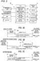
- FIG. 1 is an explanatory diagram showing a configuration of a hybrid vehicle 12 equipped with a driving support apparatus 10 according to an embodiment.
- FIG. 2 is a block diagram showing a peripheral configuration of the driving support apparatus 10.
- the hybrid vehicle 12 includes a traveling system 20, a power generation system 30, and an ECU 70.
- the traveling system 20 is a driving mechanism of the hybrid vehicle 12 and includes front wheels 21, rear wheels 22, a motor 23, an inverter 24, an engine 25, a transmission mechanism 26 for transmitting rotation of an output shaft 23A of the motor 23 and rotation of an output shaft 25A of the engine 25 to the front wheels 21, a fuel tank 40, and a battery 50.
- the front wheels 21 and the rear wheels 22 are each constituted by two wheels paired in the vehicle width direction.
- the front wheels 21 are drive wheels of the motor 23 and the engine 25.
- the motor 23 is driven by using the electric power accumulated in the battery 50, and outputs the rotational force (torque) from the output shaft 23A.
- the motor 23 may perform regenerative operation when decelerating the hybrid vehicle 12 (for example, when the accelerator pedal is released) and perform regenerative power generation.
- the electric power generated by the regenerative power generation is supplied to the battery 50 via the inverter 24 to charge the battery 50.
- the inverter 24 adjusts the electric power of the battery 50 according to the driver's request and supplies it to the motor 23.
- the driver's request includes, for example, the operation of an accelerator pedal, a brake pedal, a shift lever (not shown) or the like, and a vehicle speed measured by a vehicle speed sensor, etc.
- the ECU 70 described later calculates a required output from the driver's request and controls the inverter 24 based on the calculated required output.
- the engine 25 is driven by combusting the fuel supplied from the fuel tank 40 in the combustion chamber.
- the engine 25 is a reciprocating engine using gasoline as a fuel.
- the driving of the engine 25 is controlled by the ECU 70 described later.
- the transmission mechanism 26 transmits the rotation of the output shaft 23A of the motor 23 to the front wheels 21 and the rotation of the output shaft 25A of the engine 25 to the front wheels 21.
- the transmission mechanism 26 includes a clutch device 27.
- the clutch device 27 includes a pair of clutch plates 27A and 27B and a driving portion 27C with which the clutch plates 27A and 27B comes into contact with each other and the contact state is released.
- the clutch plate 27A rotates integrally with the output shaft 25A of the engine 25.
- the clutch plate 27B rotates integrally with the output shaft 23A of the motor 23.
- the clutch plates 27A and 27B are brought into contact with each other by the driving portion 27C, the clutch plates 27A, 27B rotate integrally with each other.
- the rotation of the output shaft 25A of the engine 25 is transmitted to the front wheels 21.
- the clutch plates 27A and 27B are separated from each other by the driving portion 27C, the rotation of the output shaft 25A of the engine 25 is not transmitted to the front wheels 21.
- the drive unit 27C is controlled by the ECU 70 described later.
- the fuel tank 40 stores fuel (gasoline, for example) which is a power source of the engine 25.
- the battery 50 accumulates electric power which is a power source of the motor 23. Charging of the battery 50 may be performed by power generation by the generator 31, regenerative power generation by the motor 23, supply of external power from a charge connector (not shown) provided in the vehicle body of the hybrid vehicle 12.
- a BMU (Battery Monitoring Unit) 50A is connected to the battery 50.
- the BMU 50A detects the voltage and temperature of the battery 50, the input/output current of the battery 50, and the like, and detects the state of the battery 50 including the state of charge (SOC).
- the BMU 50A transmits the state of the battery 50 (state of charge, battery voltage, battery temperature, etc.) to the ECU 70.
- the battery 50 is configured by connecting a plurality of battery cells in series.
- Each battery cell is provided with a voltmeter and a thermometer, and measures the cell voltage and cell temperature of each battery cell.
- the voltmeter and the temperature may be provided for each cell unit composed of a predetermined number of battery cells.
- the measured values of the voltmeter and the thermometer are input to the BMU 50A.
- an ammeter is provided between the battery 50 and a device operating under the supply of electric power from the battery 50 (the motor 23 in the present embodiment), and measures the output current from the battery 50.
- the measured value of the ammeter is input to the BMU 50A.
- the power generation system 30 is a mechanism for charging the battery 50, and includes an engine 25, a generator 31, and an inverter 24.
- the rotation of the output shaft 25A of the engine 25 is transmitted to the rotation shaft 31A of the generator 31 via the second transmission mechanism 32.
- the rotary shaft 31A rotates by receiving the rotation of the output shaft 25A of the engine 25 and the generator 31 generates electricity.
- the generator 31 is connected to the inverter 24, and the AC power generated by the generator 31 is converted into DC power by the inverter 24 and accumulated in the battery 50.
- the AC power generated by the generator 31 is directly used for driving the motor 23.
- the generated power of the generator 31 is supplied to the motor 23 after the frequency is appropriately converted by the inverter 24.
- the generator 31 also functions as an electric motor (starter) when starting the engine 25.
- starter When starting the engine 25, the ECU 70 controls the inverter 24 to drive the generator 31.
- the rotating shaft 31A rotates. Since the rotary shaft 31A is connected to the output shaft 25A of the engine 25 via the second transmission mechanism 32, when the generator 31 is driven and the rotary shaft 31A rotates, it is possible to rotate the output shaft 25A of the engine 25.
- the display unit 76 displays various kinds of information indicating the state of the hybrid vehicle 12 so that the driver may visually recognize it.
- the margin level for keeping the EV traveling without starting the engine is displayed during the EV travel priority mode described later.
- the display unit 76 is provided, for example, in an instrument panel of a driver's seat, and displays the state of charge of the battery 50, the traveling speed of the hybrid vehicle 12, etc. in addition to the margin up to the above-described engine start.
- the operation unit 77 receives various settings relating to the traveling of the hybrid vehicle 12.
- the operation section 77 includes, for example, a switch or the like provided in the periphery of the instrument panel of the driver's seat or the steering wheel or the like.
- the operation unit 77 receives a setting operation for transition to the EV travel priority mode.
- the EV travel priority mode is a mode in which traveling in the EV traveling mode described later is continued as much as possible. Since the engine 25 is stopped in the EV traveling mode, it is effective in minimizing fuel consumption, or useful in controlling emission of exhaust gas, for example.
- a SOC priority mode in which the state of charge of the battery 50 is maintained close to 100% for example, a charge priority mode in which the battery 50 is actively charged to increase the state of charge, or the like may be provided.
- the ECU 70 is a control unit that entirely controls the hybrid vehicle 12.
- the ECU 70 includes a CPU, a ROM for storing a control program and the like, a RAM as an operation area of the control program, an EEPROM for rewritably holding various data, an interface unit for communicating with a peripheral circuit, and the like.
- the ECU 70 perform functions as a current value acquiring section 700, a drive control section 702, a margin calculation section 704, and an output section 706 by executing the control program by the CPU.
- the current value acquiring section 700 acquires the current value of the parameter group used when switching between the three driving modes described later.
- the parameter group acquired by the present value acquiring section 700 includes at least one of a state of charge of the battery 50 of the hybrid vehicle 12, a request output to the hybrid vehicle 12, and a battery voltage of the battery 50, and so on. Besides this, for example, the battery temperature of the battery 50 may be included in the parameter group.
- the required output to the hybrid vehicle 12 is obtained, for example, by obtaining the detection value of the accelerator opening degree sensor 71 indicating the operation amount of the accelerator pedal.
- the state of charge of the battery 50, the battery voltage, the battery temperature, and the like can be acquired from the BMU 50A.
- the battery voltage and the battery temperature may be obtained individually for all the battery cells constituting the battery 50, or may be an average value of the values of these battery cells.
- the drive control section 702 controls each unit of the hybrid vehicle 12, for example, the motor 23, the engine 25, the generator 31, the drive unit 27C of the clutch device 27, and the like, based on the parameter group acquired by the current value acquisition section 700.
- the drive control section 702 appropriately switches the three driving modes of the hybrid vehicle 12 including:
- the engine 25 In an EV travelling mode, the engine 25 is stopped and the vehicle runs by rotating the axle with the driving force of the motor 23.
- the electric power supplied to the motor 23 in the EV travelling mode is the electric power accumulated in the battery 50.
- a series travelling mode the vehicle is driven by rotating the axle with the driving force of the motor 23 while driving the generator 31 with the engine 25.
- the electric power supplied to the motor 23 in the series traveling mode is the electric power accumulated in the battery 50 and generated electric power generated by the generator 31.
- the vehicle may transit to the series traveling mode.
- the vehicle In a parallel travelling mode, the vehicle is driven by rotating the axle with the driving force of the engine 25 and the driving force of the motor 23.
- the vehicle may transit to the parallel traveling mode.
- the parallel traveling mode it is possible to transmit the driving force of the engine 25 to the generator 31 to generate electricity. That is, the driving force of the engine 25 is distributable to both the traveling and the electric power generation.
- the hybrid vehicle 12 starts traveling in the EV traveling mode, and thereafter, when any one of the parameter groups showing the state of the hybrid vehicle 12 reaches an engine start threshold set for the parameters, and the engine 25 is started and shifts to the series traveling mode or the parallel traveling mode.
- the drive control section 702 changes the engine start threshold set for each parameter in accordance with the setting operation on the operation unit 77.
- the engine start threshold value for the state of charge of the battery 50 is lowered so as not to start the engine 25 until the state of charge reaches the lowered engine start threshold. Further, the engine start threshold for the required output is increased so as not to start the engine 25 until a larger output is requested. Similarly, the other engine start thresholds for the other parameters are changed so that the engine 25 is difficult to start up.
- the margin calculation section 704 calculates the margin level for keeping the EV traveling without starting the engine 25 by using the current value of each parameter and the engine start threshold value during the EV traveling mode in which the hybrid vehicle 12 is traveling without running engine. The larger the margin is, the more difficult the engine 25 starts. The smaller the margin is, the easier the engine 25 starts.
- the margin calculating section 704 calculates the margin level by dividing a difference between a current value of each parameter and an engine starting threshold by a difference between a value most distant from the engine starting threshold within a possible value range and the engine starting threshold.
- margin level to start the engine in each parameter is calculated by the following equation 1.
- Margin level current value ⁇ engine starting threshold / parameter value most distant from the engine starting threshold ⁇ engine starting threshold
- FIGS. 3A to 3C are diagrams schematically showing a margin calculation method by the margin calculation section 704.
- FIG. 3A shows the case where the parameter is the state of charge of the battery 50.
- the state of charge is within a range from 0% to 100%, and the engine starting threshold is 25%.
- the state of charge reaches 25% or less, the engine 25 starts to start power generation.
- the value furthest from the engine starting threshold value within the possible value range is "state of charge 100%".
- FIG. 3B shows a case where the parameter is the request output.
- the detection value of the accelerator opening degree sensor 71 is used as the required output. It is assumed that the value of the accelerator opening sensor value is within 1 V to 5 V and the larger the accelerator operation amount is, the larger the voltage value becomes. That is, the larger the required output is, the larger the voltage value becomes. Further, it is assumed that the engine start threshold is 3.5 V. When the voltage value becomes 3.5 V or more, the engine 25 starts and power generation or wheel driving is started. In this case, the value furthest from the engine starting threshold value within the possible value range is "accelerator opening degree sensor value 1 V".
- the margin level is 20%.
- FIG. 3C shows a case where the parameter is the battery voltage of the battery 50. It is assumed that the value of the battery voltage is within 2.0 V to 4.0 V, and the engine start threshold is 2.5 V. The engine 25 starts and starts generating electricity when the battery voltage becomes 2.5 V or less. In this case, the value furthest from the engine starting threshold value among the possible value range is "battery voltage 4.0 V".
- the margin level is 4%.
- the output section 706 outputs the smallest value among the margin levels calculated for the respective parameters.
- the output part 706 outputs "4%" as the margin level for keeping the EV traveling without starting engine 25 because 4% as the margin level relating to the battery voltage is the smallest value.
- the reason for outputting the smallest value of the margin levels is that the engine 25 is started when any one of the parameters reaches the engine starting threshold. That is, the margin level for keeping the EV traveling without starting the engine 25 of the hybrid vehicle 12 is indicated by the smallest value among the margin levels calculated for the plurality of parameters.
- the output section 706 notifies the driver of the margin level by displaying it on the display unit 76.
- the output form of the margin level on the output section 706 is not limited to display, but various modes such as conventional ways including sound notification may be applied.
- FIGS. 4A and 4B are diagrams showing an example of a method of displaying the margin level on the display unit 76.
- FIG. 4A shows a display when the margin level is about 70%
- FIG. 4B shows a display when the margin level is about 10%.
- the display unit 76 may include a margin level display 80, a traveling speed display 7602, a motor rotation number display 7604, a state of charge indication (not shown), and the like.
- FIGS. 4A and 4B shows the priority mode set via the operation unit 77.
- the priority mode display 7606 is configured by icons indicating priority modes that are selectable via the operation unit 77.
- the EV travel priority mode is selected, and the icon C marked "EV" is lit.
- the margin level display 80 may be displayed only when the EV travel priority mode is selected or may be always displayed irrespective of the setting of the priority mode.
- an area 806 corresponding to the margin level is displayed with a color different from that of other areas.
- the area 806 is indicated by hatching.
- the margin level is the maximum value
- the area 806 is maximized
- the margin level is the minimum value
- the area 806 is minimized, an area of which is substantially zero. That is, the upper end 802 of the vertically elongated rectangular indicator corresponds to "margin level 100%" and the lower end 804 corresponds to "margin level 0%”.
- a height of the area 806 from the lower end 804 of the indicator corresponds to the margin level.
- the height of the area 806 from the lower end 804 is about seven tenth in FIG. 4 and about one tenth in FIG. 4B .
- the margin for keeping the EV traveling without starting the engine decreases. It is thought that the engine start timing can be intuitively notified to the driver with the display of the margin level display 80.
- the margin level may be displayed using not only a rectangular indicator as shown in FIGS. 4A and 4B but also a circle or a fan-shaped indicator such as a fuel gauge.
- a kind of the parameters which has been used for calculating the margin level displayed as the area 806 in the margin level display 80 may be displayed. That is, a kind of the parameters having the lowest margin level may be displayed. In this case, the driver may perform the driving operation while paying attention to the parameters, and it is thought that it may be possible to avoid reducing the margin level.
- a kind of the parameter having the smallest margin level may change during traveling. For example, this case may occur when the margin level of the state of charge is the lowest of all and the margin level of the state of charge is displayed, the operation amount of the accelerator pedal increases, the margin level of the required output decreases, and the margin level of the required output becomes the lowest of all parameters, for example.
- the change of the kind of the parameter having the minimum margin may be notified to the driver by voice sound, display or the like. This may motivate the driver to suppress the engine startup. That is, according to the above example, the driver may take measures, for example, by suppressing the operation amount of the accelerator pedal and increasing the margin level of the required output so as not to start the engine.
- FIG. 5 is a flowchart showing a processing procedure of the driving support apparatus 10.
- step S 500 When the setting operation to the operation section 77 is performed to set the EV travel priority mode (step S 500), the drive control section 702 changes the engine start thresholds of the parameter group. With the changing of the threshold, the engine 25 becomes hard to start (step S502).
- the current value acquiring section 700 acquires the current value of the parameter group including state of charge of the battery 50 in the hybrid vehicle 12, the required output of the hybrid vehicle 12, and a battery voltage of the battery 50 (step S504).
- Margin calculation section 704 uses the current value of each parameter and the engine start threshold to calculate the margin level for keeping the EV traveling without starting the engine 25 for each parameter (step S506).
- the output section 706 outputs the smallest value among the margin levels calculated for each parameter as margin level of the hybrid vehicle for keeping the EV traveling without starting the engine 25 (step S508).
- the margin level is 0% at step S508, that is, the engine 25 is starting immediately, the margin level of 0% is displayed.
- Step S510 If any of the parameter group does not reach the engine start threshold (Step S510: No), the EV mode is maintained without starting the engine 25 (step S 512), the process returns to step S500, and repeats the processing subsequent to the step S500.
- Step S510 Yes
- the drive control section 702 starts the engine 25 and make a mode transition to the series traveling mode or the parallel traveling mode (Step S 514).
- Step S516: No the drive control section 702 continues the running of the engine 25 (step S 518).
- step S516: Yes the engine 25 is stopped and the hybrid vehicle transits to to the EV traveling mode (step S520). Then, the process returns to step S500 to repeat the processing subsequent to the step S500.
- the driver to easily know the margin level for keeping the EV traveling without starting the engine 25 because the margin level for each of a plurality of parameters related to the starting of the engine 25 is calculated and the smallest margin level is presented to the driver. It is thought that, in a case where there is a possibility that the engine 25 starts due to the parameters other than the parameters including the state of charge and the required output which the driver is conventionally able to know, the driver can grasp factors of starting the engine 25, thereby improving the convenience.
- the driving support apparatus 10 a plural kinds of parameters having different numerical ranges and different engine start thresholds are compared with each other at the same scale. There is advantage that the driver can quickly know the margin level.
- the driver can intuitively know the margin level even during driving operation, thereby the convenience is improved.
Abstract
Description
- The present invention relates to a driving support apparatus for supporting driving of a vehicle.
- Conventionally, a hybrid vehicle including an engine and a motor travels with an EV traveling mode in which only the motor is driven to travel, a series traveling mode in which the vehicle travels with the driving force of the motor while driving the engine to generate electricity, and a parallel traveling mode in which the vehicle travels with the driving force of the engine and the motor. Those modes are switched as necessary.
- A technique which enables changing the priority of such traveling modes by the operation of a driver has been proposed.
- For example,
JP-A-2013-014219
Conventionally, even when the EV travel priority mode is set, the engine is started when the vehicle is in a predetermined state. The predetermined state is, for example, a case where the state of charge of the battery is low, a case where the required output becomes larger, a case where the battery voltage drops, a case where the battery temperature deviates from a predetermined range, or the like. - Of these parameters, for example, the state of charge is displayed on the instrument panel or the like of the vehicle, and the required output is linked with the driving operation of the driver (the depression amount of the accelerator pedal). Therefore, the driver easily grasps the state of them and the required output. When the engine is started due to these parameters, there is a low possibility that the driver feels discomfort.
- On the other hand, when the engine is started due to a parameter such as the battery voltage and battery temperature that the driver cannot grasp the state of them, the driver cannot grasp the cause of starting the engine and may feel uncomfortable.
- The present invention has been made in view of the above-described matters, and an object of the present invention is to enable a driver to grasp start timing of an engine in a hybrid vehicle.
- According to an aspect of the invention, a driving support apparatus for a hybrid vehicle includes an engine and a motor, in which the engine starts running when any one of parameters indicating a state of the hybrid vehicle reaches an engine start threshold set for the parameters. The driving support apparatus includes a current value acquiring section that acquires current values of the parameters, a margin calculation section that calculates margin levels for the current values of the parameters for keeping the engine stopping using the current values of the parameters and the engine start thresholds, and an output section that outputs the smallest margin level of the calculated margin levels.
- According to the above configuration, there is an advantage for the driver to easily know the margin level for keeping the EV traveling without starting the engine because the margin level for each of a plurality of parameters related to the starting of the engine is calculated and the smallest margin level is presented to the driver. It is thought that, in a case where there is a possibility that the engine starts due to the parameters other than the parameters including the state of charge and the required output which the driver is conventionally able to know, the driver can grasp factors of starting the engine , thereby improving the convenience.
-
-
FIG. 1 is an explanatory diagram showing a configuration of ahybrid vehicle 12 according to an embodiment. -
FIG. 2 is a block diagram showing a peripheral configuration of a driving support apparatus. -
FIGS. 3A to 3C are diagrams schematically showing a margin calculating method by a margin calculating section 704. -
FIGS. 4A and 4B are diagrams showing examples of a method of displaying the margin level on the display unit. -
FIG. 5 is a flowchart showing a processing procedure of the driving support apparatus. - Preferred embodiments of a driving support apparatus according to the present invention will be described in detail below with reference to the accompanying drawings.
-
FIG. 1 is an explanatory diagram showing a configuration of ahybrid vehicle 12 equipped with adriving support apparatus 10 according to an embodiment.FIG. 2 is a block diagram showing a peripheral configuration of thedriving support apparatus 10. As shown inFIG. 1 , thehybrid vehicle 12 includes atraveling system 20, apower generation system 30, and an ECU 70. Thetraveling system 20 is a driving mechanism of thehybrid vehicle 12 and includesfront wheels 21,rear wheels 22, amotor 23, aninverter 24, anengine 25, atransmission mechanism 26 for transmitting rotation of anoutput shaft 23A of themotor 23 and rotation of anoutput shaft 25A of theengine 25 to thefront wheels 21, afuel tank 40, and abattery 50. - The
front wheels 21 and therear wheels 22 are each constituted by two wheels paired in the vehicle width direction. In the present embodiment, thefront wheels 21 are drive wheels of themotor 23 and theengine 25. - The
motor 23 is driven by using the electric power accumulated in thebattery 50, and outputs the rotational force (torque) from theoutput shaft 23A. Themotor 23 may perform regenerative operation when decelerating the hybrid vehicle 12 (for example, when the accelerator pedal is released) and perform regenerative power generation. The electric power generated by the regenerative power generation is supplied to thebattery 50 via theinverter 24 to charge thebattery 50. - The
inverter 24 adjusts the electric power of thebattery 50 according to the driver's request and supplies it to themotor 23. The driver's request includes, for example, the operation of an accelerator pedal, a brake pedal, a shift lever (not shown) or the like, and a vehicle speed measured by a vehicle speed sensor, etc. The ECU 70 described later calculates a required output from the driver's request and controls theinverter 24 based on the calculated required output. - The
engine 25 is driven by combusting the fuel supplied from thefuel tank 40 in the combustion chamber. As an example, theengine 25 is a reciprocating engine using gasoline as a fuel. The driving of theengine 25 is controlled by the ECU 70 described later. - The
transmission mechanism 26 transmits the rotation of theoutput shaft 23A of themotor 23 to thefront wheels 21 and the rotation of theoutput shaft 25A of theengine 25 to thefront wheels 21. Thetransmission mechanism 26 includes aclutch device 27. Theclutch device 27 includes a pair ofclutch plates clutch plates - The
clutch plate 27A rotates integrally with theoutput shaft 25A of theengine 25. Theclutch plate 27B rotates integrally with theoutput shaft 23A of themotor 23. When theclutch plates clutch plates output shaft 25A of theengine 25 is transmitted to thefront wheels 21. When theclutch plates output shaft 25A of theengine 25 is not transmitted to thefront wheels 21. The drive unit 27C is controlled by the ECU 70 described later. - The
fuel tank 40 stores fuel (gasoline, for example) which is a power source of theengine 25. Thebattery 50 accumulates electric power which is a power source of themotor 23. Charging of thebattery 50 may be performed by power generation by thegenerator 31, regenerative power generation by themotor 23, supply of external power from a charge connector (not shown) provided in the vehicle body of thehybrid vehicle 12. A BMU (Battery Monitoring Unit) 50A is connected to thebattery 50. TheBMU 50A detects the voltage and temperature of thebattery 50, the input/output current of thebattery 50, and the like, and detects the state of thebattery 50 including the state of charge (SOC). TheBMU 50A transmits the state of the battery 50 (state of charge, battery voltage, battery temperature, etc.) to theECU 70. - More specifically, the
battery 50 is configured by connecting a plurality of battery cells in series. Each battery cell is provided with a voltmeter and a thermometer, and measures the cell voltage and cell temperature of each battery cell. The voltmeter and the temperature may be provided for each cell unit composed of a predetermined number of battery cells. The measured values of the voltmeter and the thermometer are input to theBMU 50A. - In addition, an ammeter is provided between the
battery 50 and a device operating under the supply of electric power from the battery 50 (themotor 23 in the present embodiment), and measures the output current from thebattery 50. The measured value of the ammeter is input to theBMU 50A. - The
power generation system 30 is a mechanism for charging thebattery 50, and includes anengine 25, agenerator 31, and aninverter 24. - The rotation of the
output shaft 25A of theengine 25 is transmitted to therotation shaft 31A of thegenerator 31 via thesecond transmission mechanism 32. When thegenerator 31 becomes ready for power generation under the control of theECU 70, therotary shaft 31A rotates by receiving the rotation of theoutput shaft 25A of theengine 25 and thegenerator 31 generates electricity. Thegenerator 31 is connected to theinverter 24, and the AC power generated by thegenerator 31 is converted into DC power by theinverter 24 and accumulated in thebattery 50. - Further, in the series traveling mode described later, the AC power generated by the
generator 31 is directly used for driving themotor 23. In this case, the generated power of thegenerator 31 is supplied to themotor 23 after the frequency is appropriately converted by theinverter 24. - The
generator 31 also functions as an electric motor (starter) when starting theengine 25. When starting theengine 25, theECU 70 controls theinverter 24 to drive thegenerator 31. As thegenerator 31 is driven, therotating shaft 31A rotates. Since therotary shaft 31A is connected to theoutput shaft 25A of theengine 25 via thesecond transmission mechanism 32, when thegenerator 31 is driven and therotary shaft 31A rotates, it is possible to rotate theoutput shaft 25A of theengine 25. - The
display unit 76 displays various kinds of information indicating the state of thehybrid vehicle 12 so that the driver may visually recognize it. In the present embodiment, the margin level for keeping the EV traveling without starting the engine is displayed during the EV travel priority mode described later. - The
display unit 76 is provided, for example, in an instrument panel of a driver's seat, and displays the state of charge of thebattery 50, the traveling speed of thehybrid vehicle 12, etc. in addition to the margin up to the above-described engine start. - The
operation unit 77 receives various settings relating to the traveling of thehybrid vehicle 12. Theoperation section 77 includes, for example, a switch or the like provided in the periphery of the instrument panel of the driver's seat or the steering wheel or the like. - In the present embodiment, the
operation unit 77 receives a setting operation for transition to the EV travel priority mode. The EV travel priority mode is a mode in which traveling in the EV traveling mode described later is continued as much as possible. Since theengine 25 is stopped in the EV traveling mode, it is effective in minimizing fuel consumption, or useful in controlling emission of exhaust gas, for example. - Further, as the other priority mode that may be set by the
operation unit 77, for example, a SOC priority mode in which the state of charge of thebattery 50 is maintained close to 100%, a charge priority mode in which thebattery 50 is actively charged to increase the state of charge, or the like may be provided. - The
ECU 70 is a control unit that entirely controls thehybrid vehicle 12. - The
ECU 70 includes a CPU, a ROM for storing a control program and the like, a RAM as an operation area of the control program, an EEPROM for rewritably holding various data, an interface unit for communicating with a peripheral circuit, and the like. - The
ECU 70 perform functions as a currentvalue acquiring section 700, adrive control section 702, a margin calculation section 704, and anoutput section 706 by executing the control program by the CPU. - The current
value acquiring section 700 acquires the current value of the parameter group used when switching between the three driving modes described later. - The parameter group acquired by the present
value acquiring section 700 includes at least one of a state of charge of thebattery 50 of thehybrid vehicle 12, a request output to thehybrid vehicle 12, and a battery voltage of thebattery 50, and so on. Besides this, for example, the battery temperature of thebattery 50 may be included in the parameter group. - The required output to the
hybrid vehicle 12 is obtained, for example, by obtaining the detection value of the acceleratoropening degree sensor 71 indicating the operation amount of the accelerator pedal. - Further, the state of charge of the
battery 50, the battery voltage, the battery temperature, and the like can be acquired from theBMU 50A. The battery voltage and the battery temperature may be obtained individually for all the battery cells constituting thebattery 50, or may be an average value of the values of these battery cells. - The
drive control section 702 controls each unit of thehybrid vehicle 12, for example, themotor 23, theengine 25, thegenerator 31, the drive unit 27C of theclutch device 27, and the like, based on the parameter group acquired by the currentvalue acquisition section 700. - The
drive control section 702 appropriately switches the three driving modes of thehybrid vehicle 12 including: - 1. EV traveling mode;
- 2. Series traveling mode;
- 3. Parallel traveling mode,
- In an EV travelling mode, the
engine 25 is stopped and the vehicle runs by rotating the axle with the driving force of themotor 23. The electric power supplied to themotor 23 in the EV travelling mode is the electric power accumulated in thebattery 50. - In a series travelling mode, the vehicle is driven by rotating the axle with the driving force of the
motor 23 while driving thegenerator 31 with theengine 25. The electric power supplied to themotor 23 in the series traveling mode is the electric power accumulated in thebattery 50 and generated electric power generated by thegenerator 31. - For example, when the state of charge of the
battery 50 decreases or when the required output becomes equal to or higher than the predetermined value at the time of low speed, the vehicle may transit to the series traveling mode. - In a parallel travelling mode, the vehicle is driven by rotating the axle with the driving force of the
engine 25 and the driving force of themotor 23. - In particular, when the efficiency of the axle drive by the
engine 25 is high, such as at high speed, the vehicle may transit to the parallel traveling mode. In the parallel traveling mode, it is possible to transmit the driving force of theengine 25 to thegenerator 31 to generate electricity. That is, the driving force of theengine 25 is distributable to both the traveling and the electric power generation. - Only the
motor 23 is driven in the EV travelling mode. Themotor 23 and theengine 25 are driven in the series travelling mode and the parallel travelling mode. Generally, thehybrid vehicle 12 starts traveling in the EV traveling mode, and thereafter, when any one of the parameter groups showing the state of thehybrid vehicle 12 reaches an engine start threshold set for the parameters, and theengine 25 is started and shifts to the series traveling mode or the parallel traveling mode. - The
drive control section 702 changes the engine start threshold set for each parameter in accordance with the setting operation on theoperation unit 77. - For example, when the EV travel priority mode is set, the engine start threshold value for the state of charge of the
battery 50 is lowered so as not to start theengine 25 until the state of charge reaches the lowered engine start threshold. Further, the engine start threshold for the required output is increased so as not to start theengine 25 until a larger output is requested. Similarly, the other engine start thresholds for the other parameters are changed so that theengine 25 is difficult to start up. - The margin calculation section 704 calculates the margin level for keeping the EV traveling without starting the
engine 25 by using the current value of each parameter and the engine start threshold value during the EV traveling mode in which thehybrid vehicle 12 is traveling without running engine. The larger the margin is, the more difficult theengine 25 starts. The smaller the margin is, the easier theengine 25 starts. - The margin calculating section 704 calculates the margin level by dividing a difference between a current value of each parameter and an engine starting threshold by a difference between a value most distant from the engine starting threshold within a possible value range and the engine starting threshold.
- That is, the margin level to start the engine in each parameter is calculated by the following equation 1.

-
FIGS. 3A to 3C are diagrams schematically showing a margin calculation method by the margin calculation section 704. -
FIG. 3A shows the case where the parameter is the state of charge of thebattery 50. In this case, it is assumed that the state of charge is within a range from 0% to 100%, and the engine starting threshold is 25%. When the state of charge reaches 25% or less, theengine 25 starts to start power generation. In this case, the value furthest from the engine starting threshold value within the possible value range is "state ofcharge 100%". - Assuming that the current value of the state of charge is 30%, the margin level is calculated using the formula (1) as follow:

-
FIG. 3B shows a case where the parameter is the request output. In the present embodiment, the detection value of the acceleratoropening degree sensor 71 is used as the required output. It is assumed that the value of the accelerator opening sensor value is within 1 V to 5 V and the larger the accelerator operation amount is, the larger the voltage value becomes. That is, the larger the required output is, the larger the voltage value becomes. Further, it is assumed that the engine start threshold is 3.5 V. When the voltage value becomes 3.5 V or more, theengine 25 starts and power generation or wheel driving is started. In this case, the value furthest from the engine starting threshold value within the possible value range is "accelerator openingdegree sensor value 1 V". - Assuming that the current value of the request output is 3 V, the margin level is calculated using the formula (1) as follow:

- The margin level is 20%.
-
FIG. 3C shows a case where the parameter is the battery voltage of thebattery 50. It is assumed that the value of the battery voltage is within 2.0 V to 4.0 V, and the engine start threshold is 2.5 V. Theengine 25 starts and starts generating electricity when the battery voltage becomes 2.5 V or less. In this case, the value furthest from the engine starting threshold value among the possible value range is "battery voltage 4.0 V". - Assuming that the current value of the battery voltage is 2.56 V, the margin level is calculated using the formula (1) as follow:

- The margin level is 4%.
- Returning to
FIG. 2 , theoutput section 706 outputs the smallest value among the margin levels calculated for the respective parameters. In the example ofFIGS. 3A to 3C , theoutput part 706 outputs "4%" as the margin level for keeping the EV traveling without startingengine 25 because 4% as the margin level relating to the battery voltage is the smallest value. - The reason for outputting the smallest value of the margin levels is that the
engine 25 is started when any one of the parameters reaches the engine starting threshold. That is, the margin level for keeping the EV traveling without starting theengine 25 of thehybrid vehicle 12 is indicated by the smallest value among the margin levels calculated for the plurality of parameters. - In the present embodiment, the
output section 706 notifies the driver of the margin level by displaying it on thedisplay unit 76. The output form of the margin level on theoutput section 706 is not limited to display, but various modes such as conventional ways including sound notification may be applied. -
FIGS. 4A and 4B are diagrams showing an example of a method of displaying the margin level on thedisplay unit 76. -
FIG. 4A shows a display when the margin level is about 70%, andFIG. 4B shows a display when the margin level is about 10%. - The
display unit 76 may include amargin level display 80, a travelingspeed display 7602, a motorrotation number display 7604, a state of charge indication (not shown), and the like. -
FIGS. 4A and 4B shows the priority mode set via theoperation unit 77. Thepriority mode display 7606 is configured by icons indicating priority modes that are selectable via theoperation unit 77. In the example ofFIG. 4A , the EV travel priority mode is selected, and the icon C marked "EV" is lit. - The
margin level display 80 may be displayed only when the EV travel priority mode is selected or may be always displayed irrespective of the setting of the priority mode. - In the
margin level display 80 ofFIGS. 4A and 4B , anarea 806 corresponding to the margin level is displayed with a color different from that of other areas. InFIGS. 4A and 4B , thearea 806 is indicated by hatching. When the margin level is the maximum value, thearea 806 is maximized, and when the margin level is the minimum value, thearea 806 is minimized, an area of which is substantially zero. That is, theupper end 802 of the vertically elongated rectangular indicator corresponds to "margin level 100%" and thelower end 804 corresponds to "margin level 0%". A height of thearea 806 from thelower end 804 of the indicator corresponds to the margin level. The height of thearea 806 from thelower end 804 is about seven tenth inFIG. 4 and about one tenth inFIG. 4B . - As the area of the
area 806 decreases, the margin for keeping the EV traveling without starting the engine decreases. It is thought that the engine start timing can be intuitively notified to the driver with the display of themargin level display 80. - The margin level may be displayed using not only a rectangular indicator as shown in
FIGS. 4A and 4B but also a circle or a fan-shaped indicator such as a fuel gauge. - A kind of the parameters which has been used for calculating the margin level displayed as the
area 806 in themargin level display 80 may be displayed. That is, a kind of the parameters having the lowest margin level may be displayed. In this case, the driver may perform the driving operation while paying attention to the parameters, and it is thought that it may be possible to avoid reducing the margin level. - There is a case where a kind of the parameter having the smallest margin level may change during traveling. For example, this case may occur when the margin level of the state of charge is the lowest of all and the margin level of the state of charge is displayed, the operation amount of the accelerator pedal increases, the margin level of the required output decreases, and the margin level of the required output becomes the lowest of all parameters, for example. In this case, the change of the kind of the parameter having the minimum margin may be notified to the driver by voice sound, display or the like. This may motivate the driver to suppress the engine startup. That is, according to the above example, the driver may take measures, for example, by suppressing the operation amount of the accelerator pedal and increasing the margin level of the required output so as not to start the engine.
-
FIG. 5 is a flowchart showing a processing procedure of the drivingsupport apparatus 10. - In the flowchart of
FIG. 5 , it is assumed that the margin level for keeping the EV traveling without starting the engine is displayed only when the EV travel priority mode is set. It is assumed that, in the initial state, theengine 25 is not running and thehybrid vehicle 12 travels in the EV traveling mode. - When the setting operation to the
operation section 77 is performed to set the EV travel priority mode (step S 500), thedrive control section 702 changes the engine start thresholds of the parameter group. With the changing of the threshold, theengine 25 becomes hard to start (step S502). - The current
value acquiring section 700 acquires the current value of the parameter group including state of charge of thebattery 50 in thehybrid vehicle 12, the required output of thehybrid vehicle 12, and a battery voltage of the battery 50 (step S504). - Margin calculation section 704 uses the current value of each parameter and the engine start threshold to calculate the margin level for keeping the EV traveling without starting the
engine 25 for each parameter (step S506). - Then, the
output section 706 outputs the smallest value among the margin levels calculated for each parameter as margin level of the hybrid vehicle for keeping the EV traveling without starting the engine 25 (step S508). When the margin level is 0% at step S508, that is, theengine 25 is starting immediately, the margin level of 0% is displayed. - If any of the parameter group does not reach the engine start threshold (Step S510: No), the EV mode is maintained without starting the engine 25 (step S 512), the process returns to step S500, and repeats the processing subsequent to the step S500.
- Also, if any one of the parameter group reaches the engine start threshold (Step S510: Yes), the
drive control section 702 starts theengine 25 and make a mode transition to the series traveling mode or the parallel traveling mode (Step S 514). - Until the parameter having reached the engine start threshold reaches an engine stop threshold in step S 510 (Step S516: No), the
drive control section 702 continues the running of the engine 25 (step S 518). When the parameter reaches the engine stop threshold (step S516: Yes), theengine 25 is stopped and the hybrid vehicle transits to to the EV traveling mode (step S520). Then, the process returns to step S500 to repeat the processing subsequent to the step S500. - As described above, according to the driving
support apparatus 10 in the embodiment, there is an advantage for the driver to easily know the margin level for keeping the EV traveling without starting theengine 25 because the margin level for each of a plurality of parameters related to the starting of theengine 25 is calculated and the smallest margin level is presented to the driver. It is thought that, in a case where there is a possibility that theengine 25 starts due to the parameters other than the parameters including the state of charge and the required output which the driver is conventionally able to know, the driver can grasp factors of starting theengine 25, thereby improving the convenience. - According to the driving
support apparatus 10, a plural kinds of parameters having different numerical ranges and different engine start thresholds are compared with each other at the same scale. There is advantage that the driver can quickly know the margin level. - Further, according to the driving
support apparatus 10, it is thought that the driver can intuitively know the margin level even during driving operation, thereby the convenience is improved.
Claims (6)
- A driving support apparatus for a hybrid vehicle including an engine (25) and a motor (2), in which the engine (25) starts running when any one of parameters indicating a state of the hybrid vehicle reaches an engine start threshold set for the parameters, the driving support apparatus comprising:a current value acquiring section (700) that acquires current values of the parameters;a margin calculation section (704) that calculates margin levels for the current values of the parameters for keeping the engine (25) stopping using the current values of the parameters and the engine start thresholds; andan output section (704) that outputs the smallest margin level of the calculated margin levels.
- The driving support apparatus according to claim 1, wherein the margin calculating section (704) calculates one of the margin levels by dividing a differences between one of the current values of the parameters and a corresponding engine starting threshold by a difference between a value most distant from the corresponding engine starting threshold within a possible value range of the one of the current values and the corresponding engine starting threshold.
- The driving support apparatus according to claim 1 or 2, further comprising:a display unit (76) that includes a display area in which an area corresponding to the smallest margin level is displayed with a color difference from that of the other regions.
- The driving support apparatus according to claim 3, wherein when the smallest margin level is the maximum value, the area has the maximum area, and
when the smallest margin level is the minimum value, the area is substantially zero. - The driving support apparatus according to any one of claims 1 to 4, wherein the parameters include at least one of a state of charge of a battery of the hybrid vehicle, a value of required output to the hybrid vehicle, a voltage of the battery, a temperature of the battery;
- The driving support apparatus according to any one of claims 1 to 5, wherein the output unit (706) outputs a notification to a driver of the hybrid vehicle when the parameter corresponding to the smallest margin level changes during traveling.
Applications Claiming Priority (1)
| Application Number | Priority Date | Filing Date | Title |
|---|---|---|---|
| JP2016077851A JP6693245B2 (en) | 2016-04-08 | 2016-04-08 | Driving support device |
Publications (2)
| Publication Number | Publication Date |
|---|---|
| EP3228489A1 true EP3228489A1 (en) | 2017-10-11 |
| EP3228489B1 EP3228489B1 (en) | 2019-01-02 |
Family
ID=58530405
Family Applications (1)
| Application Number | Title | Priority Date | Filing Date |
|---|---|---|---|
| EP17165341.3A Active EP3228489B1 (en) | 2016-04-08 | 2017-04-06 | Driving support apparatus |
Country Status (4)
| Country | Link |
|---|---|
| US (1) | US10358126B2 (en) |
| EP (1) | EP3228489B1 (en) |
| JP (1) | JP6693245B2 (en) |
| CN (1) | CN107415931B (en) |
Families Citing this family (4)
| Publication number | Priority date | Publication date | Assignee | Title |
|---|---|---|---|---|
| US10857991B2 (en) | 2018-03-08 | 2020-12-08 | Ford Global Technologies, Llc | Hybrid vehicle engine start/stop system |
| JP7410451B2 (en) * | 2018-08-02 | 2024-01-10 | 三菱自動車工業株式会社 | Hybrid vehicle display device |
| CN110696615B (en) * | 2019-10-10 | 2020-10-30 | 浙江吉利汽车研究院有限公司 | Method and system for displaying power meter of hybrid electric vehicle |
| WO2023157608A1 (en) * | 2022-02-15 | 2023-08-24 | 三菱自動車工業株式会社 | Support system |
Citations (5)
| Publication number | Priority date | Publication date | Assignee | Title |
|---|---|---|---|---|
| US20090125173A1 (en) * | 2007-11-08 | 2009-05-14 | Toyota Jidosha Kabushiki Kaisha | Hybrid vehicle with internal combustion engine and electric motor installed |
| DE102008060265A1 (en) * | 2008-12-03 | 2010-06-10 | Dr. Ing. H.C. F. Porsche Aktiengesellschaft | Display device for a hybrid vehicle |
| JP2013014219A (en) | 2011-07-04 | 2013-01-24 | Toyota Motor Corp | Control device of vehicle |
| US20130038439A1 (en) * | 2011-08-08 | 2013-02-14 | Toyota Jidosha Kabushiki Kaisha | Vehicle status display apparatus of hybrid vehicle |
| JP2013154716A (en) * | 2012-01-27 | 2013-08-15 | Toyota Motor Corp | Driving state display device of hybrid vehicle |
Family Cites Families (5)
| Publication number | Priority date | Publication date | Assignee | Title |
|---|---|---|---|---|
| US20090024382A1 (en) * | 2005-03-03 | 2009-01-22 | Wolvaardt Barend P | Language information system |
| JP4155321B2 (en) * | 2006-09-25 | 2008-09-24 | トヨタ自動車株式会社 | Hybrid vehicle display device, hybrid vehicle, and hybrid vehicle display method |
| US7898405B2 (en) * | 2008-03-25 | 2011-03-01 | Ford Global Technologies, Llc | Vehicle information display and method |
| JP5223822B2 (en) * | 2009-09-11 | 2013-06-26 | トヨタ自動車株式会社 | Display device and hybrid vehicle including the same |
| US20130091694A1 (en) * | 2011-10-18 | 2013-04-18 | Fuel Motion Inc. | Conversion kit for a hybrid electric drive vehicle |
-
2016
- 2016-04-08 JP JP2016077851A patent/JP6693245B2/en active Active
-
2017
- 2017-04-06 EP EP17165341.3A patent/EP3228489B1/en active Active
- 2017-04-07 US US15/482,083 patent/US10358126B2/en active Active
- 2017-04-07 CN CN201710224093.XA patent/CN107415931B/en active Active
Patent Citations (5)
| Publication number | Priority date | Publication date | Assignee | Title |
|---|---|---|---|---|
| US20090125173A1 (en) * | 2007-11-08 | 2009-05-14 | Toyota Jidosha Kabushiki Kaisha | Hybrid vehicle with internal combustion engine and electric motor installed |
| DE102008060265A1 (en) * | 2008-12-03 | 2010-06-10 | Dr. Ing. H.C. F. Porsche Aktiengesellschaft | Display device for a hybrid vehicle |
| JP2013014219A (en) | 2011-07-04 | 2013-01-24 | Toyota Motor Corp | Control device of vehicle |
| US20130038439A1 (en) * | 2011-08-08 | 2013-02-14 | Toyota Jidosha Kabushiki Kaisha | Vehicle status display apparatus of hybrid vehicle |
| JP2013154716A (en) * | 2012-01-27 | 2013-08-15 | Toyota Motor Corp | Driving state display device of hybrid vehicle |
Also Published As
| Publication number | Publication date |
|---|---|
| JP6693245B2 (en) | 2020-05-13 |
| JP2017185965A (en) | 2017-10-12 |
| US20170291598A1 (en) | 2017-10-12 |
| CN107415931B (en) | 2020-06-23 |
| CN107415931A (en) | 2017-12-01 |
| EP3228489B1 (en) | 2019-01-02 |
| US10358126B2 (en) | 2019-07-23 |
Similar Documents
| Publication | Publication Date | Title |
|---|---|---|
| EP3228489B1 (en) | Driving support apparatus | |
| JP6156419B2 (en) | vehicle | |
| EP2191997B1 (en) | Hybrid vehicle, informing method for hybrid vehicle, and computer readable recording medium having recorded thereon program for causing computer to execute the informing method | |
| EP3100924B1 (en) | Method and apparatus for controlling plug-in hybrid electric vehicle, as well as computer-readable medium | |
| JP6149806B2 (en) | Hybrid vehicle | |
| US20140195137A1 (en) | Internal combustion engine control apparatus and internal combustion engine control method | |
| KR20130045235A (en) | Vehicle status display apparatus of hybrid vehicle | |
| JP6414112B2 (en) | Display device | |
| JP2014201246A (en) | Hybrid vehicle | |
| US10836276B2 (en) | Display device | |
| JP2015205673A (en) | Hybrid-vehicular control apparatus | |
| JP2009027772A (en) | Device and method for indicating remaining power of battery | |
| JP2012091757A (en) | Display unit | |
| WO2014167413A1 (en) | Hybrid vehicle | |
| JP2017100469A (en) | Device for controlling hybrid vehicle | |
| JP2012106672A (en) | Hybrid vehicle | |
| CN111542448B (en) | Fuel consumption display control method and fuel consumption display control system | |
| JP2019156109A (en) | Vehicle control system | |
| KR20210027157A (en) | Display system, vehicle, and method of display of status of secondary battery | |
| JP2021040367A (en) | vehicle | |
| JP6720654B2 (en) | Clutch durability determination system, vehicle and clutch durability determination method | |
| JP2021003984A (en) | Vehicle system and hybrid vehicle | |
| JP2019035679A (en) | Charging rate calculation device | |
| JP6361299B2 (en) | Hybrid vehicle | |
| JP2019018691A (en) | Controller for hybrid vehicle |
Legal Events
| Date | Code | Title | Description |
|---|---|---|---|
| PUAI | Public reference made under article 153(3) epc to a published international application that has entered the european phase |
Free format text: ORIGINAL CODE: 0009012 |
|
| STAA | Information on the status of an ep patent application or granted ep patent |
Free format text: STATUS: REQUEST FOR EXAMINATION WAS MADE |
|
| 17P | Request for examination filed |
Effective date: 20170506 |
|
| AK | Designated contracting states |
Kind code of ref document: A1 Designated state(s): AL AT BE BG CH CY CZ DE DK EE ES FI FR GB GR HR HU IE IS IT LI LT LU LV MC MK MT NL NO PL PT RO RS SE SI SK SM TR |
|
| AX | Request for extension of the european patent |
Extension state: BA ME |
|
| GRAP | Despatch of communication of intention to grant a patent |
Free format text: ORIGINAL CODE: EPIDOSNIGR1 |
|
| STAA | Information on the status of an ep patent application or granted ep patent |
Free format text: STATUS: GRANT OF PATENT IS INTENDED |
|
| RIC1 | Information provided on ipc code assigned before grant |
Ipc: B60W 20/10 20160101ALI20180628BHEP Ipc: B60W 10/06 20060101ALI20180628BHEP Ipc: B60K 6/44 20071001AFI20180628BHEP Ipc: B60W 10/08 20060101ALI20180628BHEP Ipc: B60W 50/14 20120101ALI20180628BHEP |
|
| INTG | Intention to grant announced |
Effective date: 20180716 |
|
| GRAS | Grant fee paid |
Free format text: ORIGINAL CODE: EPIDOSNIGR3 |
|
| GRAA | (expected) grant |
Free format text: ORIGINAL CODE: 0009210 |
|
| STAA | Information on the status of an ep patent application or granted ep patent |
Free format text: STATUS: THE PATENT HAS BEEN GRANTED |
|
| AK | Designated contracting states |
Kind code of ref document: B1 Designated state(s): AL AT BE BG CH CY CZ DE DK EE ES FI FR GB GR HR HU IE IS IT LI LT LU LV MC MK MT NL NO PL PT RO RS SE SI SK SM TR |
|
| REG | Reference to a national code |
Ref country code: GB Ref legal event code: FG4D |
|
| REG | Reference to a national code |
Ref country code: CH Ref legal event code: EP Ref country code: AT Ref legal event code: REF Ref document number: 1083908 Country of ref document: AT Kind code of ref document: T Effective date: 20190115 |
|
| REG | Reference to a national code |
Ref country code: IE Ref legal event code: FG4D |
|
| REG | Reference to a national code |
Ref country code: DE Ref legal event code: R096 Ref document number: 602017001634 Country of ref document: DE |
|
| REG | Reference to a national code |
Ref country code: CH Ref legal event code: PK Free format text: BERICHTIGUNGEN |
|
| RIC2 | Information provided on ipc code assigned after grant |
Ipc: B60W 10/08 20060101ALI20180628BHEP Ipc: B60K 6/44 20071001AFI20180628BHEP Ipc: B60W 10/06 20060101ALI20180628BHEP Ipc: B60W 50/14 20120101ALI20180628BHEP Ipc: B60W 20/10 20160101ALI20180628BHEP |
|
| REG | Reference to a national code |
Ref country code: NL Ref legal event code: MP Effective date: 20190102 |
|
| REG | Reference to a national code |
Ref country code: LT Ref legal event code: MG4D |
|
| REG | Reference to a national code |
Ref country code: AT Ref legal event code: MK05 Ref document number: 1083908 Country of ref document: AT Kind code of ref document: T Effective date: 20190102 |
|
| PG25 | Lapsed in a contracting state [announced via postgrant information from national office to epo] |
Ref country code: NL Free format text: LAPSE BECAUSE OF FAILURE TO SUBMIT A TRANSLATION OF THE DESCRIPTION OR TO PAY THE FEE WITHIN THE PRESCRIBED TIME-LIMIT Effective date: 20190102 |
|
| RAP2 | Party data changed (patent owner data changed or rights of a patent transferred) |
Owner name: MITSUBISHI JIDOSHA KOGYO KABUSHIKI KAISHA |
|
| PG25 | Lapsed in a contracting state [announced via postgrant information from national office to epo] |
Ref country code: PL Free format text: LAPSE BECAUSE OF FAILURE TO SUBMIT A TRANSLATION OF THE DESCRIPTION OR TO PAY THE FEE WITHIN THE PRESCRIBED TIME-LIMIT Effective date: 20190102 Ref country code: LT Free format text: LAPSE BECAUSE OF FAILURE TO SUBMIT A TRANSLATION OF THE DESCRIPTION OR TO PAY THE FEE WITHIN THE PRESCRIBED TIME-LIMIT Effective date: 20190102 Ref country code: ES Free format text: LAPSE BECAUSE OF FAILURE TO SUBMIT A TRANSLATION OF THE DESCRIPTION OR TO PAY THE FEE WITHIN THE PRESCRIBED TIME-LIMIT Effective date: 20190102 Ref country code: FI Free format text: LAPSE BECAUSE OF FAILURE TO SUBMIT A TRANSLATION OF THE DESCRIPTION OR TO PAY THE FEE WITHIN THE PRESCRIBED TIME-LIMIT Effective date: 20190102 Ref country code: PT Free format text: LAPSE BECAUSE OF FAILURE TO SUBMIT A TRANSLATION OF THE DESCRIPTION OR TO PAY THE FEE WITHIN THE PRESCRIBED TIME-LIMIT Effective date: 20190502 Ref country code: NO Free format text: LAPSE BECAUSE OF FAILURE TO SUBMIT A TRANSLATION OF THE DESCRIPTION OR TO PAY THE FEE WITHIN THE PRESCRIBED TIME-LIMIT Effective date: 20190402 Ref country code: SE Free format text: LAPSE BECAUSE OF FAILURE TO SUBMIT A TRANSLATION OF THE DESCRIPTION OR TO PAY THE FEE WITHIN THE PRESCRIBED TIME-LIMIT Effective date: 20190102 |
|
| PG25 | Lapsed in a contracting state [announced via postgrant information from national office to epo] |
Ref country code: LV Free format text: LAPSE BECAUSE OF FAILURE TO SUBMIT A TRANSLATION OF THE DESCRIPTION OR TO PAY THE FEE WITHIN THE PRESCRIBED TIME-LIMIT Effective date: 20190102 Ref country code: BG Free format text: LAPSE BECAUSE OF FAILURE TO SUBMIT A TRANSLATION OF THE DESCRIPTION OR TO PAY THE FEE WITHIN THE PRESCRIBED TIME-LIMIT Effective date: 20190402 Ref country code: IS Free format text: LAPSE BECAUSE OF FAILURE TO SUBMIT A TRANSLATION OF THE DESCRIPTION OR TO PAY THE FEE WITHIN THE PRESCRIBED TIME-LIMIT Effective date: 20190502 Ref country code: RS Free format text: LAPSE BECAUSE OF FAILURE TO SUBMIT A TRANSLATION OF THE DESCRIPTION OR TO PAY THE FEE WITHIN THE PRESCRIBED TIME-LIMIT Effective date: 20190102 Ref country code: HR Free format text: LAPSE BECAUSE OF FAILURE TO SUBMIT A TRANSLATION OF THE DESCRIPTION OR TO PAY THE FEE WITHIN THE PRESCRIBED TIME-LIMIT Effective date: 20190102 Ref country code: GR Free format text: LAPSE BECAUSE OF FAILURE TO SUBMIT A TRANSLATION OF THE DESCRIPTION OR TO PAY THE FEE WITHIN THE PRESCRIBED TIME-LIMIT Effective date: 20190403 |
|
| REG | Reference to a national code |
Ref country code: DE Ref legal event code: R097 Ref document number: 602017001634 Country of ref document: DE |
|
| PG25 | Lapsed in a contracting state [announced via postgrant information from national office to epo] |
Ref country code: AL Free format text: LAPSE BECAUSE OF FAILURE TO SUBMIT A TRANSLATION OF THE DESCRIPTION OR TO PAY THE FEE WITHIN THE PRESCRIBED TIME-LIMIT Effective date: 20190102 Ref country code: SK Free format text: LAPSE BECAUSE OF FAILURE TO SUBMIT A TRANSLATION OF THE DESCRIPTION OR TO PAY THE FEE WITHIN THE PRESCRIBED TIME-LIMIT Effective date: 20190102 Ref country code: RO Free format text: LAPSE BECAUSE OF FAILURE TO SUBMIT A TRANSLATION OF THE DESCRIPTION OR TO PAY THE FEE WITHIN THE PRESCRIBED TIME-LIMIT Effective date: 20190102 Ref country code: CZ Free format text: LAPSE BECAUSE OF FAILURE TO SUBMIT A TRANSLATION OF THE DESCRIPTION OR TO PAY THE FEE WITHIN THE PRESCRIBED TIME-LIMIT Effective date: 20190102 Ref country code: DK Free format text: LAPSE BECAUSE OF FAILURE TO SUBMIT A TRANSLATION OF THE DESCRIPTION OR TO PAY THE FEE WITHIN THE PRESCRIBED TIME-LIMIT Effective date: 20190102 Ref country code: IT Free format text: LAPSE BECAUSE OF FAILURE TO SUBMIT A TRANSLATION OF THE DESCRIPTION OR TO PAY THE FEE WITHIN THE PRESCRIBED TIME-LIMIT Effective date: 20190102 Ref country code: AT Free format text: LAPSE BECAUSE OF FAILURE TO SUBMIT A TRANSLATION OF THE DESCRIPTION OR TO PAY THE FEE WITHIN THE PRESCRIBED TIME-LIMIT Effective date: 20190102 Ref country code: EE Free format text: LAPSE BECAUSE OF FAILURE TO SUBMIT A TRANSLATION OF THE DESCRIPTION OR TO PAY THE FEE WITHIN THE PRESCRIBED TIME-LIMIT Effective date: 20190102 |
|
| PLBE | No opposition filed within time limit |
Free format text: ORIGINAL CODE: 0009261 |
|
| STAA | Information on the status of an ep patent application or granted ep patent |
Free format text: STATUS: NO OPPOSITION FILED WITHIN TIME LIMIT |
|
| PG25 | Lapsed in a contracting state [announced via postgrant information from national office to epo] |
Ref country code: SM Free format text: LAPSE BECAUSE OF FAILURE TO SUBMIT A TRANSLATION OF THE DESCRIPTION OR TO PAY THE FEE WITHIN THE PRESCRIBED TIME-LIMIT Effective date: 20190102 |
|
| 26N | No opposition filed |
Effective date: 20191003 |
|
| REG | Reference to a national code |
Ref country code: BE Ref legal event code: MM Effective date: 20190430 |
|
| PG25 | Lapsed in a contracting state [announced via postgrant information from national office to epo] |
Ref country code: LU Free format text: LAPSE BECAUSE OF NON-PAYMENT OF DUE FEES Effective date: 20190406 Ref country code: MC Free format text: LAPSE BECAUSE OF FAILURE TO SUBMIT A TRANSLATION OF THE DESCRIPTION OR TO PAY THE FEE WITHIN THE PRESCRIBED TIME-LIMIT Effective date: 20190102 |
|
| PG25 | Lapsed in a contracting state [announced via postgrant information from national office to epo] |
Ref country code: BE Free format text: LAPSE BECAUSE OF NON-PAYMENT OF DUE FEES Effective date: 20190430 Ref country code: SI Free format text: LAPSE BECAUSE OF FAILURE TO SUBMIT A TRANSLATION OF THE DESCRIPTION OR TO PAY THE FEE WITHIN THE PRESCRIBED TIME-LIMIT Effective date: 20190102 |
|
| PG25 | Lapsed in a contracting state [announced via postgrant information from national office to epo] |
Ref country code: TR Free format text: LAPSE BECAUSE OF FAILURE TO SUBMIT A TRANSLATION OF THE DESCRIPTION OR TO PAY THE FEE WITHIN THE PRESCRIBED TIME-LIMIT Effective date: 20190102 |
|
| PG25 | Lapsed in a contracting state [announced via postgrant information from national office to epo] |
Ref country code: IE Free format text: LAPSE BECAUSE OF NON-PAYMENT OF DUE FEES Effective date: 20190406 |
|
| REG | Reference to a national code |
Ref country code: CH Ref legal event code: PL |
|
| PG25 | Lapsed in a contracting state [announced via postgrant information from national office to epo] |
Ref country code: CH Free format text: LAPSE BECAUSE OF NON-PAYMENT OF DUE FEES Effective date: 20200430 Ref country code: LI Free format text: LAPSE BECAUSE OF NON-PAYMENT OF DUE FEES Effective date: 20200430 |
|
| PG25 | Lapsed in a contracting state [announced via postgrant information from national office to epo] |
Ref country code: CY Free format text: LAPSE BECAUSE OF FAILURE TO SUBMIT A TRANSLATION OF THE DESCRIPTION OR TO PAY THE FEE WITHIN THE PRESCRIBED TIME-LIMIT Effective date: 20190102 |
|
| PG25 | Lapsed in a contracting state [announced via postgrant information from national office to epo] |
Ref country code: MT Free format text: LAPSE BECAUSE OF FAILURE TO SUBMIT A TRANSLATION OF THE DESCRIPTION OR TO PAY THE FEE WITHIN THE PRESCRIBED TIME-LIMIT Effective date: 20190102 Ref country code: HU Free format text: LAPSE BECAUSE OF FAILURE TO SUBMIT A TRANSLATION OF THE DESCRIPTION OR TO PAY THE FEE WITHIN THE PRESCRIBED TIME-LIMIT; INVALID AB INITIO Effective date: 20170406 |
|
| GBPC | Gb: european patent ceased through non-payment of renewal fee |
Effective date: 20210406 |
|
| PG25 | Lapsed in a contracting state [announced via postgrant information from national office to epo] |
Ref country code: GB Free format text: LAPSE BECAUSE OF NON-PAYMENT OF DUE FEES Effective date: 20210406 |
|
| PG25 | Lapsed in a contracting state [announced via postgrant information from national office to epo] |
Ref country code: MK Free format text: LAPSE BECAUSE OF FAILURE TO SUBMIT A TRANSLATION OF THE DESCRIPTION OR TO PAY THE FEE WITHIN THE PRESCRIBED TIME-LIMIT Effective date: 20190102 |
|
| PGFP | Annual fee paid to national office [announced via postgrant information from national office to epo] |
Ref country code: FR Payment date: 20230309 Year of fee payment: 7 |
|
| PGFP | Annual fee paid to national office [announced via postgrant information from national office to epo] |
Ref country code: DE Payment date: 20230228 Year of fee payment: 7 |