EP3228480A1 - Pneumatic tire - Google Patents
Pneumatic tire Download PDFInfo
- Publication number
- EP3228480A1 EP3228480A1 EP15865834.4A EP15865834A EP3228480A1 EP 3228480 A1 EP3228480 A1 EP 3228480A1 EP 15865834 A EP15865834 A EP 15865834A EP 3228480 A1 EP3228480 A1 EP 3228480A1
- Authority
- EP
- European Patent Office
- Prior art keywords
- recessed portions
- tire
- portions
- opening area
- disposed
- Prior art date
- Legal status (The legal status is an assumption and is not a legal conclusion. Google has not performed a legal analysis and makes no representation as to the accuracy of the status listed.)
- Withdrawn
Links
Images


Classifications
-
- B—PERFORMING OPERATIONS; TRANSPORTING
- B60—VEHICLES IN GENERAL
- B60C—VEHICLE TYRES; TYRE INFLATION; TYRE CHANGING; CONNECTING VALVES TO INFLATABLE ELASTIC BODIES IN GENERAL; DEVICES OR ARRANGEMENTS RELATED TO TYRES
- B60C11/00—Tyre tread bands; Tread patterns; Anti-skid inserts
- B60C11/03—Tread patterns
- B60C11/0327—Tread patterns characterised by special properties of the tread pattern
- B60C11/033—Tread patterns characterised by special properties of the tread pattern by the void or net-to-gross ratios of the patterns
-
- B—PERFORMING OPERATIONS; TRANSPORTING
- B60—VEHICLES IN GENERAL
- B60C—VEHICLE TYRES; TYRE INFLATION; TYRE CHANGING; CONNECTING VALVES TO INFLATABLE ELASTIC BODIES IN GENERAL; DEVICES OR ARRANGEMENTS RELATED TO TYRES
- B60C11/00—Tyre tread bands; Tread patterns; Anti-skid inserts
- B60C11/03—Tread patterns
- B60C11/0306—Patterns comprising block rows or discontinuous ribs
-
- B—PERFORMING OPERATIONS; TRANSPORTING
- B60—VEHICLES IN GENERAL
- B60C—VEHICLE TYRES; TYRE INFLATION; TYRE CHANGING; CONNECTING VALVES TO INFLATABLE ELASTIC BODIES IN GENERAL; DEVICES OR ARRANGEMENTS RELATED TO TYRES
- B60C11/00—Tyre tread bands; Tread patterns; Anti-skid inserts
- B60C11/03—Tread patterns
- B60C11/032—Patterns comprising isolated recesses
-
- B—PERFORMING OPERATIONS; TRANSPORTING
- B60—VEHICLES IN GENERAL
- B60C—VEHICLE TYRES; TYRE INFLATION; TYRE CHANGING; CONNECTING VALVES TO INFLATABLE ELASTIC BODIES IN GENERAL; DEVICES OR ARRANGEMENTS RELATED TO TYRES
- B60C11/00—Tyre tread bands; Tread patterns; Anti-skid inserts
- B60C11/03—Tread patterns
- B60C11/0327—Tread patterns characterised by special properties of the tread pattern
-
- B—PERFORMING OPERATIONS; TRANSPORTING
- B60—VEHICLES IN GENERAL
- B60C—VEHICLE TYRES; TYRE INFLATION; TYRE CHANGING; CONNECTING VALVES TO INFLATABLE ELASTIC BODIES IN GENERAL; DEVICES OR ARRANGEMENTS RELATED TO TYRES
- B60C11/00—Tyre tread bands; Tread patterns; Anti-skid inserts
- B60C11/03—Tread patterns
- B60C11/11—Tread patterns in which the raised area of the pattern consists only of isolated elements, e.g. blocks
-
- B—PERFORMING OPERATIONS; TRANSPORTING
- B60—VEHICLES IN GENERAL
- B60C—VEHICLE TYRES; TYRE INFLATION; TYRE CHANGING; CONNECTING VALVES TO INFLATABLE ELASTIC BODIES IN GENERAL; DEVICES OR ARRANGEMENTS RELATED TO TYRES
- B60C11/00—Tyre tread bands; Tread patterns; Anti-skid inserts
- B60C11/03—Tread patterns
- B60C11/12—Tread patterns characterised by the use of narrow slits or incisions, e.g. sipes
- B60C11/1236—Tread patterns characterised by the use of narrow slits or incisions, e.g. sipes with special arrangements in the tread pattern
-
- B—PERFORMING OPERATIONS; TRANSPORTING
- B60—VEHICLES IN GENERAL
- B60C—VEHICLE TYRES; TYRE INFLATION; TYRE CHANGING; CONNECTING VALVES TO INFLATABLE ELASTIC BODIES IN GENERAL; DEVICES OR ARRANGEMENTS RELATED TO TYRES
- B60C11/00—Tyre tread bands; Tread patterns; Anti-skid inserts
- B60C11/03—Tread patterns
- B60C11/12—Tread patterns characterised by the use of narrow slits or incisions, e.g. sipes
- B60C11/1259—Depth of the sipe
-
- B—PERFORMING OPERATIONS; TRANSPORTING
- B60—VEHICLES IN GENERAL
- B60C—VEHICLE TYRES; TYRE INFLATION; TYRE CHANGING; CONNECTING VALVES TO INFLATABLE ELASTIC BODIES IN GENERAL; DEVICES OR ARRANGEMENTS RELATED TO TYRES
- B60C11/00—Tyre tread bands; Tread patterns; Anti-skid inserts
- B60C11/03—Tread patterns
- B60C11/12—Tread patterns characterised by the use of narrow slits or incisions, e.g. sipes
- B60C11/1272—Width of the sipe
-
- B—PERFORMING OPERATIONS; TRANSPORTING
- B60—VEHICLES IN GENERAL
- B60C—VEHICLE TYRES; TYRE INFLATION; TYRE CHANGING; CONNECTING VALVES TO INFLATABLE ELASTIC BODIES IN GENERAL; DEVICES OR ARRANGEMENTS RELATED TO TYRES
- B60C11/00—Tyre tread bands; Tread patterns; Anti-skid inserts
- B60C11/03—Tread patterns
- B60C11/0327—Tread patterns characterised by special properties of the tread pattern
- B60C2011/0334—Stiffness
-
- B—PERFORMING OPERATIONS; TRANSPORTING
- B60—VEHICLES IN GENERAL
- B60C—VEHICLE TYRES; TYRE INFLATION; TYRE CHANGING; CONNECTING VALVES TO INFLATABLE ELASTIC BODIES IN GENERAL; DEVICES OR ARRANGEMENTS RELATED TO TYRES
- B60C11/00—Tyre tread bands; Tread patterns; Anti-skid inserts
- B60C11/03—Tread patterns
- B60C2011/0337—Tread patterns characterised by particular design features of the pattern
- B60C2011/0339—Grooves
- B60C2011/0341—Circumferential grooves
- B60C2011/0346—Circumferential grooves with zigzag shape
-
- B—PERFORMING OPERATIONS; TRANSPORTING
- B60—VEHICLES IN GENERAL
- B60C—VEHICLE TYRES; TYRE INFLATION; TYRE CHANGING; CONNECTING VALVES TO INFLATABLE ELASTIC BODIES IN GENERAL; DEVICES OR ARRANGEMENTS RELATED TO TYRES
- B60C11/00—Tyre tread bands; Tread patterns; Anti-skid inserts
- B60C11/03—Tread patterns
- B60C2011/0337—Tread patterns characterised by particular design features of the pattern
- B60C2011/0339—Grooves
- B60C2011/0341—Circumferential grooves
- B60C2011/0348—Narrow grooves, i.e. having a width of less than 4 mm
-
- B—PERFORMING OPERATIONS; TRANSPORTING
- B60—VEHICLES IN GENERAL
- B60C—VEHICLE TYRES; TYRE INFLATION; TYRE CHANGING; CONNECTING VALVES TO INFLATABLE ELASTIC BODIES IN GENERAL; DEVICES OR ARRANGEMENTS RELATED TO TYRES
- B60C11/00—Tyre tread bands; Tread patterns; Anti-skid inserts
- B60C11/03—Tread patterns
- B60C2011/0337—Tread patterns characterised by particular design features of the pattern
- B60C2011/0339—Grooves
- B60C2011/0341—Circumferential grooves
- B60C2011/0351—Shallow grooves, i.e. having a depth of less than 50% of other grooves
-
- B—PERFORMING OPERATIONS; TRANSPORTING
- B60—VEHICLES IN GENERAL
- B60C—VEHICLE TYRES; TYRE INFLATION; TYRE CHANGING; CONNECTING VALVES TO INFLATABLE ELASTIC BODIES IN GENERAL; DEVICES OR ARRANGEMENTS RELATED TO TYRES
- B60C11/00—Tyre tread bands; Tread patterns; Anti-skid inserts
- B60C11/03—Tread patterns
- B60C2011/0337—Tread patterns characterised by particular design features of the pattern
- B60C2011/0339—Grooves
- B60C2011/0358—Lateral grooves, i.e. having an angle of 45 to 90 degees to the equatorial plane
- B60C2011/0362—Shallow grooves, i.e. having a depth of less than 50% of other grooves
-
- B—PERFORMING OPERATIONS; TRANSPORTING
- B60—VEHICLES IN GENERAL
- B60C—VEHICLE TYRES; TYRE INFLATION; TYRE CHANGING; CONNECTING VALVES TO INFLATABLE ELASTIC BODIES IN GENERAL; DEVICES OR ARRANGEMENTS RELATED TO TYRES
- B60C11/00—Tyre tread bands; Tread patterns; Anti-skid inserts
- B60C11/03—Tread patterns
- B60C2011/0337—Tread patterns characterised by particular design features of the pattern
- B60C2011/0339—Grooves
- B60C2011/0374—Slant grooves, i.e. having an angle of about 5 to 35 degrees to the equatorial plane
-
- B—PERFORMING OPERATIONS; TRANSPORTING
- B60—VEHICLES IN GENERAL
- B60C—VEHICLE TYRES; TYRE INFLATION; TYRE CHANGING; CONNECTING VALVES TO INFLATABLE ELASTIC BODIES IN GENERAL; DEVICES OR ARRANGEMENTS RELATED TO TYRES
- B60C11/00—Tyre tread bands; Tread patterns; Anti-skid inserts
- B60C11/03—Tread patterns
- B60C2011/0337—Tread patterns characterised by particular design features of the pattern
- B60C2011/0339—Grooves
- B60C2011/0381—Blind or isolated grooves
- B60C2011/0383—Blind or isolated grooves at the centre of the tread
-
- B—PERFORMING OPERATIONS; TRANSPORTING
- B60—VEHICLES IN GENERAL
- B60C—VEHICLE TYRES; TYRE INFLATION; TYRE CHANGING; CONNECTING VALVES TO INFLATABLE ELASTIC BODIES IN GENERAL; DEVICES OR ARRANGEMENTS RELATED TO TYRES
- B60C11/00—Tyre tread bands; Tread patterns; Anti-skid inserts
- B60C11/03—Tread patterns
- B60C11/12—Tread patterns characterised by the use of narrow slits or incisions, e.g. sipes
- B60C11/1204—Tread patterns characterised by the use of narrow slits or incisions, e.g. sipes with special shape of the sipe
- B60C2011/1209—Tread patterns characterised by the use of narrow slits or incisions, e.g. sipes with special shape of the sipe straight at the tread surface
-
- B—PERFORMING OPERATIONS; TRANSPORTING
- B60—VEHICLES IN GENERAL
- B60C—VEHICLE TYRES; TYRE INFLATION; TYRE CHANGING; CONNECTING VALVES TO INFLATABLE ELASTIC BODIES IN GENERAL; DEVICES OR ARRANGEMENTS RELATED TO TYRES
- B60C11/00—Tyre tread bands; Tread patterns; Anti-skid inserts
- B60C11/03—Tread patterns
- B60C11/12—Tread patterns characterised by the use of narrow slits or incisions, e.g. sipes
- B60C11/1204—Tread patterns characterised by the use of narrow slits or incisions, e.g. sipes with special shape of the sipe
- B60C2011/1213—Tread patterns characterised by the use of narrow slits or incisions, e.g. sipes with special shape of the sipe sinusoidal or zigzag at the tread surface
-
- B—PERFORMING OPERATIONS; TRANSPORTING
- B60—VEHICLES IN GENERAL
- B60C—VEHICLE TYRES; TYRE INFLATION; TYRE CHANGING; CONNECTING VALVES TO INFLATABLE ELASTIC BODIES IN GENERAL; DEVICES OR ARRANGEMENTS RELATED TO TYRES
- B60C11/00—Tyre tread bands; Tread patterns; Anti-skid inserts
- B60C11/03—Tread patterns
- B60C11/12—Tread patterns characterised by the use of narrow slits or incisions, e.g. sipes
- B60C11/1236—Tread patterns characterised by the use of narrow slits or incisions, e.g. sipes with special arrangements in the tread pattern
- B60C2011/1245—Tread patterns characterised by the use of narrow slits or incisions, e.g. sipes with special arrangements in the tread pattern being arranged in crossing relation, e.g. sipe mesh
-
- B—PERFORMING OPERATIONS; TRANSPORTING
- B60—VEHICLES IN GENERAL
- B60C—VEHICLE TYRES; TYRE INFLATION; TYRE CHANGING; CONNECTING VALVES TO INFLATABLE ELASTIC BODIES IN GENERAL; DEVICES OR ARRANGEMENTS RELATED TO TYRES
- B60C11/00—Tyre tread bands; Tread patterns; Anti-skid inserts
- B60C11/03—Tread patterns
- B60C11/12—Tread patterns characterised by the use of narrow slits or incisions, e.g. sipes
- B60C11/1272—Width of the sipe
- B60C2011/1277—Width of the sipe being narrow, i.e. less than 0.3 mm
Definitions
- the present invention relates to a pneumatic tire and particularly relates to a pneumatic tire with improved performance on snow.
- a new tire has chemicals adhered to the tread surface. These chemicals reduce the water absorbing function and edge function of the blocks in the early stages of wear, thus reducing the braking performance on ice. Because of this, studless tires in recent years have been provided with a plurality of fine narrow shallow grooves in the surface of the blocks. In such a configuration, the narrow shallow grooves remove a film of water formed between the icy road surface and the tread surface in the early stages of wear, thus improving the braking performance on ice of the tire.
- An example of a conventional pneumatic tire that is configured in this manner is the technology described in Patent Document 1.
- Patent Document 1 Japanese Patent No. 3702958B
- an object of the present invention is to provide a pneumatic tire with improved performance on snow.
- an embodiment of the present invention is a pneumatic tire comprising in a tread surface thereof a land portion that comprises a rib or a plurality of blocks, the land portion comprising in a contact patch thereof a plurality of narrow shallow grooves and a plurality of recessed portions, and an opening area ratio Sc of the recessed portions in a central portion region in a tire lateral direction of one continuous contact patch in the land portion and an opening area ratio Se of the recessed portions in end portion regions in the tire lateral direction have the relationship Se ⁇ Sc, where the central portion region is defined as a region in a central portion in the tire lateral direction occupying 50% of the continuous contact patch, and the end portion regions are defined as regions in left and right end portions in the tire lateral direction occupying 25%.
- Another embodiment of the present invention is a pneumatic tire comprising in a tread surface thereof a land portion that comprises a plurality of blocks, the land portion comprising in a contact patch thereof a plurality of narrow shallow grooves and a plurality of recessed portions, and an opening area ratio Sc' of the recessed portions in a central portion region in a tire circumferential direction of one continuous contact patch and an opening area ratio Se' of the recessed portions in end portion regions in the tire circumferential direction have the relationship Se' ⁇ Sc', where the central portion region is defined as a region in a central portion in the tire circumferential direction occupying 50% of the continuous contact patch, and the end portion regions are defined as regions in front and back end portions in the tire circumferential direction occupying 25%.
- a pneumatic tire according to an embodiment of the present invention, by the opening area ratio of the recessed portions being greater in the central portion region in the tire lateral direction or the tire circumferential direction, the contact patch area of the central portion region is reduced, the ground contact pressure is increased, and the snow column shear force provided by the recessed portions is increased. As a result, the traction performance of the tire is improved and the performance on snow of the tire is improved.
- FIG. 1 is a cross-sectional view in a tire meridian direction illustrating a pneumatic tire according to an embodiment of the present invention.
- the same drawing is a cross-sectional view illustrating a region to one side in the tire radial direction.
- the same drawing illustrates a radial tire for a passenger vehicle as an example of a pneumatic tire.
- cross section in a tire meridian direction refers to a cross section of the tire taken along a plane that includes the tire rotation axis (not illustrated).
- Reference sign CL denotes the tire equatorial plane and refers to a plane normal to the tire rotation axis that passes through the center point of the tire in the tire rotation axis direction.
- Tone lateral direction refers to the direction parallel with the tire rotation axis.
- Tonire radial direction refers to the direction perpendicular to the tire rotation axis.
- the pneumatic tire 1 has an annular structure with the tire rotational axis as its center and includes a pair of bead cores 11, 11, a pair of bead fillers 12, 12, a carcass layer 13, a belt layer 14, a tread rubber 15, a pair of sidewall rubbers 16, 16, and a pair of rim cushion rubbers 17, 17 (see FIG. 1 ).
- the pair of bead cores 11, 11 are annular members constituted by a plurality of bead wires bundled together.
- the pair of bead cores 11, 11 constitute the cores of the left and right bead portions.
- the pair of bead fillers 12, 12 are disposed on peripheries of the pair of bead cores 11, 11 in the tire radial direction and constitute the bead portions.
- the carcass layer 13 has a single-layer structure constituted by one carcass ply or a multi-layer structure constituted by layered carcass plies, and stretches between the left and right bead cores 11, 11 in a toroidal form, forming the framework for the tire. Additionally, both end portions of the carcass layer 13 are turned back outwardly in the tire lateral direction so as to wrap around the bead cores 11 and the bead fillers 12 and fixed.
- the carcass ply (plies) of the carcass layer 13 is constituted by a plurality of carcass cords formed from steel or an organic fiber material (e.g. aramid, nylon, polyester, rayon, or the like) covered by a coating rubber, and subjected to a rolling process.
- the carcass ply (plies) has a carcass angle (inclination angle of the fiber direction of the carcass cords with respect to the tire circumferential direction), as an absolute value, of from 80 degrees to 95 degrees.
- the belt layer 14 is formed by layering a pair of cross belts 141, 142 and a belt cover 143 and is disposed around the periphery of the carcass layer 13.
- the pair of cross belts 141, 142 are constituted by a plurality of belt cords formed from steel or an organic fiber material covered by coating rubber and subjected to a rolling process.
- the cross belts 141, 142 have a belt angle, as an absolute value, of from 20 degrees to 55 degrees.
- the pair of cross belts 141, 142 have belt angles (inclination angle of the fiber direction of the belt cords with respect to the tire circumferential direction) of opposite signs, and the belts are layered so that the fiber directions of the belt cords intersect each other (crossply structure).
- the belt cover 143 is constituted by a plurality of cords formed from steel or an organic fiber material covered by coating rubber and subjected to a rolling process.
- the belt cover 143 has a belt angle, as an absolute value, of from 0 to 10 degrees.
- the belt cover 143 is disposed in a layered manner outward of the cross belts 141, 142 in the tire radial direction.
- the tread rubber 15 is disposed outward of the carcass layer 13 and the belt layer 14 in the tire radial direction and constitutes a tread portion.
- the pair of sidewall rubbers 16, 16 are disposed outward of the carcass layer 13 in the tire lateral direction and constitute left and right sidewall portions.
- the pair of rim cushion rubbers 17, 17 are disposed inward of the left and right bead cores 11, 11 and the turned back portions of the carcass layer 13 in the tire radial direction.
- the pair of rim cushion rubbers 17, 17 constitute the contact surfaces of the left and right bead portions with the rim flanges.
- FIG. 2 is a plan view illustrating a tread surface of the pneumatic tire illustrated in FIG. 1 .
- the same drawing illustrates a tread pattern of a studless tire.
- tire circumferential direction refers to the direction revolving about the tire rotational axis.
- Reference sign T denotes a tire ground contact edge.
- the pneumatic tire 1 is provided with, in the tread portion, a plurality of circumferential main grooves 21, 22 extending in the tire circumferential direction, a plurality of land portions 31 to 33 defined by the circumferential main grooves 21, 22, and a plurality of lug grooves 41 to 43 disposed in the land portions 31 to 33.
- “Circumferential main groove” refers to a circumferential groove with a wear indicator that indicates the terminal stage of wear and typically has a groove width of 5.0 mm or greater and a groove depth of 7.5 mm or greater.
- “lug groove” refers to a lateral groove having a groove width of 2.0 mm or greater and a groove depth of 3.0 mm or greater.
- the groove width is the maximum distance between the left and right groove walls at the groove opening portion and is measured with the tire mounted on a specified rim, inflated to the specified internal pressure, and in an unloaded state.
- the groove width is measured with reference to the points where the tread contact patch and extension lines of the groove walls meet, when viewed in a cross-section normal to the groove length direction.
- the groove width is measured with reference to the center line of the amplitude of the groove walls.
- the groove depth is the maximum distance from the tread contact patch to the groove bottom and is measured with the tire mounted on a specified rim, inflated to the specified internal pressure, and in an unloaded state. Additionally, in configurations in which the grooves include an uneven portion or sipes on the groove bottom, the groove depth is measured excluding these portions.
- “Specified rim” refers to an "applicable rim” as defined by the Japan Automobile Tyre Manufacturers Association Inc. (JATMA), a “Design Rim” as defined by the Tire and Rim Association, Inc. (TRA), or a “Measuring Rim” as defined by the European Tyre and Rim Technical Organisation (ETRTO). Additionally, “specified internal pressure” refers to a “maximum air pressure” as defined by JATMA, to the maximum value in "TIRE LOAD LIMITS AT VARIOUS COLD INFLATION PRESSURES" as defined by TRA, and to "INFLATION PRESSURES" as defined by ETRTO.
- JATMA Japan Automobile Tyre Manufacturers Association Inc.
- TRA Tire and Rim Association, Inc.
- ETRTO European Tyre and Rim Technical Organisation
- specified load refers to a “maximum load capacity” as defined by JATMA, the maximum value in “TIRE LOAD LIMITS AT VARIOUS COLD INFLATION PRESSURES" as defined by TRA, and a “LOAD CAPACITY” as defined by ETRTO.
- JATMA for a passenger vehicle tire, the specified internal pressure is an air pressure of 180 kPa, and the specified load is 88% of the maximum load capacity.
- each circumferential main grooves 21, 22 having a straight shape are disposed having left-right symmetry about the tire equatorial plane CL.
- five land portions 31 to 33 are defined by the four circumferential main grooves 21, 22.
- the land portion 31 is disposed on the tire equatorial plane CL.
- the land portions 31 to 33 include a plurality of lug grooves 41 to 43 disposed at predetermined intervals in the tire circumferential direction that penetrate the land portions 31 to 33 in the tire lateral direction.
- the second land portions 32 are each provided with a circumferential narrow groove 23 that extends in the tire circumferential direction while bending.
- the land portions 31 to 33 are each formed as a row of blocks that are defined by the circumferential main grooves 21, 22, the circumferential narrow grooves 23, and the lug grooves 41 to 43.
- the circumferential main grooves 21, 22 have a straight shape.
- the present invention is not limited to such a configuration, and the circumferential main grooves 21, 22 may have a zigzag shape or a wave-like shape that bends or curves while extending in the tire circumferential direction (not illustrated).
- the land portions 31 to 33 are divided in the tire circumferential direction by the lug grooves 41 to 43, forming rows of blocks.
- the present invention is not limited to such a configuration, and, for example, the lug grooves 41 to 43 may have a semi-closed structure in which the lug grooves 41 to 43 terminate within the land portions 31 to 33, thus forming the land portions 31 to 33 as ribs continuous in the tire circumferential direction (not illustrated).
- the pneumatic tire 1 has a tread pattern with left-right symmetry.
- the present invention is not limited to such a configuration, and, for example, the tread pattern may have left-right line symmetry, left-right asymmetry, or directionality in the tire rotation direction (not illustrated).
- the pneumatic tire 1 is provided with the circumferential main grooves 21, 22 that extend in the tire circumferential direction.
- the present invention is not limited to such a configuration, and instead of the circumferential main grooves 21, 22, the pneumatic tire 1 may be provided with a plurality of inclined main grooves that extend while inclining at a predetermined angle with respect to the tire circumferential direction.
- the pneumatic tire 1 may be provided with a plurality of V-shaped inclined main grooves that have a V-shape projecting in the tire circumferential direction and extend in the tire lateral direction opening to the left and right tread edges, a plurality of lug grooves that connect adjacent V-shaped inclined main grooves, and a plurality of land portions that are defined by the V-shaped inclined main grooves and the lug grooves (not illustrated).
- FIG. 3 is an explanatory diagram illustrating a land portion of the pneumatic tire illustrated in FIG. 2 .
- FIG. 3 is a plan view of one block 5 that composes the shoulder land portion 33.
- the blocks 5 of the land portions 31 to 33 include a plurality of sipes 6.
- the edge components of the land portions 31 to 33 increase and performance on snow and ice of the tire is improved.
- Such a sipe is a cut formed in a land portion that typically has a sipe width of less than 1.0 mm and a sipe depth of 2.0 mm or greater and closes when the tire comes into contact with the ground.
- the maximum value of the sipe depth is not particularly limited, but is typically less than the groove depth of the main grooves.
- the sipe width is the maximum distance of the opening width of the sipe at the contact patch of the land portion and is measured with the tire mounted on a specified rim, inflated to the specified internal pressure, and in an unloaded state.
- the sipes 6 may have a closed structure in which the sipes 6 terminate within the land portions 31 to 33 at both end portions, a semi-closed structure in which the sipes 6 open at the edge portion of the block 5 at one end portion and terminate within the block 5 at the other end portion, or an open structure in which the sipes 6 open at the edge portions of the block 5 at both end portions.
- the length, number, and layout of the sipes 6 in the land portions 31 to 33 can be appropriately selected within the scope apparent to those skilled in the art.
- the sipes 6 can extend in the tire lateral direction, the tire circumferential direction, or any direction inclined with respect to these directions.
- the shoulder land portion 33 includes the plurality of blocks 5 defined by the outermost circumferential main groove 22 and the plurality of lug grooves 43 (see FIG. 2 ).
- the blocks 5 each include a plurality of sipes 6.
- the sipes 6 have a zigzag shape extending in the tire lateral direction, and are disposed side by side at predetermined intervals in the tire circumferential direction.
- the outermost sipes 6 in the tire circumferential direction has a closed structure in which the sipes 6 terminate within the block 5 at both end portions.
- the sipes 6 in the central portion in the tire circumferential direction have a semi-closed structure in which the sipes 6 open to the circumferential main groove 22 at one end portion and terminate within the block 5 at the other end portion.
- the rigidity of the block 5 in the central portion decreases, and the stiffness distribution of the block5 in the tire circumferential direction is made uniform.
- FIG. 4 is an enlarged view illustrating a main portion of the block illustrated in FIG. 3 .
- FIG. 5 is a cross-sectional view of the contact patch of the block illustrated in FIG. 4 taken along line A-A.
- FIG. 4 illustrates the positional relationship between the sipes 6, narrow shallow grooves 7, and a recessed portion 8.
- FIG. 5 is a cross-sectional view in the depth direction of the narrow shallow grooves 7 and the recessed portion 8.
- the land portions 31 to 33 include a plurality of narrow shallow grooves 7 in the contact patch (see FIG. 3 ).
- the narrow shallow grooves 7 taking in and removing a film of water formed between an icy road surface and the tread surface when the tire contacts the ground, the braking performance on ice of the tire is improved.
- the narrow shallow grooves 7 have a groove width of from 0.2 mm to 0.7 mm and a groove depth Hg of from 0.2 mm to 0.7 mm (see FIG. 5 ). Thus, the narrow shallow grooves 7 are shallower than the sipes 6. Additionally, the narrow shallow grooves 7 are disposed across the entire surface of the land portions 31 to 33.
- the narrow shallow grooves 7 are disposed in the entire region of the contact patch of the shoulder land portion 33.
- the narrow shallow grooves 7 have a linear shape and are disposed at an incline of a predetermined inclination angle ⁇ with respect to the tire circumferential direction (see FIG. 4 ).
- the narrow shallow grooves 7 are disposed side by side at predetermined intervals (see FIG. 4 ).
- the narrow shallow grooves 7 intersect the sipes 6 and are divided by the sipes 6 in the longitudinal direction.
- the inclination angle ⁇ of the narrow shallow grooves 7 is preferably in the range 20 degrees ⁇ ⁇ ⁇ 80 degrees, and more preferably in the range 40 degrees ⁇ ⁇ ⁇ 60 degrees.
- the disposal pitch P (see FIG. 4 ) of the narrow shallow grooves 7 is preferably in the range 0.5 mm ⁇ P ⁇ 1.5 mm, and more preferably in the range 0.7 mm ⁇ P ⁇ 1.2 mm.
- the disposal density of the narrow shallow grooves 7 is not particularly limited but is constrained by the disposal pitch P described above.
- the disposal pitch P of the narrow shallow grooves 7 is defined as the distance between the groove center lines of adjacent narrow shallow grooves 7, 7.
- each of the land portions 31 to 33 includes a plurality of recessed portions 8 in the contact patch.
- the recessed portions 8 taking in a film of water formed between the icy road surface and the tread surface when the tire comes into contact with the ground, and the edge components of the land portions 31 to 33 being increased by providing the recessed portions 8, the braking performance on ice of the tire is improved.
- Each of the recessed portions 8 is a closed recess (recess, or dimple, that does not open to the boundary of the contact patch) formed in the contact patch of the land portions 31 to 33.
- the recessed portion 8 has a discretionary geometrical shape at the contact patch of the land portions 31 to 33.
- the shape of the recessed portion 8 may be circular, elliptical, quadrangular, or another polygonal shape.
- a circular or elliptical recessed portion 8 is preferable to reduce the uneven wear of the contact patch of the land portions 31 to 33, and a polygonal recessed portion 8 is preferable to improve the braking performance on ice and performance on snow via the increased edge components.
- the opening area of the recessed portion 8 preferably ranges from 2.5 mm 2 to 10 mm 2 .
- a circular recessed portion 8 has a diameter ranging from approximately 1.8 mm to 3.6 mm.
- the opening area of the recessed portion 8 is the opening area of the recessed portion 8 at the contact patch of the land portions 31 to 33 and is measured when the tire is mounted on a specified rim, inflated to the specified internal pressure, and in an unloaded state.
- the depth Hd (see FIG. 5 ) of the recessed portion 8 and the groove depth Hg of the narrow shallow groove 7 preferably have the relationship 0.5 ⁇ Hd/Hg ⁇ 1.5, and more preferably have the relationship 0.8 ⁇ Hd/Hg ⁇ 1.2.
- the depth Hd of the recessed portion 8 is approximately equal to the groove depth Hg of the narrow shallow groove 7.
- the recessed portion 8 being shallow compared to the sipes (for example a linear sipe 6 or a circular sipe (not illustrated)) the rigidity of the land portions 31 to 33 is appropriate ensured.
- the braking performance on ice and the performance on snow of the tire is ensured.
- a wall angle a (see FIG. 5 ) of the recessed portion 8 is preferably in the range -85 degrees ⁇ a ⁇ 95 degrees.
- the inner wall of the recessed portion 8 is preferably substantially vertical relative to the contact patch of the land portions 31 to 33. As a result, the edge components of the recessed portion 8 are increased.
- the wall angle a of the recessed portion 8 is the angle formed by the contact patch of the land portions 31 to 33 and the inner wall of the recessed portion 8 when viewed in a depth direction cross-section of the recessed portion 8.
- the recessed portion 8 is disposed spaced apart from the sipes 6.
- the recessed portions 8 and the sipes 6 are disposed at different positions in the contact patch of the land portions 31 to 33 and do not meet.
- the distance g between the recessed portion 8 and the sipes 6 is preferably in the range 0.2 mm ⁇ g, and more preferably in the range 0.3 mm ⁇ g. As a result, the rigidity of the land portions 31 to 33 is appropriately ensured.
- the recessed portion 8 is disposed intersecting and communicating with the narrow shallow grooves 7.
- the recessed portion 8 is disposed across separate adjacent narrow shallow grooves 7, 7.
- separate adjacent narrow shallow grooves 7, 7 are disposed penetrating through one recessed portion 8.
- the adjacent narrow shallow grooves 7, 7 communicate with each other through the recessed portion 8.
- the recessed portion 8 is disposed between the adjacent narrow shallow grooves 7, 7 and partially expands the volume of the narrow shallow grooves 7.
- “Separate narrow shallow grooves 7" refers to a plurality of narrow shallow grooves 7 that extend without meeting in a pattern of arrangement in which only the narrow shallow grooves 7 are present, excluding the sipes 6 and the recessed portions 8. Accordingly, no embodiments of the present invention have a pattern of arrangement in which the plurality of narrow shallow grooves 7 meet each other.
- the narrow shallow grooves 7 having a linear shape are disposed in the entire surface of the land portion 33 at a predetermined pitch P while inclining at a predetermined angle with respect to the tire circumferential direction.
- the adjacent narrow shallow grooves 7, 7 run side by side in the same direction.
- the recessed portion 8 is disposed across two adjacent narrow shallow grooves 7, 7 to allow the two adjacent shallow grooves 7, 7 to communicate with each other.
- the two narrow shallow grooves 7, 7 running side by side penetrate through one recessed portion 8.
- the present invention is not limited to the configuration described above, and three or more narrow shallow grooves 7 may penetrate through one recessed portion 8 (not illustrated).
- the number of recessed portions 8 disposed across the adjacent narrow shallow grooves 7, 7 in the contact patch of one block 5 is preferably 70% or greater of the total number of recessed portions 8 in the contact patch, and more preferably 80% or greater.
- the recessed portions 8 can function effectively to retain water as described above.
- all of the recessed portions 8 are disposed across two adjacent narrow shallow grooves 7, 7.
- the present invention is not limited to such a configuration, and one or more of the recessed portions 8 may intersect with a single narrow shallow groove 7 or be disposed between adjacent narrow shallow grooves 7, 7 without intersecting a narrow shallow groove 7 (not illustrated).
- the land portion 33 is provided with the plurality of sipes 6 that define the narrow shallow grooves 7 in the contact patch.
- One section of the narrow shallow grooves 7 defined by the sipes 6 extends without penetrating through the recessed portion 8.
- the recessed portions 8 are disposed in a dispersed manner so that two or more recessed portions 8 are not disposed in the same section of the narrow shallow grooves 7 defined by the sipes 6. Accordingly, in the one section of the narrow shallow grooves 7, a maximum of one recessed portion 8 is disposed.
- the recessed portions 8 are more thinly dispersed than the narrow shallow grooves 7.
- the disposal density Da of the recessed portions 8 in the entire region of the contact patch of one rib or block is preferably in the range 0.8 unit/cm 2 ⁇ Da ⁇ 4.0 unit/cm 2 and more preferably in the range 1.0 unit/cm 2 ⁇ Da ⁇ 3.0 unit/cm 2 .
- the area of the contact patch of the land portions 31 to 33 is ensured.
- the disposal density Da of the recessed portions 8 is defined as the total number of recessed portions 8 with respect to the area of the contact patch of one rib or block.
- the total number of recessed portions 8 with respect to the contact patch area of one entire rib is defined as the disposal density Da.
- the total number of recessed portions 8 with respect to the contact patch area of one block 5 is defined as the disposal density Da.
- the contact patch area is measured at a contact surface between a tire and a flat plate when the tire is mounted on a specified rim, inflated to the specified internal pressure, placed vertically on the flat plate in a static state, and loaded with a load corresponding to the specified load.
- the opening area ratio Sc of the recessed portions 8 in the central portion region CR in the tire lateral direction defined at the continuous contact patch and the opening area ratio Se of the recessed portions 8 in the end portion regions in the tire lateral direction have the relationship Se ⁇ Sc.
- the opening area ratio Sc of the recessed portions 8 in the central portion region CR (see FIG. 3 ) in the tire lateral direction is greater than that of the end portion regions.
- the opening area ratios Sc, Se of the recessed portions 8 preferably have the relationship 1.50 ⁇ Sc/Se, and more preferably have the relationship 3.00 ⁇ Sc/Se.
- the maximum value of the ratio Sc/Se is not particularly limited but is constrained by its relationship with the disposal density and the like of the recessed portions 8 and the opening area.
- Se is equal to zero, thus satisfying the condition Se ⁇ Sc.
- the contact patch is defined at a contact surface between a tire and a flat plate when the tire is mounted on a specified rim, inflated to the specified internal pressure, placed vertically on the flat plate in a static state, and loaded with a load corresponding to the specified load.
- a continuous contact patch is defined as a contact patch defined by grooves having a groove width of 2.0 mm or greater and a groove depth of 3.0 mm or greater.
- a contact patch of one rib or one block defined by lug grooves and circumferential grooves having the groove width and groove depth described above corresponds to the continuous contact patch described above.
- closed lug grooves which terminate within the land portions, notches partially formed in the land portions (for example, notched portion 311 of FIG. 7 described below), and sipes and kerfs that close when the tire comes into contact with the ground do not divide the contact patch of the land portions, and thus do not correspond to the grooves described above.
- the central portion region in the tire lateral direction is defined as the region in the central portion occupying 50% of the continuous contact patch in the tire lateral direction (see FIG. 3 ).
- the end portion region in the tire lateral direction is defined as the region of the left and right end portions each occupying 25% of the continuous contact patch in the tire lateral direction.
- the contact patch of one entire rib is divided into the central portion region and the end portion regions in the tire lateral direction.
- the land portions are rows of blocks (see FIG. 2 )
- the contact patch of each block that composes the row of blocks is divided into a central portion region and end portion regions. Note that the dashed lines of FIG. 3 indicate the boundary lines between the central portion region and the end portion regions.
- the opening area ratio of the recessed portions is defined as the ratio between the sum of the opening areas of the recessed portions disposed in a predetermined region and the contact patch area of the same region. In a configuration in which a recessed portion and a boundary line of a region intersect, the recessed portion is considered to be disposed in the region if its center point is within the region.
- the opening area of the recessed portions and the contact patch area of the region are measured at a contact surface between a tire and a flat plate when the tire is mounted on a specified rim, inflated to the specified internal pressure, placed vertically on the flat plate in a static state, and loaded with a load corresponding to the specified load.
- 70% or more, and preferably 80% or more of the blocks 5 that compose one row of blocks preferably satisfy the condition Se ⁇ Sc for the opening area ratio of the recessed portions 8 described above. In the entire tread, it is only required that at least one land portion satisfy the conditions for the row of blocks.
- the opening area ratio of the recessed portions 8 in the central portion region and the end portion regions can be adjusted depending on the disposal density of the recessed portions 8 in each region. In other words, by disposing the recessed portions 8 densely in the central portion region in the tire lateral direction and sparsely in the end portion regions in the tire lateral direction, the opening area ratio Sc of the recessed portions 8 in the central portion region is made greater.
- the condition Se ⁇ Sc for the opening area ratio of the recessed portions 8 is satisfied.
- the recessed portions 8 are disposed unevenly in the contact patch of the one rib or one block so that the disposal density of the recessed portions 8 in one rib or one block differs between the central portion region CR and the end portion regions in the tire lateral direction.
- the disposal numbers Nc, Ne of the recessed portions 8 preferably have the relationship 1.50 ⁇ Nc/Ne, and more preferably the relationship 3.00 ⁇ Nc/Ne.
- the maximum value of the ratio Nc/Ne is not particularly limited but is constrained by its relationship with the disposal density of the recessed portions 8. In a configuration in which all of the recessed portions 8 are disposed in the central portion region CR (see, for example, the configuration of FIG. 7 described below), Ne is equal to zero, thus satisfying the conditions Se ⁇ Sc and Ne ⁇ Nc.
- the disposal number of recessed portions is the number of recessed portions with their center points in the predetermined region. Accordingly, recessed portions that partially protrude from the region are still considered to be disposed in the region if their center points are within the region.
- 70% or more, and preferably 80% or more of the blocks 5 that compose one row of blocks preferably satisfy the conditions Se ⁇ Sc and Ne ⁇ Nc for the recessed portions 8 described above. In the entire tread, it is only required that at least one land portion satisfy the conditions for the row of blocks.
- the central portion region of the block 5 is defined as the region of the central portion occupying 50% of the contact patch of the block 5, in one block 5, the contact patch area of the central portion region and the contact patch area of the end portion regions are essentially equal excluding any notched portions and narrow grooves.
- the sum of the opening areas of the recessed portions 8 in the end portion regions is greater than the sum of the opening areas of the recessed portions 8 in the central portion region.
- the recessed portions 8 are disposed densely in the central portion region CR of the blocks 5 which are subject to lower ground contact pressure.
- the contact patch area of the central portion region CR is decreased, the ground contact pressure is increased, and the snow column shear force (digging out force) provided by the recessed portions 8 is increased.
- the traction performance of the tire is improved and the performance on snow of the tire is improved.
- the recessed portions 8 sparsely in the end portion regions, the contact patch area of the end portion regions of the block 5 is ensured.
- the adhering function adheresive properties with respect to an icy road surface
- the shoulder land portions 33 (defined as the laterally outer land portions defined by the outermost circumferential main grooves) have a great effect on braking performance of the tire.
- the recessed portions 8 being densely disposed in the central portion region CR in the tire lateral direction of the block 5 of the shoulder land portion 33, the function of the recessed portions 8 to improve braking performance on snow is significantly obtained.
- one block 5 of the shoulder land portion 33 includes a total of eleven recessed portions 8 in the contact patch, seven recessed portions 8 in the central portion region CR in the tire lateral direction of the contact patch and a total of four recessed portions 8 in the left and right end portion regions. Additionally, the recessed portions 8 have the same opening shape and the same opening area.
- the blocks 5 of the shoulder land portion 33 include a rectangular contact patch.
- the sipes 6 are disposed side by side in the tire circumferential direction and divide the blocks 5 into a plurality of sections in the tire circumferential direction.
- Each section includes at least one recessed portion 8.
- the recessed portions 8 are disposed concentrated in the central portion region CR in the tire lateral direction of the block 5 and are not disposed in the end portion region proximal to the outermost circumferential main groove 22.
- the recessed portions 8 are disposed in the corner portions of the block 5 proximal to the circumferential main groove 22.
- the recessed portions 8 are disposed only in the corner portions and are not disposed in the central portion region CR in the tire lateral direction.
- a corner portion of the land portions 31 to 33 is defined as the region 5 mm square including the corner portion of the contact patch of the land portion.
- a corner portion of the land portion is not just the portion of the land portion defined by the main groove and the lug groove, but also includes the portion of the land portion defined by a notched portion formed in the land portion. Additionally, the recessed portion 8 is considered to be disposed in the corner portion described above if the center of the recessed portion 8 is in the corner portion.
- three discretionary sections adjacent in the tire circumferential direction include a section including a recessed portion 8 in the end portion regions in the tire lateral direction and a section including a recessed portion 8 in the central portion region CR in the tire lateral direction.
- the recessed portions 8 are disposed dispersedly throughout the end portion regions and the central portion regions CR of the land portions 31 to 33.
- ground contact pressure acts upon the corner portion of the block 5 more than the central portion of the block 5.
- the ice on the road surface is readily melted by the ground contact pressure and forms a film of water. Accordingly, by disposing the recessed portions 8 in the corner portions of the blocks 5, the film of water on the icy road surface is efficiently absorbed, and the braking performance on ice of the tire is improved.
- the sipes 6 are disposed parallel with or at a slight incline to the lug grooves 43.
- the sipes 6 are also disposed only in the region inward from the tire ground contact edge T in the tire lateral direction.
- the narrow shallow grooves 7 extend beyond the tire ground contact edge T to the region outward of the land portion 33 in the tire lateral direction.
- the recessed portions 8 are disposed only in the region inward from the tire ground contact edge T in the tire lateral direction.
- T ire ground contact edge T refers to the maximum width position in the tire axial direction of the contact surface between the tire and a flat plate when the tire is mounted on a specified rim, inflated to the specified internal pressure, placed vertically on the flat plate in a static state, and loaded with a load corresponding to the specified load.
- FIGS. 6 and 7 are explanatory diagrams illustrating the land portions of the pneumatic tire illustrated in FIG. 2 .
- FIG. 6 is a plan view of one block 5 that composes the second land portion 32.
- FIG. 7 is a plan view of one block 5 that composes the center land portion 31.
- the second land portions 32 are each divided in the tire lateral direction by one circumferential narrow groove 23, divided in the tire circumferential direction by a plurality of lug grooves 42, and include a plurality of blocks 5. Additionally, in the inner region of each of the second land portions 32 in the tire lateral direction, a block 5 longer in the tire circumferential direction is formed, and in the outer region in the tire lateral direction, shorter blocks 5 are formed. Note that the second land portion 32 is defined as an inner land portion in the tire lateral direction defined by the outermost circumferential main groove 22.
- one block 5 of the second land portion 32 located outward in the tire lateral direction includes a rectangular contact patch.
- the sipes 6 are disposed side by side in the tire circumferential direction to divide the block 5 into a plurality of sections.
- Each section includes at least one recessed portion 8.
- the recessed portions 8 are disposed only in the central portion region CR in the tire lateral direction and are not disposed in the end portion regions in the tire lateral direction.
- the recessed portions 8 are disposed in the four corner portions of the block 5 and are not disposed in the central portion region CR in the tire lateral direction.
- one block 5 includes a total of ten recessed portions 8 in the contact patch, a total of eight recessed portions 8 in the left and right end portion regions in the tire lateral direction and two recessed portions 8 in the central portion region CR in the tire lateral direction. Additionally, the recessed portions 8 have the same opening shape and the same opening area.
- the rigidity of the blocks 5 is reduced, thus when the vehicle brakes, the amount the blocks 5 collapse is great.
- the blocks 5 include a plurality of sipes 6, this tendency is significant and the braking performance on ice of the tire is susceptible to being decreased.
- the blocks 5 being provided with the recessed portions 8 in all of the sections of the block 5 defined by the sipes 6, a film of water on the icy road surface is efficiently absorbed, and the braking performance on ice of the tire is ensured.
- the second land portions 32 have a great effect on the driving/braking performance of the tire.
- the blocks 5 of the second land portion 32 being provided with the recessed portions 8 sparsely in the end portion regions in the tire lateral direction, the contact patch area of the end portion regions of the block 5 in the tire lateral direction is ensured.
- the adhering function in the end portion regions is ensured, and performance on ice of the tire is ensured.
- the center land portion 31 is divided in the tire circumferential direction by a plurality of lug grooves 41 into a plurality of blocks 5. Additionally, the blocks 5 include notched portions 311 on extension lines of the lug grooves 42 of the second land portion 32. The blocks 5 include a rectangular contact patch. Note that the center land portion is defined as a land portion 31 on the tire equatorial plane CL (see FIG. 2 ) or adjacent land portions on either side of the tire equatorial plane CL (not illustrated).
- the sipes 6 are disposed side by side in the tire circumferential direction to divide the block 5 into a plurality of sections.
- the block 5 includes sections without a recessed portion 8.
- Three discretionary adjacent sections include a section without a recessed portion 8.
- the section including the recessed portion 8 in only both end portions of the block 5 in the tire lateral direction and the section without a recessed portion 8 are disposed in an alternating arrangement in the tire circumferential direction.
- the recessed portions 8 are disposed in the four corner portions of the block 5.
- the recessed portions 8 are disposed only in the corner portions of the block 5 and are not disposed in the central portion region CR in the tire lateral direction. Additionally, the section including the notched portion 311 includes the recessed portion 8 in close proximity to the notched portion 311. In the end portion regions of the block 5 in the tire lateral direction, the recessed portions 8 are not disposed except in the corner portion or in close proximity to the notched portion 311 as described above.
- one block 5 includes seventeen recessed portions 8 in the contact patch, the disposal number Nc of recessed portions 8 in the central portion region CR of the block 5 in the tire lateral direction being nine and the disposal number Ne of recessed portions 8 in the end portion regions in the tire lateral direction being eight. Additionally, the recessed portions 8 have the same opening shape and the same opening area.
- the recessed portions 8 in all of the blocks 5 satisfy the condition Ne ⁇ Nc described above (see FIG. 2 ).
- the center land portion 31 preferably has high rigidity to ensure the steering stability performance of the tire.
- the blocks 5 of the center land portion 31 being partially provided with sections without a recessed portion 8, the rigidity of the blocks 5 is ensured, and the steering stability performance of the tire is ensured.
- the center land portion 31 has a great effect on the driving performance of the tire.
- the recessed portions 8 being disposed densely in the central portion regions CR of the blocks 5 of the center land portion 31 in the tire lateral direction, the contact patch area of the central portion region CR is decreased, the ground contact pressure is increased, and the snow column shear force provided via the recessed portions 8 is increased.
- the traction performance of the tire is improved and the effect of improving the driving performance of the tire is significantly obtained.
- the tire mold includes a plurality of vent devices (not illustrated) in the mold surface for forming the contact patch of the land portions 31 to 33.
- one type of vent device forms a vent hole (small recess) in the mold surface corresponding to the post-vulcanization land portions 31 to 33.
- FIGS. 8 to 14 are explanatory diagrams illustrating modified examples of the pneumatic tire illustrated in FIG. 4 . These drawings illustrate the positional relationship between the sipes 6, the narrow shallow grooves 7, and the recessed portion 8.
- the narrow shallow grooves 7 are disposed at an incline of a predetermined angle ⁇ with respect to the tire circumferential direction.
- the inclined narrow shallow grooves 7 provide edge components in both the tire circumferential direction and the tire lateral direction.
- the present invention is not limited to such a configuration, and the narrow shallow grooves 7 may extend parallel with the tire circumferential direction (see FIG. 8 ), or may extend parallel with the tire lateral direction (see FIG. 9 ).
- the narrow shallow grooves 7 have a linear shape. Such a configuration is preferable because the narrow shallow grooves 7 are easily formed.
- the present invention is not limited to such a configuration, and the narrow shallow grooves 7 may have a zigzag shape (see FIG. 10 ), or a wave-like shape (see FIG. 11 ).
- the plurality of narrow shallow grooves 7 may be disposed in phase with each other, or as illustrated in FIG. 12 , may be disposed out of phase with each other.
- the narrow shallow grooves 7 may have a bent or curved short structure.
- the short narrow shallow grooves 7 may be arranged in rows offset from each other (see FIG. 13 ), or may be disposed arranged in a matrix (not illustrated).
- the narrow shallow grooves 7 may have an arc shape (see FIG. 14 ), or may have a curved shape like an S-shape (not illustrated).
- the narrow shallow grooves 7 may incline at a predetermined angle ⁇ with respect to the tire circumferential direction, may extend parallel with the tire circumferential direction, or may extend parallel with the tire lateral direction. Note that in configurations in which the narrow shallow grooves 7 have a zigzag shape or a wave-like shape, the inclination angle ⁇ of the narrow shallow grooves 7 is measured with reference to the center of the amplitude of the zigzag shape or the wave-like shape.
- FIGS. 15 and 16 are explanatory diagrams of modified examples of the pneumatic tire illustrated in FIG. 4 . These drawings illustrate the positional relationship between the sipes 6, the narrow shallow grooves 7, and the recessed portion 8.
- the narrow shallow grooves 7 have a linear structure that extends in a predetermined direction. Such a configuration is preferable because the narrow shallow grooves 7 can extend continuously throughout the entire region of the contact patch of the blocks 5.
- the narrow shallow grooves 7 may have an annular structure and be disposed at predetermined intervals from each other.
- the shape of the narrow shallow grooves 7 may be circular ( FIG. 15 ), elliptical (not illustrated), or rectangular ( FIG. 16 ), triangular, hexagonal, or another polygonal shape (not illustrated).
- the recessed portion 8 is disposed across separate adjacent narrow shallow grooves 7, 7.
- FIG. 17 is an explanatory diagram illustrating a modified example of the pneumatic tire illustrated in FIG. 5 .
- the same drawing illustrates a cross-sectional view of narrow shallow grooves 7a, 7b and the recessed portion 8 in the depth direction.
- the groove depth of at least one of the narrow shallow grooves 7b is lower than the standard groove depth Hg of the narrow shallow groove 7a.
- the narrow shallow grooves 7b with a lower groove depth disappear first.
- the narrow shallow grooves 7a with the greater groove depth Hg disappear thereafter.
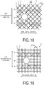
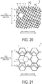
- FIGS. 18 to 21 are explanatory diagrams illustrated modified examples of the pneumatic tire illustrated in FIG. 4 . These drawings illustrate the positional relationship between the sipes 6, the narrow shallow grooves 7, and the recessed portion 8.
- the present invention is not limited to such a configuration, and as illustrated in FIGS. 18 to 21 , the narrow shallow grooves 7 may be disposed intersecting each other or communicating with each other.
- the plurality of narrow shallow grooves 7 are disposed in a mesh-like manner.
- the narrow shallow grooves 7 may be disposed at an incline with respect to the tire circumferential direction and the tire lateral direction (see FIG. 18 ) or disposed in parallel with the tire circumferential direction and the tire lateral direction (see FIG. 19 ).
- at least one of the narrow shallow grooves 7, for example may be disposed in an arc-like or wave-like curving manner (see FIG. 20 ).
- the narrow shallow grooves 7 may have an annular structure and be disposed communicating with each other ( FIG. 21 ).
- the narrow shallow grooves 7 are disposed in a honeycomb-like manner.
- the recessed portion 8 is disposed intersecting two or more narrow shallow grooves 7 that do not intersect each other.
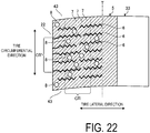
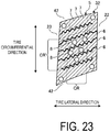
- FIGS. 22 to 24 are explanatory diagrams illustrating a modified example of the pneumatic tire illustrated in FIG. 2 .
- FIG. 22 is a plan view of one block 5 that composes the shoulder land portion 33.
- FIG. 23 is a plan view of one block 5 that composes the second land portion 32.
- FIG. 24 is a plan view of one block 5 that composes the center land portion 31.
- the plurality of recessed portions 8 are disposed unevenly in the continuous contact patch of one block 5 so that, as defined above for the continuous contact patch, the opening area ratio Sc of the recessed portions 8 in the central portion region CR in the tire lateral direction is greater than the opening area ratio Se of the recessed portions 8 in the end portion regions in the tire lateral direction (Se ⁇ Sc).
- all of the blocks 5 of the land portions 31 to 33 have the relationship Ne ⁇ Nc, wherein Nc is the disposal number of recessed portions 8 in the central portion region CR in the tire lateral direction and Ne is the disposal number of recessed portions 8 in the end portion regions in the tire lateral direction.
- the opening area ratio Sc' of the recessed portions 8 in the central portion region CR' in the tire circumferential direction defined at the continuous contact patch and the opening area ratio Se' of the recessed portions 8 in the end portion regions in the tire circumferential direction have the relationship Se' ⁇ Sc'.
- the opening area ratio Sc'/Se' of the recessed portions 8 preferably have the relationship 1.50 ⁇ Sc'/Se, and more preferably have the relationship 3.00 ⁇ Sc'/Se'.
- the maximum value of the ratio Sc'/Se' is not particularly limited but is constrained by its relationship with the disposal density and the like of the recessed portions 8 and the opening area. In a configuration in which all of the recessed portions 8 are disposed in the central portion region CR, Se' is equal to zero, thus satisfying the condition Se' ⁇ Sc'.
- the central portion region CR' in the tire circumferential direction is defined as the region in the central portion occupying 50% of the continuous contact patch in the tire circumferential direction (see FIG. 22 ).
- the end portion region in the tire circumferential direction is defined as the region of the front and back end portions each occupying 25% of the continuous contact patch in the tire circumferential direction.
- the central portion region and the end portion regions are defined excluding notched portions partially formed in the land portions 31 to 33.
- the contact patch of each block 5 that composes the row of blocks is divided into a central portion region and end portion regions. Note that the dashed lines of FIG. 22 indicate the boundary lines between the central portion region and the end portion regions.
- the disposal number Nc' of recessed portions 8 in the central portion region CR' in the tire circumferential direction in one block 5 and the disposal number Ne' of the recessed portions 8 in the end portion regions in the tire circumferential direction having the relationship Ne' ⁇ Nc' the condition Se' ⁇ Sc' for the opening area ratio of the recessed portions 8 is satisfied.
- the disposal numbers Nc', Ne' of the recessed portions 8 preferably have the relationship 1.50 ⁇ c'/Ne', and more preferably the relationship 3.00 ⁇ Nc'/Ne'.
- the maximum value of the ratio Nc'/Ne' is not particularly limited but is constrained by its relationship with the disposal density of the recessed portions 8. In a configuration in which all of the recessed portions 8 are disposed in the central portion region CR', Ne' is equal to zero, thus satisfying the conditions Ne' ⁇ Nc' and Se' ⁇ Sc'.
- 70% or more, and preferably 80% or more of the blocks 5 that compose one row of blocks preferably satisfy the conditions Ne' ⁇ Nc' and Se' ⁇ Sc' for the recessed portions 8 described above. In the entire tread, it is only required that at least one land portion satisfy the conditions for the row of blocks.
- the recessed portions 8 are disposed densely in the central portion region CR of the blocks 5 which are subject to lower ground contact pressure.
- the contact patch area of the central portion region CR is decreased, the ground contact pressure is increased, and the snow column shear force (digging out force) provided by the recessed portions 8 is increased.
- the traction performance of the tire is improved and the performance on snow of the tire is improved.
- the recessed portions 8 sparsely in the end portion regions, the contact patch area of the end portion regions of the block 5 is ensured. As a result, the adhering function in the end portion regions is ensured, and performance on ice of the tire is ensured.
- one block 5 of the shoulder land portion 33 includes a total of eleven recessed portions 8 in the contact patch, seven recessed portions 8 in the central portion region CR' in the tire circumferential direction and a total of four recessed portions 8 in the front and back end portion regions (reference sign is omitted in the drawings) in the tire circumferential direction.
- the recessed portions 8 have the same opening shape and the same opening area.
- all of the recessed portions 8 of the blocks 5 satisfy the condition Nc' ⁇ Ne' described above.
- the shoulder land portions 33 have a great effect on the braking performance of the tire.
- the recessed portions 8 being densely disposed in the central portion region CR' in the tire lateral direction of the block 5 of the shoulder land portion 33, the function of the recessed portions 8 to improve braking performance on snow is significantly obtained.
- one block 5 of the second land portion 32 located outward in the tire lateral direction includes a total of nine recessed portions 8 in the contact patch, five recessed portions 8 in the central portion region CR' in the tire circumferential direction and four recessed portions 8 in the front and back end portion regions (reference sign is omitted in the drawings) in the tire circumferential direction. Additionally, the recessed portions 8 have the same opening shape and the same opening area.
- the second land portions 32 (defined as the laterally inner land portions defined by the outermost circumferential main groove 22) have a great effect on driving/braking performance of the tire.
- the blocks 5 of the second land portion 32 being provided with the recessed portions 8 sparsely in the end portion regions in the tire lateral direction, the contact patch area of the end portion regions of the block 5 in the tire lateral direction is ensured.
- the adhering function in the end portion regions is ensured, and performance on ice of the tire is ensured.
- one block 5 of the center land portion 31 includes a total of 19 recessed portions 8 in the contact patch, eleven recessed portions 8 in the central portion region CR' in the tire circumferential direction and eight recessed portions 8 in the front and back end portion regions (reference sign is omitted in the drawings) in the tire circumferential direction. Additionally, the recessed portions 8 have the same opening shape and the same opening area.
- the center land portion 31 has a great effect on the driving performance of the tire.
- the recessed portions 8 being disposed densely in the central portion regions CR' of the blocks 5 of the center land portion 31 in the tire circumferential direction, the contact patch area of the central portion region CR' is decreased, the ground contact pressure is increased, and the snow column shear force provided via the recessed portions 8 is increased.
- the traction performance of the tire is improved and the effect of the recessed portions 8 to improve driving performance of the tire is significantly obtained.
- FIGS. 25 to 28 are explanatory diagrams illustrating a modified example of the pneumatic tire illustrated in FIG. 2 .
- FIG. 25 is a plan view of the tread surface of the pneumatic tire 1.
- FIG. 26 is a plan view of one block 5 that composes the shoulder land portion 33.
- FIG. 27 is a plan view of one block 5 that composes the second land portion 32.
- FIG. 28 is a plan view of one block 5 that composes the center land portion 31.
- the opening area ratio Sc of the recessed portions 8 in the central portion region CR of one block 5 in the tire lateral direction is made greater than the opening area ratio Se of the recessed portions 8 in the end portion regions (reference sign is omitted in the drawings) in the tire lateral direction (Se ⁇ Sc).
- the recessed portions 8 are densely disposed in the central portion region CR of the block 5 in the tire lateral direction.
- the recessed portions 8 of the land portions 31 to 33 have the same opening shape and the same opening area.
- the present invention is not limited to such a configuration, and by the plurality of recessed portions 8 having different opening areas in the contact patch of one rib or block, the opening area ratio Sc of the recessed portions 8 in the central portion region of one rib or block in the tire lateral direction may be made greater than the opening area ratio Se of the recessed portions 8 in the end portion regions in the tire lateral direction (Se ⁇ Sc). In other words, the recessed portions 8 with a relatively large opening area are disposed in the central portion region CR in the tire lateral direction.
- the average value Ac of the opening area of the recessed portions 8 in the central portion region CR in the tire lateral direction and the average value Ae of the opening area of the recessed portions 8 in the end portion regions (reference sign is omitted in the drawings) in the tire lateral direction having the relationship Ae ⁇ Ac the condition Se ⁇ Sc for the opening area of the recessed portions 8 is satisfied.
- the average values Ac, Ae of the opening area of the recessed portions 8 preferably have the relationship 1.5 ⁇ Ac/Ae ⁇ 4.0, and more preferably the relationship 2.0 ⁇ Ac/Ae ⁇ 3.0. In a configuration in which all of the recessed portions 8 are disposed in the central portion region CR, Ae is equal to zero, thus satisfying the conditions Ae ⁇ Ac and Se ⁇ Sc.
- the average values Ac, Ae of the opening area are each calculated as the ratio between the sum of the opening area of the recessed portions in a predetermined region and the total number of recessed portions in the predetermined region.
- 70% or more, and preferably 80% or more of the blocks 5 that compose one row of blocks preferably satisfy the conditions Ac ⁇ Ae and Sc ⁇ Se for the opening area of the recessed portions 8 described above. In the entire tread, it is only required that at least one land portion satisfy the conditions Ac ⁇ Ae and Sc ⁇ Se for the opening area of the recessed portions 8 described above.
- the recessed portions 8 with a relatively large opening area are disposed in the central portion regions CR of the blocks 5 which are subject to low ground contact pressure.
- the contact patch area of the central portion region CR is decreased, the ground contact pressure is increased, and the snow column shear force (digging out force) provided by the recessed portions 8 is increased.
- the traction performance of the tire is improved and the performance on snow of the tire is improved.
- the recessed portions 8 with a relatively small opening area in the end portion regions the contact patch area of the end portion regions of the block 5 is ensured. As a result, the adhering function in the end portion regions is ensured, and performance on ice of the tire is ensured.
- one block 5 of the shoulder land portion 33 includes a total of 16 recessed portions 8 in the contact patch, eight recessed portions 8 in both the central portion region CR and the end portion regions (reference sign is omitted in the drawings) in the tire lateral direction.
- the recessed portions 8 have the same opening shape. Additionally, the recessed portions 8 with a relatively large opening area are disposed in the central portion region CR, and the recessed portions 8 with a relatively small opening area are disposed in the end portion regions.
- the condition Ae ⁇ Ac for the opening area of the recessed portions 8 and the condition Se ⁇ Sc for the opening area ratio are both satisfied in each region.
- the recessed portions 8 in all of the blocks 5 satisfy the conditions Ae ⁇ Ac and Se ⁇ Sc described above (see FIG. 25 ).
- one block 5 of the second land portion 32 located outward in the tire lateral direction includes a total of 16 recessed portions 8 in the contact patch, eight recessed portions 8 in both the central portion region CR and the left and right end portion regions (reference sign is omitted in the drawings) in the tire lateral direction.
- the recessed portions 8 have the same opening shape. Additionally, the recessed portions 8 with a relatively large opening area are disposed in the central portion region CR, and the recessed portions 8 with a relatively small opening area are disposed in the end portion regions.
- the condition Ae ⁇ Ac for the opening area of the recessed portions 8 and the condition Se ⁇ Sc for the opening area ratio are both satisfied in each region.
- the recessed portions 8 in all of the blocks 5 satisfy the conditions Ae ⁇ Ac and Se ⁇ Sc described above (see FIG. 25 ).
- one block 5 of the center land portion 31 includes a total of 35 recessed portions 8 in the contact patch, 17 recessed portions 8 in the central portion region CR' in the tire lateral direction and a total of 18 recessed portions 8 in the end portion regions (reference sign is omitted in the drawings) in the tire lateral direction.
- the recessed portions 8 have the same opening shape. Additionally, the recessed portions 8 with a relatively large opening area are disposed in the central portion region CR, and the recessed portions 8 with a relatively small opening area are disposed in the end portion regions. Additionally, the condition Ae ⁇ Ac for the opening area of the recessed portions 8 and the condition Se ⁇ Sc for the opening area ratio are both satisfied in each region. Additionally, in the center land portion 31, the recessed portions 8 in all of the blocks 5 satisfy the conditions Ae ⁇ Ac and Se ⁇ Sc described above (see FIG. 25 ).
- 70% or more, and preferably 80% or more of the recessed portions 8 disposed in the central portion region CR in the tire lateral direction preferably have an opening area larger than the average value of the opening area of the recessed portions 8 disposed in the block 5.
- the majority of the larger recessed portions 8 are disposed in the central portion region CR.
- one block 5 is provided with two types of recessed portions 8 with differing opening areas, and all of the recessed portions 8 with the larger opening area are disposed in the central portion region CR.
- recessed portions 8 are disposed in the central portion region CR, and only the smaller recessed portions 8 are disposed in the end portion regions. As a result, the regions are provided with recessed portions 8 of different sizes. As a result, a distinctive arrangement pattern of the recessed portions 8 is formed.
- the present invention is not limited to such a configuration and at least one of the smaller recessed portions may be disposed in the central portion region CR (not illustrated).
- the recessed portions 8 with an opening area less than the average value are preferably disposed on the outermost side of the continuous contact patch in the tire lateral direction.
- the contact patch area of the blocks 5 in the end portion regions is ensured, and the adhering function in the end portion regions with respect to icy road surfaces is ensured.
- the performance on ice of the tire is ensured.
- the smaller recessed portions 8 are disposed along the edges of the block 5 proximal to the circumferential grooves 21 to 23. As a result, the contact patch area of the end portion regions is ensured.
- the land portions 31 to 33 are rows of blocks that each include a plurality of blocks 5, and include a plurality of sipes 6 and a plurality types of recessed portions 8 with differing opening areas.
- the plurality of sipes 6 are disposed side by side in the tire circumferential direction to divide each of the land portions 31 to 33 into a plurality of sections.
- the recessed portions 8 with an opening area larger than the average value are preferably disposed in at least one of three sections adjacent in the tire circumferential direction.
- three discretionary adjacent sections defined by the sipes 6 include at least one larger recessed portion 8.
- the larger recessed portions 8 being disposed in the central portion region CR dispersed in the tire circumferential direction, during travel on snowy road surfaces, the function of improving the snow column shear force provided by the recessed portions 8 is efficiently obtained.
- all of the sections defined by the sipes 6 include a larger recessed portion 8.
- the recessed portions 8 are disposed dispersedly throughout the sections of the central portion region CR.
- the land portions 31 to 33 are rows of blocks that each include a plurality of blocks 5, and the recessed portions 8 with an opening area less than the average value are preferably disposed in the corner portions of the blocks 5.
- the contact patch area of the corner portions is ensured, and the adhering function of the corner portions with respect to icy road surfaces is ensured.
- the performance on ice of the tire is ensured.
- the smaller recessed portions 8 are disposed at all of the corner portions of the blocks 5, the corner portions being formed where the circumferential grooves 21 to 23 and the lug grooves 41 to 43 meet (see FIG. 25 ).
- the smaller recessed portions 8 are also disposed in the corner portions of the notched portions 311 formed in the center land portion 33 (see FIG. 28 ). As a result, the contact patch area of the corner portions is ensured.
- the disposal number Nc of recessed portions 8 in the central portion region CR of each block 5 and the disposal number Ne of the recessed portions 8 in the end portion regions are substantially the same, and the disposal densities of the recessed portions 8 in the regions are substantially equal to each other. Additionally, the disposal numbers Nc, Ne of the recessed portions 8 in each region preferably have the relationship 0.90 ⁇ Nc/Ne ⁇ 1.10. As a result, the recessed portions 8 are disposed in the blocks 5 with a uniform disposal density.
- the present invention is not limited to such a configuration, and in addition to the condition Ae ⁇ Ac described above, the disposal numbers Nc, Ne of the recessed portions 8 in each region may have the relationship 1.20 ⁇ Nc/Ne, and more preferably the relationship 1.50 ⁇ Nc/Ne.
- the recessed portions 8 in the central portion region CR in the tire lateral direction, the recessed portions 8 have a relatively large opening area and are disposed densely. As a result, the ratio Ac/Ae of the opening area of the recessed portions 8 in each region can be reduced while the condition Se ⁇ Sc for the opening area ratio of the recessed portions 8 in each region can be efficiently adjusted.
- FIGS. 29 to 31 are explanatory diagrams illustrating a modified example of the pneumatic tire illustrated in FIG. 25 .
- FIG. 29 is a plan view of one block 5 that composes the shoulder land portion 33.
- FIG. 30 is a plan view of one block 5 that composes the second land portion 32.
- FIG. 31 is a plan view of one block 5 that composes the center land portion 31.
- the plurality of recessed portions 8 are given different opening areas in the contact patch of one rib or block so that the opening area ratio Sc of the recessed portions 8 in the central portion region in the tire lateral direction of one rib or block is greater than the opening area ratio Se of the recessed portions 8 in the end portion regions in the tire lateral direction (Se ⁇ Sc).
- the present invention is not limited to such a configuration, and the plurality of recessed portions 8 may be given different opening areas in the contact patch of one rib or block so that the opening area ratio Sc' of the recessed portions 8 in the central portion region CR' in the tire circumferential direction of one rib or block is greater than the opening area ratio Se' of the recessed portions 8 in the end portion regions in the tire circumferential direction (Se' ⁇ Sc').
- the recessed portions 8 with a relatively large opening area are disposed in the central portion region CR' in the tire circumferential direction.
- the average value Ac' of the opening area of the recessed portions 8 in the central portion region CR' in the tire circumferential direction and the average value Ae' of the opening area of the recessed portions 8 in the end portion regions (reference sign is omitted in the drawings) in the tire circumferential direction having the relationship Ae' ⁇ Ac' the condition Se' ⁇ Sc' for the opening area of the recessed portions 8 is satisfied.
- the average values Ac', Ae' of the opening area of the recessed portions 8 preferably have the relationship 1.5 ⁇ Ac'/Ae' ⁇ 4.0, and more preferably the relationship 2.0 ⁇ Ac'/Ae' ⁇ 3.0. In a configuration in which all of the recessed portions 8 are disposed in the central portion region CR', Ae' is equal to zero, thus satisfying the conditions Ae' ⁇ Ac' and Se' ⁇ Sc'.
- 70% or more, and preferably 80% or more of the blocks 5 that compose one row of blocks preferably satisfy the conditions Ae' ⁇ Ac' and Se' ⁇ Sc' for the opening area of the recessed portions 8 described above. In the entire tread, it is only required that at least one land portion satisfy the conditions for the row of blocks.
- the recessed portions 8 with a relatively large opening area are disposed in the central portion regions CR of the blocks 5 which are subject to low ground contact pressure.
- the contact patch area of the central portion region CR is decreased, the ground contact pressure is increased, and the snow column shear force (digging out force) provided by the recessed portions 8 is increased.
- the traction performance of the tire is improved and the performance on snow of the tire is improved.
- the recessed portions 8 with a relatively small opening area in the end portion regions the contact patch area of the end portion regions of the block 5 is ensured. As a result, the adhering function in the end portion regions is ensured, and performance on ice of the tire is ensured.
- one block 5 of the shoulder land portion 33 includes a total of 16 recessed portions 8 in the contact patch, eight recessed portions 8 in both the central portion region CR' and the end portion regions (reference sign is omitted in the drawings) in the tire circumferential direction.
- the recessed portions 8 have the same opening shape. Additionally, the recessed portions 8 with a relatively large opening area are disposed in the central portion region CR', and the recessed portions 8 with a relatively small opening area are disposed in the end portion regions.
- the condition Ae' ⁇ Ac' for the opening area of the recessed portions 8 and the condition Se' ⁇ Sc' for the opening area ratio are both satisfied in each region.
- the recessed portions 8 in all of the blocks 5 satisfy the conditions Ae' ⁇ Ac' and Se' ⁇ Sc' described above.
- one block 5 of the second land portion 32 located outward in the tire circumferential direction includes a total of 16 recessed portions 8 in the contact patch, eight recessed portions 8 in both the central portion region CR' and the left and right end portion regions (reference sign is omitted in the drawings) in the tire circumferential direction.
- the recessed portions 8 have the same opening shape. Additionally, the recessed portions 8 with a relatively large opening area are disposed in the central portion region CR', and the recessed portions 8 with a relatively small opening area are disposed in the end portion regions.
- condition Ae' ⁇ Ac' for the opening area of the recessed portions 8 and the condition Se' ⁇ Sc' for the opening area ratio are both satisfied in each region.
- the recessed portions 8 in all of the blocks 5 satisfy the conditions Ae' ⁇ Ac' and Se' ⁇ Sc' described above.
- one block 5 of the center land portion 31 includes a total of 36 recessed portions 8 in the contact patch, 18 recessed portions 8 in both the central portion region CR' and the left and right end portion regions (reference sign is omitted in the drawings) in the tire circumferential direction.
- the recessed portions 8 have the same opening shape. Additionally, the recessed portions 8 with a relatively large opening area are disposed in the central portion region CR', and the recessed portions 8 with a relatively small opening area are disposed in the end portion regions.
- the condition Ae' ⁇ Ac' for the opening area of the recessed portions 8 and the condition Se' ⁇ Sc' for the opening area ratio are both satisfied in each region. Additionally, in the entire center land portion 31, the recessed portions 8 in all of the blocks 5 satisfy the conditions Ae' ⁇ Ac' and Se' ⁇ Sc' described above.
- 70% or more, and preferably 80% or more of the recessed portions 8 disposed in the central portion region CR' in the tire circumferential direction preferably have an opening area larger than the average value.
- the majority of the larger recessed portions 8 are disposed in the central portion region CR'.
- one block 5 is provided with two types of recessed portions 8 with differing opening areas, and all of the recessed portions 8 with the larger opening area are disposed in the central portion region CR'.
- recessed portions 8 are disposed in the central portion region CR', and only the smaller recessed portions 8 are disposed in the end portion regions. As a result, the regions are provided with recessed portions 8 of different sizes. As a result, a distinctive arrangement pattern of the recessed portions 8 is formed.
- the present invention is not limited to such a configuration and at least one of the smaller recessed portions may be disposed in the central portion region CR'.
- the recessed portions 8 with an opening area less than the average value are preferably disposed on the outermost side of the continuous contact patch in the tire circumferential direction.
- the contact patch area of the blocks 5 in the end portion regions is ensured, and the adhering function of the end portion regions is ensured.
- the smaller recessed portions 8 are disposed along the edges of the block 5 proximal to the lug grooves 41, 42. As a result, the contact patch area of the end portion regions is ensured.
- the land portions 31 to 33 are rows of blocks that each include a plurality of blocks 5, and the recessed portions 8 with an opening area less than the average value are preferably disposed in the corner portions of the blocks 5.
- the contact patch area of the corner portions is ensured, and the adhering function of the corner portions is ensured.
- the performance on ice of the tire is ensured.
- the smaller recessed portions 8 are disposed in the blocks 5 at all of the corner portions formed where the circumferential grooves 21 to 23 and the lug grooves 41 to 43 meet (see FIG. 25 ). As a result, the contact patch area of the corner portions is ensured.
- the disposal number Nc' of recessed portions 8 in the central portion region CR' of each block 5 and the disposal number Ne' of the recessed portions 8 in the end portion regions are substantially the same, and the disposal densities of the recessed portions 8 in the regions are substantially equal to each other. Additionally, the disposal numbers Nc', Ne' of the recessed portions 8 in each region preferably have the relationship 0.90 ⁇ Nc'/Ne' ⁇ 1.10. As a result, the recessed portions 8 are disposed in the blocks 5 with a uniform disposal density.
- the present invention is not limited to such a configuration, and in addition to the condition Ae' ⁇ Ac' described above, the disposal numbers Nc', Ne' of the recessed portions 8 in each region may have the relationship 1.20 ⁇ Nc'/Ne', and more preferably the relationship 1.50 ⁇ Nc'/Ne'.
- the recessed portions 8 in the central portion region CR' in the tire circumferential direction, the recessed portions 8 have a relatively large opening area and are disposed densely. As a result, the ratio Ac'/Ae' of the opening area of the recessed portions 8 in each region can be reduced while the condition Se' ⁇ Sc' for the opening area ratio of the recessed portions 8 in each region can be efficiently adjusted.
- the pneumatic tire 1 is provided with, in the tread surface, the land portions 31 to 33 that include a rib or a plurality of blocks (see FIGS. 2 , 25 ).
- the land portions 31 to 33 are provided with the plurality of narrow shallow grooves 7 and the plurality of recessed portions 8 in the contact patch (see FIGS. 3 and 4 ).
- the opening area ratio Sc of the recessed portions 8 in the central portion region CR in the tire lateral direction of one continuous contact patch and the opening area ratio Se of the recessed portions 8 in the end portion regions in the tire lateral direction have the relationship Se ⁇ Sc, where the central portion region is defined as the region in the central portion in the tire lateral direction occupying 50% of the continuous contact patch of the land portions 31 to 33, and the end portion regions are defined as the regions in the left and right end portions in the tire lateral direction occupying 25%.
- Such a configuration is advantageous because: (1) by the land portions 31 to 33 being provided with recessed portions 8 in the contact patch, the edge components of the land portions 31 to 33 are increased and the braking performance on ice of the tire is improved; and (2) by the opening area ratio of the recessed portions 8 being greater in the central portion region CR in the tire lateral direction, the contact patch area of the central portion region CR is reduced, the ground contact pressure is increased, and the snow column shear force (digging out force) provided by the recessed portions 8 is increased. As a result, the traction performance of the tire is improved and the performance on snow of the tire is improved.
- the opening area ratio of the recessed portions 8 being smaller in the end portion regions in the tire lateral direction, the contact patch area of the end portion regions of the block 5 is ensured.
- the adhering function in the end portion regions with respect to an icy road surface is ensured, and performance on ice of the tire is ensured.
- the recessed portion 8 being shallow compared to the sipes (for example a linear sipe 6 or a circular sipe (not illustrated)) the rigidity of the land portions 31 to 33 is appropriate ensured.
- the braking performance on ice of the tire is ensured.
- the opening area ratio Sc of the recessed portions 8 in the central portion region CR in the tire lateral direction and the opening area ratio Se of the recessed portions 8 in the end portion regions in the tire lateral direction have the relationship 1.50 ⁇ Sc/Se.
- the ratio Sc/Se of the opening area ratios of the recessed portions 8 in each region is ensured, and the function provided by the non-uniform opening area of the recessed portions 8 is appropriately obtained.
- the disposal number Nc of the recessed portions 8 in the central portion region CR in the tire lateral direction and the disposal number Ne of the recessed portions 8 in the end portion regions in the tire lateral direction have the relationship Ne ⁇ Nc (see FIGS. 3 , 6 , and 7 ).
- the contact patch area of the central portion region CR is reduced, the ground contact pressure is increased, and the snow column shear force (digging out force) provided by the recessed portions 8 is increased.
- the traction performance of the tire is improved and the performance on snow of the tire is improved.
- the recessed portions 8 sparsely in the end portion regions, the contact patch area of the end portion regions of the block 5 is ensured. As a result, the adhering function in the end portion regions with respect to an icy road surface is ensured, and performance on ice of the tire is ensured.
- the disposal number Nc of the recessed portions 8 in the central portion region CR in the tire lateral direction and the disposal number Ne of the recessed portions 8 in the end portion regions in the tire lateral direction have the relationship 1.50 ⁇ Nc/Ne (see FIGS. 3 , 6 , and 7 ).
- Such a configuration is advantageous because the density of the recessed portions 8 in each region is made appropriate, and the function of improving the performance on snow of the tire is appropriately obtained.
- the disposal density Da of the recessed portions 8 in the entire region of one continuous contact patch is in the range 0.8 unit/cm 2 ⁇ Da ⁇ 4.0 unit/cm 2 .
- Such a configuration is advantageous because the disposal density of the recessed portions 8 is made appropriate.
- the disposal number of recessed portions 8 is ensured, and the film of water removing function of the recessed portion 8 is appropriately ensured.
- Da ⁇ 4.0 unit/cm 2 the contact patch area of the land portions 31 to 33 is appropriately ensured.
- the land portions 31 to 33 include, in the contact patch, the plurality of sipes 6, and the recessed portions 8 are disposed spaced apart from the sipes 6 (for example, see FIG. 3 ).
- Such a configuration is advantageous because by disposing the recessed portions 8 and the sipes 6 separate from each other, the braking performance on ice and the performance on snow of the tire is improved.
- the sipes 6 are disposed side by side in the tire circumferential direction to divide each of the land portions 31 to 33 into a plurality of sections. Additionally, at least one of two discretionary adjacent sections includes a recessed portion 8 in the central portion region CR in the tire lateral direction (see FIGS. 3 and 7 ). Such a configuration is advantageous because by disposed the recessed portions 8 densely in the central portion region CR in the tire lateral direction, the drainage properties of the central portion region CR, which has poor drainage, is improved.
- the sipes 6 are disposed side by side in the tire circumferential direction to divide each of the land portions 31 to 33 into a plurality of sections.
- Three adjacent sections include a section including a recessed portion 8 in the central portion region CR in the tire lateral direction and a section including a recessed portion 8 in the end portion regions in the tire lateral direction (for example, see FIGS. 3 and 6 ).
- Such a configuration is advantageous because the recessed portions 8 are disposed dispersedly throughout the central portion regions CR and the end portion regions of the land portions 31 to 33.
- the sipes 6 are disposed side by side in the tire circumferential direction to divide each of the land portions 31 to 33 into a plurality of sections.
- Three discretionary sections adjacent in the tire circumferential direction include a section including a recessed portion 8 and a section without a recessed portion 8 (see FIG. 7 ).
- the recessed portions 8 are disposed in a dispersed manner.
- Such a configuration is advantageous because the contact patch area of the land portions 31 to 33 is ensured, and the braking performance on ice and the performance on snow of the tire are improved.
- the land portions 31 to 33 are rows of blocks that each include a plurality of blocks 5, and the recessed portions 8 are disposed in the corner portions of the blocks 5 (see FIGS. 3 , 6 , and 7 ).
- the recessed portions 8 are disposed in the corner portions of the blocks 5 where the ground contact pressure is high and a film of water is likely to form.
- Such a configuration is advantageous because on icy road surfaces, a film of water on the road contact surface is efficiently absorbed and the braking performance on ice of the tire is improved.
- the ground contact pressure at the corner portions is further increased due to the recessed portions 8, increasing the snow column shear force and thus improving the performance on snow of the tire.
- the land portions 31 to 33 are rows of blocks that each include a plurality of blocks 5, and the recessed portions 8 are not disposed in the end portions of blocks 5 in the tire circumferential direction or the central portion region CR in the tire lateral direction (see FIGS. 3 , 6 , and 7 ).
- Such a configuration is advantageous because the contact patch area and the rigidity of the end portions of the blocks on the leading side and trailing side is ensured, and the braking performance on ice and the performance on snow of the tire are improved.
- the opening area of the recessed portion 8 ranges from 2.5 mm 2 to 10 mm 2 .
- Such a configuration is advantageous because the opening area of the recessed portions 8 is made appropriate. In other words, by the opening area of the recessed portions 8 being 2.5 mm2 or greater, the edge function and the water absorbency of the recessed portions 8 are ensured. Additionally, by the opening area of the recessed portions 8 being 10 mm2 or less, the contact patch area and the rigidity of the land portions 31 to 33 are ensured.
- the recessed portions 8 have a circular (see FIG. 4 ) or elliptical shape (not illustrated) in the contact patch of the land portions 31 to 33.
- Such a configuration is advantageous because compared to a configuration (not illustrated) in which the recessed portions 8 have a polygonal shape, uneven wear of the contact patch of the land portions 31 to 33 can be suppressed.
- the wall angle a of the recessed portions 8 is in the range -85 degrees ⁇ a ⁇ 95 degrees (see FIG. 5 ). Such a configuration is advantageous because the edge function of the recessed portions 8 is improved.
- the depth Hd of the recessed portions 8 and the groove depth Hg of the narrow shallow grooves 7 have the relationship 0.5 ⁇ Hd/Hg ⁇ 1.5 (see FIG. 5 ).
- Such a configuration is advantageous because the depth Hd of the recessed portions 8 is made appropriate. In other words, by satisfying 0.5 ⁇ Hd/Hg, the water absorbing function of the recessed portions 8 is ensured. Additionally, by satisfying Hd/Hg ⁇ 1.5, a decrease in rigidity of the land portions 31 to 33 caused by the recessed portions 8 being too deep relative to the narrow shallow grooves 7 can be suppressed.
- At least one recessed portion 8 is disposed in a position that corresponds to a vent hole of a tire mold (not illustrated).
- a vent hole is effectively utilized, and the number of unnecessary recesses are reduced in the contact patch of the land portions 31 to 33, allowing the contact patch area of the land portions 31 to 33 to be appropriately ensured.
- the average value Ac of the opening area of the recessed portions 8 in the central portion region CR in the tire lateral direction and the average value Ae of the opening area of the recessed portions 8 in the end portion regions in the tire lateral direction have the relationship Ae ⁇ Ac (see FIGS. 25 to 28 ).
- the contact patch area of the central portion region CR is reduced, the ground contact pressure is increased, and the snow column shear force (digging out force) provided by the recessed portions 8 is increased.
- the traction performance of the tire is improved and the performance on snow of the tire is improved.
- the recessed portions 8 with a relatively small opening area in the end portion regions, the contact patch area of the end portion regions of the block 5 is ensured.
- the adhering function of the blocks 5 with respect to an icy road surface is ensured, and performance on ice of the tire is ensured.
- the average value Ac of the opening area of the recessed portions 8 in the central portion region CR in the tire lateral direction and the average value Ae of the opening area of the recessed portions 8 in the end portion regions in the tire lateral direction have the relationship 1.5 ⁇ Ac/Ae ⁇ 4.0.
- Such a configuration is advantageous because the ratio Ac/Ae of the opening area of the recessed portions 8 in each region is made appropriate.
- 1.5 ⁇ Ac/Ae the ratio Ac/Ae of the opening area of the recessed portions 8 in each region is ensured, and the function of the recessed portions 8 to improve the performance on snow of the tire is appropriately obtained.
- Ac/Ae ⁇ 4.0 the ratio Ae/Ac of the opening area is kept from being excessive, and uneven wear of the blocks 5 is suppressed.
- the land portions 31 to 33 include a plurality of types of recessed portions 8 with differing opening areas, and 70% or more of the recessed portions 8 disposed in the central portion region CR in tire lateral direction have an opening area larger than the average value of the opening area of the recessed portions 8 disposed in the continuous contact patch (see FIGS. 26 to 28 ).
- Such a configuration is advantageous because the function of increasing the snow column shear force provided by the recessed portions 8 is appropriately ensured, and the performance on snow of the tire is improved.
- the land portions 31 to 33 include a plurality of types of recessed portions 8 with differing opening areas, and the recessed portions 8 with a smaller opening area than the average value of the opening area of the recessed portions 8 disposed in the continuous contact patch are disposed on the outermost side of the continuous contact patch in the tire lateral direction (see FIGS. 26 to 28 ).
- Such a configuration is advantageous because the contact patch area of the end portion regions of the blocks 5 is ensured, and the performance on ice of the tire is ensured.
- the land portions 31 to 33 include a plurality of sipes 6 and a plurality of types of recessed portion 8 with differing opening areas.
- the plurality of sipes 6 are disposed side by side in the tire circumferential direction and divide each of the land portions 31 to 33 into a plurality of sections (see FIGS. 26 to 28 ).
- the recessed portions 8 with an opening area larger than the average value of the opening area of the recessed portions 8 disposed in the continuous contact patch are disposed in at least one of three discretionary sections adjacent in the tire circumferential direction.
- Such a configuration is advantageous because by disposing the larger recessed portions 8 dispersed in the tire circumferential direction, the function of increasing the snow column shear force provided by the recessed portions 8 is appropriately ensured.
- the land portions 31 to 33 are rows of blocks that each include a plurality of blocks 5 and a plurality of types of recessed portion 8 with differing opening areas (see FIGS. 26 to 28 ).
- the recessed portions 8 with an opening area smaller than the average value of the opening area of the recessed portions 8 disposed in the continuous contact patch are disposed in the corner portions of the blocks 5.
- the pneumatic tire 1 is provided with, in the tread surface, the land portions 31 to 33 that include a plurality of blocks 5 (see FIG. 2 ).
- the land portions 31 to 33 are provided with the plurality of narrow shallow grooves 7 and the plurality of recessed portions 8 in the contact patch (see FIG. 4 ).
- the opening area ratio Sc' of the recessed portions 8 in the central portion region CR' in the tire circumferential direction of one continuous contact patch and the opening area ratio Se' of the recessed portions 8 in the end portion regions in the tire circumferential direction have the relationship Se' ⁇ Sc', where the central portion region is defined as the region in the central portion in the tire circumferential direction occupying 50% of the continuous contact patch, and the end portion regions are defined as the regions in the front and back end portions in the tire circumferential direction occupying 25% (see FIGS. 22 to 24 ).
- Such a configuration is advantageous because: (1) by the land portions 31 to 33 being provided with recessed portions 8 in the contact patch, the edge components of the land portions 31 to 33 are increased and the braking performance on ice of the tire is improved; and (2) by the opening area ratio of the recessed portions 8 being greater in the central portion region CR in the tire circumferential direction, the contact patch area of the central portion region CR is reduced, the ground contact pressure is increased, and the snow column shear force (digging out force) provided by the recessed portions 8 is increased. As a result, the traction performance of the tire is improved and the performance on snow of the tire is improved.
- the opening area ratio of the recessed portions 8 being smaller in the central portion region CR in the tire circumferential direction, the contact patch area of the central portion region of the land portions 31 to 33 is ensured, and the braking performance on ice of the tire is improved.
- the recessed portion 8 being shallow compared to the sipes (for example a linear sipe 6 or a circular sipe (not illustrated)) the rigidity of the land portions 31 to 33 is appropriate ensured.
- the disposal number Nc' of the recessed portions 8 in the central portion region CR' in the tire circumferential direction and the disposal number Ne' of the recessed portions 8 in the end portion regions in the tire circumferential direction have the relationship Ne' ⁇ Nc' (see FIGS. 22 to 24 ).
- the recessed portions 8 being densely disposed in the central portion region CR' in the tire circumferential direction, the contact patch area of the central portion region CR' is reduced, the ground contact pressure is increased, and the snow column shear force (digging out force) provided by the recessed portions 8 is increased.
- the traction performance of the tire is improved and the performance on snow of the tire is improved.
- the recessed portions 8 sparsely in the end portion regions, the contact patch area of the end portion regions of the block 5 is ensured. As a result, the adhering function in the end portion regions with respect to an icy road surface is ensured, and performance on ice of the tire is ensured.
- the average value Ac' of the opening area of the recessed portions 8 in the central portion region CR' in the tire circumferential direction and the average value Ae' of the opening area of the recessed portions 8 in the end portion regions in the tire circumferential direction have the relationship Ae' ⁇ Ac' (see FIGS. 22 to 24 ).
- the recessed portions 8 with a relatively large opening area are disposed in the central portion region CR' of the blocks 5 which are subject to lower ground contact pressure.
- the contact patch area of the central portion region CR' is decreased, the ground contact pressure is increased, and the snow column shear force (digging out force) provided by the recessed portions 8 is increased.
- the traction performance of the tire is improved and the performance on snow of the tire is improved.
- the contact patch area of the end portion regions of the block 5 is ensured. Such a configuration is advantageous because the contact patch area of the end portion regions of the blocks 5 is ensured, and the performance on ice of the tire is ensured.
- FIG. 32 is a table showing results 1 of performance testing of pneumatic tires according to the embodiments of the present invention.
- FIG. 33 is a table showing results 2 of performance testing of pneumatic tires according to the embodiments of the present invention.
- test tires were evaluated for braking performance on snow.
- the test tires with a tire size of 195/65R15 were mounted on an applicable rim as defined by JATMA, and an air pressure of 230 kPa and the maximum load as defined by JATMA were applied to the test tires.
- the test tires were mounted on a test vehicle, a front-engine front-drive (FF) sedan with an engine displacement of 1600 cc.
- FF front-engine front-drive
- Evaluation of performance on snow the test vehicle was driven on a snowy road surface of a snowy road test site, and the driving performance and braking distance at a traveling speed of 40 km/h were measured. Then, the measurement results were expressed as index values with the result of the conventional example being defined as the reference (100). In this evaluation, larger values are preferable.
- the test tires of Examples 1 to 10 have the configuration illustrated in FIGS. 1 and 2 , and the blocks 5 of the land portions 31 to 33 include the sipes 6, the narrow shallow grooves 7, and the recessed portions 8. Additionally, as illustrated in FIG. 4 , the linear narrow shallow grooves 7 are disposed parallel with each other at an incline with respect to the tire circumferential direction and penetrate through the blocks 5.
- the narrow shallow grooves 7 have a groove width and a groove depth of 0.3 mm. All of the recessed portions 8 in the tread surface have the same shape and a fixed opening area.
- the disposal number Nc of the recessed portions 8 in the central portion region CR in the tire lateral direction and the disposal number Ne of the recessed portions 8 in the end portion regions in the tire lateral direction have the relationship Ne ⁇ Nc.
- the disposal density Da and the disposal number ratio Ne ⁇ Nc of the recessed portions 8 are the average value of all of blocks 5 in the tread surface.
- the opening area ratio Sc/Se of the recessed portions 8 is substantially equal to the disposal number ratio Nc/Ne of the recessed portions 8 in each region.
- the test tires of Examples 11 to 21 have the configuration illustrated in FIGS. 1 and 25 , and the blocks 5 of the land portions 31 to 33 include the sipes 6, the narrow shallow grooves 7, and the recessed portions 8. Additionally, as illustrated in FIG. 4 , the linear narrow shallow grooves 7 are disposed parallel with each other at an incline with respect to the tire circumferential direction and penetrate through the blocks 5. The narrow shallow grooves 7 have a groove width and a groove depth of 0.3 mm. All of the blocks 5 in the tread surface are provided with two types of a plurality of recessed portions 8 with differing opening areas. All of the recessed portions 8 have the same shape.
- the recessed portions 8 with the larger opening area Ac are disposed in the central portion region CR of the blocks 5 (see FIGS. 26 to 28 ), and the recessed portions 8 with the smaller opening area Ae are disposed in the end portion regions of the blocks 5.
- the disposal number Nc of recessed portions 8 in the central portion region CR is substantially equal to the disposal number Ne of recessed portions 8 in the end portion regions.
- the opening area ratio Sc/Se of the recessed portions is substantially equal to the opening area ratio Ac/Ae of the larger and smaller recessed portions 8.
- the disposal density Da of the recessed portions 8 is the average value of all of blocks 5 in the tread surface.
- test tire according to the conventional example had the configuration of Example 2 except that while the blocks 5 include the sipes 6 and the narrow shallow grooves 7, the recessed portions 8 were not provided.
Abstract
Description
- The present invention relates to a pneumatic tire and particularly relates to a pneumatic tire with improved performance on snow.
- Typically, a new tire has chemicals adhered to the tread surface. These chemicals reduce the water absorbing function and edge function of the blocks in the early stages of wear, thus reducing the braking performance on ice. Because of this, studless tires in recent years have been provided with a plurality of fine narrow shallow grooves in the surface of the blocks. In such a configuration, the narrow shallow grooves remove a film of water formed between the icy road surface and the tread surface in the early stages of wear, thus improving the braking performance on ice of the tire. An example of a conventional pneumatic tire that is configured in this manner is the technology described in
Patent Document 1. - Patent Document 1: Japanese Patent No.
3702958B - However, there is a demand for the performance on snow to be improved in pneumatic tires.
- In light of the foregoing, an object of the present invention is to provide a pneumatic tire with improved performance on snow.
- To achieve the object described above, an embodiment of the present invention is a pneumatic tire comprising in a tread surface thereof a land portion that comprises a rib or a plurality of blocks,
the land portion comprising in a contact patch thereof a plurality of narrow shallow grooves and a plurality of recessed portions, and
an opening area ratio Sc of the recessed portions in a central portion region in a tire lateral direction of one continuous contact patch in the land portion and an opening area ratio Se of the recessed portions in end portion regions in the tire lateral direction have the relationship Se < Sc, where
the central portion region is defined as a region in a central portion in the tire lateral direction occupying 50% of the continuous contact patch, and the end portion regions are defined as regions in left and right end portions in the tire lateral direction occupying 25%. - Another embodiment of the present invention is a pneumatic tire comprising in a tread surface thereof a land portion that comprises a plurality of blocks,
the land portion comprising in a contact patch thereof a plurality of narrow shallow grooves and a plurality of recessed portions, and
an opening area ratio Sc' of the recessed portions in a central portion region in a tire circumferential direction of one continuous contact patch and an opening area ratio Se' of the recessed portions in end portion regions in the tire circumferential direction have the relationship Se' < Sc', where the central portion region is defined as a region in a central portion in the tire circumferential direction occupying 50% of the continuous contact patch, and the end portion regions are defined as regions in front and back end portions in the tire circumferential direction occupying 25%. - According to a pneumatic tire according to an embodiment of the present invention, by the opening area ratio of the recessed portions being greater in the central portion region in the tire lateral direction or the tire circumferential direction, the contact patch area of the central portion region is reduced, the ground contact pressure is increased, and the snow column shear force provided by the recessed portions is increased. As a result, the traction performance of the tire is improved and the performance on snow of the tire is improved.
-
- FIG. 1
- is a cross-sectional view in a tire meridian direction illustrating a pneumatic tire according to an embodiment of the present invention.
- FIG. 2
- is a plan view illustrating a tread surface of the pneumatic tire illustrated in
FIG. 1 . - FIG. 3
- is an explanatory diagram illustrating a land portion of the pneumatic tire illustrated in
FIG. 2 . - FIG. 4
- is an enlarged view illustrating a main portion of a block illustrated in
FIG. 3 . - FIG. 5
- is a cross-sectional view of a contact patch of the block illustrated in
FIG. 4 taken along line A-A. - FIG. 6
- is an explanatory diagram illustrating a land portion of the pneumatic tire illustrated in
FIG. 2 . - FIG. 7
- is an explanatory diagram illustrating a land portion of the pneumatic tire illustrated in
FIG. 2 . - FIG. 8
- is an explanatory diagram illustrating a modified example of the pneumatic tire illustrated in
FIG. 4 . - FIG. 9
- is an explanatory diagram illustrating a modified example of the pneumatic tire illustrated in
FIG. 4 . - FIG. 10
- is an explanatory diagram illustrating a modified example of the pneumatic tire illustrated in
FIG. 4 . - FIG. 11
- is an explanatory diagram illustrating a modified example of the pneumatic tire illustrated in
FIG. 4 . - FIG. 12
- is an explanatory diagram illustrating a modified example of the pneumatic tire illustrated in
FIG. 4 . - FIG. 13
- is an explanatory diagram illustrating a modified example of the pneumatic tire illustrated in
FIG. 4 . - FIG. 14
- is an explanatory diagram illustrating a modified example of the pneumatic tire illustrated in
FIG. 4 . - FIG. 15
- is an explanatory diagram illustrating a modified example of the pneumatic tire illustrated in
FIG. 4 . - FIG. 16
- is an explanatory diagram illustrating a modified example of the pneumatic tire illustrated in
FIG. 4 . - FIG. 17
- is an explanatory diagram illustrating a modified example of the pneumatic tire illustrated in
FIG. 5 . - FIG. 18
- is an explanatory diagram illustrating a modified example of the pneumatic tire illustrated in
FIG. 4 . - FIG. 19
- is an explanatory diagram illustrating a modified example of the pneumatic tire illustrated in
FIG. 4 . - FIG. 20
- is an explanatory diagram illustrating a modified example of the pneumatic tire illustrated in
FIG. 4 . - FIG. 21
- is an explanatory diagram illustrating a modified example of the pneumatic tire illustrated in
FIG. 4 . - FIG. 22
- is an explanatory diagram illustrating a modified example of the pneumatic tire illustrated in
FIG. 2 . - FIG. 23
- is an explanatory diagram illustrating the modified example of the pneumatic tire illustrated in
FIG. 2 . - FIG. 24
- is an explanatory diagram illustrating the modified example of the pneumatic tire illustrated in
FIG. 2 . - FIG. 25
- is an explanatory diagram illustrating a modified example of the pneumatic tire illustrated in
FIG. 2 . - FIG. 26
- is an explanatory diagram illustrating a land portion of the pneumatic tire illustrated in
FIG. 25 . - FIG. 27
- is an explanatory diagram illustrating a land portion of the pneumatic tire illustrated in
FIG. 25 . - FIG. 28
- is an explanatory diagram illustrating a land portion of the pneumatic tire illustrated in
FIG. 25 . - FIG. 29
- is an explanatory diagram illustrating a modified example of the pneumatic tire illustrated in
FIG. 25 . - FIG. 30
- is an explanatory diagram illustrating the modified example of the pneumatic tire illustrated in
FIG. 25 . - FIG. 31
- is an explanatory diagram illustrating the modified example of the pneumatic tire illustrated in
FIG. 25 . - FIG. 32
- is a table showing results of performance testing of pneumatic tires according to embodiments of the present invention.
- FIG. 33
- is a table showing results of performance testing of pneumatic tires according to embodiments of the present invention.
- Embodiments of the present invention are described in detail below with reference to the drawings. However, the present invention is not limited to these embodiments. Moreover, constituents of the embodiments include elements that are replaceable while maintaining consistency with the invention, and obviously replaceable elements. Furthermore, the modified examples described in the embodiments can be combined as desired within the scope apparent to those skilled in the art.
-
FIG. 1 is a cross-sectional view in a tire meridian direction illustrating a pneumatic tire according to an embodiment of the present invention. The same drawing is a cross-sectional view illustrating a region to one side in the tire radial direction. Also, the same drawing illustrates a radial tire for a passenger vehicle as an example of a pneumatic tire. - In reference to the same drawing, "cross section in a tire meridian direction" refers to a cross section of the tire taken along a plane that includes the tire rotation axis (not illustrated). Reference sign CL denotes the tire equatorial plane and refers to a plane normal to the tire rotation axis that passes through the center point of the tire in the tire rotation axis direction. "Tire lateral direction" refers to the direction parallel with the tire rotation axis. "Tire radial direction" refers to the direction perpendicular to the tire rotation axis.
- The
pneumatic tire 1 has an annular structure with the tire rotational axis as its center and includes a pair ofbead cores bead fillers carcass layer 13, abelt layer 14, atread rubber 15, a pair ofsidewall rubbers FIG. 1 ). - The pair of
bead cores bead cores bead fillers bead cores - The
carcass layer 13 has a single-layer structure constituted by one carcass ply or a multi-layer structure constituted by layered carcass plies, and stretches between the left andright bead cores carcass layer 13 are turned back outwardly in the tire lateral direction so as to wrap around thebead cores 11 and thebead fillers 12 and fixed. The carcass ply (plies) of thecarcass layer 13 is constituted by a plurality of carcass cords formed from steel or an organic fiber material (e.g. aramid, nylon, polyester, rayon, or the like) covered by a coating rubber, and subjected to a rolling process. The carcass ply (plies) has a carcass angle (inclination angle of the fiber direction of the carcass cords with respect to the tire circumferential direction), as an absolute value, of from 80 degrees to 95 degrees. - The
belt layer 14 is formed by layering a pair ofcross belts belt cover 143 and is disposed around the periphery of thecarcass layer 13. The pair ofcross belts cross belts cross belts belt cover 143 is constituted by a plurality of cords formed from steel or an organic fiber material covered by coating rubber and subjected to a rolling process. Thebelt cover 143 has a belt angle, as an absolute value, of from 0 to 10 degrees. Thebelt cover 143 is disposed in a layered manner outward of thecross belts - The
tread rubber 15 is disposed outward of thecarcass layer 13 and thebelt layer 14 in the tire radial direction and constitutes a tread portion. The pair ofsidewall rubbers carcass layer 13 in the tire lateral direction and constitute left and right sidewall portions. The pair of rim cushion rubbers 17, 17 are disposed inward of the left andright bead cores carcass layer 13 in the tire radial direction. The pair of rim cushion rubbers 17, 17 constitute the contact surfaces of the left and right bead portions with the rim flanges. -
FIG. 2 is a plan view illustrating a tread surface of the pneumatic tire illustrated inFIG. 1 . The same drawing illustrates a tread pattern of a studless tire. In reference to the same drawing, "tire circumferential direction" refers to the direction revolving about the tire rotational axis. Reference sign T denotes a tire ground contact edge. - As illustrated in
FIG. 2 , thepneumatic tire 1 is provided with, in the tread portion, a plurality of circumferentialmain grooves land portions 31 to 33 defined by the circumferentialmain grooves lug grooves 41 to 43 disposed in theland portions 31 to 33. - "Circumferential main groove" refers to a circumferential groove with a wear indicator that indicates the terminal stage of wear and typically has a groove width of 5.0 mm or greater and a groove depth of 7.5 mm or greater. Moreover, "lug groove" refers to a lateral groove having a groove width of 2.0 mm or greater and a groove depth of 3.0 mm or greater.
- The groove width is the maximum distance between the left and right groove walls at the groove opening portion and is measured with the tire mounted on a specified rim, inflated to the specified internal pressure, and in an unloaded state. In configurations in which the land portions include notched portions or chamfered portions on the edge portions thereof, the groove width is measured with reference to the points where the tread contact patch and extension lines of the groove walls meet, when viewed in a cross-section normal to the groove length direction. Additionally, in configuration in which the grooves extend in a zigzag-like or wave-like manner in the tire circumferential direction, the groove width is measured with reference to the center line of the amplitude of the groove walls.
- The groove depth is the maximum distance from the tread contact patch to the groove bottom and is measured with the tire mounted on a specified rim, inflated to the specified internal pressure, and in an unloaded state. Additionally, in configurations in which the grooves include an uneven portion or sipes on the groove bottom, the groove depth is measured excluding these portions.
- "Specified rim" refers to an "applicable rim" as defined by the Japan Automobile Tyre Manufacturers Association Inc. (JATMA), a "Design Rim" as defined by the Tire and Rim Association, Inc. (TRA), or a "Measuring Rim" as defined by the European Tyre and Rim Technical Organisation (ETRTO). Additionally, "specified internal pressure" refers to a "maximum air pressure" as defined by JATMA, to the maximum value in "TIRE LOAD LIMITS AT VARIOUS COLD INFLATION PRESSURES" as defined by TRA, and to "INFLATION PRESSURES" as defined by ETRTO. Additionally, "specified load" refers to a "maximum load capacity" as defined by JATMA, the maximum value in "TIRE LOAD LIMITS AT VARIOUS COLD INFLATION PRESSURES" as defined by TRA, and a "LOAD CAPACITY" as defined by ETRTO. However, in the case of JATMA, for a passenger vehicle tire, the specified internal pressure is an air pressure of 180 kPa, and the specified load is 88% of the maximum load capacity.
- For example, in the configuration of
FIG. 2 , four circumferentialmain grooves land portions 31 to 33 are defined by the four circumferentialmain grooves land portion 31 is disposed on the tire equatorial plane CL. Theland portions 31 to 33 include a plurality oflug grooves 41 to 43 disposed at predetermined intervals in the tire circumferential direction that penetrate theland portions 31 to 33 in the tire lateral direction. Thesecond land portions 32 are each provided with a circumferentialnarrow groove 23 that extends in the tire circumferential direction while bending. Theland portions 31 to 33 are each formed as a row of blocks that are defined by the circumferentialmain grooves narrow grooves 23, and thelug grooves 41 to 43. - Note that in the configuration of
FIG. 2 , as described above, the circumferentialmain grooves main grooves - In the configuration of
FIG. 2 , as described above, theland portions 31 to 33 are divided in the tire circumferential direction by thelug grooves 41 to 43, forming rows of blocks. However, the present invention is not limited to such a configuration, and, for example, thelug grooves 41 to 43 may have a semi-closed structure in which thelug grooves 41 to 43 terminate within theland portions 31 to 33, thus forming theland portions 31 to 33 as ribs continuous in the tire circumferential direction (not illustrated). - In the configuration of
FIG. 2 , thepneumatic tire 1 has a tread pattern with left-right symmetry. However, the present invention is not limited to such a configuration, and, for example, the tread pattern may have left-right line symmetry, left-right asymmetry, or directionality in the tire rotation direction (not illustrated). - In the configuration of
FIG. 2 , thepneumatic tire 1 is provided with the circumferentialmain grooves main grooves pneumatic tire 1 may be provided with a plurality of inclined main grooves that extend while inclining at a predetermined angle with respect to the tire circumferential direction. For example, thepneumatic tire 1 may be provided with a plurality of V-shaped inclined main grooves that have a V-shape projecting in the tire circumferential direction and extend in the tire lateral direction opening to the left and right tread edges, a plurality of lug grooves that connect adjacent V-shaped inclined main grooves, and a plurality of land portions that are defined by the V-shaped inclined main grooves and the lug grooves (not illustrated). -
FIG. 3 is an explanatory diagram illustrating a land portion of the pneumatic tire illustrated inFIG. 2 .FIG. 3 is a plan view of oneblock 5 that composes theshoulder land portion 33. - As illustrated in
FIGS. 2 and3 , in thepneumatic tire 1, theblocks 5 of theland portions 31 to 33 include a plurality ofsipes 6. By providing thesipes 6, the edge components of theland portions 31 to 33 increase and performance on snow and ice of the tire is improved. - Such a sipe is a cut formed in a land portion that typically has a sipe width of less than 1.0 mm and a sipe depth of 2.0 mm or greater and closes when the tire comes into contact with the ground. Note that the maximum value of the sipe depth is not particularly limited, but is typically less than the groove depth of the main grooves.
- The sipe width is the maximum distance of the opening width of the sipe at the contact patch of the land portion and is measured with the tire mounted on a specified rim, inflated to the specified internal pressure, and in an unloaded state.
- Note that the
sipes 6 may have a closed structure in which thesipes 6 terminate within theland portions 31 to 33 at both end portions, a semi-closed structure in which thesipes 6 open at the edge portion of theblock 5 at one end portion and terminate within theblock 5 at the other end portion, or an open structure in which thesipes 6 open at the edge portions of theblock 5 at both end portions. Additionally, the length, number, and layout of thesipes 6 in theland portions 31 to 33 can be appropriately selected within the scope apparent to those skilled in the art. Thesipes 6 can extend in the tire lateral direction, the tire circumferential direction, or any direction inclined with respect to these directions. - For example, in the configuration of
FIG. 3 , theshoulder land portion 33 includes the plurality ofblocks 5 defined by the outermost circumferentialmain groove 22 and the plurality of lug grooves 43 (seeFIG. 2 ). Theblocks 5 each include a plurality ofsipes 6. Additionally, thesipes 6 have a zigzag shape extending in the tire lateral direction, and are disposed side by side at predetermined intervals in the tire circumferential direction. Additionally, theoutermost sipes 6 in the tire circumferential direction has a closed structure in which thesipes 6 terminate within theblock 5 at both end portions. As a result, the rigidity of the edge portions of the leading edge and the trailing edge of theblock 5 when the tire is rolling is ensured. Thesipes 6 in the central portion in the tire circumferential direction have a semi-closed structure in which thesipes 6 open to the circumferentialmain groove 22 at one end portion and terminate within theblock 5 at the other end portion. As a result, the rigidity of theblock 5 in the central portion decreases, and the stiffness distribution of the block5 in the tire circumferential direction is made uniform. -
FIG. 4 is an enlarged view illustrating a main portion of the block illustrated inFIG. 3 .FIG. 5 is a cross-sectional view of the contact patch of the block illustrated inFIG. 4 taken along line A-A.FIG. 4 illustrates the positional relationship between thesipes 6, narrowshallow grooves 7, and a recessedportion 8.FIG. 5 is a cross-sectional view in the depth direction of the narrowshallow grooves 7 and the recessedportion 8. - In the
pneumatic tire 1, theland portions 31 to 33 include a plurality of narrowshallow grooves 7 in the contact patch (seeFIG. 3 ). In such a configuration, by the narrowshallow grooves 7 taking in and removing a film of water formed between an icy road surface and the tread surface when the tire contacts the ground, the braking performance on ice of the tire is improved. - The narrow
shallow grooves 7 have a groove width of from 0.2 mm to 0.7 mm and a groove depth Hg of from 0.2 mm to 0.7 mm (seeFIG. 5 ). Thus, the narrowshallow grooves 7 are shallower than thesipes 6. Additionally, the narrowshallow grooves 7 are disposed across the entire surface of theland portions 31 to 33. - For example, in the configuration of
FIG. 3 , the narrowshallow grooves 7 are disposed in the entire region of the contact patch of theshoulder land portion 33. The narrowshallow grooves 7 have a linear shape and are disposed at an incline of a predetermined inclination angle θ with respect to the tire circumferential direction (seeFIG. 4 ). The narrowshallow grooves 7 are disposed side by side at predetermined intervals (seeFIG. 4 ). As illustrated inFIG. 4 , the narrowshallow grooves 7 intersect thesipes 6 and are divided by thesipes 6 in the longitudinal direction. - Note that as illustrated in
FIG. 3 , in a configuration in which the narrowshallow grooves 7 are elongated and disposed side by side, the inclination angle θ of the narrow shallow grooves 7 (seeFIG. 4 ) is preferably in therange 20 degrees ≤ θ ≤ 80 degrees, and more preferably in the range 40 degrees ≤ θ ≤ 60 degrees. The disposal pitch P (seeFIG. 4 ) of the narrowshallow grooves 7 is preferably in the range 0.5 mm ≤ P ≤ 1.5 mm, and more preferably in the range 0.7 mm ≤ P ≤ 1.2 mm. As a result, the film of water removing function of the narrowshallow grooves 7 is appropriately ensured, and the ground contact area of theland portions 31 to 33 is ensured. Note that the disposal density of the narrowshallow grooves 7 is not particularly limited but is constrained by the disposal pitch P described above. - The disposal pitch P of the narrow
shallow grooves 7 is defined as the distance between the groove center lines of adjacent narrowshallow grooves - As illustrated in
FIGS. 2 and3 , in thepneumatic tire 1, each of theland portions 31 to 33 includes a plurality of recessedportions 8 in the contact patch. In such a configuration, by the recessedportions 8 taking in a film of water formed between the icy road surface and the tread surface when the tire comes into contact with the ground, and the edge components of theland portions 31 to 33 being increased by providing the recessedportions 8, the braking performance on ice of the tire is improved. - Each of the recessed
portions 8 is a closed recess (recess, or dimple, that does not open to the boundary of the contact patch) formed in the contact patch of theland portions 31 to 33. The recessedportion 8 has a discretionary geometrical shape at the contact patch of theland portions 31 to 33. For example, the shape of the recessedportion 8 may be circular, elliptical, quadrangular, or another polygonal shape. A circular or elliptical recessedportion 8 is preferable to reduce the uneven wear of the contact patch of theland portions 31 to 33, and a polygonal recessedportion 8 is preferable to improve the braking performance on ice and performance on snow via the increased edge components. - Additionally, the opening area of the recessed
portion 8 preferably ranges from 2.5 mm2 to 10 mm2. For example, a circular recessedportion 8 has a diameter ranging from approximately 1.8 mm to 3.6 mm. As a result, the film of water removal performance of the recessedportion 8 is ensured. - The opening area of the recessed
portion 8 is the opening area of the recessedportion 8 at the contact patch of theland portions 31 to 33 and is measured when the tire is mounted on a specified rim, inflated to the specified internal pressure, and in an unloaded state. - Additionally, the depth Hd (see
FIG. 5 ) of the recessedportion 8 and the groove depth Hg of the narrowshallow groove 7 preferably have the relationship 0.5 ≤ Hd/Hg ≤ 1.5, and more preferably have the relationship 0.8 ≤ Hd/Hg ≤ 1.2. In other words, the depth Hd of the recessedportion 8 is approximately equal to the groove depth Hg of the narrowshallow groove 7. As a result, the water absorbing function of the contact patch of theland portions 31 to 33 is improved. Additionally, by the recessedportion 8 being shallow compared to the sipes (for example alinear sipe 6 or a circular sipe (not illustrated)) the rigidity of theland portions 31 to 33 is appropriate ensured. Thus, the braking performance on ice and the performance on snow of the tire is ensured. - Additionally, a wall angle a (see
FIG. 5 ) of the recessedportion 8 is preferably in the range -85 degrees ≤ a ≤ 95 degrees. In other words, the inner wall of the recessedportion 8 is preferably substantially vertical relative to the contact patch of theland portions 31 to 33. As a result, the edge components of the recessedportion 8 are increased. - The wall angle a of the recessed
portion 8 is the angle formed by the contact patch of theland portions 31 to 33 and the inner wall of the recessedportion 8 when viewed in a depth direction cross-section of the recessedportion 8. - Additionally, as illustrated in
FIG. 4 , the recessedportion 8 is disposed spaced apart from thesipes 6. In other words, the recessedportions 8 and thesipes 6 are disposed at different positions in the contact patch of theland portions 31 to 33 and do not meet. The distance g between the recessedportion 8 and thesipes 6 is preferably in the range 0.2 mm ≤ g, and more preferably in the range 0.3 mm ≤ g. As a result, the rigidity of theland portions 31 to 33 is appropriately ensured. - Additionally, as illustrated in
FIG. 4 , the recessedportion 8 is disposed intersecting and communicating with the narrowshallow grooves 7. The recessedportion 8 is disposed across separate adjacent narrowshallow grooves shallow grooves portion 8. As a result, the adjacent narrowshallow grooves portion 8. Additionally, the recessedportion 8 is disposed between the adjacent narrowshallow grooves shallow grooves 7. Thus, when the tire contacts the ground, water is retained in the recessedportion 8, and a film of water on the icy road surface is efficiently absorbed. As a result, the braking performance on ice of the tire is improved. - "Separate narrow
shallow grooves 7" refers to a plurality of narrowshallow grooves 7 that extend without meeting in a pattern of arrangement in which only the narrowshallow grooves 7 are present, excluding thesipes 6 and the recessedportions 8. Accordingly, no embodiments of the present invention have a pattern of arrangement in which the plurality of narrowshallow grooves 7 meet each other. - For example, in the configuration of
FIG. 3 , the narrowshallow grooves 7 having a linear shape are disposed in the entire surface of theland portion 33 at a predetermined pitch P while inclining at a predetermined angle with respect to the tire circumferential direction. As a result, as illustrated inFIG. 4 , the adjacent narrowshallow grooves portion 8 is disposed across two adjacent narrowshallow grooves shallow grooves shallow grooves portion 8. Note that, the present invention is not limited to the configuration described above, and three or more narrowshallow grooves 7 may penetrate through one recessed portion 8 (not illustrated). - Additionally, in the configuration described above, the number of recessed
portions 8 disposed across the adjacent narrowshallow grooves block 5 is preferably 70% or greater of the total number of recessedportions 8 in the contact patch, and more preferably 80% or greater. As a result, the recessedportions 8 can function effectively to retain water as described above. For example, in the configuration ofFIG. 3 , all of the recessedportions 8 are disposed across two adjacent narrowshallow grooves portions 8 may intersect with a single narrowshallow groove 7 or be disposed between adjacent narrowshallow grooves - Additionally, in the configuration of
FIG. 3 , theland portion 33 is provided with the plurality ofsipes 6 that define the narrowshallow grooves 7 in the contact patch. One section of the narrowshallow grooves 7 defined by thesipes 6 extends without penetrating through the recessedportion 8. In other words, the recessedportions 8 are disposed in a dispersed manner so that two or more recessedportions 8 are not disposed in the same section of the narrowshallow grooves 7 defined by thesipes 6. Accordingly, in the one section of the narrowshallow grooves 7, a maximum of one recessedportion 8 is disposed. - Additionally, as illustrated in
FIG. 3 , the recessedportions 8 are more thinly dispersed than the narrowshallow grooves 7. Specifically, the disposal density Da of the recessedportions 8 in the entire region of the contact patch of one rib or block is preferably in the range 0.8 unit/cm2 ≤ Da ≤ 4.0 unit/cm2 and more preferably in the range 1.0 unit/cm2 ≤ Da ≤ 3.0 unit/cm2. As a result, the area of the contact patch of theland portions 31 to 33 is ensured. - The disposal density Da of the recessed
portions 8 is defined as the total number of recessedportions 8 with respect to the area of the contact patch of one rib or block. For example, in a configuration in which the land portions are ribs continuous in the tire circumferential direction (not illustrated), the total number of recessedportions 8 with respect to the contact patch area of one entire rib is defined as the disposal density Da. Alternatively, in a configuration in which the land portions are blocks (seeFIGS. 2 and3 ), the total number of recessedportions 8 with respect to the contact patch area of oneblock 5 is defined as the disposal density Da. - The contact patch area is measured at a contact surface between a tire and a flat plate when the tire is mounted on a specified rim, inflated to the specified internal pressure, placed vertically on the flat plate in a static state, and loaded with a load corresponding to the specified load.
- In the
pneumatic tire 1, the opening area ratio Sc of the recessedportions 8 in the central portion region CR in the tire lateral direction defined at the continuous contact patch and the opening area ratio Se of the recessedportions 8 in the end portion regions in the tire lateral direction have the relationship Se < Sc. In other words, the opening area ratio Sc of the recessedportions 8 in the central portion region CR (seeFIG. 3 ) in the tire lateral direction is greater than that of the end portion regions. Additionally, the opening area ratios Sc, Se of the recessedportions 8 preferably have the relationship 1.50 ≤ Sc/Se, and more preferably have the relationship 3.00 ≤ Sc/Se. The maximum value of the ratio Sc/Se is not particularly limited but is constrained by its relationship with the disposal density and the like of the recessedportions 8 and the opening area. In a configuration in which all of the recessedportions 8 are disposed in the central portion region CR (see, for example, the configuration ofFIG. 7 described below), Se is equal to zero, thus satisfying the condition Se < Sc. - The contact patch is defined at a contact surface between a tire and a flat plate when the tire is mounted on a specified rim, inflated to the specified internal pressure, placed vertically on the flat plate in a static state, and loaded with a load corresponding to the specified load.
- A continuous contact patch is defined as a contact patch defined by grooves having a groove width of 2.0 mm or greater and a groove depth of 3.0 mm or greater. Specifically, a contact patch of one rib or one block defined by lug grooves and circumferential grooves having the groove width and groove depth described above corresponds to the continuous contact patch described above. Additionally, for example, closed lug grooves which terminate within the land portions, notches partially formed in the land portions (for example, notched
portion 311 ofFIG. 7 described below), and sipes and kerfs that close when the tire comes into contact with the ground do not divide the contact patch of the land portions, and thus do not correspond to the grooves described above. - The central portion region in the tire lateral direction is defined as the region in the central portion occupying 50% of the continuous contact patch in the tire lateral direction (see
FIG. 3 ). The end portion region in the tire lateral direction is defined as the region of the left and right end portions each occupying 25% of the continuous contact patch in the tire lateral direction. For example, in a configuration in which the land portions are ribs continuous in the tire circumferential direction (not illustrated), the contact patch of one entire rib is divided into the central portion region and the end portion regions in the tire lateral direction. Alternatively, in a configuration in which the land portions are rows of blocks (seeFIG. 2 ), the contact patch of each block that composes the row of blocks is divided into a central portion region and end portion regions. Note that the dashed lines ofFIG. 3 indicate the boundary lines between the central portion region and the end portion regions. - The opening area ratio of the recessed portions is defined as the ratio between the sum of the opening areas of the recessed portions disposed in a predetermined region and the contact patch area of the same region. In a configuration in which a recessed portion and a boundary line of a region intersect, the recessed portion is considered to be disposed in the region if its center point is within the region.
- The opening area of the recessed portions and the contact patch area of the region are measured at a contact surface between a tire and a flat plate when the tire is mounted on a specified rim, inflated to the specified internal pressure, placed vertically on the flat plate in a static state, and loaded with a load corresponding to the specified load.
- Additionally, in a configuration in which the land portions are formed by a plurality of blocks arranged in the tire circumferential direction (see
FIG. 2 ), 70% or more, and preferably 80% or more of theblocks 5 that compose one row of blocks preferably satisfy the condition Se < Sc for the opening area ratio of the recessedportions 8 described above. In the entire tread, it is only required that at least one land portion satisfy the conditions for the row of blocks. - The opening area ratio of the recessed
portions 8 in the central portion region and the end portion regions can be adjusted depending on the disposal density of the recessedportions 8 in each region. In other words, by disposing the recessedportions 8 densely in the central portion region in the tire lateral direction and sparsely in the end portion regions in the tire lateral direction, the opening area ratio Sc of the recessedportions 8 in the central portion region is made greater. - Specifically, in reference to
FIG. 3 , by the disposal number Nc of recessedportions 8 in the central portion region CR in the tire lateral direction in oneblock 5 and the disposal number Ne of the recessedportions 8 in the end portion regions (reference sign omitted in the drawings) in the tire lateral direction having the relationship Ne < Nc, the condition Se < Sc for the opening area ratio of the recessedportions 8 is satisfied. In other words, the recessedportions 8 are disposed unevenly in the contact patch of the one rib or one block so that the disposal density of the recessedportions 8 in one rib or one block differs between the central portion region CR and the end portion regions in the tire lateral direction. Additionally, the disposal numbers Nc, Ne of the recessedportions 8 preferably have the relationship 1.50 ≤ Nc/Ne, and more preferably the relationship 3.00 ≤ Nc/Ne. The maximum value of the ratio Nc/Ne is not particularly limited but is constrained by its relationship with the disposal density of the recessedportions 8. In a configuration in which all of the recessedportions 8 are disposed in the central portion region CR (see, for example, the configuration ofFIG. 7 described below), Ne is equal to zero, thus satisfying the conditions Se < Sc and Ne < Nc. - The disposal number of recessed portions is the number of recessed portions with their center points in the predetermined region. Accordingly, recessed portions that partially protrude from the region are still considered to be disposed in the region if their center points are within the region.
- Additionally, in a configuration in which the land portions are formed by a plurality of blocks arranged in the tire circumferential direction (see
FIG. 2 ), 70% or more, and preferably 80% or more of theblocks 5 that compose one row of blocks preferably satisfy the conditions Se < Sc and Ne < Nc for the recessedportions 8 described above. In the entire tread, it is only required that at least one land portion satisfy the conditions for the row of blocks. - Note that as described above, because the central portion region of the
block 5 is defined as the region of the central portion occupying 50% of the contact patch of theblock 5, in oneblock 5, the contact patch area of the central portion region and the contact patch area of the end portion regions are essentially equal excluding any notched portions and narrow grooves. As a result, in a configuration in which each recessedportion 8 of theblock 5 has the same opening area, because of the condition Ne < Nc of the disposal numbers of the recessedportions 8 described above, the sum of the opening areas of the recessedportions 8 in the end portion regions is greater than the sum of the opening areas of the recessedportions 8 in the central portion region. - In the configuration described above, the recessed
portions 8 are disposed densely in the central portion region CR of theblocks 5 which are subject to lower ground contact pressure. Thus, the contact patch area of the central portion region CR is decreased, the ground contact pressure is increased, and the snow column shear force (digging out force) provided by the recessedportions 8 is increased. As a result, the traction performance of the tire is improved and the performance on snow of the tire is improved. Additionally, by disposing the recessedportions 8 sparsely in the end portion regions, the contact patch area of the end portion regions of theblock 5 is ensured. As a result, the adhering function (adhesive properties with respect to an icy road surface) in the end portion regions is ensured, and performance on ice of the tire is ensured. - In particular, the shoulder land portions 33 (defined as the laterally outer land portions defined by the outermost circumferential main grooves) have a great effect on braking performance of the tire. Thus, as illustrated in
FIG. 3 , by the recessedportions 8 being densely disposed in the central portion region CR in the tire lateral direction of theblock 5 of theshoulder land portion 33, the function of the recessedportions 8 to improve braking performance on snow is significantly obtained. - For example, in the configuration of
FIG. 3 , oneblock 5 of theshoulder land portion 33 includes a total of eleven recessedportions 8 in the contact patch, seven recessedportions 8 in the central portion region CR in the tire lateral direction of the contact patch and a total of four recessedportions 8 in the left and right end portion regions. Additionally, the recessedportions 8 have the same opening shape and the same opening area. The disposal number Nc of the recessedportions 8 in the central portion region CR in the tire lateral direction and the disposal number Ne of the recessedportions 8 in the end portion regions in the tire lateral direction have the relationship Nc/Ne = 7/4 = 1.75. Additionally, all of the recessedportions 5 of theblocks 5 in the entireshoulder land portion 33 satisfy the condition for the disposal number Nc described above (seeFIG. 2 ). - In the configuration of
FIG. 3 , theblocks 5 of theshoulder land portion 33 include a rectangular contact patch. Thesipes 6 are disposed side by side in the tire circumferential direction and divide theblocks 5 into a plurality of sections in the tire circumferential direction. Each section includes at least one recessedportion 8. In the sections in the central portion of theblock 5 in the tire circumferential direction, the recessedportions 8 are disposed concentrated in the central portion region CR in the tire lateral direction of theblock 5 and are not disposed in the end portion region proximal to the outermost circumferentialmain groove 22. In the sections in both end portions of theblock 5 in the tire circumferential direction, the recessedportions 8 are disposed in the corner portions of theblock 5 proximal to the circumferentialmain groove 22. In the sections in both end portions of theblock 5 in the tire circumferential direction, the recessedportions 8 are disposed only in the corner portions and are not disposed in the central portion region CR in the tire lateral direction. - A corner portion of the
land portions 31 to 33 is defined as theregion 5 mm square including the corner portion of the contact patch of the land portion. A corner portion of the land portion is not just the portion of the land portion defined by the main groove and the lug groove, but also includes the portion of the land portion defined by a notched portion formed in the land portion. Additionally, the recessedportion 8 is considered to be disposed in the corner portion described above if the center of the recessedportion 8 is in the corner portion. - In the configuration of
FIG. 3 , three discretionary sections adjacent in the tire circumferential direction include a section including a recessedportion 8 in the end portion regions in the tire lateral direction and a section including a recessedportion 8 in the central portion region CR in the tire lateral direction. As a result, the recessedportions 8 are disposed dispersedly throughout the end portion regions and the central portion regions CR of theland portions 31 to 33. - "Sections in both end portions of the
block 5 in the tire circumferential direction" refer to a pair of sections located at both end portions in the tire circumferential direction of the sections of theblock 5 defined by thesipes 6 in the tire circumferential direction. "Section in the central portion of theblock 5 in the tire circumferential direction" refers to the section excluding the sections on both end portions in the tire circumferential direction. - When the tire comes into contact with the ground, ground contact pressure acts upon the corner portion of the
block 5 more than the central portion of theblock 5. As a result, during travel on icy road surfaces, the ice on the road surface is readily melted by the ground contact pressure and forms a film of water. Accordingly, by disposing the recessedportions 8 in the corner portions of theblocks 5, the film of water on the icy road surface is efficiently absorbed, and the braking performance on ice of the tire is improved. - Additionally, in the configuration of
FIG. 3 , thesipes 6 are disposed parallel with or at a slight incline to thelug grooves 43. Thesipes 6 are also disposed only in the region inward from the tire ground contact edge T in the tire lateral direction. The narrowshallow grooves 7 extend beyond the tire ground contact edge T to the region outward of theland portion 33 in the tire lateral direction. The recessedportions 8 are disposed only in the region inward from the tire ground contact edge T in the tire lateral direction. - "Tire ground contact edge T" refers to the maximum width position in the tire axial direction of the contact surface between the tire and a flat plate when the tire is mounted on a specified rim, inflated to the specified internal pressure, placed vertically on the flat plate in a static state, and loaded with a load corresponding to the specified load.
-
FIGS. 6 and7 are explanatory diagrams illustrating the land portions of the pneumatic tire illustrated inFIG. 2 .FIG. 6 is a plan view of oneblock 5 that composes thesecond land portion 32.FIG. 7 is a plan view of oneblock 5 that composes thecenter land portion 31. - In the configuration of
FIG. 2 , thesecond land portions 32 are each divided in the tire lateral direction by one circumferentialnarrow groove 23, divided in the tire circumferential direction by a plurality oflug grooves 42, and include a plurality ofblocks 5. Additionally, in the inner region of each of thesecond land portions 32 in the tire lateral direction, ablock 5 longer in the tire circumferential direction is formed, and in the outer region in the tire lateral direction,shorter blocks 5 are formed. Note that thesecond land portion 32 is defined as an inner land portion in the tire lateral direction defined by the outermost circumferentialmain groove 22. - Additionally, as illustrated in
FIG. 6 , oneblock 5 of thesecond land portion 32 located outward in the tire lateral direction includes a rectangular contact patch. Thesipes 6 are disposed side by side in the tire circumferential direction to divide theblock 5 into a plurality of sections. Each section includes at least one recessedportion 8. In the sections in the central portion of theblock 5 in the tire circumferential direction, the recessedportions 8 are disposed only in the central portion region CR in the tire lateral direction and are not disposed in the end portion regions in the tire lateral direction. In the sections in both end portions of theblock 5 in the tire circumferential direction, the recessedportions 8 are disposed in the four corner portions of theblock 5 and are not disposed in the central portion region CR in the tire lateral direction. - Additionally, one
block 5 includes a total of ten recessedportions 8 in the contact patch, a total of eight recessedportions 8 in the left and right end portion regions in the tire lateral direction and two recessedportions 8 in the central portion region CR in the tire lateral direction. Additionally, the recessedportions 8 have the same opening shape and the same opening area. The disposal number Ne of the recessedportions 8 in the end portion regions (reference sign is omitted in the drawings) of theblocks 5 in the tire lateral direction and the disposal number Nc of the recessedportions 8 in the central portion region CR in the tire lateral direction have the relationship Nc/Ne = 8/2 = 4.00. Additionally, as illustrated inFIG. 2 , the recessedportions 8 in all of theblocks 5 of thesecond land portions 32 satisfy the condition Ne < Nc described above. - Typically, in the
land portion 32 including theshorter blocks 5, the rigidity of theblocks 5 is reduced, thus when the vehicle brakes, the amount theblocks 5 collapse is great. In particular, in a configuration in which theblocks 5 include a plurality ofsipes 6, this tendency is significant and the braking performance on ice of the tire is susceptible to being decreased. However, in such a configuration, by theblocks 5 being provided with the recessedportions 8 in all of the sections of theblock 5 defined by thesipes 6, a film of water on the icy road surface is efficiently absorbed, and the braking performance on ice of the tire is ensured. - In particular, the
second land portions 32 have a great effect on the driving/braking performance of the tire. Thus, as illustrated inFIG. 6 , by theblocks 5 of thesecond land portion 32 being provided with the recessedportions 8 sparsely in the end portion regions in the tire lateral direction, the contact patch area of the end portion regions of theblock 5 in the tire lateral direction is ensured. As a result, the adhering function in the end portion regions is ensured, and performance on ice of the tire is ensured. - In the configuration of
FIG. 2 , thecenter land portion 31 is divided in the tire circumferential direction by a plurality oflug grooves 41 into a plurality ofblocks 5. Additionally, theblocks 5 include notchedportions 311 on extension lines of thelug grooves 42 of thesecond land portion 32. Theblocks 5 include a rectangular contact patch. Note that the center land portion is defined as aland portion 31 on the tire equatorial plane CL (seeFIG. 2 ) or adjacent land portions on either side of the tire equatorial plane CL (not illustrated). - Additionally, as illustrated in
FIG. 7 , thesipes 6 are disposed side by side in the tire circumferential direction to divide theblock 5 into a plurality of sections. Theblock 5 includes sections without a recessedportion 8. Three discretionary adjacent sections include a section without a recessedportion 8. For example, in the configuration ofFIG. 7 , the section including the recessedportion 8 in only both end portions of theblock 5 in the tire lateral direction and the section without a recessedportion 8 are disposed in an alternating arrangement in the tire circumferential direction. Additionally, the recessedportions 8 are disposed in the four corner portions of theblock 5. In the sections in both end portions of theblock 5 in the tire circumferential direction, the recessedportions 8 are disposed only in the corner portions of theblock 5 and are not disposed in the central portion region CR in the tire lateral direction. Additionally, the section including the notchedportion 311 includes the recessedportion 8 in close proximity to the notchedportion 311. In the end portion regions of theblock 5 in the tire lateral direction, the recessedportions 8 are not disposed except in the corner portion or in close proximity to the notchedportion 311 as described above. - Additionally, one
block 5 includes seventeen recessedportions 8 in the contact patch, the disposal number Nc of recessedportions 8 in the central portion region CR of theblock 5 in the tire lateral direction being nine and the disposal number Ne of recessedportions 8 in the end portion regions in the tire lateral direction being eight. Additionally, the recessedportions 8 have the same opening shape and the same opening area. The disposal number Nc of the recessedportions 8 in the central portion region CR of theblock 5 in the tire lateral direction and the disposal number Ne of the recessedportions 8 in the end portion regions (reference sign omitted in the drawings) in the tire lateral direction have the relationship Nc/Ne = 9/8 = 1.13. Additionally, in thecenter land portion 31, the recessedportions 8 in all of theblocks 5 satisfy the condition Ne < Nc described above (seeFIG. 2 ). - Typically, the
center land portion 31 preferably has high rigidity to ensure the steering stability performance of the tire. Thus, as illustrated inFIG. 7 , by theblocks 5 of thecenter land portion 31 being partially provided with sections without a recessedportion 8, the rigidity of theblocks 5 is ensured, and the steering stability performance of the tire is ensured. - Additionally, the
center land portion 31 has a great effect on the driving performance of the tire. Thus, as illustrated inFIG. 7 , by the recessedportions 8 being disposed densely in the central portion regions CR of theblocks 5 of thecenter land portion 31 in the tire lateral direction, the contact patch area of the central portion region CR is decreased, the ground contact pressure is increased, and the snow column shear force provided via the recessedportions 8 is increased. As a result, the traction performance of the tire is improved and the effect of improving the driving performance of the tire is significantly obtained. - Note that in the configuration described above, at least one recessed
portion 8 is preferably disposed in a position that corresponds to a vent hole of the tire mold (not illustrated). In other words, in the vulcanization molding of the tire, because the green tire is pressed against the tire mold, the air in the tire mold needs to be discharged outside. Accordingly, the tire mold includes a plurality of vent devices (not illustrated) in the mold surface for forming the contact patch of theland portions 31 to 33. Additionally, one type of vent device forms a vent hole (small recess) in the mold surface corresponding to thepost-vulcanization land portions 31 to 33. Thus, by using the vent hole as a recessedportion 8, the vent hole is effectively utilized, and the number of unnecessary recesses are reduced in the contact patch of theland portions 31 to 33 allowing the contact patch area of theland portions 31 to 33 to be appropriately ensured. -
FIGS. 8 to 14 are explanatory diagrams illustrating modified examples of the pneumatic tire illustrated inFIG. 4 . These drawings illustrate the positional relationship between thesipes 6, the narrowshallow grooves 7, and the recessedportion 8. - In the configuration of
FIG. 4 , the narrowshallow grooves 7 are disposed at an incline of a predetermined angle θ with respect to the tire circumferential direction. Such a configuration is preferable because the inclined narrowshallow grooves 7 provide edge components in both the tire circumferential direction and the tire lateral direction. - However, the present invention is not limited to such a configuration, and the narrow
shallow grooves 7 may extend parallel with the tire circumferential direction (seeFIG. 8 ), or may extend parallel with the tire lateral direction (seeFIG. 9 ). - Additionally, in the configuration of
FIG. 4 , the narrowshallow grooves 7 have a linear shape. Such a configuration is preferable because the narrowshallow grooves 7 are easily formed. - However, the present invention is not limited to such a configuration, and the narrow
shallow grooves 7 may have a zigzag shape (seeFIG. 10 ), or a wave-like shape (seeFIG. 11 ). In such configurations, as illustrated inFIGS. 10 and 11 , the plurality of narrowshallow grooves 7 may be disposed in phase with each other, or as illustrated inFIG. 12 , may be disposed out of phase with each other. Additionally, as illustrated inFIG. 13 , the narrowshallow grooves 7 may have a bent or curved short structure. In such configurations, the short narrowshallow grooves 7 may be arranged in rows offset from each other (seeFIG. 13 ), or may be disposed arranged in a matrix (not illustrated). Additionally, the narrowshallow grooves 7 may have an arc shape (seeFIG. 14 ), or may have a curved shape like an S-shape (not illustrated). - In the configurations of
FIGS. 10 to 14 , in a manner similar to that of the configurations ofFIGS. 4 ,8, and 9 , the narrowshallow grooves 7 may incline at a predetermined angle θ with respect to the tire circumferential direction, may extend parallel with the tire circumferential direction, or may extend parallel with the tire lateral direction. Note that in configurations in which the narrowshallow grooves 7 have a zigzag shape or a wave-like shape, the inclination angle θ of the narrowshallow grooves 7 is measured with reference to the center of the amplitude of the zigzag shape or the wave-like shape. -
FIGS. 15 and16 are explanatory diagrams of modified examples of the pneumatic tire illustrated inFIG. 4 . These drawings illustrate the positional relationship between thesipes 6, the narrowshallow grooves 7, and the recessedportion 8. - In the configuration of
FIG. 4 , the narrowshallow grooves 7 have a linear structure that extends in a predetermined direction. Such a configuration is preferable because the narrowshallow grooves 7 can extend continuously throughout the entire region of the contact patch of theblocks 5. - However, the present invention is not limited to such a configuration, and as illustrated in
FIGS. 15 and16 , the narrowshallow grooves 7 may have an annular structure and be disposed at predetermined intervals from each other. For example, the shape of the narrowshallow grooves 7 may be circular (FIG. 15 ), elliptical (not illustrated), or rectangular (FIG. 16 ), triangular, hexagonal, or another polygonal shape (not illustrated). In such a configuration also, the recessedportion 8 is disposed across separate adjacent narrowshallow grooves -
FIG. 17 is an explanatory diagram illustrating a modified example of the pneumatic tire illustrated inFIG. 5 . The same drawing illustrates a cross-sectional view of narrowshallow grooves portion 8 in the depth direction. - In the configuration of
FIG. 5 , all of the narrowshallow grooves 7 have the same groove depth Hg. - Alternatively, in the configuration of
FIG. 17 , the groove depth of at least one of the narrowshallow grooves 7b is lower than the standard groove depth Hg of the narrowshallow groove 7a. In such a configuration, when tire wear advances, the narrowshallow grooves 7b with a lower groove depth disappear first. The narrowshallow grooves 7a with the greater groove depth Hg disappear thereafter. This configuration can suppress a change in the properties of theblocks 5 that is caused by simultaneous disappearance of all of the narrowshallow grooves 7. -
FIGS. 18 to 21 are explanatory diagrams illustrated modified examples of the pneumatic tire illustrated inFIG. 4 . These drawings illustrate the positional relationship between thesipes 6, the narrowshallow grooves 7, and the recessedportion 8. - In the configuration of
FIG. 4 , all of the narrowshallow grooves 7 are disposed in parallel with each other. As a result, the narrowshallow grooves 7 are disposed in a stripe-like manner in which the narrowshallow grooves 7 do not intersect with each other. - However, the present invention is not limited to such a configuration, and as illustrated in
FIGS. 18 to 21 , the narrowshallow grooves 7 may be disposed intersecting each other or communicating with each other. For example, as illustrated inFIGS. 18 and 19 , the plurality of narrowshallow grooves 7 are disposed in a mesh-like manner. In such a configuration, the narrowshallow grooves 7 may be disposed at an incline with respect to the tire circumferential direction and the tire lateral direction (seeFIG. 18 ) or disposed in parallel with the tire circumferential direction and the tire lateral direction (seeFIG. 19 ). Additionally, at least one of the narrowshallow grooves 7, for example, may be disposed in an arc-like or wave-like curving manner (seeFIG. 20 ). Additionally, the narrowshallow grooves 7 may have an annular structure and be disposed communicating with each other (FIG. 21 ). For example, in the configuration ofFIG. 21 , the narrowshallow grooves 7 are disposed in a honeycomb-like manner. Additionally, in these configurations, the recessedportion 8 is disposed intersecting two or more narrowshallow grooves 7 that do not intersect each other. -
FIGS. 22 to 24 are explanatory diagrams illustrating a modified example of the pneumatic tire illustrated inFIG. 2 .FIG. 22 is a plan view of oneblock 5 that composes theshoulder land portion 33.FIG. 23 is a plan view of oneblock 5 that composes thesecond land portion 32.FIG. 24 is a plan view of oneblock 5 that composes thecenter land portion 31. - In the configuration of
FIG. 2 , the plurality of recessedportions 8 are disposed unevenly in the continuous contact patch of oneblock 5 so that, as defined above for the continuous contact patch, the opening area ratio Sc of the recessedportions 8 in the central portion region CR in the tire lateral direction is greater than the opening area ratio Se of the recessedportions 8 in the end portion regions in the tire lateral direction (Se < Sc). Specifically, as illustrated inFIGS. 3 ,6 , and7 , all of theblocks 5 of theland portions 31 to 33 have the relationship Ne < Nc, wherein Nc is the disposal number of recessedportions 8 in the central portion region CR in the tire lateral direction and Ne is the disposal number of recessedportions 8 in the end portion regions in the tire lateral direction. - Alternatively, in the modified examples of
FIGS. 22 to 24 , the opening area ratio Sc' of the recessedportions 8 in the central portion region CR' in the tire circumferential direction defined at the continuous contact patch and the opening area ratio Se' of the recessedportions 8 in the end portion regions in the tire circumferential direction have the relationship Se' < Sc'. Additionally, the opening area ratio Sc'/Se' of the recessedportions 8 preferably have the relationship 1.50 ≤ Sc'/Se, and more preferably have the relationship 3.00 ≤ Sc'/Se'. The maximum value of the ratio Sc'/Se' is not particularly limited but is constrained by its relationship with the disposal density and the like of the recessedportions 8 and the opening area. In a configuration in which all of the recessedportions 8 are disposed in the central portion region CR, Se' is equal to zero, thus satisfying the condition Se' < Sc'. - The central portion region CR' in the tire circumferential direction is defined as the region in the central portion occupying 50% of the continuous contact patch in the tire circumferential direction (see
FIG. 22 ). The end portion region in the tire circumferential direction is defined as the region of the front and back end portions each occupying 25% of the continuous contact patch in the tire circumferential direction. The central portion region and the end portion regions are defined excluding notched portions partially formed in theland portions 31 to 33. Additionally, the contact patch of eachblock 5 that composes the row of blocks is divided into a central portion region and end portion regions. Note that the dashed lines ofFIG. 22 indicate the boundary lines between the central portion region and the end portion regions. - Specifically, in reference to
FIGS 22 to 24 , by the disposal number Nc' of recessedportions 8 in the central portion region CR' in the tire circumferential direction in oneblock 5 and the disposal number Ne' of the recessedportions 8 in the end portion regions in the tire circumferential direction having the relationship Ne' < Nc', the condition Se' < Sc' for the opening area ratio of the recessedportions 8 is satisfied. Additionally, the disposal numbers Nc', Ne' of the recessedportions 8 preferably have the relationship 1.50 ≤ c'/Ne', and more preferably the relationship 3.00 ≤ Nc'/Ne'. The maximum value of the ratio Nc'/Ne' is not particularly limited but is constrained by its relationship with the disposal density of the recessedportions 8. In a configuration in which all of the recessedportions 8 are disposed in the central portion region CR', Ne' is equal to zero, thus satisfying the conditions Ne' < Nc' and Se' < Sc'. - Additionally, in a configuration in which the land portions are formed by a plurality of blocks arranged in the tire circumferential direction (see
FIG. 2 ), 70% or more, and preferably 80% or more of theblocks 5 that compose one row of blocks preferably satisfy the conditions Ne' < Nc' and Se' < Sc' for the recessedportions 8 described above. In the entire tread, it is only required that at least one land portion satisfy the conditions for the row of blocks. - In the configuration described above, the recessed
portions 8 are disposed densely in the central portion region CR of theblocks 5 which are subject to lower ground contact pressure. Thus, the contact patch area of the central portion region CR is decreased, the ground contact pressure is increased, and the snow column shear force (digging out force) provided by the recessedportions 8 is increased. As a result, the traction performance of the tire is improved and the performance on snow of the tire is improved. Additionally, by disposing the recessedportions 8 sparsely in the end portion regions, the contact patch area of the end portion regions of theblock 5 is ensured. As a result, the adhering function in the end portion regions is ensured, and performance on ice of the tire is ensured. - For example, in the configuration of
FIG. 22 , oneblock 5 of theshoulder land portion 33 includes a total of eleven recessedportions 8 in the contact patch, seven recessedportions 8 in the central portion region CR' in the tire circumferential direction and a total of four recessedportions 8 in the front and back end portion regions (reference sign is omitted in the drawings) in the tire circumferential direction. Additionally, the recessedportions 8 have the same opening shape and the same opening area. The disposal number Nc' of the recessedportions 8 in the central portion region CR' in the tire circumferential direction and the disposal number Ne' of the recessedportions 8 in the end portion regions in the tire circumferential direction have the relationship Nc'/Ne' = 7/4 = 1.75. Additionally, in one of theshoulder land portions 33, all of the recessedportions 8 of theblocks 5 satisfy the condition Nc'< Ne' described above. - In particular, the
shoulder land portions 33 have a great effect on the braking performance of the tire. Thus, by the recessedportions 8 being densely disposed in the central portion region CR' in the tire lateral direction of theblock 5 of theshoulder land portion 33, the function of the recessedportions 8 to improve braking performance on snow is significantly obtained. - Additionally, in the configuration of
FIG. 23 , oneblock 5 of thesecond land portion 32 located outward in the tire lateral direction (seeFIG. 2 ) includes a total of nine recessedportions 8 in the contact patch, five recessedportions 8 in the central portion region CR' in the tire circumferential direction and four recessedportions 8 in the front and back end portion regions (reference sign is omitted in the drawings) in the tire circumferential direction. Additionally, the recessedportions 8 have the same opening shape and the same opening area. The disposal number Nc of the recessedportions 8 in the central portion region CR' of theblock 5 in the tire circumferential direction and the disposal number Ne' of the recessedportions 8 in the end portion regions in the tire circumferential direction have the relationship Nc'/Ne' = 5/4 = 1.25. Additionally, in one of thesecond land portions 32, all of the recessedportions 8 of theblocks 5 satisfy the condition Ne'< Nc' described above. - In particular, the second land portions 32 (defined as the laterally inner land portions defined by the outermost circumferential main groove 22) have a great effect on driving/braking performance of the tire. Thus, as illustrated in
FIG. 6 , by theblocks 5 of thesecond land portion 32 being provided with the recessedportions 8 sparsely in the end portion regions in the tire lateral direction, the contact patch area of the end portion regions of theblock 5 in the tire lateral direction is ensured. As a result, the adhering function in the end portion regions is ensured, and performance on ice of the tire is ensured. - Additionally, in the configuration of
FIG. 24 , oneblock 5 of thecenter land portion 31 includes a total of 19 recessedportions 8 in the contact patch, eleven recessedportions 8 in the central portion region CR' in the tire circumferential direction and eight recessedportions 8 in the front and back end portion regions (reference sign is omitted in the drawings) in the tire circumferential direction. Additionally, the recessedportions 8 have the same opening shape and the same opening area. The disposal number Nc' of the recessedportions 8 in the central portion region CR' in the tire circumferential direction and the disposal number Ne' of the recessedportions 8 in the end portion regions in the tire circumferential direction have the relationship Nc'/Ne' = 11/8 = 1.38. Additionally, in one of thecenter land portions 31, all of the recessedportions 8 of theblocks 5 satisfy the condition Ne'< Nc' described above. - In particular, the
center land portion 31 has a great effect on the driving performance of the tire. Thus, by the recessedportions 8 being disposed densely in the central portion regions CR' of theblocks 5 of thecenter land portion 31 in the tire circumferential direction, the contact patch area of the central portion region CR' is decreased, the ground contact pressure is increased, and the snow column shear force provided via the recessedportions 8 is increased. As a result, the traction performance of the tire is improved and the effect of the recessedportions 8 to improve driving performance of the tire is significantly obtained. -
FIGS. 25 to 28 are explanatory diagrams illustrating a modified example of the pneumatic tire illustrated inFIG. 2 .FIG. 25 is a plan view of the tread surface of thepneumatic tire 1.FIG. 26 is a plan view of oneblock 5 that composes theshoulder land portion 33.FIG. 27 is a plan view of oneblock 5 that composes thesecond land portion 32.FIG. 28 is a plan view of oneblock 5 that composes thecenter land portion 31. - In the configuration of
FIG. 2 , as described above, by disposing the plurality of recessedportions 8 unevenly in the contact patch of oneblock 5, the opening area ratio Sc of the recessedportions 8 in the central portion region CR of oneblock 5 in the tire lateral direction is made greater than the opening area ratio Se of the recessedportions 8 in the end portion regions (reference sign is omitted in the drawings) in the tire lateral direction (Se < Sc). Specifically, as illustrated inFIGS. 3 ,6 , and7 , the recessedportions 8 are densely disposed in the central portion region CR of theblock 5 in the tire lateral direction. Additionally, the recessedportions 8 of theland portions 31 to 33 have the same opening shape and the same opening area. - However, the present invention is not limited to such a configuration, and by the plurality of recessed
portions 8 having different opening areas in the contact patch of one rib or block, the opening area ratio Sc of the recessedportions 8 in the central portion region of one rib or block in the tire lateral direction may be made greater than the opening area ratio Se of the recessedportions 8 in the end portion regions in the tire lateral direction (Se < Sc). In other words, the recessedportions 8 with a relatively large opening area are disposed in the central portion region CR in the tire lateral direction. - Specifically, in the configurations of
FIGS. 26 to 28 , by the average value Ac of the opening area of the recessedportions 8 in the central portion region CR in the tire lateral direction and the average value Ae of the opening area of the recessedportions 8 in the end portion regions (reference sign is omitted in the drawings) in the tire lateral direction having the relationship Ae < Ac, the condition Se < Sc for the opening area of the recessedportions 8 is satisfied. Additionally, the average values Ac, Ae of the opening area of the recessedportions 8 preferably have the relationship 1.5 ≤ Ac/Ae ≤ 4.0, and more preferably the relationship 2.0 ≤ Ac/Ae ≤ 3.0. In a configuration in which all of the recessedportions 8 are disposed in the central portion region CR, Ae is equal to zero, thus satisfying the conditions Ae < Ac and Se < Sc. - The average values Ac, Ae of the opening area are each calculated as the ratio between the sum of the opening area of the recessed portions in a predetermined region and the total number of recessed portions in the predetermined region.
- Additionally, in a configuration in which the land portions are formed by a plurality of blocks arranged in the tire circumferential direction (see
FIG. 2 ), 70% or more, and preferably 80% or more of theblocks 5 that compose one row of blocks preferably satisfy the conditions Ac < Ae and Sc < Se for the opening area of the recessedportions 8 described above. In the entire tread, it is only required that at least one land portion satisfy the conditions Ac < Ae and Sc < Se for the opening area of the recessedportions 8 described above. - In the configuration described above, the recessed
portions 8 with a relatively large opening area are disposed in the central portion regions CR of theblocks 5 which are subject to low ground contact pressure. Thus, the contact patch area of the central portion region CR is decreased, the ground contact pressure is increased, and the snow column shear force (digging out force) provided by the recessedportions 8 is increased. As a result, the traction performance of the tire is improved and the performance on snow of the tire is improved. Additionally, by disposing the recessedportions 8 with a relatively small opening area in the end portion regions, the contact patch area of the end portion regions of theblock 5 is ensured. As a result, the adhering function in the end portion regions is ensured, and performance on ice of the tire is ensured. - For example, in the configuration of
FIG. 26 , oneblock 5 of theshoulder land portion 33 includes a total of 16 recessedportions 8 in the contact patch, eight recessedportions 8 in both the central portion region CR and the end portion regions (reference sign is omitted in the drawings) in the tire lateral direction. The recessedportions 8 have the same opening shape. Additionally, the recessedportions 8 with a relatively large opening area are disposed in the central portion region CR, and the recessedportions 8 with a relatively small opening area are disposed in the end portion regions. As a result, the condition Ae < Ac for the opening area of the recessedportions 8 and the condition Se < Sc for the opening area ratio are both satisfied in each region. Additionally, in theshoulder land portion 33, the recessedportions 8 in all of theblocks 5 satisfy the conditions Ae < Ac and Se < Sc described above (seeFIG. 25 ). - In the configuration of
FIG. 27 , oneblock 5 of thesecond land portion 32 located outward in the tire lateral direction (seeFIG. 25 ) includes a total of 16 recessedportions 8 in the contact patch, eight recessedportions 8 in both the central portion region CR and the left and right end portion regions (reference sign is omitted in the drawings) in the tire lateral direction. The recessedportions 8 have the same opening shape. Additionally, the recessedportions 8 with a relatively large opening area are disposed in the central portion region CR, and the recessedportions 8 with a relatively small opening area are disposed in the end portion regions. As a result, the condition Ae < Ac for the opening area of the recessedportions 8 and the condition Se < Sc for the opening area ratio are both satisfied in each region. Additionally, in thesecond land portion 32, the recessedportions 8 in all of theblocks 5 satisfy the conditions Ae < Ac and Se < Sc described above (seeFIG. 25 ). - Additionally, in the configuration of
FIG. 28 , oneblock 5 of thecenter land portion 31 includes a total of 35 recessedportions 8 in the contact patch, 17 recessedportions 8 in the central portion region CR' in the tire lateral direction and a total of 18 recessedportions 8 in the end portion regions (reference sign is omitted in the drawings) in the tire lateral direction. The recessedportions 8 have the same opening shape. Additionally, the recessedportions 8 with a relatively large opening area are disposed in the central portion region CR, and the recessedportions 8 with a relatively small opening area are disposed in the end portion regions. Additionally, the condition Ae < Ac for the opening area of the recessedportions 8 and the condition Se < Sc for the opening area ratio are both satisfied in each region. Additionally, in thecenter land portion 31, the recessedportions 8 in all of theblocks 5 satisfy the conditions Ae < Ac and Se < Sc described above (seeFIG. 25 ). - In the configuration described above, 70% or more, and preferably 80% or more of the recessed
portions 8 disposed in the central portion region CR in the tire lateral direction preferably have an opening area larger than the average value of the opening area of the recessedportions 8 disposed in theblock 5. In other words, the majority of the larger recessedportions 8 are disposed in the central portion region CR. As a result, during travel on snowy road surfaces, the function of increasing the snow column shear force provided by the recessedportions 8 is efficiently obtained. For example, in the configuration ofFIGS. 25 to 28 , oneblock 5 is provided with two types of recessedportions 8 with differing opening areas, and all of the recessedportions 8 with the larger opening area are disposed in the central portion region CR. Additionally, only the larger recessedportions 8 are disposed in the central portion region CR, and only the smaller recessedportions 8 are disposed in the end portion regions. As a result, the regions are provided with recessedportions 8 of different sizes. As a result, a distinctive arrangement pattern of the recessedportions 8 is formed. - However, the present invention is not limited to such a configuration and at least one of the smaller recessed portions may be disposed in the central portion region CR (not illustrated).
- Additionally, in the configuration described above, the recessed
portions 8 with an opening area less than the average value are preferably disposed on the outermost side of the continuous contact patch in the tire lateral direction. In such a configuration, the contact patch area of theblocks 5 in the end portion regions is ensured, and the adhering function in the end portion regions with respect to icy road surfaces is ensured. Thus, the performance on ice of the tire is ensured. For example, in the configuration ofFIGS. 25 to 28 , the smaller recessedportions 8 are disposed along the edges of theblock 5 proximal to thecircumferential grooves 21 to 23. As a result, the contact patch area of the end portion regions is ensured. - Additionally, in the configuration described above, the
land portions 31 to 33 are rows of blocks that each include a plurality ofblocks 5, and include a plurality ofsipes 6 and a plurality types of recessedportions 8 with differing opening areas. The plurality ofsipes 6 are disposed side by side in the tire circumferential direction to divide each of theland portions 31 to 33 into a plurality of sections. In the central portion region CR, the recessedportions 8 with an opening area larger than the average value are preferably disposed in at least one of three sections adjacent in the tire circumferential direction. In other words, three discretionary adjacent sections defined by thesipes 6 include at least one larger recessedportion 8. As a result, by the larger recessedportions 8 being disposed in the central portion region CR dispersed in the tire circumferential direction, during travel on snowy road surfaces, the function of improving the snow column shear force provided by the recessedportions 8 is efficiently obtained. For example, in the configuration ofFIGS. 25 to 28 , all of the sections defined by thesipes 6 include a larger recessedportion 8. Thus, the recessedportions 8 are disposed dispersedly throughout the sections of the central portion region CR. - Additionally, in the configuration described above, the
land portions 31 to 33 are rows of blocks that each include a plurality ofblocks 5, and the recessedportions 8 with an opening area less than the average value are preferably disposed in the corner portions of theblocks 5. In such a configuration, the contact patch area of the corner portions is ensured, and the adhering function of the corner portions with respect to icy road surfaces is ensured. Thus, the performance on ice of the tire is ensured. For example, in the configuration ofFIGS. 25 to 28 , the smaller recessedportions 8 are disposed at all of the corner portions of theblocks 5, the corner portions being formed where thecircumferential grooves 21 to 23 and thelug grooves 41 to 43 meet (seeFIG. 25 ). Furthermore, the smaller recessedportions 8 are also disposed in the corner portions of the notchedportions 311 formed in the center land portion 33 (seeFIG. 28 ). As a result, the contact patch area of the corner portions is ensured. - Note that in the configuration of
FIGS. 25 to 28 , the disposal number Nc of recessedportions 8 in the central portion region CR of eachblock 5 and the disposal number Ne of the recessedportions 8 in the end portion regions are substantially the same, and the disposal densities of the recessedportions 8 in the regions are substantially equal to each other. Additionally, the disposal numbers Nc, Ne of the recessedportions 8 in each region preferably have the relationship 0.90 ≤ Nc/Ne ≤ 1.10. As a result, the recessedportions 8 are disposed in theblocks 5 with a uniform disposal density. - However, the present invention is not limited to such a configuration, and in addition to the condition Ae < Ac described above, the disposal numbers Nc, Ne of the recessed
portions 8 in each region may have the relationship 1.20 ≤ Nc/Ne, and more preferably the relationship 1.50 ≤ Nc/Ne. In other words, in the central portion region CR in the tire lateral direction, the recessedportions 8 have a relatively large opening area and are disposed densely. As a result, the ratio Ac/Ae of the opening area of the recessedportions 8 in each region can be reduced while the condition Se < Sc for the opening area ratio of the recessedportions 8 in each region can be efficiently adjusted. -
FIGS. 29 to 31 are explanatory diagrams illustrating a modified example of the pneumatic tire illustrated inFIG. 25 .FIG. 29 is a plan view of oneblock 5 that composes theshoulder land portion 33.FIG. 30 is a plan view of oneblock 5 that composes thesecond land portion 32.FIG. 31 is a plan view of oneblock 5 that composes thecenter land portion 31. - In the configuration of
FIG. 25 , as illustrated inFIGS. 26 to 28 described above, the plurality of recessedportions 8 are given different opening areas in the contact patch of one rib or block so that the opening area ratio Sc of the recessedportions 8 in the central portion region in the tire lateral direction of one rib or block is greater than the opening area ratio Se of the recessedportions 8 in the end portion regions in the tire lateral direction (Se < Sc). - However, the present invention is not limited to such a configuration, and the plurality of recessed
portions 8 may be given different opening areas in the contact patch of one rib or block so that the opening area ratio Sc' of the recessedportions 8 in the central portion region CR' in the tire circumferential direction of one rib or block is greater than the opening area ratio Se' of the recessedportions 8 in the end portion regions in the tire circumferential direction (Se' < Sc'). In other words, the recessedportions 8 with a relatively large opening area are disposed in the central portion region CR' in the tire circumferential direction. - Specifically, in the configurations of
FIGS. 29 to 31 , by the average value Ac' of the opening area of the recessedportions 8 in the central portion region CR' in the tire circumferential direction and the average value Ae' of the opening area of the recessedportions 8 in the end portion regions (reference sign is omitted in the drawings) in the tire circumferential direction having the relationship Ae' < Ac', the condition Se' < Sc' for the opening area of the recessedportions 8 is satisfied. Additionally, the average values Ac', Ae' of the opening area of the recessedportions 8 preferably have the relationship 1.5 ≤ Ac'/Ae' ≤ 4.0, and more preferably the relationship 2.0 ≤ Ac'/Ae' ≤ 3.0. In a configuration in which all of the recessedportions 8 are disposed in the central portion region CR', Ae' is equal to zero, thus satisfying the conditions Ae' < Ac' and Se' < Sc'. - Additionally, in a configuration in which the land portions are formed by a plurality of blocks arranged in the tire circumferential direction (see
FIG. 2 ), 70% or more, and preferably 80% or more of theblocks 5 that compose one row of blocks preferably satisfy the conditions Ae' < Ac' and Se' < Sc' for the opening area of the recessedportions 8 described above. In the entire tread, it is only required that at least one land portion satisfy the conditions for the row of blocks. - In the configuration described above, the recessed
portions 8 with a relatively large opening area are disposed in the central portion regions CR of theblocks 5 which are subject to low ground contact pressure. Thus, the contact patch area of the central portion region CR is decreased, the ground contact pressure is increased, and the snow column shear force (digging out force) provided by the recessedportions 8 is increased. As a result, the traction performance of the tire is improved and the performance on snow of the tire is improved. Additionally, by disposing the recessedportions 8 with a relatively small opening area in the end portion regions, the contact patch area of the end portion regions of theblock 5 is ensured. As a result, the adhering function in the end portion regions is ensured, and performance on ice of the tire is ensured. - For example, in the configuration of
FIG. 29 , oneblock 5 of theshoulder land portion 33 includes a total of 16 recessedportions 8 in the contact patch, eight recessedportions 8 in both the central portion region CR' and the end portion regions (reference sign is omitted in the drawings) in the tire circumferential direction. The recessedportions 8 have the same opening shape. Additionally, the recessedportions 8 with a relatively large opening area are disposed in the central portion region CR', and the recessedportions 8 with a relatively small opening area are disposed in the end portion regions. As a result, the condition Ae' < Ac' for the opening area of the recessedportions 8 and the condition Se' < Sc' for the opening area ratio are both satisfied in each region. Additionally, in the entireshoulder land portion 33, the recessedportions 8 in all of theblocks 5 satisfy the conditions Ae' < Ac' and Se' < Sc' described above. - In the configuration of
FIG. 30 , oneblock 5 of thesecond land portion 32 located outward in the tire circumferential direction (seeFIG. 25 ) includes a total of 16 recessedportions 8 in the contact patch, eight recessedportions 8 in both the central portion region CR' and the left and right end portion regions (reference sign is omitted in the drawings) in the tire circumferential direction. The recessedportions 8 have the same opening shape. Additionally, the recessedportions 8 with a relatively large opening area are disposed in the central portion region CR', and the recessedportions 8 with a relatively small opening area are disposed in the end portion regions. As a result, the condition Ae' < Ac' for the opening area of the recessedportions 8 and the condition Se' < Sc' for the opening area ratio are both satisfied in each region. Additionally, in the entiresecond land portion 32, the recessedportions 8 in all of theblocks 5 satisfy the conditions Ae' < Ac' and Se' < Sc' described above. - In the configuration of
FIG. 31 , oneblock 5 of thecenter land portion 31 includes a total of 36 recessedportions 8 in the contact patch, 18 recessedportions 8 in both the central portion region CR' and the left and right end portion regions (reference sign is omitted in the drawings) in the tire circumferential direction. The recessedportions 8 have the same opening shape. Additionally, the recessedportions 8 with a relatively large opening area are disposed in the central portion region CR', and the recessedportions 8 with a relatively small opening area are disposed in the end portion regions. As a result, the condition Ae' < Ac' for the opening area of the recessedportions 8 and the condition Se' < Sc' for the opening area ratio are both satisfied in each region. Additionally, in the entirecenter land portion 31, the recessedportions 8 in all of theblocks 5 satisfy the conditions Ae' < Ac' and Se' < Sc' described above. - In the configuration described above, 70% or more, and preferably 80% or more of the recessed
portions 8 disposed in the central portion region CR' in the tire circumferential direction preferably have an opening area larger than the average value. In other words, the majority of the larger recessedportions 8 are disposed in the central portion region CR'. As a result, during travel on snowy road surfaces, the function of increasing the snow column shear force provided by the recessedportions 8 is efficiently obtained. For example, in the configurations ofFIGS. 29 to 31 , oneblock 5 is provided with two types of recessedportions 8 with differing opening areas, and all of the recessedportions 8 with the larger opening area are disposed in the central portion region CR'. Additionally, only the larger recessedportions 8 are disposed in the central portion region CR', and only the smaller recessedportions 8 are disposed in the end portion regions. As a result, the regions are provided with recessedportions 8 of different sizes. As a result, a distinctive arrangement pattern of the recessedportions 8 is formed. - However, the present invention is not limited to such a configuration and at least one of the smaller recessed portions may be disposed in the central portion region CR'.
- Additionally, in the configuration described above, the recessed
portions 8 with an opening area less than the average value are preferably disposed on the outermost side of the continuous contact patch in the tire circumferential direction. As a result, the contact patch area of theblocks 5 in the end portion regions is ensured, and the adhering function of the end portion regions is ensured. For example, in the configuration ofFIGS. 30 ,31 , the smaller recessedportions 8 are disposed along the edges of theblock 5 proximal to thelug grooves - Additionally, in the configuration described above, the
land portions 31 to 33 are rows of blocks that each include a plurality ofblocks 5, and the recessedportions 8 with an opening area less than the average value are preferably disposed in the corner portions of theblocks 5. In such a configuration, the contact patch area of the corner portions is ensured, and the adhering function of the corner portions is ensured. Thus, the performance on ice of the tire is ensured. For example, in the configuration ofFIGS. 29 to 31 , the smaller recessedportions 8 are disposed in theblocks 5 at all of the corner portions formed where thecircumferential grooves 21 to 23 and thelug grooves 41 to 43 meet (seeFIG. 25 ). As a result, the contact patch area of the corner portions is ensured. - Note that in the configuration of
FIGS. 29 to 31 , the disposal number Nc' of recessedportions 8 in the central portion region CR' of eachblock 5 and the disposal number Ne' of the recessedportions 8 in the end portion regions are substantially the same, and the disposal densities of the recessedportions 8 in the regions are substantially equal to each other. Additionally, the disposal numbers Nc', Ne' of the recessedportions 8 in each region preferably have the relationship 0.90 ≤ Nc'/Ne' ≤ 1.10. As a result, the recessedportions 8 are disposed in theblocks 5 with a uniform disposal density. - However, the present invention is not limited to such a configuration, and in addition to the condition Ae' < Ac' described above, the disposal numbers Nc', Ne' of the recessed
portions 8 in each region may have the relationship 1.20 ≤ Nc'/Ne', and more preferably the relationship 1.50 ≤ Nc'/Ne'. In other words, in the central portion region CR' in the tire circumferential direction, the recessedportions 8 have a relatively large opening area and are disposed densely. As a result, the ratio Ac'/Ae' of the opening area of the recessedportions 8 in each region can be reduced while the condition Se' < Sc' for the opening area ratio of the recessedportions 8 in each region can be efficiently adjusted. - As described above, the
pneumatic tire 1 is provided with, in the tread surface, theland portions 31 to 33 that include a rib or a plurality of blocks (seeFIGS. 2 ,25 ). Theland portions 31 to 33 are provided with the plurality of narrowshallow grooves 7 and the plurality of recessedportions 8 in the contact patch (seeFIGS. 3 and4 ). Additionally, the opening area ratio Sc of the recessedportions 8 in the central portion region CR in the tire lateral direction of one continuous contact patch and the opening area ratio Se of the recessedportions 8 in the end portion regions in the tire lateral direction have the relationship Se < Sc, where the central portion region is defined as the region in the central portion in the tire lateral direction occupying 50% of the continuous contact patch of theland portions 31 to 33, and the end portion regions are defined as the regions in the left and right end portions in the tire lateral direction occupying 25%. - Such a configuration is advantageous because: (1) by the
land portions 31 to 33 being provided with recessedportions 8 in the contact patch, the edge components of theland portions 31 to 33 are increased and the braking performance on ice of the tire is improved; and (2) by the opening area ratio of the recessedportions 8 being greater in the central portion region CR in the tire lateral direction, the contact patch area of the central portion region CR is reduced, the ground contact pressure is increased, and the snow column shear force (digging out force) provided by the recessedportions 8 is increased. As a result, the traction performance of the tire is improved and the performance on snow of the tire is improved. Additionally, (3) by the opening area ratio of the recessedportions 8 being smaller in the end portion regions in the tire lateral direction, the contact patch area of the end portion regions of theblock 5 is ensured. As a result, the adhering function in the end portion regions with respect to an icy road surface is ensured, and performance on ice of the tire is ensured. Additionally, (4) by the recessedportion 8 being shallow compared to the sipes (for example alinear sipe 6 or a circular sipe (not illustrated)) the rigidity of theland portions 31 to 33 is appropriate ensured. Thus, the braking performance on ice of the tire is ensured. - In the
pneumatic tire 1, the opening area ratio Sc of the recessedportions 8 in the central portion region CR in the tire lateral direction and the opening area ratio Se of the recessedportions 8 in the end portion regions in the tire lateral direction have the relationship 1.50 ≤ Sc/Se. As a result, the ratio Sc/Se of the opening area ratios of the recessedportions 8 in each region is ensured, and the function provided by the non-uniform opening area of the recessedportions 8 is appropriately obtained. - Additionally, in the
pneumatic tire 1, the disposal number Nc of the recessedportions 8 in the central portion region CR in the tire lateral direction and the disposal number Ne of the recessedportions 8 in the end portion regions in the tire lateral direction have the relationship Ne < Nc (seeFIGS. 3 ,6 , and7 ). In such a configuration, by the recessedportions 8 being densely disposed in the central portion region CR in the tire lateral direction, the contact patch area of the central portion region CR is reduced, the ground contact pressure is increased, and the snow column shear force (digging out force) provided by the recessedportions 8 is increased. As a result, the traction performance of the tire is improved and the performance on snow of the tire is improved. Additionally, by disposing the recessedportions 8 sparsely in the end portion regions, the contact patch area of the end portion regions of theblock 5 is ensured. As a result, the adhering function in the end portion regions with respect to an icy road surface is ensured, and performance on ice of the tire is ensured. - Additionally, in the
pneumatic tire 1, the disposal number Nc of the recessedportions 8 in the central portion region CR in the tire lateral direction and the disposal number Ne of the recessedportions 8 in the end portion regions in the tire lateral direction have the relationship 1.50 ≤ Nc/Ne (seeFIGS. 3 ,6 , and7 ). Such a configuration is advantageous because the density of the recessedportions 8 in each region is made appropriate, and the function of improving the performance on snow of the tire is appropriately obtained. - Additionally, in the
pneumatic tire 1, the disposal density Da of the recessedportions 8 in the entire region of one continuous contact patch is in the range 0.8 unit/cm2 ≤ Da ≤ 4.0 unit/cm2. Such a configuration is advantageous because the disposal density of the recessedportions 8 is made appropriate. In other words, by satisfying 0.8 unit/cm2 ≤ Da, the disposal number of recessedportions 8 is ensured, and the film of water removing function of the recessedportion 8 is appropriately ensured. Additionally, by satisfying Da ≤ 4.0 unit/cm2, the contact patch area of theland portions 31 to 33 is appropriately ensured. - In the
pneumatic tire 1, theland portions 31 to 33 include, in the contact patch, the plurality ofsipes 6, and the recessedportions 8 are disposed spaced apart from the sipes 6 (for example, seeFIG. 3 ). Such a configuration is advantageous because by disposing the recessedportions 8 and thesipes 6 separate from each other, the braking performance on ice and the performance on snow of the tire is improved. - Additionally, in the
pneumatic tire 1, thesipes 6 are disposed side by side in the tire circumferential direction to divide each of theland portions 31 to 33 into a plurality of sections. Additionally, at least one of two discretionary adjacent sections includes a recessedportion 8 in the central portion region CR in the tire lateral direction (seeFIGS. 3 and7 ). Such a configuration is advantageous because by disposed the recessedportions 8 densely in the central portion region CR in the tire lateral direction, the drainage properties of the central portion region CR, which has poor drainage, is improved. - Additionally, in the
pneumatic tire 1, thesipes 6 are disposed side by side in the tire circumferential direction to divide each of theland portions 31 to 33 into a plurality of sections. Three adjacent sections include a section including a recessedportion 8 in the central portion region CR in the tire lateral direction and a section including a recessedportion 8 in the end portion regions in the tire lateral direction (for example, seeFIGS. 3 and6 ). Such a configuration is advantageous because the recessedportions 8 are disposed dispersedly throughout the central portion regions CR and the end portion regions of theland portions 31 to 33. - Additionally, in the
pneumatic tire 1, thesipes 6 are disposed side by side in the tire circumferential direction to divide each of theland portions 31 to 33 into a plurality of sections. Three discretionary sections adjacent in the tire circumferential direction include a section including a recessedportion 8 and a section without a recessed portion 8 (seeFIG. 7 ). In such a configuration, by disposing a section without a recessedportion 8, the recessedportions 8 are disposed in a dispersed manner. Such a configuration is advantageous because the contact patch area of theland portions 31 to 33 is ensured, and the braking performance on ice and the performance on snow of the tire are improved. - Additionally, in the
pneumatic tire 1, theland portions 31 to 33 are rows of blocks that each include a plurality ofblocks 5, and the recessedportions 8 are disposed in the corner portions of the blocks 5 (seeFIGS. 3 ,6 , and7 ). In such a configuration, the recessedportions 8 are disposed in the corner portions of theblocks 5 where the ground contact pressure is high and a film of water is likely to form. Such a configuration is advantageous because on icy road surfaces, a film of water on the road contact surface is efficiently absorbed and the braking performance on ice of the tire is improved. Additionally, on snowy road surfaces, the ground contact pressure at the corner portions is further increased due to the recessedportions 8, increasing the snow column shear force and thus improving the performance on snow of the tire. - Additionally, in the
pneumatic tire 1, theland portions 31 to 33 are rows of blocks that each include a plurality ofblocks 5, and the recessedportions 8 are not disposed in the end portions ofblocks 5 in the tire circumferential direction or the central portion region CR in the tire lateral direction (seeFIGS. 3 ,6 , and7 ). Such a configuration is advantageous because the contact patch area and the rigidity of the end portions of the blocks on the leading side and trailing side is ensured, and the braking performance on ice and the performance on snow of the tire are improved. - Additionally, in the
pneumatic tire 1, the opening area of the recessedportion 8 ranges from 2.5 mm2 to 10 mm2. Such a configuration is advantageous because the opening area of the recessedportions 8 is made appropriate. In other words, by the opening area of the recessedportions 8 being 2.5 mm2 or greater, the edge function and the water absorbency of the recessedportions 8 are ensured. Additionally, by the opening area of the recessedportions 8 being 10 mm2 or less, the contact patch area and the rigidity of theland portions 31 to 33 are ensured. - In the
pneumatic tire 1, the recessedportions 8 have a circular (seeFIG. 4 ) or elliptical shape (not illustrated) in the contact patch of theland portions 31 to 33. Such a configuration is advantageous because compared to a configuration (not illustrated) in which the recessedportions 8 have a polygonal shape, uneven wear of the contact patch of theland portions 31 to 33 can be suppressed. - In the
pneumatic tire 1, the wall angle a of the recessedportions 8 is in the range -85 degrees ≤ a ≤ 95 degrees (seeFIG. 5 ). Such a configuration is advantageous because the edge function of the recessedportions 8 is improved. - Additionally, in the
pneumatic tire 1, the depth Hd of the recessedportions 8 and the groove depth Hg of the narrowshallow grooves 7 have the relationship 0.5 ≤ Hd/Hg ≤ 1.5 (seeFIG. 5 ). Such a configuration is advantageous because the depth Hd of the recessedportions 8 is made appropriate. In other words, by satisfying 0.5 ≤ Hd/Hg, the water absorbing function of the recessedportions 8 is ensured. Additionally, by satisfying Hd/Hg ≤ 1.5, a decrease in rigidity of theland portions 31 to 33 caused by the recessedportions 8 being too deep relative to the narrowshallow grooves 7 can be suppressed. - In the
pneumatic tire 1, at least one recessedportion 8 is disposed in a position that corresponds to a vent hole of a tire mold (not illustrated). Such a configuration is advantageous because the vent hole is effectively utilized, and the number of unnecessary recesses are reduced in the contact patch of theland portions 31 to 33, allowing the contact patch area of theland portions 31 to 33 to be appropriately ensured. - In the
pneumatic tire 1, the average value Ac of the opening area of the recessedportions 8 in the central portion region CR in the tire lateral direction and the average value Ae of the opening area of the recessedportions 8 in the end portion regions in the tire lateral direction have the relationship Ae < Ac (seeFIGS. 25 to 28 ). In such a configuration, by the recessedportions 8 with a relatively large opening area being disposed in the central portion region CR, the contact patch area of the central portion region CR is reduced, the ground contact pressure is increased, and the snow column shear force (digging out force) provided by the recessedportions 8 is increased. As a result, the traction performance of the tire is improved and the performance on snow of the tire is improved. Additionally, by disposing the recessedportions 8 with a relatively small opening area in the end portion regions, the contact patch area of the end portion regions of theblock 5 is ensured. As a result, the adhering function of theblocks 5 with respect to an icy road surface is ensured, and performance on ice of the tire is ensured. - In the
pneumatic tire 1, the average value Ac of the opening area of the recessedportions 8 in the central portion region CR in the tire lateral direction and the average value Ae of the opening area of the recessedportions 8 in the end portion regions in the tire lateral direction have the relationship 1.5 ≤ Ac/Ae ≤ 4.0. Such a configuration is advantageous because the ratio Ac/Ae of the opening area of the recessedportions 8 in each region is made appropriate. In other words, by satisfying 1.5 ≤ Ac/Ae, the ratio Ac/Ae of the opening area of the recessedportions 8 in each region is ensured, and the function of the recessedportions 8 to improve the performance on snow of the tire is appropriately obtained. Additionally, by satisfying Ac/Ae ≤ 4.0, the ratio Ae/Ac of the opening area is kept from being excessive, and uneven wear of theblocks 5 is suppressed. - In the
pneumatic tire 1, theland portions 31 to 33 include a plurality of types of recessedportions 8 with differing opening areas, and 70% or more of the recessedportions 8 disposed in the central portion region CR in tire lateral direction have an opening area larger than the average value of the opening area of the recessedportions 8 disposed in the continuous contact patch (seeFIGS. 26 to 28 ). Such a configuration is advantageous because the function of increasing the snow column shear force provided by the recessedportions 8 is appropriately ensured, and the performance on snow of the tire is improved. - In the
pneumatic tire 1, theland portions 31 to 33 include a plurality of types of recessedportions 8 with differing opening areas, and the recessedportions 8 with a smaller opening area than the average value of the opening area of the recessedportions 8 disposed in the continuous contact patch are disposed on the outermost side of the continuous contact patch in the tire lateral direction (seeFIGS. 26 to 28 ). Such a configuration is advantageous because the contact patch area of the end portion regions of theblocks 5 is ensured, and the performance on ice of the tire is ensured. - Additionally, in the configuration described above, the
land portions 31 to 33 include a plurality ofsipes 6 and a plurality of types of recessedportion 8 with differing opening areas. The plurality ofsipes 6 are disposed side by side in the tire circumferential direction and divide each of theland portions 31 to 33 into a plurality of sections (seeFIGS. 26 to 28 ). The recessedportions 8 with an opening area larger than the average value of the opening area of the recessedportions 8 disposed in the continuous contact patch are disposed in at least one of three discretionary sections adjacent in the tire circumferential direction. Such a configuration is advantageous because by disposing the larger recessedportions 8 dispersed in the tire circumferential direction, the function of increasing the snow column shear force provided by the recessedportions 8 is appropriately ensured. - Additionally, in the
pneumatic tire 1, theland portions 31 to 33 are rows of blocks that each include a plurality ofblocks 5 and a plurality of types of recessedportion 8 with differing opening areas (seeFIGS. 26 to 28 ). The recessedportions 8 with an opening area smaller than the average value of the opening area of the recessedportions 8 disposed in the continuous contact patch are disposed in the corner portions of theblocks 5. Such a configuration is advantageous because the contact patch area of the end portion regions of theblocks 5 is ensured, and the performance on ice of the tire is ensured. - The
pneumatic tire 1 is provided with, in the tread surface, theland portions 31 to 33 that include a plurality of blocks 5 (seeFIG. 2 ). Theland portions 31 to 33 are provided with the plurality of narrowshallow grooves 7 and the plurality of recessedportions 8 in the contact patch (seeFIG. 4 ). Additionally, the opening area ratio Sc' of the recessedportions 8 in the central portion region CR' in the tire circumferential direction of one continuous contact patch and the opening area ratio Se' of the recessedportions 8 in the end portion regions in the tire circumferential direction have the relationship Se' < Sc', where the central portion region is defined as the region in the central portion in the tire circumferential direction occupying 50% of the continuous contact patch, and the end portion regions are defined as the regions in the front and back end portions in the tire circumferential direction occupying 25% (seeFIGS. 22 to 24 ). - Such a configuration is advantageous because: (1) by the
land portions 31 to 33 being provided with recessedportions 8 in the contact patch, the edge components of theland portions 31 to 33 are increased and the braking performance on ice of the tire is improved; and (2) by the opening area ratio of the recessedportions 8 being greater in the central portion region CR in the tire circumferential direction, the contact patch area of the central portion region CR is reduced, the ground contact pressure is increased, and the snow column shear force (digging out force) provided by the recessedportions 8 is increased. As a result, the traction performance of the tire is improved and the performance on snow of the tire is improved. Additionally, (3) by the opening area ratio of the recessedportions 8 being smaller in the central portion region CR in the tire circumferential direction, the contact patch area of the central portion region of theland portions 31 to 33 is ensured, and the braking performance on ice of the tire is improved. Additionally, (4) by the recessedportion 8 being shallow compared to the sipes (for example alinear sipe 6 or a circular sipe (not illustrated)) the rigidity of theland portions 31 to 33 is appropriate ensured. - Additionally, in the
pneumatic tire 1, the disposal number Nc' of the recessedportions 8 in the central portion region CR' in the tire circumferential direction and the disposal number Ne' of the recessedportions 8 in the end portion regions in the tire circumferential direction have the relationship Ne' < Nc' (seeFIGS. 22 to 24 ). In such a configuration, by the recessedportions 8 being densely disposed in the central portion region CR' in the tire circumferential direction, the contact patch area of the central portion region CR' is reduced, the ground contact pressure is increased, and the snow column shear force (digging out force) provided by the recessedportions 8 is increased. As a result, the traction performance of the tire is improved and the performance on snow of the tire is improved. Additionally, by disposing the recessedportions 8 sparsely in the end portion regions, the contact patch area of the end portion regions of theblock 5 is ensured. As a result, the adhering function in the end portion regions with respect to an icy road surface is ensured, and performance on ice of the tire is ensured. - In the
pneumatic tire 1, the average value Ac' of the opening area of the recessedportions 8 in the central portion region CR' in the tire circumferential direction and the average value Ae' of the opening area of the recessedportions 8 in the end portion regions in the tire circumferential direction have the relationship Ae' < Ac' (seeFIGS. 22 to 24 ). In such a configuration, the recessedportions 8 with a relatively large opening area are disposed in the central portion region CR' of theblocks 5 which are subject to lower ground contact pressure. Thus, the contact patch area of the central portion region CR' is decreased, the ground contact pressure is increased, and the snow column shear force (digging out force) provided by the recessedportions 8 is increased. As a result, the traction performance of the tire is improved and the performance on snow of the tire is improved. Additionally, by disposing the recessedportions 8 with a relatively small opening area in the end portion regions, the contact patch area of the end portion regions of theblock 5 is ensured. Such a configuration is advantageous because the contact patch area of the end portion regions of theblocks 5 is ensured, and the performance on ice of the tire is ensured. -
FIG. 32 is atable showing results 1 of performance testing of pneumatic tires according to the embodiments of the present invention.FIG. 33 is atable showing results 2 of performance testing of pneumatic tires according to the embodiments of the present invention. - In the performance testing, a plurality of different test tires were evaluated for braking performance on snow. The test tires with a tire size of 195/65R15 were mounted on an applicable rim as defined by JATMA, and an air pressure of 230 kPa and the maximum load as defined by JATMA were applied to the test tires. Also, the test tires were mounted on a test vehicle, a front-engine front-drive (FF) sedan with an engine displacement of 1600 cc.
- Evaluation of performance on snow: the test vehicle was driven on a snowy road surface of a snowy road test site, and the driving performance and braking distance at a traveling speed of 40 km/h were measured. Then, the measurement results were expressed as index values with the result of the conventional example being defined as the reference (100). In this evaluation, larger values are preferable.
- In reference to
FIG. 32 , the test tires of Examples 1 to 10 have the configuration illustrated inFIGS. 1 and2 , and theblocks 5 of theland portions 31 to 33 include thesipes 6, the narrowshallow grooves 7, and the recessedportions 8. Additionally, as illustrated inFIG. 4 , the linear narrowshallow grooves 7 are disposed parallel with each other at an incline with respect to the tire circumferential direction and penetrate through theblocks 5. The narrowshallow grooves 7 have a groove width and a groove depth of 0.3 mm. All of the recessedportions 8 in the tread surface have the same shape and a fixed opening area. Additionally, in all of theblocks 5, the disposal number Nc of the recessedportions 8 in the central portion region CR in the tire lateral direction and the disposal number Ne of the recessedportions 8 in the end portion regions in the tire lateral direction have the relationship Ne < Nc. The disposal density Da and the disposal number ratio Ne < Nc of the recessedportions 8 are the average value of all ofblocks 5 in the tread surface. The opening area ratio Sc/Se of the recessedportions 8 is substantially equal to the disposal number ratio Nc/Ne of the recessedportions 8 in each region. - In reference to
FIG. 33 , the test tires of Examples 11 to 21 have the configuration illustrated inFIGS. 1 and25 , and theblocks 5 of theland portions 31 to 33 include thesipes 6, the narrowshallow grooves 7, and the recessedportions 8. Additionally, as illustrated inFIG. 4 , the linear narrowshallow grooves 7 are disposed parallel with each other at an incline with respect to the tire circumferential direction and penetrate through theblocks 5. The narrowshallow grooves 7 have a groove width and a groove depth of 0.3 mm. All of theblocks 5 in the tread surface are provided with two types of a plurality of recessedportions 8 with differing opening areas. All of the recessedportions 8 have the same shape. Additionally, the recessedportions 8 with the larger opening area Ac are disposed in the central portion region CR of the blocks 5 (seeFIGS. 26 to 28 ), and the recessedportions 8 with the smaller opening area Ae are disposed in the end portion regions of theblocks 5. In one of theblocks 5, the disposal number Nc of recessedportions 8 in the central portion region CR is substantially equal to the disposal number Ne of recessedportions 8 in the end portion regions. As a result, the opening area ratio Sc/Se of the recessed portions is substantially equal to the opening area ratio Ac/Ae of the larger and smaller recessedportions 8. The disposal density Da of the recessedportions 8 is the average value of all ofblocks 5 in the tread surface. - The test tire according to the conventional example had the configuration of Example 2 except that while the
blocks 5 include thesipes 6 and the narrowshallow grooves 7, the recessedportions 8 were not provided. - As shown in the test results, it can be seen that the performance on snow of the tire is improved in the test tires of Examples 1 to 21.
-
- 1 Pneumatic tire
- 21, 22 Circumferential main groove
- 23, Circumferential narrow groove
- 31 to 33 Land portion
- 311 Notched portion
- 41 to 43 Lug groove
- 5 Block
- 6 Sipe
- 7 Narrow shallow groove
- 8 Recessed portion
- 11 Bead core
- 12 Bead filler
- 13 Carcass layer
- 14 Belt layer
- 141, 142 Cross belt
- 143 Belt cover
- 15 Tread rubber
- 16 Sidewall rubber
- 17 Rim cushion rubber
Claims (25)
- A pneumatic tire comprising in a tread surface thereof a land portion that comprises a rib or a plurality of blocks, whereinthe land portion comprising in a contact patch thereof a plurality of narrow shallow grooves and a plurality of recessed portions, andan opening area ratio Sc of the recessed portions in a central portion region in a tire lateral direction of one continuous contact patch in the land portion and an opening area ratio Se of the recessed portions in end portion regions in the tire lateral direction have the relationship Se < Sc, wherethe central portion region is defined as a region in a central portion in the tire lateral direction occupying 50% of the continuous contact patch, and the end portion regions are defined as regions in left and right end portions in the tire lateral direction occupying 25%.
- The pneumatic tire according to claim 1, wherein
the opening area ratio Sc of the recessed portions in the central portion region in the tire lateral direction and the opening area ratio Se of the recessed portions in the end portion regions in the tire lateral direction have the relationship 1.50 ≤ Sc/Se. - The pneumatic tire according to claim 1 or 2, wherein
a disposal number Ne of the recessed portions in the central portion region in the tire lateral direction and a disposal number Ne of the recessed portions in the end portion regions in the tire lateral direction have the relationship Ne < Nc. - The pneumatic tire according to claim 3, wherein
the disposal number Nc of the recessed portions in the central portion region in the tire lateral direction and the disposal number Ne of the recessed portions in the end portion regions in the tire lateral direction have the relationship 1.50 ≤ Nc/Ne. - The pneumatic tire according to any one of claims 1 to 4, wherein
a disposal density Da of the recessed portions in an entire region of the one continuous contact patch is in the range 0.8 unit/cm2 ≤ Da ≤ 4.0 unit/cm2. - The pneumatic tire according to any one of claims 1 to 5, wherein
the land portion comprises in the contact patch thereof a plurality of sipes, and the recessed portions are disposed spaced apart from the sipes. - The pneumatic tire according to any one of claims 1 to 6, whereinthe plurality of sipes are disposed side by side in a tire circumferential direction and divide the land portion into a plurality of sections, andat least one of two discretionary adjacent sections of the plurality of sections comprises the recessed portions in the central portion region in the tire lateral direction.
- The pneumatic tire according to any one of claims 1 to 7, whereinthe plurality of sipes are disposed side by side in the tire circumferential direction and divide the land portion into a plurality of sections, andthree discretionary sections adjacent in the tire circumferential direction of the plurality of sections comprise a section comprising the recessed portion in the central portion region in the tire lateral direction and a section comprising the recessed portion in either of the end portion regions in the tire lateral direction.
- The pneumatic tire according to any one of claims 1 to 8, whereinthe plurality of sipes are disposed side by side in the tire circumferential direction and divide the land portion into a plurality of sections, andthree discretionary sections adjacent in the tire circumferential direction of the plurality of sections comprise a section with the recessed portion and a section without the recessed portion.
- The pneumatic tire according to any one of claims 1 to 9, whereinthe land portion is a row of blocks that comprises a plurality of blocks, andthe recessed portions are disposed in corner portions of the blocks.
- The pneumatic tire according to any one of claims 1 to 10, whereinthe land portion is a row of blocks that comprises a plurality of blocks, andthe recessed portions are not disposed in end portions of the blocks in the tire circumferential direction or a central portion region of the blocks in the tire lateral direction.
- The pneumatic tire according to any one of claims 1 to 11, wherein
the opening area of the recessed portions ranges from 2.5 mm2 to 10 mm2 - The pneumatic tire according to any one of claims 1 to 12, wherein
the recessed portions have a circular or elliptical shape at the contact patch of the land portion. - The pneumatic tire according to any one of claims 1 to 13, wherein
a wall angle a of the recessed portions is in the range -85 degrees ≤ α ≤ 95 degrees. - The pneumatic tire according to any one of claims 1 to 14, wherein
a depth Hd of the recessed portions and a groove depth Hg of the narrow shallow grooves have the relationship 0.5 ≤ Hd/Hg ≤ 1.5. - The pneumatic tire according to any one of claims 1 to 15, wherein
at least one of the recessed portions is disposed at a position corresponding to a vent hole of a tire mold. - The pneumatic tire according to claim 1 or 2, wherein
an average value Ac of the opening area of the recessed portions in the central portion region in the tire lateral direction and an average value Ae of the opening area of the recessed portions in the end portion regions in the tire lateral direction have the relationship Ae < Ac. - The pneumatic tire according to claim 17, wherein
the average value Ac of the opening area of the recessed portions in the central portion region in the tire lateral direction and the average value Ae of the opening area of the recessed portions in the end portion regions in the tire lateral direction have the relationship 1.5 ≤ Ac/Ae ≤ 4.0. - The pneumatic tire according to claim 17 or 18, whereinthe land portion comprises a plurality of types of the recessed portions with differing opening areas, and70% or more of the recessed portions disposed in the central portion region in the tire lateral direction have a larger opening area than an average value of the opening area of the recessed portions disposed in the continuous contact patch.
- The pneumatic tire according to any one of claims 17 to 19, whereinthe land portion comprises a plurality of types of the recessed portions with differing opening areas, andthe recessed portions with an opening area smaller than the average value of the opening area of the recessed portions disposed in the continuous contact patch are disposed on an outermost side of the continuous contact patch in the tire lateral direction.
- The pneumatic tire according to any one of claims 17 to 20, whereinthe land portion comprises a plurality of sipes that are disposed side by side in the tire circumferential direction and that divide the land portion into a plurality of sections, and a plurality of types of the recessed portions with differing opening areas, andthe recessed portions with an opening area larger than the average value of the opening area of the recessed portions disposed in the continuous contact patch are disposed in at least one of three discretionary sections adjacent in the tire circumferential direction of the plurality of sections.
- The pneumatic tire according to any one of claims 17 to 21, whereinthe land portion is a row of blocks comprising a plurality of blocks and comprises a plurality of types of the recessed portions with differing opening areas, andthe recessed portions with an opening area smaller than the average value of the opening area of the recessed portions disposed in the continuous contact patch are disposed in corner portions of the blocks.
- A pneumatic tire comprising in a tread surface thereof a land portion comprising a plurality of blocks,the land portion further comprising in a contact patch thereof a plurality of narrow shallow grooves and a plurality of recessed portions, andan opening area ratio Sc' of the recessed portions in a central portion region in a tire circumferential direction of one continuous contact patch and an opening area ratio Se' of the recessed portions in end portion regions in the tire circumferential direction have the relationship Se' < Sc', wherethe central portion region is defined as a region in a central portion in the tire circumferential direction occupying 50% of the continuous contact patch, and the end portion regions are defined as regions in front and back end portions in the tire circumferential direction occupying 25%.
- The pneumatic tire according to claim 23, wherein
a disposal number Nc' of the recessed portions in the central portion region in the tire circumferential direction and a disposal number Ne' of the recessed portions in the end portion regions in the tire circumferential direction have the relationship Ne' < Nc'. - The pneumatic tire according to claim 23 or 24, wherein
an average value Ac' of the opening area of the recessed portions in the central portion region in the tire circumferential direction and an average value Ae' of the opening area of the recessed portions in the end portion regions in the tire circumferential direction have the relationship Ae' < Ac'.
Applications Claiming Priority (3)
| Application Number | Priority Date | Filing Date | Title |
|---|---|---|---|
| JP2014245297 | 2014-12-03 | ||
| JP2015175611A JP6834119B2 (en) | 2014-12-03 | 2015-09-07 | Pneumatic tires |
| PCT/JP2015/084057 WO2016088853A1 (en) | 2014-12-03 | 2015-12-03 | Pneumatic tire |
Publications (2)
| Publication Number | Publication Date |
|---|---|
| EP3228480A1 true EP3228480A1 (en) | 2017-10-11 |
| EP3228480A4 EP3228480A4 (en) | 2018-06-13 |
Family
ID=56122951
Family Applications (1)
| Application Number | Title | Priority Date | Filing Date |
|---|---|---|---|
| EP15865834.4A Withdrawn EP3228480A4 (en) | 2014-12-03 | 2015-12-03 | Pneumatic tire |
Country Status (5)
| Country | Link |
|---|---|
| US (1) | US20170368884A1 (en) |
| EP (1) | EP3228480A4 (en) |
| JP (1) | JP6834119B2 (en) |
| CN (1) | CN107000488A (en) |
| RU (1) | RU2017122527A (en) |
Cited By (1)
| Publication number | Priority date | Publication date | Assignee | Title |
|---|---|---|---|---|
| EP3088212B1 (en) * | 2015-04-28 | 2020-03-25 | Continental Reifen Deutschland GmbH | Pneumatic tyres for a vehicle |
Families Citing this family (5)
| Publication number | Priority date | Publication date | Assignee | Title |
|---|---|---|---|---|
| FR3044008B1 (en) * | 2015-11-19 | 2017-12-08 | Michelin & Cie | TIRE TREAD FOR TIRE AIRCRAFT |
| JP6781578B2 (en) * | 2016-06-30 | 2020-11-04 | Toyo Tire株式会社 | Pneumatic tires |
| JP6682386B2 (en) * | 2016-06-30 | 2020-04-15 | Toyo Tire株式会社 | Pneumatic tire |
| JP7009787B2 (en) * | 2017-06-08 | 2022-01-26 | 横浜ゴム株式会社 | Pneumatic tires |
| JP7189800B2 (en) * | 2019-02-20 | 2022-12-14 | Toyo Tire株式会社 | pneumatic tire |
Family Cites Families (7)
| Publication number | Priority date | Publication date | Assignee | Title |
|---|---|---|---|---|
| JPH03208705A (en) * | 1990-01-09 | 1991-09-11 | Yokohama Rubber Co Ltd:The | Studless tire |
| JP5015421B2 (en) * | 2004-08-25 | 2012-08-29 | 株式会社ブリヂストン | Pneumatic tire |
| JP2007022277A (en) * | 2005-07-15 | 2007-02-01 | Toyo Tire & Rubber Co Ltd | Pneumatic tire |
| JP4943711B2 (en) * | 2006-02-01 | 2012-05-30 | 株式会社ブリヂストン | Pneumatic tire |
| JP4925798B2 (en) * | 2006-11-28 | 2012-05-09 | 株式会社ブリヂストン | Pneumatic tire |
| JP2009274726A (en) * | 2009-08-26 | 2009-11-26 | Bridgestone Corp | Pneumatic tire |
| JP2012040894A (en) * | 2010-08-13 | 2012-03-01 | Bridgestone Corp | Displacement determination method for tire and tread rubber |
-
2015
- 2015-09-07 JP JP2015175611A patent/JP6834119B2/en active Active
- 2015-12-03 EP EP15865834.4A patent/EP3228480A4/en not_active Withdrawn
- 2015-12-03 RU RU2017122527A patent/RU2017122527A/en unknown
- 2015-12-03 CN CN201580063045.6A patent/CN107000488A/en active Pending
- 2015-12-03 US US15/527,000 patent/US20170368884A1/en not_active Abandoned
Cited By (1)
| Publication number | Priority date | Publication date | Assignee | Title |
|---|---|---|---|---|
| EP3088212B1 (en) * | 2015-04-28 | 2020-03-25 | Continental Reifen Deutschland GmbH | Pneumatic tyres for a vehicle |
Also Published As
| Publication number | Publication date |
|---|---|
| CN107000488A (en) | 2017-08-01 |
| RU2017122527A (en) | 2019-01-09 |
| RU2017122527A3 (en) | 2019-01-09 |
| EP3228480A4 (en) | 2018-06-13 |
| JP2016107969A (en) | 2016-06-20 |
| US20170368884A1 (en) | 2017-12-28 |
| JP6834119B2 (en) | 2021-02-24 |
Similar Documents
| Publication | Publication Date | Title |
|---|---|---|
| US20210122192A1 (en) | Pneumatic Tire | |
| US10603961B2 (en) | Pneumatic tire | |
| EP3228480A1 (en) | Pneumatic tire | |
| EP3228477A1 (en) | Pneumatic tire | |
| EP3636456B1 (en) | Pneumatic tire | |
| EP3228479A1 (en) | Pneumatic tire | |
| EP3228478A1 (en) | Pneumatic tire | |
| JP2017007635A (en) | Pneumatic tire | |
| JP2019026016A (en) | Pneumatic tire | |
| JP2019026015A (en) | Pneumatic tire | |
| US11524526B2 (en) | Pneumatic tire | |
| JP2017197148A (en) | Pneumatic tire | |
| JP2016147656A (en) | Pneumatic tire | |
| WO2016088853A1 (en) | Pneumatic tire | |
| WO2016088855A1 (en) | Pneumatic tire | |
| JP2017197112A (en) | Pneumatic tire | |
| JP2018203185A (en) | Pneumatic tire | |
| JP2017197121A (en) | Pneumatic tire | |
| JP2017197123A (en) | Pneumatic tire | |
| JP2016147654A (en) | Pneumatic tire | |
| JP2017007634A (en) | Pneumatic tire | |
| JP2016147653A (en) | Pneumatic tire | |
| JP2017197122A (en) | Pneumatic tire |
Legal Events
| Date | Code | Title | Description |
|---|---|---|---|
| PUAI | Public reference made under article 153(3) epc to a published international application that has entered the european phase |
Free format text: ORIGINAL CODE: 0009012 |
|
| 17P | Request for examination filed |
Effective date: 20170601 |
|
| AK | Designated contracting states |
Kind code of ref document: A1 Designated state(s): AL AT BE BG CH CY CZ DE DK EE ES FI FR GB GR HR HU IE IS IT LI LT LU LV MC MK MT NL NO PL PT RO RS SE SI SK SM TR |
|
| AX | Request for extension of the european patent |
Extension state: BA ME |
|
| DAV | Request for validation of the european patent (deleted) | ||
| DAX | Request for extension of the european patent (deleted) | ||
| A4 | Supplementary search report drawn up and despatched |
Effective date: 20180514 |
|
| RIC1 | Information provided on ipc code assigned before grant |
Ipc: B60C 11/03 20060101ALI20180508BHEP Ipc: B60C 11/12 20060101ALI20180508BHEP Ipc: B60C 11/11 20060101ALI20180508BHEP Ipc: B60C 11/00 20060101AFI20180508BHEP |
|
| STAA | Information on the status of an ep patent application or granted ep patent |
Free format text: STATUS: THE APPLICATION IS DEEMED TO BE WITHDRAWN |
|
| 18D | Application deemed to be withdrawn |
Effective date: 20181212 |