EP3228416A1 - Method and device for producing a hybrid connection and body component produced thereof - Google Patents
Method and device for producing a hybrid connection and body component produced thereof Download PDFInfo
- Publication number
- EP3228416A1 EP3228416A1 EP17162236.8A EP17162236A EP3228416A1 EP 3228416 A1 EP3228416 A1 EP 3228416A1 EP 17162236 A EP17162236 A EP 17162236A EP 3228416 A1 EP3228416 A1 EP 3228416A1
- Authority
- EP
- European Patent Office
- Prior art keywords
- additional material
- material body
- metal element
- sandwich
- sandwich element
- Prior art date
- Legal status (The legal status is an assumption and is not a legal conclusion. Google has not performed a legal analysis and makes no representation as to the accuracy of the status listed.)
- Granted
Links
- 238000000034 method Methods 0.000 title claims description 42
- 229910052751 metal Inorganic materials 0.000 claims abstract description 138
- 239000000463 material Substances 0.000 claims abstract description 135
- 239000002184 metal Substances 0.000 claims abstract description 135
- 238000004519 manufacturing process Methods 0.000 claims abstract description 6
- 238000003466 welding Methods 0.000 claims description 62
- 238000003756 stirring Methods 0.000 claims description 50
- 238000005304 joining Methods 0.000 claims description 18
- 150000001875 compounds Chemical class 0.000 claims description 4
- 229910052782 aluminium Inorganic materials 0.000 description 11
- XAGFODPZIPBFFR-UHFFFAOYSA-N aluminium Chemical compound [Al] XAGFODPZIPBFFR-UHFFFAOYSA-N 0.000 description 11
- 230000003014 reinforcing effect Effects 0.000 description 11
- 229910000831 Steel Inorganic materials 0.000 description 10
- 239000010959 steel Substances 0.000 description 10
- FYYHWMGAXLPEAU-UHFFFAOYSA-N Magnesium Chemical compound [Mg] FYYHWMGAXLPEAU-UHFFFAOYSA-N 0.000 description 9
- 238000007654 immersion Methods 0.000 description 6
- 229920002430 Fibre-reinforced plastic Polymers 0.000 description 5
- 239000011151 fibre-reinforced plastic Substances 0.000 description 5
- 229910052749 magnesium Inorganic materials 0.000 description 5
- 239000011777 magnesium Substances 0.000 description 5
- 239000000835 fiber Substances 0.000 description 4
- 239000004918 carbon fiber reinforced polymer Substances 0.000 description 3
- 230000000694 effects Effects 0.000 description 3
- 230000002349 favourable effect Effects 0.000 description 3
- 239000004033 plastic Substances 0.000 description 3
- 229920003023 plastic Polymers 0.000 description 3
- XEEYBQQBJWHFJM-UHFFFAOYSA-N Iron Chemical compound [Fe] XEEYBQQBJWHFJM-UHFFFAOYSA-N 0.000 description 2
- 239000000853 adhesive Substances 0.000 description 2
- 230000001070 adhesive effect Effects 0.000 description 2
- 239000002131 composite material Substances 0.000 description 2
- 150000002739 metals Chemical class 0.000 description 2
- 229920000642 polymer Polymers 0.000 description 2
- 239000007787 solid Substances 0.000 description 2
- 208000031872 Body Remains Diseases 0.000 description 1
- 229920000049 Carbon (fiber) Polymers 0.000 description 1
- RYGMFSIKBFXOCR-UHFFFAOYSA-N Copper Chemical compound [Cu] RYGMFSIKBFXOCR-UHFFFAOYSA-N 0.000 description 1
- ATJFFYVFTNAWJD-UHFFFAOYSA-N Tin Chemical compound [Sn] ATJFFYVFTNAWJD-UHFFFAOYSA-N 0.000 description 1
- HCHKCACWOHOZIP-UHFFFAOYSA-N Zinc Chemical compound [Zn] HCHKCACWOHOZIP-UHFFFAOYSA-N 0.000 description 1
- 238000005452 bending Methods 0.000 description 1
- 239000004917 carbon fiber Substances 0.000 description 1
- 229910052802 copper Inorganic materials 0.000 description 1
- 239000010949 copper Substances 0.000 description 1
- 238000005260 corrosion Methods 0.000 description 1
- 230000007797 corrosion Effects 0.000 description 1
- 238000005336 cracking Methods 0.000 description 1
- 230000001419 dependent effect Effects 0.000 description 1
- 239000000945 filler Substances 0.000 description 1
- 239000000446 fuel Substances 0.000 description 1
- 239000007789 gas Substances 0.000 description 1
- 239000003292 glue Substances 0.000 description 1
- 230000001771 impaired effect Effects 0.000 description 1
- 229910052742 iron Inorganic materials 0.000 description 1
- VNWKTOKETHGBQD-UHFFFAOYSA-N methane Chemical compound C VNWKTOKETHGBQD-UHFFFAOYSA-N 0.000 description 1
- 230000000149 penetrating effect Effects 0.000 description 1
- 230000035515 penetration Effects 0.000 description 1
- 229920000069 polyphenylene sulfide Polymers 0.000 description 1
- 239000000843 powder Substances 0.000 description 1
- 238000007781 pre-processing Methods 0.000 description 1
- 238000003825 pressing Methods 0.000 description 1
- 238000005096 rolling process Methods 0.000 description 1
- 238000010008 shearing Methods 0.000 description 1
- 238000010408 sweeping Methods 0.000 description 1
- 230000008685 targeting Effects 0.000 description 1
- 230000008719 thickening Effects 0.000 description 1
- 239000011135 tin Substances 0.000 description 1
- 229910052718 tin Inorganic materials 0.000 description 1
- 229910052725 zinc Inorganic materials 0.000 description 1
- 239000011701 zinc Substances 0.000 description 1
Images


Classifications
-
- B—PERFORMING OPERATIONS; TRANSPORTING
- B21—MECHANICAL METAL-WORKING WITHOUT ESSENTIALLY REMOVING MATERIAL; PUNCHING METAL
- B21J—FORGING; HAMMERING; PRESSING METAL; RIVETING; FORGE FURNACES
- B21J15/00—Riveting
- B21J15/02—Riveting procedures
- B21J15/027—Setting rivets by friction heating
-
- B—PERFORMING OPERATIONS; TRANSPORTING
- B23—MACHINE TOOLS; METAL-WORKING NOT OTHERWISE PROVIDED FOR
- B23K—SOLDERING OR UNSOLDERING; WELDING; CLADDING OR PLATING BY SOLDERING OR WELDING; CUTTING BY APPLYING HEAT LOCALLY, e.g. FLAME CUTTING; WORKING BY LASER BEAM
- B23K20/00—Non-electric welding by applying impact or other pressure, with or without the application of heat, e.g. cladding or plating
- B23K20/12—Non-electric welding by applying impact or other pressure, with or without the application of heat, e.g. cladding or plating the heat being generated by friction; Friction welding
- B23K20/122—Non-electric welding by applying impact or other pressure, with or without the application of heat, e.g. cladding or plating the heat being generated by friction; Friction welding using a non-consumable tool, e.g. friction stir welding
- B23K20/127—Non-electric welding by applying impact or other pressure, with or without the application of heat, e.g. cladding or plating the heat being generated by friction; Friction welding using a non-consumable tool, e.g. friction stir welding friction stir welding involving a mechanical connection
-
- B—PERFORMING OPERATIONS; TRANSPORTING
- B23—MACHINE TOOLS; METAL-WORKING NOT OTHERWISE PROVIDED FOR
- B23K—SOLDERING OR UNSOLDERING; WELDING; CLADDING OR PLATING BY SOLDERING OR WELDING; CUTTING BY APPLYING HEAT LOCALLY, e.g. FLAME CUTTING; WORKING BY LASER BEAM
- B23K20/00—Non-electric welding by applying impact or other pressure, with or without the application of heat, e.g. cladding or plating
- B23K20/12—Non-electric welding by applying impact or other pressure, with or without the application of heat, e.g. cladding or plating the heat being generated by friction; Friction welding
- B23K20/129—Non-electric welding by applying impact or other pressure, with or without the application of heat, e.g. cladding or plating the heat being generated by friction; Friction welding specially adapted for particular articles or workpieces
-
- B—PERFORMING OPERATIONS; TRANSPORTING
- B23—MACHINE TOOLS; METAL-WORKING NOT OTHERWISE PROVIDED FOR
- B23K—SOLDERING OR UNSOLDERING; WELDING; CLADDING OR PLATING BY SOLDERING OR WELDING; CUTTING BY APPLYING HEAT LOCALLY, e.g. FLAME CUTTING; WORKING BY LASER BEAM
- B23K20/00—Non-electric welding by applying impact or other pressure, with or without the application of heat, e.g. cladding or plating
- B23K20/22—Non-electric welding by applying impact or other pressure, with or without the application of heat, e.g. cladding or plating taking account of the properties of the materials to be welded
-
- B—PERFORMING OPERATIONS; TRANSPORTING
- B23—MACHINE TOOLS; METAL-WORKING NOT OTHERWISE PROVIDED FOR
- B23K—SOLDERING OR UNSOLDERING; WELDING; CLADDING OR PLATING BY SOLDERING OR WELDING; CUTTING BY APPLYING HEAT LOCALLY, e.g. FLAME CUTTING; WORKING BY LASER BEAM
- B23K20/00—Non-electric welding by applying impact or other pressure, with or without the application of heat, e.g. cladding or plating
- B23K20/26—Auxiliary equipment
-
- F—MECHANICAL ENGINEERING; LIGHTING; HEATING; WEAPONS; BLASTING
- F16—ENGINEERING ELEMENTS AND UNITS; GENERAL MEASURES FOR PRODUCING AND MAINTAINING EFFECTIVE FUNCTIONING OF MACHINES OR INSTALLATIONS; THERMAL INSULATION IN GENERAL
- F16B—DEVICES FOR FASTENING OR SECURING CONSTRUCTIONAL ELEMENTS OR MACHINE PARTS TOGETHER, e.g. NAILS, BOLTS, CIRCLIPS, CLAMPS, CLIPS OR WEDGES; JOINTS OR JOINTING
- F16B5/00—Joining sheets or plates, e.g. panels, to one another or to strips or bars parallel to them
- F16B5/04—Joining sheets or plates, e.g. panels, to one another or to strips or bars parallel to them by means of riveting
-
- B—PERFORMING OPERATIONS; TRANSPORTING
- B23—MACHINE TOOLS; METAL-WORKING NOT OTHERWISE PROVIDED FOR
- B23K—SOLDERING OR UNSOLDERING; WELDING; CLADDING OR PLATING BY SOLDERING OR WELDING; CUTTING BY APPLYING HEAT LOCALLY, e.g. FLAME CUTTING; WORKING BY LASER BEAM
- B23K2101/00—Articles made by soldering, welding or cutting
- B23K2101/006—Vehicles
-
- B—PERFORMING OPERATIONS; TRANSPORTING
- B23—MACHINE TOOLS; METAL-WORKING NOT OTHERWISE PROVIDED FOR
- B23K—SOLDERING OR UNSOLDERING; WELDING; CLADDING OR PLATING BY SOLDERING OR WELDING; CUTTING BY APPLYING HEAT LOCALLY, e.g. FLAME CUTTING; WORKING BY LASER BEAM
- B23K2103/00—Materials to be soldered, welded or cut
- B23K2103/16—Composite materials, e.g. fibre reinforced
- B23K2103/166—Multilayered materials
- B23K2103/172—Multilayered materials wherein at least one of the layers is non-metallic
Definitions
- the invention relates to a method for producing a connection between a sandwich element and a metal element.
- the invention also relates to a device which is set up for producing the connection between a sandwich element and a metal element.
- Such sandwich elements are e.g. known under the brand name LITECOR®, and have a plastic core, which is covered by two metal cover sheets.
- the sandwich element is thus reduced in weight compared to solid steel sheets, but also very resistant to bending and bulging.
- Such composites are used in the automotive industry, for example in the body area as flat components, such as a roof, door, tailgate or hood and show the way to efficient, and compared to metal elements made of steel or light metals such.
- Aluminum or magnesium further weight-reduced and cost-reduced components.
- Metal elements in the sense of the invention are steel sheets or light metal sheets such as e.g. Aluminum sheets or magnesium sheets.
- FIG DE 10 2012 203 888 A1 An assembly of a motor vehicle body having a sheet metal component reinforced with a fiber composite reinforcing member attached thereto is shown in FIG DE 10 2012 203 888 A1 disclosed.
- Such hybrid components can not be combined with customary in the body shop joining method, such as spot welding with other components in the field of reinforcing member, such as DE 10 2012 203 888 A1 problematic. Therefore, the beats DE 10 2012 203 888 A1 that the reinforcing member has at least one recess, so that the sheet metal component in the region of the recess with a conventional joining method with another sheet metal component is connectable.
- the sheet metal component is a reinforcing plate of a side sill.
- the reinforcing member consists of a carbon fiber reinforced plastic, wherein the sheet metal component consists of a weldable iron material.
- Friction stir welding of different materials is a topic.
- an aluminum sheet is bonded to a magnesium sheet, with combinations of copper, tin and zinc and other powders could strengthen the magnesium-containing and aluminum-containing friction stir welding.
- the structural, so body components are designed to a variety of loads.
- the components must also be prepared so that with the least possible loss of material, the highest lightweight potential is reached.
- reinforcing measures can be provided.
- the components can be formed from a basic element, and have sections thickening as reinforcing measures. So-called “tailored rolled blanks" are known. Tailored rolled blanks, however, are very complicated to manufacture, and therefore also very expensive.
- EP 2 329 905 B1 discloses a refilling friction stir welding method in which a light metal sheet is bonded to a fiber reinforced plastic.
- the friction stir welding device has a pin, a sleeve and a clamping ring.
- the sandwich elements (LITECOR®) mentioned at the beginning are suitable for use as flat components, such as, for example, Doors, roof, tailgate or hood. These components are usually associated with other components, e.g. Hinged or Aufla-ger instituten bolted.
- the invention has for its object to provide a method for connecting a sandwich element with a metal element, so that a component, in particular a motor vehicle component can be produced, which meets the required stiffness and / or crash requirements despite reduced manufacturing costs with a maximum weight consideration.
- the invention is also based on the object of specifying a device which is suitable for carrying out the method.
- the object is achieved by a method having the features of claim 1.
- the device-technical object is achieved by a device having the features of claim 9.
- the dependent claims each indicate advantageous embodiments.
- the friction welding process is a friction stir welding, more preferably a refilling friction stir welding performed from the metal element side.
- the metal element according to the invention is a steel sheet or light metal sheet, such as an aluminum sheet or a magnesium sheet.
- the sandwich element according to the invention has a non-specific intermediate layer arranged between two preferably identical cover elements.
- the cover elements can steel sheets or light metal sheets, such as aluminum sheets or Be magnesium sheets, wherein the opposing cover elements can also consist of different materials.
- the foreign type intermediate layer may be a plastic, for example a polymer.
- a sandwich element according to the invention may also be a carbon fiber reinforced plastic (CFRP).
- motor vehicle components such as A-, B-, C- or D-pillars but also other structural elements of the body, such as sills, ie components of the entire body can be produced.
- these components produced according to the invention are less expensive in terms of steel or light metals and also offer weight advantages.
- the metal element may be regarded as a basic element, which is reinforced by the sandwich element, so that the sandwich element can be regarded as a reinforcing element.
- RRSSW Refill Friction Stir Spot Welding
- RFSEW Refill Friction Stir Element Welding
- a mechanical connection ie a riveted joint between the sandwich element and the metal element can be produced.
- the rivet is driven from the sandwich element side, the sandwich element pierced with its head side in the metal element.
- the rivet engages with his head in the metal element, but pierces this not.
- a mechanical connection that is, a riveted connection between the sandwich element and the metal element, is first produced.
- the additional material body can at his Base body still have a kind of external thread, so that the mechanical connection is further secured.
- the objective is to arrange the sandwich element, that is to say the overlap region, between the additional material body and the metal element.
- the additional material body has the cylindrical base body and can be made pointed cone-shaped at its head area.
- the additional material body may also be U-shaped or flat at its head area.
- the mentioned embodiments of the head area should not be limiting.
- the additional material body has an extension of the otherwise cylindrical base body.
- the extension can also be referred to as an abutment flange, which rests against the free surface of the sandwich element, thus virtually forming a Eintreibêt and prevents too deep penetration into the metal element.
- the abutment flange can be interrupted as seen in the circumferential direction, and therefore does not have to be continuous in the circumferential direction.
- a pre-hole can be introduced into the sandwich element, in which the additional material body is introduced.
- the pre-hole extends completely from the free surface, starting through the entire sandwich element.
- the additional material body has a cylindrical basic body with a preferably flat head area and a foot area opposite thereto, on which optionally an abutment flange can be provided.
- the cylindrical base body has up to the head region on a longitudinal extent, which corresponds to the longitudinal extent of the Vorlochs, ie the material thickness of the sandwich element. Only the optionally arranged on the foot area abutment flange projects beyond the pre-hole, so the free surface of the sandwich element.
- the pre-hole can be made smaller in diameter than the outer diameter of the cylindrical base body so that the additional material body can be introduced into the pre-hole virtually in a press fit. Because of the extra Material body is adapted to the material thickness of the sandwich element, its head region comes directly to the corresponding surface of the metal element to plant. It can be seen that it is possible to dispense with an abutment flange. This can nevertheless be provided in order to be able to safely prevent too deep driving in of the additional material body from the sandwich element side into the metal element. With this procedure, a mechanical connection to the metal element which is initially to be created is dispensed with, although the additional material body, as already described above, is held securely in place in the sandwich element. It is also possible to provide a screw connection by means of corresponding threads, that is to say internal threads in the pre-hole and external threads on the cylindrical base body.
- the additional material body may have a width, as seen in cross section, which corresponds to the preferred refillable friction stir welding device, that is, the outer diameter of its sleeve. It is also possible if the additional material body is made wider, so that its outer diameter projects beyond the sleeve.
- the cohesive connection is produced by friction welding, ie by means of the preferred refilling friction stir welding (RFSSW or RFSEW), starting from the metal element side.
- RFSSW preferred refilling friction stir welding
- the additional material body is formed from a same material to the metal element.
- the additional body of material may be made of, for example, a steel or light metal, such as e.g. Aluminum or magnesium exist.
- a similar welding joint can be produced.
- the friction stir welding apparatus will be discussed later.
- the positive connection areas are preferably similar to each other as in spot welded joints.
- RFSSW or RFSEW On an active side of the metal element, ie on the side at which the friction stir welding device with the friction stir welding head engages the metal element after joining crater and / or collection free essentially executed (RFSSW or RFSEW).
- the friction stir welding process is performed directly opposite the additional material body from the metal element side.
- the friction stir welding apparatus has a non-rotatable outer clamping ring, a rotatable sleeve and a rotatable pin.
- a stirring zone is produced, ie also a mixing zone between the additional material body, ideally only its head region with the metal element is produced.
- the metal element but also the additional material body is plasticized by the resulting frictional heat. Of the additional material body is purposefully plasticized only the head area, not the entire additional body of material.
- the stirring zone is guided through the metal element and into the head region of the additional material body.
- the additional material body is received as a rivet with its head area in the metal element, it is expedient if only the head area accommodated in the metal element is plasticized. If the head area is pointedly cone-shaped, the head area is virtually leveled. If the head area is U-shaped, only the U-legs are plasticized. However, the cohesive joining plane of the additional material body to the metal element in the region of the metal element is arranged.
- the stirring zone is guided through the metal element into the head region of the additional material body.
- the cohesive joining plane of the additional material body to the metal element in the region of the sandwich element is arranged.
- the stirring zone is seen in cross-section preferably smaller than the width of the additional material body.
- This has already been mentioned above with respect to the outer diameter of the sleeve, which is smaller than the width of the additional material body.
- This leaves an outer, annular region of the additional material body, which is not plasticized. It is expedient if this annular region corresponds in its dimensions to the expected heat-affected zone around the stirring zone.
- the friction welding device dips with its rotatable elements in the head region of the additional material body, so that the stirring zone is guided in the head area.
- a cohesive joining plane of the metal element to the additional material body is produced, which is arranged in the region of the sandwich element.
- connection of the metal element to the additional material body is produced.
- the two elements are virtually welded together.
- the additional material body is introduced either as a rivet of the sandwich element, or as a cylindrical body in a pre-hole of the sandwich element taken in a secure position or e.g. is pressed (interference fit), so there is a hybrid compound, which has a mechanical connection and a material connection.
- a connection is generated, which has a highest quality of connection not only with regard to occurring shearing and cracking stresses. This also makes it possible to design structural components much more flexibly.
- the device-technical part of the object is achieved by a device having the features of claim 9.
- the device according to the invention is for carrying out the method described above for connecting a sandwich element equipped with a metal elements, and has a Reibsch dovoriques, preferably a friction stir welding, more preferably a refilling friction stir welding on.
- a friction welding apparatus preferably a friction stir welding, more preferably a refilling friction stir welding on.
- the term friction welding apparatus will be cited, which in each case comprises the preferred embodiments.
- the friction welding device is arranged at one end of a support arm, at the opposite end at least one holding and feeding device is arranged for at least one additional material body.
- the additional material body can be supplied from one side, namely from the sandwich element side, wherein the friction welding device can act on the side lying opposite thereto, ie on the metal element side, so that the friction welding process can be carried out.
- the support arm is C-shaped, so that the supply and holding device and the friction welding device are arranged opposite each other.
- the feeding and holding device has a conveying element with which a mechanical connection can be produced.
- the mechanical connection may be a rivet connection or a press fit, wherein an additional screw connection is also conceivable.
- the additional material body is designed as a rivet, which is driven by the conveying element of the feeding and holding device, the sandwich element piercing with its head portion in the metal element.
- a press fit a pre-hole is first introduced into the sandwich element, in which the additional material body is pressed.
- the conveying element can be used, wherein its performance can be reduced, or the feeding and holding device is designed with a corresponding performance, so that it is possible to dispense with the conveying element.
- corresponding threads can also be provided, or only the additional material body has a kind of external thread, that is to say quasi-engagement teeth, which further reinforce the selected mechanical connection.
- both the friction welding device and the feeding and holding device relative to the support arm, ie relative to the respective end to which the respective Devices are arranged from a rest position to a working position and are movable back.
- the two devices are spaced from each other so that the at least overlapping elements, so the sandwich element and the metal element can be brought into a space.
- the two devices are preferably simultaneously transferred to the working position. In this both devices are in contact with the respective surfaces of the element concerned.
- the friction welding device is thus in contact with the free surface of the metal element.
- the feeding and holding device is in contact with the free surface of the sandwich element. Both devices are arranged opposite each other.
- the friction welding process begins, wherein the feeding and holding device assumes the holding function.
- the additional material body can be additionally held, with a pressing of the sandwich element to the metal element is possible.
- the sleeve is first dipped into the metal element together with the pin, thereby plastifying the material accordingly. If the additional material body is a rivet, which is arranged with its head area inside the metal element, then the head area is also plasticized by the resulting heat.
- the sleeve dips in rotation into the head area of the additional material body, thereby plasticizing the metal element as well as the relevant head area section.
- the cohesive joining plane of the metal element to the additional material body within the sandwich element or within the metal element is formed. From a certain immersion depth, the pin is moved in the opposite direction to the immersion movement of the sleeve, so quasi retracted.
- FIG. 1 shows a device 1 which is adapted for connection of a sandwich element 2 with a metal element 3.
- the sandwich element 2 has a non-specific intermediate layer arranged between two preferably identical cover elements.
- the cover elements may be made of a sheet steel or of a light metal sheet, such as be formed of an aluminum sheet or magnesium sheet.
- the foreign type intermediate layer may be a plastic, for example a polymer.
- the metal member 3 may be a steel sheet or a light metal sheet such as an aluminum sheet or a magnesium sheet.
- the device 1 has a support arm 4, which is designed by way of example C-shaped. At one of its ends, the support arm 4 has a friction welding device, preferably a friction stir welding device, more preferably a refilling friction stir welding device 6. At the opposite end of the support arm 4, a feeding and holding device 7 is arranged.
- the refilling friction stir welding device 6 has an outer clamping ring 8, a rotatable sleeve 9 and a rotatable pin 11.
- At least one additional material body 12, preferably a plurality of additional material bodies 12 can be seen in the feeding and holding device 7.
- the additional material body 12 can be supplied like a magazine.
- the feeding and holding device 7 may have a conveying element. With the conveying element, a riveted joint can be produced.
- the additional material body 12 in the embodiment according to FIG. 1 designed as a rivet.
- the feeding and holding device 7 is arranged on the sandwich element side 13, wherein the refilling friction stir welding device 6 is arranged on the metal element side 14.
- the sandwich element 2 and the metal element 3 are placed on each other so that at least one overlap is formed, in which the desired connection can be produced.
- Both the refilling friction stir welding device 6 and the feeding and holding device 7 are arranged in their respective rest position on the support arm 4.
- Both devices 6 and 7 are relatively movable to the support arm 4 from the rest position to a working position, in the FIGS. 2 to 4 is recognizable. In FIG. 5 Both devices 6 and 7 are again in the rest position.
- both the refilling friction stir welding device 6 and the feeding and holding device 7 are placed on the respective free surface of the respective element 2 or 3.
- the additional material body 6 is conveyed as a rivet with its cylindrical base body through the sandwich element 2 in the direction of the metal element 3.
- the conveying element is used.
- the additional material body 12 engages with its head portion 16 in the metal element 3, but pierces this not.
- the feeding and holding device 7 also rotate, as in FIG. 2 can be seen by means of the rotation arrow 17.
- the additional material body 12 has an external thread on its cylindrical base body, so that the mechanical connection produced by means of the riveting process is further reinforced.
- the rotation of the feeding and holding device 7 can thus cause a screwing movement of the additional material body 12 with its external thread.
- the additional material body 12 may also be thread-free.
- the additional material body 12 optionally has an abutment flange 18 at its end opposite the head region 16 (FIG. FIG. 6 ).
- the refilling friction stir welding device 6 serves as an abutment and presses the metal element 3 in the direction of the sandwich element 2.
- FIG. 3 the welding process, ie the refilling friction stir welding process is shown in FIG.
- the sleeve 9 immersed in rotation in the metal element 3, wherein the pin 11 is moved back opposite thereto.
- the pin 11 was moved opposite.
- the metal element 3 is partially, but also the head portion 16 of the additional Material body 12 plasticized. This is in FIG. 3 by comparison to FIGS. 1 and 2 shorter additional material body recognizable. By plasticizing both elements are joined together materially.
- the joining plane is in FIG. 10 , which will be discussed, recognizable.
- the feeding and holding device 7 has the function of the abutment and presses the sandwich element 2 in the direction of the metal element third
- FIG. 4 shows a further step of the refilling friction stir welding process in which the pin 11 is moved towards the surface of the metal element 3, wherein the sleeve 9 is moved back opposite thereto.
- the metal element 3 is active on its active side, ie on the surface on which the refilling friction stir welding device acts, or acts substantially free of craters and even as in FIG FIG. 5 recognizable.
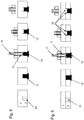
- FIGS. 6 to 9 are from the drawing level left to the drawing level right successive steps according to the FIGS. 1 to 5 shown in principle.
- the additional material body 12 is designed as a rivet, wherein the head portion 16 is designed tapering tapered.
- the head portion 16 is designed tapering tapered.
- the sleeve 9 does not dive into the cylindrical basic body encompassed by the sandwich element 2. Rather, the immersion is terminated spaced from the surface of the sandwich element 2.
- the cohesive joining plane of the additional material body 12 to the metal element 3 is arranged within the metal element 3.
- the riveted joint is a mechanical connection of the additional Material body 12 formed around sandwich element 2.
- the sandwich element 2 is connected to the metal element 3.
- the additional material body 12 is seen at its head portion 16 in cross-section U-shaped executed and has seen in cross-section two U-legs 21, between which a free space 22 which is bounded by a base 23.
- the free space 22 is filled by the material of the metal element which penetrates during the driving in, so that virtually an additional mechanical connection is produced.
- the U-legs 21 are designed so that the sleeve 9 contacted in the rotating immersion in the metal element 2 this. As can be seen, the sleeve 9 does not dive into the cylindrical basic body encompassed by the sandwich element 2. Rather, the immersion is spaced apart from the surface of the sandwich element 2, but also at a distance from the base 23 finished.
- the cohesive joining plane of the additional material body 12 to the metal element 3 is disposed within the metal element 3, wherein further U-legs 21 remain.
- the riveted joint forms a mechanical connection of the additional material body 12 to the sandwich element 2.
- the sandwich element 2 is connected to the metal element 3.
- the unplasticized U-legs 21 are further accommodated in the metal element 3 and form a further mechanical connection, however, to the metal element 3.
- the additional material body 12 has been introduced without pre-processing of the sandwich element 2 through this with its head part 16 engaging in the metal element 3, so that the rivet connection is produced.
- the sandwich element 2 is pre-machined and has a pre-hole 24.
- the pre-hole 24 is guided by the free surface of the sandwich element 2 of this completely sweeping in the direction of the metal element 3.
- the pre-hole 24 of the additional material body 12 is pressed by the feeding and holding device 7 and / or screwed.
- the additional material body 12 As to the FIGS. 1 to 5 described having an external thread, wherein the pre-hole 24 may have a corresponding internal thread.
- the pre-hole 24 is in its clear diameter favorably smaller than the outer diameter of the additional material body 12.
- the additional material body 12 can thus either be force fit pressed under press fit into the pre-hole or kraftformschlüssig screwed into the pre-hole 24 or screwed and pressed. Thus, the additional material body 12 is held securely in the sandwich element 2.
- the additional material body 12 has an outer diameter which corresponds to the outer diameter of the sleeve 9.
- the sleeve 9 penetrates through the metal element 3 into the additional material body 12 accommodated in the sandwich element, so that the additional material body 12, ie its head region 16, but also the metal element 3, are plasticized in the relevant area.
- the cohesive joining plane of the additional material body 12 is arranged to the metal element within the sandwich element 2, and not as to the FIGS. 6 and 7 described within the metal element 3. Nevertheless, it is also in the embodiment after FIG. 8 a hybrid compound.
- the additional material body 12 is wider than the sleeve 9.
- the sleeve 9 in the additional material body 12 ie in the head region 16, wherein, however, unplasticized webs 26 of the head portion 16 seen in cross section on both sides of the Einwirk Kunststoffs the sleeve 9 remain.
- the cohesive joining plane of the additional material body 12 to the metal element 3 is arranged within the sandwich element 2 but also within the remaining webs 26.
- FIG. 10 shows a cross section through the two interconnected elements 2 and 3 and through the additional material body 12th
- the metal element 2 is arranged in the drawing plane below. Above this, the sandwich element 2 is arranged.
- the additional material body 12 has, on its sandwich side, that is to say opposite the head region 16, the abutment flange 24 which bears against the sandwich element 2.
- the sleeve 9 is immersed in the additional material body 12, ie in the head region 16, which is shown by means of the stirring zone 27.
- the stirring zone 27 extends from the free surface of the metal element 2 therethrough, wherein seen in cross-section, the webs 26 can be seen left and right of the stirring zone 27.
- the proportions in FIG. 10 Of course, they are not true to scale and thus can be used for the selected representation of FIG. 9 differ.
- the stirring zone 27 is surrounded by a heat-affected zone 28. As in FIG. 10 it can be seen that this is spaced apart from the sandwich element 2 such that the thermal influence on the sandwich element 2 is negligible. In this respect, the properties of the sandwich element 2 are not impaired by the frictional heat, which plasticizes the metal element 3 but also the additional material body 12.
- the cohesive joining plane is in FIG. 10 indicated by the reference numeral 29. This lies within the sandwich element 3 and within the remaining webs 26th
Abstract
Die Erfindung betrifft ein Verfahren zum Herstellen einer Verbindung zwischen einem Sandwichelement (2) und einem Metallelement (3), wobei das Sandwichelement (2) eine zwischen zwei Deckelementen angeordnete artfremde Zwischenschicht aufweist, umfassend zumindest die Schritte: Bereitstellen des Sandwichelementes (2) und des Metallelementes (3), Übereinander Legen des Sandwichelementes und des Metallelementes, so dass diese zumindest bereichsweise überlappen, Beigeben eines zusätzlichen Materialkörpers (12) von der Sandwichelementseite (13) aus, wobei der zusätzliche Materialkörper (12) mit seinem Grundkörper vollständig in dem Sandwichelement (12) aufgenommen ist, und Durchführen eine Reibschweißprozesses von der Metallelementseite (14) aus, so dass eine Hybridverbindung gebildet ist, welche eine mechanische Verbindung des zusätzlichen Materialkörpers (12) zum Sandwichelement (2) und eine stoffschlüssige Verbindung des zusätzlichen Materialkörpers (12) zum Metallelement (3) aufweist.The invention relates to a method for producing a connection between a sandwich element (2) and a metal element (3), wherein the sandwich element (2) has a non-specific intermediate layer arranged between two cover elements, comprising at least the steps: Providing the sandwich element (2) and the metal element (3), Superimposing the sandwich element and the metal element so that they at least partially overlap, Inserting an additional material body (12) from the sandwich element side (13), the additional material body (12) with its basic body being completely accommodated in the sandwich element (12), and Performing a Reibschweißprozesses of the metal element side (14), so that a hybrid connection is formed, which is a mechanical connection of the additional material body (12) to the sandwich element (2) and a cohesive Connection of the additional material body (12) to the metal element (3).
Description
Die Erfindung betrifft ein Verfahren zum Herstellen einer Verbindung zwischen einem Sandwichelement und einem Metallelement. Die Erfindung betrifft aber auch eine Vorrichtung die zum Herstellen der Verbindung zwischen einem Sandwichelement und einem Metallelement eingerichtet ist.The invention relates to a method for producing a connection between a sandwich element and a metal element. However, the invention also relates to a device which is set up for producing the connection between a sandwich element and a metal element.
Derartige Sandwichelemente sind z.B. unter der Markenbezeichnung LITECOR® bekannt, und weisen einen Kunststoffkern auf, der von zwei Metalldeckblechen ummantelt wird. Das Sandwichelement ist also im Vergleich zu Vollstahlblechen gewichtsreduziert, aber auch sehr biege- und beulsteif. Solche Verbundwerkstoffe sind in der Fahrzeugindustrie zum Beispiel im Karosseriebereich als flächige Bauteile, wie zum Beispiel als Dach, Tür, Heckklappe oder Motorhaube einsetzbar und zeigen den Weg zu leistungsfähigen, und im Vergleich zu Metallelementen aus Stahl oder Leichtmetallen wie z.B. Aluminium oder Magnesium, weiter gewichtsreduzierten und kostenreduzierten Komponenten.Such sandwich elements are e.g. known under the brand name LITECOR®, and have a plastic core, which is covered by two metal cover sheets. The sandwich element is thus reduced in weight compared to solid steel sheets, but also very resistant to bending and bulging. Such composites are used in the automotive industry, for example in the body area as flat components, such as a roof, door, tailgate or hood and show the way to efficient, and compared to metal elements made of steel or light metals such. Aluminum or magnesium, further weight-reduced and cost-reduced components.
Metallelemente im Sinne der Erfindung sind Stahlbleche oder Leichtmetallbleche wie z.B. Aluminiumbleche oder Magnesiumbleche.Metal elements in the sense of the invention are steel sheets or light metal sheets such as e.g. Aluminum sheets or magnesium sheets.
Eine Baugruppe einer Kraftfahrzeugkarosserie mit einem Blechbauteil, das mit einem flächig daran angebrachten Verstärkungsbauteil aus einem Faserverbundwerkstoff verstärkt ist, ist in der
Aus der
Auch in der
Im Kraftfahrzeugbau, insbesondere bezüglich der Karosserie ist es von Vorteil, wenn diese besonders leicht ist. Dies spart Kraftstoff, und reduziert so auch die Emission schädlicher Gase, wie z.B. CO2. In unterschiedlichen Bereichen sind die Struktur-, also Karosseriebauteile an unterschiedlichste Belastungen auszulegen. Dabei müssen die Bauteile auch so hergestellt werden, dass bei möglichst wenig Materialverlust das höchste Leichtbaupotential erreichbar ist. In Bereichen, welche besonders hohen Belastungen ausgesetzt sind, können daher auch Verstärkungsmaßnahmen vorgesehen werden. Beispielsweise können die Bauteile aus einem Grundelement gebildet sein, und abschnittsweise Verdickungen als Verstärkungsmaßnahmen aufweisen. So genannte "tailored rolled blanks" sind bekannt. Tailored rolled blanks sind aber in der Herstellung sehr kompliziert, und insofern auch sehr kostenintensiv. Nachteilig ist auch, dass bei einem einzigen, auch geringen Walzfehler das gesamte Bauteil entsorgt werden muss, da dieses den Anforderungen dann nicht mehr entspricht. Denkbar ist aber auch, wenn an dem Grundelement separate Verstärkungselemente vorgesehen sind, welche aus faserverstärktem Kunststoff bestehen können. Wie bereits in der
In dem Artikel "
In der
Die eingangs genannten Sandwichelemente (LITECOR ®) eignen sich für den Einsatz als flächige Bauteile wie z.B. Türen, Dach, Heckklappe oder Motorhaube. Diese Bauteile sind üblicherweise mit anderen Bauteilen, wie z.B. Scharnieren oder Aufla-gerelementen verschraubt.The sandwich elements (LITECOR®) mentioned at the beginning are suitable for use as flat components, such as, for example, Doors, roof, tailgate or hood. These components are usually associated with other components, e.g. Hinged or Aufla-gerelementen bolted.
Der Erfindung liegt die Aufgabe zugrunde, ein Verfahren zum Verbinden eines Sandwichelementes mit einem Metallelement anzugeben, so dass ein Bauteil, insbesondere ein Kraftfahrzeugbauteil herstellbar ist, welches trotz reduziertem Herstellungsaufwand bei einer größtmöglichen Gewichtsbetrachtung die erforderlichen Steifigkeits-und/oder Crasherfordernisse erfüllt. Der Erfindung liegt aber auch die Aufgabe zugrunde, eine Vorrichtung anzugeben, die zur Durchführung des Verfahrens geeignet ist.The invention has for its object to provide a method for connecting a sandwich element with a metal element, so that a component, in particular a motor vehicle component can be produced, which meets the required stiffness and / or crash requirements despite reduced manufacturing costs with a maximum weight consideration. However, the invention is also based on the object of specifying a device which is suitable for carrying out the method.
Erfindungsgemäß wird die Aufgabe durch ein Verfahren mit den Merkmalen des Anspruchs 1 gelöst. Die vorrichtungstechnische Aufgabe wird durch eine Vorrichtung mit den Merkmalen des Anspruchs 9 gelöst. Die Unteransprüche geben jeweils vorteilhafte Ausführungsformen an.According to the invention the object is achieved by a method having the features of claim 1. The device-technical object is achieved by a device having the features of
Es ist darauf hinzuweisen, dass die in der nachfolgenden Beschreibung einzeln aufgeführten Merkmale sowie Maßnahmen in beliebiger, technisch sinnvoller Weise miteinander kombiniert werden können und weitere Ausgestaltungen der Erfindung aufzeigen.It should be noted that the features listed in the following description as well as measures in any technically meaningful way can be combined with each other and show other embodiments of the invention.
Erfindungsgemäß wird ein Verfahren zum Herstellen einer Verbindung zwischen einem Sandwichelement und einem Metallelement aufgezeigt, wobei das Sandwichelement eine zwischen zwei Deckelementen angeordnete, artfremde Zwischenschicht aufweist. Das erfindungsgemäße Verfahren umfasst zumindest die folgenden Schritte:
- Bereitstellen des Sandwichelementes und des Metallelementes;
- Übereinanderlegen des Sandwichelementes und des Metallelementes so, dass diese zumindest bereichsweise überlappen;
- Beigeben eines zusätzlichen Materialkörpers von der Sandwichelementseite her, wobei der zusätzliche Materialkörper mit seinem Grundkörper vollständig in dem Sandwichelement aufgenommen ist, und
- Durchführen eines Reibschweißprozesses von der dazu gegenüberliegenden Metallelementseite, so dass eine Hybridverbindung gebildet ist, welche eine mechanische Verbindung des zusätzlichen Materialkörpers zum Sandwichelement und eine stoffschlüssige Verbindung des zusätzlichen Materialkörpers zum Metallelement aufweist.
- Providing the sandwich element and the metal element;
- Overlay the sandwich element and the metal element so that they overlap at least partially;
- Beigeben an additional body of material from the sandwich element side, wherein the additional body of material is taken up with its main body completely in the sandwich element, and
- Performing a friction welding process from the opposite metal element side, so that a hybrid compound is formed, which has a mechanical connection of the additional material body to the sandwich element and a material connection of the additional material body to the metal element.
In bevorzugter Ausführung wird als Reibschweißprozess ein Reibrührschweißen, weiter bevorzugt ein widerauffüllendes Reibrührschweißen von der Metallelementseite aus durchgeführt. Das Metallelement im Sinne der Erfindung ist ein Stahlblech oder Leichtmetallblech, wie z.B. ein Aluminiumblech oder ein Magnesiumblech. Das Sandwichelement im Sinne der Erfindung weist eine zwischen zwei bevorzugt artgleichen Deckelementen angeordnete, artfremde Zwischenschicht auf. Die Deckelemente können Stahlbleche oder Leichtmetallbleche, wie z.B. Aluminiumbleche oder Magnesiumbleche sein, wobei die einander gegenüber liegenden Deckelemente auch aus jeweils unterschiedlichen Werkstoffen bestehen können. Die artfremde Zwischenschicht kann ein Kunststoff, z.B. ein Polymer sein. Ein Sandwichelement im Sinne der Erfindung kann auch ein Kohlenstofffaserverstärkter Kunststoff (CFK) sein. Mit der Erfindung können Kraftfahrzeugbauteile, wie z.B. A-, B-, C- oder D-Säulen aber auch andere Strukturelemente der Karoserie, wie z.B. Schweller, also Bauteile der gesamten Karosserie hergestellt werden. Diese gemäß der Erfindung hergestellten Bauteile sind bezogen auf Stahl oder Leichtmetalle kostengünstiger und bieten zudem Gewichtsvorteile. So kann das Metallelement als Grundelement angesehene werden, welches von dem Sandwichelement verstärkt wird, so dass das Sandwichelement als Verstärkungselement angesehen werden kann.In a preferred embodiment, the friction welding process is a friction stir welding, more preferably a refilling friction stir welding performed from the metal element side. The metal element according to the invention is a steel sheet or light metal sheet, such as an aluminum sheet or a magnesium sheet. The sandwich element according to the invention has a non-specific intermediate layer arranged between two preferably identical cover elements. The cover elements can steel sheets or light metal sheets, such as aluminum sheets or Be magnesium sheets, wherein the opposing cover elements can also consist of different materials. The foreign type intermediate layer may be a plastic, for example a polymer. A sandwich element according to the invention may also be a carbon fiber reinforced plastic (CFRP). With the invention, motor vehicle components, such as A-, B-, C- or D-pillars but also other structural elements of the body, such as sills, ie components of the entire body can be produced. These components produced according to the invention are less expensive in terms of steel or light metals and also offer weight advantages. Thus, the metal element may be regarded as a basic element, which is reinforced by the sandwich element, so that the sandwich element can be regarded as a reinforcing element.
Wesentlich ist bei der Erfindung, dass das Reibschweißen, also das bevorzugte wiederauffüllende Reibrührschweißen (RRSSW = Refill Friction Stir Spot Welding oder RFSEW = Refill Friction Stir Element Welding) von der zum Sandwichelement gegenüber liegenden Metallelementseite erfolgt. So ist eine thermische Beeinflussung des Sandwichmaterials trotz der hohen Reibungswärme auf der Metallelementseite vernachlässigbar. Denn es wird lediglich das Metallelement und der zusätzliche Materialkörper bereichsweise plastifiziert. So entsteht aber eine stoffschlüssige Verbindung des zusätzlichen Materialkörpers zum Metallelement, wobei der zusätzliche Materialkörper lagesicher in dem Sandwichelement aufgenommen ist. Der nicht plastifizierte Teil des zusätzlichen Materialkörpers verbleibt in seinem ursprünglich festen Zustand.It is essential in the invention that the friction welding, ie the preferred refilling friction stir welding (RRSSW = Refill Friction Stir Spot Welding or RFSEW = Refill Friction Stir Element Welding) takes place from the side facing the sandwich element metal element side. Thus, a thermal influence of the sandwich material despite the high frictional heat on the metal element side is negligible. For only the metal element and the additional material body is plasticized in some areas. But this results in a cohesive connection of the additional material body to the metal element, wherein the additional material body is securely received in the sandwich element. The non-plasticized part of the additional material body remains in its original solid state.
Damit der zusätzliche Materialkörper lagesicher in dem Sandwichelement aufgenommen werden kann, kann dieser als Niet ausgeführt sein. Idealer Weise kann also zunächst eine mechanische Verbindung, also eine Nietverbindung zwischen dem Sandwichelement und dem Metallelement hergestellt werden. Auf die dazu eingerichtete Vorrichtung wird später noch eingegangen. Der Niet wird von der Sandwichelementseite her, das Sandwichelement durchstoßend mit seiner Kopfseite in das Metallelement eingetrieben. Dabei greift der Niet mit seinem Kopfbereich in das Metallelement ein, durchstößt dieses aber nicht. Zielführend wird also zunächst eine mechanische Verbindung, also eine Nietverbindung zwischen dem Sandwichelement und dem Metallelement erzeugt. Der zusätzliche Materialkörper kann an seinem Grundkörper noch eine Art Außengewinde aufweisen, so dass die mechanische Verbindung weiter gesichert ist.So that the additional material body can be securely held in the sandwich element, this can be designed as a rivet. Ideally, therefore, first a mechanical connection, ie a riveted joint between the sandwich element and the metal element can be produced. On the device equipped for this will be discussed later. The rivet is driven from the sandwich element side, the sandwich element pierced with its head side in the metal element. The rivet engages with his head in the metal element, but pierces this not. As a result, a mechanical connection, that is, a riveted connection between the sandwich element and the metal element, is first produced. The additional material body can at his Base body still have a kind of external thread, so that the mechanical connection is further secured.
Zielführend ist, wenn das Sandwichelement so zu dem Metallelement positioniert wird, dass das Sandwichelement, also der Überlappungsbereich zwischen dem zusätzlichen Materialkörper und dem Metallelement angeordnet ist.When the sandwich element is positioned relative to the metal element, the objective is to arrange the sandwich element, that is to say the overlap region, between the additional material body and the metal element.
Der zusätzliche Materialkörper weist den zylindrischen Grundkörper auf und kann an seinem Kopfbereich spitz konusförmig ausgeführt sein. Der zusätzliche Materialkörper kann an seinem Kopfbereich aber auch U-Förmig oder eben ausgeführt sein. Natürlich sollen die genannten Ausführungen des Kopfbereiches nicht einschränkend sein.The additional material body has the cylindrical base body and can be made pointed cone-shaped at its head area. The additional material body may also be U-shaped or flat at its head area. Of course, the mentioned embodiments of the head area should not be limiting.
Gegenüberliegend zum Kopfbereich weist der zusätzliche Materialkörper eine Erweiterung des ansonsten zylindrischen Grundkörpers auf. Die Erweiterung kann auch als Anlageflansch bezeichnet werden, die sich an die freie Fläche des Sandwichelementes anlegt, und so quasi eine Eintreibsicherung bildet und ein zu tiefes Eindringen in das Metallelement verhindert. Der Anlageflansch kann in Umfangsrichtung gesehen unterbrochen sein, und muss also in Umfangsrichtung gesehen nicht durchgehend ausgeführt sein.Opposite the head area, the additional material body has an extension of the otherwise cylindrical base body. The extension can also be referred to as an abutment flange, which rests against the free surface of the sandwich element, thus virtually forming a Eintreibsicherung and prevents too deep penetration into the metal element. The abutment flange can be interrupted as seen in the circumferential direction, and therefore does not have to be continuous in the circumferential direction.
In einer weiter idealen Ausgestaltung der Erfindung kann in dem Sandwichelement ein Vorloch eingebracht werden, in welches der zusätzliche Materialkörper eingebracht wird. Das Vorloch erstreckt sich dabei vollständig von der freien Fläche ausgehend durch das gesamte Sandwichelement. Der zusätzliche Materialkörper weist einen zylindrischen Grundkörper mit einem bevorzugt ebenen Kopfbereich und einem dazu gegenüberliegenden Fußbereich auf, an dem optional ein Anlageflansch vorgesehen werden kann. Der zylindrische Grundkörper weist bis zum Kopfbereich eine Längserstreckung auf, welche der Längserstreckung des Vorlochs, also der Materialdicke des Sandwichelementes entspricht. Lediglich der an dem Fußbereich optional angeordnete Anlageflansch überragt das Vorloch, also die freie Oberfläche des Sandwichelementes. Das Vorloch kann im lichten Durchmesser kleiner ausgeführt sein, als der Außendurchmesser des zylindrischen Grundkörpers, so dass der zusätzliche Materialkörper quasi im Presssitz in das Vorloch einbringbar ist. Da der zusätzliche Materialkörper an die Materialdicke des Sandwichelementes angepasst ist, kommt dessen Kopfbereich direkt an der korrespondierenden Oberfläche des Metallelementes zu Anlage. Ersichtlich ist, dass so auf einen Anlageflansch verzichtet werden kann. Dieser kann dennoch vorgesehen werden, um ein zu tiefes eintreiben des zusätzlichen Materialkörpers von der Sandwichelementseite aus in das Metallelement hinein sicher vermeiden zu können. Mit diesem Vorgehen wird auf eine zunächst zu erstellende mechanische Verbindung zum Metallelement verzichtet, wobei der zusätzliche Materialkörper jedoch, wie auch schon zuvor Beschrieben, lagesicher in dem Sandwichelement aufgenommen ist. Es kann auch eine Schraubverbindung mittels korrespondierender Gewinde, also Innengewinde im Vorloch und Außengewinde an dem zylindrischen Grundkörper vorgesehen werden.In a further ideal embodiment of the invention, a pre-hole can be introduced into the sandwich element, in which the additional material body is introduced. The pre-hole extends completely from the free surface, starting through the entire sandwich element. The additional material body has a cylindrical basic body with a preferably flat head area and a foot area opposite thereto, on which optionally an abutment flange can be provided. The cylindrical base body has up to the head region on a longitudinal extent, which corresponds to the longitudinal extent of the Vorlochs, ie the material thickness of the sandwich element. Only the optionally arranged on the foot area abutment flange projects beyond the pre-hole, so the free surface of the sandwich element. The pre-hole can be made smaller in diameter than the outer diameter of the cylindrical base body so that the additional material body can be introduced into the pre-hole virtually in a press fit. Because of the extra Material body is adapted to the material thickness of the sandwich element, its head region comes directly to the corresponding surface of the metal element to plant. It can be seen that it is possible to dispense with an abutment flange. This can nevertheless be provided in order to be able to safely prevent too deep driving in of the additional material body from the sandwich element side into the metal element. With this procedure, a mechanical connection to the metal element which is initially to be created is dispensed with, although the additional material body, as already described above, is held securely in place in the sandwich element. It is also possible to provide a screw connection by means of corresponding threads, that is to say internal threads in the pre-hole and external threads on the cylindrical base body.
Der zusätzliche Materialkörper kann eine im Querschnitt gesehen ausgeführte Breite haben, welche der bevorzugten wiederrauffüllenden Reibrührschweißvorrichtung, also dem Außendurchmesser seiner Hülse entspricht. Möglich ist auch, wenn der zusätzliche Materialkörper breiter ausgeführt ist, so dass dessen äußerer Durchmesser die Hülse überragt.The additional material body may have a width, as seen in cross section, which corresponds to the preferred refillable friction stir welding device, that is, the outer diameter of its sleeve. It is also possible if the additional material body is made wider, so that its outer diameter projects beyond the sleeve.
Ist der zusätzliche Materialkörper von der Sandwichelementseite her zugegeben, wird die stoffschlüssige Verbindung mittels des Reibschweißens, also mittels des bevorzugten wiederauffüllenden Reibrührschweißens (RFSSW oder RFSEW) von der Metallelementseite ausgehend hergestellt.If the additional material body is added from the sandwich element side, the cohesive connection is produced by friction welding, ie by means of the preferred refilling friction stir welding (RFSSW or RFSEW), starting from the metal element side.
Zielführend ist, wenn der zusätzliche Materialkörper aus einem zum Metallelement artgleichen Werkstoff gebildet ist. Insofern kann der zusätzliche Materialkörper beispielsweise aus einem Stahl oder Leichtmetall, wie z.B. Aluminium oder Magnesium bestehen. So kann eine artgleiche Schweißverbindung hergestellt werden.Targeting is when the additional material body is formed from a same material to the metal element. In this respect, the additional body of material may be made of, for example, a steel or light metal, such as e.g. Aluminum or magnesium exist. Thus, a similar welding joint can be produced.
Es werden entsprechend der vorgesehenen Anzahl der zusätzlichen Materialkörper entsprechende Ansatzpunkte der Reibrührschweißvorrichtung vorgesehen. Auf die Reibrührschweißvorrichtung wird weiter unten noch eingegangen. Die formschlüssigen Verbindungsbereiche sind dabei bevorzugt ähnlich wie bei Punktschweißverbindungen zueinander beabstandet. An einer aktiven Seite des Metallelements, also an der Seite, an welcher die Reibrührschweißvorrichtung mit dem Reibrührschweißkopf angreift ist das Metallelement nach dem Zusammenfügen krater- und/oder erhebungsfrei im Wesentlichen eben ausgeführt (RFSSW oder RFSEW).It will be provided according to the intended number of additional material body corresponding starting points of the friction stir welding. The friction stir welding apparatus will be discussed later. The positive connection areas are preferably similar to each other as in spot welded joints. On an active side of the metal element, ie on the side at which the friction stir welding device with the friction stir welding head engages the metal element after joining crater and / or collection free essentially executed (RFSSW or RFSEW).
Idealer Weise wird der Reibrührschweißvorgang direkt gegenüberliegend zum zusätzlichen Materialkörper von der Metallelementseite aus durchgeführt. Die Reibrührschweißvorrichtung weist einen nicht-rotierbaren äußeren Klemmring, eine rotierbare Hülse und einen rotierbaren Stift auf. Mittels der rotierbaren Elemente, insbesondere mit der rotierbaren Hülse wird eine Rührzone erzeugt, also auch eine Vermischungszone zwischen dem zusätzlichen Materialkörper, idealer Weise lediglich seines Kopfbereiches mit dem Metallelement erzeugt. So wird das Metallelement aber auch der zusätzliche Materialkörper durch die entstehende Reibwärme plastifiziert. Von dem zusätzlichen Materialkörper wird zielführend lediglich der Kopfbereich plastifiziert, also nicht der gesamte zusätzliche Materialkörper. Dies ist günstig, da so der thermische Einfluss des Reibschweißens, also die entstehende Reibungswärme bezüglich des Sandwichelementes vernachlässigbar ist. Dieser Effekt wird noch weiter begünstigt, wenn der zusätzliche Materialkörper im Querschnitt gesehen breiter ist als die rotierbare Hülse der Reibrührschweißvorrichtung.Ideally, the friction stir welding process is performed directly opposite the additional material body from the metal element side. The friction stir welding apparatus has a non-rotatable outer clamping ring, a rotatable sleeve and a rotatable pin. By means of the rotatable elements, in particular with the rotatable sleeve, a stirring zone is produced, ie also a mixing zone between the additional material body, ideally only its head region with the metal element is produced. Thus, the metal element but also the additional material body is plasticized by the resulting frictional heat. Of the additional material body is purposefully plasticized only the head area, not the entire additional body of material. This is favorable since the thermal influence of the friction welding, that is to say the frictional heat generated with respect to the sandwich element, is negligible. This effect is further enhanced if the additional material body seen in cross-section is wider than the rotatable sleeve of the friction stir welding device.
Zweckmäßig ist, wenn bei dem Reibrührschweißvorgang die Rührzone durch das Metallelement hindurch bis in den Kopfbereich des zusätzlichen Materialkörpers geführt wird.It is expedient if, in the case of the friction stir welding process, the stirring zone is guided through the metal element and into the head region of the additional material body.
Ist der zusätzliche Materialkörper als Niet mit seinem Kopfbereich in dem Metallelement aufgenommen, ist es zielführend, wenn lediglich der in dem Metallelement aufgenommen Kopfbereich plastifiziert wird. Ist der Kopfbereich spitz konusförmig, wird der Kopfbereich quasi eingeebnet. Ist der Kopfbereich U-Förmig ausgeführt, werden lediglich die U-Schenkel plastifiziert. Jedoch ist die stoffschlüssige Fügeebene des zusätzlichen Materialkörpers zum Metallelement im Bereich des Metallelementes angeordnet.If the additional material body is received as a rivet with its head area in the metal element, it is expedient if only the head area accommodated in the metal element is plasticized. If the head area is pointedly cone-shaped, the head area is virtually leveled. If the head area is U-shaped, only the U-legs are plasticized. However, the cohesive joining plane of the additional material body to the metal element in the region of the metal element is arranged.
Ist der zusätzliche Materialkörper ohne mit seinem Kopfbereich in das Metallelement einzudringen in dem zuvor erstellten Vorloch aufgenommen, wird die Rührzone durch das Metallelement hindurch in den Kopfbereich des zusätzlichen Materialkörpers geführt. Dabei wird jedoch wiederum nicht der gesamte zusätzliche Materialkörper plastifiziert, sondern nur dessen Kopfbereich. Dabei ist die stoffschlüssige Fügeebene des zusätzlichen Materialkörpers zum Metallelement im Bereich des Sandwichelementes angeordnet.If the additional material body is received without penetrating its head region into the metal element in the previously created pre-hole, the stirring zone is guided through the metal element into the head region of the additional material body. However, again, not the entire additional material body plasticized, but only the head area. In this case, the cohesive joining plane of the additional material body to the metal element in the region of the sandwich element is arranged.
Günstiger Weise ist die Rührzone dabei im Querschnitt gesehen bevorzugt kleiner als die Breite des zusätzlichen Materialkörpers. Dies wurde oben bereits bezüglich des Außendurchmessers der Hülse welcher geringer ist als die Breite des zusätzlichen Materialkörpers erwähnt. So verbleibt ein äußerer, ringförmiger Bereich des zusätzlichen Materialkörpers, welcher nicht plastifiziert wird. Zielführend ist, wenn dieser ringförmige Bereich in seinen Abmessungen der zu erwartenden Wärmeeinflusszone um die Rührzone herum entspricht. Indem die Rührzone so vorteilhaft nicht nur in der Breite sondern auch in der Tiefe auf einen Teilkopfbereich des zusätzlichen Material körper begrenzt ist, wird der Wärmeeintrag in das Sandwichelement vernachlässigbar, da die Wärmeeinflusszone auf das Metallelement und den zusätzlichen Materialkörper begrenzt ist. Jedoch taucht die Reibschweißvorrichtung mit ihren rotierbaren Elementen in den Kopfbereich des zusätzlichen Materialkörpers ein, so dass die Rührzone in den Kopfbereich geführt ist. So wird eine stoffschlüssige Fügeebene des Metallelementes zum zusätzlichen Materialkörper erzeugt, welche im Bereich des Sandwichelementes angeordnet ist.Conveniently, the stirring zone is seen in cross-section preferably smaller than the width of the additional material body. This has already been mentioned above with respect to the outer diameter of the sleeve, which is smaller than the width of the additional material body. This leaves an outer, annular region of the additional material body, which is not plasticized. It is expedient if this annular region corresponds in its dimensions to the expected heat-affected zone around the stirring zone. By the stirring zone is so advantageous limited not only in width but also in depth to a partial head region of the additional material body, the heat input into the sandwich element is negligible, since the heat affected zone is limited to the metal element and the additional material body. However, the friction welding device dips with its rotatable elements in the head region of the additional material body, so that the stirring zone is guided in the head area. Thus, a cohesive joining plane of the metal element to the additional material body is produced, which is arranged in the region of the sandwich element.
Mit den beschriebenen Vorgehensweisen ist eine stoffschlüssige Verbindung des Metallelements zum zusätzlichen Materialkörper erzeugt. Die beiden Elemente werden quasi miteinander verschweißt. Dadurch dass der zusätzliche Materialkörper entweder als Niet von dem Sandwichelement aus eingebracht ist, oder als zylindrischer Körper in einem Vorloch des Sandwichelementes lagesicher aufgenommen oder z.B. eingepresst ist (Presspassung), liegt also eine Hybridverbindung vor, die eine mechanische Verbindung und eine stoffschlüssige Verbindung aufweist. So wird eine Verbindung erzeugt, welche eine höchste Verbindungsgüte nicht nur hinsichtlich auftretender Scheer- und Rissbeanspruchungen hat. So können auch Strukturbauteile wesentlich flexibler gestaltet werden.With the described procedures, a cohesive connection of the metal element to the additional material body is produced. The two elements are virtually welded together. Characterized in that the additional material body is introduced either as a rivet of the sandwich element, or as a cylindrical body in a pre-hole of the sandwich element taken in a secure position or e.g. is pressed (interference fit), so there is a hybrid compound, which has a mechanical connection and a material connection. Thus, a connection is generated, which has a highest quality of connection not only with regard to occurring shearing and cracking stresses. This also makes it possible to design structural components much more flexibly.
Der vorrichtungstechnische Teil der Aufgabe wird durch eine Vorrichtung mit den Merkmalen des Anspruchs 9 gelöst. Die erfindungsgemäße Vorrichtung ist zur Durchführung des zuvor beschriebenen Verfahrens zur Verbindung eines Sandwichelementes mit einem Metallelemente eingerichtet, und weist eine Reibschweißvorrichtung, bevorzugt eine Reibrührschweißvorrichtung, weiter bevorzugt eine wiederauffüllende Reibrührschweißvorrichtung auf. Im Folgenden wird der Einfachheit wegen der Begriff Reibschweißvorrichtung genannt, welcher jeweils die bevorzugten Ausgestaltungen umfasst. Zielführend ist vorgesehen, dass die Reibschweißvorrichtung an einem Ende eines Tragarms angeordnet ist, an dessen gegenüberliegenden Ende zumindest eine Halte- und Zuführvorrichtung für zumindest einen zusätzlichen Materialkörper angeordnet ist.The device-technical part of the object is achieved by a device having the features of
So kann von einer Seite, nämlich von der Sandwichelementseite aus der zusätzliche Materialkörper zugeführt werden, wobei von der dazu gegenüber liegenden Seite, also von der Metallelementseite die Reibschweißvorrichtung angreifen kann, so dass der Reibschweißprozess durchgeführt werden kann.Thus, the additional material body can be supplied from one side, namely from the sandwich element side, wherein the friction welding device can act on the side lying opposite thereto, ie on the metal element side, so that the friction welding process can be carried out.
Günstig ist, wenn der Tragarm C-förmig ausgeführt ist, so dass die Zuführ- und Haltevorrichtung und die Reibschweißvorrichtung einander gegenüber angeordnet sind.It is favorable if the support arm is C-shaped, so that the supply and holding device and the friction welding device are arranged opposite each other.
Zweckmäßig ist, wenn die Zuführ- und Haltevorrichtung ein Förderelement aufweist, mit dem eine mechanische Verbindung herstellbar ist. Die mechanische Verbindung kann eine Nietverbindung oder eine Presspassung sein, wobei auch eine zusätzliche Schraubverbindung denkbar ist. Für eine Nietverbindung ist der zusätzliche Materialkörper als Niet ausgeführt, welcher von dem Förderelement der Zuführ- und Haltevorrichtung das Sandwichelement durchstoßend mit seinem Kopfbereich in das Metallelement eingetrieben wird. Für eine Presspassung wird zunächst ein Vorloch in das Sandwichelement eingebracht, in welches der zusätzliche Materialkörper eingepresst wird. Dazu kann das Förderelement genutzt werden, wobei dessen Leistung reduziert sein kann, oder die Zuführ- und Haltevorrichtung ist mit einer entsprechenden Leistung ausgeführt, so dass auf das Förderelement verzichtet werden kann. Wie zuvor erwähnt können auch korrespondierende Gewinde vorgesehen werden, oder nur der zusätzliche Materialkörper weist eine Art Außengewinde, also quasi Eingriffzähne auf, welche die gewählte mechanische Verbindung weiter verstärken.It is expedient if the feeding and holding device has a conveying element with which a mechanical connection can be produced. The mechanical connection may be a rivet connection or a press fit, wherein an additional screw connection is also conceivable. For a riveted joint, the additional material body is designed as a rivet, which is driven by the conveying element of the feeding and holding device, the sandwich element piercing with its head portion in the metal element. For a press fit, a pre-hole is first introduced into the sandwich element, in which the additional material body is pressed. For this purpose, the conveying element can be used, wherein its performance can be reduced, or the feeding and holding device is designed with a corresponding performance, so that it is possible to dispense with the conveying element. As mentioned above, corresponding threads can also be provided, or only the additional material body has a kind of external thread, that is to say quasi-engagement teeth, which further reinforce the selected mechanical connection.
Günstig ist, dass sowohl die Reibschweißvorrichtung als auch die Zuführ- und Haltevorrichtung relativ zum Tragarm, also relativ zu dem jeweiligen Ende an dem die betreffenden Vorrichtungen angeordnet sind aus einer Ruheposition in eine Arbeitsposition und zurück bewegbar sind. In der Ruheposition sind die beiden Vorrichtung so zueinander beabstandet, dass die einander zumindest überlappenden Elemente, also das Sandwichelement und das Metallelement in einen Zwischenraum bringbar ist. Aus der Ruheposition sind die beiden Vorrichtungen bevorzugt gleichzeitig in die Arbeitsposition überführbar. In dieser stehen beide Vorrichtung in Kontakt mit den jeweiligen Oberflächen des betreffenden Elementes. Die Reibschweißvorrichtung steht also in Kontakt mit der freien Oberfläche des Metallelementes. Die Zuführ- und Haltevorrichtung steht in Kontakt mit der freien Oberfläche des Sandwichelementes. Beide Vorrichtungen sind einander gegenüberliegend angeordnet. Ist der zusätzliche Materialkörper in dem Sandwichelement aufgenommen, also zugeführt, beginnt der Reibschweißprozess, wobei die Zuführ- und Haltevorrichtung die Haltefunktion übernimmt. Dabei kann auch der zusätzliche Materialkörper zusätzlich gehalten werden, wobei auch ein Andrücken des Sandwichelementes an das Metallelement möglich ist. Bei dem Reibschweißprozess wird die Hülse zunächst zusammen mit dem Stift unter Rotation in das Metallelement eingetaucht, wodurch das Material entsprechend plastifiziert wird. Ist der zusätzliche Materialkörper ein Niet, welcher mit seinem Kopfbereich innerhalb des Metallelementes angeordnet ist, wird so der Kopfbereich durch die entstehende Wärme ebenfalls plastifiziert. Liegt der zusätzliche Materialkörper mit seinem Kopfbereich an der korrespondierenden Oberfläche des Metallelementes an, taucht die Hülse rotierend in den Kopfbereich des zusätzlichen Materialkörpers ein, und plastifiziert so das Metallelement als auch den betrefflichen Kopfbereichabschnitt. So entsteht jeweils die stoffschlüssige Fügeebene des Metallelementes zum zusätzlichen Materialkörper innerhalb des Sandwichelementes oder innerhalb des Metallelementes. Ab einer gewissen Eintauchtiefe wird der Stift entgegengesetzt zur Eintauchbewegung der Hülse bewegt, also quasi zurückgezogen. Gleichzeitig mit Zurückziehen der rotierbaren Hülse in ihre Ausgangsposition wird der rotierbare Stift wiederum entgegengesetzt in Richtung zur freien Oberfläche des Metallelementes geführt, so dass die freie Oberfläche nach dem widerauffüllenden Reibrührschweißprozess kraterfrei und eben ist. Die Reibschweißvorrichtung aber auch die Zuführ-und Haltevorrichtung wird in ihre jeweilige Ruheposition überführt. Es können nun weitere Verbindungen erstellt werden, oder die einander verbundenen Elemente (Sandwichelement/Metallelement), also das gebildete Bauteil, insbesondere ein Strukturbauteil eines Kraftfahrzeuges wird aus der Vorrichtung entnommen wenn die notwendigen Verbindungen erstellt sind.It is favorable that both the friction welding device and the feeding and holding device relative to the support arm, ie relative to the respective end to which the respective Devices are arranged from a rest position to a working position and are movable back. In the rest position, the two devices are spaced from each other so that the at least overlapping elements, so the sandwich element and the metal element can be brought into a space. From the rest position, the two devices are preferably simultaneously transferred to the working position. In this both devices are in contact with the respective surfaces of the element concerned. The friction welding device is thus in contact with the free surface of the metal element. The feeding and holding device is in contact with the free surface of the sandwich element. Both devices are arranged opposite each other. If the additional material body is received in the sandwich element, that is, fed, the friction welding process begins, wherein the feeding and holding device assumes the holding function. In this case, the additional material body can be additionally held, with a pressing of the sandwich element to the metal element is possible. In the friction welding process, the sleeve is first dipped into the metal element together with the pin, thereby plastifying the material accordingly. If the additional material body is a rivet, which is arranged with its head area inside the metal element, then the head area is also plasticized by the resulting heat. When the additional material body with its head area abuts against the corresponding surface of the metal element, the sleeve dips in rotation into the head area of the additional material body, thereby plasticizing the metal element as well as the relevant head area section. Thus, in each case the cohesive joining plane of the metal element to the additional material body within the sandwich element or within the metal element is formed. From a certain immersion depth, the pin is moved in the opposite direction to the immersion movement of the sleeve, so quasi retracted. Simultaneously with retraction of the rotatable sleeve to its original position, the rotatable pin is again guided in the opposite direction towards the free surface of the metal element, so that the free surface is crater-free and even after the refilling friction-stir welding process. The friction welding but also the feeding and holding device is transferred to their respective rest position. It is now possible to create further connections, or the interconnected elements (sandwich element / metal element), ie the formed component, in particular a Structural component of a motor vehicle is removed from the device when the necessary connections are made.
Weitere vorteilhafte Einzelheiten und Wirkungen der Erfindung sind im Folgenden anhand von in den Figuren dargestellten Ausführungsbeispielen näher erläutert. Es zeigen
- Fig. 1
- einen Querschnitt einer Vorrichtung zur Verbindung eines Sandwichelementes mit einem Metallelement in einer Ruheposition,
- Fig. 2 bis Fig. 5
- die Vorrichtung aus
Figur 1 mit aufeinanderfolgenden Schritten, - Fig. 6
- das erfindungsgemäße Verfahren in aufeinander folgenden Schritten in einer ersten Ausgestaltungsvariante,
- Fig. 7
- das erfindungsgemäße Verfahren in aufeinander folgenden Schritten in einer zweiten Ausgestaltungsvariante,
- Fig. 8
- das erfindungsgemäße Verfahren in aufeinander folgenden Schritten in einer dritten Ausgestaltungsvariante,
- Fig. 9
- das erfindungsgemäße Verfahren in aufeinander folgenden Schritten in einer vierten Ausgestaltungsvariante,
- Fig. 10
- einen Querschnitt durch zwei verbundene Elemente als Einzelheit zu dem
Ausführungsbeispiel nach Figur 9 .
- Fig. 1
- a cross-section of an apparatus for connecting a sandwich element with a metal element in a rest position,
- Fig. 2 to Fig. 5
- the device off
FIG. 1 with successive steps, - Fig. 6
- the inventive method in successive steps in a first embodiment variant,
- Fig. 7
- the inventive method in successive steps in a second embodiment variant,
- Fig. 8
- the inventive method in successive steps in a third embodiment variant,
- Fig. 9
- the inventive method in successive steps in a fourth embodiment variant,
- Fig. 10
- a cross section through two connected elements as a detail to the embodiment according to
FIG. 9 ,
In den unterschiedlichen Figuren sind gleiche Teile stets mit denselben Bezugszeichen versehen, weswegen diese in der Regel auch nur einmal beschrieben werden.In the different figures, the same parts are always provided with the same reference numerals, which is why these are usually described only once.
Das Sandwichelement 2 weist eine zwischen zwei bevorzugt artgleichen Deckelementen angeordnete, artfremde Zwischenschicht auf. Die Deckelemente können aus einem Stahlblech oder aus einem Leichtmetallblech, wie z.B. aus einem Aluminiumblech oder Magnesiumblech gebildet sein. Die artfremde Zwischenschicht kann ein Kunststoff, beispielsweise ein Polymer sein. Das Metallelement 3 kann ein Stahlblech oder ein Leichtmetallblech, wie zum Beispiel ein Aluminiumblech oder ein Magnesiumblech sein.The
Die Vorrichtung 1 weist einen Tragarm 4 auf, der beispielhaft C-Förmig ausgeführt ist. An einem seiner Enden weist der Tragarm 4 eine Reibschweißvorrichtung, bevorzugt eine Reibrührschweißvorrichtung, weiter bevorzugt eine wiederauffüllende Reibrührschweißvorrichtung 6 auf. An dem dazu gegenüberliegenden Ende des Tragarms 4 ist eine Zuführ- und Haltevorrichtung 7 angeordnet.The device 1 has a
Die wiederauffüllende Reibrührschweißvorrichtung 6 weist einen äußere Klemmring 8, eine rotierbare Hülse 9 und einen rotierbaren Stift 11 auf.The refilling friction
Zumindest ein zusätzlicher Materialkörper 12, bevorzugt mehrere zusätzliche Materialkörper 12 sind in der Zuführ- und Haltevorrichtung 7 erkennbar. Die zusätzlichen Materialkörper 12 können magazinartig zugeführt werden. Die Zuführ-und Haltevorrichtung 7 kann ein Förderelement aufweisen. Mit dem Förderelement kann eine Nietverbindung hergestellt werden. Dazu ist der zusätzliche Materialkörper 12 bei dem Ausführungsbeispiel nach
Wie in
Das Sandwichelement 2 und das Metallelement 3 sind so aufeinander gelegt, dass zumindest eine Überlappung gebildet ist, in welcher die gewünschte Verbindung herstellbar ist. In
Beide Vorrichtungen 6 und 7 sind relativ zu dem Tragarm 4 aus der Ruheposition in eine Arbeitsposition überführbar, die in den
Bei dem In
Wie in den
Bei dem Herstellen der mechanischen Verbindung des Sandwichelementes 2 zum Metallelement 3 mittels des zusätzlichen Materialkörpers 12 dient die Wiederauffüllende Reibrührschweißvorrichtung 6 als Widerlager, und drückt das Metallelement 3 in Richtung zum Sandwichelement 2.In establishing the mechanical connection of the
In
Mit der Erfindung wird also eine Hybridverbindung zwischen dem Sandwichelement 2 und dem Metallelement 2 erzeugt, welches eine mechanische Verbindung des zusätzlichen Materialkörpers 12 zum Sandwichelement 2 und zugleich eine stoffschlüssige Verbindung des zusätzlichen Materialkörpers 12 zum Metallelement 3 aufweist.With the invention, therefore, a hybrid connection between the
In den
Bei dem in
Bei dem in
Bei den in den
Das Vorloch 24 ist von der freien Oberfläche des Sandwichelementes 2 dieses vollständig durchgreifend in Richtung zum Metallelement 3 geführt. In das Vorloch 24 wird der zusätzliche Materialkörper 12 von der Zuführ- und Haltevorrichtung 7 eingepresst und/oder eingeschraubt. Zum Einschrauben kann der zusätzliche Materialkörper 12 wie zu den
Das Vorloch 24 ist in seinem lichten Durchmesser günstiger Weise kleiner als der Außendurchmesser des zusätzlichen Materialkörpers 12. Der zusätzliche Materialkörper 12 kann also entweder kraftschlüssig unter Presspassung in das Vorloch eingepresst werden oder kraftformschlüssig in das Vorloch 24 eingeschraubt oder eingedreht und eingepresst werden. So ist der zusätzliche Materialkörper 12 lagesicher in dem Sandwichelement 2 gehalten.The pre-hole 24 is in its clear diameter favorably smaller than the outer diameter of the
Bei dem Ausführungsbeispiel gemäß
Bei dem in
Das Metallelement 2 ist in der Zeichnungsebene unten angeordnet. Darüber ist das Sandwichelement 2 angeordnet. Der zusätzliche Materialkörper 12 weist an seiner Sandwichseite, also gegenüberliegend zum Kopfbereich 16 den Anlageflansch 24 auf, welcher an dem Sandwichelement 2 anliegt.The
In das Metallelement 2 ist die Hülse 9 bis in den zusätzlichen Materialkörper 12, also in dessen Kopfbereich 16 eingetaucht, was mittels der Rührzone 27 dargestellt ist. Die Rührzone 27 erstreckt sich von der freien Oberfläche des Metallelementes 2 durch dieses hindurch, wobei im Querschnitt gesehen links und rechts der Rührzone 27 die Stege 26 erkennbar sind. Die Größenverhältnisse in
Aufgrund der entstehenden Reibungswärme ist die Rührzone 27 von einer Wärmeeinflusszone 28 umgeben. Wie in
Die stoffschlüssige Fügeebene ist in
- 11
- Vorrichtungcontraption
- 22
- Sandwichelementsandwich element
- 33
- Metallelementmetal element
- 44
- TragarmBeam
- 55
- 66
- wiederauffüllende Reibrührschweißvorrichtungrefilling friction stir welding device
- 77
- Zuführ- und HaltevorrichtungFeeding and holding device
- 88th
- Äußerer KlemmringOuter clamping ring
- 99
- Hülseshell
- 1010
- 1111
- Stiftpen
- 1212
- Zusätzlicher MaterialkörperAdditional material body
- 1313
- SandwichelementseiteSandwich element side
- 1414
- MetallelementseiteMetal element side
- 1515
- 1616
- Kopfbereichhead area
- 1717
- Rotationspfeilrotation arrow
- 1818
- Anlageflanschabutment
- 1919
- konusförmige Spitzecone-shaped tip
- 2020
- 2121
- U-SchenkelU-leg
- 2222
- Freiraumfree space
- 2323
- BasisBase
- 2424
- Vorlochpilot hole
- 2525
- 2626
- unlpastifizierte Stegeunplastered bars
- 2727
- Rührzonestirring zone
- 2828
- WärmeeinflusszoneHeat affected zone
- 2929
- stoffschlüssige Fügeebenecohesive joining plane
Claims (10)
als Reibschweißprozess ein Reibrührschweißen, bevorzugt ein wiederauffüllendes Reibrührschweißen durchgeführt wird.Method according to claim 1, characterized in that
friction stir welding, a friction stir welding, preferably a refilling friction stir welding is performed.
bei dem Reibschweißprozess lediglich das Metallelement (3) zumindest bereichsweise und ein Kopfbereich (16) des zusätzlichen Materialkörpers (16) plastifiziert werden.A method according to claim 1 or 2, characterized in that
in the friction welding process, only the metal element (3) is plastified at least in regions and a head region (16) of the additional material body (16).
dadurch gekennzeichnet, dass
der zusätzliche Materialkörper (12) als Niet ausgeführt ist, welcher in das Sandwichelement (2) dieses durchgreifend mit seinem Kopfbereich (16) in das Metallelement (3) eingreifend eingetrieben wird.Method according to one of the preceding claims,
characterized in that
the additional material body (12) is designed as a rivet, which is drivingly driven into the sandwich element (2) with its head region (16) engaging in the metal element (3).
dadurch gekennzeichnet, dass
in das Sandwichelement (2) ein Vorloch (24) eingebracht wird, in welches der zusätzliche Materialkörper (12) eingebracht wird.Method according to one of the preceding claims,
characterized in that
in the sandwich element (2) a pre-hole (24) is introduced, in which the additional material body (12) is introduced.
dadurch gekennzeichnet, dass
der zusätzliche Materialkörper (12) aus einem zum Metallelement (3) artgleichen Werkstoff gebildet ist.Method according to one of the preceding claims,
characterized in that
the additional material body (12) is formed from a material that is similar to the metal element (3).
gekennzeichnet durch
eine stoffschlüssige Fügeebene (29) des zusätzlichen Materialkörpers (12) zum Metallelement (2) welche innerhalb des Metallelementes (3) angeordnet ist.Method according to one of the preceding claims,
marked by
a cohesive joining plane (29) of the additional material body (12) to the metal element (2) which is arranged within the metal element (3).
gekennzeichnet durch
eine stoffschlüssige Fügeebene (29) des zusätzlichen Materialkörpers (12) zum Metallelement (2) welche innerhalb des Sandwichelementes (2) angeordnet ist.Method according to one of claims 1 to 6,
marked by
a cohesive joining plane (29) of the additional material body (12) to the metal element (2) which is arranged within the sandwich element (2).
Applications Claiming Priority (1)
| Application Number | Priority Date | Filing Date | Title |
|---|---|---|---|
| DE102016205924.6A DE102016205924A1 (en) | 2016-04-08 | 2016-04-08 | Method for producing a hybrid connection and device therefor |
Publications (2)
| Publication Number | Publication Date |
|---|---|
| EP3228416A1 true EP3228416A1 (en) | 2017-10-11 |
| EP3228416B1 EP3228416B1 (en) | 2020-05-06 |
Family
ID=58410122
Family Applications (1)
| Application Number | Title | Priority Date | Filing Date |
|---|---|---|---|
| EP17162236.8A Active EP3228416B1 (en) | 2016-04-08 | 2017-03-22 | Method and device for producing a hybrid connection and body component produced thereof |
Country Status (4)
| Country | Link |
|---|---|
| US (1) | US10807146B2 (en) |
| EP (1) | EP3228416B1 (en) |
| CN (1) | CN107262911B (en) |
| DE (1) | DE102016205924A1 (en) |
Citations (8)
| Publication number | Priority date | Publication date | Assignee | Title |
|---|---|---|---|---|
| US20100089977A1 (en) | 2008-10-14 | 2010-04-15 | Gm Global Technology Operations, Inc. | Friction stir welding of dissimilar metals |
| EP2329905B1 (en) | 2009-12-03 | 2012-05-30 | Helmholtz-Zentrum Geesthacht Zentrum für Material- und Küstenforschung GmbH | Method for joining metal and plastic workpieces |
| DE102011114306A1 (en) * | 2011-09-23 | 2013-03-28 | Audi Ag | Method for joining two fiber-reinforced plastic components by metallic joining element, involves driving setting bolt through fiber-reinforced plastic-components as joint element and subsequently through metal sheet lying in joint area |
| EP2585247A1 (en) * | 2010-06-23 | 2013-05-01 | EJOT GmbH & Co. KG | Connecting element for a friction-welded connection for connecting at least two panel-like components |
| DE102012203888A1 (en) | 2012-03-13 | 2013-09-19 | Bayerische Motoren Werke Aktiengesellschaft | Component for motor vehicle body, has metal sheet component reinforced with planar amplification component and connected with another metal sheet component in region of recess by joining process |
| EP2689882A2 (en) | 2012-07-26 | 2014-01-29 | Tata Technologies Pte Ltd | An apparatus and process for joining homogeneous and heterogeneous materials with customized interface properties |
| WO2015106244A2 (en) * | 2014-01-13 | 2015-07-16 | Brigham Young University | Friction bit joining of materials using a friction rivet |
| DE102014011599A1 (en) * | 2014-08-02 | 2016-02-04 | Audi Ag | Method for joining at least two components |
Family Cites Families (18)
| Publication number | Priority date | Publication date | Assignee | Title |
|---|---|---|---|---|
| US6769595B2 (en) * | 2000-12-20 | 2004-08-03 | Alcoa Inc. | Friction plunge riveting |
| US6742697B2 (en) * | 2002-04-29 | 2004-06-01 | The Boeing Company | Joining of structural members by friction plug welding |
| US6854634B2 (en) * | 2002-05-14 | 2005-02-15 | The Boeing Company | Method of manufacturing rivets having high strength and formability |
| JP4150383B2 (en) * | 2004-04-13 | 2008-09-17 | 新日本製鐵株式会社 | Fracture prediction apparatus, method, computer program, and computer-readable recording medium for spot welds |
| DE102004034498A1 (en) * | 2004-07-16 | 2006-02-16 | Ejot Gmbh & Co. Kg | Method for friction welding of components |
| US7677299B2 (en) * | 2004-11-10 | 2010-03-16 | Wen-Chun Zheng | Nearly isothermal heat pipe heat sink |
| CN100518469C (en) * | 2005-06-10 | 2009-07-22 | 郑文春 | Nearly isothermal heat pipe heat sink and process for making the same |
| KR100711778B1 (en) * | 2005-12-26 | 2007-04-25 | 재단법인 포항산업과학연구원 | Apparatus for friction stir spot welding |
| DE102009038697A1 (en) | 2009-08-24 | 2011-03-17 | Ejot Gmbh & Co. Kg | Device for connecting at least two plates |
| CN101817142A (en) * | 2010-05-20 | 2010-09-01 | 上海交通大学 | Self-piercing frictional rivet welding connecting device |
| CN103237648A (en) * | 2010-12-08 | 2013-08-07 | 丰田自动车株式会社 | Method of connecting members |
| CN102615508A (en) * | 2012-03-26 | 2012-08-01 | 郑州大学 | Metal plate rotating friction riveting method |
| CN103240564B (en) * | 2013-04-26 | 2016-04-13 | 上海交通大学 | Machinery-solid phase composite connecting device and attaching method thereof |
| DE102013020082A1 (en) * | 2013-11-29 | 2015-06-03 | Böllhoff Verbindungstechnik GmbH | A welding auxiliary joining part, a die for setting the welding auxiliary joining part, a joining method for the welding auxiliary joining part, and a manufacturing method for the welding auxiliary joining part and the die |
| DE202014002917U1 (en) * | 2014-04-07 | 2014-05-26 | Stirtec Gmbh | Spot welding gun |
| KR102529491B1 (en) * | 2016-12-22 | 2023-05-04 | 현대자동차주식회사 | A friction rivet for joining different materials |
| KR20180073348A (en) * | 2016-12-22 | 2018-07-02 | 현대자동차주식회사 | Method for connecting different materials by friction bit joining |
| US10590979B2 (en) * | 2017-01-24 | 2020-03-17 | Ford Global Technologies, Llc | Corrosion protection for mechanical joints |
-
2016
- 2016-04-08 DE DE102016205924.6A patent/DE102016205924A1/en not_active Withdrawn
-
2017
- 2017-03-22 EP EP17162236.8A patent/EP3228416B1/en active Active
- 2017-04-06 CN CN201710220884.5A patent/CN107262911B/en active Active
- 2017-04-07 US US15/481,551 patent/US10807146B2/en active Active
Patent Citations (8)
| Publication number | Priority date | Publication date | Assignee | Title |
|---|---|---|---|---|
| US20100089977A1 (en) | 2008-10-14 | 2010-04-15 | Gm Global Technology Operations, Inc. | Friction stir welding of dissimilar metals |
| EP2329905B1 (en) | 2009-12-03 | 2012-05-30 | Helmholtz-Zentrum Geesthacht Zentrum für Material- und Küstenforschung GmbH | Method for joining metal and plastic workpieces |
| EP2585247A1 (en) * | 2010-06-23 | 2013-05-01 | EJOT GmbH & Co. KG | Connecting element for a friction-welded connection for connecting at least two panel-like components |
| DE102011114306A1 (en) * | 2011-09-23 | 2013-03-28 | Audi Ag | Method for joining two fiber-reinforced plastic components by metallic joining element, involves driving setting bolt through fiber-reinforced plastic-components as joint element and subsequently through metal sheet lying in joint area |
| DE102012203888A1 (en) | 2012-03-13 | 2013-09-19 | Bayerische Motoren Werke Aktiengesellschaft | Component for motor vehicle body, has metal sheet component reinforced with planar amplification component and connected with another metal sheet component in region of recess by joining process |
| EP2689882A2 (en) | 2012-07-26 | 2014-01-29 | Tata Technologies Pte Ltd | An apparatus and process for joining homogeneous and heterogeneous materials with customized interface properties |
| WO2015106244A2 (en) * | 2014-01-13 | 2015-07-16 | Brigham Young University | Friction bit joining of materials using a friction rivet |
| DE102014011599A1 (en) * | 2014-08-02 | 2016-02-04 | Audi Ag | Method for joining at least two components |
Non-Patent Citations (2)
| Title |
|---|
| "Friction spot joining of aluminum AA6181-T4 and carbon fiberreinforced poly(phenylene sulfide): Effects of process parameters on the microstructure and mechanical strength", MATERIAL AND DESIGN, vol. 66, 2015, pages 437 - 445 |
| THYSSENKRUPP: "EINSATZPOTENZIAL VON LITECOR IN DER KAROSSERIE", ATZ EXTRA, 31 October 2014 (2014-10-31), pages 108 - 111, XP055399938, Retrieved from the Internet <URL:https://incarplus.thyssenkrupp.com/navigator_atz_pdf/ATZ_InCar_plus_Karosserie_Potenzialanalyse_LITECOR.pdf> [retrieved on 20170821] * |
Also Published As
| Publication number | Publication date |
|---|---|
| DE102016205924A1 (en) | 2017-10-12 |
| CN107262911B (en) | 2021-06-01 |
| US20170291215A1 (en) | 2017-10-12 |
| EP3228416B1 (en) | 2020-05-06 |
| US10807146B2 (en) | 2020-10-20 |
| CN107262911A (en) | 2017-10-20 |
Similar Documents
| Publication | Publication Date | Title |
|---|---|---|
| EP2722124B1 (en) | Method for joining at least two components with a resistance welding element, and device for carrying out the method and resulting composite component | |
| EP1716959B1 (en) | Process of and device for friction stir welding of at least two workpieces of different materials with a slidable pin and current passing through the workpieces | |
| WO2012041515A1 (en) | Method and joining tool for joining two metal elements by riveting and welding | |
| DE102014204449A1 (en) | Method for joining components, one of which consists of a fiber-reinforced plastic | |
| DE102016224431B4 (en) | Body component | |
| EP2481569A1 (en) | Motor vehicle component and method for manufacturing same | |
| DE102009013265B4 (en) | Method and tools for making a mixing assembly | |
| DE102007030929B9 (en) | Axle carrier for motor vehicles | |
| DE102005038463A1 (en) | Carrier member for a vehicle bodywork, as a box profile of two part-shells, has an inner reinforcement profile of two shells bonded to the part-shells | |
| DE10015713A1 (en) | Component, in particular for a vehicle | |
| DE102016007698B4 (en) | Process for the production of a composite component | |
| WO2013171180A1 (en) | Arrangement of components, vehicle seat, and production method | |
| DE102015213633B3 (en) | Method for joining at least two components by means of friction spot welding and a friction element designed as a joining element and joining device | |
| DE102008028686A1 (en) | Composite component i.e. steel-aluminum composite component, for use in e.g. A-column of motor vehicle, has plastic foil arranged in partial area of sealing flange between steel shells and aluminum component | |
| DE102017005123A1 (en) | Assembly of at least two workpieces and method for joining at least two workpieces to an assembly | |
| EP3228416B1 (en) | Method and device for producing a hybrid connection and body component produced thereof | |
| DE102015215823A1 (en) | Combination of flow forming and resistance welding technology for a two-stage joining process | |
| DE102014112138A1 (en) | Motor vehicle body in mixed construction and method for producing a motor vehicle body in mixed construction | |
| DE102021206369A1 (en) | Method of assembling an automobile body | |
| DE102009036558B4 (en) | chassis assembly | |
| DE102016200357A1 (en) | Method for joining at least two components by means of a hardened joining element | |
| WO1999037523A1 (en) | Method for joining vehicle parts and vehicle parts joined according to said method | |
| DE102014001230B4 (en) | Elongated body support of a vehicle body | |
| DE102018116271A9 (en) | Method of connecting | |
| DE102013224685A1 (en) | Method and device for producing a composite component |
Legal Events
| Date | Code | Title | Description |
|---|---|---|---|
| PUAI | Public reference made under article 153(3) epc to a published international application that has entered the european phase |
Free format text: ORIGINAL CODE: 0009012 |
|
| STAA | Information on the status of an ep patent application or granted ep patent |
Free format text: STATUS: THE APPLICATION HAS BEEN PUBLISHED |
|
| AK | Designated contracting states |
Kind code of ref document: A1 Designated state(s): AL AT BE BG CH CY CZ DE DK EE ES FI FR GB GR HR HU IE IS IT LI LT LU LV MC MK MT NL NO PL PT RO RS SE SI SK SM TR |
|
| AX | Request for extension of the european patent |
Extension state: BA ME |
|
| STAA | Information on the status of an ep patent application or granted ep patent |
Free format text: STATUS: REQUEST FOR EXAMINATION WAS MADE |
|
| 17P | Request for examination filed |
Effective date: 20180411 |
|
| RBV | Designated contracting states (corrected) |
Designated state(s): AL AT BE BG CH CY CZ DE DK EE ES FI FR GB GR HR HU IE IS IT LI LT LU LV MC MK MT NL NO PL PT RO RS SE SI SK SM TR |
|
| RIC1 | Information provided on ipc code assigned before grant |
Ipc: F16B 19/04 20060101ALI20191220BHEP Ipc: B23K 101/00 20060101ALN20191220BHEP Ipc: F16B 5/04 20060101ALI20191220BHEP Ipc: B23K 103/16 20060101ALN20191220BHEP Ipc: B23K 20/22 20060101ALI20191220BHEP Ipc: B23K 20/12 20060101AFI20191220BHEP Ipc: B21J 15/00 20060101ALI20191220BHEP |
|
| GRAP | Despatch of communication of intention to grant a patent |
Free format text: ORIGINAL CODE: EPIDOSNIGR1 |
|
| STAA | Information on the status of an ep patent application or granted ep patent |
Free format text: STATUS: GRANT OF PATENT IS INTENDED |
|
| GRAS | Grant fee paid |
Free format text: ORIGINAL CODE: EPIDOSNIGR3 |
|
| INTG | Intention to grant announced |
Effective date: 20200211 |
|
| GRAA | (expected) grant |
Free format text: ORIGINAL CODE: 0009210 |
|
| STAA | Information on the status of an ep patent application or granted ep patent |
Free format text: STATUS: THE PATENT HAS BEEN GRANTED |
|
| AK | Designated contracting states |
Kind code of ref document: B1 Designated state(s): AL AT BE BG CH CY CZ DE DK EE ES FI FR GB GR HR HU IE IS IT LI LT LU LV MC MK MT NL NO PL PT RO RS SE SI SK SM TR |
|
| REG | Reference to a national code |
Ref country code: GB Ref legal event code: FG4D Free format text: NOT ENGLISH |
|
| REG | Reference to a national code |
Ref country code: CH Ref legal event code: EP Ref country code: AT Ref legal event code: REF Ref document number: 1266001 Country of ref document: AT Kind code of ref document: T Effective date: 20200515 |
|
| REG | Reference to a national code |
Ref country code: IE Ref legal event code: FG4D Free format text: LANGUAGE OF EP DOCUMENT: GERMAN |
|
| REG | Reference to a national code |
Ref country code: DE Ref legal event code: R096 Ref document number: 502017005101 Country of ref document: DE |
|
| REG | Reference to a national code |
Ref country code: LT Ref legal event code: MG4D |
|
| REG | Reference to a national code |
Ref country code: NL Ref legal event code: MP Effective date: 20200506 |
|
| PG25 | Lapsed in a contracting state [announced via postgrant information from national office to epo] |
Ref country code: SE Free format text: LAPSE BECAUSE OF FAILURE TO SUBMIT A TRANSLATION OF THE DESCRIPTION OR TO PAY THE FEE WITHIN THE PRESCRIBED TIME-LIMIT Effective date: 20200506 Ref country code: LT Free format text: LAPSE BECAUSE OF FAILURE TO SUBMIT A TRANSLATION OF THE DESCRIPTION OR TO PAY THE FEE WITHIN THE PRESCRIBED TIME-LIMIT Effective date: 20200506 Ref country code: NO Free format text: LAPSE BECAUSE OF FAILURE TO SUBMIT A TRANSLATION OF THE DESCRIPTION OR TO PAY THE FEE WITHIN THE PRESCRIBED TIME-LIMIT Effective date: 20200806 Ref country code: GR Free format text: LAPSE BECAUSE OF FAILURE TO SUBMIT A TRANSLATION OF THE DESCRIPTION OR TO PAY THE FEE WITHIN THE PRESCRIBED TIME-LIMIT Effective date: 20200807 Ref country code: IS Free format text: LAPSE BECAUSE OF FAILURE TO SUBMIT A TRANSLATION OF THE DESCRIPTION OR TO PAY THE FEE WITHIN THE PRESCRIBED TIME-LIMIT Effective date: 20200906 Ref country code: PT Free format text: LAPSE BECAUSE OF FAILURE TO SUBMIT A TRANSLATION OF THE DESCRIPTION OR TO PAY THE FEE WITHIN THE PRESCRIBED TIME-LIMIT Effective date: 20200907 Ref country code: FI Free format text: LAPSE BECAUSE OF FAILURE TO SUBMIT A TRANSLATION OF THE DESCRIPTION OR TO PAY THE FEE WITHIN THE PRESCRIBED TIME-LIMIT Effective date: 20200506 |
|
| PG25 | Lapsed in a contracting state [announced via postgrant information from national office to epo] |
Ref country code: LV Free format text: LAPSE BECAUSE OF FAILURE TO SUBMIT A TRANSLATION OF THE DESCRIPTION OR TO PAY THE FEE WITHIN THE PRESCRIBED TIME-LIMIT Effective date: 20200506 Ref country code: HR Free format text: LAPSE BECAUSE OF FAILURE TO SUBMIT A TRANSLATION OF THE DESCRIPTION OR TO PAY THE FEE WITHIN THE PRESCRIBED TIME-LIMIT Effective date: 20200506 Ref country code: BG Free format text: LAPSE BECAUSE OF FAILURE TO SUBMIT A TRANSLATION OF THE DESCRIPTION OR TO PAY THE FEE WITHIN THE PRESCRIBED TIME-LIMIT Effective date: 20200806 Ref country code: RS Free format text: LAPSE BECAUSE OF FAILURE TO SUBMIT A TRANSLATION OF THE DESCRIPTION OR TO PAY THE FEE WITHIN THE PRESCRIBED TIME-LIMIT Effective date: 20200506 |
|
| PG25 | Lapsed in a contracting state [announced via postgrant information from national office to epo] |
Ref country code: NL Free format text: LAPSE BECAUSE OF FAILURE TO SUBMIT A TRANSLATION OF THE DESCRIPTION OR TO PAY THE FEE WITHIN THE PRESCRIBED TIME-LIMIT Effective date: 20200506 Ref country code: AL Free format text: LAPSE BECAUSE OF FAILURE TO SUBMIT A TRANSLATION OF THE DESCRIPTION OR TO PAY THE FEE WITHIN THE PRESCRIBED TIME-LIMIT Effective date: 20200506 |
|
| PG25 | Lapsed in a contracting state [announced via postgrant information from national office to epo] |
Ref country code: RO Free format text: LAPSE BECAUSE OF FAILURE TO SUBMIT A TRANSLATION OF THE DESCRIPTION OR TO PAY THE FEE WITHIN THE PRESCRIBED TIME-LIMIT Effective date: 20200506 Ref country code: IT Free format text: LAPSE BECAUSE OF FAILURE TO SUBMIT A TRANSLATION OF THE DESCRIPTION OR TO PAY THE FEE WITHIN THE PRESCRIBED TIME-LIMIT Effective date: 20200506 Ref country code: CZ Free format text: LAPSE BECAUSE OF FAILURE TO SUBMIT A TRANSLATION OF THE DESCRIPTION OR TO PAY THE FEE WITHIN THE PRESCRIBED TIME-LIMIT Effective date: 20200506 Ref country code: ES Free format text: LAPSE BECAUSE OF FAILURE TO SUBMIT A TRANSLATION OF THE DESCRIPTION OR TO PAY THE FEE WITHIN THE PRESCRIBED TIME-LIMIT Effective date: 20200506 Ref country code: DK Free format text: LAPSE BECAUSE OF FAILURE TO SUBMIT A TRANSLATION OF THE DESCRIPTION OR TO PAY THE FEE WITHIN THE PRESCRIBED TIME-LIMIT Effective date: 20200506 Ref country code: SM Free format text: LAPSE BECAUSE OF FAILURE TO SUBMIT A TRANSLATION OF THE DESCRIPTION OR TO PAY THE FEE WITHIN THE PRESCRIBED TIME-LIMIT Effective date: 20200506 Ref country code: EE Free format text: LAPSE BECAUSE OF FAILURE TO SUBMIT A TRANSLATION OF THE DESCRIPTION OR TO PAY THE FEE WITHIN THE PRESCRIBED TIME-LIMIT Effective date: 20200506 |
|
| REG | Reference to a national code |
Ref country code: DE Ref legal event code: R097 Ref document number: 502017005101 Country of ref document: DE |
|
| PG25 | Lapsed in a contracting state [announced via postgrant information from national office to epo] |
Ref country code: PL Free format text: LAPSE BECAUSE OF FAILURE TO SUBMIT A TRANSLATION OF THE DESCRIPTION OR TO PAY THE FEE WITHIN THE PRESCRIBED TIME-LIMIT Effective date: 20200506 Ref country code: SK Free format text: LAPSE BECAUSE OF FAILURE TO SUBMIT A TRANSLATION OF THE DESCRIPTION OR TO PAY THE FEE WITHIN THE PRESCRIBED TIME-LIMIT Effective date: 20200506 |
|
| PLBE | No opposition filed within time limit |
Free format text: ORIGINAL CODE: 0009261 |
|
| STAA | Information on the status of an ep patent application or granted ep patent |
Free format text: STATUS: NO OPPOSITION FILED WITHIN TIME LIMIT |
|
| 26N | No opposition filed |
Effective date: 20210209 |
|
| PG25 | Lapsed in a contracting state [announced via postgrant information from national office to epo] |
Ref country code: SI Free format text: LAPSE BECAUSE OF FAILURE TO SUBMIT A TRANSLATION OF THE DESCRIPTION OR TO PAY THE FEE WITHIN THE PRESCRIBED TIME-LIMIT Effective date: 20200506 |
|
| PG25 | Lapsed in a contracting state [announced via postgrant information from national office to epo] |
Ref country code: MC Free format text: LAPSE BECAUSE OF FAILURE TO SUBMIT A TRANSLATION OF THE DESCRIPTION OR TO PAY THE FEE WITHIN THE PRESCRIBED TIME-LIMIT Effective date: 20200506 |
|
| REG | Reference to a national code |
Ref country code: CH Ref legal event code: PL |
|
| REG | Reference to a national code |
Ref country code: BE Ref legal event code: MM Effective date: 20210331 |
|
| PG25 | Lapsed in a contracting state [announced via postgrant information from national office to epo] |
Ref country code: CH Free format text: LAPSE BECAUSE OF NON-PAYMENT OF DUE FEES Effective date: 20210331 Ref country code: LU Free format text: LAPSE BECAUSE OF NON-PAYMENT OF DUE FEES Effective date: 20210322 Ref country code: LI Free format text: LAPSE BECAUSE OF NON-PAYMENT OF DUE FEES Effective date: 20210331 Ref country code: IE Free format text: LAPSE BECAUSE OF NON-PAYMENT OF DUE FEES Effective date: 20210322 Ref country code: FR Free format text: LAPSE BECAUSE OF NON-PAYMENT OF DUE FEES Effective date: 20210331 |
|
| PG25 | Lapsed in a contracting state [announced via postgrant information from national office to epo] |
Ref country code: BE Free format text: LAPSE BECAUSE OF NON-PAYMENT OF DUE FEES Effective date: 20210331 |
|
| REG | Reference to a national code |
Ref country code: AT Ref legal event code: MM01 Ref document number: 1266001 Country of ref document: AT Kind code of ref document: T Effective date: 20220322 |
|
| PG25 | Lapsed in a contracting state [announced via postgrant information from national office to epo] |
Ref country code: HU Free format text: LAPSE BECAUSE OF FAILURE TO SUBMIT A TRANSLATION OF THE DESCRIPTION OR TO PAY THE FEE WITHIN THE PRESCRIBED TIME-LIMIT; INVALID AB INITIO Effective date: 20170322 |
|
| PG25 | Lapsed in a contracting state [announced via postgrant information from national office to epo] |
Ref country code: CY Free format text: LAPSE BECAUSE OF FAILURE TO SUBMIT A TRANSLATION OF THE DESCRIPTION OR TO PAY THE FEE WITHIN THE PRESCRIBED TIME-LIMIT Effective date: 20200506 |
|
| P01 | Opt-out of the competence of the unified patent court (upc) registered |
Effective date: 20230620 |
|
| PG25 | Lapsed in a contracting state [announced via postgrant information from national office to epo] |
Ref country code: AT Free format text: LAPSE BECAUSE OF NON-PAYMENT OF DUE FEES Effective date: 20220322 |
|
| PG25 | Lapsed in a contracting state [announced via postgrant information from national office to epo] |
Ref country code: MK Free format text: LAPSE BECAUSE OF FAILURE TO SUBMIT A TRANSLATION OF THE DESCRIPTION OR TO PAY THE FEE WITHIN THE PRESCRIBED TIME-LIMIT Effective date: 20200506 |
|
| PGFP | Annual fee paid to national office [announced via postgrant information from national office to epo] |
Ref country code: DE Payment date: 20240209 Year of fee payment: 8 Ref country code: GB Payment date: 20240208 Year of fee payment: 8 |