EP3228168A1 - Saatgutleitung für eine sämaschine - Google Patents
Saatgutleitung für eine sämaschine Download PDFInfo
- Publication number
- EP3228168A1 EP3228168A1 EP17401029.8A EP17401029A EP3228168A1 EP 3228168 A1 EP3228168 A1 EP 3228168A1 EP 17401029 A EP17401029 A EP 17401029A EP 3228168 A1 EP3228168 A1 EP 3228168A1
- Authority
- EP
- European Patent Office
- Prior art keywords
- seed
- line
- spring element
- seed line
- spring
- Prior art date
- Legal status (The legal status is an assumption and is not a legal conclusion. Google has not performed a legal analysis and makes no representation as to the accuracy of the status listed.)
- Granted
Links
Images



Classifications
-
- A—HUMAN NECESSITIES
- A01—AGRICULTURE; FORESTRY; ANIMAL HUSBANDRY; HUNTING; TRAPPING; FISHING
- A01C—PLANTING; SOWING; FERTILISING
- A01C7/00—Sowing
- A01C7/20—Parts of seeders for conducting and depositing seed
- A01C7/206—Seed pipes
-
- A—HUMAN NECESSITIES
- A01—AGRICULTURE; FORESTRY; ANIMAL HUSBANDRY; HUNTING; TRAPPING; FISHING
- A01C—PLANTING; SOWING; FERTILISING
- A01C7/00—Sowing
- A01C7/08—Broadcast seeders; Seeders depositing seeds in rows
- A01C7/081—Seeders depositing seeds in rows using pneumatic means
- A01C7/082—Ducts, distribution pipes or details thereof for pneumatic seeders
Definitions
- the invention relates to a seed line for a sowing machine according to the preamble of claim 1.
- Such a seed line for a seeder is known in practice.
- This seed line is attached by means of a nut-like clamp connection or a bayonet-type connection to the metering device. So here is a positive and secured by rotation, tool-like connection of the seed line with the metering use.
- the created by rotation of components of the nut-like clamping connection or a bayonet-type compound tool-like connection with rotatable locking elements can rub especially after prolonged use or become stiff, which then inevitably requires the use of tools for releasing the connecting element.
- the invention has for its object to provide a simplified and easy separation of the seed line in the dosing without the use of rotatable locking elements.
- the seed line has at least one separation point with tool-free opening and again to be closed connecting element. As a result of this measure is dispensed twisted locking elements.
- the seed line is assigned a spring element holding the connecting element in the connecting and closed position.
- a simple embodiment of the separation point of the seed line with good connection properties is achieved in that the connecting element as cone-shaped cooperating father and mother part is formed.
- the connecting element as cone-shaped cooperating father and mother part is formed.
- a good fit of the connecting parts of the seed line to be connected and disconnected is achieved at the point of separation, whereby the correct fit of the connecting parts of the seed line to be connected and disconnected at the point of separation is ensured only by the spring bias of the spring element in its connecting position.
- Other fasteners are not required.
- the separating point designed in this way can be easily and safely opened and closed again without tools via this connecting element according to the invention.
- the cone-like connecting element is held exclusively by the spring element in the connecting and closing position.
- the spring element is formed as part of the seed line.
- the spring element is tubular.
- the spring element may be formed as a rubber spring and / or rubber spring-like tubular element.
- a manual actuation element is arranged on the separable part of the seed line.
- the separable part of the seed line is removably arranged.
- a simplified and easy separation of the seed line in the area of the metering device without the use of rotatable locking elements is provided in that the seed line divides at least one, preferably at least two separation points, the seed line into a first and a second region, that between the two separation points of the seed line an intermediate line of the seed line, the first and bridging the second region of the seed line, it is arranged that connecting elements between the regions of the seed line and the intermediate line are opened without tools and have to be closed again, that the connecting elements are formed in the region of the separation points as a father and mother parts which co-operate in a cone-like manner, in that at least one of the connecting elements is associated with a spring element holding the seed lines and the intermediate line in the connecting and closed positions.
- the seed line can be opened at the intended separation point in a simple manner.
- the removable intermediate line is held by the spring element in its connecting and closing position. Furthermore, a secure hold and centering of the intermediate line in the seed line is ensured by the cone-shaped father and mother parts in conjunction with the spring element. At the same time there is a good seal of the intermediate line to the rest of the seed line.
- the spring element is tubular and surrounds the intermediate line.
- a simple design of the spring element can be achieved in that the spring element is designed as a rubber spring, foam element and / or rubber-like pipe element.
- the intermediate line is removably disposed in the seed line.
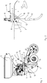
- the Einzelkornsäaggregat 1 has a frame 2, which is to be mounted in a known and therefore not shown manner on a crossbar of trained as a seeder sowing machine. In a known manner, several Einzelkornsäaggregate 1 spaced next to each other are arranged on the crossbar. On the frame 2 of the Einzelkornsäaggregates 1, the coulter unit 3, the separating device 4 and the seed hopper 5 is arranged. Between the separating device 4 and formed as a share unit 3 dispensing and / or storage device, the separable trained seed line 6 is arranged. The seed line 6 has the separation point 7 with the tool to open and again to be closed connecting element 8.
- the connecting element 7 has the cooperating cone-like male part 9 and the cone-like female part 10. Below the connecting element 7, the tube-shaped spring element 11 is arranged in the seed line 6. This spring element 11 is formed as a rubber spring and rubber spring-like tubular element and forms part of the seed line 6. In the upper region 12 of the lower part 13 of the separable seed line 6, designed as a hand lever manual actuating element 14 is arranged. In the exemplary embodiment, the cone-like male part 9 of the connecting element 7 is located at the lower end of the upper separable part of the seed line 6, while the female part 10 of the connecting element 7 is located at the upper end of the separable part of the seed line 6. The separable part 13 of the seed line 6 can be arranged removably in the seed line 6.
- the spring element 11 has in the closed position of the seed line 6, as in the Fig. 1 and 2 shown, a bias, so that the spring element 11 presses the separable part 13 of the seed line 6 in the direction of the connecting element 7.
- the connecting element 7 of the seed line 6 is held in the closed position exclusively by the bias of the spring element 11.
- the separable part 13 of the seed line 6 can be pivoted back into its closed position. If the separable part 13 of the seed line 6 is pivoted so far that the female part 10 is located in the vicinity of the male part 9, the separable part 13 of the seed line 6 is pressed down by pressing on the manual operating element 14 in the direction of arrow 15 and further pivoted so far until the female part 10 is located directly below the male part 9. In this position, the pressure force is removed from the manual actuating element 14 so that the male part 9 snaps into the female part 10 a. This alone restores the connection of the seed line 6 in the region of the connecting element 8.
- connection point 7 can be dispensed with by the inventive design on an additional bayonet or screw-like locking element in the region of the connection point 7.
- the Einzelkornsäaggregat 101 has a frame 102 which is to be mounted in a known and therefore not shown manner on a crossbar of trained as a seeder sowing machine. In a known manner a plurality of Einzelkornsäaggregate 101 spaced apart from each other on a transverse bar, not shown.
- the share unit 103, the separating device 104 and the seed hopper 105 is arranged on the frame 102 of the Einzelkornsäaggregates 101.
- the separable trained seed line 106 is arranged between the separating device 104 and formed as a share unit 103 dispensing and / or storage device.
- the seed line 106 has the two separation points 107 and 108 with the interposed and removable intermediate line 109.
- the intermediate line 109 and the seed line 106 have, in the region of the separation points 107 and 108, cooperating cone-like male parts 110 and female parts 111.
- the tubular spring element 120 is arranged in the seed line 106.
- This spring element 120 is formed as a rubber spring and rubber spring-like tubular element and surrounds the intermediate line 109 in its lower region.
- the spring element 120 can also be designed as a foam element.
- the seed line 106 is divided over the two separation points 107 and 108 into a first and a second region.
- the intermediate line 109 of the seed line 106 which connects the first and second regions of the seed line 106 in a bridging manner, is arranged.
- the separation points 107 and 108 are, as described above, tool-free opening and re-closing, formed as a cone-like cooperating father 110 and nut parts 111.
- the lower separation point 7 and designed as father 110 and mother parts 111 connecting elements between the seed line 106 and the intermediate line 109 is held in the connecting and closed position retaining spring element 120.
- the seed line 106 can be easily opened at the intended trend points 107 and 108 by removing the intermediate line 109.
- the intermediate element 109 Via the spring element 120, the intermediate element 109 is held in its connecting and closed position. Furthermore, a secure hold and centering of the intermediate line 109 in the seed line 106 is ensured by the cone-shaped and cooperating father 110 and nut parts 110 in conjunction with the spring element 120. At the same time there is a good seal of the intermediate line 109 to the other areas of the seed line 106th
- the conically configured connecting elements 110 and 111 exclusively hold the intermediate line 109 in the seed line 106 in the connecting and closed position by the spring element 120.
- the spring element 120 is assigned to the intermediate line 109 and formed conically on the side of the seed line 106 facing side. This results in advantageous assignment of the spring element 120 with a good seal between the intermediate line 109 and the Saautgut effet 106 in the region of the separation points 107 and 108th
- the intermediate line 109 can be removed from the seed line 106.
- the spring element 120 has in the closed position of the seed line 6, as in the Fig. 6 . 7 , and 9 to 11 shown, a bias, so that the spring element 120 holds the separable part 109 of the seed line 106 between the separation points 107 and 108 of the seed line.
- a bias so that the spring element 120 holds the separable part 109 of the seed line 106 between the separation points 107 and 108 of the seed line.
- the intermediate line 109 of the seed line 106 can be re-inserted into its closed position between the separation points 107 and 108, so that the connection of the seed line 106 in the region between the separation points 107 and 108th is restored.
Landscapes
- Life Sciences & Earth Sciences (AREA)
- Soil Sciences (AREA)
- Environmental Sciences (AREA)
- Sowing (AREA)
Abstract
Description
- Die Erfindung betrifft eine Saatgutleitung für eine Sämaschine gemäß des Oberbegriffes des Patentanspruches 1.
- Eine derartige Saatgutleitung für eine Sämaschine ist in der Praxis bekannt. Diese Saatleitung ist mittels eine mutterartigen Klemmverbindung oder einer bajonettartigen Verbindung an der Dosiervorrichtung befestigt. Hier findet also eine formschlüssige und durch Verdrehung gesicherte, werkzeugartige Verbindung der Saatgutleitung mit der Dosiervorrichtung Verwendung. Die durch Verdrehung von Bauteilen der mutterartigen Klemmverbindung oder einer bajonettartigen Verbindung geschaffene werkzeugartige Verbindung mit verdrehbaren Verriegelungselementen kann besonders nach längerem Gebrauch reiben oder schwergängig werden, welches dann zwangsläufig den Einsatz von Werkzeug zum Lösen des Verbindungselementes verlangt.
- Der Erfindung liegt die Aufgabe zugrunde, ein vereinfachtes und leichtes Trennen der Saatgutleitung im Bereich der Dosiervorrichtung ohne den Einsatz von verdrehbaren Verriegelungselementen zu schaffen.
- Diese Aufgabe wird erfindungsgemäß dadurch gelöst, dass die Saatgutleitung zumindest eine Trennstelle mit werkzeuglos zu öffnendem und wieder zu verschließendem Verbindungselement aufweist. Infolge dieser Maßnahme wird auf zu verdrehende Verriegelungselemente verzichtet.
- Dieses lässt sich erfindungsgemäß dadurch erreichen, dass der Saatgutleitung ein das Verbindungselement in Verbindungs- und Schließstellung haltendes Federelement zugeordnet ist. Mittels des die Saatgutleitung an der vorgesehenen Trennstelle in Verbindungs- und Schließstellung haltende Federelement wird allein durch die Federvorspannung des Federelementes in seiner Verbindungsposition gehalten.
- Eine einfache Ausgestaltung der Trennstelle der Saatgutleitung mit guten Verbindungseigenschaften wird dadurch erreicht, dass das Verbindungselement als konusartiges zusammenwirkendes Vater- und Mutterteil ausgebildet ist. Hierdurch wird ein guter Sitz der miteinander zu verbindenden und zu trennenden Verbindungsteile der Saatgutleitung an der Trennstelle erreicht, wobei der korrekte Sitz der miteinander zu verbindenden und zu trennenden Verbindungsteile der Saatgutleitung an der Trennstelle nur durch die Federvorspannung des Federelementes in seiner Verbindungsposition gewährleistet wird. Weitere Verbindungselemente sind nicht erforderlich. Die so ausgestaltete Trennstelle ist über dieses erfindungsgemäße Verbindungselement leicht und sicher werkzeuglos zu öffnen und wieder zu verschließen.
- Somit wird das konusartige Verbindungselement ausschließlich durch das Federelement in Verbindungs- und Schließstellung gehalten.
- Eine integrierte Anordnung des Federelementes in die Saatgutleitung lässt sich dadurch erreichen, dass das Federelement als Bestandteil der Saatgutleitung ausgebildet ist. In vorteilhafter Weise ist das Federelement rohrförmig ausgebildet. Hierbei kann das Federelement als Gummifeder und/oder gummifederartiges Rohrelement ausgebildet sein.
- Um die Saatgutleitung auch bei beengten Bauverhältnissen an schwer zugänglichen Stellen leicht trennen oder wieder zusammensetzen zu können. Ist vorgesehen, dass an dem trennbaren Teil der Saatgutleitung ein Handbetätigungselement angeordnet ist.
- In einer weiteren Ausgestaltung kann vorgesehen sein, dass der trennbare Teil der Saatgutleitung herausnehmbar angeordnet ist.
- In einer weiteren Ausgestaltung wird, ein vereinfachtes und leichtes Trennen der Saatgutleitung im Bereich der Dosiervorrichtung ohne den Einsatz von verdrehbaren Verriegelungselementen dadurch geschaffen, dass die Saatgutleitung zumindest eine, vorzugsweise zumindest zwei Trennstellen, die Saatgutleitung in einen ersten und einen zweiten Bereich teilt, aufweist, dass zwischen den zwei Trennstellen der Saatgutleitung eine Zwischenleitung der Saatgutleitung, die den ersten und zweiten Bereich der Saatgutleitung überbrückend verbindet, angeordnet ist, dass den Trennstellen werkzeuglos zu öffnende und wieder zu verschließende Verbindungselemente zwischen den Bereichen der Saatgutleitung und der Zwischenleitung zugeordnet sind, dass die Verbindungselemente im Bereich der Trennstellen als konusartig zusammenwirkende Vater- und Mutterteile ausgebildet sind, dass zumindest einem der Verbindungselemente ein die Saatgutleitungen und die Zwischenleitung in Verbindungs- und Schließstellung haltendes Federelement zugeordnet ist.
- Infolge dieser Maßnahmen wird zunächst auf das Verdrehen der Verriegelungselemente verzichtet. Hierdurch lässt sich die Saatgutleitung an der vorgesehenen Trennstelle in einfacher Weise öffnen. Die herausnehmbare Zwischenleitung wird durch das Federelement in seine Verbindungs- und Schließstellung gehalten. Weiterhin wird ein sicherer Halt und Zentrierung der Zwischenleitung in der Saatgutleitung durch die konusartig ausgebildeten Vater- und Mutterteile in Verbindung mit dem Federelement gewährleistet. Gleichzeitig ergibt sich eine gute Abdichtung der Zwischenleitung zu dem übrigen Bereich der Saatgutleitung.
- Ein einfacher Halt der Zwischenleitung in der Saatgutleitung sowie die Möglichkeit einer einfachen Demontage und Herausnahme der Zwischenleitung an der Trennstelle der Saatgutleitung wird dadurch gewährleistet, dass die konusartig ausgestalteten Verbindungselemente ausschließlich durch das Federelement in Verbindungs- und Schließstellung gehalten werden.
- Eine vorteilhafte Zuordnung des Federelemente zu der Zwischenleitung wird dadurch erreicht, dass das Federelement der Zwischenleitung zugeordnet und auf der der Saatgutleitung zugewandten Seite konisch ausgebildet ist.
- Um das Federelement in einfacher Weise der Zwischenleitung zuordnen zu können, ist vorgesehen, dass das Federelement rohrförmig ausgebildet ist und die Zwischenleitung umschließt.
- Eine einfache Ausbildung des Federelementes lässt sich dadurch erreichen, dass das Federelement als Gummifeder, Schaumstoffelement und/oder gummifederartiges Rohrelement ausgebildet ist.
- Um beispielsweise Verstopfungen in der Saatgutleitung in einfacher Weise beseitigen zu können, ist vorgesehen, dass die Zwischenleitung in der Saatgutleitung herausnehmbar angeordnet ist.
- Weitere Einzelheiten der Erfindung sind der Beispielsbeschreibung und den Zeichnungen zu entnehmen. Die Zeichnungen zeigen
- Fig.1
- ein Einzelkornsäaggregat einer als Einzelkornsämaschine ausgebildten Sämaschine in Prinzipdarstellung und in Seitenansicht, wobei die Saatgutleitung an der Trennstelle geschlossen ist,
- Fig.2
- der in einem größeren Maßstab dargestellte zu trennende Saatleitungsbereich nach
Fig.1 in Seitenansicht, - Fig.3
- das Einzelkornsäaggregat in der gleichen Darstellungsweise wie
Fig.1 , wobei jedoch die Saatgutleitung an der Trennstelle geöffnet ist, - Fig.4
- der in einem größeren Maßstab dargestellte zu trennende Saatleitungsbereich nach
Fig.3 in Seitenansicht - Fig.5
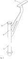
- der herausnehmbar gestaltete trennbare Teil der Saatgutleitung in vergrößertem Maßstab und in perspektivischer Darstellung,
- Fig.6
- ein weiteres Einzelkornsäaggregat einer als Einzelkornsämaschine ausgebildeten Sämaschine in Prinzipdarstellung und in Seitenansicht, wobei die Saatgutleitung an der Trennstelle geschlossen ist,
- Fig.7
- der in einem größeren Maßstab dargestellte zu trennende Saatleitungsbereich nach
Fig.6 in Seitenansicht, - Fig.8
- das Einzelkornsäaggregat in der gleichen Darstellungsweise wie
Fig.6 , wobei jedoch die Saatgutleitung an der Trennstelle geöffnet ist, - Fig.9
- der in einem größeren Maßstab dargestellte zu trennende Saatleitungsbereich nach
Fig.7 in perspektivischer Darstellung, - Fig.10
- der in einem größeren Maßstab dargestellte zu trennende Saatleitungsbereich nach
Fig.9 in Seitenansicht und - Fig.11
- die Saatgutleitung mit dem herausnehmbar gestalteten trennbaren Teil der Saatgutleitung im Schnitt A - A.
- Das Einzelkornsäaggregat 1 weist einen Rahmen 2 auf, der in bekannter und daher nicht dargestellter Weise an einem Querbalken der als Einzelkornsämaschine ausgebildete Sämaschine zu befestigen ist. In bekannter Weise sind mehrere Einzelkornsäaggregate 1 beabstandet nebeneinander an dem Querbalken angeordnet. An dem Rahmen 2 des Einzelkornsäaggregates 1 ist die Schareinheit 3, die Vereinzelungsvorrichtung 4 und der Saatgutbehälter 5 angeordnet. Zwischen der Vereinzelungsvorrichtung 4 und der als Schareinheit 3 ausgebildeten Abgabe- und/oder Ablageeinrichtung ist die trennbar ausgebildete Saatgutleitung 6 angeordnet. Die Saatgutleitung 6 weist die Trennstelle 7 mit dem werkzeuglos zu öffnenden und wieder zu verschließenden Verbindungselement 8 auf.
- Das Verbindungselement 7 weist das miteinander zusammenwirkende konusartige Vaterteil 9 und das konusartige Mutterteil 10 auf. Unterhalb von dem Verbindungselement 7 ist in der Saatgutleitung 6 das rohrförmig ausgebildete Federelement 11 angeordnet. Dieses Federelement 11 ist als Gummifeder und gummifederartiges Rohrelement ausgebildet und bildet einen Teil der Saatgutleitung 6. Im oberen Bereich 12 des unteren Teiles 13 der trennbaren Saatgutleitung 6 ist das als Handhebel ausgebildete Handbetätigungselement 14 angeordnet. Im Ausführungsbeispiel befindet sich das konusartige Vaterteil 9 des Verbindungselementes 7 am unteren Ende des oberen trennbaren Teiles der Saatgutleitung 6, während das Mutterteil 10 des Verbindungselementes 7 am oberen Ende des trennbaren Teiles der Saatgutleitung 6 befindet. Das trennbare Teil 13 der Saatgutleitung 6 kann herausnehmbar in der Saatgutleitung 6 angeordnet sein.
- Das Federelement 11 weist in geschlossener Position der Saatgutleitung 6, wie in den
Fig. 1 und 2 dargestellt, eine Vorspannung auf, so dass das Federelement 11 das trennbare Teil 13 der Saatgutleitung 6 in Richtung des Verbindungselementes 7 drückt. Somit wird ausschließlich durch die Vorspannung des Federelementes 11 das Verbindungselement 7 der Saatgutleitung 6 in Schließposition gehalten. - Die Funktionsweise, um die Saatgutleitung 6 einerseits aus der Verbindungs- bzw. Schließstellung und in die Öffnungsstellung und andererseits umgedreht zu bringen, ist folgende:
- Wenn zum Beispiel aufgrund einer Verstopfung der Saatgutleitung 6 oder zur Reinigung der Saatgutleitung 6 die Saatgutleitung 6 im Bereich der Trennstelle 7 geöffnet werden muss, so kann alleine durch das Drücken auf das Handbetätigungselement 14 in Pfeilrichtung 15 der trennbare Teil 13 der Saatgutleitung 6 werkzeuglos nach unten gedrückt werden, umso das Verbindungselement 8 zu öffnen, den trennbaren Teil 13 der Saatgutleitung 6 zur Seite zu schwenken, wie dies die
Fig.3 und 4 zeigen. Auch ist, wenn die Stelle im Bereich des Federelementes 11 so ausgestaltet ist, der trennbare Teil 13 der Saatgutleitung 6 ganz herauszunehmen. - Wenn die Verstopfung der Saatgutleitung 6 beseitigt oder diese gereinigt ist, so lässt sich das trennbare Teil 13 der Saatgutleitung 6 wieder in seine geschlossene Position verschwenken. Wenn das trennbare Teil 13 der Saatgutleitung 6 soweit verschwenkt ist, dass sich das Mutterteil 10 in der Nähe des Vaterteiles 9 befindet, wird durch Drücken auf das Handbetätigungselement 14 in Pfeilrichtung 15 der trennbare Teil 13 der Saatgutleitung 6 nach unten gedrückt und weiter soweit verschwenkt, bis sich das Mutterteil 10 direkt unterhalb des Vaterteiles 9 befindet. In dieser Position wird die Druckkraft von dem Handbetätigungselement 14 weggenommen, so dass das Vaterteil 9 in das Mutterteil 10 ein schnappt. Allein hierdurch wird die Verbindung der Saatgutleitung 6 im Bereich des Verbindungselementes 8 wiederhergestellt.
- Somit kann durch die erfindungsgemäße Ausgestaltung auf ein zusätzliches bajonett- oder schraubenartiges Verriegelungselement im Bereich der Verbindungsstelle 7 verzichtet werden.
- Das Einzelkornsäaggregat 101 gemäß
Fig. 6 weist einen Rahmen 102 auf, der in bekannter und daher nicht dargestellter Weise an einem Querbalken der als Einzelkornsämaschine ausgebildeten Sämaschine zu befestigen ist. In bekannter Weise sind mehrere Einzelkornsäaggregate 101 beabstandet nebeneinander an einem nicht dargestellten Querbalken angeordnet. An dem Rahmen 102 des Einzelkornsäaggregates 101 ist die Schareinheit 103, die Vereinzelungsvorrichtung 104 und der Saatgutbehälter 105 angeordnet. Zwischen der Vereinzelungsvorrichtung 104 und der als Schareinheit 103 ausgebildeten Abgabe- und/oder Ablageeinrichtung ist die trennbar ausgebildete Saatgutleitung 106 angeordnet. Die Saatgutleitung 106 weist die beiden Trennstellen 107 und 108 mit der dazwischen einzusetzenden und entfernbaren Zwischenleitung 109 auf. - Die Zwischenleitung 109 und die Saatgutleitung 106 weisen im Bereich der Trennstellen 107 und 108 miteinander zusammenwirkende konusartige Vaterteile 110 und Mutterteile 111 auf. Im Bereich der unteren Trennstelle 107 ist in der Saatgutleitung 106 das rohrförmig ausgebildete Federelement 120 angeordnet. Dieses Federelement 120 ist als Gummifeder und gummifederartiges Rohrelement ausgebildet und umschließt die Zwischenleitung 109 in deren unterem Bereich. Das Federelement 120 kann auch als Schaumstoffelement ausgebildet sein.
- Somit ist die Saatgutleitung 106 über die beiden Trennstellen 107 und 108 in einen ersten und einen zweiten Bereich teilt. Zwischen den zwei Trennstellen 107 und 108 der Saatgutleitung 106 ist die Zwischenleitung 109 der Saatgutleitung 106, die den ersten und zweiten Bereich der Saatgutleitung 106 überbrückend verbindet, angeordnet ist. Die Trennstellen 107 und 108 sind, wie vor beschrieben, werkzeuglos zu öffnende und wieder zu verschließende, als konusartig zusammenwirkende Vater- 110 und Mutterteile 111 ausgebildet. Der unteren Trennstelle 7 und den als Vater- 110 und Mutterteile 111 ausgebildeten Verbindungselementen zwischen der Saatgutleitung 106 und der Zwischenleitung 109 ist das in Verbindungs- und Schließstellung haltende Federelement 120 zugeordnet.
- Hierdurch lässt sich die Saatgutleitung 106 an den vorgesehenen Trendstellen 107 und 108 in einfacher Weise öffnen, indem die Zwischenleitung 109 herauszunehmen ist. Über das Federelement 120 wird das Zwischenelement 109 in seiner Verbindungs- und Schließstellung gehalten. Weiterhin wird ein sicherer Halt und Zentrierung der Zwischenleitung 109 in der Saatgutleitung 106 durch die konusartig ausgebildeten und zusammenwirkenden Vater- 110 und Mutterteile 110 in Verbindung mit dem Federelement 120 gewährleistet. Gleichzeitig ergibt sich eine gute Abdichtung der Zwischenleitung 109 zu dem übrigen Bereichen der Saatgutleitung 106.
- So ist auch ein einfacher Halt der Zwischenleitung 109 in der Saatgutleitung 106 sowie die Möglichkeit einer einfachen Demontage und Herausnahme der Zwischenleitung 109 an den Trennstellen 107 und 108 der Saatgutleitung 106 gewährleistet. Hierbei halten die konusartig ausgestalteten Verbindungselemente 110 und 111 ausschließlich durch das Federelement 120 die Zwischenleitung 109 in der Saatgutleitung 106 in Verbindungs- und Schließstellung.
- Das Federelement 120 ist der Zwischenleitung 109 zugeordnet und auf der der Saatgutleitung 106 zugewandten Seite konisch ausgebildet. Hierdurch ergibt sich vorteilhafte Zuordnung des Federelementes 120 mit einer guten Abdichtung zwischen der Zwischenleitung 109 und der Saautgutleitung 106 in dem Bereich der Trennstellen 107 und 108.
- Um beispielsweise Verstopfungen in der Saatgutleitung 106 in einfacher Weise zu beseitigen lässt sich die Zwischenleitung 109 aus der Saatgutleitung 106 herausnehmen.
- Das Federelement 120 weist in geschlossener Position der Saatgutleitung 6, wie in den
Fig. 6 ,7 , und9 bis 11 dargestellt, eine Vorspannung auf, so dass das Federelement 120 das trennbare Teil 109 der Saatgutleitung 106 zwischen den Trennstellen 107 und 108 der Saatgutleitung hält. Somit wird ausschließlich durch die Vorspannung des Federelementes 120 das Verbindungselement 109 der Saatgutleitung 106 in Schließposition gehalten. - Die Funktionsweise, um die Zwischenleitung 109 der Saatgutleitung 106 einerseits aus der Verbindungs- bzw. Schließstellung und in die Öffnungsstellung und andererseits umgedreht zu bringen, ist folgende:
- Wenn zum Beispiel aufgrund einer Verstopfung der Saatgutleitung 106 oder zur Reinigung der Saatgutleitung 6 die Saatgutleitung 106 im Bereich der Trennstellen 107 und 108 geöffnet werden muss, so kann alleine durch das Drücken der Zwischenleitung 109 nach unten gegen die Federkraft des Federelementes 120 die Saatgutleitung 106 werkzeuglos nach unten gedrückt werden, umso die Saatgutleitung 106 zu öffnen, die heraustrennbare Zwischenleitung 109 der Saatgutleitung 106 zur Seite zu schwenken, wie dies die
Fig.8 zeigt, und anschließend heraus zu nehmen. - Wenn die Verstopfung der Saatgutleitung 106 beseitigt oder diese gereinigt ist, so lässt sich die Zwischenleitung 109 der Saatgutleitung 106 wieder in seine geschlossene Position zwischen den Trennstellen 107 und 108 wieder einsetzen, so dass die Verbindung der Saatgutleitung 106 im Bereich zwischen den Trennstellen 107 und 108 wiederhergestellt ist.
- Somit kann durch die erfindungsgemäße Ausgestaltung auf ein zusätzliches bajonett- oder schraubenartiges Verriegelungselement im Bereich der Zwischenleitung 109 im Bereich der Trennstellen 107 und 108 verzichtet werden.
Claims (15)
- Saatgutleitung (6) für eine Sämaschine, insbesondere Einzelkornsämaschine, die zwischen einer Dosiervorrichtung, wie eine Vereinzelungsvorrichtung (4) angeordnet ist, und einer Abgabe- und/oder Ablageeinrichtung (3) angeordnet ist, dadurch gekennzeichnet, dass die Saatgutleitung (6) zumindest eine Trennstelle (7) mit werkzeuglos zu öffnenden und wieder zu verschließenden Verbindungselement (8) aufweist.
- Saatgutleitung nach Anspruch 1, dadurch gekennzeichnet, dass der Saatgutleitung (6) ein das Verbindungselement (8) in Verbindungs- und Schließstellung haltendes Federelement (11) zugeordnet ist.
- Saatgutleitung nach zumindest einem der vorstehenden Ansprüche, dadurch gekennzeichnet, dass das Verbindungselement (8) als konusartiges zusammenwirkendes Vater- (9) und Mutterteil (10) ausgebildet ist.
- Saatgutleitung nach zumindest einem der vorstehenden Ansprüche, dadurch gekennzeichnet, dass das konusartige Verbindungselement (8) ausschließlich durch das Federelement (11) in Verbindungs- und Schließstellung gehalten wird.
- Saatgutleitung nach zumindest einem der vorstehenden Ansprüche, dadurch gekennzeichnet, dass das Federelement (11) als Bestandteil der Saatgutleitung (6)ausgebildet ist.
- Saatgutleitung nach zumindest einem der vorstehenden Ansprüche, dadurch gekennzeichnet, dass das Federelement rohrförmig (11) ausgebildet ist.
- Saatgutleitung nach zumindest einem der vorstehenden Ansprüche, dadurch gekennzeichnet, dass das Federelement (11) als Gummifeder und/oder gummifederartiges Rohrelement ausgebildet ist.
- Saatgutleitung nach zumindest einem der vorstehenden Ansprüche, dadurch gekennzeichnet, dass an dem trennbaren Teil (13) der Saatgutleitung (6) ein Handbetätigungselement (14) angeordnet ist.
- Saatgutleitung nach zumindest einem der vorstehenden Ansprüche, dadurch gekennzeichnet, dass der trennbare Teil (13) der Saatgutleitung (6) herausnehmbar angeordnet ist.
- Saatgutleitung für eine Sämaschine, insbesondere Einzelkornsämaschine, insbesondere nach Anspruch 1, die zwischen einer Dosiervorrichtung (104), wie einer Vereinzelungsvorrichtung angeordnet ist, und einer Abgabe- und/oder Ablageeinrichtung (103) angeordnet ist, dadurch gekennzeichnet, dass die Saatgutleitung (106) zumindest eine, vorzugsweise zumindest zwei Trennstellen (107 und 108), die Saatgutleitung (106) in einen ersten und einen zweiten Bereich teilt, aufweist, dass zwischen den zwei Trennstellen (107 und 108) der Saatgutleitung (106) eine Zwischenleitung (109) der Saatgutleitung (106), die den ersten und zweiten Bereich der Saatgutleitung (106) überbrückend verbindet, angeordnet ist, dass den Trennstellen (107 und 108) werkzeuglos zu öffnende und wieder zu verschließende Verbindungselemente (110 und 111) zwischen den Bereichen der Saatgutleitung (106) und der Zwischenleitung (109) zugeordnet sind, dass die Verbindungselemente (110 und 111) im Bereich der Trennstellen (107 und 108) als konusartig zusammenwirkende Vater- (110) und Mutterteile (111) ausgebildet sind, dass zumindest einem der Verbindungselemente (110 und 111) ein die Saatgutleitungen (106) und die Zwischenleitung (109) in Verbindungs- und Schließstellung haltendes Federelement (112) zugeordnet ist.
- Saatgutleitung (106) nach Anspruch10, dadurch gekennzeichnet, dass die konusartig ausgestalteten Verbindungselemente (110 und 111) ausschließlich durch das Federelement (112) in Verbindungs- und Schließstellung gehalten werden.
- Saatgutleitung (106) nach zumindest einem der vorstehenden Ansprüchen 10 und/oder 11, dadurch gekennzeichnet, dass das Federelement (112) der Zwischenleitung (109) zugeordnet und auf der der Saatgutleitung (106) zugewandten Seite konisch ausgebildet ist.
- Saatgutleitung (106) nach zumindest einem der vorstehenden Ansprüchen 10 bis 12, dadurch gekennzeichnet, dass das Federelement (112) rohrförmig ausgebildet ist und die Zwischenleitung (109) umschließt.
- Saatgutleitung (106) nach zumindest einem der vorstehenden Ansprüchen 10 bis 13, dadurch gekennzeichnet, dass das Federelement (112) als Gummifeder, Schaumstoffelement und/oder gummifederartiges Rohrelement ausgebildet ist.
- Saatgutleitung (106) nach zumindest einem der vorstehenden Ansprüchen 10 bis 14, dadurch gekennzeichnet, dass die Zwischenleitung (109) in der Saatgutleitung (106) herausnehmbar angeordnet ist.
Priority Applications (1)
| Application Number | Priority Date | Filing Date | Title |
|---|---|---|---|
| PL17401029T PL3228168T3 (pl) | 2016-04-05 | 2017-03-31 | Przewód materiału siewnego dla siewnika |
Applications Claiming Priority (2)
| Application Number | Priority Date | Filing Date | Title |
|---|---|---|---|
| DE102016106143.3A DE102016106143A1 (de) | 2016-04-05 | 2016-04-05 | Saatgutleitung für eine Sämaschine |
| DE102016123196.7A DE102016123196A1 (de) | 2016-12-01 | 2016-12-01 | Saatgutleitung für eine Sämaschine |
Publications (2)
| Publication Number | Publication Date |
|---|---|
| EP3228168A1 true EP3228168A1 (de) | 2017-10-11 |
| EP3228168B1 EP3228168B1 (de) | 2020-01-29 |
Family
ID=58606239
Family Applications (1)
| Application Number | Title | Priority Date | Filing Date |
|---|---|---|---|
| EP17401029.8A Active EP3228168B1 (de) | 2016-04-05 | 2017-03-31 | Saatgutleitung für eine sämaschine |
Country Status (3)
| Country | Link |
|---|---|
| EP (1) | EP3228168B1 (de) |
| HU (1) | HUE048553T2 (de) |
| PL (1) | PL3228168T3 (de) |
Cited By (1)
| Publication number | Priority date | Publication date | Assignee | Title |
|---|---|---|---|---|
| RU214660U1 (ru) * | 2022-09-26 | 2022-11-09 | Федеральное государственное бюджетное образовательное учреждение высшего образования "Национальный исследовательский Мордовский государственный университет им. Н.П. Огарёва" | Комбинированный сошник |
Citations (6)
| Publication number | Priority date | Publication date | Assignee | Title |
|---|---|---|---|---|
| US675450A (en) * | 1901-03-21 | 1901-06-04 | William H Stevens | Feed-tube for grain-drills. |
| US2428679A (en) * | 1945-02-23 | 1947-10-07 | Deere & Co | Flexible chute for planters |
| DE826523C (de) * | 1949-05-05 | 1952-01-03 | Hans Glas G M B H Isaria Masch | Saatrohr fuer Saemaschinen |
| US3099373A (en) * | 1961-03-13 | 1963-07-30 | Ebenhard S Gandrud | Flexible feed tube with bail fastening said tube to a discharge spout |
| EP1262705A1 (de) * | 2001-03-20 | 2002-12-04 | Deere & Company | Kupplung für eine Saatgut führende Leitung einer landwirtschaftlichen Sämaschine |
| DE60310281T2 (de) * | 2002-02-20 | 2007-07-05 | Kuhn S.A., Zabern/Saverne | Sameneinführvorrichtung |
-
2017
- 2017-03-31 EP EP17401029.8A patent/EP3228168B1/de active Active
- 2017-03-31 PL PL17401029T patent/PL3228168T3/pl unknown
- 2017-03-31 HU HUE17401029A patent/HUE048553T2/hu unknown
Patent Citations (6)
| Publication number | Priority date | Publication date | Assignee | Title |
|---|---|---|---|---|
| US675450A (en) * | 1901-03-21 | 1901-06-04 | William H Stevens | Feed-tube for grain-drills. |
| US2428679A (en) * | 1945-02-23 | 1947-10-07 | Deere & Co | Flexible chute for planters |
| DE826523C (de) * | 1949-05-05 | 1952-01-03 | Hans Glas G M B H Isaria Masch | Saatrohr fuer Saemaschinen |
| US3099373A (en) * | 1961-03-13 | 1963-07-30 | Ebenhard S Gandrud | Flexible feed tube with bail fastening said tube to a discharge spout |
| EP1262705A1 (de) * | 2001-03-20 | 2002-12-04 | Deere & Company | Kupplung für eine Saatgut führende Leitung einer landwirtschaftlichen Sämaschine |
| DE60310281T2 (de) * | 2002-02-20 | 2007-07-05 | Kuhn S.A., Zabern/Saverne | Sameneinführvorrichtung |
Cited By (1)
| Publication number | Priority date | Publication date | Assignee | Title |
|---|---|---|---|---|
| RU214660U1 (ru) * | 2022-09-26 | 2022-11-09 | Федеральное государственное бюджетное образовательное учреждение высшего образования "Национальный исследовательский Мордовский государственный университет им. Н.П. Огарёва" | Комбинированный сошник |
Also Published As
| Publication number | Publication date |
|---|---|
| EP3228168B1 (de) | 2020-01-29 |
| HUE048553T2 (hu) | 2020-07-28 |
| PL3228168T3 (pl) | 2020-06-15 |
Similar Documents
| Publication | Publication Date | Title |
|---|---|---|
| DE4102209C2 (de) | Ausflußvorrichtung für sanitäre Armaturen | |
| EP3181245B1 (de) | Düsenanordnung für fliessfähige substanzen | |
| EP1570716B1 (de) | Landwirtschaftliche Dossiervorrichtung | |
| DE102010002200A1 (de) | Kalibriervorrichtung | |
| DE102016118256B3 (de) | Reinigungssystem zur Fußbodenreinigung | |
| DE102007034997A1 (de) | Landwirtschaftliche Verteilvorrichtung | |
| EP3191651A1 (de) | Sanitäre auslaufarmatur | |
| EP2832202A1 (de) | Sämaschine | |
| DE3723636C2 (de) | Mähdrescher | |
| DE102008021935B4 (de) | Schneckenpresse | |
| DE1949926B2 (de) | Drillmaschine oder duengerstreuer mit dosiervorrichtungen | |
| EP3610714B1 (de) | Einzelkornsäaggregat | |
| EP3228168B1 (de) | Saatgutleitung für eine sämaschine | |
| DE102016123196A1 (de) | Saatgutleitung für eine Sämaschine | |
| WO2020198773A1 (de) | Fruchtpresse | |
| DE102016106143A1 (de) | Saatgutleitung für eine Sämaschine | |
| EP3228167B1 (de) | Säschar | |
| DE619492C (de) | Spritzduesenbefestigung an Flaschenwaschmaschinen | |
| DE3330156C1 (de) | Auslaufarmatur für Waschbecken und dergleichen | |
| EP3006636B1 (de) | Wandablauf mit Pumpe | |
| DE102016122552A1 (de) | Landwirtschaftliche Verteilmaschine mit Rühreinrichtung | |
| EP2481856A1 (de) | Füllventileinheit | |
| DE102017123632B4 (de) | Kontinuierlich arbeitende Teigknetvorrichtung | |
| EP3278647B1 (de) | Landwirtschaftliche sämaschine mit geteilter säwelle | |
| WO2011006869A1 (de) | Kontaminationsfreien probenehmer |
Legal Events
| Date | Code | Title | Description |
|---|---|---|---|
| PUAI | Public reference made under article 153(3) epc to a published international application that has entered the european phase |
Free format text: ORIGINAL CODE: 0009012 |
|
| STAA | Information on the status of an ep patent application or granted ep patent |
Free format text: STATUS: THE APPLICATION HAS BEEN PUBLISHED |
|
| AK | Designated contracting states |
Kind code of ref document: A1 Designated state(s): AL AT BE BG CH CY CZ DE DK EE ES FI FR GB GR HR HU IE IS IT LI LT LU LV MC MK MT NL NO PL PT RO RS SE SI SK SM TR |
|
| AX | Request for extension of the european patent |
Extension state: BA ME |
|
| STAA | Information on the status of an ep patent application or granted ep patent |
Free format text: STATUS: REQUEST FOR EXAMINATION WAS MADE |
|
| 17P | Request for examination filed |
Effective date: 20180409 |
|
| RBV | Designated contracting states (corrected) |
Designated state(s): AL AT BE BG CH CY CZ DE DK EE ES FI FR GB GR HR HU IE IS IT LI LT LU LV MC MK MT NL NO PL PT RO RS SE SI SK SM TR |
|
| GRAP | Despatch of communication of intention to grant a patent |
Free format text: ORIGINAL CODE: EPIDOSNIGR1 |
|
| STAA | Information on the status of an ep patent application or granted ep patent |
Free format text: STATUS: GRANT OF PATENT IS INTENDED |
|
| INTG | Intention to grant announced |
Effective date: 20191029 |
|
| GRAS | Grant fee paid |
Free format text: ORIGINAL CODE: EPIDOSNIGR3 |
|
| GRAA | (expected) grant |
Free format text: ORIGINAL CODE: 0009210 |
|
| STAA | Information on the status of an ep patent application or granted ep patent |
Free format text: STATUS: THE PATENT HAS BEEN GRANTED |
|
| AK | Designated contracting states |
Kind code of ref document: B1 Designated state(s): AL AT BE BG CH CY CZ DE DK EE ES FI FR GB GR HR HU IE IS IT LI LT LU LV MC MK MT NL NO PL PT RO RS SE SI SK SM TR |
|
| REG | Reference to a national code |
Ref country code: GB Ref legal event code: FG4D Free format text: NOT ENGLISH |
|
| REG | Reference to a national code |
Ref country code: CH Ref legal event code: EP |
|
| REG | Reference to a national code |
Ref country code: AT Ref legal event code: REF Ref document number: 1227802 Country of ref document: AT Kind code of ref document: T Effective date: 20200215 |
|
| REG | Reference to a national code |
Ref country code: IE Ref legal event code: FG4D Free format text: LANGUAGE OF EP DOCUMENT: GERMAN |
|
| REG | Reference to a national code |
Ref country code: DE Ref legal event code: R096 Ref document number: 502017003619 Country of ref document: DE |
|
| REG | Reference to a national code |
Ref country code: RO Ref legal event code: EPE |
|
| REG | Reference to a national code |
Ref country code: SE Ref legal event code: TRGR |
|
| REG | Reference to a national code |
Ref country code: NL Ref legal event code: MP Effective date: 20200129 |
|
| REG | Reference to a national code |
Ref country code: HU Ref legal event code: AG4A Ref document number: E048553 Country of ref document: HU |
|
| PG25 | Lapsed in a contracting state [announced via postgrant information from national office to epo] |
Ref country code: FI Free format text: LAPSE BECAUSE OF FAILURE TO SUBMIT A TRANSLATION OF THE DESCRIPTION OR TO PAY THE FEE WITHIN THE PRESCRIBED TIME-LIMIT Effective date: 20200129 Ref country code: RS Free format text: LAPSE BECAUSE OF FAILURE TO SUBMIT A TRANSLATION OF THE DESCRIPTION OR TO PAY THE FEE WITHIN THE PRESCRIBED TIME-LIMIT Effective date: 20200129 Ref country code: PT Free format text: LAPSE BECAUSE OF FAILURE TO SUBMIT A TRANSLATION OF THE DESCRIPTION OR TO PAY THE FEE WITHIN THE PRESCRIBED TIME-LIMIT Effective date: 20200621 Ref country code: NO Free format text: LAPSE BECAUSE OF FAILURE TO SUBMIT A TRANSLATION OF THE DESCRIPTION OR TO PAY THE FEE WITHIN THE PRESCRIBED TIME-LIMIT Effective date: 20200429 |
|
| REG | Reference to a national code |
Ref country code: LT Ref legal event code: MG4D |
|
| PG25 | Lapsed in a contracting state [announced via postgrant information from national office to epo] |
Ref country code: GR Free format text: LAPSE BECAUSE OF FAILURE TO SUBMIT A TRANSLATION OF THE DESCRIPTION OR TO PAY THE FEE WITHIN THE PRESCRIBED TIME-LIMIT Effective date: 20200430 Ref country code: BG Free format text: LAPSE BECAUSE OF FAILURE TO SUBMIT A TRANSLATION OF THE DESCRIPTION OR TO PAY THE FEE WITHIN THE PRESCRIBED TIME-LIMIT Effective date: 20200429 Ref country code: IS Free format text: LAPSE BECAUSE OF FAILURE TO SUBMIT A TRANSLATION OF THE DESCRIPTION OR TO PAY THE FEE WITHIN THE PRESCRIBED TIME-LIMIT Effective date: 20200529 Ref country code: HR Free format text: LAPSE BECAUSE OF FAILURE TO SUBMIT A TRANSLATION OF THE DESCRIPTION OR TO PAY THE FEE WITHIN THE PRESCRIBED TIME-LIMIT Effective date: 20200129 Ref country code: LV Free format text: LAPSE BECAUSE OF FAILURE TO SUBMIT A TRANSLATION OF THE DESCRIPTION OR TO PAY THE FEE WITHIN THE PRESCRIBED TIME-LIMIT Effective date: 20200129 |
|
| PG25 | Lapsed in a contracting state [announced via postgrant information from national office to epo] |
Ref country code: NL Free format text: LAPSE BECAUSE OF FAILURE TO SUBMIT A TRANSLATION OF THE DESCRIPTION OR TO PAY THE FEE WITHIN THE PRESCRIBED TIME-LIMIT Effective date: 20200129 |
|
| PG25 | Lapsed in a contracting state [announced via postgrant information from national office to epo] |
Ref country code: EE Free format text: LAPSE BECAUSE OF FAILURE TO SUBMIT A TRANSLATION OF THE DESCRIPTION OR TO PAY THE FEE WITHIN THE PRESCRIBED TIME-LIMIT Effective date: 20200129 Ref country code: SM Free format text: LAPSE BECAUSE OF FAILURE TO SUBMIT A TRANSLATION OF THE DESCRIPTION OR TO PAY THE FEE WITHIN THE PRESCRIBED TIME-LIMIT Effective date: 20200129 Ref country code: LT Free format text: LAPSE BECAUSE OF FAILURE TO SUBMIT A TRANSLATION OF THE DESCRIPTION OR TO PAY THE FEE WITHIN THE PRESCRIBED TIME-LIMIT Effective date: 20200129 Ref country code: SK Free format text: LAPSE BECAUSE OF FAILURE TO SUBMIT A TRANSLATION OF THE DESCRIPTION OR TO PAY THE FEE WITHIN THE PRESCRIBED TIME-LIMIT Effective date: 20200129 Ref country code: DK Free format text: LAPSE BECAUSE OF FAILURE TO SUBMIT A TRANSLATION OF THE DESCRIPTION OR TO PAY THE FEE WITHIN THE PRESCRIBED TIME-LIMIT Effective date: 20200129 Ref country code: MC Free format text: LAPSE BECAUSE OF FAILURE TO SUBMIT A TRANSLATION OF THE DESCRIPTION OR TO PAY THE FEE WITHIN THE PRESCRIBED TIME-LIMIT Effective date: 20200129 Ref country code: ES Free format text: LAPSE BECAUSE OF FAILURE TO SUBMIT A TRANSLATION OF THE DESCRIPTION OR TO PAY THE FEE WITHIN THE PRESCRIBED TIME-LIMIT Effective date: 20200129 |
|
| REG | Reference to a national code |
Ref country code: CH Ref legal event code: PL Ref country code: DE Ref legal event code: R097 Ref document number: 502017003619 Country of ref document: DE |
|
| PLBE | No opposition filed within time limit |
Free format text: ORIGINAL CODE: 0009261 |
|
| STAA | Information on the status of an ep patent application or granted ep patent |
Free format text: STATUS: NO OPPOSITION FILED WITHIN TIME LIMIT |
|
| REG | Reference to a national code |
Ref country code: BE Ref legal event code: MM Effective date: 20200331 |
|
| PG25 | Lapsed in a contracting state [announced via postgrant information from national office to epo] |
Ref country code: LU Free format text: LAPSE BECAUSE OF NON-PAYMENT OF DUE FEES Effective date: 20200331 |
|
| 26N | No opposition filed |
Effective date: 20201030 |
|
| PG25 | Lapsed in a contracting state [announced via postgrant information from national office to epo] |
Ref country code: LI Free format text: LAPSE BECAUSE OF NON-PAYMENT OF DUE FEES Effective date: 20200331 Ref country code: IE Free format text: LAPSE BECAUSE OF NON-PAYMENT OF DUE FEES Effective date: 20200331 Ref country code: CH Free format text: LAPSE BECAUSE OF NON-PAYMENT OF DUE FEES Effective date: 20200331 |
|
| PG25 | Lapsed in a contracting state [announced via postgrant information from national office to epo] |
Ref country code: SI Free format text: LAPSE BECAUSE OF FAILURE TO SUBMIT A TRANSLATION OF THE DESCRIPTION OR TO PAY THE FEE WITHIN THE PRESCRIBED TIME-LIMIT Effective date: 20200129 Ref country code: BE Free format text: LAPSE BECAUSE OF NON-PAYMENT OF DUE FEES Effective date: 20200331 |
|
| REG | Reference to a national code |
Ref country code: DE Ref legal event code: R081 Ref document number: 502017003619 Country of ref document: DE Owner name: AMAZONEN-WERKE H. DREYER SE & CO. KG, DE Free format text: FORMER OWNER: AMAZONEN-WERKE H. DREYER GMBH & CO. KG, 49205 HASBERGEN, DE |
|
| GBPC | Gb: european patent ceased through non-payment of renewal fee |
Effective date: 20210331 |
|
| PG25 | Lapsed in a contracting state [announced via postgrant information from national office to epo] |
Ref country code: GB Free format text: LAPSE BECAUSE OF NON-PAYMENT OF DUE FEES Effective date: 20210331 |
|
| PG25 | Lapsed in a contracting state [announced via postgrant information from national office to epo] |
Ref country code: TR Free format text: LAPSE BECAUSE OF FAILURE TO SUBMIT A TRANSLATION OF THE DESCRIPTION OR TO PAY THE FEE WITHIN THE PRESCRIBED TIME-LIMIT Effective date: 20200129 Ref country code: MT Free format text: LAPSE BECAUSE OF FAILURE TO SUBMIT A TRANSLATION OF THE DESCRIPTION OR TO PAY THE FEE WITHIN THE PRESCRIBED TIME-LIMIT Effective date: 20200129 Ref country code: CY Free format text: LAPSE BECAUSE OF FAILURE TO SUBMIT A TRANSLATION OF THE DESCRIPTION OR TO PAY THE FEE WITHIN THE PRESCRIBED TIME-LIMIT Effective date: 20200129 |
|
| PG25 | Lapsed in a contracting state [announced via postgrant information from national office to epo] |
Ref country code: MK Free format text: LAPSE BECAUSE OF FAILURE TO SUBMIT A TRANSLATION OF THE DESCRIPTION OR TO PAY THE FEE WITHIN THE PRESCRIBED TIME-LIMIT Effective date: 20200129 Ref country code: AL Free format text: LAPSE BECAUSE OF FAILURE TO SUBMIT A TRANSLATION OF THE DESCRIPTION OR TO PAY THE FEE WITHIN THE PRESCRIBED TIME-LIMIT Effective date: 20200129 |
|
| P01 | Opt-out of the competence of the unified patent court (upc) registered |
Effective date: 20230523 |
|
| PGFP | Annual fee paid to national office [announced via postgrant information from national office to epo] |
Ref country code: SE Payment date: 20260211 Year of fee payment: 10 |
|
| PGFP | Annual fee paid to national office [announced via postgrant information from national office to epo] |
Ref country code: DE Payment date: 20260102 Year of fee payment: 10 |
|
| PGFP | Annual fee paid to national office [announced via postgrant information from national office to epo] |
Ref country code: AT Payment date: 20260225 Year of fee payment: 10 |
|
| PGFP | Annual fee paid to national office [announced via postgrant information from national office to epo] |
Ref country code: RO Payment date: 20260226 Year of fee payment: 10 Ref country code: IT Payment date: 20260220 Year of fee payment: 10 |
|
| PGFP | Annual fee paid to national office [announced via postgrant information from national office to epo] |
Ref country code: HU Payment date: 20260303 Year of fee payment: 10 |
|
| PGFP | Annual fee paid to national office [announced via postgrant information from national office to epo] |
Ref country code: FR Payment date: 20260209 Year of fee payment: 10 |
|
| PGFP | Annual fee paid to national office [announced via postgrant information from national office to epo] |
Ref country code: CZ Payment date: 20260323 Year of fee payment: 10 |
|
| PGFP | Annual fee paid to national office [announced via postgrant information from national office to epo] |
Ref country code: PL Payment date: 20260113 Year of fee payment: 10 |