EP3227766B1 - Projection display unit and function control method - Google Patents
Projection display unit and function control method Download PDFInfo
- Publication number
- EP3227766B1 EP3227766B1 EP15767337.7A EP15767337A EP3227766B1 EP 3227766 B1 EP3227766 B1 EP 3227766B1 EP 15767337 A EP15767337 A EP 15767337A EP 3227766 B1 EP3227766 B1 EP 3227766B1
- Authority
- EP
- European Patent Office
- Prior art keywords
- projection
- region
- detection
- light
- optical system
- Prior art date
- Legal status (The legal status is an assumption and is not a legal conclusion. Google has not performed a legal analysis and makes no representation as to the accuracy of the status listed.)
- Active
Links
- 238000000034 method Methods 0.000 title claims description 11
- 238000001514 detection method Methods 0.000 claims description 112
- 230000003287 optical effect Effects 0.000 claims description 68
- 230000010287 polarization Effects 0.000 claims description 37
- 238000000926 separation method Methods 0.000 claims description 32
- 238000005286 illumination Methods 0.000 claims description 24
- 230000002093 peripheral effect Effects 0.000 claims description 19
- 230000001268 conjugating effect Effects 0.000 claims description 10
- 238000012545 processing Methods 0.000 description 11
- 210000001747 pupil Anatomy 0.000 description 10
- 238000010586 diagram Methods 0.000 description 8
- 230000000694 effects Effects 0.000 description 6
- 230000006872 improvement Effects 0.000 description 5
- 239000004973 liquid crystal related substance Substances 0.000 description 5
- 238000010079 rubber tapping Methods 0.000 description 4
- 230000008901 benefit Effects 0.000 description 3
- 238000013461 design Methods 0.000 description 3
- 230000002452 interceptive effect Effects 0.000 description 3
- 230000007257 malfunction Effects 0.000 description 3
- 230000001151 other effect Effects 0.000 description 3
- 230000009471 action Effects 0.000 description 2
- 238000005516 engineering process Methods 0.000 description 2
- 230000002708 enhancing effect Effects 0.000 description 2
- 230000009467 reduction Effects 0.000 description 2
- 239000004065 semiconductor Substances 0.000 description 2
- 230000004888 barrier function Effects 0.000 description 1
- 238000005452 bending Methods 0.000 description 1
- 230000000295 complement effect Effects 0.000 description 1
- 238000009792 diffusion process Methods 0.000 description 1
- 238000012423 maintenance Methods 0.000 description 1
- 229910044991 metal oxide Inorganic materials 0.000 description 1
- 150000004706 metal oxides Chemical class 0.000 description 1
- 238000012986 modification Methods 0.000 description 1
- 230000004048 modification Effects 0.000 description 1
- 230000008569 process Effects 0.000 description 1
- 238000002310 reflectometry Methods 0.000 description 1
- 229910052710 silicon Inorganic materials 0.000 description 1
- 239000010703 silicon Substances 0.000 description 1
- 238000005549 size reduction Methods 0.000 description 1
Images


Classifications
-
- G—PHYSICS
- G06—COMPUTING; CALCULATING OR COUNTING
- G06F—ELECTRIC DIGITAL DATA PROCESSING
- G06F3/00—Input arrangements for transferring data to be processed into a form capable of being handled by the computer; Output arrangements for transferring data from processing unit to output unit, e.g. interface arrangements
- G06F3/01—Input arrangements or combined input and output arrangements for interaction between user and computer
- G06F3/03—Arrangements for converting the position or the displacement of a member into a coded form
- G06F3/041—Digitisers, e.g. for touch screens or touch pads, characterised by the transducing means
- G06F3/042—Digitisers, e.g. for touch screens or touch pads, characterised by the transducing means by opto-electronic means
-
- G—PHYSICS
- G03—PHOTOGRAPHY; CINEMATOGRAPHY; ANALOGOUS TECHNIQUES USING WAVES OTHER THAN OPTICAL WAVES; ELECTROGRAPHY; HOLOGRAPHY
- G03B—APPARATUS OR ARRANGEMENTS FOR TAKING PHOTOGRAPHS OR FOR PROJECTING OR VIEWING THEM; APPARATUS OR ARRANGEMENTS EMPLOYING ANALOGOUS TECHNIQUES USING WAVES OTHER THAN OPTICAL WAVES; ACCESSORIES THEREFOR
- G03B17/00—Details of cameras or camera bodies; Accessories therefor
- G03B17/48—Details of cameras or camera bodies; Accessories therefor adapted for combination with other photographic or optical apparatus
- G03B17/54—Details of cameras or camera bodies; Accessories therefor adapted for combination with other photographic or optical apparatus with projector
-
- G—PHYSICS
- G06—COMPUTING; CALCULATING OR COUNTING
- G06F—ELECTRIC DIGITAL DATA PROCESSING
- G06F1/00—Details not covered by groups G06F3/00 - G06F13/00 and G06F21/00
- G06F1/16—Constructional details or arrangements
- G06F1/1613—Constructional details or arrangements for portable computers
- G06F1/1633—Constructional details or arrangements of portable computers not specific to the type of enclosures covered by groups G06F1/1615 - G06F1/1626
- G06F1/1637—Details related to the display arrangement, including those related to the mounting of the display in the housing
- G06F1/1639—Details related to the display arrangement, including those related to the mounting of the display in the housing the display being based on projection
-
- G—PHYSICS
- G06—COMPUTING; CALCULATING OR COUNTING
- G06F—ELECTRIC DIGITAL DATA PROCESSING
- G06F3/00—Input arrangements for transferring data to be processed into a form capable of being handled by the computer; Output arrangements for transferring data from processing unit to output unit, e.g. interface arrangements
- G06F3/002—Specific input/output arrangements not covered by G06F3/01 - G06F3/16
- G06F3/005—Input arrangements through a video camera
-
- G—PHYSICS
- G06—COMPUTING; CALCULATING OR COUNTING
- G06F—ELECTRIC DIGITAL DATA PROCESSING
- G06F3/00—Input arrangements for transferring data to be processed into a form capable of being handled by the computer; Output arrangements for transferring data from processing unit to output unit, e.g. interface arrangements
- G06F3/01—Input arrangements or combined input and output arrangements for interaction between user and computer
- G06F3/017—Gesture based interaction, e.g. based on a set of recognized hand gestures
-
- G—PHYSICS
- G06—COMPUTING; CALCULATING OR COUNTING
- G06F—ELECTRIC DIGITAL DATA PROCESSING
- G06F3/00—Input arrangements for transferring data to be processed into a form capable of being handled by the computer; Output arrangements for transferring data from processing unit to output unit, e.g. interface arrangements
- G06F3/01—Input arrangements or combined input and output arrangements for interaction between user and computer
- G06F3/02—Input arrangements using manually operated switches, e.g. using keyboards or dials
- G06F3/0202—Constructional details or processes of manufacture of the input device
- G06F3/0219—Special purpose keyboards
-
- G—PHYSICS
- G06—COMPUTING; CALCULATING OR COUNTING
- G06F—ELECTRIC DIGITAL DATA PROCESSING
- G06F3/00—Input arrangements for transferring data to be processed into a form capable of being handled by the computer; Output arrangements for transferring data from processing unit to output unit, e.g. interface arrangements
- G06F3/01—Input arrangements or combined input and output arrangements for interaction between user and computer
- G06F3/03—Arrangements for converting the position or the displacement of a member into a coded form
- G06F3/041—Digitisers, e.g. for touch screens or touch pads, characterised by the transducing means
- G06F3/042—Digitisers, e.g. for touch screens or touch pads, characterised by the transducing means by opto-electronic means
- G06F3/0425—Digitisers, e.g. for touch screens or touch pads, characterised by the transducing means by opto-electronic means using a single imaging device like a video camera for tracking the absolute position of a single or a plurality of objects with respect to an imaged reference surface, e.g. video camera imaging a display or a projection screen, a table or a wall surface, on which a computer generated image is displayed or projected
-
- G—PHYSICS
- G06—COMPUTING; CALCULATING OR COUNTING
- G06F—ELECTRIC DIGITAL DATA PROCESSING
- G06F3/00—Input arrangements for transferring data to be processed into a form capable of being handled by the computer; Output arrangements for transferring data from processing unit to output unit, e.g. interface arrangements
- G06F3/01—Input arrangements or combined input and output arrangements for interaction between user and computer
- G06F3/048—Interaction techniques based on graphical user interfaces [GUI]
- G06F3/0481—Interaction techniques based on graphical user interfaces [GUI] based on specific properties of the displayed interaction object or a metaphor-based environment, e.g. interaction with desktop elements like windows or icons, or assisted by a cursor's changing behaviour or appearance
- G06F3/0482—Interaction with lists of selectable items, e.g. menus
-
- G—PHYSICS
- G06—COMPUTING; CALCULATING OR COUNTING
- G06F—ELECTRIC DIGITAL DATA PROCESSING
- G06F3/00—Input arrangements for transferring data to be processed into a form capable of being handled by the computer; Output arrangements for transferring data from processing unit to output unit, e.g. interface arrangements
- G06F3/01—Input arrangements or combined input and output arrangements for interaction between user and computer
- G06F3/048—Interaction techniques based on graphical user interfaces [GUI]
- G06F3/0487—Interaction techniques based on graphical user interfaces [GUI] using specific features provided by the input device, e.g. functions controlled by the rotation of a mouse with dual sensing arrangements, or of the nature of the input device, e.g. tap gestures based on pressure sensed by a digitiser
- G06F3/0488—Interaction techniques based on graphical user interfaces [GUI] using specific features provided by the input device, e.g. functions controlled by the rotation of a mouse with dual sensing arrangements, or of the nature of the input device, e.g. tap gestures based on pressure sensed by a digitiser using a touch-screen or digitiser, e.g. input of commands through traced gestures
- G06F3/04886—Interaction techniques based on graphical user interfaces [GUI] using specific features provided by the input device, e.g. functions controlled by the rotation of a mouse with dual sensing arrangements, or of the nature of the input device, e.g. tap gestures based on pressure sensed by a digitiser using a touch-screen or digitiser, e.g. input of commands through traced gestures by partitioning the display area of the touch-screen or the surface of the digitising tablet into independently controllable areas, e.g. virtual keyboards or menus
-
- G—PHYSICS
- G06—COMPUTING; CALCULATING OR COUNTING
- G06V—IMAGE OR VIDEO RECOGNITION OR UNDERSTANDING
- G06V40/00—Recognition of biometric, human-related or animal-related patterns in image or video data
- G06V40/20—Movements or behaviour, e.g. gesture recognition
- G06V40/28—Recognition of hand or arm movements, e.g. recognition of deaf sign language
-
- H—ELECTRICITY
- H04—ELECTRIC COMMUNICATION TECHNIQUE
- H04N—PICTORIAL COMMUNICATION, e.g. TELEVISION
- H04N9/00—Details of colour television systems
- H04N9/12—Picture reproducers
- H04N9/31—Projection devices for colour picture display, e.g. using electronic spatial light modulators [ESLM]
- H04N9/3141—Constructional details thereof
- H04N9/3173—Constructional details thereof wherein the projection device is specially adapted for enhanced portability
- H04N9/3176—Constructional details thereof wherein the projection device is specially adapted for enhanced portability wherein the projection device is incorporated in a camera
-
- H—ELECTRICITY
- H04—ELECTRIC COMMUNICATION TECHNIQUE
- H04N—PICTORIAL COMMUNICATION, e.g. TELEVISION
- H04N9/00—Details of colour television systems
- H04N9/12—Picture reproducers
- H04N9/31—Projection devices for colour picture display, e.g. using electronic spatial light modulators [ESLM]
- H04N9/3191—Testing thereof
- H04N9/3194—Testing thereof including sensor feedback
-
- G—PHYSICS
- G09—EDUCATION; CRYPTOGRAPHY; DISPLAY; ADVERTISING; SEALS
- G09G—ARRANGEMENTS OR CIRCUITS FOR CONTROL OF INDICATING DEVICES USING STATIC MEANS TO PRESENT VARIABLE INFORMATION
- G09G2340/00—Aspects of display data processing
- G09G2340/04—Changes in size, position or resolution of an image
- G09G2340/0464—Positioning
- G09G2340/0471—Vertical positioning
-
- G—PHYSICS
- G09—EDUCATION; CRYPTOGRAPHY; DISPLAY; ADVERTISING; SEALS
- G09G—ARRANGEMENTS OR CIRCUITS FOR CONTROL OF INDICATING DEVICES USING STATIC MEANS TO PRESENT VARIABLE INFORMATION
- G09G2340/00—Aspects of display data processing
- G09G2340/04—Changes in size, position or resolution of an image
- G09G2340/0464—Positioning
- G09G2340/0478—Horizontal positioning
-
- G—PHYSICS
- G09—EDUCATION; CRYPTOGRAPHY; DISPLAY; ADVERTISING; SEALS
- G09G—ARRANGEMENTS OR CIRCUITS FOR CONTROL OF INDICATING DEVICES USING STATIC MEANS TO PRESENT VARIABLE INFORMATION
- G09G2354/00—Aspects of interface with display user
-
- H—ELECTRICITY
- H04—ELECTRIC COMMUNICATION TECHNIQUE
- H04N—PICTORIAL COMMUNICATION, e.g. TELEVISION
- H04N9/00—Details of colour television systems
- H04N9/12—Picture reproducers
- H04N9/31—Projection devices for colour picture display, e.g. using electronic spatial light modulators [ESLM]
Definitions
- the present disclosure relates to a projection display unit having a detection function and a function control method using this projection display unit.
- a touch panel allows for page-turning and zooming in or out of an image displayed on a screen by an intuitive pointing operation.
- a display unit configured to perform display by projecting an image on a screen
- a projector projection display unit
- a projection display unit is known from US 2012/0313910 A1 .
- This document discloses a protection display unit comprising an image pickup unit configured to receive invisible light emitted by an invisible light emitter to generate a pickup image.
- US 2004/0141162A1 discloses a projection display unit including a light engine configured to project an image onto a display surface, an image sensor configure to capture a presentation image larger than the projected image, and a processor coupled to the image sensor that is configured to modify the projected image based on the captured image.
- EP 3 550 359 A1 discloses an optical module configured to separate first and second polarized components of incident light, a light valve configured to receive at least the first polarized component, and output at least a portion of the received light to the polarized-light separation device.
- US 2011/0241986 A1 relates to an interactive projection device including a projection optical system, a light source section configured to emit invisible light for detection of an input operation, a polarization separation device, and a detection optical system.
- image projection by a projection optical system and capturing of detected light by a detection optical system are performed with use of one projection lens, and a light valve configured to produce an image and an image pickup device configured to receive detected light are disposed in positions optically conjugating with each other.
- a light valve configured to produce an image and an image pickup device configured to receive detected light are disposed in positions optically conjugating with each other.
- the image pickup device is disposed in the position optically conjugating with the light valve, and light, based on the invisible light (a part of invisible light reflected by the object) enters the image pickup device through the projection lens and the polarization separation device; therefore, an image pickup signal, based on the invisible light is allowed to be obtained.
- An object in a peripheral region of the projection region is allowed to be detected, based on the image pickup signal, and a function, based on a specific input operation is allowed to be executed accordingly. Therefore, an input operation is possible not only in the projection region but also the peripheral region of the projection region, and flexibility of the input operation is enhanced. Thus, an improvement in operability by a user is possible.
- Embodiment An example of a projection display unit in which channel regions for detection of a specific input operation are provided in and out of a projection region
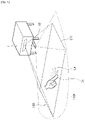
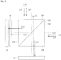
- Fig. 1 illustrates an appearance and a usage state of a projection display unit (a projection display unit 1) according to an embodiment of the present disclosure.
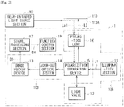
- Fig. 2 illustrates a function configuration of the projection display unit 1.
- the projection display unit 1 may be, for example, a projector (a so-called ultra short throw projector) configured to project an image in proximity thereto while being placed on a flat surface such as a top of a table (or while being mounted on a wall surface or the like).
- This projection display unit 1 also has a function of actively performing object detection in addition to image display.
- a user is allowed to perform a predetermined input operation by performing some operation such as touching a displayed image with his finger (an indicator 71) in a projection region S11 (a projectable region corresponding to a light valve size) where an image is projected.
- the projection display unit 1 includes an illumination section 11, a light valve 2, an image pickup device 13, a zoom-out optical system 14, a polarization separation device 15, a projection lens 16, a signal processing section 17, and a function control section 19.
- the illumination section 11, the light valve 12, and the projection lens 16 configure a projection optical system 10A
- the image pickup device 13 and the zoom-out optical system 14 configure a detection optical system 10B.
- driving of the illumination section 11, the light valve 12, the image pickup device 13, the signal processing section 17, and the function control section 19 may be controlled by a system control section (not illustrated) at a predetermined timing.
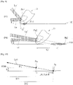
- a near-infrared light source section 40 is provided on a casing of the projection display unit 1.
- the near-infrared light source section 40 is a light source section configured to emit near-infrared light (NIR) as invisible light for detection, and is configured to emit near-infrared light along a plane in proximity to a projection surface 110.
- a near-infrared light barrier film (a detection light plane 110A) is formed in proximity to the projection surface 110 to cover the projection region S11.
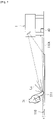
- the detection light plane 110A is formed in a plane at a predetermined height h, which is different from a height of an optical axis passing through the projection lens 16, from the projection surface 1110 (refer to Fig. 3 ).
- the detection light plane 110A may be formed, for example, with a thickness (a width in a height direction) of about 2 mm to about 3 mm in a position at the height h of about several mm to about several tens of mm to cover the projection region S11 in an in-plane direction.
- the projection surface 110 is flat; therefore, as long as a shielding object or the indicator 71 such as a finger and a pointer is not present, the detection light plane 110A is not blocked. In other words, no image appears on the image pickup device 13 that monitors the projection surface 110.
- near-infrared light of the detection light plane 110A is blocked by the finger or the like, and is diffused and reflected at a point where the near-infrared light of the detection light plane 110 is blocked.
- Light reflected by the finger or the like radiates in all directions, and a part of the reflected light is captured in an aperture of the projection lens 16. The part of the reflected light reaches the image pickup device 13 through the projection lens 16 and the polarization separation device 15.
- the light valve 12 configured to produce an image, and the image pickup device 13 are disposed in positions optically conjugated with each other; therefore, a bright spot diffusion point generated in a dot shape on the projection surface 110 forms an image on the image pickup device 13, and forms an image in a corresponding position on the projected image. Therefore, position detection of an object is possible.
- projected light passes in proximity to the projection surface 110, and a part of a body of a user who operates the projector is less likely to block the projected light; therefore, there is an advantage that a screen is easily seen when the user operates the projector.
- the near-infrared light source section 40 may be provided, for example, on a bottom of the casing of the projection display unit 1, as illustrated; however, the near-infrared light source section 40 may be or may not be disposed adjacent to the projection display unit 1. As long as the detection light plane 110A is allowed to be formed to cover the projection region S11, the detection light source 110 may be disposed in a position away from the projection display unit 1. Alternatively, the near-infrared light source section 40 may be disposed inside the casing (an enclosure) of the projection display unit 1. In this embodiment, the near-infrared light source section 40 is allowed to be disposed at a height relatively away from the projection surface 110 by optical design that will be described later, and is easily bundled integrally with the projection display unit 1 accordingly.
- the detection light plane 110A allows near-infrared light to be reflected (diffused and reflected) by the indicator 71, and then allows a part of the reflected light to be captured in the projection display unit 1 as detected light.
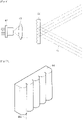
- the near-infrared light source section 40 may include, for example, a near-infrared laser 42, a collimator lens 43, and a cylinder array lens 44.
- the detection light plane 110A is formed of near-infrared light 41 emitted from the cylinder array lens 44.
- the cylinder array lens 44 is configured of an array of a plurality of convex cylinder lenses.
- the cylinder array lens 44 is disposed to allow a generatrix 44A of each cylinder lens to face a plane perpendicular to the projection surface 110.
- a cylinder array lens 45 configured of an array of a plurality of concave cylinder lenses may be used.
- the illumination section 11 is configured to emit illumination light L1 toward the light valve 12 through the polarization separation device 15. As long as the illumination section 11 emits visible light as the illumination light L1, the illumination section 11 is not specifically limited.
- the illumination section 11 may include, for example, a blue laser, a green laser, and a red laser (all of which are not illustrated).
- the light valve 12 may be a reflective liquid crystal device such as LCOS (Liquid Crystal On Silicon).
- the light valve 12 may be configured to modulate a first polarized component (for example, an s-polarized component Ls1 that will be described later) included in the illumination light L1, based on image data.
- a polarization state of light modulated by the light valve 12 is rotated, and thus the light is converted into a second polarized component (for example, a p-polarized component that will be described alter). This modulated light is emitted toward the projection lens 16 through the polarization separation device 15.
- black display is allowed to be performed by returning incident light (the s-polarized component Ls1) to the polarization separation device 15 without changing the polarization state thereof.
- a planar shape of an effective region (a rectangular shape A1 that will be described later) of the light valve 12 is rectangular.
- the projection lens 16 is configured to project, onto the projection surface 110, light (image light L2) having entered from the light valve 12 through the polarization separation device 15.
- the projection lens 16 may be, for example, an ultra short throw lens with a throw ratio of about 0.38 or less.
- the throw ratio is represented by L/H, where a distance from the projection lens 16 to the projection surface 110 is L and a width of the projection region S11 is H.
- detected light near-infrared light La1 enters this projection lens 16 from an opposite direction to a travel direction of modulated light.
- the detected light is captured through the projection lens 16 of the projection optical system 10A to be guided to the detection optical system 10B.
- a diameter of an image circle by the projection lens 16 is set within a predetermined range.
- the polarization separation device 15 is configured to separate incident light into the first polarized component (for example, an s-polarized component) and the second polarized component (for example, a p-polarized component) and emit the first and second polarized components in different directions from each other.
- This polarization separation device 15 may be configured of, for example, a polarizing beam splitter (PBS), and may be configured to selectively reflect the first polarized component (reflect the first polarized component on a polarization separation surface 150) and allow the second polarized component to selectively pass therethrough (pass through the polarization separation surface 150).
- PBS polarizing beam splitter
- the polarizing beam splitter is used as the polarization separation device 15 as an example; however, the polarization separation device 15 is not limited thereto, and may be configured of a wire grid.
- the wire grid has different characteristics from those of the polarizing beam splitter, and is allowed to selectively reflect the p-polarized component as the first polarized component of incident light and allow the s-polarized component of the incident light as the second polarized component to selectively pass therethrough.
- this polarization separation device 15 may have four optical surfaces (a first surface 15A, a second surface 15B, a third surface 15C, and a fourth surface 15D) and the polarization separation surface 150.
- the first surface 15A and the third surface 15C are disposed to face each other in one axis direction (a horizontal direction in the diagram), and the second surface 15B and the fourth surface 15D are disposed to face each other in one axis direction (a vertical direction in the diagram).
- the illumination light L1 enters the first surface 15A, and the light valve 12 is disposed to face the second surface 15B.
- the detection optical system 10B is disposed to face the third surface 15C, and the projection lens 15 is disposed to face the fourth surface 15D.
- FIG. 7 illustrates a configuration example of the polarization separation device 15.
- the polarization separation device 15 reflects the first polarization component (the s-polarized component Ls1) of the illumination light L1 having entered from the first surface 15A and emits the first polarization component from the second surface 15B.
- the polarization separation device 15 emits, from the third surface 15C, the second polarized component (a p-polarized component Lp1) of the illumination light L1.
- the polarization separation device 15 emits, from the fourth surface 15D, the second polarized component (a p-polarized component Lp2) of light having entered from the second surface 15B (modulated light from the light valve 12). Therefore, an image is projected by the projection optical system 10A.
- the polarization separation device 15 reflects the first polarized component (an s-polarized component Ls3) of light (the near-infrared light La1) having entered from the fourth surface 15D, and emits the first polarized component from the third surface 15C.
- Light, based on this s-polarized component Ls3 is received by the image pickup device 13.
- an image pickup signal DO is obtained by the image pickup device 13.
- the image pickup device 13 is disposed in a position optically conjugating with the light valve 12. More specifically, in a case where the light valve 12 is a reflective liquid crystal device, a display surface (a liquid crystal surface) where an image is produced of the light valve 12 and an image pickup surface of the image pickup device 13 are disposed to have an optically conjugating relationship therebetween.
- the image pickup device 13 may be configured of a solid-state image pickup device such as a CMOS (Complementary Metal-Oxide Semiconductor) or a CCD (Charge Coupled Device), and the planar shape of the effective region (a rectangular shape A3 that will be described later) is rectangular.
- the size of the image pickup device 13 is designed to allow a peripheral region of the projection region S11 to also serve as a light reception target.
- an example of the detection optical system 10B including this image pickup device 13 may be a detection optical system in which a visible light cut filter 17A, a bandpass filter 17B, a zoom-out optical system 14 (relay lens groups 14A and 14B), a polarizer 18, and the image pickup device 13 are arranged in order from a conjugate plane 50.
- the visible light cut filter 17A is configured to reduce a visible light component of incident light.
- this visible light cut filter 17A is provided, even if the polarizing beam splitter is used as the polarization separation device 15, a large amount of the illumination light L1 having entered the image pickup device 13 is allowed to be cut without turning off a light source of the illumination section 11. Therefore, nearly only detected light is allowed to enter the image pickup device 13, and an S/N ratio is allowed to be increased, thereby enhancing detection accuracy.
- the number of visible light cut filters is not limited to one, and may be two or more.
- the visible light cut filter 17A is disposed in a position between the conjugate plane 50 and the zoom-out optical system 14 in this case, the visible light cut filter 17A may be disposed in another position, for example, between the zoom-out optical system 14 and the image pickup device 13.
- the bandpass filter 17B is configured to allow a specific wavelength (near-infrared light) to selectively pass therethrough and to reduce other wavelengths.
- the polarizer 18 is an optical member configured to reduce the second polarized component included in the illumination light L1.
- the polarization separation device 15 as described above allows the second polarized component (for example, the p-polarized component) of the illumination light L1 to pass therethrough; therefore, this p-polarized component may enter the detection optical system 10B, thereby influencing an S/N ratio of an image pickup signal obtained in the image pickup device 13.
- the second polarized component for example, the p-polarized component included in the illumination light L1 is allowed to be cut, thereby enhancing the S/N ratio.
- the position of the polarizer 18 is not limited to the illustrated position between the zoom-out optical system 14 and the image pickup device 13, and the polarizer 18 may be disposed in another position, for example, between the conjugate plane 50 and the zoom-out optical system 14.
- the zoom-out optical system 14 may be configured of one or a plurality of relay lens groups (two relay lens groups 14A and 14B in this case).
- Each of the relay lens groups 14A and 14B has positive power, and is configured of one or more lenses.
- a focal length fi of the relay lens group 14B is set to be smaller than a focal length fb of the relay lens group 14A.
- the relay lens group 14A may be disposed in a position at a distance equal to the focal length fb from the conjugate plane 50 of the light valve 12
- the relay lens group 14B may be disposed in a position at a distance of (fb+fi) from the position of the relay lens group 14A
- the image pickup device 13 may be disposed in a position at a distance equal to the focal length fi from the relay lens 14B.
- Such arrangement of the relay lens groups 14A and 14B is equivalent to a case where the image pickup device 13 is disposed on the conjugate plane 50 while achieving the zoom-out optical system. In other words, while a position relationship conjugating with the light valve 12 is maintained, a further reduction in the size of the image pickup device 13 is possible.
- Object detection with use of such a zoom-out optical system 14 is advantageous for cost reduction.
- the cost of the image pickup device 13 is greatly influenced by the size of the image pickup device 13. Cost of configuring the projector is weighted heavily toward the light valve 12 and the image pickup device 13 as semiconductor components; therefore, a cost advantage by a size reduction in such components is large.
- there is an advantage that flexibility of arrangement is enhanced by extending a conjugate point by a relay optical system. For example, when a distance between components is produced, a bending optical system configured of a reflective mirror may be achieved between the components.
- a region (a second detection region) where object detection is possible is formed in a peripheral region of the projection region S11 on the projection surface.
- a channel region (channel regions CH1a to Ch4a that will be described later and the like) corresponding to a specific input operation is allocated to this second detection region.
- object detection is possible in the peripheral region of the projection region S11 (hereinafter referred to as "out of the region"), and when the specific input operation is performed out of the region, a function corresponding to the input operation is executed.
- the specific input operation may be allocated to not the channel region but position coordinates. A specific configuration configured to achieve the input operation by such out-of-region detection will be described below.
- a summary of capturing of detected light will be described.
- Fig. 8A when an indicator 71 such as a finger comes in contact with or comes close to the projection surface 110, near-infrared light La in the detection light plane 110A formed in proximity to the projection surface 110 strikes the indicator 71 to be diffused and reflected in all directions. After a part (near-infrared light La1) of the diffused and reflected light (scattering light) is condensed by the projection lens 16, the part of the diffused and reflected light is taken by the exit pupil E1 in the detection optical system 10B.
- a capturing angle of the near-infrared light La1 (an angle "theta" between the near-infrared light la1 entering the exit pupil E1 of the detection optical system 10B and the projection surface 110) differs depending on the detected position. More specifically, when viewed from a position P1 closest to the exit pupil E1, the exit pupil E1 is located above the position PI; therefore, the capturing angle "theta" is at the maximum.
- the distance to the exit pupil E1 or the capturing angle "theta” is changed by a difference in the detected position.
- Values of these parameters differ depending on a size of the projection region S11, ultra short throw lens design, or the like; however, a relative magnitude relationship of the capturing angle "theta” by the above-described difference in the detected position is not changed; therefore, the position of the indicator 71 is allowed to be determined with use of this relationship.
- Fig. 9 schematically illustrates a state of reflection around the indicator 71. It is to be noted that an upper diagram in Fig. 9 illustrates reflection at the position P1 and a lower diagram in Fig. 9 illustrates reflection at the position P4. As illustrated in Fig. 9 , the near-infrared light La in the detection light surface 110 strikes the indicator 71 and is reflected by the indicator 71, and at this time, the following phenomenon occurs.
- the near-infrared light La1 when viewed from the exit pupil E1 (the projection lens 16) seems to be emitted from not reflection points (actual irradiation points) Pa1 and Pa2 where the near-infrared light La1 actually strikes the indicator 71 but points (virtual light emission points Pb1 and Pb2) on the projection surface 110 located at a distance corresponding to an oblique component by a height h.
- a difference t1 is made between the reflection point Pa1 corresponding to the actual position of the indicator 71 and the virtual light emission point Pb1.
- a difference is made between the reflection point Pa2 and the virtual light emission point Pb2.
- this difference (an extension in the detected position) is influenced by the detected position, i.e., the capturing angle "theta", and the smaller the capturing angle "theta” is, the more the difference is influenced.
- the capturing angle "theta” at the position P4 is at the minimum
- the difference t2 at the position P2 has a maximum value.
- the difference t1 at the position P1 has a minimum value.
- the size of the image pickup device 13, the diameter of an image circle (an image circle C1 that will be described later), and the like are so designed as to allow an region (an region S12) in consideration of a width t corresponding to the above-described difference from an end of the projection region S11 to serve as a light reception target.
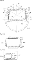
- Fig. 11 illustrates an example of a positional relationship among the image circle C1, a planar shape (a rectangular shape A1) corresponding to the effective region of the light valve 12, a planar shape (a rectangular shape A3) corresponding to the effective region of the image pickup device 13, and the channel regions (the channel regions CH1 to CH4). More specifically, these rectangular shapes A1 and A3 correspond to planar shapes at about a focal length of the projection lens.
- image circle represents a circular range where light having passed through a lens forms an image.
- the effective region of the light valve is designed to be secured at a position where the light valve is disposed.
- a region where a light beam emitted from the effective region of the light valve passes is designed to be secured in the projection lens.
- a region where a light beam entering the effective region of the image pickup device passes is designed to be secured in an image pickup lens.
- image projection and capturing of detected light are performed by one projection lens 16; therefore, the image circle (the image circle C1) may be desirably designed to secure a light beam passing through a portion with the highest image height.
- the ultra short throw projector is used; therefore, the image circle C1 is designed to secure a region where a light beam of which an image height is largely shifted (offset) along one direction (a Y direction in Fig. 11 in this case) passes.
- an image circle (an image circle C100) is designed to circumscribe some apexes of the rectangular shape A1 of the light valve 12. More specifically, the image circle C100 is designed to be in contact with a pair of apexes A11 and A12 sharing one long side in the rectangular shape A1.
- the image circle C100 is designed to circumscribe the rectangular shape A1, because since the diameter of the image circle is extremely large and the size of the projection lens is enormous, in terms of maintenance of characteristics and cost, it may be desirable that the diameter of the image circle be minimized.
- the projection lens 16 is shared between the projection optical system 10A and the detection optical system 10B, since there is a difference (an extension) between the reflection point and the virtual light emission point, it may be desirable to design the image circle C1 in consideration of this difference. More specifically, it may be desirable that the image circle C1 contain the rectangular shape A2 including a cover region A2a in consideration of the above-described difference, because object detection is possible even in a corner section (an apex portion) of the projection region S11.
- the rectangular shape A3 of the image pickup device 13 is designed to be larger in size than the rectangular shape A1 of the light valve 12.
- a diagonal size of the image pickup device 13 is configured to satisfy the following conditional expression (1), where “d1 is a diagonal size of the light valve 12, d2 is a diagonal size of the image pickup device 13, "beta” is an optical magnification of the detection optical system (where “beta” is larger than 1 in the zoom-out optical system, “beta” is smaller than 1 in an zoom-in optical system, and “beta” is equal to 1 in an equal magnification optical system).
- the detection optical system 10B includes the zoom-out optical system
- this "beta” is a zoom-out magnification of the zoom-out optical system 14, and "beta” is larger than 1.
- the diagonal size d1 is a diagonal size of the effective region of the light valve 12
- the diagonal size d2 is a diagonal size of the effective region of the image pickup device 13. Therefore, the channel regions CH1 to CH4 for out-of-region detection are allowed to be allocated to peripheral regions of the rectangular shape A1 of the light valve 12.
- the image circle C1 has free regions around the rectangular shapes A1 and A2, and the channel regions CH1 to CH4 are allowed to be allocated to the free regions.
- apexes A31 and A32 of the rectangular shape A3 of the image pickup device 13 may be configured to be in contact with the image circle C1, or apexes A31 and A32 of the rectangular shape A3 may be configured to be located outside of an outer circumference of the image circle C1.
- d1 is smaller than "beta" ⁇ d2 ;(1)
- the respective channel regions CH1 to CH4 may be provided to face, for example, respective sides of the rectangular shape A1, and each of the channel regions CH1 to CH4 may be a rectangular region having a longitudinal direction along an outer perimeter of the rectangular shape A1.
- this layout is merely an example. It may be only necessary that the channel regions CH1 to CH4 are allocated to regions located outside the outer perimeter of the rectangular shape A1 and inside the outer circumference of the image circle C1, and the number of the channel regions, the shapes, positions, and the like of the channel regions are not specifically limited.
- a plurality of channel regions may be allocated to one side of the rectangular shape A1 to increase functions that are to be executed. On the contrary, only one channel region may be provided around the rectangular shape A1. In this case, a description is given of a case where the respective channel regions CH1 to CH4 are allocated to face respective four sides of the rectangular shape A1 as an example.
- Fig. 12A illustrates an example of a layout on the projection surface 110, based on such channel setting.
- channel regions CH1a to CH4a are formed in peripheral regions of an image display region S11a corresponding to the above-described channel regions CH1 to CH4 in the projection surface 110.
- a width d may be desirably about 10 mm or more in a case where it is assumed that an operation is performed with use of a finger or a hand.
- the width d may be desirably about 30 mm or more, and more desirably about 50 mm or more. It is to be noted that a case where display (full-screen display, full-size display) in which the projection region S11 is equal in size to the image display region S11a is performed is illustrated.
- Input operations for execution of various functions are allowed to be set with use of these channel regions CH1 to CH4 (CH1a to CH4a).
- Functions that are to be executed are not specifically limited; however, the functions may be desirably functions unaccompanied by movement of an image. Examples of the functions may include turning on/off of the projection display unit 1, volume adjustment, screen size adjustment, page-turning, scrolling, open/close of a window screen, going back/forward, and the like. It is to be noted that a function of directly moving a displayed image (for example, flick, zooming in and out, rotation, and the like) may be desirably performed on the projected image as usual.
- the functions that are to be executed may include various functions in a case where it is desired to perform an operation without interfering with a displayed image, music, or any other screen information.
- various gestures with use of one or more of the channel regions CH1a to CH4a may be set.
- the input operations may include an operation of touching one of the channel regions CH1a to CH4a with a finger (the indicator 71) a plurality of times within a predetermined period (for example, tapping twice), an operation of continuously placing a finger or the like in one of the channel regions CH1a to CH4a within a predetermined period (for example, press-and-hold), an operation of touching one channel region of the channel regions CH1a to CH4a and then touching another channel region within a predetermined period, and an operation of concurrently touching two or more different channel regions of the channel regions CH1a to CH4a.
- in-region detection a combination of such out-of-region detection and normal detection in the projection region S11 (hereinafter referred to as "in-region detection") may be set.
- An example of the combination may be an operation of concurrently touching one channel region of the channel regions CH1a to CH4a and a selective region in the projection region S11.
- a plurality of times of the touch operation or a touch operation at a plurality of points may be desirably set as an input operation, because a wrong operation (an operation that is not intended by a user) is allowed to be prevented.
- a function In setting in which a function is executed by a touch operation only once or only at one point, the function may be executed even in a case where the user touches a channel region by mistake, thereby easily causing a malfunction.
- the examples may include a case where a function of turning on or off the projection display unit 1 is executed by allowing a detection signal to pass through the channel regions CH1a and CH2a within a predetermined period, a case where a function of turning down volume is executed by touching the channel region CH4 while touching the channel region CH3, and, conversely, a case where a function of turning up volume is executed by touching the channel region CH3 while touching the channel region CH4.
- a function of turning on or off the projection display unit 1 is executed by allowing a detection signal to pass through the channel regions CH1a and CH2a within a predetermined period
- a case where a function of turning down volume is executed by touching the channel region CH4 while touching the channel region CH3
- a function of turning up volume is executed by touching the channel region CH3 while touching the channel region CH4.
- a case where the entire projection region S11 serves as an image display region S11a is exemplified; however, a part of the projection region S11 may serve as the image display region S11a (an image is displayed or zoomed out in the part of the projection region S11).
- a case (in partial display) for example, as illustrated in Fig. 12B , channel regions CHlb to CH4b are formed in peripheral regions of the image display region S11a in the projection region S11 of the projection surface 110.
- a ratio of zooming in or out may be maintained by an operation of zooming in or out.
- the signal processing section 17 may be configured to detect, for example, a position of a characteristic point of the indicator (object) 71 such as a human finger or a pointer corresponding to coordinates in the projection region S11 on the projection surface 110, based on an image pickup signal by the image pickup device 13.
- a characteristic point a shape of a tip of the human finger, a barycenter of the finger, a barycenter of a hand, and the like may be used.
- a light reception amount in the image pickup device 13 differs by a difference in reflectivity between a finger and a stylus. Therefore, position detection may be performed only in a case where the indicator 71 is a specific one (for example, a finger) by setting of a threshold value.
- the signal processing section 17 determines, based on a thus-obtained object detection result, whether or not a specific input operation corresponding to the above-described function is performed. Moreover, as illustrated in Fig. 2 , a thus-obtained determination result D1 is outputted to the function control section 19.
- the function control section 19 is configured to perform control to execute a predetermined function, based on the determination result D1.
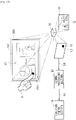
- image information V1 formed on the light valve12 is projected onto the projection surface 110 such as a top of a table by the projection lens 16 to be zoomed in as a projected image V2.
- the projection display unit 1 may detect a position of an object on the projection surface 110, for example, a position Pt1 of the characteristic point of the indicator (object) 71 such as a human finger or a pointer with use of an image pickup signal DO obtained from the image pickup device 13.
- the projection lens 16 is shared between the projection optical system 10A and the detection optical system 10B, and the image pickup device 13 is disposed in a position optically conjugating with the light valve 12. Therefore, object detection is possible in a region, serving as a detection region (a first detection region), that is substantially the same as the projection region S11a. Moreover, by such an optically conjugating positional relationship, the position Pt1 of the characteristic point of the indicator 71 on the projection surface 110 is allowed to be monitored through the projection lens 16 while being superimposed on the projected image V2.
- image processing may be performed on a shape of the indicator 71 to detect coordinates of the position Pt1 of the characteristic point of the indicator 71, thereby making a pointing operation on the projected image V2 possible.
- an arbitrary coordinate position in the projection region S11 corresponds to a coordinate position in the detection region on a one-to-one basis; therefore, coordinates of a detected position Pt2 on the image pickup device 13 correspond to coordinates of the position Pt1 of the characteristic point of the indicator 71.
- the object is allowed to be detected by associating a position in the projection region S11 and a position in the detection region with each other.
- the number of the indicators 71 may be two or more, and, for example, coordinates of tips of fingers of both hands may be detected.
- An intuitive operation as if a touch panel was built in the projected image V2 of the projector is possible with use of the detected position of the characteristic point of the indicator 71.
- the rectangular shape A3 of the image pickup device 13 is designed to allow the apexes A31 and A32 thereof to be in contact with the image circle C1 or partially protrude from the image circle C1. Therefore, an input operation (an input operation by a gesture) in a peripheral region of the image display region S11a (for example, the projection region S11) is allowed to be performed. Then, a function corresponding to this input operation is executed.
- FIG. 14A A flow of a function control operation, based on the above-described object detection and the above-described input operation is illustrated in Fig. 14A .
- the image display region S11a is equivalent to the projection region S11 (in a case of full-size display illustrated in Fig. 12A )
- an image is displayed in full size on the projection region S11 of the projection surface 110 (step S110).
- an object the indicator 71
- step S111 Whether or not a specific input operation is performed is determined, based on a thus-obtained object detection result (step S112).
- a function corresponding to the input operation is executed, based on a thus-obtained determination result (in a case where the specific input operation is detected) (step S113).
- a flow of a function control operation in a case where the image display region S11a is in a part of the projection region S11 (in the partial display illustrated in Fig. 12B ) is illustrated in Fig. 14B .
- a case of partial display first, an image is displayed on the part of the projection area S11 of the projection surface 110. After that, an object (the indicator 71) is detected in peripheral regions (the channel regions CHlb to CH4b) of the image display region S11a (step S115). Whether or not a specific input operation is performed is determined, based on a thus-obtained object detection result (step S116). Then, a function corresponding to the input operation is executed, based on a thus-obtained determination result (in a case where the specific input operation is detected) (step S117).
- FIG. 15 A schematic view of the function control example 1 is illustrated in Fig. 15 .
- a narrow operation part such as a button or a scroll
- the operation is more easily performed by touching a selective region (a region in proximity to any of the operation parts B11, B12, and B13) of the channel regions CH1a to CH4a, and a touch operation does not interfere with screen information.
- a function is executed only in a case where a predetermined region of the channel region CH1a and CH4a is also touched concurrently with the above-described input operation. For example, in a case where an operation of touching the channel region CH4a (or a part thereof) while touching the channel region CH3a (or a part thereof) is performed, a function such as a function of closing a window screen is executed. Therefore, a malfunction of the function is allowed to be prevented.
- An input operation in a case where it is not desired to interfere with an image, music, or any other screen information by a touch operation is performed out of the region to execute a function, for example, song forward, seek, and volume adjustment.
- a gesture of moving a position (a projection position) of the image display region is performed out of the region (in a peripheral region of the projection region S11 or the image display region S11a) to adjust the projection position.
- the projection surface 110 is not a flat surface, and has irregularities.
- a function of shifting the image display region S11a to a flat surface to avoid the irregularities is executed by an input operation out of the region.
- a function of zooming in or out the display screen size is executed by concurrently seeking a plurality of selective regions (for example, two sides or two corners) out of the region. Since detection of an image pointing operation is allocated to the projection region S11, a detection error or a malfunction is allowed to be prevented by an operation out of the region and a concurrent operation at a plurality of points.
- a function of detecting another electronic apparatus such as a smartphone or a tablet terminal placed in proximity to the projection region S11, developing, for example, a page icon on a standby screen on the projection region S11, and displaying an image of the electronic apparatus on a screen larger than the electronic apparatus is executed.
- a function of returning to a previous screen is executed by tapping a selective region out of the region twice. Tapping in the region twice is recognized as a normal double click operation, but tapping twice out of the region is allowed to be allocated to another operation.
- a function of displaying a keyboard is executed by long-pressing a selective region out of the region, for example, the channel region CH2a below the screen.
- a so-called multi-touch detection is allowed to be supported. More specifically, in a case where a plurality of users concurrently perform an input operation, or by an operation such as an operation of bringing a plurality of points closer to one another or separating a plurality of points from one another, zooming in or out of a displayed image is allowed to be performed.
- This multi-touch detection is advantageous, but may cause a detection error. For example, in a case where a user sits in front of the projection surface 110, and performs an operation, for example, writing or drawing, a position of a hand is fixed in general; therefore, such an operation is often performed in a state in which a palm of the user is in contact with the screen.
- a finger or the palm of the user may be concurrently detected, thereby causing a wrong operation.
- only a position of a finger tip is allowed to be selectively detected by signal processing with use of a difference in characteristic points between the finger tip and the palm; however, the following technique is allowed to be adopted.
- an operation of switching to a mode in which the position of one point (the finger tip) is allowed to be selectively detected is performed out of the region. More specifically, switching between a multipoint detection mode and a single point detection mode is performed by an input operation out of the region.
- multipoint detection and selective detection of only one point are allowed to be achieved by signal processing. For example, in a writing operation in the single-point detection mode, a relative positional relationship between the finger tip and the palm is almost unchanged; therefore, signal processing in which only a portion corresponding to the finger tip is considered as a detection target and a portion corresponding to the palm is not considered as a detection target, based on the positional relationship is performed. As a result, detection accuracy of the finger tip is improved to lead to an improvement in operability.
- the image pickup device 13 is disposed in a position optically conjugating with the light valve 12, and light, based on invisible light (a part of near-infrared light reflected by an object) enters the image pickup device 13 through the projection lens 16 and the polarization separation device 15. Therefore, the image pickup signal D0, based on the near-infrared light La1 is allowed to be obtained. An object around the image display region S11a is detected, based on the image pickup signal DO to determine whether or not a specific input operation is performed, and a specific function is executed, based on a thus-obtained determination result.
- an input operation for execution of a function is possible in not only the image display region S11a (for example, the projection region S11) but also a region where an image is not displayed, and an enhancement of flexibility of the input operation is possible. Therefore, an improvement in operability by the user is possible.
- the present disclosure is not limited to description of the above-described embodiment, and various modifications are possible.
- the light valve 12 and the image pickup device 13 a light valve and an image pickup device having substantially the same aspect ratio are exemplified; however, the light valve 12 and the image pickup device 13 may not necessarily have the same aspect ratio.
- the light valve of the present disclosure a reflective liquid crystal device is used; however, the light valve of the present disclosure is not limited thereto, and any other light valve may be used.
- a digital mirror device DMD
- the light valve is of a mirror type that does not use light polarization characteristics; therefore, a polarization optical system is not typically used; however, as with the above-described embodiment, an optical system in which a polarization separation device such as a polarizing beam splitter is provided in an optical path may be provided, and display image with use of the DMD is achievable.
- the projection display unit of the present disclosure a so-called ultra short throw projector is exemplified; however, the projection display unit of the present disclosure is not limited thereto, and the present disclosure is widely applicable to projectors of any other kinds. It is to be noted that the effects described in the above-described embodiment and the like are merely examples, and may be other effects, or may further include any other effects.
Landscapes
- Engineering & Computer Science (AREA)
- Theoretical Computer Science (AREA)
- General Engineering & Computer Science (AREA)
- Physics & Mathematics (AREA)
- General Physics & Mathematics (AREA)
- Human Computer Interaction (AREA)
- Multimedia (AREA)
- Computer Hardware Design (AREA)
- Signal Processing (AREA)
- Health & Medical Sciences (AREA)
- Computer Vision & Pattern Recognition (AREA)
- General Health & Medical Sciences (AREA)
- Psychiatry (AREA)
- Social Psychology (AREA)
- Projection Apparatus (AREA)
- Transforming Electric Information Into Light Information (AREA)
Description
- The present disclosure relates to a projection display unit having a detection function and a function control method using this projection display unit.
- In recent years, in smartphones, tablet terminals, and the like, use of a touch panel allows for page-turning and zooming in or out of an image displayed on a screen by an intuitive pointing operation. On the other hand, as a display unit configured to perform display by projecting an image on a screen, a projector (projection display unit) has been long known. There is proposed a technology to add a detection function such as a touch panel to the projector (for example, refer to PTLs 1 and 2).
-
- [PTL 1]
Japanese Unexamined Patent Application Publication No. 2007-52218 - [PTL 2]
Japanese Unexamined Patent Application Publication No. 2003-44839 - A projection display unit according to the preamble of claim 1 is known from
US 2012/0313910 A1 . This document discloses a protection display unit comprising an image pickup unit configured to receive invisible light emitted by an invisible light emitter to generate a pickup image. -
US 2004/0141162A1 discloses a projection display unit including a light engine configured to project an image onto a display surface, an image sensor configure to capture a presentation image larger than the projected image, and a processor coupled to the image sensor that is configured to modify the projected image based on the captured image. -
EP 3 550 359 A1 - Also,
US 2011/0241986 A1 relates to an interactive projection device including a projection optical system, a light source section configured to emit invisible light for detection of an input operation, a polarization separation device, and a detection optical system. - In a projector described in PTL 1, image projection by a projection optical system and capturing of detected light by a detection optical system are performed with use of one projection lens, and a light valve configured to produce an image and an image pickup device configured to receive detected light are disposed in positions optically conjugating with each other. Such a configuration allows for accurate object detection without performing a complicated process such as calibration. An interactive device is achievable with a simple configuration.
- In such a projector, it is desirable to achieve a technique of allowing for an improvement in operability by a user possible.
- It is desirable to provide a projection display unit and a function control method that allow for an improvement in operability by a user.
- According to the invention, a projection display unit and a function control method according to the independent claims are provided.
- In the projection display unit and the function control method according to the embodiments of the present disclosure, the image pickup device is disposed in the position optically conjugating with the light valve, and light, based on the invisible light (a part of invisible light reflected by the object) enters the image pickup device through the projection lens and the polarization separation device; therefore, an image pickup signal, based on the invisible light is allowed to be obtained. An object in a peripheral region of the projection region is allowed to be detected, based on the image pickup signal, and a function, based on a specific input operation is allowed to be executed accordingly. Therefore, an input operation is possible not only in the projection region but also the peripheral region of the projection region, and flexibility of the input operation is enhanced. Thus, an improvement in operability by a user is possible.
- It is to be noted that the above description is merely an example of the embodiments of the present disclosure. Effects of the embodiments of the present disclosure are not limited to effects described here, and may be different from the effects described here or may further include any other effect.
- It is to be understood that both the foregoing general description and the following detailed description are exemplary, and are intended to provide further explanation of the technology as claimed.
-
- [
fig.1] Fig. 1 is a schematic view illustrating an appearance and a usage state of a projection display unit according to an embodiment of the present disclosure. - [
fig.2]Fig. 2 is a block diagram illustrating a function configuration of the projection display unit illustrated inFig. 1 . - [
fig.3]Fig. 3 is a schematic side view of the state inFig. 1 . - [
fig.4]Fig. 4 is a diagram illustrating a configuration example of a near-infrared light source section illustrated inFig. 1 . - [
fig.5A]Fig. 5A is a perspective view of a first configuration example of a cylinder array lens. - [
fig.5B]Fig. 5B is a perspective view illustrating a second configuration example of the cylinder array lens. - [
fig.6]Fig. 6 is a diagram illustrating a configuration of a main part of the projection display unit illustrated inFig. 1 . - [
fig.7]Fig. 7 is a schematic view illustrating a configuration example of a polarization separation device with states of incident light and emitted light. - [
fig.8A]Fig. 8A is a schematic view illustrating capturing of detected light. - [
fig.8B]Fig. 8B is a schematic view for describing a difference in capturing angle between detected positions. - [
fig.9]Fig. 9 is a schematic view for describing a difference between a reflection point and a virtual light emission point of detected light. - [
fig. 10] Fig. 10 is a schematic view for describing a relationship between the difference between the reflection point and the virtual light emission point and the capturing angle. - [
fig.11] Fig. 11 is a schematic view illustrating an image circle of a projection lens with a light valve size and an image pickup device size. - [
fig.12A] Fig. 12A is a schematic view for describing a case where an out-of-region detection channel is used (in a case of full-size display). - [
fig.12B] Fig. 12B is a schematic view for describing a case where an in-region detection channel is used (in a case of partial display). - [
fig.13] Fig. 13 is a diagram schematically illustrating a concept of image display and object detection of the projection display unit illustrated inFig. 1 . - [
fig.14A] Fig. 14A is a flow chart illustrating a procedure of function control in the case where the out-of-region detection channel is used (in the case of full-size display). - [
fig.14B] Fig. 14B is a flow chart illustrating a procedure of function control in the case where the in-region detection channel is used (in the case of partial display). - [
fig.15] Fig. 15 is a schematic view for describing a function control example. - Some embodiments of the present disclosure will be described in detail below referring to the accompanying drawings. It is to be noted that description will be given in the following order.
× Embodiment (An example of a projection display unit in which channel regions for detection of a specific input operation are provided in and out of a projection region) - 1. Configuration
- 2. Action and Effects
-
Fig. 1 illustrates an appearance and a usage state of a projection display unit (a projection display unit 1) according to an embodiment of the present disclosure.Fig. 2 illustrates a function configuration of the projection display unit 1. The projection display unit 1 may be, for example, a projector (a so-called ultra short throw projector) configured to project an image in proximity thereto while being placed on a flat surface such as a top of a table (or while being mounted on a wall surface or the like). This projection display unit 1 also has a function of actively performing object detection in addition to image display. As will be described in detail later, as illustrated inFig. 1 , a user is allowed to perform a predetermined input operation by performing some operation such as touching a displayed image with his finger (an indicator 71) in a projection region S11 (a projectable region corresponding to a light valve size) where an image is projected. - As illustrated in
Fig. 2 , the projection display unit 1 includes anillumination section 11, a light valve 2, animage pickup device 13, a zoom-outoptical system 14, apolarization separation device 15, aprojection lens 16, asignal processing section 17, and afunction control section 19. Theillumination section 11, thelight valve 12, and theprojection lens 16 configure a projectionoptical system 10A, and theimage pickup device 13 and the zoom-outoptical system 14 configure a detectionoptical system 10B. It is to be noted that, for example, driving of theillumination section 11, thelight valve 12, theimage pickup device 13, thesignal processing section 17, and thefunction control section 19 may be controlled by a system control section (not illustrated) at a predetermined timing. - A near-infrared
light source section 40 is provided on a casing of the projection display unit 1. The near-infraredlight source section 40 is a light source section configured to emit near-infrared light (NIR) as invisible light for detection, and is configured to emit near-infrared light along a plane in proximity to aprojection surface 110. In other words, in the near-infraredlight source section 40, a near-infrared light barrier film (adetection light plane 110A) is formed in proximity to theprojection surface 110 to cover the projection region S11. Thedetection light plane 110A is formed in a plane at a predetermined height h, which is different from a height of an optical axis passing through theprojection lens 16, from the projection surface 1110 (refer toFig. 3 ). - As an example, the
detection light plane 110A may be formed, for example, with a thickness (a width in a height direction) of about 2 mm to about 3 mm in a position at the height h of about several mm to about several tens of mm to cover the projection region S11 in an in-plane direction. In general, theprojection surface 110 is flat; therefore, as long as a shielding object or theindicator 71 such as a finger and a pointer is not present, thedetection light plane 110A is not blocked. In other words, no image appears on theimage pickup device 13 that monitors theprojection surface 110. When an operation of moving a finger or the like close to theprojection surface 110 or touching theprojection surface 110 with the finger or the like is performed in this state, near-infrared light of thedetection light plane 110A is blocked by the finger or the like, and is diffused and reflected at a point where the near-infrared light of thedetection light plane 110 is blocked. Light reflected by the finger or the like radiates in all directions, and a part of the reflected light is captured in an aperture of theprojection lens 16. The part of the reflected light reaches theimage pickup device 13 through theprojection lens 16 and thepolarization separation device 15. At this time, thelight valve 12 configured to produce an image, and theimage pickup device 13 are disposed in positions optically conjugated with each other; therefore, a bright spot diffusion point generated in a dot shape on theprojection surface 110 forms an image on theimage pickup device 13, and forms an image in a corresponding position on the projected image. Therefore, position detection of an object is possible. In a case of the ultra short throw projector, projected light passes in proximity to theprojection surface 110, and a part of a body of a user who operates the projector is less likely to block the projected light; therefore, there is an advantage that a screen is easily seen when the user operates the projector. - It is to be noted that the near-infrared
light source section 40 may be provided, for example, on a bottom of the casing of the projection display unit 1, as illustrated; however, the near-infraredlight source section 40 may be or may not be disposed adjacent to the projection display unit 1. As long as thedetection light plane 110A is allowed to be formed to cover the projection region S11, thedetection light source 110 may be disposed in a position away from the projection display unit 1. Alternatively, the near-infraredlight source section 40 may be disposed inside the casing (an enclosure) of the projection display unit 1. In this embodiment, the near-infraredlight source section 40 is allowed to be disposed at a height relatively away from theprojection surface 110 by optical design that will be described later, and is easily bundled integrally with the projection display unit 1 accordingly. - When the object (the indicator 71) comes into contact with or comes close to the
projection surface 110, thedetection light plane 110A allows near-infrared light to be reflected (diffused and reflected) by theindicator 71, and then allows a part of the reflected light to be captured in the projection display unit 1 as detected light. - As illustrated in
Fig. 4 , the near-infraredlight source section 40 may include, for example, a near-infrared laser 42, acollimator lens 43, and acylinder array lens 44. Thedetection light plane 110A is formed of near-infrared light 41 emitted from thecylinder array lens 44. As illustrated inFig. 5A , thecylinder array lens 44 is configured of an array of a plurality of convex cylinder lenses. Thecylinder array lens 44 is disposed to allow ageneratrix 44A of each cylinder lens to face a plane perpendicular to theprojection surface 110. It is to be noted that, instead of the convexcylinder array lens 44, acylinder array lens 45 configured of an array of a plurality of concave cylinder lenses may be used. - The
illumination section 11 is configured to emit illumination light L1 toward thelight valve 12 through thepolarization separation device 15. As long as theillumination section 11 emits visible light as the illumination light L1, theillumination section 11 is not specifically limited. Theillumination section 11 may include, for example, a blue laser, a green laser, and a red laser (all of which are not illustrated). - Referring to
Fig. 2 andFigs. 6 to 12B , a configuration of a main part of the projection display unit 1 will be described below. - The
light valve 12 may be a reflective liquid crystal device such as LCOS (Liquid Crystal On Silicon). Thelight valve 12 may be configured to modulate a first polarized component (for example, an s-polarized component Ls1 that will be described later) included in the illumination light L1, based on image data. A polarization state of light modulated by thelight valve 12 is rotated, and thus the light is converted into a second polarized component (for example, a p-polarized component that will be described alter). This modulated light is emitted toward theprojection lens 16 through thepolarization separation device 15. It is to be noted that, in thelight valve 12, black display is allowed to be performed by returning incident light (the s-polarized component Ls1) to thepolarization separation device 15 without changing the polarization state thereof. A planar shape of an effective region (a rectangular shape A1 that will be described later) of thelight valve 12 is rectangular. - The
projection lens 16 is configured to project, onto theprojection surface 110, light (image light L2) having entered from thelight valve 12 through thepolarization separation device 15. Theprojection lens 16 may be, for example, an ultra short throw lens with a throw ratio of about 0.38 or less. Herein, the throw ratio is represented by L/H, where a distance from theprojection lens 16 to theprojection surface 110 is L and a width of the projection region S11 is H. As illustrated inFigs. 2 and6 , detected light (near-infrared light La1) enters thisprojection lens 16 from an opposite direction to a travel direction of modulated light. Thus, in this embodiment, the detected light is captured through theprojection lens 16 of the projectionoptical system 10A to be guided to the detectionoptical system 10B. Moreover, as will be described later, a diameter of an image circle by theprojection lens 16 is set within a predetermined range. - The
polarization separation device 15 is configured to separate incident light into the first polarized component (for example, an s-polarized component) and the second polarized component (for example, a p-polarized component) and emit the first and second polarized components in different directions from each other. Thispolarization separation device 15 may be configured of, for example, a polarizing beam splitter (PBS), and may be configured to selectively reflect the first polarized component (reflect the first polarized component on a polarization separation surface 150) and allow the second polarized component to selectively pass therethrough (pass through the polarization separation surface 150). In this embodiment, description is given of a case where the polarizing beam splitter is used as thepolarization separation device 15 as an example; however, thepolarization separation device 15 is not limited thereto, and may be configured of a wire grid. In this case, the wire grid has different characteristics from those of the polarizing beam splitter, and is allowed to selectively reflect the p-polarized component as the first polarized component of incident light and allow the s-polarized component of the incident light as the second polarized component to selectively pass therethrough. - As illustrated in
Fig. 6 , thispolarization separation device 15 may have four optical surfaces (afirst surface 15A, asecond surface 15B, a third surface 15C, and afourth surface 15D) and thepolarization separation surface 150. Thefirst surface 15A and the third surface 15C are disposed to face each other in one axis direction (a horizontal direction in the diagram), and thesecond surface 15B and thefourth surface 15D are disposed to face each other in one axis direction (a vertical direction in the diagram). In such a configuration, the illumination light L1 enters thefirst surface 15A, and thelight valve 12 is disposed to face thesecond surface 15B. The detectionoptical system 10B is disposed to face the third surface 15C, and theprojection lens 15 is disposed to face thefourth surface 15D. -
FIG. 7 illustrates a configuration example of thepolarization separation device 15. Thepolarization separation device 15 reflects the first polarization component (the s-polarized component Ls1) of the illumination light L1 having entered from thefirst surface 15A and emits the first polarization component from thesecond surface 15B. On the other hand, thepolarization separation device 15 emits, from the third surface 15C, the second polarized component (a p-polarized component Lp1) of the illumination light L1. Moreover, thepolarization separation device 15 emits, from thefourth surface 15D, the second polarized component (a p-polarized component Lp2) of light having entered from thesecond surface 15B (modulated light from the light valve 12). Therefore, an image is projected by the projectionoptical system 10A. On the other hand, thepolarization separation device 15 reflects the first polarized component (an s-polarized component Ls3) of light (the near-infrared light La1) having entered from thefourth surface 15D, and emits the first polarized component from the third surface 15C. Light, based on this s-polarized component Ls3 is received by theimage pickup device 13. Thus, an image pickup signal DO is obtained by theimage pickup device 13. - The
image pickup device 13 is disposed in a position optically conjugating with thelight valve 12. More specifically, in a case where thelight valve 12 is a reflective liquid crystal device, a display surface (a liquid crystal surface) where an image is produced of thelight valve 12 and an image pickup surface of theimage pickup device 13 are disposed to have an optically conjugating relationship therebetween. Theimage pickup device 13 may be configured of a solid-state image pickup device such as a CMOS (Complementary Metal-Oxide Semiconductor) or a CCD (Charge Coupled Device), and the planar shape of the effective region (a rectangular shape A3 that will be described later) is rectangular. In this embodiment, as will be described in detail later, the size of theimage pickup device 13 is designed to allow a peripheral region of the projection region S11 to also serve as a light reception target. - As illustrated in
Fig. 6 , an example of the detectionoptical system 10B including thisimage pickup device 13 may be a detection optical system in which a visible light cutfilter 17A, abandpass filter 17B, a zoom-out optical system 14 (relay lens groups polarizer 18, and theimage pickup device 13 are arranged in order from aconjugate plane 50. - The visible light cut
filter 17A is configured to reduce a visible light component of incident light. When this visible light cutfilter 17A is provided, even if the polarizing beam splitter is used as thepolarization separation device 15, a large amount of the illumination light L1 having entered theimage pickup device 13 is allowed to be cut without turning off a light source of theillumination section 11. Therefore, nearly only detected light is allowed to enter theimage pickup device 13, and an S/N ratio is allowed to be increased, thereby enhancing detection accuracy. It is to be noted that, although one visible light cutfilter 17A is provided in this case, the number of visible light cut filters is not limited to one, and may be two or more. Moreover, although the visible light cutfilter 17A is disposed in a position between theconjugate plane 50 and the zoom-outoptical system 14 in this case, the visible light cutfilter 17A may be disposed in another position, for example, between the zoom-outoptical system 14 and theimage pickup device 13. - The
bandpass filter 17B is configured to allow a specific wavelength (near-infrared light) to selectively pass therethrough and to reduce other wavelengths. - The
polarizer 18 is an optical member configured to reduce the second polarized component included in the illumination light L1. In this case, thepolarization separation device 15 as described above allows the second polarized component (for example, the p-polarized component) of the illumination light L1 to pass therethrough; therefore, this p-polarized component may enter the detectionoptical system 10B, thereby influencing an S/N ratio of an image pickup signal obtained in theimage pickup device 13. As with this embodiment, when thepolarizer 18 is provided, the second polarized component (for example, the p-polarized component) included in the illumination light L1 is allowed to be cut, thereby enhancing the S/N ratio. It is to be noted that the position of thepolarizer 18 is not limited to the illustrated position between the zoom-outoptical system 14 and theimage pickup device 13, and thepolarizer 18 may be disposed in another position, for example, between theconjugate plane 50 and the zoom-outoptical system 14. - The zoom-out
optical system 14 may be configured of one or a plurality of relay lens groups (tworelay lens groups relay lens groups relay lens group 14B is set to be smaller than a focal length fb of therelay lens group 14A. For example, on condition that 2fi is equal to fb, therelay lens group 14A may be disposed in a position at a distance equal to the focal length fb from theconjugate plane 50 of thelight valve 12, therelay lens group 14B may be disposed in a position at a distance of (fb+fi) from the position of therelay lens group 14A, and theimage pickup device 13 may be disposed in a position at a distance equal to the focal length fi from therelay lens 14B. Such arrangement of therelay lens groups image pickup device 13 is disposed on theconjugate plane 50 while achieving the zoom-out optical system. In other words, while a position relationship conjugating with thelight valve 12 is maintained, a further reduction in the size of theimage pickup device 13 is possible. - Object detection with use of such a zoom-out
optical system 14 is advantageous for cost reduction. The cost of theimage pickup device 13 is greatly influenced by the size of theimage pickup device 13. Cost of configuring the projector is weighted heavily toward thelight valve 12 and theimage pickup device 13 as semiconductor components; therefore, a cost advantage by a size reduction in such components is large. Moreover, there is an advantage that flexibility of arrangement is enhanced by extending a conjugate point by a relay optical system. For example, when a distance between components is produced, a bending optical system configured of a reflective mirror may be achieved between the components. - In this embodiment, a region (a second detection region) where object detection is possible is formed in a peripheral region of the projection region S11 on the projection surface. A channel region (channel regions CH1a to Ch4a that will be described later and the like) corresponding to a specific input operation is allocated to this second detection region. In other words, object detection is possible in the peripheral region of the projection region S11 (hereinafter referred to as "out of the region"), and when the specific input operation is performed out of the region, a function corresponding to the input operation is executed. It is to be noted that the specific input operation may be allocated to not the channel region but position coordinates. A specific configuration configured to achieve the input operation by such out-of-region detection will be described below.
- First, a summary of capturing of detected light will be described. As schematically illustrated in
Fig. 8A , when anindicator 71 such as a finger comes in contact with or comes close to theprojection surface 110, near-infrared light La in thedetection light plane 110A formed in proximity to theprojection surface 110 strikes theindicator 71 to be diffused and reflected in all directions. After a part (near-infrared light La1) of the diffused and reflected light (scattering light) is condensed by theprojection lens 16, the part of the diffused and reflected light is taken by the exit pupil E1 in the detectionoptical system 10B. - Now, the near-infrared light La1 captured by the detection
optical system 10B through theprojection lens 16 in the above-described manner will be described in detail below. As illustrated inFig. 8B , in a case where a position of an object on theprojection surface 110 is detected, a capturing angle of the near-infrared light La1 (an angle "theta" between the near-infrared light la1 entering the exit pupil E1 of the detectionoptical system 10B and the projection surface 110) differs depending on the detected position. More specifically, when viewed from a position P1 closest to the exit pupil E1, the exit pupil E1 is located above the position PI; therefore, the capturing angle "theta" is at the maximum. Next, as a distance from the exit pupil E1 is gradually increased in order of positions P2 and P3, the capturing angle "theta" is gradually reduced. A position P4 is farthest from the exit pupil E1, and at the position P4, the capturing angle "theta" is at the minimum. - As described above, it is found that the distance to the exit pupil E1 or the capturing angle "theta" is changed by a difference in the detected position. Values of these parameters differ depending on a size of the projection region S11, ultra short throw lens design, or the like; however, a relative magnitude relationship of the capturing angle "theta" by the above-described difference in the detected position is not changed; therefore, the position of the
indicator 71 is allowed to be determined with use of this relationship. - Next, the near-infrared light La1 entering the exit pupil E1 will be studied in more detail.
Fig. 9 schematically illustrates a state of reflection around theindicator 71. It is to be noted that an upper diagram inFig. 9 illustrates reflection at the position P1 and a lower diagram inFig. 9 illustrates reflection at the position P4. As illustrated inFig. 9 , the near-infrared light La in the detectionlight surface 110 strikes theindicator 71 and is reflected by theindicator 71, and at this time, the following phenomenon occurs. In this embodiment, the near-infrared light La1 when viewed from the exit pupil E1 (the projection lens 16) seems to be emitted from not reflection points (actual irradiation points) Pa1 and Pa2 where the near-infrared light La1 actually strikes theindicator 71 but points (virtual light emission points Pb1 and Pb2) on theprojection surface 110 located at a distance corresponding to an oblique component by a height h. In other words, a difference t1 is made between the reflection point Pa1 corresponding to the actual position of theindicator 71 and the virtual light emission point Pb1. Likewise, a difference is made between the reflection point Pa2 and the virtual light emission point Pb2. Moreover, this difference (an extension in the detected position) is influenced by the detected position, i.e., the capturing angle "theta", and the smaller the capturing angle "theta" is, the more the difference is influenced. In this case, since the capturing angle "theta" at the position P4 is at the minimum, the difference t2 at the position P2 has a maximum value. It is to be noted that, since the capturing angle "theta" at the position P1 is at the maximum, the difference t1 at the position P1 has a minimum value. - Therefore, to make object detection in the entire projection region S11 possible, as illustrated in
Fig. 10 , the size of theimage pickup device 13, the diameter of an image circle (an image circle C1 that will be described later), and the like are so designed as to allow an region (an region S12) in consideration of a width t corresponding to the above-described difference from an end of the projection region S11 to serve as a light reception target. It is to be noted that the width t is allowed to be represented with use of the height h of thedetection light plane 110A and the capturing angle "theta"
-
Fig. 11 illustrates an example of a positional relationship among the image circle C1, a planar shape (a rectangular shape A1) corresponding to the effective region of thelight valve 12, a planar shape (a rectangular shape A3) corresponding to the effective region of theimage pickup device 13, and the channel regions (the channel regions CH1 to CH4). More specifically, these rectangular shapes A1 and A3 correspond to planar shapes at about a focal length of the projection lens. In general, "image circle" represents a circular range where light having passed through a lens forms an image. In a projection system such as a projector, the effective region of the light valve is designed to be secured at a position where the light valve is disposed. In other words, a region where a light beam emitted from the effective region of the light valve passes is designed to be secured in the projection lens. On the other hand, in a case of an image pickup system such as a camera, a region where a light beam entering the effective region of the image pickup device passes is designed to be secured in an image pickup lens. In this embodiment, image projection and capturing of detected light (near-infrared light) are performed by oneprojection lens 16; therefore, the image circle (the image circle C1) may be desirably designed to secure a light beam passing through a portion with the highest image height. - Moreover, in this case, the ultra short throw projector is used; therefore, the image circle C1 is designed to secure a region where a light beam of which an image height is largely shifted (offset) along one direction (a Y direction in
Fig. 11 in this case) passes. In this case, in a case of a projector configured to only project an image, an image circle (an image circle C100) is designed to circumscribe some apexes of the rectangular shape A1 of thelight valve 12. More specifically, the image circle C100 is designed to be in contact with a pair of apexes A11 and A12 sharing one long side in the rectangular shape A1. The image circle C100 is designed to circumscribe the rectangular shape A1, because since the diameter of the image circle is extremely large and the size of the projection lens is enormous, in terms of maintenance of characteristics and cost, it may be desirable that the diameter of the image circle be minimized. - However, in a case where, as with this embodiment, the
projection lens 16 is shared between the projectionoptical system 10A and the detectionoptical system 10B, since there is a difference (an extension) between the reflection point and the virtual light emission point, it may be desirable to design the image circle C1 in consideration of this difference. More specifically, it may be desirable that the image circle C1 contain the rectangular shape A2 including a cover region A2a in consideration of the above-described difference, because object detection is possible even in a corner section (an apex portion) of the projection region S11. - To secure a detection region in a peripheral portion of the projection region S11, the rectangular shape A3 of the
image pickup device 13 is designed to be larger in size than the rectangular shape A1 of thelight valve 12. In other words, a diagonal size of theimage pickup device 13 is configured to satisfy the following conditional expression (1), where d1 is a diagonal size of thelight valve 12, d2 is a diagonal size of theimage pickup device 13, "beta" is an optical magnification of the detection optical system (where "beta" is larger than 1 in the zoom-out optical system, "beta" is smaller than 1 in an zoom-in optical system, and "beta" is equal to 1 in an equal magnification optical system). However, since the detectionoptical system 10B includes the zoom-out optical system, this "beta" is a zoom-out magnification of the zoom-outoptical system 14, and "beta" is larger than 1. It is to be noted that the diagonal size d1 is a diagonal size of the effective region of thelight valve 12, and the diagonal size d2 is a diagonal size of the effective region of theimage pickup device 13. Therefore, the channel regions CH1 to CH4 for out-of-region detection are allowed to be allocated to peripheral regions of the rectangular shape A1 of thelight valve 12. In other words, the image circle C1 has free regions around the rectangular shapes A1 and A2, and the channel regions CH1 to CH4 are allowed to be allocated to the free regions. Moreover, apexes A31 and A32 of the rectangular shape A3 of theimage pickup device 13 may be configured to be in contact with the image circle C1, or apexes A31 and A32 of the rectangular shape A3 may be configured to be located outside of an outer circumference of the image circle C1. d1 is smaller than "beta"∗d2 ......(1) - The respective channel regions CH1 to CH4 may be provided to face, for example, respective sides of the rectangular shape A1, and each of the channel regions CH1 to CH4 may be a rectangular region having a longitudinal direction along an outer perimeter of the rectangular shape A1. However, this layout is merely an example. It may be only necessary that the channel regions CH1 to CH4 are allocated to regions located outside the outer perimeter of the rectangular shape A1 and inside the outer circumference of the image circle C1, and the number of the channel regions, the shapes, positions, and the like of the channel regions are not specifically limited. Moreover, a plurality of channel regions may be allocated to one side of the rectangular shape A1 to increase functions that are to be executed. On the contrary, only one channel region may be provided around the rectangular shape A1. In this case, a description is given of a case where the respective channel regions CH1 to CH4 are allocated to face respective four sides of the rectangular shape A1 as an example.
-
Fig. 12A illustrates an example of a layout on theprojection surface 110, based on such channel setting. Thus, channel regions CH1a to CH4a are formed in peripheral regions of an image display region S11a corresponding to the above-described channel regions CH1 to CH4 in theprojection surface 110. In these channel regions CH1a to CH4a, a width d may be desirably about 10 mm or more in a case where it is assumed that an operation is performed with use of a finger or a hand. Moreover, the width d may be desirably about 30 mm or more, and more desirably about 50 mm or more. It is to be noted that a case where display (full-screen display, full-size display) in which the projection region S11 is equal in size to the image display region S11a is performed is illustrated. - Input operations for execution of various functions are allowed to be set with use of these channel regions CH1 to CH4 (CH1a to CH4a). Functions that are to be executed are not specifically limited; however, the functions may be desirably functions unaccompanied by movement of an image. Examples of the functions may include turning on/off of the projection display unit 1, volume adjustment, screen size adjustment, page-turning, scrolling, open/close of a window screen, going back/forward, and the like. It is to be noted that a function of directly moving a displayed image (for example, flick, zooming in and out, rotation, and the like) may be desirably performed on the projected image as usual.
- The functions that are to be executed may include various functions in a case where it is desired to perform an operation without interfering with a displayed image, music, or any other screen information.
- As input operations for execution of the above-described functions, for example, various gestures with use of one or more of the channel regions CH1a to CH4a may be set. Examples of the input operations may include an operation of touching one of the channel regions CH1a to CH4a with a finger (the indicator 71) a plurality of times within a predetermined period (for example, tapping twice), an operation of continuously placing a finger or the like in one of the channel regions CH1a to CH4a within a predetermined period (for example, press-and-hold), an operation of touching one channel region of the channel regions CH1a to CH4a and then touching another channel region within a predetermined period, and an operation of concurrently touching two or more different channel regions of the channel regions CH1a to CH4a. Alternatively, a combination of such out-of-region detection and normal detection in the projection region S11 (hereinafter referred to as "in-region detection") may be set. An example of the combination may be an operation of concurrently touching one channel region of the channel regions CH1a to CH4a and a selective region in the projection region S11.
- Thus, while the plurality of channel regions CH1a to CH4a are provided, a plurality of times of the touch operation or a touch operation at a plurality of points may be desirably set as an input operation, because a wrong operation (an operation that is not intended by a user) is allowed to be prevented. In setting in which a function is executed by a touch operation only once or only at one point, the function may be executed even in a case where the user touches a channel region by mistake, thereby easily causing a malfunction.
- Specific examples of the above-described input operations and functions may be described below. The examples may include a case where a function of turning on or off the projection display unit 1 is executed by allowing a detection signal to pass through the channel regions CH1a and CH2a within a predetermined period, a case where a function of turning down volume is executed by touching the channel region CH4 while touching the channel region CH3, and, conversely, a case where a function of turning up volume is executed by touching the channel region CH3 while touching the channel region CH4. Other examples of the input operations and the functions will be described later.
- Moreover, a case where the entire projection region S11 serves as an image display region S11a is exemplified; however, a part of the projection region S11 may serve as the image display region S11a (an image is displayed or zoomed out in the part of the projection region S11). In such a case (in partial display), for example, as illustrated in
Fig. 12B , channel regions CHlb to CH4b are formed in peripheral regions of the image display region S11a in the projection region S11 of theprojection surface 110. Moreover, a ratio of zooming in or out may be maintained by an operation of zooming in or out. - The
signal processing section 17 may be configured to detect, for example, a position of a characteristic point of the indicator (object) 71 such as a human finger or a pointer corresponding to coordinates in the projection region S11 on theprojection surface 110, based on an image pickup signal by theimage pickup device 13. As an example of the characteristic point, a shape of a tip of the human finger, a barycenter of the finger, a barycenter of a hand, and the like may be used. Moreover, a light reception amount in theimage pickup device 13 differs by a difference in reflectivity between a finger and a stylus. Therefore, position detection may be performed only in a case where theindicator 71 is a specific one (for example, a finger) by setting of a threshold value. Thesignal processing section 17 determines, based on a thus-obtained object detection result, whether or not a specific input operation corresponding to the above-described function is performed. Moreover, as illustrated inFig. 2 , a thus-obtained determination result D1 is outputted to thefunction control section 19. - The
function control section 19 is configured to perform control to execute a predetermined function, based on the determination result D1. - In the projection display unit 1, as illustrated in
Fig. 13 , image information V1 formed on the light valve12 is projected onto theprojection surface 110 such as a top of a table by theprojection lens 16 to be zoomed in as a projected image V2. On the other hand, the projection display unit 1 may detect a position of an object on theprojection surface 110, for example, a position Pt1 of the characteristic point of the indicator (object) 71 such as a human finger or a pointer with use of an image pickup signal DO obtained from theimage pickup device 13. - In this case, in this embodiment, the
projection lens 16 is shared between the projectionoptical system 10A and the detectionoptical system 10B, and theimage pickup device 13 is disposed in a position optically conjugating with thelight valve 12. Therefore, object detection is possible in a region, serving as a detection region (a first detection region), that is substantially the same as the projection region S11a. Moreover, by such an optically conjugating positional relationship, the position Pt1 of the characteristic point of theindicator 71 on theprojection surface 110 is allowed to be monitored through theprojection lens 16 while being superimposed on the projected image V2. Moreover, for example, in thesignal processing section 17, image processing may be performed on a shape of theindicator 71 to detect coordinates of the position Pt1 of the characteristic point of theindicator 71, thereby making a pointing operation on the projected image V2 possible. At this time, an arbitrary coordinate position in the projection region S11 corresponds to a coordinate position in the detection region on a one-to-one basis; therefore, coordinates of a detected position Pt2 on theimage pickup device 13 correspond to coordinates of the position Pt1 of the characteristic point of theindicator 71. In other words, without performing complicated signal processing such as calibration, the object is allowed to be detected by associating a position in the projection region S11 and a position in the detection region with each other. It is to be noted that the number of theindicators 71 may be two or more, and, for example, coordinates of tips of fingers of both hands may be detected. An intuitive operation as if a touch panel was built in the projected image V2 of the projector is possible with use of the detected position of the characteristic point of theindicator 71. - Moreover, as illustrated in
Fig. 11 , when the rectangular shape A3 of theimage pickup device 13 is larger than the rectangular shape A1 of thelight valve 12, and the diameter of the image circle C1 is optimized, the object is easily detected even in a local region such as a corner section of the projection region S11, and object detection is possible in almost the entire projection region S11. Moreover, the rectangular shape A3 of theimage pickup device 13 is designed to allow the apexes A31 and A32 thereof to be in contact with the image circle C1 or partially protrude from the image circle C1. Therefore, an input operation (an input operation by a gesture) in a peripheral region of the image display region S11a (for example, the projection region S11) is allowed to be performed. Then, a function corresponding to this input operation is executed. - A flow of a function control operation, based on the above-described object detection and the above-described input operation is illustrated in
Fig. 14A . For example, in a case where the image display region S11a is equivalent to the projection region S11 (in a case of full-size display illustrated inFig. 12A ), first, an image is displayed in full size on the projection region S11 of the projection surface 110 (step S110). After that, in the peripheral regions (the channel regions CH1a to CH4a) of the image display region S11a (the projection region S11), an object (the indicator 71) is detected (step S111). Whether or not a specific input operation is performed is determined, based on a thus-obtained object detection result (step S112). Then, a function corresponding to the input operation is executed, based on a thus-obtained determination result (in a case where the specific input operation is detected) (step S113). - Moreover, a flow of a function control operation in a case where the image display region S11a is in a part of the projection region S11 (in the partial display illustrated in
Fig. 12B ) is illustrated inFig. 14B . In a case of partial display, first, an image is displayed on the part of the projection area S11 of theprojection surface 110. After that, an object (the indicator 71) is detected in peripheral regions (the channel regions CHlb to CH4b) of the image display region S11a (step S115). Whether or not a specific input operation is performed is determined, based on a thus-obtained object detection result (step S116). Then, a function corresponding to the input operation is executed, based on a thus-obtained determination result (in a case where the specific input operation is detected) (step S117). - Examples of the input operation using the channel regions CH1a to CH4a (and also the channel regions CHlb to CH4b) and a function executed by the input operation will be described below.
- An operation in relatively fine narrow parts provided in peripheral regions and corner sections such as a start button, a close button, and a vertical scroll bar of a screen is performed with use of the channel regions CH1a to CH4a allocated to regions around the parts. A schematic view of the function control example 1 is illustrated in
Fig. 15 . Compared to a case where an operation is performed by directly touching a narrow operation part (such as a button or a scroll) B11, B12, B13, or the like in the screen, the operation is more easily performed by touching a selective region (a region in proximity to any of the operation parts B11, B12, and B13) of the channel regions CH1a to CH4a, and a touch operation does not interfere with screen information. - A function is executed only in a case where a predetermined region of the channel region CH1a and CH4a is also touched concurrently with the above-described input operation. For example, in a case where an operation of touching the channel region CH4a (or a part thereof) while touching the channel region CH3a (or a part thereof) is performed, a function such as a function of closing a window screen is executed. Therefore, a malfunction of the function is allowed to be prevented.
- An input operation in a case where it is not desired to interfere with an image, music, or any other screen information by a touch operation is performed out of the region to execute a function, for example, song forward, seek, and volume adjustment.
- A gesture of moving a position (a projection position) of the image display region is performed out of the region (in a peripheral region of the projection region S11 or the image display region S11a) to adjust the projection position. For example, in a case where a book, a cup, or the like is placed on a desk, the
projection surface 110 is not a flat surface, and has irregularities. In a case where an object causing such irregularities is placed, or the like, a function of shifting the image display region S11a to a flat surface to avoid the irregularities is executed by an input operation out of the region. - A function of zooming in or out the display screen size is executed by concurrently seeking a plurality of selective regions (for example, two sides or two corners) out of the region. Since detection of an image pointing operation is allocated to the projection region S11, a detection error or a malfunction is allowed to be prevented by an operation out of the region and a concurrent operation at a plurality of points.
- A function of detecting another electronic apparatus such as a smartphone or a tablet terminal placed in proximity to the projection region S11, developing, for example, a page icon on a standby screen on the projection region S11, and displaying an image of the electronic apparatus on a screen larger than the electronic apparatus is executed.
- A function of returning to a previous screen is executed by tapping a selective region out of the region twice. Tapping in the region twice is recognized as a normal double click operation, but tapping twice out of the region is allowed to be allocated to another operation.
- A function of displaying a keyboard is executed by long-pressing a selective region out of the region, for example, the channel region CH2a below the screen.
- A so-called multi-touch detection (multipoint detection) is allowed to be supported. More specifically, in a case where a plurality of users concurrently perform an input operation, or by an operation such as an operation of bringing a plurality of points closer to one another or separating a plurality of points from one another, zooming in or out of a displayed image is allowed to be performed. Application to this multi-touch detection is advantageous, but may cause a detection error. For example, in a case where a user sits in front of the
projection surface 110, and performs an operation, for example, writing or drawing, a position of a hand is fixed in general; therefore, such an operation is often performed in a state in which a palm of the user is in contact with the screen. In such a case, a finger or the palm of the user may be concurrently detected, thereby causing a wrong operation. In such a case, only a position of a finger tip is allowed to be selectively detected by signal processing with use of a difference in characteristic points between the finger tip and the palm; however, the following technique is allowed to be adopted. - Even in a state in which the palm is in contact with the screen, an operation of switching to a mode in which the position of one point (the finger tip) is allowed to be selectively detected is performed out of the region. More specifically, switching between a multipoint detection mode and a single point detection mode is performed by an input operation out of the region. By such mode switching, multipoint detection and selective detection of only one point are allowed to be achieved by signal processing. For example, in a writing operation in the single-point detection mode, a relative positional relationship between the finger tip and the palm is almost unchanged; therefore, signal processing in which only a portion corresponding to the finger tip is considered as a detection target and a portion corresponding to the palm is not considered as a detection target, based on the positional relationship is performed. As a result, detection accuracy of the finger tip is improved to lead to an improvement in operability.
- As described above, in this embodiment, the
image pickup device 13 is disposed in a position optically conjugating with thelight valve 12, and light, based on invisible light (a part of near-infrared light reflected by an object) enters theimage pickup device 13 through theprojection lens 16 and thepolarization separation device 15. Therefore, the image pickup signal D0, based on the near-infrared light La1 is allowed to be obtained. An object around the image display region S11a is detected, based on the image pickup signal DO to determine whether or not a specific input operation is performed, and a specific function is executed, based on a thus-obtained determination result. Accordingly, an input operation for execution of a function is possible in not only the image display region S11a (for example, the projection region S11) but also a region where an image is not displayed, and an enhancement of flexibility of the input operation is possible. Therefore, an improvement in operability by the user is possible. - It is to be noted that the present disclosure is not limited to description of the above-described embodiment, and various modifications are possible. For example, in the above-described embodiment, as the
light valve 12 and theimage pickup device 13, a light valve and an image pickup device having substantially the same aspect ratio are exemplified; however, thelight valve 12 and theimage pickup device 13 may not necessarily have the same aspect ratio. - Moreover, in the above-described embodiment, as the light valve of the present disclosure, a reflective liquid crystal device is used; however, the light valve of the present disclosure is not limited thereto, and any other light valve may be used. For example, as the light valve, a digital mirror device (DMD) may be used. In this case, the light valve is of a mirror type that does not use light polarization characteristics; therefore, a polarization optical system is not typically used; however, as with the above-described embodiment, an optical system in which a polarization separation device such as a polarizing beam splitter is provided in an optical path may be provided, and display image with use of the DMD is achievable.
- Further, in the above-described embodiment, as an example of the projection display unit of the present disclosure, a so-called ultra short throw projector is exemplified; however, the projection display unit of the present disclosure is not limited thereto, and the present disclosure is widely applicable to projectors of any other kinds. It is to be noted that the effects described in the above-described embodiment and the like are merely examples, and may be other effects, or may further include any other effects.
-
- 1 projection display unit
- 12 light valve
- 13 image pickup device
- 14 zoom-out optical system
- 15 polarization separation device
- 16 projection lens
- 17 signal processing section
- 17A visible light cut filter
-
17B bandpass filter 18 polarizer - 19 function control section
- 110 projection plane
- 110A detection light plane
- 40 near-infrared light source section
- A1, A3 effective region
- C1, C100 image circle
- CH1 to CH4, CH1a to CH4a, CH1b to CH4b channel region
- E1 exit pupil
- S11 projection region
- S12 region
- L1 illumination light
- La, La1 near-infrared light
- Lp1, Lp2, Lp3 P-polarized component
- Ls1, Ls2, Ls3 S-polarized component
- V1 projected image
- V2 image information
Claims (12)
- A projection display unit (1) comprising:a projection optical system (10A) configured to project to a projection region (S11) on a projection surface (110), including:an illumination section (11),a projection lens (16), anda light valve (12);a light source section (40) configured to emit invisible light for detection of an input operation along a detection light plane (110A) in proximity to the projection surface (110);a polarization separation device (15); anda detection optical system (10B) including a a zoom-out optical system (14) and an image pickup device (13),wherein:the detection optical system (10B) is configured to detect whether the input operation is performed in a peripheral region outside the projection region (S11) on the projection surface (110), andin response to detection by the detection optical system (10B) in the peripheral region, a specific function is caused to be executed, wherein the detection optical system is further configured to capture a part of reflected light of the invisible light for detection of the input operation by the image pickup device (13) through the projection lens (16) and the polarization separation device (15), wherein the image pickup device (13) is disposed in a position optically conjugating with the light valve (12), and whereinthe light valve (12) has a first rectangular shape andthe image pickup device (13) has a second rectangular shape, the second rectangular shape has a diagonal size d2 and the first rectangular shape has a diagonal size d1, wherein the following is met: d1 < β · d2, wherein β is the zoom-out magnification of the zoom-out optical system (14) of the detection optical system (10B).
- The projection display unit according to claim 1, wherein the projection display unit is configured to cause a first detection region corresponding to the projection region (S11) and a second detection region corresponding to the peripheral region of the projection region to be formable on the projection surface (110).
- The projection display unit according to claim 2, wherein the second detection region has one or more channel regions (CH1, CH2, CH3, CH4) or position coordinates, the respective one or more channel regions (CH1, CH2, CH3, CH4) or position coordinates corresponding to respective input operations.
- The projection display unit according to claim 3, wherein at least one of the one or more channel regions (CH1, CH2, CH3, CH4) are provided to face each side of four sides of a rectangular shape of the projection region.
- The projection display unit according to claim 3, wherein in response to detection of an object (71) by the detection optical system (10B) a plurality of times within a predetermined period in one channel region of the plurality of channel regions (CH1, CH2, CH3, CH4), the specific function is caused to be executed.
- The projection display unit according to claim 3, wherein in response to continuous detection of an object (71) by the detection optical system (10B) within a predetermined period in one channel region of the plurality of channel regions (CH1, CH2, CH3, CH4), the specific function is caused to be executed.
- The projection display unit according to claim 3, wherein in response to detection of an object in one channel region of the plurality of channel regions (CH1, CH2, CH3, CH4) and of an object in another channel region of the plurality of channel regions within a predetermined period by the detection optical system (10B), the specific function is caused to be executed.
- The projection display unit according to claim 3, wherein in response to concurrent detection of objects in two or more different channel regions of the plurality of channel regions (CH1, CH2, CH3, CH4) by the detection optical system (10B), the specific function is caused to be executed.
- The projection display unit according to claim 3, wherein in response to concurrent detection of objects in one channel region of the plurality of channel regions (CH1, CH2, CH3, CH4) and a selective region in the first detection region, the specific function is caused to be executed.
- The projection display unit according to claim 2, wherein the first detection region includes one or more channel regions (CH1a, CH2a, CH3a, CH4a) around a selective image display region in the projection area, the respective one or more channel regions corresponding to respective input operations.
- The projection display unit according to claim 1, wherein the light valve (12) is configured to:modulate illumination light fed from the illumination section based on an image signal andemit the modulated illumination light to the projection lens.
- A function control method comprising:projecting to a projection region (S11) on a projection surface (110) using a projection optical system (10A) including an illumination section (11), a projection lens (16), and a light valve (12); emitting invisible light for detection of an input operation along a detection light plane (110A) in proximity to the projection surface (110) using a light source section (40); detecting whether an input operation is performed in a peripheral region outside the projection region (S11) on the projection surface (110) using a detection optical system (10B) including a zoom-out optical system (14) and an image pickup device (13); andin response to detecting the input operation performed in the peripheral region, causing execution of a specific function, wherein detecting whether an input operation is performed comprises capturing a part of reflected light of the invisible light for detection of the input operation by the image pickup device (13) through the projection lens (16) and a polarization separation device (15), wherein the image pickup device (13) is disposed in a position optically conjugating with the light valve (12), and whereinthe light valve (12) has a first rectangular shape andthe image pickup device (13) has a second rectangular shape , the second rectangular shape has a diagonal size d2 and the first rectangular shape has a diagonal size d1, wherein the following is met: d1 < β · d2, wherein β is the zoom-out magnification of the zoom-out optical system (14) of the detection optical system (10B).
Applications Claiming Priority (2)
| Application Number | Priority Date | Filing Date | Title |
|---|---|---|---|
| JP2014182976A JP6372266B2 (en) | 2014-09-09 | 2014-09-09 | Projection type display device and function control method |
| PCT/JP2015/004369 WO2016038839A1 (en) | 2014-09-09 | 2015-08-28 | Projection display unit and function control method |
Publications (2)
| Publication Number | Publication Date |
|---|---|
| EP3227766A1 EP3227766A1 (en) | 2017-10-11 |
| EP3227766B1 true EP3227766B1 (en) | 2022-05-11 |
Family
ID=54151362
Family Applications (1)
| Application Number | Title | Priority Date | Filing Date |
|---|---|---|---|
| EP15767337.7A Active EP3227766B1 (en) | 2014-09-09 | 2015-08-28 | Projection display unit and function control method |
Country Status (5)
| Country | Link |
|---|---|
| US (1) | US11054944B2 (en) |
| EP (1) | EP3227766B1 (en) |
| JP (1) | JP6372266B2 (en) |
| CN (1) | CN106716318B (en) |
| WO (1) | WO2016038839A1 (en) |
Families Citing this family (17)
| Publication number | Priority date | Publication date | Assignee | Title |
|---|---|---|---|---|
| WO2016017296A1 (en) * | 2014-07-29 | 2016-02-04 | ソニー株式会社 | Projection-type display device |
| US10013116B2 (en) * | 2014-08-27 | 2018-07-03 | Sony Corporation | Projection display unit |
| US11755152B2 (en) | 2017-03-23 | 2023-09-12 | Sony Corporation | Projector with detection function for stabilizing intensity distribution of an irradiation beam |
| JP7143840B2 (en) * | 2017-03-23 | 2022-09-29 | ソニーグループ株式会社 | Beam irradiation device and projector with detection function |
| JP6919266B2 (en) * | 2017-03-28 | 2021-08-18 | セイコーエプソン株式会社 | Light emitting device and image display system |
| JP6972609B2 (en) * | 2017-03-28 | 2021-11-24 | セイコーエプソン株式会社 | Light emitting device and image display system |
| KR101941369B1 (en) * | 2017-06-24 | 2019-01-23 | 주식회사 카피모션 | Optical motion tracking sensor |
| CN107562316B (en) * | 2017-08-29 | 2019-02-05 | Oppo广东移动通信有限公司 | Method for showing interface, device and terminal |
| CN107577377A (en) * | 2017-09-26 | 2018-01-12 | 哈尔滨工业大学 | The touch signal harvester of view-based access control model and infrared technique |
| JP2019174513A (en) * | 2018-03-27 | 2019-10-10 | セイコーエプソン株式会社 | Display unit and method for controlling display unit |
| KR20200140816A (en) | 2018-04-09 | 2020-12-16 | 소니 주식회사 | Optical system and projector |
| CN108762483B (en) * | 2018-04-16 | 2021-02-09 | 广景视睿科技(深圳)有限公司 | Interactive projector and interactive projection method |
| JP7087828B2 (en) * | 2018-08-27 | 2022-06-21 | セイコーエプソン株式会社 | Optical elements, light emitting devices and image display systems |
| WO2020261850A1 (en) * | 2019-06-28 | 2020-12-30 | 富士フイルム株式会社 | Projection device |
| CN111123625B (en) * | 2019-12-13 | 2021-05-18 | 成都极米科技股份有限公司 | Projector and projection method |
| JP2022059236A (en) * | 2020-10-01 | 2022-04-13 | セイコーエプソン株式会社 | Projection system and furniture |
| KR20220091195A (en) * | 2020-12-23 | 2022-06-30 | 현대모비스 주식회사 | Apparatus for input of a vehicle and method thereof |
Citations (2)
| Publication number | Priority date | Publication date | Assignee | Title |
|---|---|---|---|---|
| US20110241986A1 (en) * | 2010-03-31 | 2011-10-06 | Hong Kong Applied Science and Technology Research Institute Company Limited | Interactive projection device |
| EP3550359A1 (en) * | 2013-08-26 | 2019-10-09 | SONY Corporation | Projection display having an image pickup function |
Family Cites Families (51)
| Publication number | Priority date | Publication date | Assignee | Title |
|---|---|---|---|---|
| JP3278350B2 (en) | 1996-05-15 | 2002-04-30 | シャープ株式会社 | Projection display device |
| JP3832132B2 (en) | 1999-03-11 | 2006-10-11 | セイコーエプソン株式会社 | Display system and presentation system |
| JP4620909B2 (en) | 2001-07-26 | 2011-01-26 | 日東光学株式会社 | Image input / output device |
| US20030226968A1 (en) * | 2002-06-10 | 2003-12-11 | Steve Montellese | Apparatus and method for inputting data |
| JP4175070B2 (en) | 2002-10-03 | 2008-11-05 | セイコーエプソン株式会社 | Image input / output device, man-machine interface system and program |
| US6840627B2 (en) | 2003-01-21 | 2005-01-11 | Hewlett-Packard Development Company, L.P. | Interactive display device |
| US20050168448A1 (en) * | 2004-01-30 | 2005-08-04 | Simpson Zachary B. | Interactive touch-screen using infrared illuminators |
| JP2006065558A (en) * | 2004-08-26 | 2006-03-09 | Canon Inc | Input display device |
| US8648805B2 (en) * | 2004-11-05 | 2014-02-11 | Ftm Computer Products | Fingertip mouse and base |
| CN2802536Y (en) * | 2005-06-27 | 2006-08-02 | 广东威创日新电子有限公司 | Optical system for interactive projection display |
| JP2007052218A (en) | 2005-08-18 | 2007-03-01 | Nikon Corp | Projector having imaging function |
| TWI292052B (en) * | 2006-05-09 | 2008-01-01 | Young Optics Inc | Optical projection and image detection apparatus |
| JP2008257125A (en) | 2007-04-09 | 2008-10-23 | Seiko Epson Corp | Projection system, shape measuring device, and optical characteristic evaluation device |
| WO2009010977A1 (en) * | 2007-07-17 | 2009-01-22 | Explay Ltd | Optical projection method and system |
| JP2009047819A (en) | 2007-08-17 | 2009-03-05 | Sony Corp | Polarizing beam splitter, projection type optical equipment, and projection type display device |
| JP5277703B2 (en) | 2008-04-21 | 2013-08-28 | 株式会社リコー | Electronics |
| US7738190B2 (en) | 2008-09-27 | 2010-06-15 | Meistream International Optical Ltd. | Optical engine and wide angle projection lens module thereof |
| JP5199016B2 (en) | 2008-10-10 | 2013-05-15 | 富士フイルム株式会社 | Single-panel projection display |
| US8144269B2 (en) * | 2009-01-08 | 2012-03-27 | Micron Technology, Inc. | Reflective LCOS displays utilizing novel polarizing beam splitters |
| CN101943843B (en) | 2009-05-22 | 2012-03-07 | 上海丽恒光微电子科技有限公司 | Integrated microdisplay projection and imaging system |
| JP5471266B2 (en) | 2009-10-07 | 2014-04-16 | セイコーエプソン株式会社 | Projection display with position detection function |
| CN101776836B (en) * | 2009-12-28 | 2013-08-07 | 武汉全真光电科技有限公司 | Projection display system and desktop computer |
| US9110495B2 (en) * | 2010-02-03 | 2015-08-18 | Microsoft Technology Licensing, Llc | Combined surface user interface |
| JP2011209531A (en) * | 2010-03-30 | 2011-10-20 | Seiko Epson Corp | Projector |
| KR20110121125A (en) * | 2010-04-30 | 2011-11-07 | 삼성전자주식회사 | Interactive display apparatus and operating method thereof |
| US8542218B2 (en) * | 2010-08-19 | 2013-09-24 | Hyundai Motor Company | Electronic switch apparatus for vehicle |
| JP5710929B2 (en) | 2010-10-08 | 2015-04-30 | 船井電機株式会社 | projector |
| GB2486445B (en) * | 2010-12-14 | 2013-08-14 | Epson Norway Res And Dev As | Camera-based multi-touch interaction apparatus system and method |
| US20140218300A1 (en) | 2011-03-04 | 2014-08-07 | Nikon Corporation | Projection device |
| CN102156593B (en) | 2011-04-13 | 2013-01-16 | 中国科学院深圳先进技术研究院 | Optical touch screen and touch positioning method thereof |
| JP2012256000A (en) * | 2011-06-10 | 2012-12-27 | Sanyo Electric Co Ltd | Projection video display device |
| BR112014002234B1 (en) * | 2011-07-29 | 2022-01-25 | Hewlett-Packard Delopment Company, L.P. | Visual layering system and method |
| JP2013061598A (en) * | 2011-09-15 | 2013-04-04 | Funai Electric Co Ltd | Projector and electronic instrument with projector function |
| JP2013120586A (en) | 2011-12-09 | 2013-06-17 | Nikon Corp | Projector |
| JP2013168922A (en) | 2012-01-18 | 2013-08-29 | Sony Corp | Projection type image display device and image projection method, and computer program |
| WO2013108032A1 (en) * | 2012-01-20 | 2013-07-25 | Light Blue Optics Limited | Touch sensitive image display devices |
| US9105211B2 (en) * | 2012-03-13 | 2015-08-11 | Samsung Electronics Co., Ltd | Portable projector and image projecting method thereof |
| US20130257811A1 (en) * | 2012-03-29 | 2013-10-03 | Hitachi Solutions, Ltd. | Interactive display device |
| JP2013228607A (en) * | 2012-04-26 | 2013-11-07 | Sony Corp | Display device and illumination device |
| JP5895703B2 (en) | 2012-05-22 | 2016-03-30 | ソニー株式会社 | Image processing apparatus, image processing method, and computer program |
| US20130342458A1 (en) * | 2012-06-23 | 2013-12-26 | VillageTech Solutions | Methods and systems for input to an interactive audiovisual device |
| US9317109B2 (en) * | 2012-07-12 | 2016-04-19 | Mep Tech, Inc. | Interactive image projection accessory |
| JP2014081510A (en) | 2012-10-17 | 2014-05-08 | Sony Corp | Display apparatus |
| JP2014092715A (en) * | 2012-11-05 | 2014-05-19 | Toshiba Corp | Electronic equipment, information processing method, and program |
| US20140267031A1 (en) * | 2013-03-12 | 2014-09-18 | Kenneth J. Huebner | Spatially aware pointer for mobile appliances |
| JP6688073B2 (en) | 2013-03-14 | 2020-04-28 | 株式会社nittoh | Optical system and device having optical system |
| US10114512B2 (en) * | 2013-09-30 | 2018-10-30 | Hewlett-Packard Development Company, L.P. | Projection system manager |
| JP6413236B2 (en) * | 2013-12-20 | 2018-10-31 | セイコーエプソン株式会社 | Projector, projection system, and projector control method |
| JP6303545B2 (en) * | 2014-01-29 | 2018-04-04 | 株式会社リコー | Measuring device, projection device, measuring method, and program |
| WO2016017296A1 (en) * | 2014-07-29 | 2016-02-04 | ソニー株式会社 | Projection-type display device |
| US10013116B2 (en) | 2014-08-27 | 2018-07-03 | Sony Corporation | Projection display unit |
-
2014
- 2014-09-09 JP JP2014182976A patent/JP6372266B2/en active Active
-
2015
- 2015-08-28 EP EP15767337.7A patent/EP3227766B1/en active Active
- 2015-08-28 WO PCT/JP2015/004369 patent/WO2016038839A1/en active Application Filing
- 2015-08-28 CN CN201580041613.2A patent/CN106716318B/en active Active
- 2015-08-28 US US15/502,231 patent/US11054944B2/en active Active
Patent Citations (2)
| Publication number | Priority date | Publication date | Assignee | Title |
|---|---|---|---|---|
| US20110241986A1 (en) * | 2010-03-31 | 2011-10-06 | Hong Kong Applied Science and Technology Research Institute Company Limited | Interactive projection device |
| EP3550359A1 (en) * | 2013-08-26 | 2019-10-09 | SONY Corporation | Projection display having an image pickup function |
Also Published As
| Publication number | Publication date |
|---|---|
| CN106716318B (en) | 2020-03-03 |
| JP2016057426A (en) | 2016-04-21 |
| WO2016038839A1 (en) | 2016-03-17 |
| CN106716318A (en) | 2017-05-24 |
| US11054944B2 (en) | 2021-07-06 |
| US20170228057A1 (en) | 2017-08-10 |
| JP6372266B2 (en) | 2018-08-15 |
| EP3227766A1 (en) | 2017-10-11 |
Similar Documents
| Publication | Publication Date | Title |
|---|---|---|
| EP3227766B1 (en) | Projection display unit and function control method | |
| US10602108B2 (en) | Projection display unit | |
| EP2502110B1 (en) | Infrared vision with liquid crystal display device | |
| US20110199335A1 (en) | Determining a Position of an Object Using a Single Camera | |
| JP2016057426A5 (en) | ||
| EP3705941B1 (en) | Projection-type display device | |
| US11231580B2 (en) | Eye tracking device and virtual reality imaging apparatus | |
| JP6669068B2 (en) | Projection display device | |
| US20110193969A1 (en) | Object-detecting system and method by use of non-coincident fields of light | |
| US20100134446A1 (en) | Optical output device | |
| JP4112878B2 (en) | Coordinate detection device | |
| CN107111217B (en) | Projection display unit | |
| JP2008040514A (en) | Input device | |
| US9189106B2 (en) | Optical touch panel system and positioning method thereof | |
| WO2024079832A1 (en) | Interface device | |
| JP2001109580A (en) | Device and method for coordinate input, detection, and display and computer-readable recording medium with recorded program making computer to execute processes of same method |
Legal Events
| Date | Code | Title | Description |
|---|---|---|---|
| STAA | Information on the status of an ep patent application or granted ep patent |
Free format text: STATUS: THE INTERNATIONAL PUBLICATION HAS BEEN MADE |
|
| PUAI | Public reference made under article 153(3) epc to a published international application that has entered the european phase |
Free format text: ORIGINAL CODE: 0009012 |
|
| STAA | Information on the status of an ep patent application or granted ep patent |
Free format text: STATUS: REQUEST FOR EXAMINATION WAS MADE |
|
| 17P | Request for examination filed |
Effective date: 20170201 |
|
| AK | Designated contracting states |
Kind code of ref document: A1 Designated state(s): AL AT BE BG CH CY CZ DE DK EE ES FI FR GB GR HR HU IE IS IT LI LT LU LV MC MK MT NL NO PL PT RO RS SE SI SK SM TR |
|
| AX | Request for extension of the european patent |
Extension state: BA ME |
|
| DAV | Request for validation of the european patent (deleted) | ||
| DAX | Request for extension of the european patent (deleted) | ||
| STAA | Information on the status of an ep patent application or granted ep patent |
Free format text: STATUS: EXAMINATION IS IN PROGRESS |
|
| 17Q | First examination report despatched |
Effective date: 20200430 |
|
| STAA | Information on the status of an ep patent application or granted ep patent |
Free format text: STATUS: EXAMINATION IS IN PROGRESS |
|
| RAP3 | Party data changed (applicant data changed or rights of an application transferred) |
Owner name: SONY GROUP CORPORATION |
|
| GRAP | Despatch of communication of intention to grant a patent |
Free format text: ORIGINAL CODE: EPIDOSNIGR1 |
|
| STAA | Information on the status of an ep patent application or granted ep patent |
Free format text: STATUS: GRANT OF PATENT IS INTENDED |
|
| INTG | Intention to grant announced |
Effective date: 20211207 |
|
| GRAS | Grant fee paid |
Free format text: ORIGINAL CODE: EPIDOSNIGR3 |
|
| GRAA | (expected) grant |
Free format text: ORIGINAL CODE: 0009210 |
|
| STAA | Information on the status of an ep patent application or granted ep patent |
Free format text: STATUS: THE PATENT HAS BEEN GRANTED |
|
| AK | Designated contracting states |
Kind code of ref document: B1 Designated state(s): AL AT BE BG CH CY CZ DE DK EE ES FI FR GB GR HR HU IE IS IT LI LT LU LV MC MK MT NL NO PL PT RO RS SE SI SK SM TR |
|
| REG | Reference to a national code |
Ref country code: GB Ref legal event code: FG4D |
|
| REG | Reference to a national code |
Ref country code: CH Ref legal event code: EP |
|
| REG | Reference to a national code |
Ref country code: AT Ref legal event code: REF Ref document number: 1492005 Country of ref document: AT Kind code of ref document: T Effective date: 20220515 |
|
| REG | Reference to a national code |
Ref country code: DE Ref legal event code: R096 Ref document number: 602015078906 Country of ref document: DE |
|
| REG | Reference to a national code |
Ref country code: IE Ref legal event code: FG4D |
|
| REG | Reference to a national code |
Ref country code: LT Ref legal event code: MG9D |
|
| REG | Reference to a national code |
Ref country code: NL Ref legal event code: MP Effective date: 20220511 |
|
| REG | Reference to a national code |
Ref country code: AT Ref legal event code: MK05 Ref document number: 1492005 Country of ref document: AT Kind code of ref document: T Effective date: 20220511 |
|
| PG25 | Lapsed in a contracting state [announced via postgrant information from national office to epo] |
Ref country code: SE Free format text: LAPSE BECAUSE OF FAILURE TO SUBMIT A TRANSLATION OF THE DESCRIPTION OR TO PAY THE FEE WITHIN THE PRESCRIBED TIME-LIMIT Effective date: 20220511 Ref country code: PT Free format text: LAPSE BECAUSE OF FAILURE TO SUBMIT A TRANSLATION OF THE DESCRIPTION OR TO PAY THE FEE WITHIN THE PRESCRIBED TIME-LIMIT Effective date: 20220912 Ref country code: NO Free format text: LAPSE BECAUSE OF FAILURE TO SUBMIT A TRANSLATION OF THE DESCRIPTION OR TO PAY THE FEE WITHIN THE PRESCRIBED TIME-LIMIT Effective date: 20220811 Ref country code: NL Free format text: LAPSE BECAUSE OF FAILURE TO SUBMIT A TRANSLATION OF THE DESCRIPTION OR TO PAY THE FEE WITHIN THE PRESCRIBED TIME-LIMIT Effective date: 20220511 Ref country code: LT Free format text: LAPSE BECAUSE OF FAILURE TO SUBMIT A TRANSLATION OF THE DESCRIPTION OR TO PAY THE FEE WITHIN THE PRESCRIBED TIME-LIMIT Effective date: 20220511 Ref country code: HR Free format text: LAPSE BECAUSE OF FAILURE TO SUBMIT A TRANSLATION OF THE DESCRIPTION OR TO PAY THE FEE WITHIN THE PRESCRIBED TIME-LIMIT Effective date: 20220511 Ref country code: GR Free format text: LAPSE BECAUSE OF FAILURE TO SUBMIT A TRANSLATION OF THE DESCRIPTION OR TO PAY THE FEE WITHIN THE PRESCRIBED TIME-LIMIT Effective date: 20220812 Ref country code: FI Free format text: LAPSE BECAUSE OF FAILURE TO SUBMIT A TRANSLATION OF THE DESCRIPTION OR TO PAY THE FEE WITHIN THE PRESCRIBED TIME-LIMIT Effective date: 20220511 Ref country code: ES Free format text: LAPSE BECAUSE OF FAILURE TO SUBMIT A TRANSLATION OF THE DESCRIPTION OR TO PAY THE FEE WITHIN THE PRESCRIBED TIME-LIMIT Effective date: 20220511 Ref country code: BG Free format text: LAPSE BECAUSE OF FAILURE TO SUBMIT A TRANSLATION OF THE DESCRIPTION OR TO PAY THE FEE WITHIN THE PRESCRIBED TIME-LIMIT Effective date: 20220811 Ref country code: AT Free format text: LAPSE BECAUSE OF FAILURE TO SUBMIT A TRANSLATION OF THE DESCRIPTION OR TO PAY THE FEE WITHIN THE PRESCRIBED TIME-LIMIT Effective date: 20220511 |
|
| PG25 | Lapsed in a contracting state [announced via postgrant information from national office to epo] |
Ref country code: RS Free format text: LAPSE BECAUSE OF FAILURE TO SUBMIT A TRANSLATION OF THE DESCRIPTION OR TO PAY THE FEE WITHIN THE PRESCRIBED TIME-LIMIT Effective date: 20220511 Ref country code: PL Free format text: LAPSE BECAUSE OF FAILURE TO SUBMIT A TRANSLATION OF THE DESCRIPTION OR TO PAY THE FEE WITHIN THE PRESCRIBED TIME-LIMIT Effective date: 20220511 Ref country code: LV Free format text: LAPSE BECAUSE OF FAILURE TO SUBMIT A TRANSLATION OF THE DESCRIPTION OR TO PAY THE FEE WITHIN THE PRESCRIBED TIME-LIMIT Effective date: 20220511 Ref country code: IS Free format text: LAPSE BECAUSE OF FAILURE TO SUBMIT A TRANSLATION OF THE DESCRIPTION OR TO PAY THE FEE WITHIN THE PRESCRIBED TIME-LIMIT Effective date: 20220911 |
|
| PG25 | Lapsed in a contracting state [announced via postgrant information from national office to epo] |
Ref country code: SM Free format text: LAPSE BECAUSE OF FAILURE TO SUBMIT A TRANSLATION OF THE DESCRIPTION OR TO PAY THE FEE WITHIN THE PRESCRIBED TIME-LIMIT Effective date: 20220511 Ref country code: SK Free format text: LAPSE BECAUSE OF FAILURE TO SUBMIT A TRANSLATION OF THE DESCRIPTION OR TO PAY THE FEE WITHIN THE PRESCRIBED TIME-LIMIT Effective date: 20220511 Ref country code: RO Free format text: LAPSE BECAUSE OF FAILURE TO SUBMIT A TRANSLATION OF THE DESCRIPTION OR TO PAY THE FEE WITHIN THE PRESCRIBED TIME-LIMIT Effective date: 20220511 Ref country code: EE Free format text: LAPSE BECAUSE OF FAILURE TO SUBMIT A TRANSLATION OF THE DESCRIPTION OR TO PAY THE FEE WITHIN THE PRESCRIBED TIME-LIMIT Effective date: 20220511 Ref country code: DK Free format text: LAPSE BECAUSE OF FAILURE TO SUBMIT A TRANSLATION OF THE DESCRIPTION OR TO PAY THE FEE WITHIN THE PRESCRIBED TIME-LIMIT Effective date: 20220511 Ref country code: CZ Free format text: LAPSE BECAUSE OF FAILURE TO SUBMIT A TRANSLATION OF THE DESCRIPTION OR TO PAY THE FEE WITHIN THE PRESCRIBED TIME-LIMIT Effective date: 20220511 |
|
| REG | Reference to a national code |
Ref country code: DE Ref legal event code: R097 Ref document number: 602015078906 Country of ref document: DE |
|
| PLBE | No opposition filed within time limit |
Free format text: ORIGINAL CODE: 0009261 |
|
| STAA | Information on the status of an ep patent application or granted ep patent |
Free format text: STATUS: NO OPPOSITION FILED WITHIN TIME LIMIT |
|
| PG25 | Lapsed in a contracting state [announced via postgrant information from national office to epo] |
Ref country code: MC Free format text: LAPSE BECAUSE OF FAILURE TO SUBMIT A TRANSLATION OF THE DESCRIPTION OR TO PAY THE FEE WITHIN THE PRESCRIBED TIME-LIMIT Effective date: 20220511 Ref country code: AL Free format text: LAPSE BECAUSE OF FAILURE TO SUBMIT A TRANSLATION OF THE DESCRIPTION OR TO PAY THE FEE WITHIN THE PRESCRIBED TIME-LIMIT Effective date: 20220511 |
|
| REG | Reference to a national code |
Ref country code: CH Ref legal event code: PL |
|
| 26N | No opposition filed |
Effective date: 20230214 |
|
| GBPC | Gb: european patent ceased through non-payment of renewal fee |
Effective date: 20220828 |
|
| PG25 | Lapsed in a contracting state [announced via postgrant information from national office to epo] |
Ref country code: LU Free format text: LAPSE BECAUSE OF NON-PAYMENT OF DUE FEES Effective date: 20220828 Ref country code: LI Free format text: LAPSE BECAUSE OF NON-PAYMENT OF DUE FEES Effective date: 20220831 Ref country code: CH Free format text: LAPSE BECAUSE OF NON-PAYMENT OF DUE FEES Effective date: 20220831 |
|
| REG | Reference to a national code |
Ref country code: BE Ref legal event code: MM Effective date: 20220831 |
|
| PG25 | Lapsed in a contracting state [announced via postgrant information from national office to epo] |
Ref country code: SI Free format text: LAPSE BECAUSE OF FAILURE TO SUBMIT A TRANSLATION OF THE DESCRIPTION OR TO PAY THE FEE WITHIN THE PRESCRIBED TIME-LIMIT Effective date: 20220511 |
|
| P01 | Opt-out of the competence of the unified patent court (upc) registered |
Effective date: 20230527 |
|
| PG25 | Lapsed in a contracting state [announced via postgrant information from national office to epo] |
Ref country code: IE Free format text: LAPSE BECAUSE OF NON-PAYMENT OF DUE FEES Effective date: 20220828 Ref country code: FR Free format text: LAPSE BECAUSE OF NON-PAYMENT OF DUE FEES Effective date: 20220831 |
|
| PG25 | Lapsed in a contracting state [announced via postgrant information from national office to epo] |
Ref country code: BE Free format text: LAPSE BECAUSE OF NON-PAYMENT OF DUE FEES Effective date: 20220831 |
|
| PG25 | Lapsed in a contracting state [announced via postgrant information from national office to epo] |
Ref country code: GB Free format text: LAPSE BECAUSE OF NON-PAYMENT OF DUE FEES Effective date: 20220828 |
|
| PGFP | Annual fee paid to national office [announced via postgrant information from national office to epo] |
Ref country code: DE Payment date: 20230720 Year of fee payment: 9 |
|
| PG25 | Lapsed in a contracting state [announced via postgrant information from national office to epo] |
Ref country code: IT Free format text: LAPSE BECAUSE OF FAILURE TO SUBMIT A TRANSLATION OF THE DESCRIPTION OR TO PAY THE FEE WITHIN THE PRESCRIBED TIME-LIMIT Effective date: 20220511 |
|
| PG25 | Lapsed in a contracting state [announced via postgrant information from national office to epo] |
Ref country code: HU Free format text: LAPSE BECAUSE OF FAILURE TO SUBMIT A TRANSLATION OF THE DESCRIPTION OR TO PAY THE FEE WITHIN THE PRESCRIBED TIME-LIMIT; INVALID AB INITIO Effective date: 20150828 |
|
| PG25 | Lapsed in a contracting state [announced via postgrant information from national office to epo] |
Ref country code: CY Free format text: LAPSE BECAUSE OF FAILURE TO SUBMIT A TRANSLATION OF THE DESCRIPTION OR TO PAY THE FEE WITHIN THE PRESCRIBED TIME-LIMIT Effective date: 20220511 |
|
| PG25 | Lapsed in a contracting state [announced via postgrant information from national office to epo] |
Ref country code: MK Free format text: LAPSE BECAUSE OF FAILURE TO SUBMIT A TRANSLATION OF THE DESCRIPTION OR TO PAY THE FEE WITHIN THE PRESCRIBED TIME-LIMIT Effective date: 20220511 |