EP3227609B1 - Catalytic burner arrangement - Google Patents
Catalytic burner arrangement Download PDFInfo
- Publication number
- EP3227609B1 EP3227609B1 EP15837151.8A EP15837151A EP3227609B1 EP 3227609 B1 EP3227609 B1 EP 3227609B1 EP 15837151 A EP15837151 A EP 15837151A EP 3227609 B1 EP3227609 B1 EP 3227609B1
- Authority
- EP
- European Patent Office
- Prior art keywords
- fuel
- oxidant
- inlet
- catalytic burner
- outlet
- Prior art date
- Legal status (The legal status is an assumption and is not a legal conclusion. Google has not performed a legal analysis and makes no representation as to the accuracy of the status listed.)
- Active
Links
Images


Classifications
-
- C—CHEMISTRY; METALLURGY
- C01—INORGANIC CHEMISTRY
- C01B—NON-METALLIC ELEMENTS; COMPOUNDS THEREOF; METALLOIDS OR COMPOUNDS THEREOF NOT COVERED BY SUBCLASS C01C
- C01B3/00—Hydrogen; Gaseous mixtures containing hydrogen; Separation of hydrogen from mixtures containing it; Purification of hydrogen; Reversible storage of hydrogen
- C01B3/02—Production of hydrogen; Production of gaseous mixtures containing hydrogen
- C01B3/32—Production of hydrogen; Production of gaseous mixtures containing hydrogen by reaction of gaseous or liquid organic compounds with gasifying agents, e.g. water, carbon dioxide or air
- C01B3/34—Production of hydrogen; Production of gaseous mixtures containing hydrogen by reaction of gaseous or liquid organic compounds with gasifying agents, e.g. water, carbon dioxide or air by reaction of hydrocarbons with gasifying agents
-
- F—MECHANICAL ENGINEERING; LIGHTING; HEATING; WEAPONS; BLASTING
- F23—COMBUSTION APPARATUS; COMBUSTION PROCESSES
- F23C—METHODS OR APPARATUS FOR COMBUSTION USING FLUID FUEL OR SOLID FUEL SUSPENDED IN A CARRIER GAS OR AIR
- F23C13/00—Apparatus in which combustion takes place in the presence of catalytic material
-
- F—MECHANICAL ENGINEERING; LIGHTING; HEATING; WEAPONS; BLASTING
- F23—COMBUSTION APPARATUS; COMBUSTION PROCESSES
- F23D—BURNERS
- F23D14/00—Burners for combustion of a gas, e.g. of a gas stored under pressure as a liquid
- F23D14/02—Premix gas burners, i.e. in which gaseous fuel is mixed with combustion air upstream of the combustion zone
-
- F—MECHANICAL ENGINEERING; LIGHTING; HEATING; WEAPONS; BLASTING
- F23—COMBUSTION APPARATUS; COMBUSTION PROCESSES
- F23D—BURNERS
- F23D14/00—Burners for combustion of a gas, e.g. of a gas stored under pressure as a liquid
- F23D14/46—Details
- F23D14/62—Mixing devices; Mixing tubes
-
- H—ELECTRICITY
- H01—ELECTRIC ELEMENTS
- H01M—PROCESSES OR MEANS, e.g. BATTERIES, FOR THE DIRECT CONVERSION OF CHEMICAL ENERGY INTO ELECTRICAL ENERGY
- H01M8/00—Fuel cells; Manufacture thereof
- H01M8/06—Combination of fuel cells with means for production of reactants or for treatment of residues
- H01M8/0606—Combination of fuel cells with means for production of reactants or for treatment of residues with means for production of gaseous reactants
- H01M8/0612—Combination of fuel cells with means for production of reactants or for treatment of residues with means for production of gaseous reactants from carbon-containing material
-
- H—ELECTRICITY
- H01—ELECTRIC ELEMENTS
- H01M—PROCESSES OR MEANS, e.g. BATTERIES, FOR THE DIRECT CONVERSION OF CHEMICAL ENERGY INTO ELECTRICAL ENERGY
- H01M8/00—Fuel cells; Manufacture thereof
- H01M8/06—Combination of fuel cells with means for production of reactants or for treatment of residues
- H01M8/0606—Combination of fuel cells with means for production of reactants or for treatment of residues with means for production of gaseous reactants
- H01M8/0612—Combination of fuel cells with means for production of reactants or for treatment of residues with means for production of gaseous reactants from carbon-containing material
- H01M8/0618—Reforming processes, e.g. autothermal, partial oxidation or steam reforming
-
- H—ELECTRICITY
- H01—ELECTRIC ELEMENTS
- H01M—PROCESSES OR MEANS, e.g. BATTERIES, FOR THE DIRECT CONVERSION OF CHEMICAL ENERGY INTO ELECTRICAL ENERGY
- H01M8/00—Fuel cells; Manufacture thereof
- H01M8/06—Combination of fuel cells with means for production of reactants or for treatment of residues
- H01M8/0662—Treatment of gaseous reactants or gaseous residues, e.g. cleaning
-
- C—CHEMISTRY; METALLURGY
- C01—INORGANIC CHEMISTRY
- C01B—NON-METALLIC ELEMENTS; COMPOUNDS THEREOF; METALLOIDS OR COMPOUNDS THEREOF NOT COVERED BY SUBCLASS C01C
- C01B2203/00—Integrated processes for the production of hydrogen or synthesis gas
- C01B2203/02—Processes for making hydrogen or synthesis gas
- C01B2203/0205—Processes for making hydrogen or synthesis gas containing a reforming step
-
- C—CHEMISTRY; METALLURGY
- C01—INORGANIC CHEMISTRY
- C01B—NON-METALLIC ELEMENTS; COMPOUNDS THEREOF; METALLOIDS OR COMPOUNDS THEREOF NOT COVERED BY SUBCLASS C01C
- C01B2203/00—Integrated processes for the production of hydrogen or synthesis gas
- C01B2203/02—Processes for making hydrogen or synthesis gas
- C01B2203/0205—Processes for making hydrogen or synthesis gas containing a reforming step
- C01B2203/0227—Processes for making hydrogen or synthesis gas containing a reforming step containing a catalytic reforming step
- C01B2203/0233—Processes for making hydrogen or synthesis gas containing a reforming step containing a catalytic reforming step the reforming step being a steam reforming step
-
- C—CHEMISTRY; METALLURGY
- C01—INORGANIC CHEMISTRY
- C01B—NON-METALLIC ELEMENTS; COMPOUNDS THEREOF; METALLOIDS OR COMPOUNDS THEREOF NOT COVERED BY SUBCLASS C01C
- C01B2203/00—Integrated processes for the production of hydrogen or synthesis gas
- C01B2203/06—Integration with other chemical processes
-
- C—CHEMISTRY; METALLURGY
- C01—INORGANIC CHEMISTRY
- C01B—NON-METALLIC ELEMENTS; COMPOUNDS THEREOF; METALLOIDS OR COMPOUNDS THEREOF NOT COVERED BY SUBCLASS C01C
- C01B2203/00—Integrated processes for the production of hydrogen or synthesis gas
- C01B2203/06—Integration with other chemical processes
- C01B2203/066—Integration with other chemical processes with fuel cells
-
- C—CHEMISTRY; METALLURGY
- C01—INORGANIC CHEMISTRY
- C01B—NON-METALLIC ELEMENTS; COMPOUNDS THEREOF; METALLOIDS OR COMPOUNDS THEREOF NOT COVERED BY SUBCLASS C01C
- C01B2203/00—Integrated processes for the production of hydrogen or synthesis gas
- C01B2203/08—Methods of heating or cooling
- C01B2203/0805—Methods of heating the process for making hydrogen or synthesis gas
- C01B2203/0811—Methods of heating the process for making hydrogen or synthesis gas by combustion of fuel
- C01B2203/0822—Methods of heating the process for making hydrogen or synthesis gas by combustion of fuel the fuel containing hydrogen
-
- C—CHEMISTRY; METALLURGY
- C01—INORGANIC CHEMISTRY
- C01B—NON-METALLIC ELEMENTS; COMPOUNDS THEREOF; METALLOIDS OR COMPOUNDS THEREOF NOT COVERED BY SUBCLASS C01C
- C01B2203/00—Integrated processes for the production of hydrogen or synthesis gas
- C01B2203/12—Feeding the process for making hydrogen or synthesis gas
- C01B2203/1205—Composition of the feed
- C01B2203/1211—Organic compounds or organic mixtures used in the process for making hydrogen or synthesis gas
- C01B2203/1235—Hydrocarbons
-
- C—CHEMISTRY; METALLURGY
- C01—INORGANIC CHEMISTRY
- C01B—NON-METALLIC ELEMENTS; COMPOUNDS THEREOF; METALLOIDS OR COMPOUNDS THEREOF NOT COVERED BY SUBCLASS C01C
- C01B2203/00—Integrated processes for the production of hydrogen or synthesis gas
- C01B2203/12—Feeding the process for making hydrogen or synthesis gas
- C01B2203/1288—Evaporation of one or more of the different feed components
-
- F—MECHANICAL ENGINEERING; LIGHTING; HEATING; WEAPONS; BLASTING
- F23—COMBUSTION APPARATUS; COMBUSTION PROCESSES
- F23C—METHODS OR APPARATUS FOR COMBUSTION USING FLUID FUEL OR SOLID FUEL SUSPENDED IN A CARRIER GAS OR AIR
- F23C2900/00—Special features of, or arrangements for combustion apparatus using fluid fuels or solid fuels suspended in air; Combustion processes therefor
- F23C2900/03002—Combustion apparatus adapted for incorporating a fuel reforming device
-
- F—MECHANICAL ENGINEERING; LIGHTING; HEATING; WEAPONS; BLASTING
- F23—COMBUSTION APPARATUS; COMBUSTION PROCESSES
- F23C—METHODS OR APPARATUS FOR COMBUSTION USING FLUID FUEL OR SOLID FUEL SUSPENDED IN A CARRIER GAS OR AIR
- F23C2900/00—Special features of, or arrangements for combustion apparatus using fluid fuels or solid fuels suspended in air; Combustion processes therefor
- F23C2900/13001—Details of catalytic combustors
-
- F—MECHANICAL ENGINEERING; LIGHTING; HEATING; WEAPONS; BLASTING
- F23—COMBUSTION APPARATUS; COMBUSTION PROCESSES
- F23D—BURNERS
- F23D2203/00—Gaseous fuel burners
- F23D2203/007—Mixing tubes, air supply regulation
-
- F—MECHANICAL ENGINEERING; LIGHTING; HEATING; WEAPONS; BLASTING
- F23—COMBUSTION APPARATUS; COMBUSTION PROCESSES
- F23D—BURNERS
- F23D2900/00—Special features of, or arrangements for burners using fluid fuels or solid fuels suspended in a carrier gas
- F23D2900/31019—Mixing tubes combined with burner heads
-
- Y—GENERAL TAGGING OF NEW TECHNOLOGICAL DEVELOPMENTS; GENERAL TAGGING OF CROSS-SECTIONAL TECHNOLOGIES SPANNING OVER SEVERAL SECTIONS OF THE IPC; TECHNICAL SUBJECTS COVERED BY FORMER USPC CROSS-REFERENCE ART COLLECTIONS [XRACs] AND DIGESTS
- Y02—TECHNOLOGIES OR APPLICATIONS FOR MITIGATION OR ADAPTATION AGAINST CLIMATE CHANGE
- Y02E—REDUCTION OF GREENHOUSE GAS [GHG] EMISSIONS, RELATED TO ENERGY GENERATION, TRANSMISSION OR DISTRIBUTION
- Y02E60/00—Enabling technologies; Technologies with a potential or indirect contribution to GHG emissions mitigation
- Y02E60/30—Hydrogen technology
- Y02E60/50—Fuel cells
Definitions
- the present invention relates to a catalytic burner arrangement as defined in claim 1, as well as to an auxiliary power assembly based on fuel technology according to the definition of patent claim 8.
- auxiliary power units energy is provided by a fuel cell stack.
- hydrogen is usually used for the operation of the fuel cell.
- hydrogen is usually produced by so called fuel reformers which generate a hydrogen rich gas from hydrocarbon fuels, like diesel, by means of a catalyst.
- fuel reformers which generate a hydrogen rich gas from hydrocarbon fuels, like diesel, by means of a catalyst.
- steam is additionally used for the fuel reforming reaction.
- the heat required for the production of steam may be provided by use of a catalytic burner arranged downstream of the fuel cell or fuel cell stack, wherein air and excess hydrogen exiting the fuel cell stack are combusted over a catalyst to release energy, which can be used for the steam production.
- the known catalytic burners as for example disclosed in US 2008/244974 , have a housing defining a reaction chamber with an inlet for fuel (hydrogen) and an inlet for oxidant (air), whereby fuel and oxidant are introduced into the reaction chamber.
- the housing further incorporates a catalyst, which is arranged downstream of the inlets, where hydrogen and air catalytically react with each other.
- the problem of the known catalytic burners is that air and hydrogen often react uncontrolled upstream of the catalyst as soon as being brought in contact with each other. In some cases air may even enter the fuel inlet, whereby such an uncontrolled combustion may also take place in the pipes. However, these uncontrolled combustions may damage the pipes as well as the burner itself. Additionally, often the mixing of air and fuel is inhomogeneous, which in turn results in the development of hotspots in the catalyst, which might damage the catalyst and produce unwanted emissions.
- the object of the present invention is therefore to provide a catalytic burner, which hinders ignition of the hydrogen in the pipes and provides a homogenous mixture of air and fuel.
- a catalytic burner arrangement which comprises at least a catalytic burner unit and a mixing unit.
- the catalytic burner unit comprises a housing which defines a reaction chamber in which a catalyst is arranged.
- the catalyst is adapted to react a fuel, particularly a hydrogen containing fluid with an oxidant, particularly air, for producing heat.
- the housing further has a fluid inlet for supplying a fluid stream into the housing and a fluid outlet for exiting a fluid stream from the housing.
- the mixing unit in turn forms a mixing chamber in which fuel and oxidant are mixed and comprises a fuel inlet and an oxidant inlet as well as a fuel-oxidant-mixture outlet.
- the fuel inlet of the catalytic burner unit merges with the fuel-oxidant-outlet of the mixing unit so that the fuel-oxidant-mixture from the mixing chamber may be transported to the reaction chamber of the catalytic burner unit.
- said fuel-oxidant-outlet of the mixing chamber is pipe-shaped and extents into the mixing chamber of the mixing unit.
- fuel and oxidant are guided in a swirl around the fuel-oxidant-outlet and are forced to stream upwards and to change stream direction before the fuel/oxidant mixture may enter the fuel-oxidant-outlet.
- pipe-shaped in the context of the present invention refers to an elongated hollow element, which may have a cylindrical or prismatic form.
- Said hollow element has at least two openings. At least one first opening allows an entrance of the fuel-oxidant mixture into the hollow element and at least one second opening allows an exit of the fuel-oxidant mixture from the hollow element and thereby from the mixing unit. Thereby, the at least one first opening is arranged inside the mixing chamber. It should be further explicitly noted that more than one opening as first opening and more than one opening as second opening may be provided.
- said fuel inlet of the mixing chamber is arranged upstream of said oxidant inlet.
- This staggered arrangement of the inlets prevents the oxidant from entering the fuel inlet and thereby prevents an uncontrolled ignition of the fuel.
- the staggered arrangement alone also provides an improved mixing and prevents uncontrolled combustion.
- a length of the pipe-shaped fuel-oxidant-outlet extents over the oxidant inlet and/or the fuel inlet. Thereby, it may be preferred if the fuel-oxidant-outlet extends over both the oxidant inlet and the fuel inlet. In both embodiments, the swirl and the stream redirection may be maximized.
- the fuel inlet and oxidant inlet are arranged angled to a direction of a main fluid stream streaming through the fuel- oxidant-mixture outlet to the reaction chamber of the catalytic burner.
- the angled arrangement provides a homogenous mixture as the fluid needs to be redirected from the entrance direction to its exit direction, whereby a mixing of the fluids is performed.
- the fuel inlet and/or the oxidant inlet are designed as at least one pipe having a longitudinal axis, whereby the directed fluid streams are provided.
- said mixing unit is prismaticly or cylindrically shaped having two basis plates and at least three side surfaces or a mantel side, wherein the fuel inlet and the oxidant inlet are arranged in the side surfaces or in the mantel side, and the fuel-oxidant-mixture outlet is arranged at one of the basis plates.
- At least one of the directed fluid streams are offset from a longitudinal axis of the mixing chamber, whereby at least one tangential fluid stream is provided.
- tangential fluid streams By means of the tangential fluid streams a homogenous mixture may be achieved.
- the longitudinal axis of the fuel inlet and/or of the oxidant inlet are inclined to a cross sectional plane of the mixing chamber.
- the oxidant inlet and the fuel inlet are arranged substantially rectangular to each other, whereby both the mixing is improved and an unwanted ignition is reliably avoided.
- a further aspect of the present invention relates to an auxiliary power assembly based on fuel cell technology which comprises at least a fuel processing assembly which is adapted to convert hydrocarbon fuels into a hydrogen rich gas for fuel cells by using at least hydrocarbon fuel and steam.
- a fuel processing assembly which is adapted to convert hydrocarbon fuels into a hydrogen rich gas for fuel cells by using at least hydrocarbon fuel and steam.
- Downstream of the processor assembly at least one fuel cell or fuel cell stack for providing auxiliary power is arranged.
- a catalytic burner unit is provided which is adapted to burn unused hydrogen exiting from the fuel cell or the fuel cell stack by using an oxidant, such as air or oxygen, and a catalyst for reacting said oxidant and hydrogen to heat, wherein said heat in turn is used for the production of steam used in the fuel processing assembly.
- the catalytic burner is designed as described above.
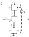
- Fig. 1 shows a schematic illustration of an auxiliary power unit, APU, system 100 based on fuel technology for providing electric power.
- the APU system 100 comprises a fuel reformer 102 which is adapted to produce a hydrogen rich gas 104 from a hydrocarbon fuel 105.
- the hydrogen rich gas 104 is introduced into a fuel cell stack 106 arranged downstream of the fuel reformer 102.
- electric energy 107 is produced by guiding hydrogen to an anode side of a proton electron membrane and an oxidant to a cathode side.
- Excess hydrogen 108, which is not used in the fuel cell stack may then be transferred to a catalytic burner assembly 110, where the excess hydrogen 108 is reacted with air to produce heat 112.
- the heat 112 is then used for producing steam 114 which in turn is used in the fuel reformer 102 for the conversion of hydrocarbon fuel 105 to hydrogen rich gas 108.
- Fig. 2 and Fig. 4 show schematic illustrations of two alternative embodiments of the catalytic burner assembly 110.
- the burner assembly 110 comprises at least two units, namely a burner unit 10 and a mixing unit 20.
- the burner unit 10 comprises a housing 12 defining a reaction chamber 13 in which a catalyst 14 is incorporated. Further the housing 12 comprises a fluid inlet 16 and a fluid outlet 18.
- the mixing unit 20 is arranged in close vicinity to the burning unit 10 and adapted to provide a homogenous mixture of air and hydrogen, which is fed through the fluid inlet 16 into the housing 12 and to the catalyst 14.
- the mixing unit 20 itself comprises a fuel inlet 22 and an oxidant inlet 24, wherein fuel and oxidant are mixed in a mixing chamber 26 and may exit the mixing unit 20 through a fuel-oxidant mixture outlet 28.
- Fig. 2 and 4 further depict that the fuel inlet 22 and the oxidant inlet 24 are angled to a fluid flow direction 30 from the mixing unit 20 to the burner unit 10.
- the mixing unit 20 may be cylindrically shaped having a mantel side 32 and two base plates 34 and 36.
- the cylindrically shape also any other prismatic shape is possible, wherein two base plates 34 and 36 are connected by at least three side surfaces 32.
- the fuel-oxidant-outlet 28 is a pipe-shaped hollow element and its length L extends at least over one of the inlets 22; 24 in the mixing chamber 26.
- the pipe-shaped fuel-oxidant outlet 28 By extending the pipe-shaped fuel-oxidant outlet 28 over at least one of the inlets 22; 24, the risk of oxidant entering the fuel inlet, which may cause uncontrolled combustions, is significantly reduced. Additionally, the fuel inlet may be arranged upstream of the oxidant inlet 24, whereby the risk of uncontrolled combustions is further reduced.
- the pipe-shaped fuel-oxidant outlet 28 further comprises a first opening 28-1 arranged in the mixing chamber 26 and a second opening 28-2 which is provided in a bottom plate 34 of the mixing unit 20. Thereby it should be noted that more than one opening may be provided as first and/or second opening 28-1, 28-2.
- the fuel inlet 22 is arranged upstream of the oxidant inlet 24, whereby an entering of the oxidant into the fuel inlet 22 is avoided. Thereby an unwanted ignition of oxidant and fuel inside the fuel inlet 22 is avoided.
- the fuel-oxidant outlet 28 is not pipe-shaped but designed as simple opening in the bottom plate 34.
- the fuel-oxidant mixture outlet 28 merges with the fluid inlet 16 of the burner unit 10.
- the pipe-shaped fuel-oxidant outlet 28 is elongated, or that a connection pipe is arranged between the burner unit 10 and the mixing unit 20, which fluidly connects the fuel-oxidant-mixture outlet 28 and the fluid inlet 16.
- Fig. 3 and Fig. 5 show detailed spatial views of the mixing unit 20 as shown in Fig. 2 and Fig. 4 , respectively.
- the fuel inlet 22 and the oxidant inlet 24 are arranged at the mantel side 32, wherein the fuel oxidant mixture outlet 28 is arranged at/in the bottom base plate 34.
- the fuel inlet 22 and the oxidant inlet 24 are pipe-shaped providing longitudinal axes A22, A24, whereby a directed fuel stream 38 respectively oxidant stream 40 are provided.
- These directed streams 38 and 40 are deviated by the walls 32 of the mixing unit 20 into a circular motion 41, whereby turbulences are introduced in the reaction chamber 26.
- the mixed gas stream has to undergo a stream redirection from the circular motion the linear motion through the outlet 28, whereby further perturbations may be caused in the fluid streams and the homogeneity of the mixing may even be further improved.
- the pipe-shaped fuel-oxidant outlet 28 intensifies the induced swirling motion and the redirection of the fluid streams, whereby the mixing is enhanced.
- the fuel inlet 22 and the oxidant inlet 24 may be on the same level. Even if an arrangement at the same level is in principle also possible without a pipe-shaped fuel-oxidant-outlet 28, the risk of oxidant entering the fuel pipe 22 increases. In this case, it is therefore preferred to arrange the fuel inlet 22 upstream of the oxidant inlet 24 in order to hinder the oxidant from entering the fuel inlet 22.
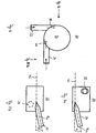
- the fuel inlet 22 and the oxidant inlet 24 are arranged in such a way that the respective fluid streams enter the mixing chamber tangentially as depicted in the top view of Fig. 6 .
- the swirling motion in the chamber 26 and thereby the homogeneity of the mixing may be maximized.
- Fig. 7a and 7b show a further optional detail of the mixing device 20.
- the axes A22, A24 of the fuel inlet pipe 22 respectively the oxidant inlet pipe 24 may be inclined by a predetermined angle
Landscapes
- Engineering & Computer Science (AREA)
- Chemical & Material Sciences (AREA)
- Chemical Kinetics & Catalysis (AREA)
- Combustion & Propulsion (AREA)
- General Engineering & Computer Science (AREA)
- Mechanical Engineering (AREA)
- Life Sciences & Earth Sciences (AREA)
- Manufacturing & Machinery (AREA)
- Sustainable Development (AREA)
- Sustainable Energy (AREA)
- Electrochemistry (AREA)
- General Chemical & Material Sciences (AREA)
- Organic Chemistry (AREA)
- Inorganic Chemistry (AREA)
- General Health & Medical Sciences (AREA)
- Health & Medical Sciences (AREA)
- Hydrogen, Water And Hydrids (AREA)
- Fuel Cell (AREA)
- Gas Burners (AREA)
Description
- The present invention relates to a catalytic burner arrangement as defined in
claim 1, as well as to an auxiliary power assembly based on fuel technology according to the definition of patent claim 8. - In auxiliary power units based on a fuel cell technology, energy is provided by a fuel cell stack. For the operation of the fuel cell usually hydrogen is used. In said APU systems hydrogen is usually produced by so called fuel reformers which generate a hydrogen rich gas from hydrocarbon fuels, like diesel, by means of a catalyst. In some preferred fuel reforming processes, as the autothermal fuel reforming process or the steam reforming process, steam is additionally used for the fuel reforming reaction. The heat required for the production of steam may be provided by use of a catalytic burner arranged downstream of the fuel cell or fuel cell stack, wherein air and excess hydrogen exiting the fuel cell stack are combusted over a catalyst to release energy, which can be used for the steam production.
- The known catalytic burners, as for example disclosed in
US 2008/244974 , have a housing defining a reaction chamber with an inlet for fuel (hydrogen) and an inlet for oxidant (air), whereby fuel and oxidant are introduced into the reaction chamber. The housing further incorporates a catalyst, which is arranged downstream of the inlets, where hydrogen and air catalytically react with each other. The problem of the known catalytic burners is that air and hydrogen often react uncontrolled upstream of the catalyst as soon as being brought in contact with each other. In some cases air may even enter the fuel inlet, whereby such an uncontrolled combustion may also take place in the pipes. However, these uncontrolled combustions may damage the pipes as well as the burner itself. Additionally, often the mixing of air and fuel is inhomogeneous, which in turn results in the development of hotspots in the catalyst, which might damage the catalyst and produce unwanted emissions. - The object of the present invention is therefore to provide a catalytic burner, which hinders ignition of the hydrogen in the pipes and provides a homogenous mixture of air and fuel.
- This object is solved by a catalytic burner according to
patent claim 1, as well as an auxiliary power unit assembly according to patent claim 8. - In the following a catalytic burner arrangement is provided which comprises at least a catalytic burner unit and a mixing unit. Thereby, the catalytic burner unit comprises a housing which defines a reaction chamber in which a catalyst is arranged. The catalyst is adapted to react a fuel, particularly a hydrogen containing fluid with an oxidant, particularly air, for producing heat. The housing further has a fluid inlet for supplying a fluid stream into the housing and a fluid outlet for exiting a fluid stream from the housing.
- The mixing unit in turn forms a mixing chamber in which fuel and oxidant are mixed and comprises a fuel inlet and an oxidant inlet as well as a fuel-oxidant-mixture outlet. The fuel inlet of the catalytic burner unit merges with the fuel-oxidant-outlet of the mixing unit so that the fuel-oxidant-mixture from the mixing chamber may be transported to the reaction chamber of the catalytic burner unit.
- In order to hinder the fuel and the oxidant reacting uncontrolled with each other and providing an improved mixing, said fuel-oxidant-outlet of the mixing chamber is pipe-shaped and extents into the mixing chamber of the mixing unit. By means of the pipe-shaped fuel-oxidant-outlet extending into the mixing chamber, fuel and oxidant are guided in a swirl around the fuel-oxidant-outlet and are forced to stream upwards and to change stream direction before the fuel/oxidant mixture may enter the fuel-oxidant-outlet.
- It should be noted that "pipe-shaped" in the context of the present invention refers to an elongated hollow element, which may have a cylindrical or prismatic form. Said hollow element has at least two openings. At least one first opening allows an entrance of the fuel-oxidant mixture into the hollow element and at least one second opening allows an exit of the fuel-oxidant mixture from the hollow element and thereby from the mixing unit. Thereby, the at least one first opening is arranged inside the mixing chamber. It should be further explicitly noted that more than one opening as first opening and more than one opening as second opening may be provided.
- According to the invention, said fuel inlet of the mixing chamber is arranged upstream of said oxidant inlet. This staggered arrangement of the inlets prevents the oxidant from entering the fuel inlet and thereby prevents an uncontrolled ignition of the fuel. Even if it is preferred to provide in addition a pipe-shaped fuel- oxidant-outlet of the mixing chamber which extends into the mixing chamber of the mixing unit, the staggered arrangement alone also provides an improved mixing and prevents uncontrolled combustion.
- According to a preferred embodiment, a length of the pipe-shaped fuel-oxidant-outlet extents over the oxidant inlet and/or the fuel inlet. Thereby, it may be preferred if the fuel-oxidant-outlet extends over both the oxidant inlet and the fuel inlet. In both embodiments, the swirl and the stream redirection may be maximized.
- According to the invention, the fuel inlet and oxidant inlet are arranged angled to a direction of a main fluid stream streaming through the fuel- oxidant-mixture outlet to the reaction chamber of the catalytic burner. Advantageously, the angled arrangement provides a homogenous mixture as the fluid needs to be redirected from the entrance direction to its exit direction, whereby a mixing of the fluids is performed.
- For having a directed fluid stream of a fuel and oxidant, it is preferred if the fuel inlet and/or the oxidant inlet are designed as at least one pipe having a longitudinal axis, whereby the directed fluid streams are provided.
- According to a further preferred embodiment, said mixing unit is prismaticly or cylindrically shaped having two basis plates and at least three side surfaces or a mantel side, wherein the fuel inlet and the oxidant inlet are arranged in the side surfaces or in the mantel side, and the fuel-oxidant-mixture outlet is arranged at one of the basis plates. Thereby, the geometric design of the mixing unit supports the mixing so that a very homogenous mixture may be provided.
- According to a further preferred embodiment, at least one of the directed fluid streams are offset from a longitudinal axis of the mixing chamber, whereby at least one tangential fluid stream is provided. By means of the tangential fluid streams a homogenous mixture may be achieved.
- According to a further preferred embodiment, the longitudinal axis of the fuel inlet and/or of the oxidant inlet are inclined to a cross sectional plane of the mixing chamber. By the inclined arrangement an uncontrolled ignition of oxidant and fuel and/or an unwanted entering of oxidant into the fuel pipe is avoided.
- According to a further preferred embodiment, the oxidant inlet and the fuel inlet are arranged substantially rectangular to each other, whereby both the mixing is improved and an unwanted ignition is reliably avoided.
- A further aspect of the present invention relates to an auxiliary power assembly based on fuel cell technology which comprises at least a fuel processing assembly which is adapted to convert hydrocarbon fuels into a hydrogen rich gas for fuel cells by using at least hydrocarbon fuel and steam. Downstream of the processor assembly at least one fuel cell or fuel cell stack for providing auxiliary power is arranged. Downstream of the fuel cell a catalytic burner unit is provided which is adapted to burn unused hydrogen exiting from the fuel cell or the fuel cell stack by using an oxidant, such as air or oxygen, and a catalyst for reacting said oxidant and hydrogen to heat, wherein said heat in turn is used for the production of steam used in the fuel processing assembly. Thereby the catalytic burner is designed as described above.
- Further embodiments and preferred arrangements are defined in the description, the figures and the attached claims.
- In the following, the invention will be described by means of embodiments shown in the figures. Thereby, the embodiments are exemplarily only and are not intended to limit the scope of the protection. The scope of protection is solely defined by the attached claims.
- The figures show:
-
Fig. 1 : a schematic illustration of the APU system; -
Fig. 2 : a schematic view of a first preferred embodiment of the catalytic burner; -
Fig. 3 : a schematic detailed spatial view of the mixing unit shown inFig. 2 ; -
Fig. 4 : a schematic view of a second preferred embodiment of the catalytic burner; -
Fig. 5 : a schematic detailed spatial view of the mixing unit shown inFig. 4 ; -
Fig. 6 : a schematic top view of the mixing unit shown inFig. 3 andFig. 5 -
Fig. 7 : schematic side views of the mixing unit ofFig.6 . - In the following same or similarly functioning elements are indicated with the same reference signs.
-
Fig. 1 shows a schematic illustration of an auxiliary power unit, APU,system 100 based on fuel technology for providing electric power. TheAPU system 100 comprises afuel reformer 102 which is adapted to produce a hydrogenrich gas 104 from ahydrocarbon fuel 105. The hydrogenrich gas 104 is introduced into afuel cell stack 106 arranged downstream of thefuel reformer 102. In the fuel cell stackelectric energy 107 is produced by guiding hydrogen to an anode side of a proton electron membrane and an oxidant to a cathode side. Excesshydrogen 108, which is not used in the fuel cell stack may then be transferred to acatalytic burner assembly 110, where theexcess hydrogen 108 is reacted with air to produce heat 112. The heat 112 is then used for producingsteam 114 which in turn is used in thefuel reformer 102 for the conversion ofhydrocarbon fuel 105 to hydrogenrich gas 108. Byproducts from the fuel reforming process and the catalytic burning, such as carbon dioxide and nitrogen oxides, may leave thecatalytic burner 110 asexhaust 116. -
Fig. 2 andFig. 4 show schematic illustrations of two alternative embodiments of thecatalytic burner assembly 110. As can be seen fromFig. 2 and4 , theburner assembly 110 comprises at least two units, namely aburner unit 10 and amixing unit 20. Theburner unit 10 comprises ahousing 12 defining areaction chamber 13 in which acatalyst 14 is incorporated. Further thehousing 12 comprises afluid inlet 16 and afluid outlet 18. The mixingunit 20 is arranged in close vicinity to theburning unit 10 and adapted to provide a homogenous mixture of air and hydrogen, which is fed through thefluid inlet 16 into thehousing 12 and to thecatalyst 14. The mixingunit 20 itself comprises afuel inlet 22 and anoxidant inlet 24, wherein fuel and oxidant are mixed in a mixingchamber 26 and may exit the mixingunit 20 through a fuel-oxidant mixture outlet 28.Fig. 2 and4 further depict that thefuel inlet 22 and theoxidant inlet 24 are angled to afluid flow direction 30 from the mixingunit 20 to theburner unit 10. - Further, the mixing
unit 20 may be cylindrically shaped having amantel side 32 and twobase plates base plates - As can be seen from the first embodiment depicted in
Fig. 2 , the fuel-oxidant-outlet 28 is a pipe-shaped hollow element and its length L extends at least over one of theinlets 22; 24 in the mixingchamber 26. By extending the pipe-shaped fuel-oxidant outlet 28 over at least one of theinlets 22; 24, the risk of oxidant entering the fuel inlet, which may cause uncontrolled combustions, is significantly reduced. Additionally, the fuel inlet may be arranged upstream of theoxidant inlet 24, whereby the risk of uncontrolled combustions is further reduced. The pipe-shaped fuel-oxidant outlet 28 further comprises a first opening 28-1 arranged in the mixingchamber 26 and a second opening 28-2 which is provided in abottom plate 34 of the mixingunit 20. Thereby it should be noted that more than one opening may be provided as first and/or second opening 28-1, 28-2. - As illustrated in the second embodiment shown in
Fig. 4 , thefuel inlet 22 is arranged upstream of theoxidant inlet 24, whereby an entering of the oxidant into thefuel inlet 22 is avoided. Thereby an unwanted ignition of oxidant and fuel inside thefuel inlet 22 is avoided. In contrast to the illustrated embodiment ofFig. 2 , the fuel-oxidant outlet 28 is not pipe-shaped but designed as simple opening in thebottom plate 34. - In both depicted embodiments, the fuel-
oxidant mixture outlet 28 merges with thefluid inlet 16 of theburner unit 10. Of course it is also possible that the pipe-shaped fuel-oxidant outlet 28 is elongated, or that a connection pipe is arranged between theburner unit 10 and the mixingunit 20, which fluidly connects the fuel-oxidant-mixture outlet 28 and thefluid inlet 16. -
Fig. 3 andFig. 5 show detailed spatial views of the mixingunit 20 as shown inFig. 2 andFig. 4 , respectively. As illustrated inFig. 3 andFig. 5 , thefuel inlet 22 and theoxidant inlet 24 are arranged at themantel side 32, wherein the fueloxidant mixture outlet 28 is arranged at/in thebottom base plate 34. Thefuel inlet 22 and theoxidant inlet 24 are pipe-shaped providing longitudinal axes A22, A24, whereby a directedfuel stream 38 respectivelyoxidant stream 40 are provided. These directedstreams walls 32 of the mixingunit 20 into a circular motion 41, whereby turbulences are introduced in thereaction chamber 26. Thereby a mixing of fuel and oxidant is performed. Besides that the mixed gas stream has to undergo a stream redirection from the circular motion the linear motion through theoutlet 28, whereby further perturbations may be caused in the fluid streams and the homogeneity of the mixing may even be further improved. As can be further seen fromFig. 3 , the pipe-shaped fuel-oxidant outlet 28 intensifies the induced swirling motion and the redirection of the fluid streams, whereby the mixing is enhanced. - It should be further noted that in case a pipe-shaped fuel-
oxidant outlet 28 is used, thefuel inlet 22 and theoxidant inlet 24 may be on the same level. Even if an arrangement at the same level is in principle also possible without a pipe-shaped fuel-oxidant-outlet 28, the risk of oxidant entering thefuel pipe 22 increases. In this case, it is therefore preferred to arrange thefuel inlet 22 upstream of theoxidant inlet 24 in order to hinder the oxidant from entering thefuel inlet 22. - For providing an optimal mixing the
fuel inlet 22 and theoxidant inlet 24 are arranged in such a way that the respective fluid streams enter the mixing chamber tangentially as depicted in the top view ofFig. 6 . By the tangential interjection the swirling motion in thechamber 26 and thereby the homogeneity of the mixing may be maximized. -
Fig. 7a and 7b show a further optional detail of the mixingdevice 20. As can be seen from the illustrated side views, the axes A22, A24 of thefuel inlet pipe 22 respectively theoxidant inlet pipe 24 may be inclined by a predetermined angle -
- 100
- auxiliary power unit
- 102
- fuel reformer
- 104
- hydrogen rich gas
- 105
- hydrocarbon fuel
- 106
- fuel cell stack
- 107
- electricity
- 108
- hydrogen
- 110
- catalytic burner
- 112
- heat
- 114
- steam production
- 10
- catalytic burner unit
- 12
- housing
- 14
- catalyst
- 16
- fluid inlet
- 18
- fluid outlet
- 20
- mixing unit
- 22
- fuel inlet
- 24
- oxidant inlet
- 26
- mixing chamber
- 28
- fuel-oxidant mixture outlet 28-1; 28-2 openings
- 30
- fluid stream direction from the mixing chamber to the reaction chamber
- 32
- mantel side
- 34
- bottom base plate
- 36
- top base plate
- 38
- fuel stream direction
- 40
- oxidant stream direction
- 42
- cross sectional plane
- L
- length of fuel-oxidant outlet A22 longitudinal axis of fuel inlet
- A24
- longitudinal axis of oxidant inlet
Claims (8)
- Catalytic burner arrangement (110) comprising at least
a catalytic burner unit (10) with a housing (12) having a reaction chamber (13) in which a catalyst (14) is arranged, wherein the catalyst (14) is adapted to react a fuel, particularly a hydrogen containing fluid, with an oxidant, particularly air, for producing heat, said housing (12) having a fluid inlet (16) for supplying a fluid stream into the housing (12) and a fluid outlet (18) for exiting a fluid stream from the housing (12),
and said catalytic burner arrangement (110) further comprises a mixing unit (20) forming a mixing chamber (26) in which fuel and oxidant are mixed, wherein said mixing unit (20) comprises a fuel inlet (22), an oxidant inlet (24) and a fuel-oxidant- mixture outlet, wherein
the fluid inlet (16) of the catalytic burner unit (10) merges with the fuel-oxidant- outlet (28) of the mixing unit (20) for transferring the fuel-oxidant-mixture from the mixing chamber (26) to the reaction chamber (13) of the catalytic burner unit (10), and
wherein said fuel inlet (22) of the mixing chamber (26) is arranged upstream of said oxidant inlet (24) of the mixing unit (20),
wherein the fuel inlet (22) and the oxidant inlet (24) are arranged angled to a direction (30) of a main fluid stream streaming through the fuel-oxidant-mixture outlet (28) to the reaction chamber (13) of the catalytic burner unit (10). - Catalytic burner arrangement (110) according to claim 1, wherein said mixing chamber has two basis plates (34, 36) which are connected by at least three side surfaces or at least one mantel side (32), wherein said fuel-oxidant-mixture-outlet (28) is arranged at one of the basis plates (34, 36) and said fuel inlet (22) and said oxidant inlet (24) is-are arranged at the side surfaces or the mantel side, and wherein said fuel-oxidant-outlet of the mixing chamber (26) is pipe-shaped and extents into the mixing chamber (26) of the mixing unit (20), wherein preferably a length (L) of the pipe-shaped fuel-oxidant-outlet extents over at least the oxidant inlet (24).
- Catalytic burner arrangement (110) according to any preceding claim, wherein the fuel inlet (22) and/or the oxidant inlet (24) is designed as at least one pipe having a longitudinal axis (A22, A24), whereby a directed fluid stream of fuel (38) and/or oxidant (40) is introduced into the mixing chamber (26).
- Catalytic burner arrangement (110) according to any preceding claim, wherein said mixing chamber (26) is prismaticly or cylindrically shaped, having two basis plates (34; 36) and at least three side surfaces or a mantel side (32), wherein the fuel inlet (22) and the oxidant inlet (24) are arranged at the side surfaces or the mantel side (32), and the fuel-oxidant-mixture outlet (28) is arranged at one of the basis plates (34; 36).
- Catalytic burner arrangement (110) according to claim 3 and 4, wherein the directed fluid streams (38; 40) are offset from a longitudinal axis of the mixing chamber (26), thereby providing at least one tangential fluid stream.
- Catalytic burner arrangement (110) according to any one of the claims 3 to 5, wherein the longitudinal axis of the fuel inlet (22) and/or the oxidant inlet (24) is inclined to a cross sectional plane (42) of the mixing chamber (26).
- Catalytic burner arrangement (110) according to any one of the preceding claims, wherein the oxidant inlet (24) and the fuel inlet (22) are arranged substantially rectangular to each other.
- Auxiliary power assembly (100) based on fuel cell technology comprising at least- at least a catalytic burner arrangement (11) according to any one of the preceeding claims,- a fuel processing assembly (102) which is adapted to convert hydrocarbon fuels (105) into a hydrogen rich gas (104) for fuel cells (106) by using at least hydrocarbon fuel (105) and steam (114);- downstream of the fuel processor assembly (102), at least one fuel cell or fuel cell stack (106) for providing auxiliary power (107); and- downstream of the fuel cell stack (106), the catalytic burner unit (10), being adapted to burn unused hydrogen (108) exiting from the fuel cell or fuel cell stack (106) by using an oxidant and a catalyst (14) for reacting oxidant and hydrogen to heat (112), wherein said heat is used to produce steam (114) used in the fuel processing assembly (102).
Applications Claiming Priority (2)
| Application Number | Priority Date | Filing Date | Title |
|---|---|---|---|
| SE1451477A SE539758C2 (en) | 2014-12-04 | 2014-12-04 | Catalytic burner arrangement |
| PCT/SE2015/051304 WO2016089297A1 (en) | 2014-12-04 | 2015-12-02 | Catalytic burner arrangement |
Publications (2)
| Publication Number | Publication Date |
|---|---|
| EP3227609A1 EP3227609A1 (en) | 2017-10-11 |
| EP3227609B1 true EP3227609B1 (en) | 2020-04-29 |
Family
ID=55405415
Family Applications (2)
| Application Number | Title | Priority Date | Filing Date |
|---|---|---|---|
| EP15837151.8A Active EP3227609B1 (en) | 2014-12-04 | 2015-12-02 | Catalytic burner arrangement |
| EP15837150.0A Not-in-force EP3227608B1 (en) | 2014-12-04 | 2015-12-02 | Catalytic burner arrangement |
Family Applications After (1)
| Application Number | Title | Priority Date | Filing Date |
|---|---|---|---|
| EP15837150.0A Not-in-force EP3227608B1 (en) | 2014-12-04 | 2015-12-02 | Catalytic burner arrangement |
Country Status (8)
| Country | Link |
|---|---|
| US (2) | US10593975B2 (en) |
| EP (2) | EP3227609B1 (en) |
| JP (2) | JP2017538091A (en) |
| KR (3) | KR20170084143A (en) |
| CN (2) | CN107108205B (en) |
| CA (2) | CA2967940C (en) |
| SE (1) | SE539758C2 (en) |
| WO (2) | WO2016089296A1 (en) |
Families Citing this family (5)
| Publication number | Priority date | Publication date | Assignee | Title |
|---|---|---|---|---|
| DE102017001562A1 (en) * | 2017-02-20 | 2018-08-23 | Diehl Aerospace Gmbh | Fuel processor component for a propylene glycol fuel processor and propylene glycol fuel processor |
| KR102438787B1 (en) * | 2018-12-10 | 2022-09-01 | 이코나 파워 인크. | Methods and reactors for making one or more products |
| CN109869717B (en) * | 2019-01-29 | 2020-05-19 | 武汉船用电力推进装置研究所(中国船舶重工集团公司第七一二研究所) | Self-heating hydrogen-oxygen catalytic combustor and self-heating starting method |
| JP7380300B2 (en) * | 2020-02-18 | 2023-11-15 | 株式会社豊田自動織機 | Combustor, reformer and reforming system |
| EP4230250A1 (en) | 2021-04-13 | 2023-08-23 | MT.DERM GmbH | Hand-held microneedling device for local piercing of skin and article |
Family Cites Families (32)
| Publication number | Priority date | Publication date | Assignee | Title |
|---|---|---|---|---|
| GB702035A (en) * | 1948-07-07 | 1954-01-06 | Montedison Spa | Process and apparatus for the production of synthesis-gas from gaseous aliphatic hydrocarbons and oxygen |
| FR2684313B1 (en) * | 1991-12-03 | 1994-01-28 | Institut Francais Petrole | PROCESS AND DEVICE FOR THE MANUFACTURE OF SYNTHESIS GAS AND APPLICATION THEREOF. |
| JP3657675B2 (en) * | 1994-12-06 | 2005-06-08 | 松下電器産業株式会社 | Combustion equipment |
| DE19541914A1 (en) | 1995-11-10 | 1997-05-15 | Asea Brown Boveri | Cooling air cooler for power plants |
| JPH111302A (en) * | 1997-06-10 | 1999-01-06 | Toyota Motor Corp | Fuel reforming method, fuel reforming device, and fuel cell device provided with the fuel reforming device |
| US5988081A (en) | 1997-07-22 | 1999-11-23 | Energy & Environmental Research Corporation | Method and system for the disposal of coal preparation plant waste coal through slurry co-firing in cyclone-fired boilers to effect a reduction in nitrogen oxide emissions |
| US6232005B1 (en) * | 1997-11-20 | 2001-05-15 | General Motors Corporation | Fuel cell system combustor |
| CN100368728C (en) * | 1998-12-18 | 2008-02-13 | 松下电器产业株式会社 | catalytic combustion device |
| JP3531514B2 (en) * | 1999-01-26 | 2004-05-31 | 松下電工株式会社 | Catalytic combustor |
| KR20020030805A (en) | 1999-09-06 | 2002-04-25 | 지스트라텐 알베르터스 빌헬머스 요안느 | Mixing device |
| JP3804436B2 (en) * | 2000-11-10 | 2006-08-02 | 日産自動車株式会社 | Reformer |
| WO2002047805A2 (en) * | 2000-12-15 | 2002-06-20 | Shell Internationale Research Maatschappij B.V. | Catalytic partial oxidation process using a catalyst system having an upstream and a downstream part |
| US6709264B2 (en) * | 2001-11-20 | 2004-03-23 | General Motors Corporation | Catalytic combuster |
| KR20050025678A (en) | 2002-07-25 | 2005-03-14 | 지멘스 악티엔게젤샤프트 | System for cooling cooling air in a gas turbine, and method for cooling cooling air |
| US6712603B2 (en) * | 2002-08-07 | 2004-03-30 | General Motors Corporation | Multiple port catalytic combustion device and method of operating same |
| US7235217B2 (en) | 2003-04-04 | 2007-06-26 | Texaco Inc. | Method and apparatus for rapid heating of fuel reforming reactants |
| JP2005146926A (en) * | 2003-11-12 | 2005-06-09 | Toyota Motor Corp | Fuel reformer |
| US7220513B2 (en) | 2004-03-18 | 2007-05-22 | General Motors Corporation | Balanced humidification in fuel cell proton exchange membranes |
| JP4345661B2 (en) * | 2004-12-21 | 2009-10-14 | トヨタ自動車株式会社 | Catalytic combustor |
| ITMI20052002A1 (en) * | 2005-10-21 | 2007-04-22 | Eni Spa | DEVICE FOR MIXING FLUIDS INSERTED OR COMBINED WITH A REACTOR |
| CN100439798C (en) * | 2005-12-23 | 2008-12-03 | 中国科学院工程热物理研究所 | A gas premixed high-speed burner |
| JP2007255744A (en) * | 2006-03-20 | 2007-10-04 | Mitsubishi Heavy Ind Ltd | Tubular flame burner and fuel reforming device |
| US8557460B2 (en) * | 2007-04-13 | 2013-10-15 | Cool Flame Technologies As | Hydrogen system and method for starting up a hydrogen system |
| EP2067940B2 (en) | 2007-09-07 | 2023-02-15 | General Electric Technology GmbH | Method for operating a combined cycle power plant, and also combined-cycle power plant for carrying out the method |
| DE102008018152B4 (en) | 2008-04-10 | 2019-03-07 | Eberspächer Climate Control Systems GmbH & Co. KG | Fuel cell system and associated operating method |
| EP2140932A1 (en) * | 2008-07-04 | 2010-01-06 | Ammonia Casale S.A. | A process and a reactor for oxidation of a hydrocarbon |
| JP5604038B2 (en) * | 2008-08-25 | 2014-10-08 | 株式会社日立製作所 | Reaction apparatus and reaction plant |
| JP5625257B2 (en) * | 2009-04-13 | 2014-11-19 | いすゞ自動車株式会社 | Exhaust gas temperature riser |
| JP2011027019A (en) * | 2009-07-24 | 2011-02-10 | Yamabiko Corp | Two-cycle engine |
| GB2484254A (en) | 2010-08-04 | 2012-04-11 | Combined Cycle Enhancements Ltd | Gas turbine apparatus with energy recovery heat exchange system |
| SE537092C2 (en) * | 2011-09-08 | 2015-01-07 | Reformtech Heating Holding Ab | Burner |
| CN203803506U (en) * | 2014-03-13 | 2014-09-03 | 张家港市天源机械制造有限公司 | Catalyst regenerating device |
-
2014
- 2014-12-04 SE SE1451477A patent/SE539758C2/en not_active IP Right Cessation
-
2015
- 2015-12-02 EP EP15837151.8A patent/EP3227609B1/en active Active
- 2015-12-02 KR KR1020177015152A patent/KR20170084143A/en not_active Ceased
- 2015-12-02 CN CN201580063647.1A patent/CN107108205B/en not_active Expired - Fee Related
- 2015-12-02 EP EP15837150.0A patent/EP3227608B1/en not_active Not-in-force
- 2015-12-02 CN CN201580063664.5A patent/CN107667070B/en not_active Expired - Fee Related
- 2015-12-02 KR KR1020177015151A patent/KR20170083072A/en not_active Ceased
- 2015-12-02 JP JP2017529806A patent/JP2017538091A/en active Pending
- 2015-12-02 CA CA2967940A patent/CA2967940C/en active Active
- 2015-12-02 WO PCT/SE2015/051303 patent/WO2016089296A1/en not_active Ceased
- 2015-12-02 US US15/528,755 patent/US10593975B2/en active Active
- 2015-12-02 WO PCT/SE2015/051304 patent/WO2016089297A1/en not_active Ceased
- 2015-12-02 US US15/528,756 patent/US10593976B2/en active Active
- 2015-12-02 CA CA2967942A patent/CA2967942C/en active Active
- 2015-12-02 JP JP2017529814A patent/JP6629324B2/en not_active Expired - Fee Related
- 2015-12-02 KR KR1020197036383A patent/KR102093864B1/en active Active
Non-Patent Citations (1)
| Title |
|---|
| None * |
Also Published As
| Publication number | Publication date |
|---|---|
| JP6629324B2 (en) | 2020-01-15 |
| JP2017538091A (en) | 2017-12-21 |
| US10593975B2 (en) | 2020-03-17 |
| JP2017538092A (en) | 2017-12-21 |
| KR102093864B1 (en) | 2020-03-26 |
| CN107108205A (en) | 2017-08-29 |
| EP3227608B1 (en) | 2018-09-26 |
| CN107667070B (en) | 2020-12-25 |
| CA2967942C (en) | 2019-07-09 |
| SE1451477A1 (en) | 2016-06-05 |
| KR20170083072A (en) | 2017-07-17 |
| KR20170084143A (en) | 2017-07-19 |
| CA2967942A1 (en) | 2016-06-09 |
| CN107108205B (en) | 2019-07-16 |
| EP3227608A1 (en) | 2017-10-11 |
| WO2016089297A1 (en) | 2016-06-09 |
| CA2967940C (en) | 2019-07-09 |
| CN107667070A (en) | 2018-02-06 |
| EP3227609A1 (en) | 2017-10-11 |
| KR20190139342A (en) | 2019-12-17 |
| US20170358810A1 (en) | 2017-12-14 |
| US20170365869A1 (en) | 2017-12-21 |
| SE539758C2 (en) | 2017-11-21 |
| WO2016089296A1 (en) | 2016-06-09 |
| CA2967940A1 (en) | 2016-06-09 |
| HK1246264A1 (en) | 2018-09-07 |
| US10593976B2 (en) | 2020-03-17 |
Similar Documents
| Publication | Publication Date | Title |
|---|---|---|
| US10122027B2 (en) | High-temperature operating fuel-cell module | |
| EP3136487B1 (en) | Hydrogen generating apparatus and fuel cell system | |
| EP3227608B1 (en) | Catalytic burner arrangement | |
| EP2810329B1 (en) | Fuel cell module | |
| EP3022791B1 (en) | Fuel cell module | |
| US10651487B2 (en) | Modular apparatus of fuel cell system | |
| EP3022790B1 (en) | Fuel cell module | |
| HK1245381B (en) | Catalytic burner arrangement | |
| HK1245381A1 (en) | Catalytic burner arrangement | |
| KR101576713B1 (en) | Pre-mixed combustion burner for fuel cell | |
| HK1246264B (en) | Catalytic burner arrangement | |
| US20140102667A1 (en) | Combined heat exchanging and fluid mixing apparatus |
Legal Events
| Date | Code | Title | Description |
|---|---|---|---|
| STAA | Information on the status of an ep patent application or granted ep patent |
Free format text: STATUS: THE INTERNATIONAL PUBLICATION HAS BEEN MADE |
|
| PUAI | Public reference made under article 153(3) epc to a published international application that has entered the european phase |
Free format text: ORIGINAL CODE: 0009012 |
|
| STAA | Information on the status of an ep patent application or granted ep patent |
Free format text: STATUS: REQUEST FOR EXAMINATION WAS MADE |
|
| 17P | Request for examination filed |
Effective date: 20170601 |
|
| AK | Designated contracting states |
Kind code of ref document: A1 Designated state(s): AL AT BE BG CH CY CZ DE DK EE ES FI FR GB GR HR HU IE IS IT LI LT LU LV MC MK MT NL NO PL PT RO RS SE SI SK SM TR |
|
| AX | Request for extension of the european patent |
Extension state: BA ME |
|
| DAV | Request for validation of the european patent (deleted) | ||
| DAX | Request for extension of the european patent (deleted) | ||
| REG | Reference to a national code |
Ref country code: HK Ref legal event code: DE Ref document number: 1245381 Country of ref document: HK |
|
| GRAP | Despatch of communication of intention to grant a patent |
Free format text: ORIGINAL CODE: EPIDOSNIGR1 |
|
| STAA | Information on the status of an ep patent application or granted ep patent |
Free format text: STATUS: GRANT OF PATENT IS INTENDED |
|
| INTG | Intention to grant announced |
Effective date: 20191007 |
|
| GRAJ | Information related to disapproval of communication of intention to grant by the applicant or resumption of examination proceedings by the epo deleted |
Free format text: ORIGINAL CODE: EPIDOSDIGR1 |
|
| STAA | Information on the status of an ep patent application or granted ep patent |
Free format text: STATUS: REQUEST FOR EXAMINATION WAS MADE |
|
| GRAP | Despatch of communication of intention to grant a patent |
Free format text: ORIGINAL CODE: EPIDOSNIGR1 |
|
| STAA | Information on the status of an ep patent application or granted ep patent |
Free format text: STATUS: GRANT OF PATENT IS INTENDED |
|
| INTG | Intention to grant announced |
Effective date: 20191127 |
|
| GRAS | Grant fee paid |
Free format text: ORIGINAL CODE: EPIDOSNIGR3 |
|
| GRAA | (expected) grant |
Free format text: ORIGINAL CODE: 0009210 |
|
| STAA | Information on the status of an ep patent application or granted ep patent |
Free format text: STATUS: THE PATENT HAS BEEN GRANTED |
|
| AK | Designated contracting states |
Kind code of ref document: B1 Designated state(s): AL AT BE BG CH CY CZ DE DK EE ES FI FR GB GR HR HU IE IS IT LI LT LU LV MC MK MT NL NO PL PT RO RS SE SI SK SM TR |
|
| REG | Reference to a national code |
Ref country code: GB Ref legal event code: FG4D |
|
| REG | Reference to a national code |
Ref country code: CH Ref legal event code: EP |
|
| REG | Reference to a national code |
Ref country code: AT Ref legal event code: REF Ref document number: 1263884 Country of ref document: AT Kind code of ref document: T Effective date: 20200515 |
|
| REG | Reference to a national code |
Ref country code: DE Ref legal event code: R096 Ref document number: 602015051845 Country of ref document: DE |
|
| REG | Reference to a national code |
Ref country code: IE Ref legal event code: FG4D |
|
| REG | Reference to a national code |
Ref country code: SE Ref legal event code: TRGR |
|
| REG | Reference to a national code |
Ref country code: NL Ref legal event code: MP Effective date: 20200429 |
|
| REG | Reference to a national code |
Ref country code: LT Ref legal event code: MG4D |
|
| PG25 | Lapsed in a contracting state [announced via postgrant information from national office to epo] |
Ref country code: NO Free format text: LAPSE BECAUSE OF FAILURE TO SUBMIT A TRANSLATION OF THE DESCRIPTION OR TO PAY THE FEE WITHIN THE PRESCRIBED TIME-LIMIT Effective date: 20200729 Ref country code: IS Free format text: LAPSE BECAUSE OF FAILURE TO SUBMIT A TRANSLATION OF THE DESCRIPTION OR TO PAY THE FEE WITHIN THE PRESCRIBED TIME-LIMIT Effective date: 20200829 Ref country code: PT Free format text: LAPSE BECAUSE OF FAILURE TO SUBMIT A TRANSLATION OF THE DESCRIPTION OR TO PAY THE FEE WITHIN THE PRESCRIBED TIME-LIMIT Effective date: 20200831 Ref country code: GR Free format text: LAPSE BECAUSE OF FAILURE TO SUBMIT A TRANSLATION OF THE DESCRIPTION OR TO PAY THE FEE WITHIN THE PRESCRIBED TIME-LIMIT Effective date: 20200730 Ref country code: FI Free format text: LAPSE BECAUSE OF FAILURE TO SUBMIT A TRANSLATION OF THE DESCRIPTION OR TO PAY THE FEE WITHIN THE PRESCRIBED TIME-LIMIT Effective date: 20200429 Ref country code: LT Free format text: LAPSE BECAUSE OF FAILURE TO SUBMIT A TRANSLATION OF THE DESCRIPTION OR TO PAY THE FEE WITHIN THE PRESCRIBED TIME-LIMIT Effective date: 20200429 |
|
| REG | Reference to a national code |
Ref country code: AT Ref legal event code: MK05 Ref document number: 1263884 Country of ref document: AT Kind code of ref document: T Effective date: 20200429 |
|
| PG25 | Lapsed in a contracting state [announced via postgrant information from national office to epo] |
Ref country code: HR Free format text: LAPSE BECAUSE OF FAILURE TO SUBMIT A TRANSLATION OF THE DESCRIPTION OR TO PAY THE FEE WITHIN THE PRESCRIBED TIME-LIMIT Effective date: 20200429 Ref country code: RS Free format text: LAPSE BECAUSE OF FAILURE TO SUBMIT A TRANSLATION OF THE DESCRIPTION OR TO PAY THE FEE WITHIN THE PRESCRIBED TIME-LIMIT Effective date: 20200429 Ref country code: BG Free format text: LAPSE BECAUSE OF FAILURE TO SUBMIT A TRANSLATION OF THE DESCRIPTION OR TO PAY THE FEE WITHIN THE PRESCRIBED TIME-LIMIT Effective date: 20200729 Ref country code: LV Free format text: LAPSE BECAUSE OF FAILURE TO SUBMIT A TRANSLATION OF THE DESCRIPTION OR TO PAY THE FEE WITHIN THE PRESCRIBED TIME-LIMIT Effective date: 20200429 |
|
| PG25 | Lapsed in a contracting state [announced via postgrant information from national office to epo] |
Ref country code: AL Free format text: LAPSE BECAUSE OF FAILURE TO SUBMIT A TRANSLATION OF THE DESCRIPTION OR TO PAY THE FEE WITHIN THE PRESCRIBED TIME-LIMIT Effective date: 20200429 Ref country code: NL Free format text: LAPSE BECAUSE OF FAILURE TO SUBMIT A TRANSLATION OF THE DESCRIPTION OR TO PAY THE FEE WITHIN THE PRESCRIBED TIME-LIMIT Effective date: 20200429 |
|
| PG25 | Lapsed in a contracting state [announced via postgrant information from national office to epo] |
Ref country code: ES Free format text: LAPSE BECAUSE OF FAILURE TO SUBMIT A TRANSLATION OF THE DESCRIPTION OR TO PAY THE FEE WITHIN THE PRESCRIBED TIME-LIMIT Effective date: 20200429 Ref country code: DK Free format text: LAPSE BECAUSE OF FAILURE TO SUBMIT A TRANSLATION OF THE DESCRIPTION OR TO PAY THE FEE WITHIN THE PRESCRIBED TIME-LIMIT Effective date: 20200429 Ref country code: SM Free format text: LAPSE BECAUSE OF FAILURE TO SUBMIT A TRANSLATION OF THE DESCRIPTION OR TO PAY THE FEE WITHIN THE PRESCRIBED TIME-LIMIT Effective date: 20200429 Ref country code: EE Free format text: LAPSE BECAUSE OF FAILURE TO SUBMIT A TRANSLATION OF THE DESCRIPTION OR TO PAY THE FEE WITHIN THE PRESCRIBED TIME-LIMIT Effective date: 20200429 Ref country code: AT Free format text: LAPSE BECAUSE OF FAILURE TO SUBMIT A TRANSLATION OF THE DESCRIPTION OR TO PAY THE FEE WITHIN THE PRESCRIBED TIME-LIMIT Effective date: 20200429 Ref country code: IT Free format text: LAPSE BECAUSE OF FAILURE TO SUBMIT A TRANSLATION OF THE DESCRIPTION OR TO PAY THE FEE WITHIN THE PRESCRIBED TIME-LIMIT Effective date: 20200429 Ref country code: CZ Free format text: LAPSE BECAUSE OF FAILURE TO SUBMIT A TRANSLATION OF THE DESCRIPTION OR TO PAY THE FEE WITHIN THE PRESCRIBED TIME-LIMIT Effective date: 20200429 Ref country code: RO Free format text: LAPSE BECAUSE OF FAILURE TO SUBMIT A TRANSLATION OF THE DESCRIPTION OR TO PAY THE FEE WITHIN THE PRESCRIBED TIME-LIMIT Effective date: 20200429 |
|
| REG | Reference to a national code |
Ref country code: DE Ref legal event code: R097 Ref document number: 602015051845 Country of ref document: DE |
|
| PG25 | Lapsed in a contracting state [announced via postgrant information from national office to epo] |
Ref country code: PL Free format text: LAPSE BECAUSE OF FAILURE TO SUBMIT A TRANSLATION OF THE DESCRIPTION OR TO PAY THE FEE WITHIN THE PRESCRIBED TIME-LIMIT Effective date: 20200429 Ref country code: SK Free format text: LAPSE BECAUSE OF FAILURE TO SUBMIT A TRANSLATION OF THE DESCRIPTION OR TO PAY THE FEE WITHIN THE PRESCRIBED TIME-LIMIT Effective date: 20200429 |
|
| PLBE | No opposition filed within time limit |
Free format text: ORIGINAL CODE: 0009261 |
|
| STAA | Information on the status of an ep patent application or granted ep patent |
Free format text: STATUS: NO OPPOSITION FILED WITHIN TIME LIMIT |
|
| 26N | No opposition filed |
Effective date: 20210201 |
|
| PG25 | Lapsed in a contracting state [announced via postgrant information from national office to epo] |
Ref country code: SI Free format text: LAPSE BECAUSE OF FAILURE TO SUBMIT A TRANSLATION OF THE DESCRIPTION OR TO PAY THE FEE WITHIN THE PRESCRIBED TIME-LIMIT Effective date: 20200429 |
|
| REG | Reference to a national code |
Ref country code: CH Ref legal event code: PL |
|
| PG25 | Lapsed in a contracting state [announced via postgrant information from national office to epo] |
Ref country code: MC Free format text: LAPSE BECAUSE OF FAILURE TO SUBMIT A TRANSLATION OF THE DESCRIPTION OR TO PAY THE FEE WITHIN THE PRESCRIBED TIME-LIMIT Effective date: 20200429 |
|
| REG | Reference to a national code |
Ref country code: BE Ref legal event code: MM Effective date: 20201231 |
|
| PG25 | Lapsed in a contracting state [announced via postgrant information from national office to epo] |
Ref country code: IE Free format text: LAPSE BECAUSE OF NON-PAYMENT OF DUE FEES Effective date: 20201202 Ref country code: LU Free format text: LAPSE BECAUSE OF NON-PAYMENT OF DUE FEES Effective date: 20201202 |
|
| PG25 | Lapsed in a contracting state [announced via postgrant information from national office to epo] |
Ref country code: LI Free format text: LAPSE BECAUSE OF NON-PAYMENT OF DUE FEES Effective date: 20201231 Ref country code: CH Free format text: LAPSE BECAUSE OF NON-PAYMENT OF DUE FEES Effective date: 20201231 |
|
| PG25 | Lapsed in a contracting state [announced via postgrant information from national office to epo] |
Ref country code: TR Free format text: LAPSE BECAUSE OF FAILURE TO SUBMIT A TRANSLATION OF THE DESCRIPTION OR TO PAY THE FEE WITHIN THE PRESCRIBED TIME-LIMIT Effective date: 20200429 Ref country code: MT Free format text: LAPSE BECAUSE OF FAILURE TO SUBMIT A TRANSLATION OF THE DESCRIPTION OR TO PAY THE FEE WITHIN THE PRESCRIBED TIME-LIMIT Effective date: 20200429 Ref country code: CY Free format text: LAPSE BECAUSE OF FAILURE TO SUBMIT A TRANSLATION OF THE DESCRIPTION OR TO PAY THE FEE WITHIN THE PRESCRIBED TIME-LIMIT Effective date: 20200429 |
|
| PG25 | Lapsed in a contracting state [announced via postgrant information from national office to epo] |
Ref country code: MK Free format text: LAPSE BECAUSE OF FAILURE TO SUBMIT A TRANSLATION OF THE DESCRIPTION OR TO PAY THE FEE WITHIN THE PRESCRIBED TIME-LIMIT Effective date: 20200429 |
|
| PG25 | Lapsed in a contracting state [announced via postgrant information from national office to epo] |
Ref country code: BE Free format text: LAPSE BECAUSE OF NON-PAYMENT OF DUE FEES Effective date: 20201231 |
|
| P01 | Opt-out of the competence of the unified patent court (upc) registered |
Effective date: 20230513 |
|
| P02 | Opt-out of the competence of the unified patent court (upc) changed |
Effective date: 20230516 |
|
| PGFP | Annual fee paid to national office [announced via postgrant information from national office to epo] |
Ref country code: GB Payment date: 20231220 Year of fee payment: 9 |
|
| PGFP | Annual fee paid to national office [announced via postgrant information from national office to epo] |
Ref country code: SE Payment date: 20231219 Year of fee payment: 9 Ref country code: FR Payment date: 20231220 Year of fee payment: 9 Ref country code: DE Payment date: 20231214 Year of fee payment: 9 |
|
| REG | Reference to a national code |
Ref country code: DE Ref legal event code: R119 Ref document number: 602015051845 Country of ref document: DE |
|
| REG | Reference to a national code |
Ref country code: SE Ref legal event code: EUG |
|
| GBPC | Gb: european patent ceased through non-payment of renewal fee |
Effective date: 20241202 |
|
| PG25 | Lapsed in a contracting state [announced via postgrant information from national office to epo] |
Ref country code: DE Free format text: LAPSE BECAUSE OF NON-PAYMENT OF DUE FEES Effective date: 20250701 |
|
| PG25 | Lapsed in a contracting state [announced via postgrant information from national office to epo] |
Ref country code: GB Free format text: LAPSE BECAUSE OF NON-PAYMENT OF DUE FEES Effective date: 20241202 |
|
| PG25 | Lapsed in a contracting state [announced via postgrant information from national office to epo] |
Ref country code: FR Free format text: LAPSE BECAUSE OF NON-PAYMENT OF DUE FEES Effective date: 20241231 |