EP3227564B1 - Plunger pressure accumulator - Google Patents
Plunger pressure accumulator Download PDFInfo
- Publication number
- EP3227564B1 EP3227564B1 EP15820876.9A EP15820876A EP3227564B1 EP 3227564 B1 EP3227564 B1 EP 3227564B1 EP 15820876 A EP15820876 A EP 15820876A EP 3227564 B1 EP3227564 B1 EP 3227564B1
- Authority
- EP
- European Patent Office
- Prior art keywords
- plunger
- pressure accumulator
- subspace
- shell
- regenerator
- Prior art date
- Legal status (The legal status is an assumption and is not a legal conclusion. Google has not performed a legal analysis and makes no representation as to the accuracy of the status listed.)
- Active
Links
Images


Classifications
-
- F—MECHANICAL ENGINEERING; LIGHTING; HEATING; WEAPONS; BLASTING
- F15—FLUID-PRESSURE ACTUATORS; HYDRAULICS OR PNEUMATICS IN GENERAL
- F15B—SYSTEMS ACTING BY MEANS OF FLUIDS IN GENERAL; FLUID-PRESSURE ACTUATORS, e.g. SERVOMOTORS; DETAILS OF FLUID-PRESSURE SYSTEMS, NOT OTHERWISE PROVIDED FOR
- F15B1/00—Installations or systems with accumulators; Supply reservoir or sump assemblies
-
- F—MECHANICAL ENGINEERING; LIGHTING; HEATING; WEAPONS; BLASTING
- F15—FLUID-PRESSURE ACTUATORS; HYDRAULICS OR PNEUMATICS IN GENERAL
- F15B—SYSTEMS ACTING BY MEANS OF FLUIDS IN GENERAL; FLUID-PRESSURE ACTUATORS, e.g. SERVOMOTORS; DETAILS OF FLUID-PRESSURE SYSTEMS, NOT OTHERWISE PROVIDED FOR
- F15B1/00—Installations or systems with accumulators; Supply reservoir or sump assemblies
- F15B1/02—Installations or systems with accumulators
- F15B1/04—Accumulators
- F15B1/08—Accumulators using a gas cushion; Gas charging devices; Indicators or floats therefor
- F15B1/086—Accumulators using a gas cushion; Gas charging devices; Indicators or floats therefor the gas cushion being entirely enclosed by the separating means, e.g. foam or gas-filled balls
-
- F—MECHANICAL ENGINEERING; LIGHTING; HEATING; WEAPONS; BLASTING
- F15—FLUID-PRESSURE ACTUATORS; HYDRAULICS OR PNEUMATICS IN GENERAL
- F15B—SYSTEMS ACTING BY MEANS OF FLUIDS IN GENERAL; FLUID-PRESSURE ACTUATORS, e.g. SERVOMOTORS; DETAILS OF FLUID-PRESSURE SYSTEMS, NOT OTHERWISE PROVIDED FOR
- F15B1/00—Installations or systems with accumulators; Supply reservoir or sump assemblies
- F15B1/02—Installations or systems with accumulators
- F15B1/04—Accumulators
- F15B1/08—Accumulators using a gas cushion; Gas charging devices; Indicators or floats therefor
- F15B1/24—Accumulators using a gas cushion; Gas charging devices; Indicators or floats therefor with rigid separating means, e.g. pistons
-
- F—MECHANICAL ENGINEERING; LIGHTING; HEATING; WEAPONS; BLASTING
- F15—FLUID-PRESSURE ACTUATORS; HYDRAULICS OR PNEUMATICS IN GENERAL
- F15B—SYSTEMS ACTING BY MEANS OF FLUIDS IN GENERAL; FLUID-PRESSURE ACTUATORS, e.g. SERVOMOTORS; DETAILS OF FLUID-PRESSURE SYSTEMS, NOT OTHERWISE PROVIDED FOR
- F15B21/00—Common features of fluid actuator systems; Fluid-pressure actuator systems or details thereof, not covered by any other group of this subclass
- F15B21/14—Energy-recuperation means
-
- F—MECHANICAL ENGINEERING; LIGHTING; HEATING; WEAPONS; BLASTING
- F15—FLUID-PRESSURE ACTUATORS; HYDRAULICS OR PNEUMATICS IN GENERAL
- F15B—SYSTEMS ACTING BY MEANS OF FLUIDS IN GENERAL; FLUID-PRESSURE ACTUATORS, e.g. SERVOMOTORS; DETAILS OF FLUID-PRESSURE SYSTEMS, NOT OTHERWISE PROVIDED FOR
- F15B2201/00—Accumulators
- F15B2201/20—Accumulator cushioning means
- F15B2201/205—Accumulator cushioning means using gas
-
- F—MECHANICAL ENGINEERING; LIGHTING; HEATING; WEAPONS; BLASTING
- F15—FLUID-PRESSURE ACTUATORS; HYDRAULICS OR PNEUMATICS IN GENERAL
- F15B—SYSTEMS ACTING BY MEANS OF FLUIDS IN GENERAL; FLUID-PRESSURE ACTUATORS, e.g. SERVOMOTORS; DETAILS OF FLUID-PRESSURE SYSTEMS, NOT OTHERWISE PROVIDED FOR
- F15B2201/00—Accumulators
- F15B2201/30—Accumulator separating means
- F15B2201/31—Accumulator separating means having rigid separating means, e.g. pistons
-
- F—MECHANICAL ENGINEERING; LIGHTING; HEATING; WEAPONS; BLASTING
- F15—FLUID-PRESSURE ACTUATORS; HYDRAULICS OR PNEUMATICS IN GENERAL
- F15B—SYSTEMS ACTING BY MEANS OF FLUIDS IN GENERAL; FLUID-PRESSURE ACTUATORS, e.g. SERVOMOTORS; DETAILS OF FLUID-PRESSURE SYSTEMS, NOT OTHERWISE PROVIDED FOR
- F15B2201/00—Accumulators
- F15B2201/30—Accumulator separating means
- F15B2201/32—Accumulator separating means having multiple separating means, e.g. with an auxiliary piston sliding within a main piston, multiple membranes or combinations thereof
-
- F—MECHANICAL ENGINEERING; LIGHTING; HEATING; WEAPONS; BLASTING
- F15—FLUID-PRESSURE ACTUATORS; HYDRAULICS OR PNEUMATICS IN GENERAL
- F15B—SYSTEMS ACTING BY MEANS OF FLUIDS IN GENERAL; FLUID-PRESSURE ACTUATORS, e.g. SERVOMOTORS; DETAILS OF FLUID-PRESSURE SYSTEMS, NOT OTHERWISE PROVIDED FOR
- F15B2201/00—Accumulators
- F15B2201/40—Constructional details of accumulators not otherwise provided for
- F15B2201/42—Heat recuperators for isothermal compression and expansion
Definitions
- the invention relates to a plunger pressure accumulator, comprising: a shell with an interior space defined by its walls; a plunger which is adapted to move in a longitudinal direction of the shell into the interior space of the shell; said space being divided into at least two subspaces, the first subspace of which is suppliable with the hydraulic fluid of an external system and the second subspace is provided with a pressurized gas.
- Pressure accumulators are typically used as a part of the energy recovery system in some hydraulic system to improve the hydraulic system's overall efficiency. Hydraulic energy is stored in a pressure accumulator by using a hydraulic fluid of the hydraulic system to compress the pressure accumulator's gas present in one subspace. In a compression phase, the gas temperature rises.
- Operation of the diaphragm and bladder accumulator is based on the deformation of a diaphragm or bladder between the spaces, allowing in the compression phase a reduction of the second subspace volume (compression of the gas). These are employed typically for the equalization of pressure fluctuations in hydraulic systems.
- the piston accumulator includes a piston, which is capable of sliding in contact with an internal surface of the shell in response to a force generated by a hydraulic fluid, and which also divides an interior space of the shell into two aforesaid subspaces.
- Typical accumulators are known from WO 2010/134840 A1 .
- the piston is also provided with bellows, which operate as a vibration damper and which, due to the design and location thereof (in a direct contact with hydraulic fluid), adversely transfer heat from the gas directly to the hydraulic fluid of the first subspace and further into the environment.
- bellows Such a structure, in which a complicated compressible regenerator is in contact with and in motion relative to many elements, such the shell, the piston, and the deforming insulator, is susceptible to damage. In addition, this imposes high quality requirements on the entire internal surface of a shell and on the external surface of a piston, which in turn increases manufacturing costs.
- An objective of the present invention is to provide a plunger pressure accumulator, in which the aforesaid drawbacks can be eliminated or at least substantially alleviated.
- An objective of the invention is to provide a plunger pressure accumulator, wherein, with a structure more cost efficient than before, it is possible to maintain the heat generated in one of the subspaces and to release it at a correct moment, for example in a discharge phase.
- the aforesaid objective of the invention is attained according to the invention in such a way that in the interior space of the shell between the plunger and the shell is arranged a slide bearing element upon which the plunger is supported to move to a distance apart from an internal surface of the first subspace and from an internal surface of the second subspace, that the plunger pressure accumulator is provided with at least one regenerator which is stationary relative to the shell or the plunger as the plunger moves, and in that between the plunger (3) and the shell (2) is provided a sealing element (2c) producing a sealing effect, which, together with the plunger (3), divides the space in a longitudinal direction of the shell (2) into the first subspace (4) and the second subspace (5).
- plunger pressure accumulator a construction simpler than before enables one of the subspaces (the shell) as well as the plunger to be provided with a regenerator, for example between the movable plunger and an internal surface of the shell, as the plunger is discrete (not in contact with) from the shell.
- a regenerator for example between the movable plunger and an internal surface of the shell, as the plunger is discrete (not in contact with) from the shell.
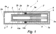
- the plunger pressure accumulator 1 comprises an elongated shell 2 with an interior space defined by its walls. The space is provided with a plunger having its body denoted with reference numeral 3.
- the plunger 3 is an elongated hollow sleeve type element with a closed first end.
- the plunger is annular in its cross-section, but the shape is not necessarily limited to that.
- the cross-section can also be for example a square or rectangle.
- the shell 2 can have a correspondingly deviant cross-sectional shape.
- a slide element 2b of the invention Between the plunger 3 and the shell 2 is provided a slide element 2b of the invention, upon which the plunger 3 is supported to move in a space. Therefore, the structure of a plunger pressure accumulator 1 shown in fig. 1 indeed comprises a plunger as far as its piston is concerned.
- the slide element may consist of one or more annular slide bearing elements 2b disposed successively in a longitudinal direction of the shell. In this case, the slide element 2b is made stationary relative to the shell 2, but it can also be made stationary relative to the plunger 3.
- Fig. 1 presents two slide bearing elements.
- a sealing element 2c or some other element which establishes a sealing effect and, together with the plunger 3, divides the space in a lengthwise direction of the shell 2 into two subspaces 4 and 5.
- the sealing element 2c is made stationary relative to the shell 2, thereby leaving the sealing surface in engagement with an external surface 3' of the plunger 3.
- the first subspace 4 is suppliable with a hydraulic fluid by way of a port 2a provided in connection with the shell 2.
- the source of hydraulic fluid is typically some external system, including a hydraulic circuit that the plunger pressure accumulator 3 is in communication with.
- the second subspace 5 is provided with a pressurized gas.
- the space inside the walls of the hollow plunger 3 establishes a third subspace 6 which is in communication with the second subspace 5.
- the third subspace 6 also contains pressurized gas at a pressure equal to that of the second subspace 5.
- the pressurized gas consists of a compressible gas. This compression takes place as the first subspace 4 is supplied with an incompressible or substantially incompressible hydraulic fluid from an external system.
- the plunger 3 comprises a first insulating layer, which is denoted with reference numeral 10a.
- the first insulating layer 10a is preferably disposed in engagement with an inner surface of the walls of the plunger 3 so as to cover the entire internal surface of the plunger 3.
- the plunger pressure accumulator 3 is provided with at least one regenerator, which is stationary relative to the shell 2 or the plunger 3.
- Fig. 1 shows two regenerators 7a and 7b, which can be alternatives to each other or which can be applied concurrently in the plunger pressure accumulator 3 of the invention. It should be noted that these are merely examples of regenerator configurations, nor is the invention limited to these configurations and positions.
- the regenerator 7a presents one solution for a type of regenerator which is stationary relative to the shell 2.
- the elongated regenerator 7a is attached to an end face of the shell 2 and adapted to extend a distance into the third subspace 6.
- the first insulating layer 10a provided on the plunger 3 surrounds the regenerator 7a at least partially.
- the regenerator 7a and/or the plunger 3 can also be designed in terms of its length so as to be surrounded by the insulating layer 10a only in a compression phase, i.e. as the piston 3 is being displaced by hydraulic pressure (to the right in fig. 1 ).
- the structure and/or material of the regenerator 7a is such that the pressurized gas present in the third subspace 6 is able to flow into the regenerator 7a and, if necessary, through the regenerator 7a into the second subspace 5.
- the plunger pressure accumulator 1 may include a regenerator 7b which is stationary relative to the plunger 3.
- Fig. 1 shows a regenerator 7b, which has a cavity type structure and which is disposed in engagement with the insulating layer 10a so as to have the first insulating layer 10a completely covered by the regenerator 7b.
- the regenerator 7a if present, which is stationary relative the shell 2, has moved into a cavity of the regenerator 7b which is stationary relative to the plunger 3.
- it is the cavity of the regenerator 7b which establishes the third subspace 6.
- the insulator layer 10a of the plunger 3 can be alternatively omitted and optionally replaced for example with a thicker layer of regenerator material, whereby the regenerator 7b will have a greater mass and heat capacity.
- the internal surface of the shell 2 defined by the second subspace 5 is provided with a second insulating layer 10b.
- This can be implemented in such a way that the second insulating layer 10b is attached to the shell 2 in a manner making it stationary relative to the shell 2.
- This is made possible in a particularly advantageous way by having the plunger 3 supported to move with the assistance of the slide elements 2b to a distance apart from an internal surface 4a of the first subspace 4 and from an internal surface 5a of the second subspace 5.
- FIG. 1 What can be further seen in fig. 1 is one further embodiment for a second regenerator, which is stationary relative to the shell 2.
- the second regenerator is denoted with reference numeral 8, and it is in this case constructed as a layer of desired thickness around the insulating layer 10b.
- the second insulating layer 10b is not an absolute necessity, which is why the second regenerator 8 can be optionally disposed in a direct engagement with the internal surface 5a of the second subspace 5 of the shell 2. This is made possible by having the plunger 3 supported to move, according to the invention, with the assistance of the slide elements 2b to a distance apart from the internal surface 4a of the first subspace 4 and from the internal surface 5a of the second subspace 5.
- the plunger type structure of a plunger pressure accumulator enables the use of diverse materials in regenerators.
- the employed material can be for example a metal, ceramic, composite and/or polymer. It is also possible to use a material, such as paraffin, based on phase transition.
- the structure of regenerators can be preferably sintered, mesh-like, fibrous, granular and/or foamy. The implementation of structurally other types of regenerators is possible. The purpose of such structures is to provide an interior space of the shell 2, especially the second subspace 5, at desired locations, with a regenerator sufficient in terms of its thermal capacity, but also in terms of its heat transfer capacity.
- the regenerator which is in communication with a gas of the second subspace 5, as well as with a gas of the third subspace 6, must have an area which is large in comparison with that of the second subspace's internal surface 5a.
- An objective is to collect from the gas as thoroughly as possible the heat generated during the compression phase and to deliver it back into the gas during a discharge phase or expansion phase.
- an effective blockage of heat flows towards the shell by binding the heat as well as by using its appropriate structure and materials for impeding and stopping the flow of heat into the shell structure.
- This objective is attained particularly well with a plunger pressure accumulator construction of the invention, since the plunger 3 does not hinder the positioning of regenerators particularly in the second subspace 5.
- regenerator Depending on the material and structure of a regenerator or regenerators, there will be achieved for the regenerator a surface area which is approximately 10 to 1000-fold compared to the internal surface 5a while the thermal capacity of the regenerator or regenerators is nevertheless sufficient for the recovery of heat generated in the gas.
- the regenerator's surface area with respect to the internal surface 5a can be other than this.
- the regenerator 7a; 7b; 8 also works as an element which delivers the heat stored therein as desired.
- the regenerator or heat transfer device allows the thermal energy, stored in the regenerator 7a; 7b; 8 in the compression phase of pressurized gas, to be released at the latest when the plunger pressure accumulator 1 terminates its discharge phase.
- the duration of a discharge phase is 1-60 seconds but, depending on the application and the plunger pressure accumulator's capacity, it may deviate from the aforesaid time frame, being for example 0,5-600 seconds.
- the regenerator or heat transfer device can be constructed so as to deliver thermal energy even after the discharge phase has terminated.
- fig. 1 In fig. 1 is shown an elongated plunger, whose length parallel to the direction of motion is about 2,7-fold with respect to its width transverse to the lengthwise dimension, in this case with respect to the outer diameter of a plunger with circular cross-section.
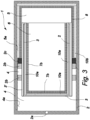
- fig. 3 In fig. 3 is shown a plunger pressure accumulator structurally similar to that of fig. 1 , but the length to transverse width ratio of its plunger 3 is less, being about 1,4. It can be seen from fig. 3 that, when the shell 2 is dimensioned in keeping with the width of a plunger, the second subspace 5, and the optional third subspace 6 shown in fig. 3 , increase in volume considerably with respect to the internal surface 5a (which is the heat transfer area) of the subspace 5.
- the shell 2 has even more favorable facilities in its interior space of providing the plunger pressure accumulator 1 with a necessary number of regenerators 7a, 7b, 8.
- the mass of regenerators will be sufficient for achieving a desired recovery of heat.
- the third subspace 6 internal of the hollow plunger 3 can be set up with several layers of regenerators 7b. It is preferred that, in terms of its length parallel to the direction of motion, the plunger 3 be 0,01 to 1000-fold in proportion to its transverse width. Consequently, the plunger 3 of the invention, equipped with the regenerator 7b, can have a width which even exceeds its length parallel to the direction of motion.
- such a plunger or floating piston solution provides a cost effective way of constructing truly heavy-duty and structurally durable plunger pressure accumulators because, with the exception of an outer surface of the plunger 3, its structure does not require perfectly finished surfaces, nor are there moving parts between the shell 2 and the plunger 3.
- fig. 2 shows background embodiment relating to the invention, wherein the slide element, which is denoted with reference numeral 2b', is structurally different from the annular slide bearing elements 2b presented in figs. 1 and 3 .
- Fig. 2 shows primarily the features essential for understanding this particular embodiment.
- the slide element 2b' is preferably a thin-walled tube.
- the thin-walled tube 2b' extends preferably co-directionally with the motion of a plunger 30 substantially across or all the way across the interior space of the shell 2.
- the internal surface of the tube 2b' constitutes a sliding surface upon which the plunger 30 is resting while moving in the interior space of the shell 2.
- the plunger 30 is depicted here as a piston included in a traditional piston accumulator, but it can also be structurally similar to the plunger 3 shown in fig. 1 .
- the slide element 2b' is made of material as small as possible in terms of its specific heat capacity and wall thickness. Depending on the material, it is in any case preferred for the wall thickness not to exceed 0,5 millimeters. A lower limit for the wall thickness is only defined by the characteristics of existing materials as well as those to be developed in the future.
- the sleeve 2b' is preferably dimensioned in such a way that its outer surface remains a distance apart from the internal surface 4a of the first subspace 4 and from the internal surface 5a of the second subspace 5.
- the sleeve 2b' is dimensioned in the second subspace 5 so as to leave a gap 2b" between en end face of the shell 2 and an edge of the sleeve. Therefore, in the second subspace 5, and between the sleeve 2b' and the internal surfaces 5a and 5a of the second subspace 5 and the first subspace 4, exists an equal pressure. It is possible to provide the slide element 2b' with separate support elements (not shown) for supporting it on the internal surfaces 5a and 4a.
- the sleeve 2b' can have its outer surface dimensioned in such a way that the sleeve's outer surface is in contact with the internal surfaces 4a and 5a.
- the distance from sliding surfaces of the piston 30 to the internal surfaces 4a and 5a is at least equal to the wall thickness of the slide element 2b'.
- regenerator 8 which can be fitted between the outer surface of the sleeve 2b' and the internal surface 5a (and optionally the internal surface 4a of the first subspace 4).
- the regenerator 8 participates in supporting the slide element 2b' in place in a direction transverse to the motion direction of the piston 30.
- a regenerator 7b which is thus only presented by way of example, can be arranged to be stationary relative to the piston 30.
- regenerators 7a and 7b as well as insulating layers 10a and 10b, and which need not be described in this context.
- the plunger pressure accumulator 1 can be provided with other equipment for improving a plunger pressure accumulator of the invention in terms of its functionality, as well as for improving the overall efficiency of a hydraulic external system or other external system communicating with the plunger pressure accumulator.
- fig. 4 shows a heat exchanger denoted with reference numeral 11.
- the heat exchanger 11 is disposed in the second subspace 5 within a zone between an outer surface of the plunger 3 and an internal surface of the second subspace 5, for example inside a mesh-like regenerator 8 (a heat transfer device).
- a plunger pressure accumulator of the invention wherein the motion of the plunger 3 allows the positioning of regenerators and other stationary additional features.
- the heat exchanger 11 has a function of bringing thermal energy from an external system into the second subspace 5 so as to replace, whenever necessary, the thermal energy displaced from gas and regenerators or heat transfer devices into the environment (this occurring to a certain extent especially in long compression phases and in the static compression phase of a plunger pressure accumulator).
- the thermal energy is brought to the heat exchanger for example from the cooling fluid or exhaust gases of internal combustion engines, from power plants based on renewable energy, such as solar energy, and/or from industrial processes in general.
- Operation of the heat exchanger 11 can be made automatic (active) for example by means of control elements 22a between the heat exchanger 11 and an external system 22, which are used for controlling the supply of thermal energy contained for example in a fluid substance (gas, liquid) to the heat exchanger 11 and thereby into the second subspace 5.
- the supply of thermal energy can be controlled, for example with the control elements 22a, on the basis of parameters obtained for example from the second subspace 5, such as gas temperature, pressure and/or a working phase of the plunger pressure accumulator 1.
- the heat exchanger 11 enables a removal of heat from the second subspace 5.
- Fig. 4 shows also cooling means 12a and 12b.
- the cooling means 12a consist of cooling ribs or the like disposed on an outer surface of the shell 2 at the first subspace 4.
- the purpose of these is to prevent the temperature of a hydraulic fluid present in the first subspace 5 from increasing too much. In other words, the purpose thereof is to cool the hydraulic fluid as may be needed.
- the thermal energy that has transferred from hydraulic fluid to the cooling means 12a and/or 12b can be recovered and exploited for example in the heat exchanger 11.
Landscapes
- Engineering & Computer Science (AREA)
- Physics & Mathematics (AREA)
- Fluid Mechanics (AREA)
- Mechanical Engineering (AREA)
- General Engineering & Computer Science (AREA)
- Chemical & Material Sciences (AREA)
- Analytical Chemistry (AREA)
- Supply Devices, Intensifiers, Converters, And Telemotors (AREA)
Description
- The invention relates to a plunger pressure accumulator, comprising: a shell with an interior space defined by its walls; a plunger which is adapted to move in a longitudinal direction of the shell into the interior space of the shell; said space being divided into at least two subspaces, the first subspace of which is suppliable with the hydraulic fluid of an external system and the second subspace is provided with a pressurized gas.
- Pressure accumulators are typically used as a part of the energy recovery system in some hydraulic system to improve the hydraulic system's overall efficiency. Hydraulic energy is stored in a pressure accumulator by using a hydraulic fluid of the hydraulic system to compress the pressure accumulator's gas present in one subspace. In a compression phase, the gas temperature rises. Available today are prior known pressure accumulators of various designs of which can be mentioned diaphragm accumulators, bladder accumulators and piston accumulators. These are all identical in terms of basic design and operation, i.e. the shell houses two subspaces, the first subspace of which is supplied with a hydraulic fluid for compressing a gas present in the second subspace. Operation of the diaphragm and bladder accumulator is based on the deformation of a diaphragm or bladder between the spaces, allowing in the compression phase a reduction of the second subspace volume (compression of the gas). These are employed typically for the equalization of pressure fluctuations in hydraulic systems.
- The piston accumulator, on the other hand, includes a piston, which is capable of sliding in contact with an internal surface of the shell in response to a force generated by a hydraulic fluid, and which also divides an interior space of the shell into two aforesaid subspaces. Typical accumulators are known from
WO 2010/134840 A1 . - In currently available pressure accumulators, the heat generated in a compression phase strives and begins to flow from pressure accumulator to environment. This constitutes a factor impairing the efficiency of a pressure accumulator. Especially in bladder and diaphragm accumulators, the elimination of this drawback is difficult because of deformations of the diaphragm or bladder. It is prior known to employ a foam type material in the gas space of bladder accumulators as presented on the internet site: http://www.hydac.com.au/www.hydac.com.au/news technews blad-derwithfoam.aspx. In this solution, after the heat has transferred both into the gas and into the foam type material, the heat generated in the compression phase begins to migrate freely to its surroundings, i.e. into a hydraulic fluid enclosing the bladder. As for piston pressure accumulators, the publication
US 8201582 B2 discloses interconnected leaf elements, which are provided between the end of one of the subspaces and the piston and which open in the direction of a piston movement and which function as a compressible regenerator. In one embodiment (fig. 3 ) of the publication there is presented an insulating layer provided on the internal surface of one subspace and having each leaf element fastened thereto. The piston is also provided with bellows, which operate as a vibration damper and which, due to the design and location thereof (in a direct contact with hydraulic fluid), adversely transfer heat from the gas directly to the hydraulic fluid of the first subspace and further into the environment. Such a structure, in which a complicated compressible regenerator is in contact with and in motion relative to many elements, such the shell, the piston, and the deforming insulator, is susceptible to damage. In addition, this imposes high quality requirements on the entire internal surface of a shell and on the external surface of a piston, which in turn increases manufacturing costs. - It is an objective of the present invention to provide a plunger pressure accumulator, in which the aforesaid drawbacks can be eliminated or at least substantially alleviated. An objective of the invention is to provide a plunger pressure accumulator, wherein, with a structure more cost efficient than before, it is possible to maintain the heat generated in one of the subspaces and to release it at a correct moment, for example in a discharge phase.
- The aforesaid objective of the invention is attained according to the invention in such a way that in the interior space of the shell between the plunger and the shell is arranged a slide bearing element upon which the plunger is supported to move to a distance apart from an internal surface of the first subspace and from an internal surface of the second subspace, that the plunger pressure accumulator is provided with at least one regenerator which is stationary relative to the shell or the plunger as the plunger moves, and in that between the plunger (3) and the shell (2) is provided a sealing element (2c) producing a sealing effect, which, together with the plunger (3), divides the space in a longitudinal direction of the shell (2) into the first subspace (4) and the second subspace (5).
- What is achieved with this type of plunger pressure accumulator is that a construction simpler than before enables one of the subspaces (the shell) as well as the plunger to be provided with a regenerator, for example between the movable plunger and an internal surface of the shell, as the plunger is discrete (not in contact with) from the shell. What is avoided with the plunger pressure accumulator construction according to the invention is an expensive operation of machining the internal shell surfaces into a sliding surface for the plunger, whereby finishing work is not required.
- Preferred embodiments of the invention are presented in the dependent claims. These disclose additional features capable of improving the functionality and efficiency of a plunger pressure accumulator of the invention.
- The invention will now be described more precisely with reference to the accompanying drawings, in which:
- Fig. 1
- shows a cross-section for a plunger pressure accumulator according to one preferred embodiment of the invention, which is provided with a ram, and
- Fig. 2
- shows a cross-section for a plunger pressure accumulator according to a second preferred embodiment of the invention,
- Fig. 3
- shows a cross-section for a plunger pressure accumulator according to a third preferred embodiment of the invention, which is provided with an expanded shell and plunger, and
- Fig. 4
- shows a cross-section for a plunger pressure accumulator according to a fourth preferred embodiment of the invention, which is provided with a heat exchanger and cooling means.
- Hence, in
fig. 1 there is shown a plunger pressure accumulator according to one preferred embodiment of the invention, which is denoted with reference numeral 1. In this embodiment, the plunger pressure accumulator 1 comprises anelongated shell 2 with an interior space defined by its walls. The space is provided with a plunger having its body denoted withreference numeral 3. In this embodiment, theplunger 3 is an elongated hollow sleeve type element with a closed first end. Thus, in this case, the plunger is annular in its cross-section, but the shape is not necessarily limited to that. The cross-section can also be for example a square or rectangle. Likewise, theshell 2 can have a correspondingly deviant cross-sectional shape. - Between the
plunger 3 and theshell 2 is provided aslide element 2b of the invention, upon which theplunger 3 is supported to move in a space. Therefore, the structure of a plunger pressure accumulator 1 shown infig. 1 indeed comprises a plunger as far as its piston is concerned. The slide element may consist of one or more annularslide bearing elements 2b disposed successively in a longitudinal direction of the shell. In this case, theslide element 2b is made stationary relative to theshell 2, but it can also be made stationary relative to theplunger 3.Fig. 1 presents two slide bearing elements. - Between the
plunger 3 and theshell 2 is further provided a sealingelement 2c or some other element, which establishes a sealing effect and, together with theplunger 3, divides the space in a lengthwise direction of theshell 2 into twosubspaces element 2c is made stationary relative to theshell 2, thereby leaving the sealing surface in engagement with an external surface 3' of theplunger 3. - Of these, the
first subspace 4 is suppliable with a hydraulic fluid by way of aport 2a provided in connection with theshell 2. The source of hydraulic fluid is typically some external system, including a hydraulic circuit that theplunger pressure accumulator 3 is in communication with. Thesecond subspace 5 is provided with a pressurized gas. Further in this embodiment, the space inside the walls of thehollow plunger 3 establishes athird subspace 6 which is in communication with thesecond subspace 5. Hence, thethird subspace 6 also contains pressurized gas at a pressure equal to that of thesecond subspace 5. The pressurized gas consists of a compressible gas. This compression takes place as thefirst subspace 4 is supplied with an incompressible or substantially incompressible hydraulic fluid from an external system. As a result of this, theplunger 3 or some other corresponding element moves (to the right infig. 1 ), thereby reducing a combined volume of thesecond subspace 5 and thethird subspace 6. Another result of this is the warming of pressurized gas in the second andthird subspaces - In a preferred embodiment of the invention, the
plunger 3 comprises a first insulating layer, which is denoted withreference numeral 10a. The firstinsulating layer 10a is preferably disposed in engagement with an inner surface of the walls of theplunger 3 so as to cover the entire internal surface of theplunger 3. - The
plunger pressure accumulator 3 according to the invention is provided with at least one regenerator, which is stationary relative to theshell 2 or theplunger 3.Fig. 1 shows tworegenerators plunger pressure accumulator 3 of the invention. It should be noted that these are merely examples of regenerator configurations, nor is the invention limited to these configurations and positions. Thus, theregenerator 7a presents one solution for a type of regenerator which is stationary relative to theshell 2. Theelongated regenerator 7a is attached to an end face of theshell 2 and adapted to extend a distance into thethird subspace 6. Hence, the first insulatinglayer 10a provided on theplunger 3 surrounds theregenerator 7a at least partially. As theplunger 3 is moving to the right infig. 1 , the regenerator will be respectively surrounded by the first insulatinglayer 10a over a longer distance. Theregenerator 7a and/or theplunger 3 can also be designed in terms of its length so as to be surrounded by the insulatinglayer 10a only in a compression phase, i.e. as thepiston 3 is being displaced by hydraulic pressure (to the right infig. 1 ). The structure and/or material of theregenerator 7a is such that the pressurized gas present in thethird subspace 6 is able to flow into theregenerator 7a and, if necessary, through theregenerator 7a into thesecond subspace 5. - As an alternative or in addition to the
regenerator 7a, the plunger pressure accumulator 1 may include aregenerator 7b which is stationary relative to theplunger 3.Fig. 1 shows aregenerator 7b, which has a cavity type structure and which is disposed in engagement with the insulatinglayer 10a so as to have the first insulatinglayer 10a completely covered by theregenerator 7b. Thus, when the plunger pressure accumulator 1 is in a compressed condition, theregenerator 7a (if present), which is stationary relative theshell 2, has moved into a cavity of theregenerator 7b which is stationary relative to theplunger 3. In this embodiment, it is the cavity of theregenerator 7b which establishes thethird subspace 6. Theinsulator layer 10a of theplunger 3 can be alternatively omitted and optionally replaced for example with a thicker layer of regenerator material, whereby theregenerator 7b will have a greater mass and heat capacity. - In a preferred embodiment of the invention, the internal surface of the
shell 2 defined by thesecond subspace 5 is provided with a second insulatinglayer 10b. This can be implemented in such a way that the second insulatinglayer 10b is attached to theshell 2 in a manner making it stationary relative to theshell 2. This is made possible in a particularly advantageous way by having theplunger 3 supported to move with the assistance of theslide elements 2b to a distance apart from aninternal surface 4a of thefirst subspace 4 and from aninternal surface 5a of thesecond subspace 5. Accordingly, as opposed to prior known solutions, for the second insulating layer there is left, between theplunger 3 and theinternal surface 4a, a space (which therefore in this case is a part of the second subspace 5) in which the second insulatinglayer 10b can be easily accommodated inside theshell 2 - What can be further seen in
fig. 1 is one further embodiment for a second regenerator, which is stationary relative to theshell 2. The second regenerator is denoted withreference numeral 8, and it is in this case constructed as a layer of desired thickness around the insulatinglayer 10b. It should be noted that, from the operational standpoint of the plunger pressure accumulator 1 of the invention, the second insulatinglayer 10b is not an absolute necessity, which is why thesecond regenerator 8 can be optionally disposed in a direct engagement with theinternal surface 5a of thesecond subspace 5 of theshell 2. This is made possible by having theplunger 3 supported to move, according to the invention, with the assistance of theslide elements 2b to a distance apart from theinternal surface 4a of thefirst subspace 4 and from theinternal surface 5a of thesecond subspace 5. - The plunger type structure of a plunger pressure accumulator according to the invention enables the use of diverse materials in regenerators. The employed material can be for example a metal, ceramic, composite and/or polymer. It is also possible to use a material, such as paraffin, based on phase transition. In addition, the structure of regenerators can be preferably sintered, mesh-like, fibrous, granular and/or foamy. The implementation of structurally other types of regenerators is possible. The purpose of such structures is to provide an interior space of the
shell 2, especially thesecond subspace 5, at desired locations, with a regenerator sufficient in terms of its thermal capacity, but also in terms of its heat transfer capacity. Particularly the regenerator, which is in communication with a gas of thesecond subspace 5, as well as with a gas of thethird subspace 6, must have an area which is large in comparison with that of the second subspace'sinternal surface 5a. An objective is to collect from the gas as thoroughly as possible the heat generated during the compression phase and to deliver it back into the gas during a discharge phase or expansion phase. At the same time, there is provided an effective blockage of heat flows towards the shell by binding the heat as well as by using its appropriate structure and materials for impeding and stopping the flow of heat into the shell structure. This objective is attained particularly well with a plunger pressure accumulator construction of the invention, since theplunger 3 does not hinder the positioning of regenerators particularly in thesecond subspace 5. Depending on the material and structure of a regenerator or regenerators, there will be achieved for the regenerator a surface area which is approximately 10 to 1000-fold compared to theinternal surface 5a while the thermal capacity of the regenerator or regenerators is nevertheless sufficient for the recovery of heat generated in the gas. However, the regenerator's surface area with respect to theinternal surface 5a can be other than this. - Further in a plunger pressure accumulator 1 of the invention, the
regenerator regenerator 7a; 7b; 8 also works as an element which delivers the heat stored therein as desired. Thus, the regenerator or heat transfer device allows the thermal energy, stored in theregenerator 7a; 7b; 8 in the compression phase of pressurized gas, to be released at the latest when the plunger pressure accumulator 1 terminates its discharge phase. In a typical case, the duration of a discharge phase is 1-60 seconds but, depending on the application and the plunger pressure accumulator's capacity, it may deviate from the aforesaid time frame, being for example 0,5-600 seconds. Naturally, the regenerator or heat transfer device can be constructed so as to deliver thermal energy even after the discharge phase has terminated. - In
fig. 1 is shown an elongated plunger, whose length parallel to the direction of motion is about 2,7-fold with respect to its width transverse to the lengthwise dimension, in this case with respect to the outer diameter of a plunger with circular cross-section. Infig. 3 is shown a plunger pressure accumulator structurally similar to that offig. 1 , but the length to transverse width ratio of itsplunger 3 is less, being about 1,4. It can be seen fromfig. 3 that, when theshell 2 is dimensioned in keeping with the width of a plunger, thesecond subspace 5, and the optionalthird subspace 6 shown infig. 3 , increase in volume considerably with respect to theinternal surface 5a (which is the heat transfer area) of thesubspace 5. As a result, theshell 2 has even more favorable facilities in its interior space of providing the plunger pressure accumulator 1 with a necessary number ofregenerators third subspace 6 internal of thehollow plunger 3 can be set up with several layers ofregenerators 7b. It is preferred that, in terms of its length parallel to the direction of motion, theplunger 3 be 0,01 to 1000-fold in proportion to its transverse width. Consequently, theplunger 3 of the invention, equipped with theregenerator 7b, can have a width which even exceeds its length parallel to the direction of motion. Generally speaking, such a plunger or floating piston solution provides a cost effective way of constructing truly heavy-duty and structurally durable plunger pressure accumulators because, with the exception of an outer surface of theplunger 3, its structure does not require perfectly finished surfaces, nor are there moving parts between theshell 2 and theplunger 3. - In
fig. 2 is shown background embodiment relating to the invention, wherein the slide element, which is denoted with reference numeral 2b', is structurally different from the annularslide bearing elements 2b presented infigs. 1 and3 .Fig. 2 shows primarily the features essential for understanding this particular embodiment. It can be seen fromfig. 2 that theslide element 2b' is preferably a thin-walled tube. The thin-walled tube 2b' extends preferably co-directionally with the motion of aplunger 30 substantially across or all the way across the interior space of theshell 2. In this case, the internal surface of thetube 2b' constitutes a sliding surface upon which theplunger 30 is resting while moving in the interior space of theshell 2. Theplunger 30 is depicted here as a piston included in a traditional piston accumulator, but it can also be structurally similar to theplunger 3 shown infig. 1 . To ensure operation as favorable as possible, theslide element 2b' is made of material as small as possible in terms of its specific heat capacity and wall thickness. Depending on the material, it is in any case preferred for the wall thickness not to exceed 0,5 millimeters. A lower limit for the wall thickness is only defined by the characteristics of existing materials as well as those to be developed in the future. Thesleeve 2b' is preferably dimensioned in such a way that its outer surface remains a distance apart from theinternal surface 4a of thefirst subspace 4 and from theinternal surface 5a of thesecond subspace 5. This enables aregenerator 8 to be disposed between the outer surface of thesleeve 2b' and at least theinternal surface 4a and optionally theinternal surface 5a. Thesleeve 2b' is dimensioned in thesecond subspace 5 so as to leave agap 2b" between en end face of theshell 2 and an edge of the sleeve. Therefore, in thesecond subspace 5, and between thesleeve 2b' and theinternal surfaces second subspace 5 and thefirst subspace 4, exists an equal pressure. It is possible to provide theslide element 2b' with separate support elements (not shown) for supporting it on theinternal surfaces sleeve 2b' can have its outer surface dimensioned in such a way that the sleeve's outer surface is in contact with theinternal surfaces piston 30 to theinternal surfaces slide element 2b'. - In the embodiment shown in
fig. 2 , it is possible that at least thesecond subspace 5, and optionally thefirst subspace 4, be provided with aregenerator 8 which can be fitted between the outer surface of thesleeve 2b' and theinternal surface 5a (and optionally theinternal surface 4a of the first subspace 4). Hence, theregenerator 8 participates in supporting theslide element 2b' in place in a direction transverse to the motion direction of thepiston 30. Further in this case, aregenerator 7b, which is thus only presented by way of example, can be arranged to be stationary relative to thepiston 30. In addition to this, to the arrangement offig. 2 can be applied solutions, which are shown infigs. 1 and3 and involveregenerators layers - Moreover, the plunger pressure accumulator 1 according to the invention can be provided with other equipment for improving a plunger pressure accumulator of the invention in terms of its functionality, as well as for improving the overall efficiency of a hydraulic external system or other external system communicating with the plunger pressure accumulator. As an example,
fig. 4 shows a heat exchanger denoted withreference numeral 11. Theheat exchanger 11 is disposed in thesecond subspace 5 within a zone between an outer surface of theplunger 3 and an internal surface of thesecond subspace 5, for example inside a mesh-like regenerator 8 (a heat transfer device). This is made possible by a plunger pressure accumulator of the invention, wherein the motion of theplunger 3 allows the positioning of regenerators and other stationary additional features. Theheat exchanger 11 has a function of bringing thermal energy from an external system into thesecond subspace 5 so as to replace, whenever necessary, the thermal energy displaced from gas and regenerators or heat transfer devices into the environment (this occurring to a certain extent especially in long compression phases and in the static compression phase of a plunger pressure accumulator). The thermal energy is brought to the heat exchanger for example from the cooling fluid or exhaust gases of internal combustion engines, from power plants based on renewable energy, such as solar energy, and/or from industrial processes in general. Operation of theheat exchanger 11 can be made automatic (active) for example by means ofcontrol elements 22a between theheat exchanger 11 and anexternal system 22, which are used for controlling the supply of thermal energy contained for example in a fluid substance (gas, liquid) to theheat exchanger 11 and thereby into thesecond subspace 5. The supply of thermal energy can be controlled, for example with thecontrol elements 22a, on the basis of parameters obtained for example from thesecond subspace 5, such as gas temperature, pressure and/or a working phase of the plunger pressure accumulator 1. Whenever necessary, theheat exchanger 11 enables a removal of heat from thesecond subspace 5. -
Fig. 4 shows also cooling means 12a and 12b. The cooling means 12a consist of cooling ribs or the like disposed on an outer surface of theshell 2 at thefirst subspace 4. Alternatively, or in addition to theribs 12a, in engagement with thefirst subspace 4, for example on itsinternal surface 4a, can be disposedconduits 12b for liquid cooling. The purpose of these is to prevent the temperature of a hydraulic fluid present in thefirst subspace 5 from increasing too much. In other words, the purpose thereof is to cool the hydraulic fluid as may be needed. The thermal energy that has transferred from hydraulic fluid to the cooling means 12a and/or 12b can be recovered and exploited for example in theheat exchanger 11. On the other hand, it is also possible to provide means from theheat exchanger 11 to the cooling means 12a and/or 12b, which can be used, as necessary, for cooling the hydraulic fluid present in thesubspace 5. These actions can be controlled for example by means of thecontrol elements 22a the same way as in relation to theheat exchanger 11. It is also conceivable that, in extreme conditions, such as at sub-zero temperatures, it is possible to introduce, particularly by way of the cooling means 12b, a medium capable of warming up the hydraulic fluid. - The present invention is not limited merely to the foregoing embodiments but can be applied within the scope of protection defined by the appended claims.
Claims (21)
- A plunger pressure accumulator (1), comprising: a shell (2) with an interior space defined by its walls; a plunger (3; 30) which is adapted to move relative to the shell (2) into the interior space of the shell (2); said space being divided into at least two subspaces (4 and 5), the first subspace (4) of which is suppliable with the hydraulic fluid of an external system and the second subspace (5) is provided with a pressurized gas, wherein in the interior space of the shell (2) between the plunger (3; 30) and the shell (2) is arranged a slide bearing element (2b) upon which the plunger (3) is supported to move to a distance apart from an internal surface (4a) of the first subspace (4) and from an internal surface (5a) of the second subspace (5), wherein between the plunger (3) and the shell (2) is provided a sealing element (2c) producing a sealing effect, which, together with the plunger (3), divides the space in a longitudinal direction of the shell (2) into the first subspace (4) and the second subspace (5), characterized in that the plunger pressure accumulator (1) is provided with at least one regenerator (7a; 7b; 8) which is stationary relative to the shell (2) or the plunger (3) as the plunger (3) moves.
- A plunger pressure accumulator (1) according to claim 1, characterized in that an outer surface (3') of the plunger (3) is surrounded across said first end area by the first subspace (4) and across said second end area by the second subspace (5).
- A plunger pressure accumulator (1) according to claim 1 or 2, characterized in that the slide bearing element (2b) comprises one or more annular slide bearing elements, which is or are adapted to be stationary relative to the shell (2).
- A plunger pressure accumulator (1) according to any of the preceding claims 1-3, characterized in that the slide bearing element (2b) comprises one or more annular slide bearing elements, which is or are adapted to be stationary relative to the plunger (3).
- A plunger pressure accumulator according to any of the preceding claims 1-4, characterized in that the plunger (3) comprises: a third subspace (6) which is in communication with the second subspace (5).
- A plunger pressure accumulator according to any of the preceding claims 1-5, characterized in that the plunger comprises an insulating layer (10a), which surrounds partially or completely said at least one regenerator (7a; 7b) at least in the compression phase of pressurized gas.
- A plunger pressure accumulator according to any of the preceding claims 1-6, characterized in that at least the shell (2) has the internal surface (5a) of its second subspace (5) surrounded by a second regenerator (8).
- A plunger pressure accumulator (1) according to any of the preceding claims 1-7, characterized in that the second subspace (5) has its internal surface provided with a second insulating layer (10b).
- A plunger pressure accumulator (1) according to any of the preceding claims 1-8, characterized in that the shell (2) has its outer surface provided with a third insulating layer.
- A plunger pressure accumulator (1) according to any of the preceding claims 1-9, characterized in that in connection with the shell (2) is provided a heat exchanger (11), which comprises means for supplying the pressurized gas with extra heat produced by an external system.
- A plunger pressure accumulator (1) according to any of the preceding claim 10, characterized in that the heat exchanger (11) is located inside a space defined by the second insulator layer (10b) and/or the third insulating layer.
- A plunger pressure accumulator (1) according to any of the preceding claims 1-11, characterized in that in connection with the second subspace (5) are provided cooling means (12a; 12b) for cooling a hydraulic fluid present in the plunger pressure accumulator (1).
- A plunger pressure accumulator (1) according to any of the preceding claims 7-12, characterized in that the at least one regenerator (7b) arranged in the plunger pressure accumulator (1) is stationary relative to the plunger (3) and which is completely surrounded by the first insulating layer (10a).
- A plunger pressure accumulator (1) according to any of the preceding claims 1-13, characterized in that the plunger (3) is an elongated hollow element, which is closed at its first end face and whose hollow second end face opens into the second subspace (5).
- A plunger pressure accumulator (1) according to any of the preceding claims 1-14, characterized in that, in terms of its length parallel to motion, the plunger (3) is 0,01 to 1000-fold as compared to its transverse width.
- A plunger pressure accumulator (1) according to any of the preceding claims 1-15, characterized in that the regenerator (7b), which is stationary relative to the plunger, extends in a longitudinal direction of the shell (2) a distance into the second subspace (5).
- A plunger pressure accumulator (1) according to any of the preceding claims 1-16, characterized in that said at least one regenerator (7a; 7b) is structurally constructed as a heat transfer device, whereby the regenerator (7a; 7b) has a structure which allows the thermal energy stored in the regenerator (7a; 7b) in the compression phase of pressurized gas to be released at the latest when a discharge phase of the plunger pressure accumulator (1) terminates.
- A plunger pressure accumulator (1) according to claim 17, characterized in that the discharge phase has a duration of 1-60 seconds.
- A plunger pressure accumulator (1) according to any of the preceding claims 1-18, characterized in that the structure and/or material of the second regenerator (8) is selected to enable the regenerator (8) to operate as a stabilizing element for reducing the flow of gas in the second subspace (5).
- A plunger pressure accumulator (1) according to any of the preceding claims 1-19, characterized in that the material of the regenerator (7a, 7b, 8) is a metal, ceramic and/or polymer.
- A plunger pressure accumulator (1) according to any of the preceding claims 1-20, characterized in that the regenerator (7a, 7b, 8) has a sintered, mesh-like, fibrous, granular and/or foamy structure.
Applications Claiming Priority (2)
| Application Number | Priority Date | Filing Date | Title |
|---|---|---|---|
| FI20146065A FI127612B (en) | 2014-12-04 | 2014-12-04 | Piston Accumulator |
| PCT/FI2015/050824 WO2016087711A1 (en) | 2014-12-04 | 2015-11-26 | Plunger pressure accumulator |
Publications (2)
| Publication Number | Publication Date |
|---|---|
| EP3227564A1 EP3227564A1 (en) | 2017-10-11 |
| EP3227564B1 true EP3227564B1 (en) | 2023-06-07 |
Family
ID=55072681
Family Applications (1)
| Application Number | Title | Priority Date | Filing Date |
|---|---|---|---|
| EP15820876.9A Active EP3227564B1 (en) | 2014-12-04 | 2015-11-26 | Plunger pressure accumulator |
Country Status (5)
| Country | Link |
|---|---|
| US (1) | US10480538B2 (en) |
| EP (1) | EP3227564B1 (en) |
| CN (1) | CN107208664B (en) |
| FI (1) | FI127612B (en) |
| WO (1) | WO2016087711A1 (en) |
Family Cites Families (24)
| Publication number | Priority date | Publication date | Assignee | Title |
|---|---|---|---|---|
| GB748469A (en) * | 1952-11-12 | 1956-05-02 | Applic Mach Motrices | An improved hydraulic shock absorber |
| US2817361A (en) | 1953-02-10 | 1957-12-24 | Mercier Jean | Piston accumulator |
| FR2236098B1 (en) * | 1973-07-04 | 1976-11-12 | Gratzmuller Jean Louis | |
| US4207563A (en) * | 1978-06-08 | 1980-06-10 | Midland-Ross Corporation | Gas charged accumulator with failure indicator |
| DE3333597A1 (en) | 1983-09-16 | 1985-04-18 | Wilkhahn Wilkening + Hahne GmbH + Co, 3252 Bad Münder | Accumulator |
| DE3334813A1 (en) * | 1983-09-26 | 1985-04-11 | Brown, Boveri & Cie Ag, 6800 Mannheim | HIGH PRESSURE STORAGE |
| US5664848A (en) * | 1996-05-21 | 1997-09-09 | Muraski; Richard E. | Apparatus for absorbing shocks in a vehicle braking system |
| US6322160B1 (en) * | 2000-04-12 | 2001-11-27 | Ford Global Technologies, Inc. | Method and apparatus for attenuating brake-induced vibrations |
| JP3513096B2 (en) * | 2000-09-25 | 2004-03-31 | トヨタ自動車株式会社 | Accumulator and abnormality detection device for accumulator |
| JP2002372008A (en) * | 2001-06-15 | 2002-12-26 | Oil Drive Kogyo Kk | Hydraulic jack incorporating accumulator and hydraulic elevator using the same |
| DE10253012A1 (en) * | 2002-04-26 | 2003-11-06 | Continental Teves Ag & Co Ohg | Pressure accumulator has third chamber of constant volume filled with liquid and bounded by metal bellows and piston, and hydraulic connection exists between second and third chambers and has valve unit controlled by piston movement |
| US7137491B2 (en) * | 2002-10-29 | 2006-11-21 | Arvinmeritor Technology, Llc | Shock absorber non-vibrating check valve assembly |
| DE10320373B4 (en) * | 2003-05-07 | 2009-01-15 | Lucas Automotive Gmbh | Gas pressure accumulator for a vehicle brake system |
| US7108016B2 (en) * | 2004-03-08 | 2006-09-19 | The United States Of America As Represented By The Administrator Of The Environmental Protection Agency | Lightweight low permeation piston-in-sleeve accumulator |
| US7104052B1 (en) * | 2005-03-15 | 2006-09-12 | Deere & Company | Hydraulic cylinder with integrated accumulator |
| US8020587B2 (en) | 2007-06-11 | 2011-09-20 | The United States Of America As Represented By The Administrator Of The U.S. Environmental Protection Agency | Piston-in sleeve hydraulic pressure accumulator |
| BRPI0816659A2 (en) * | 2007-09-10 | 2015-03-10 | Cameron Int Corp | PRESSURE-COMPENSED BULK BOTTLE |
| RU2382913C1 (en) * | 2008-09-01 | 2010-02-27 | Александр Анатольевич Строганов | Hydropneumatic accumulator with soft cellular filler |
| RU2383785C1 (en) | 2008-10-09 | 2010-03-10 | Александр Анатольевич Строганов | Hydro-pneumatic accumulator with compressed regenerator |
| US8225913B2 (en) * | 2009-04-16 | 2012-07-24 | S & T Daewoo Co. Ltd. | Damper for continuously variably adjusting damping force |
| RU2402697C1 (en) * | 2009-05-18 | 2010-10-27 | Александр Анатольевич Строганов | Device for hydraulic power recovery |
| RU2434159C1 (en) * | 2010-03-17 | 2011-11-20 | Александр Анатольевич Строганов | Conversion method of heat to hydraulic energy and device for its implementation |
| DE102011117533B4 (en) | 2011-11-03 | 2020-10-08 | Woodward L'orange Gmbh | Pressure accumulator and fuel injection device with such |
| DE102012112729B4 (en) * | 2012-12-20 | 2015-12-17 | Wp Performance Systems Gmbh | Damping valve arrangement for a semi-active vibration damper |
-
2014
- 2014-12-04 FI FI20146065A patent/FI127612B/en active IP Right Grant
-
2015
- 2015-11-26 US US15/532,536 patent/US10480538B2/en active Active
- 2015-11-26 CN CN201580073595.6A patent/CN107208664B/en not_active Expired - Fee Related
- 2015-11-26 WO PCT/FI2015/050824 patent/WO2016087711A1/en not_active Ceased
- 2015-11-26 EP EP15820876.9A patent/EP3227564B1/en active Active
Also Published As
| Publication number | Publication date |
|---|---|
| US20170268539A1 (en) | 2017-09-21 |
| FI127612B (en) | 2018-10-15 |
| WO2016087711A1 (en) | 2016-06-09 |
| CN107208664B (en) | 2019-12-24 |
| CN107208664A (en) | 2017-09-26 |
| FI20146065A7 (en) | 2016-06-05 |
| EP3227564A1 (en) | 2017-10-11 |
| US10480538B2 (en) | 2019-11-19 |
Similar Documents
| Publication | Publication Date | Title |
|---|---|---|
| CN112513428B (en) | Ultra-high temperature thermal energy storage system | |
| US20190393576A1 (en) | Thermal Management Systems for Battery Cells and Methods of Their Manufacture | |
| JPH11501387A (en) | Air-oil converter for energy storage | |
| US10047730B2 (en) | High-temperature thermal actuator utilizing phase change material | |
| JP7169923B2 (en) | Heat exchanger | |
| US20200318777A1 (en) | Decompression heat-insulating pipe structure | |
| US10480538B2 (en) | Plunger pressure accumulator | |
| KR101697523B1 (en) | Hydrogen storage alloy assembly and actuator using it | |
| US9512835B2 (en) | High pressure bellows assembly | |
| JP5746237B2 (en) | Piston and shock absorber with piston | |
| WO2006063004B1 (en) | Reduced shedding regenerator and method | |
| JP2005188601A (en) | Hydraulic shock absorber | |
| EP2019909A2 (en) | Methods and apparatus for actuator system | |
| US10550867B2 (en) | Ram air turbine structures for temperature dependent damping | |
| JP2016061364A (en) | Friction damper | |
| JP2018204763A (en) | Seismic isolation device | |
| JP2009197839A (en) | Flow path opening/closing device | |
| JPH11108098A (en) | Vibrational energy absorbing device | |
| JP2009250167A (en) | Constant delivery pump | |
| JP4172668B2 (en) | accumulator | |
| AU2003250031A1 (en) | Roll support device for continuous metallic strip casting | |
| JP3209404U (en) | Piston type accumulator | |
| US20210054808A1 (en) | Stirling engine | |
| JP2017072040A (en) | Plunger and manufacturing method of plunger | |
| CN102706138A (en) | Movable heat-insulation layer of muffle furnace |
Legal Events
| Date | Code | Title | Description |
|---|---|---|---|
| STAA | Information on the status of an ep patent application or granted ep patent |
Free format text: STATUS: THE INTERNATIONAL PUBLICATION HAS BEEN MADE |
|
| PUAI | Public reference made under article 153(3) epc to a published international application that has entered the european phase |
Free format text: ORIGINAL CODE: 0009012 |
|
| STAA | Information on the status of an ep patent application or granted ep patent |
Free format text: STATUS: REQUEST FOR EXAMINATION WAS MADE |
|
| 17P | Request for examination filed |
Effective date: 20170704 |
|
| AK | Designated contracting states |
Kind code of ref document: A1 Designated state(s): AL AT BE BG CH CY CZ DE DK EE ES FI FR GB GR HR HU IE IS IT LI LT LU LV MC MK MT NL NO PL PT RO RS SE SI SK SM TR |
|
| AX | Request for extension of the european patent |
Extension state: BA ME |
|
| DAV | Request for validation of the european patent (deleted) | ||
| DAX | Request for extension of the european patent (deleted) | ||
| STAA | Information on the status of an ep patent application or granted ep patent |
Free format text: STATUS: EXAMINATION IS IN PROGRESS |
|
| 17Q | First examination report despatched |
Effective date: 20191121 |
|
| INTG | Intention to grant announced |
Effective date: 20220729 |
|
| INTG | Intention to grant announced |
Effective date: 20220729 |
|
| GRAS | Grant fee paid |
Free format text: ORIGINAL CODE: EPIDOSNIGR3 |
|
| STAA | Information on the status of an ep patent application or granted ep patent |
Free format text: STATUS: GRANT OF PATENT IS INTENDED |
|
| GRAA | (expected) grant |
Free format text: ORIGINAL CODE: 0009210 |
|
| STAA | Information on the status of an ep patent application or granted ep patent |
Free format text: STATUS: THE PATENT HAS BEEN GRANTED |
|
| AK | Designated contracting states |
Kind code of ref document: B1 Designated state(s): AL AT BE BG CH CY CZ DE DK EE ES FI FR GB GR HR HU IE IS IT LI LT LU LV MC MK MT NL NO PL PT RO RS SE SI SK SM TR |
|
| REG | Reference to a national code |
Ref country code: GB Ref legal event code: FG4D |
|
| REG | Reference to a national code |
Ref country code: CH Ref legal event code: EP Ref country code: AT Ref legal event code: REF Ref document number: 1575865 Country of ref document: AT Kind code of ref document: T Effective date: 20230615 |
|
| REG | Reference to a national code |
Ref country code: DE Ref legal event code: R096 Ref document number: 602015083993 Country of ref document: DE |
|
| REG | Reference to a national code |
Ref country code: LT Ref legal event code: MG9D |
|
| REG | Reference to a national code |
Ref country code: NL Ref legal event code: MP Effective date: 20230607 |
|
| PG25 | Lapsed in a contracting state [announced via postgrant information from national office to epo] |
Ref country code: SE Free format text: LAPSE BECAUSE OF FAILURE TO SUBMIT A TRANSLATION OF THE DESCRIPTION OR TO PAY THE FEE WITHIN THE PRESCRIBED TIME-LIMIT Effective date: 20230607 Ref country code: NO Free format text: LAPSE BECAUSE OF FAILURE TO SUBMIT A TRANSLATION OF THE DESCRIPTION OR TO PAY THE FEE WITHIN THE PRESCRIBED TIME-LIMIT Effective date: 20230907 Ref country code: ES Free format text: LAPSE BECAUSE OF FAILURE TO SUBMIT A TRANSLATION OF THE DESCRIPTION OR TO PAY THE FEE WITHIN THE PRESCRIBED TIME-LIMIT Effective date: 20230607 |
|
| REG | Reference to a national code |
Ref country code: AT Ref legal event code: MK05 Ref document number: 1575865 Country of ref document: AT Kind code of ref document: T Effective date: 20230607 |
|
| PG25 | Lapsed in a contracting state [announced via postgrant information from national office to epo] |
Ref country code: RS Free format text: LAPSE BECAUSE OF FAILURE TO SUBMIT A TRANSLATION OF THE DESCRIPTION OR TO PAY THE FEE WITHIN THE PRESCRIBED TIME-LIMIT Effective date: 20230607 Ref country code: NL Free format text: LAPSE BECAUSE OF FAILURE TO SUBMIT A TRANSLATION OF THE DESCRIPTION OR TO PAY THE FEE WITHIN THE PRESCRIBED TIME-LIMIT Effective date: 20230607 Ref country code: LV Free format text: LAPSE BECAUSE OF FAILURE TO SUBMIT A TRANSLATION OF THE DESCRIPTION OR TO PAY THE FEE WITHIN THE PRESCRIBED TIME-LIMIT Effective date: 20230607 Ref country code: LT Free format text: LAPSE BECAUSE OF FAILURE TO SUBMIT A TRANSLATION OF THE DESCRIPTION OR TO PAY THE FEE WITHIN THE PRESCRIBED TIME-LIMIT Effective date: 20230607 Ref country code: HR Free format text: LAPSE BECAUSE OF FAILURE TO SUBMIT A TRANSLATION OF THE DESCRIPTION OR TO PAY THE FEE WITHIN THE PRESCRIBED TIME-LIMIT Effective date: 20230607 Ref country code: GR Free format text: LAPSE BECAUSE OF FAILURE TO SUBMIT A TRANSLATION OF THE DESCRIPTION OR TO PAY THE FEE WITHIN THE PRESCRIBED TIME-LIMIT Effective date: 20230908 |
|
| PG25 | Lapsed in a contracting state [announced via postgrant information from national office to epo] |
Ref country code: FI Free format text: LAPSE BECAUSE OF FAILURE TO SUBMIT A TRANSLATION OF THE DESCRIPTION OR TO PAY THE FEE WITHIN THE PRESCRIBED TIME-LIMIT Effective date: 20230607 |
|
| PG25 | Lapsed in a contracting state [announced via postgrant information from national office to epo] |
Ref country code: SK Free format text: LAPSE BECAUSE OF FAILURE TO SUBMIT A TRANSLATION OF THE DESCRIPTION OR TO PAY THE FEE WITHIN THE PRESCRIBED TIME-LIMIT Effective date: 20230607 |
|
| PG25 | Lapsed in a contracting state [announced via postgrant information from national office to epo] |
Ref country code: IS Free format text: LAPSE BECAUSE OF FAILURE TO SUBMIT A TRANSLATION OF THE DESCRIPTION OR TO PAY THE FEE WITHIN THE PRESCRIBED TIME-LIMIT Effective date: 20231007 |
|
| PG25 | Lapsed in a contracting state [announced via postgrant information from national office to epo] |
Ref country code: SM Free format text: LAPSE BECAUSE OF FAILURE TO SUBMIT A TRANSLATION OF THE DESCRIPTION OR TO PAY THE FEE WITHIN THE PRESCRIBED TIME-LIMIT Effective date: 20230607 Ref country code: SK Free format text: LAPSE BECAUSE OF FAILURE TO SUBMIT A TRANSLATION OF THE DESCRIPTION OR TO PAY THE FEE WITHIN THE PRESCRIBED TIME-LIMIT Effective date: 20230607 Ref country code: RO Free format text: LAPSE BECAUSE OF FAILURE TO SUBMIT A TRANSLATION OF THE DESCRIPTION OR TO PAY THE FEE WITHIN THE PRESCRIBED TIME-LIMIT Effective date: 20230607 Ref country code: PT Free format text: LAPSE BECAUSE OF FAILURE TO SUBMIT A TRANSLATION OF THE DESCRIPTION OR TO PAY THE FEE WITHIN THE PRESCRIBED TIME-LIMIT Effective date: 20231009 Ref country code: IS Free format text: LAPSE BECAUSE OF FAILURE TO SUBMIT A TRANSLATION OF THE DESCRIPTION OR TO PAY THE FEE WITHIN THE PRESCRIBED TIME-LIMIT Effective date: 20231007 Ref country code: EE Free format text: LAPSE BECAUSE OF FAILURE TO SUBMIT A TRANSLATION OF THE DESCRIPTION OR TO PAY THE FEE WITHIN THE PRESCRIBED TIME-LIMIT Effective date: 20230607 Ref country code: CZ Free format text: LAPSE BECAUSE OF FAILURE TO SUBMIT A TRANSLATION OF THE DESCRIPTION OR TO PAY THE FEE WITHIN THE PRESCRIBED TIME-LIMIT Effective date: 20230607 Ref country code: AT Free format text: LAPSE BECAUSE OF FAILURE TO SUBMIT A TRANSLATION OF THE DESCRIPTION OR TO PAY THE FEE WITHIN THE PRESCRIBED TIME-LIMIT Effective date: 20230607 |
|
| PG25 | Lapsed in a contracting state [announced via postgrant information from national office to epo] |
Ref country code: PL Free format text: LAPSE BECAUSE OF FAILURE TO SUBMIT A TRANSLATION OF THE DESCRIPTION OR TO PAY THE FEE WITHIN THE PRESCRIBED TIME-LIMIT Effective date: 20230607 |
|
| REG | Reference to a national code |
Ref country code: DE Ref legal event code: R097 Ref document number: 602015083993 Country of ref document: DE |
|
| PLBE | No opposition filed within time limit |
Free format text: ORIGINAL CODE: 0009261 |
|
| STAA | Information on the status of an ep patent application or granted ep patent |
Free format text: STATUS: NO OPPOSITION FILED WITHIN TIME LIMIT |
|
| PG25 | Lapsed in a contracting state [announced via postgrant information from national office to epo] |
Ref country code: DK Free format text: LAPSE BECAUSE OF FAILURE TO SUBMIT A TRANSLATION OF THE DESCRIPTION OR TO PAY THE FEE WITHIN THE PRESCRIBED TIME-LIMIT Effective date: 20230607 |
|
| PG25 | Lapsed in a contracting state [announced via postgrant information from national office to epo] |
Ref country code: SI Free format text: LAPSE BECAUSE OF FAILURE TO SUBMIT A TRANSLATION OF THE DESCRIPTION OR TO PAY THE FEE WITHIN THE PRESCRIBED TIME-LIMIT Effective date: 20230607 |
|
| 26N | No opposition filed |
Effective date: 20240308 |
|
| PG25 | Lapsed in a contracting state [announced via postgrant information from national office to epo] |
Ref country code: SI Free format text: LAPSE BECAUSE OF FAILURE TO SUBMIT A TRANSLATION OF THE DESCRIPTION OR TO PAY THE FEE WITHIN THE PRESCRIBED TIME-LIMIT Effective date: 20230607 Ref country code: IT Free format text: LAPSE BECAUSE OF FAILURE TO SUBMIT A TRANSLATION OF THE DESCRIPTION OR TO PAY THE FEE WITHIN THE PRESCRIBED TIME-LIMIT Effective date: 20230607 |
|
| REG | Reference to a national code |
Ref country code: DE Ref legal event code: R119 Ref document number: 602015083993 Country of ref document: DE |
|
| REG | Reference to a national code |
Ref country code: CH Ref legal event code: PL |
|
| PG25 | Lapsed in a contracting state [announced via postgrant information from national office to epo] |
Ref country code: MC Free format text: LAPSE BECAUSE OF FAILURE TO SUBMIT A TRANSLATION OF THE DESCRIPTION OR TO PAY THE FEE WITHIN THE PRESCRIBED TIME-LIMIT Effective date: 20230607 |
|
| PG25 | Lapsed in a contracting state [announced via postgrant information from national office to epo] |
Ref country code: LU Free format text: LAPSE BECAUSE OF NON-PAYMENT OF DUE FEES Effective date: 20231126 |
|
| PG25 | Lapsed in a contracting state [announced via postgrant information from national office to epo] |
Ref country code: CH Free format text: LAPSE BECAUSE OF NON-PAYMENT OF DUE FEES Effective date: 20231130 |
|
| GBPC | Gb: european patent ceased through non-payment of renewal fee |
Effective date: 20231126 |
|
| PG25 | Lapsed in a contracting state [announced via postgrant information from national office to epo] |
Ref country code: MC Free format text: LAPSE BECAUSE OF FAILURE TO SUBMIT A TRANSLATION OF THE DESCRIPTION OR TO PAY THE FEE WITHIN THE PRESCRIBED TIME-LIMIT Effective date: 20230607 Ref country code: LU Free format text: LAPSE BECAUSE OF NON-PAYMENT OF DUE FEES Effective date: 20231126 Ref country code: CH Free format text: LAPSE BECAUSE OF NON-PAYMENT OF DUE FEES Effective date: 20231130 |
|
| REG | Reference to a national code |
Ref country code: BE Ref legal event code: MM Effective date: 20231130 |
|
| REG | Reference to a national code |
Ref country code: IE Ref legal event code: MM4A |
|
| PG25 | Lapsed in a contracting state [announced via postgrant information from national office to epo] |
Ref country code: DE Free format text: LAPSE BECAUSE OF NON-PAYMENT OF DUE FEES Effective date: 20240601 Ref country code: IE Free format text: LAPSE BECAUSE OF NON-PAYMENT OF DUE FEES Effective date: 20231126 |
|
| PG25 | Lapsed in a contracting state [announced via postgrant information from national office to epo] |
Ref country code: GB Free format text: LAPSE BECAUSE OF NON-PAYMENT OF DUE FEES Effective date: 20231126 |
|
| PG25 | Lapsed in a contracting state [announced via postgrant information from national office to epo] |
Ref country code: BE Free format text: LAPSE BECAUSE OF NON-PAYMENT OF DUE FEES Effective date: 20231130 |
|
| PG25 | Lapsed in a contracting state [announced via postgrant information from national office to epo] |
Ref country code: FR Free format text: LAPSE BECAUSE OF NON-PAYMENT OF DUE FEES Effective date: 20231130 |
|
| PG25 | Lapsed in a contracting state [announced via postgrant information from national office to epo] |
Ref country code: IE Free format text: LAPSE BECAUSE OF NON-PAYMENT OF DUE FEES Effective date: 20231126 Ref country code: GB Free format text: LAPSE BECAUSE OF NON-PAYMENT OF DUE FEES Effective date: 20231126 Ref country code: FR Free format text: LAPSE BECAUSE OF NON-PAYMENT OF DUE FEES Effective date: 20231130 Ref country code: DE Free format text: LAPSE BECAUSE OF NON-PAYMENT OF DUE FEES Effective date: 20240601 Ref country code: BE Free format text: LAPSE BECAUSE OF NON-PAYMENT OF DUE FEES Effective date: 20231130 |
|
| PG25 | Lapsed in a contracting state [announced via postgrant information from national office to epo] |
Ref country code: BG Free format text: LAPSE BECAUSE OF FAILURE TO SUBMIT A TRANSLATION OF THE DESCRIPTION OR TO PAY THE FEE WITHIN THE PRESCRIBED TIME-LIMIT Effective date: 20230607 |
|
| PG25 | Lapsed in a contracting state [announced via postgrant information from national office to epo] |
Ref country code: BG Free format text: LAPSE BECAUSE OF FAILURE TO SUBMIT A TRANSLATION OF THE DESCRIPTION OR TO PAY THE FEE WITHIN THE PRESCRIBED TIME-LIMIT Effective date: 20230607 |
|
| PG25 | Lapsed in a contracting state [announced via postgrant information from national office to epo] |
Ref country code: CY Free format text: LAPSE BECAUSE OF FAILURE TO SUBMIT A TRANSLATION OF THE DESCRIPTION OR TO PAY THE FEE WITHIN THE PRESCRIBED TIME-LIMIT; INVALID AB INITIO Effective date: 20151126 |
|
| PG25 | Lapsed in a contracting state [announced via postgrant information from national office to epo] |
Ref country code: HU Free format text: LAPSE BECAUSE OF FAILURE TO SUBMIT A TRANSLATION OF THE DESCRIPTION OR TO PAY THE FEE WITHIN THE PRESCRIBED TIME-LIMIT; INVALID AB INITIO Effective date: 20151126 |
|
| PG25 | Lapsed in a contracting state [announced via postgrant information from national office to epo] |
Ref country code: TR Free format text: LAPSE BECAUSE OF FAILURE TO SUBMIT A TRANSLATION OF THE DESCRIPTION OR TO PAY THE FEE WITHIN THE PRESCRIBED TIME-LIMIT Effective date: 20230607 |