EP3227526B1 - Bohrlochabschlusssystem - Google Patents
Bohrlochabschlusssystem Download PDFInfo
- Publication number
- EP3227526B1 EP3227526B1 EP15802128.7A EP15802128A EP3227526B1 EP 3227526 B1 EP3227526 B1 EP 3227526B1 EP 15802128 A EP15802128 A EP 15802128A EP 3227526 B1 EP3227526 B1 EP 3227526B1
- Authority
- EP
- European Patent Office
- Prior art keywords
- sleeve
- completion system
- casing
- downhole completion
- communication
- Prior art date
- Legal status (The legal status is an assumption and is not a legal conclusion. Google has not performed a legal analysis and makes no representation as to the accuracy of the status listed.)
- Active
Links
Images





Classifications
-
- E—FIXED CONSTRUCTIONS
- E21—EARTH OR ROCK DRILLING; MINING
- E21B—EARTH OR ROCK DRILLING; OBTAINING OIL, GAS, WATER, SOLUBLE OR MELTABLE MATERIALS OR A SLURRY OF MINERALS FROM WELLS
- E21B34/00—Valve arrangements for boreholes or wells
- E21B34/06—Valve arrangements for boreholes or wells in wells
- E21B34/066—Valve arrangements for boreholes or wells in wells electrically actuated
-
- E—FIXED CONSTRUCTIONS
- E21—EARTH OR ROCK DRILLING; MINING
- E21B—EARTH OR ROCK DRILLING; OBTAINING OIL, GAS, WATER, SOLUBLE OR MELTABLE MATERIALS OR A SLURRY OF MINERALS FROM WELLS
- E21B2200/00—Special features related to earth drilling for obtaining oil, gas or water
- E21B2200/06—Sleeve valves
-
- E—FIXED CONSTRUCTIONS
- E21—EARTH OR ROCK DRILLING; MINING
- E21B—EARTH OR ROCK DRILLING; OBTAINING OIL, GAS, WATER, SOLUBLE OR MELTABLE MATERIALS OR A SLURRY OF MINERALS FROM WELLS
- E21B23/00—Apparatus for displacing, setting, locking, releasing or removing tools, packers or the like in boreholes or wells
- E21B23/06—Apparatus for displacing, setting, locking, releasing or removing tools, packers or the like in boreholes or wells for setting packers
-
- E—FIXED CONSTRUCTIONS
- E21—EARTH OR ROCK DRILLING; MINING
- E21B—EARTH OR ROCK DRILLING; OBTAINING OIL, GAS, WATER, SOLUBLE OR MELTABLE MATERIALS OR A SLURRY OF MINERALS FROM WELLS
- E21B33/00—Sealing or packing boreholes or wells
- E21B33/10—Sealing or packing boreholes or wells in the borehole
- E21B33/12—Packers; Plugs
- E21B33/128—Packers; Plugs with a member expanded radially by axial pressure
- E21B33/1285—Packers; Plugs with a member expanded radially by axial pressure by fluid pressure
Definitions
- the present invention relates to a downhole completion system arranged in a borehole.
- the downhole completion system comprises a production casing having an axial extension, an inside, an inner diameter and an opening for providing fluid communication between the borehole and the inside.
- a sleeve or a completion component is arranged at least partly movably along or rotatably around the axial extension, the sleeve or the completion component being arranged opposite the opening for opening, choking or closing the fluid communication, the sleeve having a profile facing the inside of the casing, and a sleeve control for moving the sleeve to open, choke or close the opening.
- WO2013079929 relates to an apparatus for controlling a downhole device in a well having a body with a control slot and pin movable in the slot.
- the slot has a first inactive loop in which the pin can cycle between different idling configurations, and a second active loop in which the pin can move between different configurations which correspond to active and inactive configurations of the downhole device.
- control lines extending from surface all the way down to the components several kilometres down the well on the outside of the production casing.
- the control lines thus have to extend past the main barriers, which induces a substantial risk of leaking barriers and thus the possibility of blowouts.
- a downhole completion system arranged in a borehole comprising:
- the downhole completion system arranged in a borehole may comprise:
- the sleeve control or component control communicates with surface with simple command signals to operate the valves without having to penetrate the primary barrier, i.e. the packer between the intermediate casing and the production casing, by means of control lines or the main casing itself.
- the primary barrier is meant the intermediate casing, the main barrier, i.e. the main packer, and the main production casing, i.e. the production casing, when the completion is not a double skin casing/completion.
- primary barrier is meant the intermediate casing, the main barrier, i.e. the main packer, and the main production casing, i.e. the outermost production casing.
- the downhole completion system as described above may further comprise a second communication module for communicating with the first communication module.
- second communication modules may be arranged in or nearby the casing collars functioning as nodes, or second communication modules may be submerged into the annulus above the main barrier packer.
- the second communication module may comprise a first communication unit and a second communication unit.
- first communication unit and the second communication unit may be electrically connected via electromagnetic induction.
- the first communication unit may be arranged on an outer face of the casing and the second communication unit is arranged on an inner face of the casing.
- the second communication module may comprise a third communication unit connected with the second communication unit by means of wiring or a conductor, such as a cable, a cord or a wire.
- a first part of the completion component may be the at least one member engaging the profile of a second part of the completion component.
- the second communication module may be arranged near a top of the borehole, submerged into an annulus between the production casing and a wall of the borehole or an intermediate casing, or connected to the production casing.
- first and second communication modules may communicate wirelessly by means of mud pulses, an electrical field, electromagnetic induction or acoustic waves.
- the power supply may be rechargeable.
- the power supply may be recharged by the first communication module converting the mud pulses, an electrical field or acoustic waves into electrical energy.
- the production casing may comprise annular barriers, each annular barrier comprising:
- fixation unit may have fixation elements extending radially towards the production casing.
- the production casing may comprise a restriction for fixating the fixation unit.
- the sleeve control may comprise a plurality of fixation units.
- the first communication module may comprise a propeller in connection with a generator for recharging the power supply by converting rotational energy generated by fluid in the production casing to electrical energy.
- the actuator may comprise an electrical motor powered by the power supply.
- the actuator may comprise a gear arrangement driven by the motor for moving the first part.
- the gear arrangement may be a worm drive providing an axial movement of the first part in relation to the second part.
- Said gear arrangement may comprise at least one gear wheel for rotating the first part in relation to the second part.
- the actuator may further comprise a cylinder having a cylinder chamber in which a first end of a cylinder shaft is arranged, a plunger connected to the shaft divides the chamber into a first chamber part and a second chamber part, a second end of the cylinder shaft is connected with the first part, the actuator further comprising a pump providing pressurised fluid into one of the chamber parts for moving the cylinder shaft and the first part along the axial extension.
- the downhole completion system as described above may comprise a plurality of openings in the production casing, a plurality of sleeves arranged opposite the openings and a plurality of sleeve controls, each sleeve control being arranged opposite a sleeve for opening, choking or closing the fluid communication through the opening.
- the first communication modules of the sleeve controls may communicate with each other.
- the sleeve controls may be connected to each other via a shaft or a wireline.
- the sleeve control may have a cross-sectional area which is at least 50% smaller than a cross-sectional area of the inside of the casing in a radial direction of the casing, preferably at least 45% smaller than the cross-sectional area of the inside of the casing, more preferably at least 35% smaller than the cross-sectional area of the inside of the casing.
- the production casing may comprise a lateral.
- the lateral may comprise a sleeve and a sleeve control.
- the lateral may comprise a completion component and a component control.
- first communication modules of the component controls may communicate with each other.
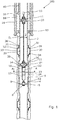
- Fig. 1 shows a downhole completion system 100 arranged in a borehole and comprising a production casing 2 having an axial extension, an inside 3 in which fluid flows for producing oil or gas.
- the production casing has an inner diameter D i and an opening for providing fluid communication between the borehole and the inside and allowing fluid from the formation and into the casing.
- the downhole completion system comprises a sleeve 5 movable along or rotatable around the axial extension.
- the sleeve is arranged opposite the opening for opening, choking or closing the fluid communication from the reservoir.
- the sleeve has a profile 6 facing the inside of the casing.
- the downhole completion system further comprises a sleeve control 7 for moving the sleeve to open, choke or close the fluid communication.
- the sleeve control 7 comprises a first part 8 having members 9 engaging the profile, and a second part 10 having a fixation unit 11 fixating the sleeve control in the casing.
- the sleeve control 7 comprises an actuator 12 for moving the first part 8 in relation to the second part 10, and a power supply 14, such as a battery, supplying power to the actuator.
- the sleeve control 7 further comprises a first communication module 15 for receiving control signals from surface to open, choke or close fluid communication.
- the sleeve control 7 is thus permanently installed in the production casing 2, ready to move the sleeve from one position to another in order to choke, open or close fluid communication from the reservoir.
- the sleeve control 7 has its own power supply and can operate on its own when receiving a control signal during production of fluid from the reservoir, without the well being intervened by commonly used intervention tools or having control lines penetrate the main barriers 65.
- the downhole completion system 100 further comprises a second communication module 16 for communicating with the first communication module 15.
- the second communication module 16 is submerged into an annulus 18 between the production casing 2 and a wall of an intermediate casing 19. In this way, the second communication module 16 can be lowered down the casing to a point above the packer 65 between the intermediate casing 19 and the production casing 2, so that the wiring 40 from the second communication module does not jeopardise the primary seal 65 of the well, and the second communication module 16 is also closer to the first communication module 15 than if the second communication module 16 was arranged at the top 17 of the well, as shown in Fig. 5 .
- the second communication module may also be connected to the production casing 2 before being lowered into the borehole as shown at the right side of Fig. 1 .
- the first and the second communication modules 15, 16 communicate wirelessly by means of mud pulses, an electrical field or acoustic waves, as illustrated by curved lines 91 in the drawings.
- the communication may be performed by means of induction between induction means in the first and the second communication modules.
- the first communication module is therefore capable of receiving control signals from surface and power for recharging the power supply.
- the first communication module is capable of sending signals or even data to the second communication module, e.g. data from a sensor arranged near the sleeve or the completion control.
- the second communication module 16 communicates through the wireline or through an umbilical to a control centre (not shown).
- a control signal is sent from the second communication module 16 to the first communication module 15 of the sleeve control which then actuates the sleeve to move and thereby close, open or choke fluid from that certain production zone.
- the sleeve is rotated or slid axially by the actuator which is powered by the on-board power supply.
- the power supply is rechargeable and is recharged by the first communication module converting the mud pulses, an electrical field or acoustic waves into electrical energy.
- the first communication module may also comprise a propeller 21 in connection with a generator 22 for recharging the power supply by converting rotational energy generated by fluid in the production casing 2 into electrical energy, as shown in Fig. 1 .
- the production casing 2 comprises annular barriers 30 to isolate a production zone 101 (shown in Fig. 11 ) e.g. from a water zone or from another production zone 102 (shown in Fig. 11 ).
- Each annular barrier comprises a tubular part 31 adapted to be mounted as part of the production casing 2, and an expandable sleeve 33 surrounding the tubular part and having an inner sleeve face 34 facing the outer face 32 of the tubular part and an outer sleeve face 35 facing the wall of the borehole.
- Each end 36 of the expandable sleeve is connected with the tubular part by means of connection parts 51 (shown in Fig.
- the tubular part has a first opening 38 in fluid communication with the annular space, so that pressurised fluid inside the casing can flow through the tubular part to expand the sleeve.
- a valve such as a two-way valve or a three-way valve, may be arranged in one of the connection parts for controlling the passage of fluid in and out of the space to either inside the casing through the first opening or to the annulus surrounding the expandable sleeve.
- the tubular part and the expandable sleeve may be made of metal.
- the expandable sleeve may have sealing elements abutting its outer face.
- the fixation unit of the sleeve control has fixation elements 20 extending radially towards the production casing and fixating the sleeve control in the production casing.
- the production casing 2 comprises a restriction 39 for fixating the fixation unit
- the sleeve control comprises two fixation units 11, each being fixated in restrictions spaced apart in the completion system.
- the fixation units 11 are connected with each other by means of a threaded shaft, so that both fixation units are fastened inside the casing by rotating the shaft, thereby forcing the fixation elements 20 radially outwards to engage the production casing.
- the sleeve control has only one fixation unit 11 fastened in the restriction in the casing.
- the sleeve control is arranged in a section of the production casing 2 in which the inner diameter of the production casing is larger than in other sections of the production casing. In this way, the production fluid can pass the sleeve control more easily during production.
- the actuator comprises an electrical motor 23 powered by the power supply and a gear arrangement 24 driven by the motor for moving the first part.
- the gear arrangement may be a worm drive providing an axial movement of the first part in relation to the second part by rotating a worm shaft of the worm drive and translating the rotational movement of the motor into a movement along the axial extension.
- the gear arrangement comprises at least one gear wheel for rotating the first part in relation to the second part, and in this way the rotation of the motor is translated into a rotation of the sleeve, causing the opening to be opened, choked or closed.
- the fluid communication is closed due to the opening being covered by the wall of the sliding sleeve.
- the sleeve has an aperture 53 being aligned with the opening in the production casing 2 and the sleeve is thus in its open position.
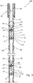
- the actuator comprises a cylinder 25, such as a hydraulic cylinder, having a cylinder chamber 26 in which a first end 27 of a cylinder shaft 28 is arranged and a second end 43 of the cylinder shaft is connected with the first part 8.
- a plunger 29 is arranged around the shaft, dividing the chamber into a first chamber part 41 and a second chamber part 42.
- the actuator further comprises a pump 44 providing pressurised fluid into one of the chamber parts through a first channel 61 for moving the cylinder shaft and the first part along the axial extension.
- the pump may pump fluid into the first chamber part 41 and simultaneously suck fluid out of the second chamber part 42 through a second channel 62.
- the shaft and the first part 8 are moved in a first direction away from the actuator, and by providing pressurised fluid in the second channel and thus into the second chamber part, the shaft is moved in a second direction opposite the first direction.
- the plunger may be part of the shaft.
- the housing comprises the plunger and is the moving part and the shaft is the stationary part.
- the downhole completion system comprises a plurality of openings in the production casing 2, a plurality of sleeves arranged opposite the openings and a plurality of sleeve controls 7, each sleeve control being arranged opposite a sleeve for opening, choking or closing the fluid communication through the opening.
- the sleeve controls 7 are not connected with each other and are only communicating wirelessly with each other, so that once the first sleeve control arranged nearest the top of the well receives a control signal to the next sleeve control arranged further down the production casing, the first sleeve control passes the signal on and the first communication module of the first sleeve control is thus used as a communication point.
- the downhole completion system comprises two sleeve controls 7 fastened to each other by means of a threaded shaft and a wireline/umbilical, so that the first communication module of the first sleeve control arranged nearest the top of the well communicates wirelessly to the second communication module, and the first communication module communicates to sleeve controls further down the well by means of the wireline/umbilical.
- the threaded shaft makes it possible to set and release all sleeve controls in one movement.
- Fig. 7 shows a cross-sectional view of the production casing 2 and the sleeve control 7 arranged therein when seen along the axial extension.
- the sleeve control 7 has a cross-sectional area D sc in a radial direction of the casing 2, which area is at least 50% smaller than a cross-sectional area D ci of the inside of the casing, preferably at least 45% smaller than the cross-sectional area of the inside of the casing, more preferably at least 35% smaller than the cross-sectional area of the inside of the casing.
- the smallest cross-sectional area D ci of the inside of the casing is, in this embodiment, the inside of the sleeve.
- the sleeve may be arranged in a circumferential recess in the casing, and then the smallest cross-sectional area D ci of the inside of the casing is the inner diameter of the casing.
- the downhole completion system 100 arranged in a borehole comprises a production casing 2 having an opening 4 for providing fluid communication from the borehole past the opening.
- the opening 4 is arranged inside the casing as a seat restricting the inner diameter of the casing.
- the downhole completion system 100 comprises, instead of a sleeve, a completion component 5 for opening, choking or closing the fluid communication.
- the completion component 5 has a profile 6 facing the inside of the casing.
- the downhole completion system 100 further comprises a component control 7 for opening, choking or closing the opening.
- the component control 7 comprises a first part 8 having a member 9 engaging the profile 6, and a second part 10.
- the second part 10 comprises a fixation unit 11 fixating the sleeve control 7 in the casing, an actuator 12 for moving the first part in relation to the second part, a power supply 14, such as a battery, supplying power to the actuator, and a first communication module 15 for receiving control signals from surface.
- the first part 8 has a conical part 71 matching the seat part 72 of the component 5, and when the first part is moved axially, the conical part 71 seats in the seat part 72 to close the opening 4.
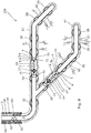
- the production casing 2 has a main production casing and a lateral production casing 81.
- the main production casing and the lateral production casing 81 both have an inflow control valve 82, and closer to the top the component controls 7 are arranged, so that fluid from the lower part of the production casings can be choked if not closed off.
- the lateral production casing 81 has the same size, i.e. the same inner diameter, as the main production casing 2, meaning that the lateral has the same inner diameter as the rest of the production casing.
- the lateral is a full bore lateral.
- Both the lateral and the main production casing have annular barriers 30 isolating several production zones, so that each zone is isolated between two adjacent annular barriers. Between the two annular barriers an inflow control valve 82 is arranged.
- the valves may include a fracturing port. If one production zone is producing too much water, the component control 7 closes that part of the production casing or the sleeve control 7 moves the sleeve 5 to close the opening.
- Such closing of part of the production casing or opening can be performed from surface by communicating with the first communication module of that control.
- the sleeve or component control can be released and retracted from the main production casing 2 or lateral production casing 81, providing full bore access of the casing, enabling access for all kinds of intervention tools.
- the completion system is re-completed by reinstalling the sleeve and/or component controls. So even though the completion system is intended for non-intervention wells, intervening the production casing is still possible.
- the controls can be updated especially in relation to software and battery, but also in relation to other parts.
- the downhole completion system 100 has a sleeve 5 movable by the sleeve control as in Fig. 2 .
- the first communication module 15 of the sleeve control is arranged in the fixation unit 11 abutting the restriction 39 and the inner face of the casing 2.
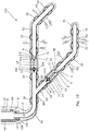
- the second communication module comprises a first communication unit 16a arranged on an outer face of the intermediate casing and a second communication unit 16b arranged on an inner face of the intermediate casing.
- the first communication unit and the second communication unit are electrically connected via electromagnetic induction and transfer signals and electrical power between them through the intermediate casing 19.
- the second communication module 16 comprises a third communication unit 16c connected with the second communication unit 16b by means of wiring or an electrical conductor, such as a cable, a cord or a wire.
- the third communication unit 16c is arranged on the outer face of the production casing further down the well opposite the first communication module 15.
- the third communication unit 16c of the second communication module 16 and first communication module 15 transfer signals and electrical power between them via electromagnetic induction through the production casing 2.
- the wiring 40 between the second communication unit 16b and the third communication unit 16c runs an annular barrier 30 in through one of the connection parts 51, connecting the expandable sleeve 33 with the tubular part 31, and past the space 37 and through the other connection part 51 further down the well, as illustrated in Fig. 11 .
- connection parts 51 may comprise connectors configured to connect to the wiring 40 and the connectors connect to an electrical conductor within the annular barrier in order that the wiring above and below is electrically connected through the connectors and the conductor.
- the wiring 40 may also extend through the annular barrier through a tube acting as a tunnel through the space between the expandable sleeve and the tubular part 31.
- the downhole completion system 100 comprises completion components 5 where a first part 5a of the completion component is the at least one member 9 engaging the profile 6 of a second part 5b of the completion component.
- the first part 5a of the completion component is arranged at the component control 7.
- the first communication module 15 of the component control 7 is arranged in the fixation unit 11 abutting the restriction 39 and the inner face of the casing 2.
- the second communication module 16 comprises a first communication unit 16a arranged on an outer face of the intermediate casing and a second communication unit 16b arranged on an inner face of the intermediate casing.
- the first communication unit 16a is electrically connected to surface via wiring 40 extending through the main barrier 65.
- the first communication unit 16a and the second communication unit 16b are electrically connected via electromagnetic induction and transfer signals and electrical power between them through the intermediate casing.
- the second communication module 16 comprises a third communication unit 16c connected with the second communication unit 16b by means of wiring or an electrical conductor, such as a cable, a cord or a wire.
- the third communication unit 16c is arranged on the outer face of the production casing further down the well but above the lateral production casing 81.
- the second communication module 16 comprises a fourth communication unit 16d arranged opposite the first communication module 15.
- the third and fourth communication units are electrically connected via wiring 40.
- the fourth communication unit 16c of the second communication module 16 and first communication module 15 transfer signals and electrical power between them via electromagnetic induction through the production casing 2.
- the third communication unit 16c is furthermore electrically connected with a fifth communication unit 16e arranged outside the main casing which is the production casing 2.
- the fifth communication unit 16e is arranged opposite a first communication module 15 of another component control 7 in the main casing and transfers signals and power by means of electromagnetic induction through the production casing 2.
- Both the wiring 40 between the second communication unit 16b and the third communication unit 16c and between the third communication unit 16c and the fourth communication unit 16d run past an annular barrier 30.
- the wiring 40 extends in through one of the connection parts 51 connecting the expandable sleeve 33 with the tubular part 31 and past the space 37 and through the other connection part 51 further down the well as illustrated in Fig. 11 .
- the wiring 40 of Fig. 10 between the third communication unit 16c and the fifth communication unit 16e extends past the lateral production casing 81 on the outside of the main casing and through the annular barrier 30 arranged further down the main casing.
- All the communication units each comprises an inductive coupler for transferring power from one communication unit to another through the casing by means of electromagnetic induction.
- the casing may have non-magnetic sections opposite the communication units to optimise the transfer by electromagnetic induction.
- fluid or well fluid any kind of fluid that may be present in oil or gas wells downhole, such as natural gas, oil, oil mud, crude oil, water, etc.
- gas is meant any kind of gas composition present in a well, completion, or open hole
- oil is meant any kind of oil composition, such as crude oil, an oil-containing fluid, etc.
- Gas, oil, and water fluids may thus all comprise other elements or substances than gas, oil, and/or water, respectively.
- a casing By a casing, a production casing, an intermediate casing, tubular part or well tubular structure is meant any kind of pipe, tubing, tubular, liner, string etc. fixedly installed downhole in relation to oil or natural gas production and through which the oil or gas flows.
- a downhole tractor can be used to push the tool all the way into position in the well.
- the downhole tractor may have projectable arms having wheels, wherein the wheels contact the inner surface of the casing for propelling the tractor and the tool forward in the casing.
- a downhole tractor is any kind of driving tool capable of pushing or pulling tools in a well downhole, such as a Well Tractor®.
Landscapes
- Life Sciences & Earth Sciences (AREA)
- Engineering & Computer Science (AREA)
- Geology (AREA)
- Mining & Mineral Resources (AREA)
- Physics & Mathematics (AREA)
- Environmental & Geological Engineering (AREA)
- Fluid Mechanics (AREA)
- General Life Sciences & Earth Sciences (AREA)
- Geochemistry & Mineralogy (AREA)
- Earth Drilling (AREA)
- Laying Of Electric Cables Or Lines Outside (AREA)
Claims (15)
- Bohrloch-Komplettierungssystem (100), das in einem Bohrloch angeordnet ist, Folgendes umfassend:- eine Produktionsverrohrung (2), die Folgendes hat: eine axiale Ausdehnung, ein Inneres (3), einen Innendurchmesser (Di) und eine Öffnung (4) zum Bereitstellen einer Fluidkommunikation zwischen dem Bohrloch und dem Inneren,- eine Buchse oder eine Komplettierungskomponente (5), die wenigstens teilweise entlang der axialen Ausdehnung beweglich oder um diese drehbar eingerichtet ist, wobei die Buchse oder Komplettierungskomponente auf Höhe der Öffnung angeordnet ist, um die Fluidkommunikation zu öffnen, drosseln oder schließen, wobei die Buchse ein Profil (6) hat, das dem Inneren der Verrohrung zugewandt ist, und- eine Buchsensteuerung (7) zum Bewegen der Buchse für das Öffnen, Drosseln oder Verschließen der Öffnung,wobei die Buchsensteuerung Folgendes umfasst:- einen ersten Teil (8), der wenigstens ein Element (9) umfasst, das in das Profil eingreift,- einen zweiten Teil (10), der Folgendes umfasst:- eine Fixierungseinheit (11), die die Buchsensteuerung in der Verrohrung fixiert,- einen Aktor (12), um den ersten Teil relativ zum zweiten Teil zu bewegen,- eine Energieversorgung (14), wie etwa eine Batterie, die den Aktor mit Energie versorgt, und- ein erstes Kommunikationsmodul (15), um von der Oberfläche Steuersignale zu empfangen.
- Bohrloch-Komplettierungssystem nach Anspruch 1, das außerdem ein zweites Kommunikationsmodul (16) zur Kommunikation mit dem ersten Kommunikationsmodul umfasst.
- Bohrloch-Komplettierungssystem nach Anspruch 1 oder 2, wobei das zweite Kommunikationsmodul eine erste Kommunikationseinheit (16a) und eine zweite Kommunikationseinheit (16b) umfasst.
- Bohrloch-Komplettierungssystem nach Anspruch 3, wobei die erste Kommunikationseinheit und die zweite Kommunikationseinheit über elektromagnetische Induktion elektrisch miteinander verbunden sind.
- Bohrloch-Komplettierungssystem nach einem der vorhergehenden Ansprüche, wobei ein erster Teil (5a) der Komplettierungskomponente das wenigstens eine Element (9) ist, das in das Profil eines zweiten Teils (5b) der Komplettierungskomponente eingreift.
- Bohrloch-Komplettierungssystem nach Anspruch 1 oder 2, wobei das zweite Kommunikationsmodul in der Nähe eines oberen Endes (17) des Bohrlochs angeordnet ist, eingetaucht in einen Ring (18) zwischen der Produktionsverrohrung und einer Wand des Bohrlochs oder einer Zwischenverrohrung (19), oder mit der Produktionsverrohrung verbunden ist.
- Bohrloch-Komplettierungssystem nach einem der vorhergehenden Ansprüche, wobei das erste und zweite Kommunikationsmodul drahtlos mittels Schlammimpulsen, einem elektrischen Feld, elektromagnetischer Induktion oder Schallwellen kommunizieren.
- Bohrloch-Komplettierungssystem nach Anspruch 7, wobei die Energieversorgung wieder aufladbar ist und aufgeladen wird, indem das erste Kommunikationsmodul die Schlammimpulse, ein elektrisches Feld oder Schallwellen in elektrische Energie wandelt, oder durch das Übertragen elektromagnetischer Induktion.
- Bohrloch-Komplettierungssystem nach einem der vorhergehenden Ansprüche, wobei die Fixierungseinheit Fixierungselemente (20) hat, die sich radial in Richtung der Produktionsverrohrung erstrecken.
- Bohrloch-Komplettierungssystem nach einem der vorhergehenden Ansprüche, wobei der Aktor einen Elektromotor (23) umfasst, der von der Energieversorgung mit Energie versorgt wird, sowie eine Getriebeeinrichtung (24), die vom Motor angetrieben wird, um den ersten Teil zu bewegen.
- Bohrloch-Komplettierungssystem nach Anspruch 10, wobei die Getriebeeinrichtung ein Schneckengetriebe ist, das eine axiale Bewegung des ersten Teils relativ zum zweiten Teil bereitstellt.
- Bohrloch-Komplettierungssystem nach Anspruch 10, wobei die Getriebeeinrichtung wenigstens eine Getriebezahnrad umfasst, um den ersten Teil relativ zum zweiten Teil zu drehen.
- Bohrloch-Komplettierungssystem nach Anspruch 1, wobei der Aktor außerdem einen Elektromotor (23) umfasst, der von der Energieversorgung mit Energie versorgt wird, sowie einen Zylinder (25), der eine Zylinderkammer (26) hat, in der ein erstes Ende (27) einer Zylinderstange (28) angeordnet ist, wobei ein mit der Stange verbundener Kolben (29) die Kammer in einen ersten Kammerteil (41) und einen zweiten Kammerteil (42) unterteilt und wobei ein zweites Ende (43) der Zylinderstange mit dem ersten Teil verbunden ist, wobei der Aktor außerdem eine Pumpe (44) umfasst, die unter Druck stehendes Fluid in einen der beiden Kammerteile zuführt, um die Zylinderstange und den ersten Teil entlang der axialen Ausdehnung zu bewegen.
- Bohrloch-Komplettierungssystem nach einem der vorhergehenden Ansprüche, wobei das Bohrloch-Komplettierungssystem mehrere Öffnungen in der Produktionsverrohrung, mehrere Buchsen, die auf Höhe der Öffnungen angeordnet sind, und mehrere Buchsensteuerungen umfasst, wobei jede Buchsensteuerung auf Höhe einer Buchse angeordnet ist, um die Fluidkommunikation durch die Öffnung zu öffnen, zu drosseln oder zu schließen.
- Bohrloch-Komplettierungssystem nach Anspruch 14, wobei die ersten Kommunikationsmodule der Buchsensteuerungen untereinander kommunizieren können.
Applications Claiming Priority (2)
| Application Number | Priority Date | Filing Date | Title |
|---|---|---|---|
| EP14195722.5A EP3029265A1 (de) | 2014-12-01 | 2014-12-01 | Bohrlochabschlusssystem |
| PCT/EP2015/078213 WO2016087441A1 (en) | 2014-12-01 | 2015-12-01 | Downhole completion system |
Publications (2)
| Publication Number | Publication Date |
|---|---|
| EP3227526A1 EP3227526A1 (de) | 2017-10-11 |
| EP3227526B1 true EP3227526B1 (de) | 2019-08-14 |
Family
ID=52000744
Family Applications (2)
| Application Number | Title | Priority Date | Filing Date |
|---|---|---|---|
| EP14195722.5A Withdrawn EP3029265A1 (de) | 2014-12-01 | 2014-12-01 | Bohrlochabschlusssystem |
| EP15802128.7A Active EP3227526B1 (de) | 2014-12-01 | 2015-12-01 | Bohrlochabschlusssystem |
Family Applications Before (1)
| Application Number | Title | Priority Date | Filing Date |
|---|---|---|---|
| EP14195722.5A Withdrawn EP3029265A1 (de) | 2014-12-01 | 2014-12-01 | Bohrlochabschlusssystem |
Country Status (5)
| Country | Link |
|---|---|
| US (1) | US10597975B2 (de) |
| EP (2) | EP3029265A1 (de) |
| BR (1) | BR112017009865B1 (de) |
| DK (1) | DK3227526T3 (de) |
| WO (1) | WO2016087441A1 (de) |
Families Citing this family (1)
| Publication number | Priority date | Publication date | Assignee | Title |
|---|---|---|---|---|
| CN112814636B (zh) * | 2020-12-24 | 2023-02-03 | 荆州市威克石油机械设备有限公司 | 一种低频压裂装置 |
Family Cites Families (6)
| Publication number | Priority date | Publication date | Assignee | Title |
|---|---|---|---|---|
| EP2458137B1 (de) * | 2010-11-24 | 2018-11-14 | Welltec A/S | Drahtlose Bohrlochvorrichtung |
| GB201120448D0 (en) * | 2011-11-28 | 2012-01-11 | Oilsco Technologies Ltd | Apparatus and method |
| GB201205985D0 (en) * | 2012-04-03 | 2012-05-16 | Petrowell Ltd | Frac packing tools |
| BR112015008913B1 (pt) * | 2012-10-26 | 2021-07-27 | Halliburton Energy Services, Inc. | Válvula de inserção semiautônoma |
| US9587486B2 (en) * | 2013-02-28 | 2017-03-07 | Halliburton Energy Services, Inc. | Method and apparatus for magnetic pulse signature actuation |
| US9759040B2 (en) * | 2013-12-20 | 2017-09-12 | Weatherford Technology Holdings, Llc | Autonomous selective shifting tool |
-
2014
- 2014-12-01 EP EP14195722.5A patent/EP3029265A1/de not_active Withdrawn
-
2015
- 2015-12-01 DK DK15802128T patent/DK3227526T3/da active
- 2015-12-01 EP EP15802128.7A patent/EP3227526B1/de active Active
- 2015-12-01 WO PCT/EP2015/078213 patent/WO2016087441A1/en not_active Ceased
- 2015-12-01 BR BR112017009865-2A patent/BR112017009865B1/pt active IP Right Grant
- 2015-12-01 US US15/529,716 patent/US10597975B2/en active Active
Non-Patent Citations (1)
| Title |
|---|
| None * |
Also Published As
| Publication number | Publication date |
|---|---|
| WO2016087441A1 (en) | 2016-06-09 |
| US20170328173A1 (en) | 2017-11-16 |
| EP3227526A1 (de) | 2017-10-11 |
| BR112017009865A2 (pt) | 2017-12-19 |
| DK3227526T3 (da) | 2019-11-18 |
| US10597975B2 (en) | 2020-03-24 |
| EP3029265A1 (de) | 2016-06-08 |
| BR112017009865B1 (pt) | 2022-08-02 |
Similar Documents
| Publication | Publication Date | Title |
|---|---|---|
| US7677320B2 (en) | Subsea well with electrical submersible pump above downhole safety valve | |
| US8157015B2 (en) | Large bore vertical tree | |
| CA2586192C (en) | Safety valve | |
| SG177893A1 (en) | Open water recoverable drilling protector | |
| NO20161876A1 (en) | Downhole equipment suspension and lateral power system | |
| US20140158371A1 (en) | Disconnecting tool | |
| WO2015172921A1 (en) | Downhole equipment suspension and power system | |
| US20180230767A1 (en) | Method and Apparatus for Reducing Downhole Losses in Drilling Operations, Sticking Prevention, and Hole Cleaning Enhancement | |
| EP3380698B1 (de) | Mit einem elektrischen leiter augestattete ringförmige bohrlochabsperrungsanordnung | |
| RU2587205C2 (ru) | Поршневая тянущая система, используемая в подземных скважинах | |
| GB2522874A (en) | Milling apparatus | |
| US10145212B2 (en) | Hydraulically assisted deployed ESP system | |
| EP3227526B1 (de) | Bohrlochabschlusssystem | |
| CN110168189B (zh) | 用于脐带缆部署式电潜泵的地下悬挂器 | |
| US20170167231A1 (en) | Methods and Systems Employing an Electrically-Powered Crossover Service Tool | |
| EP3187682A1 (de) | Mit einem elektrischen leiter augestattete ringförmige bohrlochabsperrungsanordnung | |
| WO2019136242A1 (en) | Hydraulically assisted deployed esp system | |
| DK202070374A8 (en) | Apparatus for performing multiple downhole operations in a production tubing |
Legal Events
| Date | Code | Title | Description |
|---|---|---|---|
| STAA | Information on the status of an ep patent application or granted ep patent |
Free format text: STATUS: THE INTERNATIONAL PUBLICATION HAS BEEN MADE |
|
| PUAI | Public reference made under article 153(3) epc to a published international application that has entered the european phase |
Free format text: ORIGINAL CODE: 0009012 |
|
| STAA | Information on the status of an ep patent application or granted ep patent |
Free format text: STATUS: REQUEST FOR EXAMINATION WAS MADE |
|
| 17P | Request for examination filed |
Effective date: 20170607 |
|
| AK | Designated contracting states |
Kind code of ref document: A1 Designated state(s): AL AT BE BG CH CY CZ DE DK EE ES FI FR GB GR HR HU IE IS IT LI LT LU LV MC MK MT NL NO PL PT RO RS SE SI SK SM TR |
|
| AX | Request for extension of the european patent |
Extension state: BA ME |
|
| DAV | Request for validation of the european patent (deleted) | ||
| DAX | Request for extension of the european patent (deleted) | ||
| REG | Reference to a national code |
Ref country code: DE Ref legal event code: R079 Ref document number: 602015035941 Country of ref document: DE Free format text: PREVIOUS MAIN CLASS: E21B0034060000 Ipc: E21B0023040000 |
|
| RIC1 | Information provided on ipc code assigned before grant |
Ipc: E21B 34/14 20060101ALI20180615BHEP Ipc: E21B 33/128 20060101ALI20180615BHEP Ipc: E21B 34/00 20060101ALI20180615BHEP Ipc: E21B 23/06 20060101ALI20180615BHEP Ipc: E21B 23/04 20060101AFI20180615BHEP Ipc: E21B 34/06 20060101ALI20180615BHEP |
|
| GRAP | Despatch of communication of intention to grant a patent |
Free format text: ORIGINAL CODE: EPIDOSNIGR1 |
|
| STAA | Information on the status of an ep patent application or granted ep patent |
Free format text: STATUS: GRANT OF PATENT IS INTENDED |
|
| INTG | Intention to grant announced |
Effective date: 20181001 |
|
| RAP1 | Party data changed (applicant data changed or rights of an application transferred) |
Owner name: WELLTEC OILFIELD SOLUTIONS AG |
|
| GRAS | Grant fee paid |
Free format text: ORIGINAL CODE: EPIDOSNIGR3 |
|
| GRAJ | Information related to disapproval of communication of intention to grant by the applicant or resumption of examination proceedings by the epo deleted |
Free format text: ORIGINAL CODE: EPIDOSDIGR1 |
|
| GRAL | Information related to payment of fee for publishing/printing deleted |
Free format text: ORIGINAL CODE: EPIDOSDIGR3 |
|
| STAA | Information on the status of an ep patent application or granted ep patent |
Free format text: STATUS: REQUEST FOR EXAMINATION WAS MADE |
|
| INTC | Intention to grant announced (deleted) | ||
| GRAP | Despatch of communication of intention to grant a patent |
Free format text: ORIGINAL CODE: EPIDOSNIGR1 |
|
| STAA | Information on the status of an ep patent application or granted ep patent |
Free format text: STATUS: GRANT OF PATENT IS INTENDED |
|
| INTG | Intention to grant announced |
Effective date: 20190318 |
|
| GRAA | (expected) grant |
Free format text: ORIGINAL CODE: 0009210 |
|
| STAA | Information on the status of an ep patent application or granted ep patent |
Free format text: STATUS: THE PATENT HAS BEEN GRANTED |
|
| AK | Designated contracting states |
Kind code of ref document: B1 Designated state(s): AL AT BE BG CH CY CZ DE DK EE ES FI FR GB GR HR HU IE IS IT LI LT LU LV MC MK MT NL NO PL PT RO RS SE SI SK SM TR |
|
| REG | Reference to a national code |
Ref country code: GB Ref legal event code: FG4D |
|
| REG | Reference to a national code |
Ref country code: CH Ref legal event code: EP Ref country code: AT Ref legal event code: REF Ref document number: 1167243 Country of ref document: AT Kind code of ref document: T Effective date: 20190815 |
|
| REG | Reference to a national code |
Ref country code: IE Ref legal event code: FG4D |
|
| REG | Reference to a national code |
Ref country code: DE Ref legal event code: R096 Ref document number: 602015035941 Country of ref document: DE |
|
| REG | Reference to a national code |
Ref country code: NO Ref legal event code: T2 Effective date: 20190814 |
|
| REG | Reference to a national code |
Ref country code: NL Ref legal event code: FP |
|
| REG | Reference to a national code |
Ref country code: DK Ref legal event code: T3 Effective date: 20191114 |
|
| REG | Reference to a national code |
Ref country code: LT Ref legal event code: MG4D |
|
| PG25 | Lapsed in a contracting state [announced via postgrant information from national office to epo] |
Ref country code: HR Free format text: LAPSE BECAUSE OF FAILURE TO SUBMIT A TRANSLATION OF THE DESCRIPTION OR TO PAY THE FEE WITHIN THE PRESCRIBED TIME-LIMIT Effective date: 20190814 Ref country code: FI Free format text: LAPSE BECAUSE OF FAILURE TO SUBMIT A TRANSLATION OF THE DESCRIPTION OR TO PAY THE FEE WITHIN THE PRESCRIBED TIME-LIMIT Effective date: 20190814 Ref country code: LT Free format text: LAPSE BECAUSE OF FAILURE TO SUBMIT A TRANSLATION OF THE DESCRIPTION OR TO PAY THE FEE WITHIN THE PRESCRIBED TIME-LIMIT Effective date: 20190814 Ref country code: SE Free format text: LAPSE BECAUSE OF FAILURE TO SUBMIT A TRANSLATION OF THE DESCRIPTION OR TO PAY THE FEE WITHIN THE PRESCRIBED TIME-LIMIT Effective date: 20190814 Ref country code: PT Free format text: LAPSE BECAUSE OF FAILURE TO SUBMIT A TRANSLATION OF THE DESCRIPTION OR TO PAY THE FEE WITHIN THE PRESCRIBED TIME-LIMIT Effective date: 20191216 Ref country code: BG Free format text: LAPSE BECAUSE OF FAILURE TO SUBMIT A TRANSLATION OF THE DESCRIPTION OR TO PAY THE FEE WITHIN THE PRESCRIBED TIME-LIMIT Effective date: 20191114 |
|
| REG | Reference to a national code |
Ref country code: AT Ref legal event code: MK05 Ref document number: 1167243 Country of ref document: AT Kind code of ref document: T Effective date: 20190814 |
|
| PG25 | Lapsed in a contracting state [announced via postgrant information from national office to epo] |
Ref country code: LV Free format text: LAPSE BECAUSE OF FAILURE TO SUBMIT A TRANSLATION OF THE DESCRIPTION OR TO PAY THE FEE WITHIN THE PRESCRIBED TIME-LIMIT Effective date: 20190814 Ref country code: AL Free format text: LAPSE BECAUSE OF FAILURE TO SUBMIT A TRANSLATION OF THE DESCRIPTION OR TO PAY THE FEE WITHIN THE PRESCRIBED TIME-LIMIT Effective date: 20190814 Ref country code: GR Free format text: LAPSE BECAUSE OF FAILURE TO SUBMIT A TRANSLATION OF THE DESCRIPTION OR TO PAY THE FEE WITHIN THE PRESCRIBED TIME-LIMIT Effective date: 20191115 Ref country code: RS Free format text: LAPSE BECAUSE OF FAILURE TO SUBMIT A TRANSLATION OF THE DESCRIPTION OR TO PAY THE FEE WITHIN THE PRESCRIBED TIME-LIMIT Effective date: 20190814 Ref country code: IS Free format text: LAPSE BECAUSE OF FAILURE TO SUBMIT A TRANSLATION OF THE DESCRIPTION OR TO PAY THE FEE WITHIN THE PRESCRIBED TIME-LIMIT Effective date: 20191214 |
|
| PG25 | Lapsed in a contracting state [announced via postgrant information from national office to epo] |
Ref country code: TR Free format text: LAPSE BECAUSE OF FAILURE TO SUBMIT A TRANSLATION OF THE DESCRIPTION OR TO PAY THE FEE WITHIN THE PRESCRIBED TIME-LIMIT Effective date: 20190814 |
|
| RAP2 | Party data changed (patent owner data changed or rights of a patent transferred) |
Owner name: WELLTEC OILFIELD SOLUTIONS AG |
|
| PG25 | Lapsed in a contracting state [announced via postgrant information from national office to epo] |
Ref country code: PL Free format text: LAPSE BECAUSE OF FAILURE TO SUBMIT A TRANSLATION OF THE DESCRIPTION OR TO PAY THE FEE WITHIN THE PRESCRIBED TIME-LIMIT Effective date: 20190814 Ref country code: EE Free format text: LAPSE BECAUSE OF FAILURE TO SUBMIT A TRANSLATION OF THE DESCRIPTION OR TO PAY THE FEE WITHIN THE PRESCRIBED TIME-LIMIT Effective date: 20190814 Ref country code: AT Free format text: LAPSE BECAUSE OF FAILURE TO SUBMIT A TRANSLATION OF THE DESCRIPTION OR TO PAY THE FEE WITHIN THE PRESCRIBED TIME-LIMIT Effective date: 20190814 Ref country code: IT Free format text: LAPSE BECAUSE OF FAILURE TO SUBMIT A TRANSLATION OF THE DESCRIPTION OR TO PAY THE FEE WITHIN THE PRESCRIBED TIME-LIMIT Effective date: 20190814 Ref country code: RO Free format text: LAPSE BECAUSE OF FAILURE TO SUBMIT A TRANSLATION OF THE DESCRIPTION OR TO PAY THE FEE WITHIN THE PRESCRIBED TIME-LIMIT Effective date: 20190814 |
|
| PG25 | Lapsed in a contracting state [announced via postgrant information from national office to epo] |
Ref country code: SM Free format text: LAPSE BECAUSE OF FAILURE TO SUBMIT A TRANSLATION OF THE DESCRIPTION OR TO PAY THE FEE WITHIN THE PRESCRIBED TIME-LIMIT Effective date: 20190814 Ref country code: SK Free format text: LAPSE BECAUSE OF FAILURE TO SUBMIT A TRANSLATION OF THE DESCRIPTION OR TO PAY THE FEE WITHIN THE PRESCRIBED TIME-LIMIT Effective date: 20190814 Ref country code: IS Free format text: LAPSE BECAUSE OF FAILURE TO SUBMIT A TRANSLATION OF THE DESCRIPTION OR TO PAY THE FEE WITHIN THE PRESCRIBED TIME-LIMIT Effective date: 20200224 Ref country code: CZ Free format text: LAPSE BECAUSE OF FAILURE TO SUBMIT A TRANSLATION OF THE DESCRIPTION OR TO PAY THE FEE WITHIN THE PRESCRIBED TIME-LIMIT Effective date: 20190814 |
|
| REG | Reference to a national code |
Ref country code: DE Ref legal event code: R097 Ref document number: 602015035941 Country of ref document: DE |
|
| PLBE | No opposition filed within time limit |
Free format text: ORIGINAL CODE: 0009261 |
|
| STAA | Information on the status of an ep patent application or granted ep patent |
Free format text: STATUS: NO OPPOSITION FILED WITHIN TIME LIMIT |
|
| PG2D | Information on lapse in contracting state deleted |
Ref country code: IS |
|
| REG | Reference to a national code |
Ref country code: CH Ref legal event code: PL |
|
| 26N | No opposition filed |
Effective date: 20200603 |
|
| REG | Reference to a national code |
Ref country code: BE Ref legal event code: MM Effective date: 20191231 |
|
| PG25 | Lapsed in a contracting state [announced via postgrant information from national office to epo] |
Ref country code: SI Free format text: LAPSE BECAUSE OF FAILURE TO SUBMIT A TRANSLATION OF THE DESCRIPTION OR TO PAY THE FEE WITHIN THE PRESCRIBED TIME-LIMIT Effective date: 20190814 Ref country code: MC Free format text: LAPSE BECAUSE OF FAILURE TO SUBMIT A TRANSLATION OF THE DESCRIPTION OR TO PAY THE FEE WITHIN THE PRESCRIBED TIME-LIMIT Effective date: 20190814 |
|
| PG25 | Lapsed in a contracting state [announced via postgrant information from national office to epo] |
Ref country code: LU Free format text: LAPSE BECAUSE OF NON-PAYMENT OF DUE FEES Effective date: 20191201 Ref country code: ES Free format text: LAPSE BECAUSE OF FAILURE TO SUBMIT A TRANSLATION OF THE DESCRIPTION OR TO PAY THE FEE WITHIN THE PRESCRIBED TIME-LIMIT Effective date: 20190814 Ref country code: IE Free format text: LAPSE BECAUSE OF NON-PAYMENT OF DUE FEES Effective date: 20191201 |
|
| PG25 | Lapsed in a contracting state [announced via postgrant information from national office to epo] |
Ref country code: LI Free format text: LAPSE BECAUSE OF NON-PAYMENT OF DUE FEES Effective date: 20191231 Ref country code: BE Free format text: LAPSE BECAUSE OF NON-PAYMENT OF DUE FEES Effective date: 20191231 Ref country code: CH Free format text: LAPSE BECAUSE OF NON-PAYMENT OF DUE FEES Effective date: 20191231 |
|
| PGFP | Annual fee paid to national office [announced via postgrant information from national office to epo] |
Ref country code: NL Payment date: 20201221 Year of fee payment: 6 |
|
| PG25 | Lapsed in a contracting state [announced via postgrant information from national office to epo] |
Ref country code: CY Free format text: LAPSE BECAUSE OF FAILURE TO SUBMIT A TRANSLATION OF THE DESCRIPTION OR TO PAY THE FEE WITHIN THE PRESCRIBED TIME-LIMIT Effective date: 20190814 |
|
| PGFP | Annual fee paid to national office [announced via postgrant information from national office to epo] |
Ref country code: DE Payment date: 20201221 Year of fee payment: 6 |
|
| PG25 | Lapsed in a contracting state [announced via postgrant information from national office to epo] |
Ref country code: MT Free format text: LAPSE BECAUSE OF FAILURE TO SUBMIT A TRANSLATION OF THE DESCRIPTION OR TO PAY THE FEE WITHIN THE PRESCRIBED TIME-LIMIT Effective date: 20190814 Ref country code: HU Free format text: LAPSE BECAUSE OF FAILURE TO SUBMIT A TRANSLATION OF THE DESCRIPTION OR TO PAY THE FEE WITHIN THE PRESCRIBED TIME-LIMIT; INVALID AB INITIO Effective date: 20151201 |
|
| PG25 | Lapsed in a contracting state [announced via postgrant information from national office to epo] |
Ref country code: MK Free format text: LAPSE BECAUSE OF FAILURE TO SUBMIT A TRANSLATION OF THE DESCRIPTION OR TO PAY THE FEE WITHIN THE PRESCRIBED TIME-LIMIT Effective date: 20190814 |
|
| REG | Reference to a national code |
Ref country code: DE Ref legal event code: R119 Ref document number: 602015035941 Country of ref document: DE |
|
| REG | Reference to a national code |
Ref country code: NL Ref legal event code: MM Effective date: 20220101 |
|
| PG25 | Lapsed in a contracting state [announced via postgrant information from national office to epo] |
Ref country code: NL Free format text: LAPSE BECAUSE OF NON-PAYMENT OF DUE FEES Effective date: 20220101 |
|
| PG25 | Lapsed in a contracting state [announced via postgrant information from national office to epo] |
Ref country code: DE Free format text: LAPSE BECAUSE OF NON-PAYMENT OF DUE FEES Effective date: 20220701 |
|
| P01 | Opt-out of the competence of the unified patent court (upc) registered |
Effective date: 20230523 |
|
| REG | Reference to a national code |
Ref country code: GB Ref legal event code: 732E Free format text: REGISTERED BETWEEN 20241017 AND 20241023 |
|
| PGFP | Annual fee paid to national office [announced via postgrant information from national office to epo] |
Ref country code: GB Payment date: 20251219 Year of fee payment: 11 |
|
| PGFP | Annual fee paid to national office [announced via postgrant information from national office to epo] |
Ref country code: NO Payment date: 20251219 Year of fee payment: 11 |
|
| PGFP | Annual fee paid to national office [announced via postgrant information from national office to epo] |
Ref country code: DK Payment date: 20251222 Year of fee payment: 11 |
|
| PGFP | Annual fee paid to national office [announced via postgrant information from national office to epo] |
Ref country code: FR Payment date: 20251211 Year of fee payment: 11 |