EP3380698B1 - Mit einem elektrischen leiter augestattete ringförmige bohrlochabsperrungsanordnung - Google Patents
Mit einem elektrischen leiter augestattete ringförmige bohrlochabsperrungsanordnung Download PDFInfo
- Publication number
- EP3380698B1 EP3380698B1 EP16798530.8A EP16798530A EP3380698B1 EP 3380698 B1 EP3380698 B1 EP 3380698B1 EP 16798530 A EP16798530 A EP 16798530A EP 3380698 B1 EP3380698 B1 EP 3380698B1
- Authority
- EP
- European Patent Office
- Prior art keywords
- tubular structure
- well
- well tubular
- electrical
- downhole system
- Prior art date
- Legal status (The legal status is an assumption and is not a legal conclusion. Google has not performed a legal analysis and makes no representation as to the accuracy of the status listed.)
- Active
Links
Images




Classifications
-
- E—FIXED CONSTRUCTIONS
- E21—EARTH OR ROCK DRILLING; MINING
- E21B—EARTH OR ROCK DRILLING; OBTAINING OIL, GAS, WATER, SOLUBLE OR MELTABLE MATERIALS OR A SLURRY OF MINERALS FROM WELLS
- E21B33/00—Sealing or packing boreholes or wells
- E21B33/10—Sealing or packing boreholes or wells in the borehole
- E21B33/12—Packers; Plugs
- E21B33/127—Packers; Plugs with inflatable sleeve
-
- E—FIXED CONSTRUCTIONS
- E21—EARTH OR ROCK DRILLING; MINING
- E21B—EARTH OR ROCK DRILLING; OBTAINING OIL, GAS, WATER, SOLUBLE OR MELTABLE MATERIALS OR A SLURRY OF MINERALS FROM WELLS
- E21B33/00—Sealing or packing boreholes or wells
- E21B33/10—Sealing or packing boreholes or wells in the borehole
- E21B33/12—Packers; Plugs
-
- E—FIXED CONSTRUCTIONS
- E21—EARTH OR ROCK DRILLING; MINING
- E21B—EARTH OR ROCK DRILLING; OBTAINING OIL, GAS, WATER, SOLUBLE OR MELTABLE MATERIALS OR A SLURRY OF MINERALS FROM WELLS
- E21B17/00—Drilling rods or pipes; Flexible drill strings; Kellies; Drill collars; Sucker rods; Cables; Casings; Tubings
- E21B17/003—Drilling rods or pipes; Flexible drill strings; Kellies; Drill collars; Sucker rods; Cables; Casings; Tubings with electrically conducting or insulating means
-
- E—FIXED CONSTRUCTIONS
- E21—EARTH OR ROCK DRILLING; MINING
- E21B—EARTH OR ROCK DRILLING; OBTAINING OIL, GAS, WATER, SOLUBLE OR MELTABLE MATERIALS OR A SLURRY OF MINERALS FROM WELLS
- E21B17/00—Drilling rods or pipes; Flexible drill strings; Kellies; Drill collars; Sucker rods; Cables; Casings; Tubings
- E21B17/02—Couplings; joints
- E21B17/023—Arrangements for connecting cables or wirelines to downhole devices
- E21B17/026—Arrangements for fixing cables or wirelines to the outside of downhole devices
-
- E—FIXED CONSTRUCTIONS
- E21—EARTH OR ROCK DRILLING; MINING
- E21B—EARTH OR ROCK DRILLING; OBTAINING OIL, GAS, WATER, SOLUBLE OR MELTABLE MATERIALS OR A SLURRY OF MINERALS FROM WELLS
- E21B17/00—Drilling rods or pipes; Flexible drill strings; Kellies; Drill collars; Sucker rods; Cables; Casings; Tubings
- E21B17/02—Couplings; joints
- E21B17/028—Electrical or electro-magnetic connections
- E21B17/0283—Electrical or electro-magnetic connections characterised by the coupling being contactless, e.g. inductive
-
- E—FIXED CONSTRUCTIONS
- E21—EARTH OR ROCK DRILLING; MINING
- E21B—EARTH OR ROCK DRILLING; OBTAINING OIL, GAS, WATER, SOLUBLE OR MELTABLE MATERIALS OR A SLURRY OF MINERALS FROM WELLS
- E21B41/00—Equipment or details not covered by groups E21B15/00 - E21B40/00
- E21B41/0035—Apparatus or methods for multilateral well technology, e.g. for the completion of or workover on wells with one or more lateral branches
-
- E—FIXED CONSTRUCTIONS
- E21—EARTH OR ROCK DRILLING; MINING
- E21B—EARTH OR ROCK DRILLING; OBTAINING OIL, GAS, WATER, SOLUBLE OR MELTABLE MATERIALS OR A SLURRY OF MINERALS FROM WELLS
- E21B43/00—Methods or apparatus for obtaining oil, gas, water, soluble or meltable materials or a slurry of minerals from wells
- E21B43/14—Obtaining from a multiple-zone well
-
- E—FIXED CONSTRUCTIONS
- E21—EARTH OR ROCK DRILLING; MINING
- E21B—EARTH OR ROCK DRILLING; OBTAINING OIL, GAS, WATER, SOLUBLE OR MELTABLE MATERIALS OR A SLURRY OF MINERALS FROM WELLS
- E21B47/00—Survey of boreholes or wells
-
- E—FIXED CONSTRUCTIONS
- E21—EARTH OR ROCK DRILLING; MINING
- E21B—EARTH OR ROCK DRILLING; OBTAINING OIL, GAS, WATER, SOLUBLE OR MELTABLE MATERIALS OR A SLURRY OF MINERALS FROM WELLS
- E21B47/00—Survey of boreholes or wells
- E21B47/12—Means for transmitting measuring-signals or control signals from the well to the surface, or from the surface to the well, e.g. for logging while drilling
- E21B47/13—Means for transmitting measuring-signals or control signals from the well to the surface, or from the surface to the well, e.g. for logging while drilling by electromagnetic energy, e.g. radio frequency
-
- E—FIXED CONSTRUCTIONS
- E21—EARTH OR ROCK DRILLING; MINING
- E21B—EARTH OR ROCK DRILLING; OBTAINING OIL, GAS, WATER, SOLUBLE OR MELTABLE MATERIALS OR A SLURRY OF MINERALS FROM WELLS
- E21B2200/00—Special features related to earth drilling for obtaining oil, gas or water
- E21B2200/06—Sleeve valves
-
- E—FIXED CONSTRUCTIONS
- E21—EARTH OR ROCK DRILLING; MINING
- E21B—EARTH OR ROCK DRILLING; OBTAINING OIL, GAS, WATER, SOLUBLE OR MELTABLE MATERIALS OR A SLURRY OF MINERALS FROM WELLS
- E21B23/00—Apparatus for displacing, setting, locking, releasing or removing tools, packers or the like in boreholes or wells
- E21B23/001—Self-propelling systems or apparatus, e.g. for moving tools within the horizontal portion of a borehole
-
- E—FIXED CONSTRUCTIONS
- E21—EARTH OR ROCK DRILLING; MINING
- E21B—EARTH OR ROCK DRILLING; OBTAINING OIL, GAS, WATER, SOLUBLE OR MELTABLE MATERIALS OR A SLURRY OF MINERALS FROM WELLS
- E21B47/00—Survey of boreholes or wells
- E21B47/06—Measuring temperature or pressure
-
- E—FIXED CONSTRUCTIONS
- E21—EARTH OR ROCK DRILLING; MINING
- E21B—EARTH OR ROCK DRILLING; OBTAINING OIL, GAS, WATER, SOLUBLE OR MELTABLE MATERIALS OR A SLURRY OF MINERALS FROM WELLS
- E21B47/00—Survey of boreholes or wells
- E21B47/06—Measuring temperature or pressure
- E21B47/07—Temperature
Definitions
- the present invention relates to an annular barrier for being expanded in an annulus between a well tubular structure and a wall of a borehole or another well tubular structure downhole for providing zone isolation between a first zone having a first pressure and a second zone. Furthermore, the present invention relates to a downhole system.
- a downhole system for completing a well with wireless power and communication downhole comprising:
- the downhole system can be made having a larger diameter than if an inner string had to be inserted in order to communicate with sensors further down the borehole.
- the electrical conductors do not require an inner string conducting electricity or communication to an outer string since the electrical conductors run on the outside of the well tubular structures and transfer power and/or communication from the outer casing to the inner casing and not the other way around, as is the case in prior art solutions.
- This design is possible since the annular barriers have the electrical conductors extend through the connecting parts of the annular barriers, and in this way the electrical conductors are protected while the well tubular structure are run in hole.
- the connecting parts of the annular barriers connect the expandable metal sleeve to the tubular metal part and are formed as tubular connection parts, making room for the electrical conductors to run in bores in the connection parts.
- an outer face of the second well tubular structure may face the wall of the borehole.
- the second electrical unit may be electrically connected to a third electrical unit via a second electrical conductor.
- the downhole system described above may further comprise a second annular barrier through which the second electrical conductor may extend.
- tubular metal part of the second annular barrier may be a part of the second well tubular structure.
- the downhole system may comprise a lateral tubular structure connected with one of the well tubular structures, and wherein a third electrical unit may be arranged outside the lateral tubular structure.
- the downhole system may comprise a tool arranged in the second well tubular structure, the tool comprising an inductive tool coupler part configured to be electrically connected with the inductive coupler part.
- the downhole system may comprise a sensor arranged outside one of the second well tubular structures.
- the downhole system may comprise a sensor arranged outside of the lateral tubular structure.
- the annular barrier may comprise a tunnel arranged in the space between the first connection part and the second connection part, in which tunnel the electrical conductor may extend.
- connecting parts of the annular barriers connecting the expandale sleeve to the tubular metal part may be formed as tubular connection parts having a bore through which bore the electrical conductor may run.
- first electrical unit and the second electrical unit may communicate wirelessly through the first well tubular structure.
- the electrical unit may be an inductive coupler part.
- the downhole system may further comprise a second well tubular structure arranged at least partly within a first well tubular structure, the second electrical unit being arranged outside the second well tubular structure.
- the downhole system may further comprise several annular barriers, where the tubular metal parts of the annular barriers are mounted as part of the first well tubular structure and/or the second well tubular structure.
- the present invention furthermore relates to an annular barrier for being expanded in an annulus between a well tubular structure and a wall of a borehole or another well tubular structure downhole for providing zone isolation between a first zone having a first pressure and a second zone, the annular barrier comprising:
- connection parts By having the electrical conductor extending from and through the first connection part via the annular space to and through the second connection part, electricity can be supplied to an electric device further down the well without breaking the barrier between the first zone and the second zone.
- the connection parts do not move, and it is thus simple to provide a sufficient seal between the connection parts and the electrical conductor. Furthermore, the connection parts protect the electrical conductor while running the well tubular structure in hole, and the tunnel protects the electrical conductor while expanding the annular barrier and the tunnel slightly collapse around the electrical conductor in the annular space without damaging the electrical conductor.
- connection parts may be non-slidable in relation to the tubular metal part.
- first connection part and the second connection part may each have an electrical connection configured to connect with the electrical conductor.
- the annular barrier described above may further comprise a sealing means for sealing around the electrical conductor.
- the electrical conductor may be soldered to the connection parts.
- the sealing means may seal around the electrical conductor between the electrical conductor and one of the connection parts or the tunnel.
- the annular barrier described above may further comprise a sensor and/or a communication unit for communicating data from the sensor, the sensor and/or the communication unit may be electrically connected with the electrical conductor.
- connecting parts of the annular barriers connecting the expandale sleeve to the tubular metal part may be formed as tubular connection parts having a bore through which bore the electrical conductor may run.
- the expandable sleeve may be made of metal so that the annular barrier is a metal annular barrier.
- At least one sealing means may be provided on the outer face of the expandable sleeve of the metal annular barrier.
- the annular barrier may comprise an expansion unit so that fluid passing the expansion opening is led past the expansion unit before entering the annular space.
- the expansion unit may have an initial position allowing fluid to flow from the inside of the well tubular structure and into the annular space and a first position allowing fluid to flow between the annular space and the annulus. In the initial position, there is no fluid communication between the annular space and the annulus and in the first position the fluid communication between the annular space and the inside of the well tubular structure is closed.
- the expansion unit may comprise a permanent closing mechanism for preventing fluid communication between the well tubular structure and the annular space in a first position.
- the permanent closing mechanism is a two-way valve comprising a second position in which fluid communication between the annular space and the annulus or the second zone is provided.
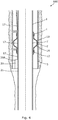
- Fig. 1 shows an annular barrier 10 in a well, expanded in an annulus 2 between a well tubular structure 1 and a wall 5 of another well tubular structure downhole for providing zone isolation between a first zone 101 and a second zone 102.
- the annular barrier 10 comprises a tubular metal part 7 for mounting as part of the well tubular structure 1, the tubular metal part having an axial extension L along the longitudinal extension of the well tubular structure.
- the tubular metal part 7 has a first expansion opening 3 through which pressurised fluid enters for expanding the annular barrier 10.
- the annular barrier 10 further comprises an expandable sleeve 8 surrounding the tubular metal part 7 and having an inner face 9 facing an outer face 4 of the tubular metal part, and an outer face 16 of the expandable sleeve 8 faces the wall of the well tubular structure 1.
- a first end 13 of the expandable sleeve 8 is connected to the tubular metal part 7 by a first connection part 11, and a second end 14 of the expandable sleeve is connected to the tubular metal part 7 by a second connection part 12.
- an annular space 15 is enclosed between the inner face 9 of the expandable sleeve 8 and the tubular metal part 7, which annular space 15 expands as the expandable sleeve 8 expands due to the pressurised fluid let into the annular space 15.
- the annular barrier 10 further comprises an electrical conductor 17 extending through the first connection part, from the first connection part 11 to the second connection part 12, through the annular space 15 and through the second connection part so that electricity can be conducted past the annular barrier 10 to an electrically demanding unit, e.g. a sensor 23 or a tool, further down the well without breaking the seal between the first zone 101 and the second zone 102 provided by the annular barrier.
- an electrically demanding unit e.g. a sensor 23 or a tool
- the annular barrier 10 is expanded between the well tubular structure 1 and the wall 5 of a borehole 6.
- the first connection part 11 and the second connection part 12 each have an electrical connection 24 connected to the electrical conductor 17, so that the electrical conductor is formed of a first part 35 extending in a first zone 101, a second part 36 extending inside the annular barrier 10, and a third part 37 extending in a second zone 102.
- the electrical conductor 17 can thus be formed of several parts forming one electrical conductor.
- the annular barrier 10 further comprises a tunnel 18 in the form of a tube arranged in the annular space 15 and extending between the first connection part 11 and the second connection part 12.
- the electrical conductor 17 runs in the tunnel 18, and a sealing means 19 is provided around the tunnel and around the electrical conductor 17 so that fluid from the first zone 101 is prevented from flowing into the second zone 102, and vice versa.
- the tunnel may be designed to collapse at a certain pressure when the annular barrier 10 expands, as the pressure inside the annular space 15 forces the tunnel to collapse and shrink around the electrical conductor.
- the tunnel inside the connection parts is not subject to this high expansion pressure so the connection therein is not jeopardised.
- the sealing means 19 may also be arranged in such a way that it seals directly around the electrical conductor 17 and is arranged in the connection parts 11, 12 and/or as part of the electrical connections 24.
- the annular barrier 10 further comprises a sensor 23 electrically connected with the electrical conductor 17 for taking measurements of e.g. pressure and temperature or the expansion ratio of the expandable sleeve 8 during expansion of the annular barrier. As can be seen, the electrical conductor 17 extends further past the sensor 23 to be electrically connected with other electrical devices further down the well.
- the annular barrier 10 comprises an expansion unit 41 arranged at the first expansion opening 3 so that the pressurised fluid enters the first expansion opening 3 and flows into the expansion unit 41 before being led into the annular space 15.
- the expansion unit 41 comprises a permanent closing mechanism which closes the fluid communication between the inside of the well tubular structure 1 and the annular space 15 in a first position after expansion of the expandable sleeve 8 and thus the annular barrier 10, and in a second position allows for fluid communication between the first zone 101 and the annular space 15 so that the pressure can be equalised therebetween, should the pressure in the second zone 102 increase during e.g. fracturing.
- the permanent closing mechanism is a two-way valve meaning a valve which in a first position provides fluid communication between the inside of the tubular metal part and the annular space within the annular barrier, and in a second position provides fluid communication between the annular space and the annulus between the borehole and the tubular metal part, and when in the first position, the fluid communication to the annulus is closed, and the second position, the fluid communication to the inside of the tubular metal part is closed.
- the permanent closing mechanism may even function as a three-way valve where fluid may also be led from the well tubular structure to the annulus.
- Fig. 4 shows a downhole system 100 comprising the well tubular structure 1 and a first annular barrier 10 being the annular barrier described above, where the tubular metal part is mounted as part of the well tubular structure.
- the electrical conductor 17 is led past the annular barrier 10, as described above, without breaking the barrier between the first zone 101 and the second zone 102 provided by the annular barrier 10. Furthermore, the electrical conductor 17 is electrically connected to a first electrical unit 20 arranged on an outer face 21 of the well tubular structure 1.
- the first electrical unit 20, 2A is an inductive coupler part 20A, meaning that a tool inside the well tubular structure 1 can be recharged by abutting the inner face of the well tubular structure opposite the inductive coupler part, and the tool can thus be charged without having to emerge all the way to surface or the well head, since power is conducted in the electrical conductor past one or more annular barrier(s) and further down the well. Furthermore, the well tubular structure 1 is intact, as the inductive coupler part 20A is arranged on the outside of the well tubular structure.
- the downhole system 100 of Fig. 5 further comprises a second electrical unit 20B arranged inside the first well tubular structure 1, 1A configured to abut an inner face 22 of the first well tubular structure and a second well tubular structure 1B arranged partly within the first well tubular structure 1A.
- the second electrical unit 20B is an inductive coupler part 20C, and electricity is thus conducted through the first well tubular structure 1A and further conducted in the electrical conductor 17 outside of the second well tubular structure 1B.
- the downhole system 100 further comprises a second annular barrier 10B having a tubular metal part 7 mounted as part of the second well tubular structure 1B and expanded between the first well tubular structure 1, 1A and the second well tubular structure 1, 1B.
- the electrical conductor 17, 17A extends through the first annular barrier through the connection parts to the first electrical unit, and a second electrical conductor 17, 17B extends from the second electrical unit 20B through a third annular barrier 10C to a third electrical unit 20D which can then be arranged several kilometres further down the well.
- the second electrical unit 20B is electrically connected to the third electrical unit 20D via the second electrical conductor 17B, and a tool inside the second well tubular structure 1B can thus be electrically powered several kilometres down the well by abutting the inner face of the second well tubular structure opposite the inductive coupler part of the second electrical unit 20B.
- the electrical conductor runs through several annular barriers before reaching the fourth electrical unit 20E and may run through even further electrical units and annular barriers, as shown in Figs. 6 and 8 .
- the downhole system 100 shown in Fig. 6 comprises a lateral tubular structure 31 extending from a window opening in the second well tubular structure 1B.
- the downhole system 100 further comprises a tool 50 arranged in the lateral tubular structure 31 of the well tubular structure 1, and the tool comprises an inductive tool coupler part 51 configured to be electrically connected with the inductive coupler part when the tool abuts the inner face of the lateral tubular structure 31, as shown.
- the downhole system 100 further comprises a sensor 23 arranged outside one of the second well tubular structures for measuring e.g. temperature and/or pressure.
- the downhole system 100 has a sleeve 55 movable by the sleeve control 57 for uncovering an aperture 54 or aligning a sleeve opening 58 with the aperture 54 allowing fluid to flow therethrough.
- the sleeve control 57 further comprises an inductive tool coupler part 51 for receiving control signals from surface to open, choke or close fluid communication through the aperture.
- the sleeve control 57 is thus permanently installed in the production casing 1B, ready to move the sleeve from one position to another in order to choke, open or close fluid communication from the reservoir.
- the sleeve control 57 has its own power supply and can operate on its own when receiving a control signal during production of fluid from the reservoir, without the well being intervened by commonly used intervention tools.
- the inductive tool coupler part 51 of the sleeve control 57 of the tool 50 is arranged in the fixation unit 61 abutting the restriction 39 and the inner face of the casing 1B.
- the first electrical unit 20A arranged on an outer face of the first well tubular structure 1A and a second electrical unit 20B arranged on an inner face of the first well tubular structure 1A communicate via the casing/well tubular structure 1A.
- the second electrical unit 20B and the third electrical unit 20D arranged further down the well communicate via the electrical conductor 17 running through an annular barrier 10.
- the inductive tool coupler part 51 and the third electrical unit 20D are electrically connected via electromagnetic induction and transfer signals and electrical power between them through the well tubular structure 1B.
- the sleeve control 57 comprises a first part 68 having members 69 engaging the profile 56, and a second part 70 having the fixation unit 61 fixating the sleeve control 57 in the casing.
- the sleeve control 57 comprises an actuator 72 for moving the first part 68 in relation to the second part 60, and a power supply 64, such as a battery, supplying power to the actuator.
- the battery may be charged through the well tubular structure 1B by the third electrical unit 20D.
- the power supply may also be recharged by the inductive tool coupler part 51 converting mud pulses, an electrical field or acoustic waves into electrical energy.
- the inductive tool coupler part 51 may also comprise a propeller 21A in connection with a generator 22A for recharging the power supply by converting rotational energy generated by fluid in the production casing 2 into electrical energy, as shown in Fig. 7 .
- the downhole system 100 comprises completion components 55 where a first part 5a of the completion component is a member 69 engaging the profile 56 of a second part 5b of the completion component.
- the first part 5a of the completion component is arranged at the component control 57.
- the inductive tool coupler part 51 of the component control 57 is arranged in the fixation unit 61 abutting the restriction 39 and the inner face of the casing/well tubular structure 1B.
- the first electrical unit 20A arranged on an outer face of the intermediate casing and a second electrical unit 20B arranged on an inner face of the intermediate casing communicate via the well tubular structure 1A.
- the first electrical unit 20A is electrically connected to surface via wiring 17 extending through the main barrier 65.
- the first electrical unit 20A and the second electrical unit 20B are electrically connected via electromagnetic induction and transfer signals and electrical power between them through the intermediate casing 1A.
- the third electrical unit 20D is connected with the second electrical unit 20B by means of wiring or an electrical conductor, such as a cable, a cord or a wire running through an annular barrier 10.
- the third electrical unit 20D is arranged on the outer face of the production casing 1B further down the well but above the lateral tubular structure 81.
- a fourth electrical unit 20E being a fourth communication unit is arranged opposite the inductive tool coupler part 51 of the component control 57.
- the third communication unit and fourth communication unit/electrical units are electrically connected via wiring 17.
- the fourth communication unit and the inductive tool coupler part 51 transfer signals and electrical power between them via electromagnetic induction through the production casing 1B.
- the third electrical unit 20D is furthermore electrically connected with a fifth electrical unit 20F arranged outside the main casing which is the production casing 1B.
- the fifth electrical unit 20F is arranged opposite the inductive tool coupler part 51 of another component control 57 in the main casing and transfers signals and power by means of electromagnetic induction through the production casing 1B.
- Both the wiring 17 between the second electrical unit 20B and the third electrical unit 20D and between the third electrical unit 20D and the fourth electrical unit 20E runs past an annular barrier 10.
- the wiring 17 extends in through one of the connection parts 11, 12 connecting the expandable sleeve 8 with the tubular metal part 7, and past the space 15 and through the other connection part further down the well.
- the wiring 17 of Fig. 8 between the third electrical unit 20D and the fifth electrical unit 20F extends past the lateral tubular structure 81 on the outside of the main casing 1B and through the annular barrier 10 arranged further down the main casing.
- All the communication units each comprise an inductive coupler for transferring power from one communication unit to another through the casing by means of electromagnetic induction.
- the casing may have non-magnetic sections opposite the communication units to optimise the transfer by electromagnetic induction.
- the tool may be a stroking tool which is a tool providing an axial force, e.g. for opening or closing a sliding sleeve.
- the stroking tool comprises an electrical motor for driving a pump.
- the pump pumps fluid into a piston housing to move a piston acting therein.
- the piston is arranged on the stroker shaft.
- the pump may pump fluid into the piston housing on one side and simultaneously suck fluid out on the other side of the piston.
- the tool may also be a driving unit/propulsion unit, such as a downhole tractor.
- fluid or well fluid any kind of fluid that may be present in oil or gas wells downhole, such as natural gas, oil, oil mud, crude oil, water, etc.
- gas is meant any kind of gas composition present in a well, completion, or open hole
- oil is meant any kind of oil composition, such as crude oil, an oil-containing fluid, etc.
- Gas, oil, and water fluids may thus all comprise other elements or substances than gas, oil, and/or water, respectively.
- a well tubular structure is meant any kind of pipe, tubing, tubular, liner, string etc. used downhole in relation to oil or natural gas production.
- a downhole tractor can be used to push the tool all the way into position in the well.
- the downhole tractor may have projectable arms having wheels, wherein the wheels contact the inner surface of the well tubular structure for propelling the tractor and the tool forward in the well tubular structure.
- a downhole tractor is any kind of driving tool capable of pushing or pulling tools in a well downhole, such as a Well Tractor®.
Landscapes
- Engineering & Computer Science (AREA)
- Geology (AREA)
- Life Sciences & Earth Sciences (AREA)
- Mining & Mineral Resources (AREA)
- Physics & Mathematics (AREA)
- General Life Sciences & Earth Sciences (AREA)
- Fluid Mechanics (AREA)
- Environmental & Geological Engineering (AREA)
- Geochemistry & Mineralogy (AREA)
- Mechanical Engineering (AREA)
- Geophysics (AREA)
- Remote Sensing (AREA)
- Electromagnetism (AREA)
- Laying Of Electric Cables Or Lines Outside (AREA)
- Arrangements For Transmission Of Measured Signals (AREA)
- Earth Drilling (AREA)
- Near-Field Transmission Systems (AREA)
Claims (12)
- Bohrlochsystem zur Komplettierung einer Bohrlochanlage mit einer kabellosen Energieversorgung und Kommunikation unten im Bohrloch, Folgendes umfassend:- eine erste Bohrloch-Röhrenstruktur (1A),- eine zweite Bohrloch-Röhrenstruktur (1B), die teilweise innerhalb der ersten Bohrloch-Röhrenstruktur angeordnet ist,- eine erste elektrische Einheit (20), die einen ersten Teil zur induktiven Kopplung (20A) umfasst und die auf einer Außenseite (21) der ersten Bohrloch-Röhrenstruktur angeordnet und mit einem elektrischen Leiter elektrisch verbunden ist,- eine ringförmige Sperre (10), die dafür vorgesehen ist, in einem Ring (2) zwischen der ersten Bohrloch-Röhrenstruktur (1A) und einer Wand (5) eines Bohrlochs (6) oder einer weiteren Bohrloch-Röhrenstruktur unten im Bohrloch expandiert zu werden, um eine Zonenabsperrung zwischen einer ersten Zone (101), die einen ersten Druck (P1) hat, und einer zweiten Zone (102) bereitzustellen, wobei die ringförmige Sperre Folgendes umfasst:- ein röhrenförmiges Metallteil (7), das dafür vorgesehen ist, als Teil der ersten Bohrloch-Röhrenstruktur montiert zu werden, wobei das röhrenförmige Metallteil eine erste Expansionsöffnung (3), eine axiale Ausdehnung (L) und eine Außenseite (4) hat,- eine expandierbare Hülse (8), die das röhrenförmige Metallteil umgibt und die eine Innenseite (9) hat, die dem röhrenförmigen Metallteil zugewandt ist, sowie eine Außenseite (16), die der Wand des Bohrlochs zugewandt ist,- ein erstes Verbindungsteil (11) und ein zweites Verbindungsteil (12), die dafür eingerichtet sind, ein erstes Ende (13) bzw. ein zweites Ende (14) der expandierbaren Hülse mit dem röhrenförmigen Metallteil zu verbinden, und- einen ringförmigen Raum (15) zwischen der Innenseite der expandierbaren Hülse und dem röhrenförmigen Metallteil,
wobei die ringförmige Sperre außerdem den elektrischen Leiter (17) umfasst, der sich auf der Außenseite des röhrenförmigen Metallteils und innerhalb der expandierbaren Hülse vom ersten Verbindungsteil zum zweiten Verbindungsteil erstreckt, und- eine zweite elektrische Einheit (20B), die einen zweiten Teil zur induktiven Kopplung (20C) umfasst und die innerhalb der ersten Bohrloch-Röhrenstruktur (1A) angeordnet ist und die außerhalb der zweiten Bohrloch-Röhrenstruktur (1B) angeordnet ist, und die dafür eingerichtet ist, an eine Innenseite (22) der ersten Bohrloch-Röhrenstruktur (1A) anzugrenzen, wobei die erste elektrische Einheit Energie und/oder Kommunikation zur zweiten elektrischen Einheit (20B) überträgt. - Bohrlochsystem nach Anspruch 1, wobei eine Außenseite der zweiten Bohrloch-Röhrenstruktur (1B) der Wand des Bohrlochs zugewandt ist.
- Bohrlochsystem nach Anspruch 1 oder 2, wobei die zweite elektrische Einheit mit einer dritten elektrischen Einheit (20D) über einen zweiten elektrischen Leiter (17, 17B) elektrisch verbunden ist.
- Bohrlochsystem nach einem der Ansprüche 1 bis 3, das außerdem eine zweite ringförmige Sperre (10B) umfasst, durch die hindurch sich der zweite elektrische Leiter erstreckt.
- Bohrlochsystem nach Anspruch 4, wobei das röhrenförmige Metallteil der zweiten ringförmigen Sperre ein Teil der zweiten Bohrloch-Röhrenstruktur ist.
- Bohrlochsystem nach einem der Ansprüche 1 bis 5, das außerdem eine Neben-Röhrenstruktur (31) umfasst, die mit einer der Bohrloch-Röhrenstrukturen verbunden ist, und wobei eine dritte elektrische Einheit (20D) außerhalb der Neben-Röhrenstruktur eingerichtet ist.
- Bohrlochsystem nach einem der Ansprüche 1 bis 6, das außerdem ein Werkzeug (50) umfasst, das in der zweiten Bohrloch-Röhrenstruktur angeordnet ist, wobei das Werkzeug einen Teil zur induktiven Werkzeugkopplung (51) umfasst, der dafür eingerichtet ist, mit dem Teil zur induktiven Kopplung elektrisch verbunden zu sein.
- Bohrlochsystem nach einem der Ansprüche 1 bis 7, das außerdem einen Sensor (23) umfasst, der außerhalb einer der zweiten Bohrloch-Röhrenstrukturen angeordnet ist.
- Bohrlochsystem nach einem der Ansprüche 1 bis 8, wobei die ringförmige Sperre einen Tunnel (18) umfasst, der in dem Raum zwischen dem ersten Verbindungsteil und dem zweiten Verbindungsteil eingerichtet ist, wobei sich in diesem Tunnel der elektrische Leiter erstreckt.
- Bohrlochsystem nach einem der Ansprüche 1 bis 9, wobei die Verbindungsteile der ringförmigen Sperren, die die expandierbare Hülse mit dem röhrenförmigen Metallteil verbinden, als röhrenförmige Verbindungsteile ausgebildet sind, die eine Bohrung haben, wobei durch diese Bohrung der elektrische Leiter hindurchläuft.
- Bohrlochsystem nach einem der Ansprüche 1 bis 10, wobei die erste elektrische Einheit und die zweite elektrische Einheit drahtlos durch die erste Bohrloch-Röhrenstruktur hindurch kommunizieren.
- Bohrlochsystem nach einem der Ansprüche 1 bis 11, wobei von dem ersten Verbindungsteil und dem zweiten Verbindungsteil jedes einen elektrischen Anschluss (24) hat, der dafür eingerichtet ist, mit dem elektrischen Leiter zu verbinden.
Applications Claiming Priority (3)
| Application Number | Priority Date | Filing Date | Title |
|---|---|---|---|
| EP15195919 | 2015-11-23 | ||
| EP16150086.3A EP3187682A1 (de) | 2016-01-04 | 2016-01-04 | Mit einem elektrischen leiter augestattete ringförmige bohrlochabsperrungsanordnung |
| PCT/EP2016/078422 WO2017089343A1 (en) | 2015-11-23 | 2016-11-22 | Annular barrier completion with inductive system |
Publications (2)
| Publication Number | Publication Date |
|---|---|
| EP3380698A1 EP3380698A1 (de) | 2018-10-03 |
| EP3380698B1 true EP3380698B1 (de) | 2020-08-26 |
Family
ID=57354389
Family Applications (1)
| Application Number | Title | Priority Date | Filing Date |
|---|---|---|---|
| EP16798530.8A Active EP3380698B1 (de) | 2015-11-23 | 2016-11-22 | Mit einem elektrischen leiter augestattete ringförmige bohrlochabsperrungsanordnung |
Country Status (12)
| Country | Link |
|---|---|
| US (1) | US10100599B2 (de) |
| EP (1) | EP3380698B1 (de) |
| CN (1) | CN108350730A (de) |
| AU (1) | AU2016358614B2 (de) |
| BR (1) | BR112018009309B1 (de) |
| CA (1) | CA3004803A1 (de) |
| DK (1) | DK3380698T3 (de) |
| MX (1) | MX2018005844A (de) |
| MY (1) | MY191715A (de) |
| RU (1) | RU2738918C2 (de) |
| SA (1) | SA518391529B1 (de) |
| WO (1) | WO2017089343A1 (de) |
Families Citing this family (8)
| Publication number | Priority date | Publication date | Assignee | Title |
|---|---|---|---|---|
| BR112016028863B1 (pt) | 2014-07-10 | 2021-11-23 | Halliburton Energy Services, Inc | Encaixe de junção, sistema de poço, e, método para completar um poço. |
| MX386266B (es) * | 2014-09-17 | 2025-03-11 | Halliburton Energy Services Inc | Deflector de terminacion para la terminacion inteligente de un pozo. |
| WO2018178607A1 (en) * | 2017-03-31 | 2018-10-04 | Metrol Technology Ltd | Monitoring well installations |
| US10696365B2 (en) | 2018-04-24 | 2020-06-30 | Saudi Arabian Oil Company | Oil field well downhole drone |
| US11286737B2 (en) | 2018-12-28 | 2022-03-29 | Halliburton Energy Services, Inc. | Fluid-free hydraulic connector |
| EP4015763A1 (de) * | 2020-12-18 | 2022-06-22 | Welltec Oilfield Solutions AG | Bohrlochabschlusssystem |
| WO2023283094A1 (en) | 2021-07-07 | 2023-01-12 | Schlumberger Technology Corporation | System and methodology for providing bypass through an expandable metal packer |
| US12497854B2 (en) * | 2023-05-26 | 2025-12-16 | Welltec Manufacturing Center Completions ApS | Completion system for CCS monitoring |
Family Cites Families (10)
| Publication number | Priority date | Publication date | Assignee | Title |
|---|---|---|---|---|
| US3899631A (en) * | 1974-04-11 | 1975-08-12 | Lynes Inc | Inflatable sealing element having electrical conductors extending therethrough |
| RU56939U1 (ru) * | 2006-01-10 | 2006-09-27 | Олег Марсович Гарипов | Пакер гарипова |
| RU92689U1 (ru) * | 2009-11-09 | 2010-03-27 | Общество с ограниченной ответственностью "Научно-производственная фирма Завод "Измерон" | Пакер с кабельным вводом |
| EP2565369A1 (de) * | 2011-08-31 | 2013-03-06 | Welltec A/S | Ringförmige Absperrung mit Ausgleichsvorrichtung |
| US20130075087A1 (en) * | 2011-09-23 | 2013-03-28 | Schlumberger Technology Corporation | Module For Use With Completion Equipment |
| EP2599955A1 (de) * | 2011-11-30 | 2013-06-05 | Welltec A/S | Druckintegrität-Prüfsystem |
| EP2642066A1 (de) | 2012-03-23 | 2013-09-25 | Welltec A/S | Bohrlocherkennungssystem |
| US10036234B2 (en) * | 2012-06-08 | 2018-07-31 | Schlumberger Technology Corporation | Lateral wellbore completion apparatus and method |
| BR112016007124B1 (pt) * | 2013-10-03 | 2021-12-07 | Schlumberger Technology B.V. | Sistema para detectar fundo de poço, método para detectar um furo, e método |
| RU2540369C2 (ru) * | 2014-01-21 | 2015-02-10 | Олег Сергеевич Николаев | Пакер с кабельным вводом |
-
2016
- 2016-11-22 WO PCT/EP2016/078422 patent/WO2017089343A1/en not_active Ceased
- 2016-11-22 MX MX2018005844A patent/MX2018005844A/es unknown
- 2016-11-22 RU RU2018120759A patent/RU2738918C2/ru active
- 2016-11-22 BR BR112018009309-2A patent/BR112018009309B1/pt active IP Right Grant
- 2016-11-22 US US15/358,940 patent/US10100599B2/en active Active
- 2016-11-22 AU AU2016358614A patent/AU2016358614B2/en active Active
- 2016-11-22 DK DK16798530.8T patent/DK3380698T3/da active
- 2016-11-22 MY MYPI2018000534A patent/MY191715A/en unknown
- 2016-11-22 CN CN201680065191.7A patent/CN108350730A/zh active Pending
- 2016-11-22 CA CA3004803A patent/CA3004803A1/en not_active Abandoned
- 2016-11-22 EP EP16798530.8A patent/EP3380698B1/de active Active
-
2018
- 2018-05-07 SA SA518391529A patent/SA518391529B1/ar unknown
Non-Patent Citations (1)
| Title |
|---|
| None * |
Also Published As
| Publication number | Publication date |
|---|---|
| RU2018120759A3 (de) | 2020-04-17 |
| MX2018005844A (es) | 2018-08-01 |
| SA518391529B1 (ar) | 2022-02-15 |
| RU2018120759A (ru) | 2019-12-25 |
| EP3380698A1 (de) | 2018-10-03 |
| US20170145777A1 (en) | 2017-05-25 |
| RU2738918C2 (ru) | 2020-12-18 |
| BR112018009309A8 (pt) | 2019-02-26 |
| BR112018009309B1 (pt) | 2022-10-18 |
| WO2017089343A1 (en) | 2017-06-01 |
| BR112018009309A2 (pt) | 2018-11-06 |
| CA3004803A1 (en) | 2017-06-01 |
| MY191715A (en) | 2022-07-09 |
| CN108350730A (zh) | 2018-07-31 |
| AU2016358614B2 (en) | 2019-05-16 |
| US10100599B2 (en) | 2018-10-16 |
| AU2016358614A1 (en) | 2018-06-28 |
| DK3380698T3 (da) | 2020-11-30 |
Similar Documents
| Publication | Publication Date | Title |
|---|---|---|
| EP3380698B1 (de) | Mit einem elektrischen leiter augestattete ringförmige bohrlochabsperrungsanordnung | |
| US7510017B2 (en) | Sealing and communicating in wells | |
| US9166352B2 (en) | Downhole electrical coupler for electrically operated wellbore pumps and the like | |
| US9175560B2 (en) | Providing coupler portions along a structure | |
| US20130075087A1 (en) | Module For Use With Completion Equipment | |
| RU2587205C2 (ru) | Поршневая тянущая система, используемая в подземных скважинах | |
| EP3265644B1 (de) | Bohrlochsenkwerkzeug | |
| EP3187682A1 (de) | Mit einem elektrischen leiter augestattete ringförmige bohrlochabsperrungsanordnung | |
| US20150226053A1 (en) | Reactive multilayer foil usage in wired pipe systems | |
| US9644433B2 (en) | Electronic frame having conductive and bypass paths for electrical inputs for use with coupled conduit segments | |
| US12338689B2 (en) | Downhole wet-mate systems and methods using wet-mate deployment carrier | |
| AU2016423067B2 (en) | Travel joint | |
| US10597975B2 (en) | Downhole completion system | |
| EP3112581A1 (de) | Bohrlochsenkwerkzeug | |
| EP3070258A1 (de) | Bohrlochsenkwerkzeug |
Legal Events
| Date | Code | Title | Description |
|---|---|---|---|
| STAA | Information on the status of an ep patent application or granted ep patent |
Free format text: STATUS: UNKNOWN |
|
| STAA | Information on the status of an ep patent application or granted ep patent |
Free format text: STATUS: THE INTERNATIONAL PUBLICATION HAS BEEN MADE |
|
| PUAI | Public reference made under article 153(3) epc to a published international application that has entered the european phase |
Free format text: ORIGINAL CODE: 0009012 |
|
| STAA | Information on the status of an ep patent application or granted ep patent |
Free format text: STATUS: REQUEST FOR EXAMINATION WAS MADE |
|
| 17P | Request for examination filed |
Effective date: 20180601 |
|
| AK | Designated contracting states |
Kind code of ref document: A1 Designated state(s): AL AT BE BG CH CY CZ DE DK EE ES FI FR GB GR HR HU IE IS IT LI LT LU LV MC MK MT NL NO PL PT RO RS SE SI SK SM TR |
|
| AX | Request for extension of the european patent |
Extension state: BA ME |
|
| RAP1 | Party data changed (applicant data changed or rights of an application transferred) |
Owner name: WELLTEC OILFIELD SOLUTIONS AG |
|
| DAV | Request for validation of the european patent (deleted) | ||
| DAX | Request for extension of the european patent (deleted) | ||
| STAA | Information on the status of an ep patent application or granted ep patent |
Free format text: STATUS: EXAMINATION IS IN PROGRESS |
|
| 17Q | First examination report despatched |
Effective date: 20190321 |
|
| GRAP | Despatch of communication of intention to grant a patent |
Free format text: ORIGINAL CODE: EPIDOSNIGR1 |
|
| STAA | Information on the status of an ep patent application or granted ep patent |
Free format text: STATUS: GRANT OF PATENT IS INTENDED |
|
| INTG | Intention to grant announced |
Effective date: 20191129 |
|
| RIN1 | Information on inventor provided before grant (corrected) |
Inventor name: VASQUES, RICARDO REVES Inventor name: HAZEL, PAUL |
|
| GRAJ | Information related to disapproval of communication of intention to grant by the applicant or resumption of examination proceedings by the epo deleted |
Free format text: ORIGINAL CODE: EPIDOSDIGR1 |
|
| STAA | Information on the status of an ep patent application or granted ep patent |
Free format text: STATUS: EXAMINATION IS IN PROGRESS |
|
| GRAS | Grant fee paid |
Free format text: ORIGINAL CODE: EPIDOSNIGR3 |
|
| STAA | Information on the status of an ep patent application or granted ep patent |
Free format text: STATUS: GRANT OF PATENT IS INTENDED |
|
| GRAP | Despatch of communication of intention to grant a patent |
Free format text: ORIGINAL CODE: EPIDOSNIGR1 |
|
| INTG | Intention to grant announced |
Effective date: 20200326 |
|
| RAP1 | Party data changed (applicant data changed or rights of an application transferred) |
Owner name: WELLTEC OILFIELD SOLUTIONS AG |
|
| GRAA | (expected) grant |
Free format text: ORIGINAL CODE: 0009210 |
|
| STAA | Information on the status of an ep patent application or granted ep patent |
Free format text: STATUS: THE PATENT HAS BEEN GRANTED |
|
| AK | Designated contracting states |
Kind code of ref document: B1 Designated state(s): AL AT BE BG CH CY CZ DE DK EE ES FI FR GB GR HR HU IE IS IT LI LT LU LV MC MK MT NL NO PL PT RO RS SE SI SK SM TR |
|
| REG | Reference to a national code |
Ref country code: GB Ref legal event code: FG4D |
|
| REG | Reference to a national code |
Ref country code: CH Ref legal event code: EP |
|
| REG | Reference to a national code |
Ref country code: AT Ref legal event code: REF Ref document number: 1306544 Country of ref document: AT Kind code of ref document: T Effective date: 20200915 |
|
| REG | Reference to a national code |
Ref country code: IE Ref legal event code: FG4D |
|
| REG | Reference to a national code |
Ref country code: DE Ref legal event code: R096 Ref document number: 602016042823 Country of ref document: DE |
|
| REG | Reference to a national code |
Ref country code: NL Ref legal event code: FP |
|
| REG | Reference to a national code |
Ref country code: DK Ref legal event code: T3 Effective date: 20201126 |
|
| REG | Reference to a national code |
Ref country code: NO Ref legal event code: T2 Effective date: 20200826 |
|
| PGFP | Annual fee paid to national office [announced via postgrant information from national office to epo] |
Ref country code: NL Payment date: 20201125 Year of fee payment: 5 |
|
| REG | Reference to a national code |
Ref country code: LT Ref legal event code: MG4D |
|
| PG25 | Lapsed in a contracting state [announced via postgrant information from national office to epo] |
Ref country code: PT Free format text: LAPSE BECAUSE OF FAILURE TO SUBMIT A TRANSLATION OF THE DESCRIPTION OR TO PAY THE FEE WITHIN THE PRESCRIBED TIME-LIMIT Effective date: 20201228 Ref country code: FI Free format text: LAPSE BECAUSE OF FAILURE TO SUBMIT A TRANSLATION OF THE DESCRIPTION OR TO PAY THE FEE WITHIN THE PRESCRIBED TIME-LIMIT Effective date: 20200826 Ref country code: SE Free format text: LAPSE BECAUSE OF FAILURE TO SUBMIT A TRANSLATION OF THE DESCRIPTION OR TO PAY THE FEE WITHIN THE PRESCRIBED TIME-LIMIT Effective date: 20200826 Ref country code: HR Free format text: LAPSE BECAUSE OF FAILURE TO SUBMIT A TRANSLATION OF THE DESCRIPTION OR TO PAY THE FEE WITHIN THE PRESCRIBED TIME-LIMIT Effective date: 20200826 Ref country code: LT Free format text: LAPSE BECAUSE OF FAILURE TO SUBMIT A TRANSLATION OF THE DESCRIPTION OR TO PAY THE FEE WITHIN THE PRESCRIBED TIME-LIMIT Effective date: 20200826 Ref country code: GR Free format text: LAPSE BECAUSE OF FAILURE TO SUBMIT A TRANSLATION OF THE DESCRIPTION OR TO PAY THE FEE WITHIN THE PRESCRIBED TIME-LIMIT Effective date: 20201127 Ref country code: BG Free format text: LAPSE BECAUSE OF FAILURE TO SUBMIT A TRANSLATION OF THE DESCRIPTION OR TO PAY THE FEE WITHIN THE PRESCRIBED TIME-LIMIT Effective date: 20201126 |
|
| REG | Reference to a national code |
Ref country code: AT Ref legal event code: MK05 Ref document number: 1306544 Country of ref document: AT Kind code of ref document: T Effective date: 20200826 |
|
| PG25 | Lapsed in a contracting state [announced via postgrant information from national office to epo] |
Ref country code: LV Free format text: LAPSE BECAUSE OF FAILURE TO SUBMIT A TRANSLATION OF THE DESCRIPTION OR TO PAY THE FEE WITHIN THE PRESCRIBED TIME-LIMIT Effective date: 20200826 Ref country code: PL Free format text: LAPSE BECAUSE OF FAILURE TO SUBMIT A TRANSLATION OF THE DESCRIPTION OR TO PAY THE FEE WITHIN THE PRESCRIBED TIME-LIMIT Effective date: 20200826 Ref country code: RS Free format text: LAPSE BECAUSE OF FAILURE TO SUBMIT A TRANSLATION OF THE DESCRIPTION OR TO PAY THE FEE WITHIN THE PRESCRIBED TIME-LIMIT Effective date: 20200826 Ref country code: IS Free format text: LAPSE BECAUSE OF FAILURE TO SUBMIT A TRANSLATION OF THE DESCRIPTION OR TO PAY THE FEE WITHIN THE PRESCRIBED TIME-LIMIT Effective date: 20201226 |
|
| PG25 | Lapsed in a contracting state [announced via postgrant information from national office to epo] |
Ref country code: SM Free format text: LAPSE BECAUSE OF FAILURE TO SUBMIT A TRANSLATION OF THE DESCRIPTION OR TO PAY THE FEE WITHIN THE PRESCRIBED TIME-LIMIT Effective date: 20200826 Ref country code: EE Free format text: LAPSE BECAUSE OF FAILURE TO SUBMIT A TRANSLATION OF THE DESCRIPTION OR TO PAY THE FEE WITHIN THE PRESCRIBED TIME-LIMIT Effective date: 20200826 Ref country code: CZ Free format text: LAPSE BECAUSE OF FAILURE TO SUBMIT A TRANSLATION OF THE DESCRIPTION OR TO PAY THE FEE WITHIN THE PRESCRIBED TIME-LIMIT Effective date: 20200826 Ref country code: RO Free format text: LAPSE BECAUSE OF FAILURE TO SUBMIT A TRANSLATION OF THE DESCRIPTION OR TO PAY THE FEE WITHIN THE PRESCRIBED TIME-LIMIT Effective date: 20200826 |
|
| REG | Reference to a national code |
Ref country code: DE Ref legal event code: R097 Ref document number: 602016042823 Country of ref document: DE |
|
| PG25 | Lapsed in a contracting state [announced via postgrant information from national office to epo] |
Ref country code: AL Free format text: LAPSE BECAUSE OF FAILURE TO SUBMIT A TRANSLATION OF THE DESCRIPTION OR TO PAY THE FEE WITHIN THE PRESCRIBED TIME-LIMIT Effective date: 20200826 Ref country code: AT Free format text: LAPSE BECAUSE OF FAILURE TO SUBMIT A TRANSLATION OF THE DESCRIPTION OR TO PAY THE FEE WITHIN THE PRESCRIBED TIME-LIMIT Effective date: 20200826 Ref country code: ES Free format text: LAPSE BECAUSE OF FAILURE TO SUBMIT A TRANSLATION OF THE DESCRIPTION OR TO PAY THE FEE WITHIN THE PRESCRIBED TIME-LIMIT Effective date: 20200826 |
|
| REG | Reference to a national code |
Ref country code: DE Ref legal event code: R119 Ref document number: 602016042823 Country of ref document: DE |
|
| PG25 | Lapsed in a contracting state [announced via postgrant information from national office to epo] |
Ref country code: SK Free format text: LAPSE BECAUSE OF FAILURE TO SUBMIT A TRANSLATION OF THE DESCRIPTION OR TO PAY THE FEE WITHIN THE PRESCRIBED TIME-LIMIT Effective date: 20200826 Ref country code: MC Free format text: LAPSE BECAUSE OF FAILURE TO SUBMIT A TRANSLATION OF THE DESCRIPTION OR TO PAY THE FEE WITHIN THE PRESCRIBED TIME-LIMIT Effective date: 20200826 |
|
| REG | Reference to a national code |
Ref country code: CH Ref legal event code: PL |
|
| PLBE | No opposition filed within time limit |
Free format text: ORIGINAL CODE: 0009261 |
|
| STAA | Information on the status of an ep patent application or granted ep patent |
Free format text: STATUS: NO OPPOSITION FILED WITHIN TIME LIMIT |
|
| PG25 | Lapsed in a contracting state [announced via postgrant information from national office to epo] |
Ref country code: IT Free format text: LAPSE BECAUSE OF FAILURE TO SUBMIT A TRANSLATION OF THE DESCRIPTION OR TO PAY THE FEE WITHIN THE PRESCRIBED TIME-LIMIT Effective date: 20200826 Ref country code: LU Free format text: LAPSE BECAUSE OF NON-PAYMENT OF DUE FEES Effective date: 20201122 |
|
| 26N | No opposition filed |
Effective date: 20210527 |
|
| REG | Reference to a national code |
Ref country code: BE Ref legal event code: MM Effective date: 20201130 |
|
| PG25 | Lapsed in a contracting state [announced via postgrant information from national office to epo] |
Ref country code: CH Free format text: LAPSE BECAUSE OF NON-PAYMENT OF DUE FEES Effective date: 20201130 Ref country code: LI Free format text: LAPSE BECAUSE OF NON-PAYMENT OF DUE FEES Effective date: 20201130 Ref country code: SI Free format text: LAPSE BECAUSE OF FAILURE TO SUBMIT A TRANSLATION OF THE DESCRIPTION OR TO PAY THE FEE WITHIN THE PRESCRIBED TIME-LIMIT Effective date: 20200826 |
|
| PG25 | Lapsed in a contracting state [announced via postgrant information from national office to epo] |
Ref country code: IE Free format text: LAPSE BECAUSE OF NON-PAYMENT OF DUE FEES Effective date: 20201122 |
|
| PG25 | Lapsed in a contracting state [announced via postgrant information from national office to epo] |
Ref country code: DE Free format text: LAPSE BECAUSE OF NON-PAYMENT OF DUE FEES Effective date: 20210601 |
|
| PG25 | Lapsed in a contracting state [announced via postgrant information from national office to epo] |
Ref country code: TR Free format text: LAPSE BECAUSE OF FAILURE TO SUBMIT A TRANSLATION OF THE DESCRIPTION OR TO PAY THE FEE WITHIN THE PRESCRIBED TIME-LIMIT Effective date: 20200826 Ref country code: MT Free format text: LAPSE BECAUSE OF FAILURE TO SUBMIT A TRANSLATION OF THE DESCRIPTION OR TO PAY THE FEE WITHIN THE PRESCRIBED TIME-LIMIT Effective date: 20200826 Ref country code: CY Free format text: LAPSE BECAUSE OF FAILURE TO SUBMIT A TRANSLATION OF THE DESCRIPTION OR TO PAY THE FEE WITHIN THE PRESCRIBED TIME-LIMIT Effective date: 20200826 |
|
| PG25 | Lapsed in a contracting state [announced via postgrant information from national office to epo] |
Ref country code: MK Free format text: LAPSE BECAUSE OF FAILURE TO SUBMIT A TRANSLATION OF THE DESCRIPTION OR TO PAY THE FEE WITHIN THE PRESCRIBED TIME-LIMIT Effective date: 20200826 |
|
| REG | Reference to a national code |
Ref country code: NL Ref legal event code: MM Effective date: 20211201 |
|
| PG25 | Lapsed in a contracting state [announced via postgrant information from national office to epo] |
Ref country code: BE Free format text: LAPSE BECAUSE OF NON-PAYMENT OF DUE FEES Effective date: 20201130 |
|
| PG25 | Lapsed in a contracting state [announced via postgrant information from national office to epo] |
Ref country code: NL Free format text: LAPSE BECAUSE OF NON-PAYMENT OF DUE FEES Effective date: 20211201 |
|
| P01 | Opt-out of the competence of the unified patent court (upc) registered |
Effective date: 20230523 |
|
| REG | Reference to a national code |
Ref country code: GB Ref legal event code: 732E Free format text: REGISTERED BETWEEN 20241017 AND 20241023 |
|
| PGFP | Annual fee paid to national office [announced via postgrant information from national office to epo] |
Ref country code: GB Payment date: 20251117 Year of fee payment: 10 |
|
| PGFP | Annual fee paid to national office [announced via postgrant information from national office to epo] |
Ref country code: NO Payment date: 20251120 Year of fee payment: 10 |
|
| PGFP | Annual fee paid to national office [announced via postgrant information from national office to epo] |
Ref country code: DK Payment date: 20251120 Year of fee payment: 10 |
|
| PGFP | Annual fee paid to national office [announced via postgrant information from national office to epo] |
Ref country code: FR Payment date: 20251117 Year of fee payment: 10 |