EP3226572A1 - Appareil et procédé pour émettre et recevoir un signal de diffusion - Google Patents
Appareil et procédé pour émettre et recevoir un signal de diffusion Download PDFInfo
- Publication number
- EP3226572A1 EP3226572A1 EP15863663.9A EP15863663A EP3226572A1 EP 3226572 A1 EP3226572 A1 EP 3226572A1 EP 15863663 A EP15863663 A EP 15863663A EP 3226572 A1 EP3226572 A1 EP 3226572A1
- Authority
- EP
- European Patent Office
- Prior art keywords
- bits
- signaling information
- data
- ldpc
- frame
- Prior art date
- Legal status (The legal status is an assumption and is not a legal conclusion. Google has not performed a legal analysis and makes no representation as to the accuracy of the status listed.)
- Withdrawn
Links
Images


Classifications
-
- H—ELECTRICITY
- H04—ELECTRIC COMMUNICATION TECHNIQUE
- H04L—TRANSMISSION OF DIGITAL INFORMATION, e.g. TELEGRAPHIC COMMUNICATION
- H04L1/00—Arrangements for detecting or preventing errors in the information received
- H04L1/004—Arrangements for detecting or preventing errors in the information received by using forward error control
- H04L1/0056—Systems characterized by the type of code used
- H04L1/0057—Block codes
-
- A—HUMAN NECESSITIES
- A61—MEDICAL OR VETERINARY SCIENCE; HYGIENE
- A61M—DEVICES FOR INTRODUCING MEDIA INTO, OR ONTO, THE BODY; DEVICES FOR TRANSDUCING BODY MEDIA OR FOR TAKING MEDIA FROM THE BODY; DEVICES FOR PRODUCING OR ENDING SLEEP OR STUPOR
- A61M25/00—Catheters; Hollow probes
- A61M25/0067—Catheters; Hollow probes characterised by the distal end, e.g. tips
- A61M25/0068—Static characteristics of the catheter tip, e.g. shape, atraumatic tip, curved tip or tip structure
- A61M25/007—Side holes, e.g. their profiles or arrangements; Provisions to keep side holes unblocked
-
- A—HUMAN NECESSITIES
- A61—MEDICAL OR VETERINARY SCIENCE; HYGIENE
- A61M—DEVICES FOR INTRODUCING MEDIA INTO, OR ONTO, THE BODY; DEVICES FOR TRANSDUCING BODY MEDIA OR FOR TAKING MEDIA FROM THE BODY; DEVICES FOR PRODUCING OR ENDING SLEEP OR STUPOR
- A61M25/00—Catheters; Hollow probes
- A61M25/01—Introducing, guiding, advancing, emplacing or holding catheters
- A61M25/0105—Steering means as part of the catheter or advancing means; Markers for positioning
- A61M25/0108—Steering means as part of the catheter or advancing means; Markers for positioning using radio-opaque or ultrasound markers
-
- A—HUMAN NECESSITIES
- A61—MEDICAL OR VETERINARY SCIENCE; HYGIENE
- A61M—DEVICES FOR INTRODUCING MEDIA INTO, OR ONTO, THE BODY; DEVICES FOR TRANSDUCING BODY MEDIA OR FOR TAKING MEDIA FROM THE BODY; DEVICES FOR PRODUCING OR ENDING SLEEP OR STUPOR
- A61M25/00—Catheters; Hollow probes
- A61M25/10—Balloon catheters
- A61M25/1018—Balloon inflating or inflation-control devices
- A61M25/10184—Means for controlling or monitoring inflation or deflation
- A61M25/10185—Valves
-
- H—ELECTRICITY
- H03—ELECTRONIC CIRCUITRY
- H03M—CODING; DECODING; CODE CONVERSION IN GENERAL
- H03M13/00—Coding, decoding or code conversion, for error detection or error correction; Coding theory basic assumptions; Coding bounds; Error probability evaluation methods; Channel models; Simulation or testing of codes
- H03M13/03—Error detection or forward error correction by redundancy in data representation, i.e. code words containing more digits than the source words
- H03M13/05—Error detection or forward error correction by redundancy in data representation, i.e. code words containing more digits than the source words using block codes, i.e. a predetermined number of check bits joined to a predetermined number of information bits
- H03M13/11—Error detection or forward error correction by redundancy in data representation, i.e. code words containing more digits than the source words using block codes, i.e. a predetermined number of check bits joined to a predetermined number of information bits using multiple parity bits
- H03M13/1102—Codes on graphs and decoding on graphs, e.g. low-density parity check [LDPC] codes
- H03M13/1148—Structural properties of the code parity-check or generator matrix
- H03M13/116—Quasi-cyclic LDPC [QC-LDPC] codes, i.e. the parity-check matrix being composed of permutation or circulant sub-matrices
- H03M13/1165—QC-LDPC codes as defined for the digital video broadcasting [DVB] specifications, e.g. DVB-Satellite [DVB-S2]
-
- H—ELECTRICITY
- H03—ELECTRONIC CIRCUITRY
- H03M—CODING; DECODING; CODE CONVERSION IN GENERAL
- H03M13/00—Coding, decoding or code conversion, for error detection or error correction; Coding theory basic assumptions; Coding bounds; Error probability evaluation methods; Channel models; Simulation or testing of codes
- H03M13/03—Error detection or forward error correction by redundancy in data representation, i.e. code words containing more digits than the source words
- H03M13/05—Error detection or forward error correction by redundancy in data representation, i.e. code words containing more digits than the source words using block codes, i.e. a predetermined number of check bits joined to a predetermined number of information bits
- H03M13/13—Linear codes
- H03M13/15—Cyclic codes, i.e. cyclic shifts of codewords produce other codewords, e.g. codes defined by a generator polynomial, Bose-Chaudhuri-Hocquenghem [BCH] codes
- H03M13/151—Cyclic codes, i.e. cyclic shifts of codewords produce other codewords, e.g. codes defined by a generator polynomial, Bose-Chaudhuri-Hocquenghem [BCH] codes using error location or error correction polynomials
- H03M13/152—Bose-Chaudhuri-Hocquenghem [BCH] codes
-
- H—ELECTRICITY
- H03—ELECTRONIC CIRCUITRY
- H03M—CODING; DECODING; CODE CONVERSION IN GENERAL
- H03M13/00—Coding, decoding or code conversion, for error detection or error correction; Coding theory basic assumptions; Coding bounds; Error probability evaluation methods; Channel models; Simulation or testing of codes
- H03M13/25—Error detection or forward error correction by signal space coding, i.e. adding redundancy in the signal constellation, e.g. Trellis Coded Modulation [TCM]
- H03M13/253—Error detection or forward error correction by signal space coding, i.e. adding redundancy in the signal constellation, e.g. Trellis Coded Modulation [TCM] with concatenated codes
-
- H—ELECTRICITY
- H03—ELECTRONIC CIRCUITRY
- H03M—CODING; DECODING; CODE CONVERSION IN GENERAL
- H03M13/00—Coding, decoding or code conversion, for error detection or error correction; Coding theory basic assumptions; Coding bounds; Error probability evaluation methods; Channel models; Simulation or testing of codes
- H03M13/25—Error detection or forward error correction by signal space coding, i.e. adding redundancy in the signal constellation, e.g. Trellis Coded Modulation [TCM]
- H03M13/255—Error detection or forward error correction by signal space coding, i.e. adding redundancy in the signal constellation, e.g. Trellis Coded Modulation [TCM] with Low Density Parity Check [LDPC] codes
-
- H—ELECTRICITY
- H03—ELECTRONIC CIRCUITRY
- H03M—CODING; DECODING; CODE CONVERSION IN GENERAL
- H03M13/00—Coding, decoding or code conversion, for error detection or error correction; Coding theory basic assumptions; Coding bounds; Error probability evaluation methods; Channel models; Simulation or testing of codes
- H03M13/27—Coding, decoding or code conversion, for error detection or error correction; Coding theory basic assumptions; Coding bounds; Error probability evaluation methods; Channel models; Simulation or testing of codes using interleaving techniques
- H03M13/2703—Coding, decoding or code conversion, for error detection or error correction; Coding theory basic assumptions; Coding bounds; Error probability evaluation methods; Channel models; Simulation or testing of codes using interleaving techniques the interleaver involving at least two directions
- H03M13/271—Row-column interleaver with permutations, e.g. block interleaving with inter-row, inter-column, intra-row or intra-column permutations
-
- H—ELECTRICITY
- H03—ELECTRONIC CIRCUITRY
- H03M—CODING; DECODING; CODE CONVERSION IN GENERAL
- H03M13/00—Coding, decoding or code conversion, for error detection or error correction; Coding theory basic assumptions; Coding bounds; Error probability evaluation methods; Channel models; Simulation or testing of codes
- H03M13/27—Coding, decoding or code conversion, for error detection or error correction; Coding theory basic assumptions; Coding bounds; Error probability evaluation methods; Channel models; Simulation or testing of codes using interleaving techniques
- H03M13/2778—Interleaver using block-wise interleaving, e.g. the interleaving matrix is sub-divided into sub-matrices and the permutation is performed in blocks of sub-matrices
-
- H—ELECTRICITY
- H03—ELECTRONIC CIRCUITRY
- H03M—CODING; DECODING; CODE CONVERSION IN GENERAL
- H03M13/00—Coding, decoding or code conversion, for error detection or error correction; Coding theory basic assumptions; Coding bounds; Error probability evaluation methods; Channel models; Simulation or testing of codes
- H03M13/29—Coding, decoding or code conversion, for error detection or error correction; Coding theory basic assumptions; Coding bounds; Error probability evaluation methods; Channel models; Simulation or testing of codes combining two or more codes or code structures, e.g. product codes, generalised product codes, concatenated codes, inner and outer codes
- H03M13/2906—Coding, decoding or code conversion, for error detection or error correction; Coding theory basic assumptions; Coding bounds; Error probability evaluation methods; Channel models; Simulation or testing of codes combining two or more codes or code structures, e.g. product codes, generalised product codes, concatenated codes, inner and outer codes using block codes
-
- H—ELECTRICITY
- H03—ELECTRONIC CIRCUITRY
- H03M—CODING; DECODING; CODE CONVERSION IN GENERAL
- H03M13/00—Coding, decoding or code conversion, for error detection or error correction; Coding theory basic assumptions; Coding bounds; Error probability evaluation methods; Channel models; Simulation or testing of codes
- H03M13/61—Aspects and characteristics of methods and arrangements for error correction or error detection, not provided for otherwise
- H03M13/618—Shortening and extension of codes
-
- H—ELECTRICITY
- H03—ELECTRONIC CIRCUITRY
- H03M—CODING; DECODING; CODE CONVERSION IN GENERAL
- H03M13/00—Coding, decoding or code conversion, for error detection or error correction; Coding theory basic assumptions; Coding bounds; Error probability evaluation methods; Channel models; Simulation or testing of codes
- H03M13/63—Joint error correction and other techniques
- H03M13/635—Error control coding in combination with rate matching
- H03M13/6356—Error control coding in combination with rate matching by repetition or insertion of dummy data, i.e. rate reduction
-
- H—ELECTRICITY
- H03—ELECTRONIC CIRCUITRY
- H03M—CODING; DECODING; CODE CONVERSION IN GENERAL
- H03M13/00—Coding, decoding or code conversion, for error detection or error correction; Coding theory basic assumptions; Coding bounds; Error probability evaluation methods; Channel models; Simulation or testing of codes
- H03M13/63—Joint error correction and other techniques
- H03M13/635—Error control coding in combination with rate matching
- H03M13/6362—Error control coding in combination with rate matching by puncturing
-
- H—ELECTRICITY
- H04—ELECTRIC COMMUNICATION TECHNIQUE
- H04L—TRANSMISSION OF DIGITAL INFORMATION, e.g. TELEGRAPHIC COMMUNICATION
- H04L1/00—Arrangements for detecting or preventing errors in the information received
- H04L1/004—Arrangements for detecting or preventing errors in the information received by using forward error control
- H04L1/0041—Arrangements at the transmitter end
-
- H—ELECTRICITY
- H04—ELECTRIC COMMUNICATION TECHNIQUE
- H04L—TRANSMISSION OF DIGITAL INFORMATION, e.g. TELEGRAPHIC COMMUNICATION
- H04L1/00—Arrangements for detecting or preventing errors in the information received
- H04L1/004—Arrangements for detecting or preventing errors in the information received by using forward error control
- H04L1/0056—Systems characterized by the type of code used
- H04L1/0071—Use of interleaving
-
- H—ELECTRICITY
- H04—ELECTRIC COMMUNICATION TECHNIQUE
- H04L—TRANSMISSION OF DIGITAL INFORMATION, e.g. TELEGRAPHIC COMMUNICATION
- H04L12/00—Data switching networks
- H04L12/02—Details
- H04L12/16—Arrangements for providing special services to substations
- H04L12/18—Arrangements for providing special services to substations for broadcast or conference, e.g. multicast
- H04L12/1886—Arrangements for providing special services to substations for broadcast or conference, e.g. multicast with traffic restrictions for efficiency improvement, e.g. involving subnets or subdomains
-
- H—ELECTRICITY
- H04—ELECTRIC COMMUNICATION TECHNIQUE
- H04L—TRANSMISSION OF DIGITAL INFORMATION, e.g. TELEGRAPHIC COMMUNICATION
- H04L5/00—Arrangements affording multiple use of the transmission path
- H04L5/003—Arrangements for allocating sub-channels of the transmission path
- H04L5/0053—Allocation of signaling, i.e. of overhead other than pilot signals
-
- H—ELECTRICITY
- H04—ELECTRIC COMMUNICATION TECHNIQUE
- H04W—WIRELESS COMMUNICATION NETWORKS
- H04W4/00—Services specially adapted for wireless communication networks; Facilities therefor
- H04W4/06—Selective distribution of broadcast services, e.g. multimedia broadcast multicast service [MBMS]; Services to user groups; One-way selective calling services
-
- A—HUMAN NECESSITIES
- A61—MEDICAL OR VETERINARY SCIENCE; HYGIENE
- A61M—DEVICES FOR INTRODUCING MEDIA INTO, OR ONTO, THE BODY; DEVICES FOR TRANSDUCING BODY MEDIA OR FOR TAKING MEDIA FROM THE BODY; DEVICES FOR PRODUCING OR ENDING SLEEP OR STUPOR
- A61M25/00—Catheters; Hollow probes
- A61M25/10—Balloon catheters
- A61M2025/1043—Balloon catheters with special features or adapted for special applications
- A61M2025/105—Balloon catheters with special features or adapted for special applications having a balloon suitable for drug delivery, e.g. by using holes for delivery, drug coating or membranes
-
- A—HUMAN NECESSITIES
- A61—MEDICAL OR VETERINARY SCIENCE; HYGIENE
- A61M—DEVICES FOR INTRODUCING MEDIA INTO, OR ONTO, THE BODY; DEVICES FOR TRANSDUCING BODY MEDIA OR FOR TAKING MEDIA FROM THE BODY; DEVICES FOR PRODUCING OR ENDING SLEEP OR STUPOR
- A61M25/00—Catheters; Hollow probes
- A61M25/10—Balloon catheters
- A61M2025/1043—Balloon catheters with special features or adapted for special applications
- A61M2025/1052—Balloon catheters with special features or adapted for special applications for temporarily occluding a vessel for isolating a sector
-
- A—HUMAN NECESSITIES
- A61—MEDICAL OR VETERINARY SCIENCE; HYGIENE
- A61M—DEVICES FOR INTRODUCING MEDIA INTO, OR ONTO, THE BODY; DEVICES FOR TRANSDUCING BODY MEDIA OR FOR TAKING MEDIA FROM THE BODY; DEVICES FOR PRODUCING OR ENDING SLEEP OR STUPOR
- A61M25/00—Catheters; Hollow probes
- A61M25/10—Balloon catheters
- A61M2025/1043—Balloon catheters with special features or adapted for special applications
- A61M2025/1081—Balloon catheters with special features or adapted for special applications having sheaths or the like for covering the balloon but not forming a permanent part of the balloon, e.g. retractable, dissolvable or tearable sheaths
-
- A—HUMAN NECESSITIES
- A61—MEDICAL OR VETERINARY SCIENCE; HYGIENE
- A61M—DEVICES FOR INTRODUCING MEDIA INTO, OR ONTO, THE BODY; DEVICES FOR TRANSDUCING BODY MEDIA OR FOR TAKING MEDIA FROM THE BODY; DEVICES FOR PRODUCING OR ENDING SLEEP OR STUPOR
- A61M5/00—Devices for bringing media into the body in a subcutaneous, intra-vascular or intramuscular way; Accessories therefor, e.g. filling or cleaning devices, arm-rests
- A61M5/007—Devices for bringing media into the body in a subcutaneous, intra-vascular or intramuscular way; Accessories therefor, e.g. filling or cleaning devices, arm-rests for contrast media
-
- H—ELECTRICITY
- H03—ELECTRONIC CIRCUITRY
- H03M—CODING; DECODING; CODE CONVERSION IN GENERAL
- H03M13/00—Coding, decoding or code conversion, for error detection or error correction; Coding theory basic assumptions; Coding bounds; Error probability evaluation methods; Channel models; Simulation or testing of codes
- H03M13/03—Error detection or forward error correction by redundancy in data representation, i.e. code words containing more digits than the source words
- H03M13/05—Error detection or forward error correction by redundancy in data representation, i.e. code words containing more digits than the source words using block codes, i.e. a predetermined number of check bits joined to a predetermined number of information bits
- H03M13/09—Error detection only, e.g. using cyclic redundancy check [CRC] codes or single parity bit
-
- H—ELECTRICITY
- H04—ELECTRIC COMMUNICATION TECHNIQUE
- H04L—TRANSMISSION OF DIGITAL INFORMATION, e.g. TELEGRAPHIC COMMUNICATION
- H04L1/00—Arrangements for detecting or preventing errors in the information received
- H04L2001/0092—Error control systems characterised by the topology of the transmission link
- H04L2001/0093—Point-to-multipoint
Definitions
- the present invention relates to an apparatus for transmitting broadcast signals, an apparatus for receiving broadcast signals and methods for transmitting and receiving broadcast signals.
- a digital broadcast signal may include a larger amount of video/audio data than an analog broadcast signal and further include various types of additional data in addition to the video/audio data.
- a digital broadcast system can provide HD (high definition) images, multichannel audio and various additional services.
- HD high definition
- data transmission efficiency for transmission of large amounts of data, robustness of transmission/reception networks and network flexibility in consideration of mobile reception equipment need to be improved for digital broadcast.
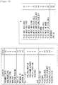
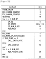
- a broadcast signal receiver for processing a broadcast signal including signaling information comprises a constellation mapper for symbol-demapping by using the signaling information as LLR values; a bit deinterleaver for bit multiplexing and block deinterleaving of the signaling information; an FEC decoder for FEC decoding the signaling information; and a descrambler for descrambling the signaling information, wherein the FEC decoder further comprises a zero inserting/parity inserting unit for inserting shortened zero bits and punctured parity bits into the signaling information; an LDPC decoder for LDPC decoding the signaling information; and a BCH decoder for removing zero bits of the signaling information and BCH decoding the signaling information.
- the zero inserting and parity inserting unit inserts LLRs of infinite values as the zero bits, and inserts LLRs of zero values as the parity bits.
- parity bits included in the signaling information are split into at least one of bit group units and permuted on the basis of the bit group units.
- the zero inserting and parity inserting unit inserts LLRs of zero values into the positions of punctured, last parity bits among the permuted parity bits of bit group units.
- the signaling information is characterized such that the zero bits are padded in bit group units according to a shortening pattern order and the BCH encoded signaling information is padded sequentially into the bit positions which are not padded with the zero bits.
- the zero bits are padded to fill up the LDPC information bits in case the number of BCH encoded bits is smaller than the number of LDPC information bits.
- the signaling information includes information for configuring physical layer parameters, L1 static information with a fixed length, and L1 dynamic information with a variable length.
- a method for receiving a broadcast signal comprises performing symbol-demapping of the signaling information to LLR values; performing bit multiplexing and block interleaving on the signaling information; FEC decoding the signaling information; and descrambling the signaling information, wherein the FEC decoding further comprises inserting shortened zero bits and punctured parity bits into the signaling information; LDPC decoding the signaling information; and removing zero bits of the signaling information and BCH decoding the signaling information.
- the inserting zero bits and parity bits inserts LLRs of infinite values as the zero bits and LLRs of zero values as the parity bits.
- parity bits included in the signaling information are split into at least one of bit group units and permuted on the basis of the bit group units.
- the inserting zero bits and parity bits inserts LLRs of zero values into the positions of punctured, last parity bits among the permuted parity bits of bit group units.
- the signaling information is characterized such that the zero bits are padded in bit group units according to a shortening pattern order and the BCH encoded signaling information is padded sequentially into the bit positions which are not padded with the zero bits.
- the zero bits are padded to fill up the LDPC information bits in case the number of BCH encoded bits is smaller than the number of LDPC information bits.
- the signaling information includes information for configuring physical layer parameters, L1 static information with a fixed length, and L1 dynamic information with a variable length.
- the present invention can process data according to service characteristics to control QoS (Quality of Services) for each service or service component, thereby providing various broadcast services.
- QoS Quality of Services
- the present invention can achieve transmission flexibility by transmitting various broadcast services through the same RF signal bandwidth.
- the present invention can improve data transmission efficiency and increase robustness of transmission/reception of broadcast signals using a MIMO system.
- the present invention it is possible to provide broadcast signal transmission and reception methods and apparatus capable of receiving digital broadcast signals without error even with mobile reception equipment or in an indoor environment.
- the present invention provides apparatuses and methods for transmitting and receiving broadcast signals for future broadcast services.
- Future broadcast services include a terrestrial broadcast service, a mobile broadcast service, a UHDTV service, etc.
- the present invention may process broadcast signals for the future broadcast services through non-MIMO (Multiple Input Multiple Output) or MIMO according to one embodiment.
- a non-MIMO scheme according to an embodiment of the present invention may include a MISO (Multiple Input Single Output) scheme, a SISO (Single Input Single Output) scheme, etc.
- MISO or MIMO uses two antennas in the following for convenience of description, the present invention is applicable to systems using two or more antennas.
- the present invention may defines three physical layer (PL) profiles (base, handheld and advanced profiles) each optimized to minimize receiver complexity while attaining the performance required for a particular use case.
- the physical layer (PHY) profiles are subsets of all configurations that a corresponding receiver should implement.
- the three PHY profiles share most of the functional blocks but differ slightly in specific blocks and/or parameters. Additional PHY profiles can be defined in the future. For the system evolution, future profiles can also be multiplexed with the existing profiles in a single RF channel through a future extension frame (FEF). The details of each PHY profile are described below.
- FEF future extension frame
- the base profile represents a main use case for fixed receiving devices that are usually connected to a roof-top antenna.
- the base profile also includes portable devices that could be transported to a place but belong to a relatively stationary reception category. Use of the base profile could be extended to handheld devices or even vehicular by some improved implementations, but those use cases are not expected for the base profile receiver operation.
- Target SNR range of reception is from approximately 10 to 20dB, which includes the 15dB SNR reception capability of the existing broadcast system (e.g. ATSC A/53).
- the receiver complexity and power consumption is not as critical as in the battery-operated handheld devices, which will use the handheld profile.
- Key system parameters for the base profile are listed in below table 1.
- Table 1 LDPC codeword length 16K, 64K bits Constellation size 4 ⁇ 10 bpcu (bits per channel use) Time de-interleaving memory size ⁇ 2 19 data cells Pilot patterns Pilot pattern for fixed reception FFT size 16K, 32K points
- the handheld profile is designed for use in handheld and vehicular devices that operate with battery power.
- the devices can be moving with pedestrian or vehicle speed.
- the power consumption as well as the receiver complexity is very important for the implementation of the devices of the handheld profile.
- the target SNR range of the handheld profile is approximately 0 to 10dB, but can be configured to reach below 0dB when intended for deeper indoor reception.
- the advanced profile provides highest channel capacity at the cost of more implementation complexity.
- This profile requires using MIMO transmission and reception, and UHDTV service is a target use case for which this profile is specifically designed.
- the increased capacity can also be used to allow an increased number of services in a given bandwidth, e.g., multiple SDTV or HDTV services.
- the target SNR range of the advanced profile is approximately 20 to 30dB.
- MIMO transmission may initially use existing elliptically-polarized transmission equipment, with extension to full-power cross-polarized transmission in the future.
- Key system parameters for the advanced profile are listed in below table 3.
- Table 3 LDPC codeword length 16K, 64K bits Constellation size 8 ⁇ 12 bpcu Time de-interleaving memory size ⁇ 2 19 data cells Pilot patterns Pilot pattern for fixed reception FFT size 16K, 32K points
- the base profile can be used as a profile for both the terrestrial broadcast service and the mobile broadcast service. That is, the base profile can be used to define a concept of a profile which includes the mobile profile. Also, the advanced profile can be divided advanced profile for a base profile with MIMO and advanced profile for a handheld profile with MIMO. Moreover, the three profiles can be changed according to intention of the designer.
- auxiliary stream sequence of cells carrying data of as yet undefined modulation and coding, which may be used for future extensions or as required by broadcasters or network operators
- base data pipe data pipe that carries service signaling data baseband frame (or BBFRAME): set of Kbch bits which form the input to one FEC encoding process (BCH and LDPC encoding) cell: modulation value that is carried by one carrier of the OFDM transmission coded block: LDPC-encoded block of PLS 1 data or one of the LDPC-encoded blocks of PLS2 data data pipe: logical channel in the physical layer that carries service data or related metadata, which may carry one or multiple service(s) or service component(s).
- data pipe unit a basic unit for allocating data cells to a DP in a frame.
- data symbol OFDM symbol in a frame which is not a preamble symbol (the frame signaling symbol and frame edge symbol is included in the data symbol)
- DP_ID this 8 bit field identifies uniquely a DP within the system identified by the SYSTEM_ID dummy cell: cell carrying a pseudo random value used to fill the remaining capacity not used for PLS signaling, DPs or auxiliary streams emergency alert channel: part of a frame that carries EAS information data frame: physical layer time slot that starts with a preamble and ends with a frame edge symbol frame repetition unit: a set of frames belonging to same or different physical layer profile including a FEF, which is repeated eight times in a super-frame fast information channel: a logical channel in a frame that carries the mapping information between a service and the corresponding base DP
- FECBLOCK set of LDPC-encoded bits of a DP data
- FFT size nominal FFT
- future extension frame physical layer time slot within the super-frame that could be used for future extension, which starts with a preamble Futurecast UTB system: proposed physical layer broadcasting system, of which the input is one or more MPEG2-TS or IP or general stream(s) and of which the output is an RF signal input stream: A stream of data for an ensemble of services delivered to the end users by the system.
- a preamble Futurecast UTB system proposed physical layer broadcasting system, of which the input is one or more MPEG2-TS or IP or general stream(s) and of which the output is an RF signal input stream: A stream of data for an ensemble of services delivered to the end users by the system.
- PLS physical layer signaling data consisting of PLS1 and PLS2
- PLS 1 a first set of PLS data carried in the FSS symbols having a fixed size, coding and modulation, which carries basic information about the system as well as the parameters needed to decode the PLS2
- PLS 1 data remains constant for the duration of a frame-group.
- PLS2 a second set of PLS data transmitted in the FSS symbol, which carries more detailed PLS data about the system and the DPs PLS2 dynamic data: PLS2 data that may dynamically change frame-by-frame PLS2 static data: PLS2 data that remains static for the duration of a frame-group preamble signaling data: signaling data carried by the preamble symbol and used to identify the basic mode of the system preamble symbol: fixed-length pilot symbol that carries basic PLS data and is located in the beginning of a frame NOTE: The preamble symbol is mainly used for fast initial band scan to detect the system signal, its timing, frequency offset, and FFT size.
- time interleaving block set of cells within which time interleaving is carried out, corresponding to one use of the time interleaver memory
- TI group unit over which dynamic capacity allocation for a particular DP is carried out, made up of an integer, dynamically varying number of XFECBLOCKs
- the TI group may be mapped directly to one frame or may be mapped to multiple frames. It may contain one or more TI blocks.
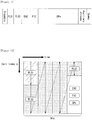
- FIG. 1 illustrates a structure of an apparatus for transmitting broadcast signals for future broadcast services according to an embodiment of the present invention.
- the apparatus for transmitting broadcast signals for future broadcast services can include an input formatting block 1000, a BICM (Bit interleaved coding & modulation) block 1010, a frame structure block 1020, an OFDM (Orthogonal Frequency Division Multiplexing) generation block 1030 and a signaling generation block 1040.
- BICM Bit interleaved coding & modulation
- OFDM Orthogonal Frequency Division Multiplexing
- IP stream/packets and MPEG2-TS are the main input formats, other stream types are handled as General Streams.
- Management Information is input to control the scheduling and allocation of the corresponding bandwidth for each input stream.
- One or multiple TS stream(s), IP stream(s) and/or General Stream(s) inputs are simultaneously allowed.
- the input formatting block 1000 can demultiplex each input stream into one or multiple data pipe(s), to each of which an independent coding and modulation is applied.
- the data pipe (DP) is the basic unit for robustness control, thereby affecting quality-of-service (QoS).
- QoS quality-of-service
- One or multiple service(s) or service component(s) can be carried by a single DP. Details of operations of the input formatting block 1000 will be described later.
- the data pipe is a logical channel in the physical layer that carries service data or related metadata, which may carry one or multiple service(s) or service component(s).
- the data pipe unit a basic unit for allocating data cells to a DP in a frame.
- parity data is added for error correction and the encoded bit streams are mapped to complex-value constellation symbols.
- the symbols are interleaved across a specific interleaving depth that is used for the corresponding DP.
- MIMO encoding is performed in the BICM block 1010 and the additional data path is added at the output for MIMO transmission. Details of operations of the BICM block 1010 will be described later.
- the Frame Building block 1020 can map the data cells of the input DPs into the OFDM symbols within a frame. After mapping, the frequency interleaving is used for frequency-domain diversity, especially to combat frequency-selective fading channels. Details of operations of the Frame Building block 1020 will be described later.
- the OFDM Generation block 1030 can apply conventional OFDM modulation having a cyclic prefix as guard interval. For antenna space diversity, a distributed MISO scheme is applied across the transmitters. In addition, a Peak-to-Average Power Reduction (PAPR) scheme is performed in the time domain. For flexible network planning, this proposal provides a set of various FFT sizes, guard interval lengths and corresponding pilot patterns. Details of operations of the OFDM Generation block 1030 will be described later.
- PAPR Peak-to-Average Power Reduction
- the Signaling Generation block 1040 can create physical layer signaling information used for the operation of each functional block. This signaling information is also transmitted so that the services of interest are properly recovered at the receiver side. Details of operations of the Signaling Generation block 1040 will be described later.
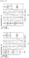
- FIGS. 2 , 3 and 4 illustrate the input formatting block 1000 according to embodiments of the present invention. A description will be given of each figure.
- FIG. 2 illustrates an input formatting block according to one embodiment of the present invention.
- FIG. 2 shows an input formatting module when the input signal is a single input stream.
- the input formatting block illustrated in FIG. 2 corresponds to an embodiment of the input formatting block 1000 described with reference to FIG. 1 .
- the input to the physical layer may be composed of one or multiple data streams. Each data stream is carried by one DP.
- the mode adaptation modules slice the incoming data stream into data fields of the baseband frame (BBF).
- BBF baseband frame
- the system supports three types of input data streams: MPEG2-TS, Internet protocol (IP) and Generic stream (GS).
- MPEG2-TS is characterized by fixed length (188 byte) packets with the first byte being a sync-byte (0x47).
- An IP stream is composed of variable length IP datagram packets, as signaled within IP packet headers.
- the system supports both IPv4 and IPv6 for the IP stream.
- GS may be composed of variable length packets or constant length packets, signaled within encapsulation packet headers.
- the Input Stream Splitter splits the input TS, IP, GS streams into multiple service or service component (audio, video, etc.) streams.
- the mode adaptation module 2010 is comprised of a CRC Encoder, BB (baseband) Frame Slicer, and BB Frame Header Insertion block.
- the CRC Encoder provides three kinds of CRC encoding for error detection at the user packet (UP) level, i.e., CRC-8, CRC-16, and CRC-32.
- the computed CRC bytes are appended after the UP.
- CRC-8 is used for TS stream and CRC-32 for IP stream. If the GS stream doesn't provide the CRC encoding, the proposed CRC encoding should be applied.
- the BB Frame Slicer maps the input into an internal logical-bit format.
- the first received bit is defined to be the MSB.
- the BB Frame Slicer allocates a number of input bits equal to the available data field capacity.
- the UP packet stream is sliced to fit the data field of BBF.
- BB Frame Header Insertion block can insert fixed length BBF header of 2 bytes is inserted in front of the BB Frame.
- the BBF header is composed of STUFFI (1 bit), SYNCD (13 bits), and RFU (2 bits).
- BBF can have an extension field (1 or 3 bytes) at the end of the 2-byte BBF header.
- the stream adaptation 2010 is comprised of stuffing insertion block and BB scrambler.
- the stuffing insertion block can insert stuffing field into a payload of a BB frame. If the input data to the stream adaptation is sufficient to fill a BB-Frame, STUFFI is set to '0' and the BBF has no stuffing field. Otherwise STUFFI is set to '1' and the stuffing field is inserted immediately after the BBF header.
- the stuffing field comprises two bytes of the stuffing field header and a variable size of stuffing data.
- the BB scrambler scrambles complete BBF for energy dispersal.
- the scrambling sequence is synchronous with the BBF.
- the scrambling sequence is generated by the feed-back shift register.
- the PLS generation block 2020 can generate physical layer signaling (PLS) data.
- PLS provides the receiver with a means to access physical layer DPs.
- the PLS data consists of PLS 1 data and PLS2 data.
- the PLS1 data is a first set of PLS data carried in the FSS symbols in the frame having a fixed size, coding and modulation, which carries basic information about the system as well as the parameters needed to decode the PLS2 data.
- the PLS1 data provides basic transmission parameters including parameters required to enable the reception and decoding of the PLS2 data. Also, the PLS 1 data remains constant for the duration of a frame-group.
- the PLS2 data is a second set of PLS data transmitted in the FSS symbol, which carries more detailed PLS data about the system and the DPs.
- the PLS2 contains parameters that provide sufficient information for the receiver to decode the desired DP.
- the PLS2 signaling further consists of two types of parameters, PLS2 Static data (PLS2-STAT data) and PLS2 dynamic data (PLS2-DYN data).
- PLS2 Static data is PLS2 data that remains static for the duration of a frame-group and the PLS2 dynamic data is PLS2 data that may dynamically change frame-by-frame.
- the PLS scrambler 2030 can scramble the generated PLS data for energy dispersal.
- FIG. 3 illustrates an input formatting block according to another embodiment of the present invention.
- the input formatting block illustrated in FIG. 3 corresponds to an embodiment of the input formatting block 1000 described with reference to FIG. 1 .
- FIG. 3 shows a mode adaptation block of the input formatting block when the input signal corresponds to multiple input streams.
- the mode adaptation block of the input formatting block for processing the multiple input streams can independently process the multiple input streams.
- the mode adaptation block for respectively processing the multiple input streams can include an input stream splitter 3000, an input stream synchronizer 3010, a compensating delay block 3020, a null packet deletion block 3030, a head compression block 3040, a CRC encoder 3050, a BB frame slicer 3060 and a BB header insertion block 3070. Description will be given of each block of the mode adaptation block.
- Operations of the CRC encoder 3050, BB frame slicer 3060 and BB header insertion block 3070 correspond to those of the CRC encoder, BB frame slicer and BB header insertion block described with reference to FIG. 2 and thus description thereof is omitted.
- the input stream splitter 3000 can split the input TS, IP, GS streams into multiple service or service component (audio, video, etc.) streams.
- the input stream synchronizer 3010 may be referred as ISSY.
- the ISSY can provide suitable means to guarantee Constant Bit Rate (CBR) and constant end-to-end transmission delay for any input data format.
- CBR Constant Bit Rate
- the ISSY is always used for the case of multiple DPs carrying TS, and optionally used for multiple DPs carrying GS streams.
- the compensating delay block 3020 can delay the split TS packet stream following the insertion of ISSY information to allow a TS packet recombining mechanism without requiring additional memory in the receiver.
- the null packet deletion block 3030 is used only for the TS input stream case.
- Some TS input streams or split TS streams may have a large number of null-packets present in order to accommodate VBR (variable bit-rate) services in a CBR TS stream.
- null-packets can be identified and not transmitted.
- removed null-packets can be re-inserted in the exact place where they were originally by reference to a deleted null-packet (DNP) counter that is inserted in the transmission, thus guaranteeing constant bit-rate and avoiding the need for time-stamp (PCR) updating.
- DNP deleted null-packet
- the head compression block 3040 can provide packet header compression to increase transmission efficiency for TS or IP input streams. Because the receiver can have a priori information on certain parts of the header, this known information can be deleted in the transmitter.
- the receiver For Transport Stream, the receiver has a-priori information about the sync-byte configuration (0x47) and the packet length (188 Byte). If the input TS stream carries content that has only one PID, i.e., for only one service component (video, audio, etc.) or service subcomponent (SVC base layer, SVC enhancement layer, MVC base view or MVC dependent views), TS packet header compression can be applied (optionally) to the Transport Stream. IP packet header compression is used optionally if the input steam is an IP stream.
- FIG. 4 illustrates an input formatting block according to another embodiment of the present invention.
- the input formatting block illustrated in FIG. 4 corresponds to an embodiment of the input formatting block 1000 described with reference to FIG. 1 .
- FIG. 4 illustrates a stream adaptation block of the input formatting module when the input signal corresponds to multiple input streams.
- the mode adaptation block for respectively processing the multiple input streams can include a scheduler 4000, an 1-Frame delay block 4010, a stuffing insertion block 4020, an in-band signaling 4030, a BB Frame scrambler 4040, a PLS generation block 4050 and a PLS scrambler 4060. Description will be given of each block of the stream adaptation block.
- Operations of the stuffing insertion block 4020, the BB Frame scrambler 4040, the PLS generation block 4050 and the PLS scrambler 4060 correspond to those of the stuffing insertion block, BB scrambler, PLS generation block and the PLS scrambler described with reference to FIG. 2 and thus description thereof is omitted.
- the scheduler 4000 can determine the overall cell allocation across the entire frame from the amount of FECBLOCKs of each DP. Including the allocation for PLS, EAC and FIC, the scheduler generate the values of PLS2-DYN data, which is transmitted as in-band signaling or PLS cell in FSS of the frame. Details of FECBLOCK, EAC and FIC will be described later.
- the 1-Frame delay block 4010 can delay the input data by one transmission frame such that scheduling information about the next frame can be transmitted through the current frame for in-band signaling information to be inserted into the DPs.
- the in-band signaling 4030 can insert un-delayed part of the PLS2 data into a DP of a frame.
- FIG. 5 illustrates a BICM block according to an embodiment of the present invention.
- the BICM block illustrated in FIG. 5 corresponds to an embodiment of the BICM block 1010 described with reference to FIG. 1 .
- the apparatus for transmitting broadcast signals for future broadcast services can provide a terrestrial broadcast service, mobile broadcast service, UHDTV service, etc.
- the a BICM block according to an embodiment of the present invention can independently process DPs input thereto by independently applying SISO, MISO and MIMO schemes to the data pipes respectively corresponding to data paths. Consequently, the apparatus for transmitting broadcast signals for future broadcast services according to an embodiment of the present invention can control QoS for each service or service component transmitted through each DP.
- the BICM block shared by the base profile and the handheld profile and the BICM block of the advanced profile can include plural processing blocks for processing each DP.
- a processing block 5000 of the BICM block for the base profile and the handheld profile can include a Data FEC encoder 5010, a bit interleaver 5020, a constellation mapper 5030, an SSD (Signal Space Diversity) encoding block 5040 and a time interleaver 5050.
- the Data FEC encoder 5010 can perform the FEC encoding on the input BBF to generate FECBLOCK procedure using outer coding (BCH), and inner coding (LDPC).
- BCH outer coding
- LDPC inner coding
- the outer coding (BCH) is optional coding method. Details of operations of the Data FEC encoder 5010 will be described later.
- the bit interleaver 5020 can interleave outputs of the Data FEC encoder 5010 to achieve optimized performance with combination of the LDPC codes and modulation scheme while providing an efficiently implementable structure. Details of operations of the bit interleaver 5020 will be described later.
- the constellation mapper 5030 can modulate each cell word from the bit interleaver 5020 in the base and the handheld profiles, or cell word from the Cell-word demultiplexer 5010-1 in the advanced profile using either QPSK, QAM-16, non-uniform QAM (NUQ-64, NUQ-256, NUQ-1024) or non-uniform constellation (NUC-16, NUC-64, NUC-256, NUC-1024) to give a power-normalized constellation point, el.
- This constellation mapping is applied only for DPs. Observe that QAM-16 and NUQs are square shaped, while NUCs have arbitrary shape. When each constellation is rotated by any multiple of 90 degrees, the rotated constellation exactly overlaps with its original one.
- the SSD encoding block 5040 can precode cells in two (2D), three (3D), and four (4D) dimensions to increase the reception robustness under difficult fading conditions.
- the time interleaver 5050 can operates at the DP level.
- the parameters of time interleaving (TI) may be set differently for each DP. Details of operations of the time interleaver 5050 will be described later.
- a processing block 5000-1 of the BICM block for the advanced profile can include the Data FEC encoder, bit interleaver, constellation mapper, and time interleaver. However, the processing block 5000-1 is distinguished from the processing block 5000 further includes a cell-word demultiplexer 5010-1 and a MIMO encoding block 5020-1.
- the operations of the Data FEC encoder, bit interleaver, constellation mapper, and time interleaver in the processing block 5000-1 correspond to those of the Data FEC encoder 5010, bit interleaver 5020, constellation mapper 5030, and time interleaver 5050 described and thus description thereof is omitted.
- the cell-word demultiplexer 5010-1 is used for the DP of the advanced profile to divide the single cell-word stream into dual cell-word streams for MIMO processing. Details of operations of the cell-word demultiplexer 5010-1 will be described later.
- the MIMO encoding block 5020-1 can processing the output of the cell-word demultiplexer 5010-1 using MIMO encoding scheme.
- the MIMO encoding scheme was optimized for broadcasting signal transmission.
- the MIMO technology is a promising way to get a capacity increase but it depends on channel characteristics. Especially for broadcasting, the strong LOS component of the channel or a difference in the received signal power between two antennas caused by different signal propagation characteristics makes it difficult to get capacity gain from MIMO.
- the proposed MIMO encoding scheme overcomes this problem using a rotation-based pre-coding and phase randomization of one of the MIMO output signals.
- MIMO encoding is intended for a 2x2 MIMO system requiring at least two antennas at both the transmitter and the receiver.
- Two MIMO encoding modes are defined in this proposal; full-rate spatial multiplexing (FR-SM) and full-rate full-diversity spatial multiplexing (FRFD-SM).
- FR-SM full-rate spatial multiplexing
- FRFD-SM full-rate full-diversity spatial multiplexing
- the FR-SM encoding provides capacity increase with relatively small complexity increase at the receiver side while the FRFD-SM encoding provides capacity increase and additional diversity gain with a great complexity increase at the receiver side.
- the proposed MIMO encoding scheme has no restriction on the antenna polarity configuration.
- MIMO processing is required for the advanced profile frame, which means all DPs in the advanced profile frame are processed by the MIMO encoder. MIMO processing is applied at DP level. Pairs of the Constellation Mapper outputs NUQ (e1,i and e2,i) are fed to the input of the MIMO Encoder. Paired MIMO Encoder output (g1,i and g2,i) is transmitted by the same carrier k and OFDM symbol 1 of their respective TX antennas.
- FIG. 6 illustrates a BICM block according to another embodiment of the present invention.
- the BICM block illustrated in FIG. 6 corresponds to an embodiment of the BICM block 1010 described with reference to FIG. 1 .
- FIG. 6 illustrates a BICM block for protection of physical layer signaling (PLS), emergency alert channel (EAC) and fast information channel (FIC).
- PLS physical layer signaling
- EAC emergency alert channel
- FIC fast information channel
- the BICM block for protection of PLS, EAC and FIC can include a PLS FEC encoder 6000, a bit interleaver 6010, a constellation mapper 6020 and time interleaver 6030.
- the PLS FEC encoder 6000 can include a scrambler, BCH encoding/zero insertion block, LDPC encoding block and LDPC parity punturing block. Description will be given of each block of the BICM block.
- the PLS FEC encoder 6000 can encode the scrambled PLS 1/2 data, EAC and FIC section.
- the scrambler can scramble PLS 1 data and PLS2 data before BCH encoding and shortened and punctured LDPC encoding.
- the BCH encoding/zero insertion block can perform outer encoding on the scrambled PLS 1/2 data using the shortened BCH code for PLS protection and insert zero bits after the BCH encoding.
- the output bits of the zero insertion may be permutted before LDPC encoding.
- the LDPC encoding block can encode the output of the BCH encoding/zero insertion block using LDPC code.
- C ldpc parity bits, Pldpc are encoded systematically from each zero-inserted PLS information block, I ldpc and appended after it.
- the LDPC code parameters for PLS1 and PLS2 are as following table 4.
- the LDPC parity punturing block can perform puncturing on the PLS 1 data and PLS 2 data.
- the bit interleaver 6010 can interleave the each shortened and punctured PLS 1 data and PLS2 data.
- the constellation mapper 6020 can map the bit ineterlaeved PLS1 data and PLS2 data onto constellations.
- the time interleaver 6030 can interleave the mapped PLS1 data and PLS2 data.
- FIG. 7 illustrates a frame building block according to one embodiment of the present invention.
- the frame building block illustrated in FIG. 7 corresponds to an embodiment of the frame building block 1020 described with reference to FIG. 1 .
- the frame building block can include a delay compensation block 7000, a cell mapper 7010 and a frequency interleaver 7020. Description will be given of each block of the frame building block.
- the delay compensation block 7000 can adjust the timing between the data pipes and the corresponding PLS data to ensure that they are co-timed at the transmitter end.
- the PLS data is delayed by the same amount as data pipes are by addressing the delays of data pipes caused by the Input Formatting block and BICM block.
- the delay of the BICM block is mainly due to the time interleaver 5050.
- In-band signaling data carries information of the next TI group so that they are carried one frame ahead of the DPs to be signaled.
- the Delay Compensating block delays in-band signaling data accordingly.
- the cell mapper 7010 can map PLS, EAC, FIC, DPs, auxiliary streams and dummy cells into the active carriers of the OFDM symbols in the frame.
- the basic function of the cell mapper 7010 is to map data cells produced by the TIs for each of the DPs, PLS cells, and EAC/FIC cells, if any, into arrays of active OFDM cells corresponding to each of the OFDM symbols within a frame.
- Service signaling data (such as PSI(program specific information)/SI) can be separately gathered and sent by a data pipe.
- the Cell Mapper operates according to the dynamic information produced by the scheduler and the configuration of the frame structure. Details of the frame will be described later.
- the frequency interleaver 7020 can randomly interleave data cells received from the cell mapper 7010 to provide frequency diversity. Also, the frequency interleaver 7020 can operate on very OFDM symbol pair comprised of two sequential OFDM symbols using a different interleaving-seed order to get maximum interleaving gain in a single frame. Details of operations of the frequency interleaver 7020 will be described later.
- FIG. 8 illustrates an OFMD generation block according to an embodiment of the present invention.
- the OFMD generation block illustrated in FIG. 8 corresponds to an embodiment of the OFMD generation block 1030 described with reference to FIG. 1 .
- the OFDM generation block modulates the OFDM carriers by the cells produced by the Frame Building block, inserts the pilots, and produces the time domain signal for transmission. Also, this block subsequently inserts guard intervals, and applies PAPR (Peak-to-Average Power Radio) reduction processing to produce the final RF signal.
- PAPR Peak-to-Average Power Radio
- the frame building block can include a pilot and reserved tone insertion block 8000, a 2D-eSFN encoding block 8010, an IFFT (Inverse Fast Fourier Transform) block 8020, a PAPR reduction block 8030, a guard interval insertion block 8040, a preamble insertion block 8050, other system insertion block 8060 and a DAC block 8070. Description will be given of each block of the frame building block.
- IFFT Inverse Fast Fourier Transform
- the pilot and reserved tone insertion block 8000 can insert pilots and the reserved tone.
- pilots which have transmitted values known a priori in the receiver.
- the information of pilot cells is made up of scattered pilots, continual pilots, edge pilots, FSS (frame signaling symbol) pilots and FES (frame edge symbol) pilots.
- Each pilot is transmitted at a particular boosted power level according to pilot type and pilot pattern.
- the value of the pilot information is derived from a reference sequence, which is a series of values, one for each transmitted carrier on any given symbol.
- the pilots can be used for frame synchronization, frequency synchronization, time synchronization, channel estimation, and transmission mode identification, and also can be used to follow the phase noise.
- Reference information, taken from the reference sequence, is transmitted in scattered pilot cells in every symbol except the preamble, FSS and FES of the frame.
- Continual pilots are inserted in every symbol of the frame. The number and location of continual pilots depends on both the FFT size and the scattered pilot pattern.
- the edge carriers are edge pilots in every symbol except for the preamble symbol. They are inserted in order to allow frequency interpolation up to the edge of the spectrum.
- FSS pilots are inserted in FSS(s) and FES pilots are inserted in FES. They are inserted in order to allow time interpolation up to the edge of the frame.
- the system according to an embodiment of the present invention supports the SFN network, where distributed MISO scheme is optionally used to support very robust transmission mode.
- the 2D-eSFN is a distributed MISO scheme that uses multiple TX antennas, each of which is located in the different transmitter site in the SFN network.
- the 2D-eSFN encoding block 8010 can process a 2D-eSFN processing to distorts the phase of the signals transmitted from multiple transmitters, in order to create both time and frequency diversity in the SFN configuration. Hence, burst errors due to low flat fading or deep-fading for a long time can be mitigated.
- the IFFT block 8020 can modulate the output from the 2D-eSFN encoding block 8010 using OFDM modulation scheme. Any cell in the data symbols which has not been designated as a pilot (or as a reserved tone) carries one of the data cells from the frequency interleaver. The cells are mapped to OFDM carriers.
- the PAPR reduction block 8030 can perform a PAPR reduction on input signal using various PAPR reduction algorithm in the time domain.
- the guard interval insertion block 8040 can insert guard intervals and the preamble insertion block 8050 can insert preamble in front of the signal. Details of a structure of the preamble will be described later.
- the other system insertion block 8060 can multiplex signals of a plurality of broadcast transmission/reception systems in the time domain such that data of two or more different broadcast transmission/reception systems providing broadcast services can be simultaneously transmitted in the same RF signal bandwidth.
- the two or more different broadcast transmission/reception systems refer to systems providing different broadcast services.
- the different broadcast services may refer to a terrestrial broadcast service, mobile broadcast service, etc. Data related to respective broadcast services can be transmitted through different frames.
- the DAC block 8070 can convert an input digital signal into an analog signal and output the analog signal.
- the signal output from the DAC block 7800 can be transmitted through multiple output antennas according to the physical layer profiles.
- a Tx antenna according to an embodiment of the present invention can have vertical or horizontal polarity.
- FIG. 9 illustrates a structure of an apparatus for receiving broadcast signals for future broadcast services according to an embodiment of the present invention.
- the apparatus for receiving broadcast signals for future broadcast services can correspond to the apparatus for transmitting broadcast signals for future broadcast services, described with reference to FIG. 1 .
- the apparatus for receiving broadcast signals for future broadcast services can include a synchronization & demodulation module 9000, a frame parsing module 9010, a demapping & decoding module 9020, an output processor 9030 and a signaling decoding module 9040. A description will be given of operation of each module of the apparatus for receiving broadcast signals.
- the synchronization & demodulation module 9000 can receive input signals through m Rx antennas, perform signal detection and synchronization with respect to a system corresponding to the apparatus for receiving broadcast signals and carry out demodulation corresponding to a reverse procedure of the procedure performed by the apparatus for transmitting broadcast signals.
- the frame parsing module 9010 can parse input signal frames and extract data through which a service selected by a user is transmitted. If the apparatus for transmitting broadcast signals performs interleaving, the frame parsing module 9010 can carry out deinterleaving corresponding to a reverse procedure of interleaving. In this case, the positions of a signal and data that need to be extracted can be obtained by decoding data output from the signaling decoding module 9040 to restore scheduling information generated by the apparatus for transmitting broadcast signals.
- the demapping & decoding module 9020 can convert the input signals into bit domain data and then deinterleave the same as necessary.
- the demapping & decoding module 9020 can perform demapping for mapping applied for transmission efficiency and correct an error generated on a transmission channel through decoding.
- the demapping & decoding module 9020 can obtain transmission parameters necessary for demapping and decoding by decoding the data output from the signaling decoding module 9040.
- the output processor 9030 can perform reverse procedures of various compression/signal processing procedures which are applied by the apparatus for transmitting broadcast signals to improve transmission efficiency.
- the output processor 9030 can acquire necessary control information from data output from the signaling decoding module 9040.
- the output of the output processor 9030 corresponds to a signal input to the apparatus for transmitting broadcast signals and may be MPEG-TSs, IP streams (v4 or v6) and generic streams.
- the signaling decoding module 9040 can obtain PLS information from the signal demodulated by the synchronization & demodulation module 9000. As described above, the frame parsing module 9010, demapping & decoding module 9020 and output processor 9030 can execute functions thereof using the data output from the signaling decoding module 9040.
- FIG. 10 illustrates a frame structure according to an embodiment of the present invention.
- FIG. 10 shows an example configuration of the frame types and FRUs in a super-frame.
- (a) shows a super frame according to an embodiment of the present invention
- (b) shows FRU (Frame Repetition Unit) according to an embodiment of the present invention
- (c) shows frames of variable PHY profiles in the FRU
- (d) shows a structure of a frame.
- a super-frame may be composed of eight FRUs.
- the FRU is a basic multiplexing unit for TDM of the frames, and is repeated eight times in a super-frame.
- Each frame in the FRU belongs to one of the PHY profiles, (base, handheld, advanced) or FEF.
- the maximum allowed number of the frames in the FRU is four and a given PHY profile can appear any number of times from zero times to four times in the FRU (e.g., base, base, handheld, advanced).
- PHY profile definitions can be extended using reserved values of the PHY_PROFILE in the preamble, if required.
- the FEF part is inserted at the end of the FRU, if included.
- the minimum number of FEFs is 8 in a super-frame. It is not recommended that FEF parts be adjacent to each other.
- One frame is further divided into a number of OFDM symbols and a preamble. As shown in (d), the frame comprises a preamble, one or more frame signaling symbols (FSS), normal data symbols and a frame edge symbol (FES).
- FSS frame signaling symbols
- FES normal data symbols
- FES frame edge symbol
- the preamble is a special symbol that enables fast Futurecast UTB system signal detection and provides a set of basic transmission parameters for efficient transmission and reception of the signal. The detailed description of the preamble will be will be described later.
- the main purpose of the FSS(s) is to carry the PLS data.
- the FSS For fast synchronization and channel estimation, and hence fast decoding of PLS data, the FSS has more dense pilot pattern than the normal data symbol.
- the FES has exactly the same pilots as the FSS, which enables frequency-only interpolation within the FES and temporal interpolation, without extrapolation, for symbols immediately preceding the FES.
- FIG. 11 illustrates a signaling hierarchy structure of the frame according to an embodiment of the present invention.
- FIG. 11 illustrates the signaling hierarchy structure, which is split into three main parts: the preamble signaling data 11000, the PLS1 data 11010 and the PLS2 data 11020.
- the purpose of the preamble which is carried by the preamble symbol in every frame, is to indicate the transmission type and basic transmission parameters of that frame.
- the PLS1 enables the receiver to access and decode the PLS2 data, which contains the parameters to access the DP of interest.
- the PLS2 is carried in every frame and split into two main parts: PLS2-STAT data and PLS2-DYN data. The static and dynamic portion of PLS2 data is followed by padding, if necessary.
- FIG. 12 illustrates preamble signaling data according to an embodiment of the present invention.
- Preamble signaling data carries 21 bits of information that are needed to enable the receiver to access PLS data and trace DPs within the frame structure. Details of the preamble signaling data are as follows:
- FFT_SIZE This 2 bit field indicates the FFT size of the current frame within a frame-group, as described in below table 6. [Table 6] Value FFT size 00 8K FFT 01 16K FFT 10 32K FFT 11 Reserved
- GI_FRACTION This 3 bit field indicates the guard interval fraction value in the current super-frame, as described in below table 7. [Table 7] Value GI_FRACTION 000 1/5 001 1/10 010 1/20 011 1/40 100 1/80 101 1/160 110 ⁇ 111 Reserved
- EAC_FLAG This 1 bit field indicates whether the EAC is provided in the current frame. If this field is set to '1', emergency alert service (EAS) is provided in the current frame. If this field set to '0', EAS is not carried in the current frame. This field can be switched dynamically within a super-frame.
- EAS emergency alert service
- PILOT_MODE This 1-bit field indicates whether the pilot mode is mobile mode or fixed mode for the current frame in the current frame-group. If this field is set to '0', mobile pilot mode is used. If the field is set to '1', the fixed pilot mode is used.
- PAPR_FLAG This 1-bit field indicates whether PAPR reduction is used for the current frame in the current frame-group. If this field is set to value '1', tone reservation is used for PAPR reduction. If this field is set to '0', PAPR reduction is not used.
- FRU_CONFIGURE This 3-bit field indicates the PHY profile type configurations of the frame repetition units (FRU) that are present in the current super-frame. All profile types conveyed in the current super-frame are identified in this field in all preambles in the current super-frame.
- the 3-bit field has a different definition for each profile, as show in below table 8.
- FIG. 13 illustrates PLS 1 data according to an embodiment of the present invention.
- PLS 1 data provides basic transmission parameters including parameters required to enable the reception and decoding of the PLS2. As above mentioned, the PLS1 data remain unchanged for the entire duration of one frame-group.
- the detailed definition of the signaling fields of the PLS 1 data are as follows:
- NUM_FRAME_FRU This 2-bit field indicates the number of the frames per FRU.
- PAYLOAD_TYPE This 3-bit field indicates the format of the payload data carried in the frame-group. PAYLOAD_TYPE is signaled as shown in table 9. [Table 9] value Payload types 1XX TS stream is transmitted X1X IP stream is transmitted XX1 GS stream is transmitted
- NUM_FSS This 2-bit field indicates the number of FSS symbols in the current frame.
- SYSTEM_VERSION This 8-bit field indicates the version of the transmitted signal format.
- the SYSTEM_VERSION is divided into two 4-bit fields, which are a major version and a minor version.
- MSB four bits of SYSTEM_VERSION field indicate major version information.
- a change in the major version field indicates a non-backward-compatible change.
- the default value is '0000'.
- the value is set to '0000'.
- Minor version The LSB four bits of SYSTEM_VERSION field indicate minor version information. A change in the minor version field is backward-compatible.
- CELL_ID This is a 16-bit field which uniquely identifies a geographic cell in an ATSC network.
- An ATSC cell coverage area may consist of one or more frequencies, depending on the number of frequencies used per Futurecast UTB system. If the value of the CELL_ID is not known or unspecified, this field is set to '0'.
- NETWORK_ID This is a 16-bit field which uniquely identifies the current ATSC network.
- SYSTEM_ID This 16-bit field uniquely identifies the Futurecast UTB system within the ATSC network.
- the Futurecast UTB system is the terrestrial broadcast system whose input is one or more input streams (TS, IP, GS) and whose output is an RF signal.
- the Futurecast UTB system carries one or more PHY profiles and FEF, if any.
- the same Futurecast UTB system may carry different input streams and use different RF frequencies in different geographical areas, allowing local service insertion.
- the frame structure and scheduling is controlled in one place and is identical for all transmissions within a Futurecast UTB system.
- One or more Futurecast UTB systems may have the same SYSTEM_ID meaning that they all have the same physical layer structure and configuration.
- the following loop consists of FRU_PHY_PROFILE, FRU_FRAME_LENGTH, FRU_GI_FRACTION, and RESERVED which are used to indicate the FRU configuration and the length of each frame type.
- the loop size is fixed so that four PHY profiles (including a FEF) are signaled within the FRU. If NUM_FRAME_FRU is less than 4, the unused fields are filled with zeros.
- FRU_PHY_PROFILE This 3-bit field indicates the PHY profile type of the (i+1)th (i is the loop index) frame of the associated FRU. This field uses the same signaling format as shown in the table 8.
- FRU_FRAME_LENGTH This 2-bit field indicates the length of the (i+1)th frame of the associated FRU. Using FRU_FRAME_LENGTH together with FRU_GI_FRACTION, the exact value of the frame duration can be obtained.
- FRU_GI_FRACTION This 3-bit field indicates the guard interval fraction value of the (i+1)th frame of the associated FRU.
- FRU_GI_FRACTION is signaled according to the table 7.
- the following fields provide parameters for decoding the PLS2 data.
- PLS2_FEC_TYPE This 2-bit field indicates the FEC type used by the PLS2 protection.
- the FEC type is signaled according to table 10. The details of the LDPC codes will be described later. [Table 10] Content PLS2 FEC type 00 4K-1/4 and 7K-3/10 LDPC codes 01 ⁇ 11 Reserved
- PLS2_MOD This 3-bit field indicates the modulation type used by the PLS2.
- the modulation type is signaled according to table 11. [Table 11] Value PLS2_MODE 000 BPSK 001 QPSK 010 QAM-16 011 NUQ-64 100 ⁇ 111 Reserved
- PLS2_SIZE_CELL This 15-bit field indicates C total_partial_block , the size (specified as the number of QAM cells) of the collection of full coded blocks for PLS2 that is carried in the current frame-group. This value is constant during the entire duration of the current frame-group.
- PLS2_STAT_SIZE_BIT This 14-bit field indicates the size, in bits, of the PLS2-STAT for the current frame-group. This value is constant during the entire duration of the current frame-group.
- PLS2_DYN_SIZE_BIT This 14-bit field indicates the size, in bits, of the PLS2-DYN for the current frame-group. This value is constant during the entire duration of the current frame-group.
- PLS2_REP_FLAG This 1-bit flag indicates whether the PLS2 repetition mode is used in the current frame-group. When this field is set to value '1', the PLS2 repetition mode is activated. When this field is set to value '0', the PLS2 repetition mode is deactivated.
- PLS2_REP_SIZE_CELL This 15-bit field indicates C total_partial_block , the size (specified as the number of QAM cells) of the collection of partial coded blocks for PLS2 carried in every frame of the current frame-group, when PLS2 repetition is used. If repetition is not used, the value of this field is equal to 0. This value is constant during the entire duration of the current frame-group.
- PLS2_NEXT_FEC_TYPE This 2-bit field indicates the FEC type used for PLS2 that is carried in every frame of the next frame-group. The FEC type is signaled according to the table 10.
- PLS2_NEXT_MOD This 3-bit field indicates the modulation type used for PLS2 that is carried in every frame of the next frame-group. The modulation type is signaled according to the table 11.
- PLS2_NEXT_REP_FLAG This 1-bit flag indicates whether the PLS2 repetition mode is used in the next frame-group. When this field is set to value '1', the PLS2 repetition mode is activated. When this field is set to value '0', the PLS2 repetition mode is deactivated.
- PLS2_NEXT_REP_SIZE_CELL This 15-bit field indicates C total_full_block , The size (specified as the number of QAM cells) of the collection of full coded blocks for PLS2 that is carried in every frame of the next frame-group, when PLS2 repetition is used. If repetition is not used in the next frame-group, the value of this field is equal to 0. This value is constant during the entire duration of the current frame-group.
- PLS2_NEXT_REP_STAT_SIZE_BIT This 14-bit field indicates the size, in bits, of the PLS2-STAT for the next frame-group. This value is constant in the current frame-group.
- PLS2_NEXT_REP_DYN_SIZE_BIT This 14-bit field indicates the size, in bits, of the PLS2-DYN for the next frame-group. This value is constant in the current frame-group.
- PLS2_AP_MODE This 2-bit field indicates whether additional parity is provided for PLS2 in the current frame-group. This value is constant during the entire duration of the current frame-group.
- the below table 12 gives the values of this field. When this field is set to '00', additional parity is not used for the PLS2 in the current frame-group. [Table 12] Value PLS2-AP mode 00 AP is not provided 01 AP1 mode 10 ⁇ 11 Reserved
- PLS2_AP_SIZE_CELL This 15-bit field indicates the size (specified as the number of QAM cells) of the additional parity bits of the PLS2. This value is constant during the entire duration of the current frame-group.
- PLS2_NEXT_AP_MODE This 2-bit field indicates whether additional parity is provided for PLS2 signaling in every frame of next frame-group. This value is constant during the entire duration of the current frame-group.
- the table 12 defines the values of this field
- PLS2_NEXT_AP_SIZE_CELL This 15-bit field indicates the size (specified as the number of QAM cells) of the additional parity bits of the PLS2 in every frame of the next frame-group. This value is constant during the entire duration of the current frame-group.
- RESERVED This 32-bit field is reserved for future use.
- CRC_32 A 32-bit error detection code, which is applied to the entire PLS1 signaling.
- FIG. 14 illustrates PLS2 data according to an embodiment of the present invention.
- FIG. 14 illustrates PLS2-STAT data of the PLS2 data.
- the PLS2-STAT data are the same within a frame-group, while the PLS2-DYN data provide information that is specific for the current frame.
- AUX_FLAG This 1-bit field indicates whether the auxiliary stream(s) is used in the current frame-group. If this field is set to '1', the auxiliary stream is provided in the current frame. If this field set to '0', the auxiliary stream is not carried in the current frame. This value is constant during the entire duration of current frame-group.
- NUM_DP This 6-bit field indicates the number of DPs carried within the current frame. The value of this field ranges from 1 to 64, and the number of DPs is NUM_DP+1.
- DP_ID This 6-bit field identifies uniquely a DP within a PHY profile.
- DP_TYPE This 3-bit field indicates the type of the DP. This is signaled according to the below table 13. [Table 13] Value DP Type 000 DP Type 1 001 DP Type 2 010 ⁇ 111 reserved
- DP_GROUP_ID This 8-bit field identifies the DP group with which the current DP is associated. This can be used by a receiver to access the DPs of the service components associated with a particular service, which will have the same DP_GROUP_ID.
- BASE_DP_ID This 6-bit field indicates the DP carrying service signaling data (such as PSI/SI) used in the Management layer.
- the DP indicated by BASE_DP_ID may be either a normal DP carrying the service signaling data along with the service data or a dedicated DP carrying only the service signaling data
- DP_FEC_TYPE This 2-bit field indicates the FEC type used by the associated DP.
- the FEC type is signaled according to the below table 14. [Table 14] Value FEC_TYPE 00 16K LDPC 01 64K LDPC 10 ⁇ 11 Reserved
- DP_COD This 4-bit field indicates the code rate used by the associated DP.
- the code rate is signaled according to the below table 15. [Table 15] Value Code rate 0000 5/15 0001 6/15 0010 7/15 0011 8/15 0100 9/15 0101 10/15 0110 11/15 0111 12/15 1000 13/15 1001 ⁇ 1111 Reserved
- DP_MOD This 4-bit field indicates the modulation used by the associated DP. The modulation is signaled according to the below table 16. [Table 16] Value Modulation 0000 QPSK 0001 QAM-16 0010 NUQ-64 0011 NUQ-256 0100 NUQ-1024 0101 NUC-16 0110 NUC-64 0111 NUC-256 1000 NUC-1024 1001 ⁇ 1111 reserved
- DP_SSD_FLAG This 1-bit field indicates whether the SSD mode is used in the associated DP. If this field is set to value '1', SSD is used. If this field is set to value '0', SSD is not used.
- PHY_PROFILE is equal to '010', which indicates the advanced profile:
- DP_TI_TYPE This 1-bit field indicates the type of time-interleaving. A value of '0' indicates that one TI group corresponds to one frame and contains one or more TI-blocks. A value of '1' indicates that one TI group is carried in more than one frame and contains only one TI-block.
- DP_TI_LENGTH The use of this 2-bit field (the allowed values are only 1, 2, 4, 8) is determined by the values set within the DP_TI_TYPE field as follows:
- the allowed PI values with 2-bit field are defined in the below table 18. [Table 18] 2-bit field P t N TI 00 1 1 01 2 2 10 4 3 11 8 4
- DP_FRAME_INTERVAL This 2-bit field indicates the frame interval (I JUMP ) within the frame-group for the associated DP and the allowed values are 1, 2, 4, 8 (the corresponding 2-bit field is '00', '01', '10', or '11', respectively). For DPs that do not appear every frame of the frame-group, the value of this field is equal to the interval between successive frames. For example, if a DP appears on the frames 1, 5, 9, 13, etc., this field is set to '4'. For DPs that appear in every frame, this field is set to '1'.
- DP_TI_BYPASS This 1-bit field determines the availability of time interleaver 5050. If time interleaving is not used for a DP, it is set to '1'. Whereas if time interleaving is used it is set to '0'.
- DP_FIRST_FRAME_IDX This 5-bit field indicates the index of the first frame of the super-frame in which the current DP occurs.
- the value of DP_FIRST_FRAME_IDX ranges from 0 to 31
- DP_NUM_BLOCK_MAX This 10-bit field indicates the maximum value of DP_NUM_BLOCKS for this DP. The value of this field has the same range as DP_NUM BLOCKS.
- DP_PAYLOAD_TYPE This 2-bit field indicates the type of the payload data carried by the given DP.
- DP_PAYLOAD_TYPE is signaled according to the below table 19. [Table 19] Value Payload Type 00 TS. 01 IP 10 GS 11 reserved
- DP_INBAND_MODE This 2-bit field indicates whether the current DP carries in-band signaling information.
- the in-band signaling type is signaled according to the below table 20. [Table 20] Value In-band mode 00 In-band signaling is not carried. 01 INBAND-PLS is carried only 10 INBAND-ISSY is carried only 11 INBAND-PLS and INBAND-ISSY are carried
- DP_PROTOCOL_TYPE This 2-bit field indicates the protocol type of the payload carried by the given DP. It is signaled according to the below table 21 when input payload types are selected. [Table 21] Value If DP_PAYLOAD_TYPE Is TS If DP_PAYLOAD_TYPE Is IP If DP_PAYLOAD_TYPE Is GS 00 MPEG2-TS IPv4 (Note) 01 Reserved IPv6 Reserved 10 Reserved Reserved Reserved Reserved 11 Reserved Reserved Reserved
- DP_CRC_MODE This 2-bit field indicates whether CRC encoding is used in the Input Formatting block.
- the CRC mode is signaled according to the below table 22. [Table 22] Value CRC mode 00 Not used 01 CRC-8 10 CRC-16 11 CRC-32
- DNP_MODE This 2-bit field indicates the null-packet deletion mode used by the associated DP when DP_PAYLOAD_TYPE is set to TS ('00'). DNP_MODE is signaled according to the below table 23. If DP_PAYLOAD_TYPE is not TS ('00'), DNP_MODE is set to the value '00'. [Table 23] Value Null-packet deletion mode 00 Not used 01 DNP-NORMAL 10 DNP-OFFSET 11 reserved
- ISSY_MODE This 2-bit field indicates the ISSY mode used by the associated DP when DP_PAYLOAD_TYPE is set to TS ('00').
- the ISSY_MODE is signaled according to the below table 24 If DP_PAYLOAD_TYPE is not TS ('00'), ISSY_MODE is set to the value '00'. [Table 24] Value ISSY mode 00 Not used 01 ISSY-UP 10 ISSY-BBF 11 reserved
- HC_MODE_TS This 2-bit field indicates the TS header compression mode used by the associated DP when DP_PAYLOAD_TYPE is set to TS ('00').
- the HC_MODE_TS is signaled according to the below table 25. [Table 25] Value Header compression mode 00 HC_MODE_TS 1 01 HC_MODE_TS 2 10 HC_MODE_TS 3 11 HC_MODE_TS 4
- HC_MODE_IP This 2-bit field indicates the IP header compression mode when DP_PAYLOAD_TYPE is set to IP ( ⁇ 01').
- the HC_MODE_IP is signaled according to the below table 26. [Table 26] Value Header compression mode 00 No compression 01 HC_MODE_IP 1 10 ⁇ 11 reserved
- PID This 13-bit field indicates the PID number for TS header compression when DP_PAYLOAD_TYPE is set to TS ('00') and HC_MODE_TS is set to '01' or '10'.
- FIC_LENGTH_BYTE This 13-bit field indicates the length, in bytes, of the FIC.
- AUX_CONFIG_RFU This 8-bit field is reserved for future use.
- AUX_STREAM_TYPE This 4-bit is reserved for future use for indicating the type of the current auxiliary stream.
- AUX_PRIVATE_CONFIG This 28-bit field is reserved for future use for signaling auxiliary streams.
- FIG. 15 illustrates PLS2 data according to another embodiment of the present invention.
- FIG. 15 illustrates PLS2-DYN data of the PLS2 data.
- the values of the PLS2-DYN data may change during the duration of one frame-group, while the size of fields remains constant.
- PLS_CHANGE_COUNTER This 4-bit field indicates the number of super-frames ahead where the configuration will change. The next super-frame with changes in the configuration is indicated by the value signaled within this field. If this field is set to the value '0000', it means that no scheduled change is foreseen: e.g., value '1' indicates that there is a change in the next super-frame.
- FIC_CHANGE_COUNTER This 4-bit field indicates the number of super-frames ahead where the configuration (i.e., the contents of the FIC) will change. The next super-frame with changes in the configuration is indicated by the value signaled within this field. If this field is set to the value '0000', it means that no scheduled change is foreseen: e.g. value '0001' indicates that there is a change in the next super-frame..
- NUM_DP The following fields appear in the loop over NUM_DP, which describe the parameters associated with the DP carried in the current frame.
- DP_ID This 6-bit field indicates uniquely the DP within a PHY profile.
- DP_START This 15-bit (or 13-bit) field indicates the start position of the first of the DPs using the DPU addressing scheme.
- the DP_START field has differing length according to the PHY profile and FFT size as shown in the below table 27. [Table 27] PHY profile DP_START field size 64K 16K Base 13 bit 15 bit Handheld - 13 bit Advanced 13 bit 15 bit
- DP_NUM_BLOCK This 10-bit field indicates the number of FEC blocks in the current TI group for the current DP.
- the value of DP_NUM_BLOCK ranges from 0 to 1023
- the following fields indicate the FIC parameters associated with the EAC.
- EAC_FLAG This 1-bit field indicates the existence of the EAC in the current frame. This bit is the same value as the EAC_FLAG in the preamble.
- EAS_WAKE_UP_VERSION_NUM This 8-bit field indicates the version number of a wake-up indication.
- EAC_FLAG field is equal to '1', the following 12 bits are allocated for EAC_LENGTH_BYTE field. If the EAC_FLAG field is equal to '0', the following 12 bits are allocated for EAC_COUNTER.
- EAC_LENGTH_BYTE This 12-bit field indicates the length, in byte, of the EAC..
- EAC_COUNTER This 12-bit field indicates the number of the frames before the frame where the EAC arrives.
- CRC_32 A 32-bit error detection code, which is applied to the entire PLS2.
- FIG. 16 illustrates a logical structure of a frame according to an embodiment of the present invention.
- the PLS, EAC, FIC, DPs, auxiliary streams and dummy cells are mapped into the active carriers of the OFDM symbols in the frame.
- the PLS1 and PLS2 are first mapped into one or more FSS(s). After that, EAC cells, if any, are mapped immediately following the PLS field, followed next by FIC cells, if any.
- the DPs are mapped next after the PLS or EAC, FIC, if any. Type 1 DPs follows first, and Type 2 DPs next. The details of a type of the DP will be described later. In some case, DPs may carry some special data for EAS or service signaling data.
- auxiliary stream or streams follow the DPs, which in turn are followed by dummy cells. Mapping them all together in the above mentioned order, i.e. PLS, EAC, FIC, DPs, auxiliary streams and dummy data cells exactly fill the cell capacity in the frame.
- FIG. 17 illustrates PLS mapping according to an embodiment of the present invention.
- PLS cells are mapped to the active carriers of FSS(s). Depending on the number of cells occupied by PLS, one or more symbols are designated as FSS(s), and the number of FSS(s) N FSS is signaled by NUM_FSS in PLS1.
- the FSS is a special symbol for carrying PLS cells. Since robustness and latency are critical issues in the PLS, the FSS(s) has higher density of pilots allowing fast synchronization and frequency-only interpolation within the FSS.
- PLS cells are mapped to active carriers of the N FSS FSS(s) in a top-down manner as shown in an example in FIG. 17 .
- the PLS1 cells are mapped first from the first cell of the first FSS in an increasing order of the cell index.
- the PLS2 cells follow immediately after the last cell of the PLS1 and mapping continues downward until the last cell index of the first FSS. If the total number of required PLS cells exceeds the number of active carriers of one FSS, mapping proceeds to the next FSS and continues in exactly the same manner as the first FSS.
- DPs are carried next. If EAC, FIC or both are present in the current frame, they are placed between PLS and "normal" DPs.
- FIG. 18 illustrates EAC mapping according to an embodiment of the present invention.
- EAC is a dedicated channel for carrying EAS messages and links to the DPs for EAS. EAS support is provided but EAC itself may or may not be present in every frame. EAC, if any, is mapped immediately after the PLS2 cells. EAC is not preceded by any of the FIC, DPs, auxiliary streams or dummy cells other than the PLS cells. The procedure of mapping the EAC cells is exactly the same as that of the PLS.
- EAC cells are mapped from the next cell of the PLS2 in increasing order of the cell index as shown in the example in FIG. 18 .
- EAC cells may occupy a few symbols, as shown in FIG. 18 .
- EAC cells follow immediately after the last cell of the PLS2, and mapping continues downward until the last cell index of the last FSS. If the total number of required EAC cells exceeds the number of remaining active carriers of the last FSS mapping proceeds to the next symbol and continues in exactly the same manner as FSS(s).
- the next symbol for mapping in this case is the normal data symbol, which has more active carriers than a FSS.
- FIC is carried next, if any exists. If FIC is not transmitted (as signaled in the PLS2 field), DPs follow immediately after the last cell of the EAC.
- FIG. 19 illustrates FIC mapping according to an embodiment of the present invention. shows an example mapping of FIC cell without EAC and (b) shows an example mapping of FIC cell with EAC.
- FIC is a dedicated channel for carrying cross-layer information to enable fast service acquisition and channel scanning. This information primarily includes channel binding information between DPs and the services of each broadcaster. For fast scan, a receiver can decode FIC and obtain information such as broadcaster ID, number of services, and BASE_DP_ID. For fast service acquisition, in addition to FIC, base DP can be decoded using BASE_DP_ID. Other than the content it carries, a base DP is encoded and mapped to a frame in exactly the same way as a normal DP. Therefore, no additional description is required for a base DP.
- the FIC data is generated and consumed in the Management Layer. The content of FIC data is as described in the Management Layer specification.
- the FIC data is optional and the use of FIC is signaled by the FIC_FLAG parameter in the static part of the PLS2. If FIC is used, FIC_FLAG is set to '1' and the signaling field for FIC is defined in the static part of PLS2. Signaled in this field are FIC_VERSION, and FIC_LENGTH_BYTE. FIC uses the same modulation, coding and time interleaving parameters as PLS2. FIC shares the same signaling parameters such as PLS2_MOD and PLS2_FEC. FIC data, if any, is mapped immediately after PLS2 or EAC if any. FIC is not preceded by any normal DPs, auxiliary streams or dummy cells. The method of mapping FIC cells is exactly the same as that of EAC which is again the same as PLS.
- FIC cells are mapped from the next cell of the PLS2 in an increasing order of the cell index as shown in an example in (a).
- FIC cells may be mapped over a few symbols, as shown in (b).
- mapping proceeds to the next symbol and continues in exactly the same manner as FSS(s).
- the next symbol for mapping in this case is the normal data symbol which has more active carriers than a FSS.
- EAC precedes FIC, and FIC cells are mapped from the next cell of the EAC in an increasing order of the cell index as shown in (b).
- one or more DPs are mapped, followed by auxiliary streams, if any, and dummy cells.
- FIG. 20 illustrates a type of DP according to an embodiment of the present invention.
- FIG. 20 shows type 1 DP and (b) shows type 2 DP.
- a DP is categorized into one of two types according to mapping method:
- FIG. 20 illustrates the mapping orders of Type 1 DPs and Type 2 DPs.
- Type 2 DPs are first mapped in the increasing order of symbol index, and then after reaching the last OFDM symbol of the frame, the cell index increases by one and the symbol index rolls back to the first available symbol and then increases from that symbol index. After mapping a number of DPs together in one frame, each of the Type 2 DPs are grouped in frequency together, similar to FDM multiplexing of DPs.
- Type 1 DPs and Type 2 DPs can coexist in a frame if needed with one restriction; Type 1 DPs always precede Type 2 DPs.
- the total number of OFDM cells carrying Type 1 and Type 2 DPs cannot exceed the total number of OFDM cells available for transmission of DPs: D DP 1 + D DP 2 ⁇ D DP
- D DP1 is the number of OFDM cells occupied by Type 1 DPs
- D DP2 is the number of cells occupied by Type 2 DPs. Since PLS, EAC, FIC are all mapped in the same way as Type 1 DP, they all follow "Type 1 mapping rule". Hence, overall, Type 1 mapping always precedes Type 2 mapping.
- FIG. 21 illustrates DP mapping according to an embodiment of the present invention.
- Addressing of OFDM cells for mapping Type 1 DPs (0, ..., D DP1 -1) is defined for the active data cells of Type 1 DPs.
- the addressing scheme defines the order in which the cells from the TIs for each of the Type 1 DPs are allocated to the active data cells. It is also used to signal the locations of the DPs in the dynamic part of the PLS2.
- address 0 refers to the cell immediately following the last cell carrying PLS in the last FSS. If EAC is transmitted and FIC is not in the corresponding frame, address 0 refers to the cell immediately following the last cell carrying EAC. If FIC is transmitted in the corresponding frame, address 0 refers to the cell immediately following the last cell carrying FIC. Address 0 for Type 1 DPs can be calculated considering two different cases as shown in (a). In the example in (a), PLS, EAC and FIC are assumed to be all transmitted. Extension to the cases where either or both of EAC and FIC are omitted is straightforward. If there are remaining cells in the FSS after mapping all the cells up to FIC as shown on the left side of (a).
- Addressing of OFDM cells for mapping Type 2 DPs (0, ..., D DP2 -1) is defined for the active data cells of Type 2 DPs.
- the addressing scheme defines the order in which the cells from the TIs for each of the Type 2 DPs are allocated to the active data cells. It is also used to signal the locations of the DPs in the dynamic part of the PLS2.
- Type 1 DP(s) precede Type 2 DP(s) is straightforward since PLS, EAC and FIC follow the same "Type 1 mapping rule" as the Type 1 DP(s).
- a data pipe unit is a basic unit for allocating data cells to a DP in a frame.
- a DPU is defined as a signaling unit for locating DPs in a frame.
- a cell Mapper 7010 may map the cells produced by the TIs for each of the DPs.
- a Time interleaver 5050 outputs a series of TI-blocks and each TI-block comprises a variable number of XFECBLOCKs which is in turn composed of a set of cells. The number of cells in an XFECBLOCK, N cells , is dependent on the FECBLOCK size, N ldpc , and the number of transmitted bits per constellation symbol.
- a DPU is defined as the greatest common divisor of all possible values of the number of cells in a XFECBLOCK, N cells , supported in a given PHY profile. The length of a DPU in cells is defined as L DPU . Since each PHY profile supports different combinations of FECBLOCK size and a different number of bits per constellation symbol, L DPU is defined on a PHY profile basis.
- FIG. 22 illustrates an FEC structure according to an embodiment of the present invention.
- FIG. 22 illustrates an FEC structure according to an embodiment of the present invention before bit interleaving.
- Data FEC encoder may perform the FEC encoding on the input BBF to generate FECBLOCK procedure using outer coding (BCH), and inner coding (LDPC).
- BCH outer coding
- LDPC inner coding
- the illustrated FEC structure corresponds to the FECBLOCK.
- the FECBLOCK and the FEC structure have same value corresponding to a length of LDPC codeword.
- N ldpc is either 64800 bits (long FECBLOCK) or 16200 bits (short FECBLOCK).
- the below table 28 and table 29 show FEC encoding parameters for a long FECBLOCK and a short FECBLOCK, respectively.
- Table 28 LDPC Rate N ldpc K ldpc K bch BCH error correction capability N bch - K bch 5/15 64800 21600 21408 12 192 6/15 25920 25728 7/15 30240 30048 8/15 34560 34368 9/15 38880 38688 10/15 43200 43008 11/15 47520 47328 12/15 51840 51648 13/15 56160 55968
- LDPC code is used to encode the output of the outer BCH encoding.
- P ldpc parity bits
- I ldpc BCH-encoded BBF
- I ldpc I ldpc
- P ldpc i 0 , i 1 , ... , i K ldpc ⁇ 1 , p 0 , p 1 , ... , p N ldpc ⁇ K ldpc ⁇ 1
- This LDPC encoding procedure for a short FECBLOCK is in accordance with t LDPC encoding procedure for the long FECBLOCK, except replacing the table 30 with table 31, and replacing the addresses of parity check matrix for the long FECBLOCK with the addresses of parity check matrix for the short FECBLOCK.
- Table 31 Code Rate Q ldpc 5/15 30 6/15 27 7/15 24 8/15 21 9/15 18 10/15 15 11/15 12 12/15 9 13/15 6
- FIG. 23 illustrates a bit interleaving according to an embodiment of the present invention.
- the outputs of the LDPC encoder are bit-interleaved, which consists of parity interleaving followed by Quasi-Cyclic Block (QCB) interleaving and inner-group interleaving.
- QQCB Quasi-Cyclic Block
- the FECBLOCK may be parity interleaved.
- the LDPC codeword consists of 180 adjacent QC blocks in a long FECBLOCK and 45 adjacent QC blocks in a short FECBLOCK.
- Each QC block in either a long or short FECBLOCK consists of 360 bits.
- the parity interleaved LDPC codeword is interleaved by QCB interleaving.
- the unit of QCB interleaving is a QC block.
- the QCB interleaving pattern is unique to each combination of modulation type and LDPC code rate.
- inner-group interleaving is performed according to modulation type and order ( ⁇ mod ) which is defined in the below table 32.
- modulation type and order ( ⁇ mod ) which is defined in the below table 32.
- the number of QC blocks for one inner-group, N QCB_IG is also defined.
- Modulation type ⁇ mod N QCB_IG QAM-16 4 2 NUC-16 4 4 NUQ-64 6 3 NUC-64 6 6 NUQ-256 8 4 NUC-256 8 8 NUQ-1024 10 5 NUC-1024 10 10
- the inner-group interleaving process is performed with N QCB_IG QC blocks of the QCB interleaving output.
- Inner-group interleaving has a process of writing and reading the bits of the inner-group using 360 columns and NQCB_IG rows.
- the bits from the QCB interleaving output are written row-wise.
- the read operation is performed column-wise to read out m bits from each row, where m is equal to 1 for NUC and 2 for NUQ.
- FIG. 24 illustrates a cell-word demultiplexing according to an embodiment of the present invention.
- Each cell word (c0,1, c1,1, ..., c ⁇ mod-1,1) of the bit interleaving output is demultiplexed into (d1,0,m, d1,1,m..., d1, ⁇ mod-1,m) and (d2,0,m, d2,1,m..., d2, ⁇ mod-1,m) as shown in (a), which describes the cell-word demultiplexing process for one XFECBLOCK.
- the Bit Interleaver for NUQ-1024 is re-used.
- Each cell word (c0,1, c1,1, ..., c9,1) of the Bit Interleaver output is demultiplexed into (d1,0,m, d1,1,m..., d1,3,m) and (d2,0,m, d2,1,m..., d2,5,m), as shown in (b).
- FIG. 25 illustrates a time interleaving according to an embodiment of the present invention.
- the time interleaver operates at the DP level.
- the parameters of time interleaving (TI) may be set differently for each DP.
- DP_NUM_BLOCK_MAX (allowed values: 0 to 1023): Represents the maximum number of XFECBLOCKs per TI group.
- DP_FRAME_INTERVAL (allowed values: 1, 2, 4, 8): Represents the number of the frames IJUMP between two successive frames carrying the same DP of a given PHY profile.
- DP_TI_BYPASS (allowed values: 0 or 1): If time interleaving is not used for a DP, this parameter is set to '1'. It is set to '0' if time interleaving is used.
- the parameter DP_NUM_BLOCK from the PLS2-DYN data is used to represent the number of XFECBLOCKs carried by one TI group of the DP.
- each TI group is a set of an integer number of XFECBLOCKs and will contain a dynamically variable number of XFECBLOCKs.
- the number of XFECBLOCKs in the TI group of index n is denoted by N xBLOCK_Group (n) and is signaled as DP_NUM_BLOCK in the PLS2-DYN data.
- N xBLOCK_Group (n) may vary from the minimum value of 0 to the maximum value N xBLOCK_Group_ MAX (corresponding to DP_NUM_BLOCK_MAX) of which the largest value is 1023.
- Each TI group is either mapped directly onto one frame or spread over PI frames.
- Each TI group is also divided into more than one TI blocks(NTI), where each TI block corresponds to one usage of time interleaver memory.
- the TI blocks within the TI group may contain slightly different numbers of XFECBLOCKs. If the TI group is divided into multiple TI blocks, it is directly mapped to only one frame.
- There are three options for time interleaving (except the extra option of skipping the time interleaving) as shown in the below table 33. [Table 33] Modes Descriptions Option-1 Each TI group contains one TI block and is mapped directly to one frame as shown in (a).
- Each TI group contains one TI block and is mapped to more than one frame.
- DP_TI_TYPE '1'.
- Each TI group is divided into multiple TI blocks and is mapped directly to one frame as shown in (c).
- Each TI block may use full TI memory, so as to provide the maximum bit-rate for a DP.
- the TI memory stores the input XFECBLOCKs (output XFECBLOCKs from the SSD/MIMO encoding block).
- input XFECBLOCKs are defined as d n , s , 0 , 0 , d n , s , 0 , 1 , ... , d n , s , 0 , N cells ⁇ 1 , d n , s , 1 , 0 , ... , d n , s , 1 , N cells ⁇ 1 , ... , d n , s , N xBLOC_TI n s ⁇ 1 , 0 , ... , d n , s , N xBLOCK_TI n s ⁇ 1 , N cells ⁇ 1 , where d n,s,r,q is the q th cell of the r th
- the time interleaver will also act as a buffer for DP data prior to the process of frame building. This is achieved by means of two memory banks for each DP. The first TI-block is written to the first bank. The second TI-block is written to the second bank while the first bank is being read from and so on.
- the TI is a twisted row-column block interleaver.
- FIG. 26 illustrates a basic operation of a twisted row-column block interleaver according to an exemplary embodiment of the present invention.
- FIG. 26A illustrates a writing operation in a time interleaver
- FIG. 26B illustrates a reading operation in the time interleaver.
- a first XFECBLOCK is written in a first column of a time interleaving memory in a column direction and a second XFECBLOCK is written in a next column, and such an operation is continued.
- a cell is read in a diagonal direction.
- N r cells are read.
- the reading operation in the interleaving array is executed by calculating a row index R n,s,i , a column index C n,s,i , and associated twist parameter T n,s,i as shown in an Equation given below.
- FIG. 27 illustrates an operation of a twisted row-column block interleaver according to another exemplary embodiment of the present invention.
- the number of the time interleaving groups is set to 3.
- FIG. 28 illustrates a diagonal reading pattern of the twisted row-column block interleaver according to the exemplary embodiment of the present invention.
- FIG. 29 illustrates XFECBLOCK interleaved from each interleaving array according to an exemplary embodiment of the present invention.
- the signaling generation block 1040 generates physical layer signaling information, and generated signaling information can be transmitted via the BICM unit 1010, frame building unit 1020, and OFDM generation unit 1030.
- the BICM block processing signaling information may be operated as illustrated in FIGs. 2 and 6 . In what follows, operation of a broadcast signal transmitter and a broadcast signal receiver which process signaling information will be further described in more detail.
- PLS1 information may be called L1-static inform ation
- PLS2 information may be called L1-dynamic information
- signaling information includes information for configuring physical layer parameters, L1 static information with a fixed length, and L1 dynamic information with a variable length.
- a data pipe may be called a Physical Layer Pipe (PLP).
- FIG. 30 illustrates building blocks of a broadcast signal transmitter for processing signaling information according to one embodiment of the present invention.
- a broadcast signal transmitter can comprise a PLS generation unit 30010, a PLS scrambler 30020, an FEC encoder 30030 (shortened/punctured FEC encoder), a bit interleaver 30040, and a constellation mapper 30050.
- the broadcast signal transmitter uses a first PLS scrambler 30020-1, a first FEC encoder 30020-1, a first bit interleaver 30040-1, and a first constellation mapper 30050-1, while, in case the signaling information to be processed is PLS2, the broadcast signal transmitter uses a second PLS scrambler 30020-2, a second FEC encoder 30030-2, a second bit interleaver 30040-2, and a second constellation mapper 30050-2.
- FIG. 30 shows the block for processing signaling information as illustrated in FIGs. 1 and 2 , and the data processed by the processing blocks of FIG. 30 can be transmitted via the frame building unit 1020 and the OFDM generation unit 1030.
- the PLS 1 and PLS2 generated by the PLS generation unit can be processed on the basis of FEC encoding units.
- the PLS1 has a fixed length and can provide information by using a predetermined format within a super frame.
- the PLS1 can include information for decoding the PLS2.
- the PLS2 may be divided into PLS2-static information of which the value does not change frame to frame and PLS2-dynamic information of which the value changes.
- the PLS2 can include information required for decoding a data pipe which transmits a service. As described above, the PLS2-static information or the PLS2-dynamic information may be called L1-dynamic information.
- the broadcast signal transmitter generates signaling information by using the PLS generation unit 30010 and scrambles signaling information signaling information for data randomization by using the PLS scrambler 30020.
- the operation of the bit interleaver 30040 and the constellation mapper 30050 follows what is described above.
- the bit interleaver 30040 can perform block interleaving and bit demultiplexing
- the constellation mapper 30050 can map the data received in bit units into QAM symbols
- QAM may use constellation ranging from BPSK to 256 QAM.
- the scrambled signaling information can be encoded by FEC encoder units.
- the bit interleaver may be called a bit demultiplexer (demux).
- the FEC encoder 30030 can further comprise a BCH encoding/zero inserting unit 30060, an LDPC encoding unit 30070 (LDPC encoding/permutation), a parity permutation unit 30080, and a parity puncturing/zero removal unit 30090.
- a BCH encoding/zero inserting unit 30060 an LDPC encoding unit 30070 (LDPC encoding/permutation), a parity permutation unit 30080, and a parity puncturing/zero removal unit 30090.
- the BCH encoding/zero inserting unit 30060 can perform BCH encoding (shortened systematic BCH encoding) on signaling information and zero insertion/padding to fill up information bits of LDPC encoding.
- the broadcast signal transmitter may perform permutation by taking into account the shortening order in case processed data is PLS1, while, in the case of PLS2, the broadcast signal transmitter may secure shortening performance through column permutation of the LDPC H matrix instead of carrying out the permutation.
- the LDPC encoding unit 30070 can perform LDPC encoding on the zero-padded data.
- the LDPC encoding unit 30070 LDPC encodes K_ldpc LDPC information bits to output N_ldpc data, where (N_ldpc - K_ldpc) LDPC parity bits are added to the output data.
- the parity permutation unit 30080 can perform parity interleaving o n the LDPC encoded data, output data in units of QC blocks, and permutate the data in units of QC blocks.
- the QC block may be called a bit group. As described above, the QC block can correspond to a bit group including 360 bits.
- the parity permutation unit 30080 can output parity interleaved signaling information by permutating the parity interleaved signaling information in units of QC blocks (QCBs). If the QCB units are employed, a receiver system can be easily implemented since the receiver can address parity data in units of QCBs.
- the parity permutation unit 30080 may be called a parity interleaving/permutation unit 30080.
- the parity puncturing/zero removal unit 30090 can perform puncturing on the permutated LDPC parity bits, where punctured bits are not transmitted to the frames which carry signaling information.
- the parity puncturing/zero removal unit 30090 can remove zero padding bits.
- the parity puncturing/zero removal unit 30090 can secure code length to be transmitted through parity puncturing and zero removal.
- FIG. 31 illustrates an FEC encoding method according to one embodiment of the present invention.
- FIG. 31 illustrates operation of the FEC encoder described with reference to FIG. 30 together with a data processing process.
- the BCH encoding/zero inserting unit 30060 performs BCH encoding (shortening systematic BCH encoding) on signaling data. Also, the BCH encoding/zero inserting unit 30060 can perform zero insertion or zero padding to fill up the information bits of the LDPC encoding, namely, to make the size of the LDPC encoding data equal the size (K_ldpc) of LDPC information. As one embodiment, zero bit(s) may be inserted to the front of the BCH data information.
- the LDPC encoding unit 30070 can carry out LDPC encoding on the zero-padded signaling data.
- the LDPC encoding unit 30070 LDPC encodes K_ldpc LDPC information bits to output N_ldpc data, where (N_ldpc - K_ldpc) LDPC parity bits are added to the output data.
- the parity permutation unit 30080 can perform parity interleaving on the LDPC encoded data to output data in units of QCBs. As shown in FIG. 31 , parity interleaved data can be output in 360 bit groups ranging from a 0-th parity group to a (Q_ldpc-1)-th parity group. And the parity permutation unit 30080 can perform parity permutation in units of bit groups according to a predetermined order as described above.
- the parity puncturing/zero removal unit 30090 can perform puncturing on the permutated LDPC parity bits, and the punctured bits are not transmitted to the frames which carry signaling information. And the parity puncturing/zero removal unit 30080 can remove zero padding bits. Removal of zero bits can also be performed as described above.
- the puncturing method can vary according to target performance of the system and a mother code employed.
- K_sig represents the amount of scrambled data
- K_bch becomes 3072(9*361-168).
- Parity puncturing can be performed sequentially from the front part of the parity bits or sequentially in a reserve order from the rear part of the parity bits.
- FIG. 32 illustrates an FEC encoding method according to one embodiment of the present invention.
- FIG. 32 illustrates a data structure according to parity permutation, parity puncturing, and zero removal, in particular, after parity interleaving in conjunction with FIGs. 30 and 31 .
- (a) represents the data to which parity interleaving has been applied
- (b) represents the data to which permutation in units of QC have been applied
- (c) represents the data to which zero removal and puncturing have been applied.
- FIG. 32(a) shows that the parity part of the data to which parity interleaving has been applied is output in units of QCBs.
- FIG. 32(b) illustrates that the order of the parity part of FIG. 32(a) has been changed through permutation.
- FIG. 32 (b-1) illustrates a puncturing method by which parity puncturing is performed sequentially from the front part of permutated parity parts
- FIG. 32 (b-2) illustrates a puncturing method by which parity puncturing is performed sequentially from the rear part of the permutated parity parts.
- the permutation order is the reverse of the permutation order of FIG. 32 (b-1).
- the overall transceiver operation can be simplified.
- the broadcast signal transmitter can perform permutation according to a puncturing method and in the case of FIG. 32 , can perform permutation according to a puncturing order so that bits can be punctured starting from the rear part.
- FIG. 32(c) illustrates the data part transmitted to the next block after zero removal and puncturing.
- part of LDPC encoded signaling information and punctured parity bits may be transmitted being repeated in the next PLS2 frame.
- FIG. 33 illustrates a BCH encoding and zero padding method according to one embodiment of the present invention.
- the length of BCH encoded data block, N_bch can be smaller or equal to the LDPC encoder input length, K_ldpc.
- the broadcast signal transmitter inserts as many zero bit(s) as the corresponding length disparity (K_ldpc - N_bch) to perform LDPC encoding on the data with a length of K_ldpc.
- Shortening may refer to removal of inserted zero bits, a process of inserting zero bits and removing the zero bits after LDPC encoding, or a process of inserting zero bits.
- an order of priority exists for positions of padded zero bits, according to which shortening can be applied first or later.
- the present invention can define the order of priority by K_ldpc/QC size.
- the order of priority can be represented by group units obtained by dividing the data to be LDPC encoded by the predetermined number of bit groups (for example, 360).
- the QC size may correspond to the Quasi-Cyclic size of the LDPC matrix and may correspond to 360 bit size as in the embodiment described above.
- the broadcast signal transmitter can perform zero insertion subsequent to the BCH encoding by using the BCH encoder/zero inserting unit.
- the broadcast signal transmitter can insert as many zero bits as the length of (K_ldpc - N_bch) to particular positions according to the LDPC shortening pattern order.
- K_ldpc - N_bch is not a multiple of the QC size
- zero bit(s) can be inserted sequentially within the next QC size.
- the data of a BCH encoded block can be split and inserted sequentially into the remaining positions except for those positions into which zero bits have been inserted; and input to the LDPC encoder.
- FIG. 33 illustrates an embodiment where zero bits are padded to the first, third, sixth, eighth, and eleventh groups according to a shortening pattern order, remaining bits not enough to fill up one group are padded to the tenth group, and BCH encoded bits are mapped sequentially to the remaining positions.
- zeros may be padded first to the front part of the tenth group and the last BCH data part may be placed subsequently.
- the structure of the transceiver can be simplified and a data processing rate can be improved by padding zeros at the LDPC input node and performing LDPC shortening without employing a complicated process including the BCH encoding.
- variable BCH output lengths can be applied to the fixed input of the LDPC encoder.
- L1 signaling information includes information essential for decoding data symbols transmitted within a frame. Therefore, decoding delay of L1-FEC is of critical importance to the overall delay of broadcast signal reception.
- the L1 signaling length required commonly for small PLP is very short.
- a (large) BCH encoding/decoding time period with a fixed length is needed irrespective of the length of L1 signaling information. This is so because zeros are inserted blindly before BCH encoding to ensure the LDPC encoding length.
- the new structure according to the present invention provides such an advantage that BCH encoding/decoding time period is reduced in proportion as the L1 signaling length (BCH input length) is shortened.
- the BCH codeword occupies 7200 bits to perform 200-bit signaling according to an existing method; however, only 368-bit codeword is needed according to an embodiment of the present invention.
- FIG. 34 illustrates building blocks of a broadcast signal receiver for processing signaling information according to one embodiment of the present invention.
- FIG. 34 describes the demapping/decoding unit and signaling decoding unit of FIG. 8 in more detail.
- the broadcast signal receiver demodulates a received signal as illustrated in FIG. 9 , performs frame parsing, and decodes signaling information through the operation of FIG. 34 .
- the broadcast signal receiver comprises a constellation demapper 34010, a bit deinterleaver 34020, an FEC decoder 34030 (shortened/punctured FEC decoder), a PLS descrambler 34040, and a PLS decoder 34050.
- the broadcast signal receiver can perform the inverse process of the signal processing method of the broadcast signal transmitter.
- the broadcast signal receiver can process the signaling information by using a first constellation demapper 34010-1, a first bit deinterleaver 34020-1, a first FEC decoder 34030-1, and a first PLS descrambler 34040-1.
- the broadcast signal receiver can process the signaling information by using a second constellation demapper 34010-2, a second bit deinterleaver 34020-2, a second FEC decoder 34030-2, and a second PLS descrambler 34040-2.
- the constellation demapper 34010 can perform constellation demapping on the data of demodulated symbol units.
- the output data of the constellation demapper 34010 which are LLR values in bit units, can be soft values.
- the bit deinterleaver 34020 can perform the inverse process of the bit interleaver of FIG. 30 .
- the bit deinterleaver 34020 performs bit deinterleaving on received data.
- the bit deinterleaver 34020 can perform bit multiplexing and block deinterleaving on the received signaling information, which in this case, the bit deinterleaver 34020 may be called a bit multiplexer.
- the FEC decoder 34030 can perform FEC decoding, namely, LDPC decoding and BCH decoding on the received data.
- the FEC decoder 34030 can further comprise three sub-units (zero insertion/parity insertion unit 34060, LDPC decoder 34070, and BCH decoder 34080), of which detailed operations will be described below.
- the PLS descrambler 34040 can descramble the received signaling information.
- the PLS decoder 34050 can parse/decode signaling information and transmit the decoded data to the system controller. And the system controller can control signal reception and the overall processing operation of the broadcast signal receiver according to the received signaling information.
- the zero insertion/parity insertion unit 34060 can insert zero bit(s) removed from the shortening operation of the transmitter side and punctured parity bit(s).
- the zero insertion/parity insertion unit 34060 inserts LLRs of infinite value to the positions of zero bits to which the shortening operation has been applied and inserts LLRs of 0 value to the positions of punctured parity bits. Since the values of bits processed by the shortening operation are 0, positive infinite LLR values are inserted thereto; on the other hand, since the punctured parity bits are obtained from decoding, LLR values of 0, which can be 0 or 1, are inserted to the punctured parity bits.
- the broadcast signal receiver may perform initialization by inserting infinite LLR values to the information part and 0 LLR values to the parity bits; and for LDPC decoding, may insert bit deinterleaver outputs directly to appropriate positions.
- the LDPC decoder 34070 performs LDPC decoding.
- the receiver may LDPC decode signaling information by using an LDPC decoder for data.
- the BCH decoder 34080 can perform BCH decoding on the LDPC decoded data.
- the BCH decoder 34080 can perform BCH decoding by extracting the part for BCH decoding from the output of the LDCP decoder 34070. In this case, the BCH decoder 34080 can remove inserted zero bits and perform BCH decoding on the remaining BCH data after the zero removal.
- FIG. 35 illustrates a method for processing signaling information included in a broadcast signal of a broadcast signal transmitter according to one embodiment of the present invention.
- the broadcast signal transmitter can scramble signaling information generated from the signaling generation unit by using the scrambler S35010.
- the broadcast signal transmitter can FEC encode the scrambled signaling information by using the FEC encoder S35020.
- the broadcast signal transmitter can perform block interleaving and bit demultiplexing of the FEC encoded signaling information by using the bit interleaver S35030.
- the broadcast signal transmitter can perform constellation mapping of the signaling information in bit units into data cells/symbols by using the constellation mapper S35040.
- the FEC encoding S35020 of the broadcast signal transmitter according to the present invention can further comprise BCH encoding signaling information by using the BCH encoding/zero inserting unit and inserting zero bits according to the length of BCH encoded signaling information.
- the broadcast signal transmitter can pad as many zero bits as the difference when the length of BCH encoded data is shorter than the length of LDPC encoded input data.
- the FEC encoding S35020 of the broadcast signal transmitter further comprise LDPC encoding signaling information by using the LDPC encoding unit, where LDPC parity bits are added to the LDPC encoded signaling information.
- the FEC encoding S35020 of the broadcast signal transmitter can further comprise interleaving and permutating LDPC parity bits by using the parity permutation unit.
- the broadcast signal transmitter can split interleaved parity bits into at least one of bit group units and perform permutation on the split bit group units.
- the FEC encoding S35020 of the broadcast signal transmitter can further comprise puncturing LDPC parity bits included in the signaling information and removing padded zero bits by using the parity puncturing/zero removal unit.
- the broadcast signal transmitter may puncture last N_punc parity bits among parity bits in permutated bit group units.
- the broadcast signal transmitter can pad zero bits by bit group units according to a shortening pattern order and map/pad BCH encoded signaling information sequentially into the bit positions which are not padded with zero bits.
- FIG. 36 illustrates a method for processing signaling information included in a broadcast signal of a broadcast signal receiver according to one embodiment of the present invention.
- the broadcast signal receiver can perform symbol demapping on the signaling information included in a received broadcast signal into LLR values by using the constellation demapper S36010.
- the broadcast signal receiver can perform bit multiplexing and block interleaving on the signaling information by using the bit deinterleaver S36020.
- the broadcast signal receiver can FEC decode the signaling information by using the FEC decoder S36030.
- the broadcast signal receiver can descramble the signaling information by using the descrambler S36040.
- the FEC decoding S36030 of a method for processing signaling information according to the present invention further comprises inserting shortened zero bits and punctured parity bits into the signaling information by using the zero insertion and parity insertion unit.
- the broadcast signal receiver inserts LLRs of infinite values as the zero bits and LLRs of zero values as the parity bits. Since the punctured parity bits corresponds to the last N_punc parity bits which have been permutated and punctured as described above, the receiver can insert the punctured, last parity bits into the rear part of the signaling information as zero LLR values.
- the signaling information included in a received broadcast signal is characterized such that the zero bits are padded in bit group units according to a shortening pattern order and the BCH encoded signaling information is mapped/padded sequentially into the bit positions which are not padded with the zero bits.
- the zero bits are padded to fill up the LDPC information bits in case the number of BCH encoded bits is smaller than the number of LDPC information bits, and the signaling information is such kind of information received after the zero bits have been removed.
- the present invention is related to a signaling protection method by using LDPC coding, and this document describes the whole protection process ranging from scrambling to symbol mapping.
- zeros can be disposed in the front part of a signal for applying LDPC encoding, or zero padding can be carried out according to a shortening order as shown in FIG. 33 .
- complexity/delay of the encoder/decoder can be reduced by fully utilizing the characteristics of the shortened-BCH codes.
- Shortening can reduce complexity in implementation, and secure optimized shortening performance through column permutation of the H-matrix. Also, shortening may be performed sequentially.
- the receiver can carry out LDPC decoding in a QC form, namely, in bit group units.
- parity permutation can be carried out on the basis of QC units, and puncturing can be carried out from the front or rear part of the parity bits depending on the amount of puncturing.
- bit (block) interleaving and bit demultiplexing By employing bit (block) interleaving and bit demultiplexing, reliable mapping can be carried out between the LDPC output and the QAM symbols according to various signaling information lengths. And various constellations that are capable of signaling fitted to mobile, fixed, or high SNR services may be used.
- the present invention can perform LDPC shortening by padding zeros at the LDPC input node without undergoing the complex process of BCH encoding, thereby saving the burden of the BCH encoder, improving BCH encoding performance, and reducing system complexity. Also, through this method, varying BCH encoder output can be adapted to the fixed LDPC input length.
- the additional delay in signal processing can be reduced only if the receiver is able to quickly decode signaling information. This is so because the BCH decoding latency generated from the receiver-side increases according to the sum of the size of BCH parity bits and the size of zero padding bits. Therefore, as in the present invention, by carrying out zero padding after BCH encoding, the BCH decoding latency at the receiver can be significantly reduced.
- the present invention is available in a series of broadcast signal provision fields.
Landscapes
- Engineering & Computer Science (AREA)
- Physics & Mathematics (AREA)
- Probability & Statistics with Applications (AREA)
- Theoretical Computer Science (AREA)
- Signal Processing (AREA)
- Computer Networks & Wireless Communication (AREA)
- Mathematical Physics (AREA)
- Health & Medical Sciences (AREA)
- Life Sciences & Earth Sciences (AREA)
- Multimedia (AREA)
- Heart & Thoracic Surgery (AREA)
- Biomedical Technology (AREA)
- General Health & Medical Sciences (AREA)
- Veterinary Medicine (AREA)
- Public Health (AREA)
- Biophysics (AREA)
- Pulmonology (AREA)
- Anesthesiology (AREA)
- Animal Behavior & Ethology (AREA)
- Hematology (AREA)
- Algebra (AREA)
- General Physics & Mathematics (AREA)
- Pure & Applied Mathematics (AREA)
- Child & Adolescent Psychology (AREA)
- Error Detection And Correction (AREA)
- Detection And Prevention Of Errors In Transmission (AREA)
Applications Claiming Priority (3)
| Application Number | Priority Date | Filing Date | Title |
|---|---|---|---|
| US201462085227P | 2014-11-26 | 2014-11-26 | |
| US201562112134P | 2015-02-04 | 2015-02-04 | |
| PCT/KR2015/007028 WO2016085084A1 (fr) | 2014-11-26 | 2015-07-07 | Appareil et procédé pour émettre et recevoir un signal de diffusion |
Publications (2)
| Publication Number | Publication Date |
|---|---|
| EP3226572A1 true EP3226572A1 (fr) | 2017-10-04 |
| EP3226572A4 EP3226572A4 (fr) | 2018-07-04 |
Family
ID=56011250
Family Applications (2)
| Application Number | Title | Priority Date | Filing Date |
|---|---|---|---|
| EP15863663.9A Withdrawn EP3226572A4 (fr) | 2014-11-26 | 2015-07-07 | Appareil et procédé pour émettre et recevoir un signal de diffusion |
| EP15862312.4A Withdrawn EP3226571A4 (fr) | 2014-11-26 | 2015-07-07 | Appareil et procédé pour émettre et recevoir un signal de diffusion |
Family Applications After (1)
| Application Number | Title | Priority Date | Filing Date |
|---|---|---|---|
| EP15862312.4A Withdrawn EP3226571A4 (fr) | 2014-11-26 | 2015-07-07 | Appareil et procédé pour émettre et recevoir un signal de diffusion |
Country Status (4)
| Country | Link |
|---|---|
| US (2) | US20160149593A1 (fr) |
| EP (2) | EP3226572A4 (fr) |
| TW (1) | TWI678075B (fr) |
| WO (2) | WO2016085083A1 (fr) |
Cited By (1)
| Publication number | Priority date | Publication date | Assignee | Title |
|---|---|---|---|---|
| CN112821895A (zh) * | 2021-04-16 | 2021-05-18 | 成都戎星科技有限公司 | 一种实现信号高误码率下的编码识别方法 |
Families Citing this family (7)
| Publication number | Priority date | Publication date | Assignee | Title |
|---|---|---|---|---|
| US10277250B2 (en) * | 2015-03-02 | 2019-04-30 | Samsung Electronics Co., Ltd. | Transmitter and parity permutation method thereof |
| US10855398B2 (en) * | 2015-07-09 | 2020-12-01 | Sony Corporation | Coding and modulation apparatus using non-uniform constellation |
| WO2017018606A1 (fr) * | 2015-07-27 | 2017-02-02 | 엘지전자(주) | Procédé et dispositif pour émettre et recevoir un signal de diffusion |
| CN107786304A (zh) * | 2016-08-29 | 2018-03-09 | 国家新闻出版广电总局广播科学研究院 | 一种调幅频段数字音频广播信号生成方法和系统 |
| US10778366B2 (en) * | 2017-03-31 | 2020-09-15 | Qualcomm Incorporated | Techniques for rate matching and interleaving in wireless communications |
| US11032023B1 (en) * | 2019-05-21 | 2021-06-08 | Tarana Wireless, Inc. | Methods for creating check codes, and systems for wireless communication using check codes |
| CN115883024B (zh) * | 2023-02-27 | 2023-05-09 | 成都星联芯通科技有限公司 | 数据映射方法、装置、高轨设备及计算机存储介质 |
Family Cites Families (32)
| Publication number | Priority date | Publication date | Assignee | Title |
|---|---|---|---|---|
| US7002900B2 (en) * | 2002-10-25 | 2006-02-21 | Qualcomm Incorporated | Transmit diversity processing for a multi-antenna communication system |
| CA2591273C (fr) * | 2004-12-23 | 2012-05-08 | Hee-Jung Yu | Appareil pour transmettre et recevoir des donnees pour offrir une communication de donnees haut debit et procede de celui-ci |
| US20070266293A1 (en) * | 2006-05-10 | 2007-11-15 | Samsung Electronics Co., Ltd. | Apparatus and method for high speed data transceiving, and apparatus and method for error-correction processing for the same |
| US20070291853A1 (en) * | 2006-06-19 | 2007-12-20 | Samsung Electronics Co., Ltd. | Method and apparatus for transmitting/receiving uncompressed data |
| KR100886903B1 (ko) * | 2006-12-06 | 2009-03-09 | 한국전자통신연구원 | 위성 송수신 시스템에서 효과적인 신호 송수신을 위한적응형 부호 변조 시스템 및 방법 |
| US7688908B2 (en) * | 2007-03-12 | 2010-03-30 | Samsung Electronics Co., Ltd. | System and method for processing wireless high definition video data using a shortened last codeword |
| PL2131540T3 (pl) * | 2008-06-04 | 2013-12-31 | Sony Corp | Nowa struktura ramki dla systemów z wieloma nośnymi |
| CN102292986B (zh) * | 2009-02-12 | 2013-12-11 | Lg电子株式会社 | 用于发送和接收信号的装置以及用于发送和接收信号的方法 |
| WO2010095780A1 (fr) * | 2009-02-18 | 2010-08-26 | Lg Electronics Inc. | Appareil d'émission et de réception d'un signal et procédé d'émission et de réception d'un signal |
| KR101525945B1 (ko) * | 2009-05-29 | 2015-06-08 | 삼성전자주식회사 | 기저대역 처리기 및 이를 포함하는 통신 장치 |
| TWI427936B (zh) * | 2009-05-29 | 2014-02-21 | Sony Corp | 接收設備,接收方法,程式,及接收系統 |
| RU2012120334A (ru) * | 2009-11-17 | 2013-11-27 | Сони Корпорейшн | Передатчик и приемник для широковещательной передачи данных в системе вещания с нарастающей избыточностью |
| WO2011062444A2 (fr) * | 2009-11-20 | 2011-05-26 | 엘지전자 주식회사 | Procédé et appareil pour émettre et recevoir un signal de diffusion |
| WO2011105803A2 (fr) * | 2010-02-23 | 2011-09-01 | 엘지전자 주식회사 | Émetteur de signal de radiodiffusion, récepteur de signal de radiodiffusion, et procédé d'émission-réception de signal de radiodiffusion utilisant ceux-ci |
| US8433968B2 (en) * | 2010-03-22 | 2013-04-30 | Qualcomm Incorporated | Method and system for HARQ combining in a telecommunication system |
| EP3010160A1 (fr) * | 2010-04-01 | 2016-04-20 | LG Electronics Inc. | Train de données ip-plp comprimé avec ofdm |
| WO2011142564A2 (fr) * | 2010-05-10 | 2011-11-17 | 엘지전자 주식회사 | Appareil d'émission d'un signal de diffusion, appareil de réception d'un signal de diffusion, et procédé d'émission/réception d'un signal de diffusion à l'aide d'un appareil d'émission/réception d'un signal de diffusion |
| EP2503723B1 (fr) * | 2011-03-25 | 2016-04-20 | Samsung Electronics Co., Ltd. | Procédé et appareil pour la transmission et la réception d'informations de contrôle dans un système de communication/diffusion |
| US9281928B2 (en) * | 2011-04-18 | 2016-03-08 | Broadcom Corporation | Range extension within single user, multiple user, multiple access, and/or MIMO wireless communications |
| KR20130094160A (ko) * | 2012-01-20 | 2013-08-23 | 삼성전자주식회사 | 스트리밍 서비스를 제공하는 방법 및 장치 |
| CN104115436B (zh) * | 2012-02-08 | 2017-12-29 | 瑞典爱立信有限公司 | 实现共享的ack/nack消息的方法及装置 |
| KR101658555B1 (ko) * | 2013-01-17 | 2016-09-21 | 엘지전자 주식회사 | 방송 신호 송신 장치, 방송 신호 수신 장치, 방송 신호 송신 방법 및 방송 신호 수신 방법 |
| WO2014148785A1 (fr) * | 2013-03-17 | 2014-09-25 | 엘지전자 주식회사 | Procédé de transmission de signaux de diffusion, procédé de réception de signaux de diffusion, appareil de transmission de signaux de diffusion, et appareil de réception de signaux de diffusion |
| KR20140125112A (ko) * | 2013-04-18 | 2014-10-28 | 한국전자통신연구원 | 무선 lan 시스템에서 시그널 필드의 채널 정보를 이용하여 채널을 추정하는 방법 및 시스템 |
| EP2957083B1 (fr) * | 2013-04-21 | 2018-10-10 | LG Electronics Inc. | Procédé et appareil de transmission et de réception de signaux de diffusion |
| WO2015023123A1 (fr) * | 2013-08-13 | 2015-02-19 | Lg Electronics Inc. | Appareil d'émission de signaux à diffusion générale, appareil de réception de signaux à diffusion générale, procédé d'émission de signaux à diffusion générale et procédé de réception de signaux à diffusion générale |
| WO2015037921A1 (fr) * | 2013-09-11 | 2015-03-19 | Samsung Electronics Co., Ltd. | Émetteur, récepteur et procédé de traitement de signal de ceux-ci |
| WO2015037946A1 (fr) * | 2013-09-12 | 2015-03-19 | Samsung Electronics Co., Ltd. | Appareil de transmission, procédé de mappage de données de l'appareil, appareil de réception, procédé de traitement de données de l'appareil |
| US9553613B2 (en) * | 2013-09-18 | 2017-01-24 | Samsung Electronics Co., Ltd. | Transmitter and puncturing method thereof |
| US9258159B2 (en) * | 2013-09-18 | 2016-02-09 | Samsung Electronics Co., Ltd. | Transmitter and zero bits padding method thereof |
| WO2015041480A1 (fr) * | 2013-09-18 | 2015-03-26 | Samsung Electronics Co., Ltd. | Émetteur et procédé traitement de signal associé |
| KR101814402B1 (ko) * | 2013-11-25 | 2018-01-04 | 엘지전자 주식회사 | 방송 신호 송신 장치, 방송 신호 수신 장치, 방송 신호 송신 방법 및 방송 신호 수신 방법 |
-
2015
- 2015-07-07 EP EP15863663.9A patent/EP3226572A4/fr not_active Withdrawn
- 2015-07-07 EP EP15862312.4A patent/EP3226571A4/fr not_active Withdrawn
- 2015-07-07 WO PCT/KR2015/007027 patent/WO2016085083A1/fr active Application Filing
- 2015-07-07 WO PCT/KR2015/007028 patent/WO2016085084A1/fr active Application Filing
- 2015-08-19 TW TW104127035A patent/TWI678075B/zh not_active IP Right Cessation
- 2015-09-01 US US14/842,308 patent/US20160149593A1/en not_active Abandoned
- 2015-09-01 US US14/841,957 patent/US9525515B2/en not_active Expired - Fee Related
Cited By (1)
| Publication number | Priority date | Publication date | Assignee | Title |
|---|---|---|---|---|
| CN112821895A (zh) * | 2021-04-16 | 2021-05-18 | 成都戎星科技有限公司 | 一种实现信号高误码率下的编码识别方法 |
Also Published As
| Publication number | Publication date |
|---|---|
| TW201626731A (zh) | 2016-07-16 |
| WO2016085084A1 (fr) | 2016-06-02 |
| US20160149682A1 (en) | 2016-05-26 |
| US9525515B2 (en) | 2016-12-20 |
| EP3226572A4 (fr) | 2018-07-04 |
| WO2016085083A1 (fr) | 2016-06-02 |
| TWI678075B (zh) | 2019-11-21 |
| EP3226571A1 (fr) | 2017-10-04 |
| US20160149593A1 (en) | 2016-05-26 |
| EP3226571A4 (fr) | 2018-04-18 |
Similar Documents
| Publication | Publication Date | Title |
|---|---|---|
| EP3244620B1 (fr) | Appareil de transmission de signal de radiodiffusion, appareil de réception de signal de radiodiffusion, procédé de transmission de signal de radiodiffusion et procédé de réception de signal de radiodiffusion | |
| EP3255856B1 (fr) | Appareil et procédé d'émission et de réception de signaux de radiodiffusion | |
| EP3255854B1 (fr) | Appareil et procédé pour émettre-recevoir des signaux de diffusion | |
| EP3075160B1 (fr) | Appareil destiné à l'émission et transmission de signaux de diffusion et procédé correspondant | |
| EP3282611A1 (fr) | Appareil et procédé pour émettre et recevoir un signal de diffusion | |
| EP3253062A1 (fr) | Appareil d'émission de signal de diffusion, appareil de réception de signal de diffusion, procédé d'émission de signal de diffusion, et procédé de réception de signal de diffusion | |
| EP3069516B1 (fr) | Appareil d'émission de signaux de diffusion, appareil de réception de signaux de diffusion et procédé d'émission de signaux de diffusion | |
| EP3232672A1 (fr) | Dispositif de transmission de signal de diffusion, dispositif de réception de signal de diffusion, procédé de transmission de signal de diffusion, et procédé de réception de signal de diffusion | |
| EP3136670A1 (fr) | Appareil d'emission de signal de radiodiffusion, appareil de reception de signal de radiodiffusion, procede d'emission de signal de radiodiffusion et procede de reception de signal de radiodiffusion | |
| EP3131289A1 (fr) | Dispositif et procédé de transmission de signal de radiodiffusion et dispositif et procédé de réception de signal de radiodiffusion | |
| EP3273655A1 (fr) | Dispositif et procédé de transmission ou de réception de signal de diffusion | |
| EP3328087A1 (fr) | Dispositif et procédé de transmission/réception de signal de diffusion | |
| EP3157253A1 (fr) | Appareil d'émission de signal de diffusion, appareil de réception de signal de diffusion, procédé d'émission de signal de diffusion, et procédé de réception de signal de diffusion | |
| EP3324563A1 (fr) | Dispositif de transmission de signaux de diffusion, dispositif de réception de signaux de diffusion, procédé de transmission de signaux de diffusion et procédé de réception de signaux de diffusion | |
| US9525515B2 (en) | Apparatus and method for sending and receiving broadcast signals | |
| EP3185565A1 (fr) | Appareil d'émission de signal de diffusion, appareil de réception de signal de diffusion, procédé de transmission de signal de diffusion et procédé de réception de signal de diffusion | |
| EP3236606A1 (fr) | Procédé et appareil pour recevoir un signal de diffusion, et procédé et appareil pour émettre un signal de diffusion | |
| EP3242428A1 (fr) | Dispositif d'émission de signal de diffusion, dispositif de réception de signal de diffusion, procédé d'émission de signal de diffusion et procédé de réception de signal de diffusion | |
| EP3252975A1 (fr) | Appareil et procédé d'émission-réception de signaux de diffusion | |
| EP3276903A1 (fr) | Dispositif d'émission de signal de radiodiffusion, dispositif de réception de signal de radiodiffusion, procédé d'émission de signal de radiodiffusion et procédé de réception de signal de radiodiffusion | |
| EP3316539A1 (fr) | Appareil et procédé pour émettre-recevoir des signaux de diffusion | |
| EP3319319A1 (fr) | Dispositif et procédé d'émission-réception de signaux de diffusion | |
| EP3151568A1 (fr) | Appareil de transmission de signaux de diffusion, appareil de réception de signaux de diffusion, procédé de transmission de signaux de diffusion, et procédé de réception de signaux de diffusion | |
| EP3276972B1 (fr) | Dispositif et procédé pour recevoir un signal de diffusion numérique |
Legal Events
| Date | Code | Title | Description |
|---|---|---|---|
| PUAI | Public reference made under article 153(3) epc to a published international application that has entered the european phase |
Free format text: ORIGINAL CODE: 0009012 |
|
| 17P | Request for examination filed |
Effective date: 20170314 |
|
| AK | Designated contracting states |
Kind code of ref document: A1 Designated state(s): AL AT BE BG CH CY CZ DE DK EE ES FI FR GB GR HR HU IE IS IT LI LT LU LV MC MK MT NL NO PL PT RO RS SE SI SK SM TR |
|
| AX | Request for extension of the european patent |
Extension state: BA ME |
|
| DAV | Request for validation of the european patent (deleted) | ||
| DAX | Request for extension of the european patent (deleted) | ||
| A4 | Supplementary search report drawn up and despatched |
Effective date: 20180606 |
|
| RIC1 | Information provided on ipc code assigned before grant |
Ipc: H03M 13/25 20060101ALI20180531BHEP Ipc: H03M 13/27 20060101ALI20180531BHEP Ipc: H03M 13/15 20060101ALI20180531BHEP Ipc: H04W 4/06 20090101ALI20180531BHEP Ipc: H03M 13/11 20060101AFI20180531BHEP Ipc: H03M 13/29 20060101ALI20180531BHEP Ipc: H04L 1/00 20060101ALI20180531BHEP Ipc: H04L 12/18 20060101ALI20180531BHEP Ipc: H04L 5/00 20060101ALI20180531BHEP |
|
| STAA | Information on the status of an ep patent application or granted ep patent |
Free format text: STATUS: THE APPLICATION IS DEEMED TO BE WITHDRAWN |
|
| 18D | Application deemed to be withdrawn |
Effective date: 20190103 |