EP3226019A1 - Marking device for lawn mower - Google Patents
Marking device for lawn mower Download PDFInfo
- Publication number
- EP3226019A1 EP3226019A1 EP17163834.9A EP17163834A EP3226019A1 EP 3226019 A1 EP3226019 A1 EP 3226019A1 EP 17163834 A EP17163834 A EP 17163834A EP 3226019 A1 EP3226019 A1 EP 3226019A1
- Authority
- EP
- European Patent Office
- Prior art keywords
- light
- housing
- side wall
- members
- emitting
- Prior art date
- Legal status (The legal status is an assumption and is not a legal conclusion. Google has not performed a legal analysis and makes no representation as to the accuracy of the status listed.)
- Granted
Links
Images



Classifications
-
- G—PHYSICS
- G09—EDUCATION; CRYPTOGRAPHY; DISPLAY; ADVERTISING; SEALS
- G09F—DISPLAYING; ADVERTISING; SIGNS; LABELS OR NAME-PLATES; SEALS
- G09F13/00—Illuminated signs; Luminous advertising
- G09F13/20—Illuminated signs; Luminous advertising with luminescent surfaces or parts
- G09F13/22—Illuminated signs; Luminous advertising with luminescent surfaces or parts electroluminescent
-
- F—MECHANICAL ENGINEERING; LIGHTING; HEATING; WEAPONS; BLASTING
- F21—LIGHTING
- F21V—FUNCTIONAL FEATURES OR DETAILS OF LIGHTING DEVICES OR SYSTEMS THEREOF; STRUCTURAL COMBINATIONS OF LIGHTING DEVICES WITH OTHER ARTICLES, NOT OTHERWISE PROVIDED FOR
- F21V3/00—Globes; Bowls; Cover glasses
-
- A—HUMAN NECESSITIES
- A01—AGRICULTURE; FORESTRY; ANIMAL HUSBANDRY; HUNTING; TRAPPING; FISHING
- A01D—HARVESTING; MOWING
- A01D34/00—Mowers; Mowing apparatus of harvesters
- A01D34/006—Control or measuring arrangements
- A01D34/008—Control or measuring arrangements for automated or remotely controlled operation
-
- F—MECHANICAL ENGINEERING; LIGHTING; HEATING; WEAPONS; BLASTING
- F21—LIGHTING
- F21S—NON-PORTABLE LIGHTING DEVICES; SYSTEMS THEREOF; VEHICLE LIGHTING DEVICES SPECIALLY ADAPTED FOR VEHICLE EXTERIORS
- F21S8/00—Lighting devices intended for fixed installation
- F21S8/08—Lighting devices intended for fixed installation with a standard
- F21S8/081—Lighting devices intended for fixed installation with a standard of low-built type, e.g. landscape light
-
- F—MECHANICAL ENGINEERING; LIGHTING; HEATING; WEAPONS; BLASTING
- F21—LIGHTING
- F21V—FUNCTIONAL FEATURES OR DETAILS OF LIGHTING DEVICES OR SYSTEMS THEREOF; STRUCTURAL COMBINATIONS OF LIGHTING DEVICES WITH OTHER ARTICLES, NOT OTHERWISE PROVIDED FOR
- F21V15/00—Protecting lighting devices from damage
- F21V15/01—Housings, e.g. material or assembling of housing parts
-
- G—PHYSICS
- G01—MEASURING; TESTING
- G01S—RADIO DIRECTION-FINDING; RADIO NAVIGATION; DETERMINING DISTANCE OR VELOCITY BY USE OF RADIO WAVES; LOCATING OR PRESENCE-DETECTING BY USE OF THE REFLECTION OR RERADIATION OF RADIO WAVES; ANALOGOUS ARRANGEMENTS USING OTHER WAVES
- G01S1/00—Beacons or beacon systems transmitting signals having a characteristic or characteristics capable of being detected by non-directional receivers and defining directions, positions, or position lines fixed relatively to the beacon transmitters; Receivers co-operating therewith
- G01S1/70—Beacons or beacon systems transmitting signals having a characteristic or characteristics capable of being detected by non-directional receivers and defining directions, positions, or position lines fixed relatively to the beacon transmitters; Receivers co-operating therewith using electromagnetic waves other than radio waves
- G01S1/703—Details
- G01S1/7032—Transmitters
- G01S1/7034—Mounting or deployment thereof
-
- G—PHYSICS
- G05—CONTROLLING; REGULATING
- G05D—SYSTEMS FOR CONTROLLING OR REGULATING NON-ELECTRIC VARIABLES
- G05D1/00—Control of position, course, altitude or attitude of land, water, air or space vehicles, e.g. using automatic pilots
- G05D1/02—Control of position or course in two dimensions
- G05D1/021—Control of position or course in two dimensions specially adapted to land vehicles
- G05D1/0231—Control of position or course in two dimensions specially adapted to land vehicles using optical position detecting means
- G05D1/0234—Control of position or course in two dimensions specially adapted to land vehicles using optical position detecting means using optical markers or beacons
-
- G—PHYSICS
- G08—SIGNALLING
- G08B—SIGNALLING SYSTEMS, e.g. PERSONAL CALLING SYSTEMS; ORDER TELEGRAPHS; ALARM SYSTEMS
- G08B5/00—Visible signalling systems, e.g. visible personal calling systems or remote indication of seats occupied
- G08B5/22—Visible signalling systems, e.g. visible personal calling systems or remote indication of seats occupied using electric transmission; using electromagnetic transmission
- G08B5/36—Visible signalling systems, e.g. visible personal calling systems or remote indication of seats occupied using electric transmission; using electromagnetic transmission using visible light sources
-
- F—MECHANICAL ENGINEERING; LIGHTING; HEATING; WEAPONS; BLASTING
- F21—LIGHTING
- F21W—INDEXING SCHEME ASSOCIATED WITH SUBCLASSES F21K, F21L, F21S and F21V, RELATING TO USES OR APPLICATIONS OF LIGHTING DEVICES OR SYSTEMS
- F21W2111/00—Use or application of lighting devices or systems for signalling, marking or indicating, not provided for in codes F21W2102/00 – F21W2107/00
-
- G—PHYSICS
- G01—MEASURING; TESTING
- G01S—RADIO DIRECTION-FINDING; RADIO NAVIGATION; DETERMINING DISTANCE OR VELOCITY BY USE OF RADIO WAVES; LOCATING OR PRESENCE-DETECTING BY USE OF THE REFLECTION OR RERADIATION OF RADIO WAVES; ANALOGOUS ARRANGEMENTS USING OTHER WAVES
- G01S2201/00—Indexing scheme relating to beacons or beacon systems transmitting signals capable of being detected by non-directional receivers and defining directions, positions, or position lines fixed relatively to the beacon transmitters
- G01S2201/01—Indexing scheme relating to beacons or beacon systems transmitting signals capable of being detected by non-directional receivers and defining directions, positions, or position lines fixed relatively to the beacon transmitters adapted for specific applications or environments
Definitions
- the present invention relates to a marking device (for example, a beacon) for a lawn mower (for example, an autonomous lawn mowing robot).
- a marking device for example, a beacon
- a lawn mower for example, an autonomous lawn mowing robot
- U.S. Patent Application Publication No. 2015/0271991 has disclosed a robot lawn mower 10 (an autonomous lawn mowing robot) as an example of a lawn mower.
- the robot lawn mower 10 can recognize a lawn mowing range (working range) by recognizing a boundary marker 810 (a marking device) as a beacon.
- the marking device is desirably easily recognizable by a lawn mower. In other words, it is preferable that a lawn mower does not recognize a marking device for defining a working range by mistake.
- One aspect of the present invention is to provide a marking device which a lawn mower can recognize more accurately.
- Other aspects of the present invention will become apparent to those skilled in the art by referring to the following exemplary embodiments, the best mode for carrying out the invention, and the attached drawings.
- the present invention provides a marking device for a lawn mower as specified in claims 1 to 10.
- Fig. 1 is a view for explaining a working range defined by a plurality of marking devices.
- the dotted lines indicate the working range within which a lawn mower 50 can travel or move.
- this working range is defined by, for example, ten marking devices 10-1, 10-2,..., 10-9, and 10-10.
- the lawn mower 50 can execute a work such as lawn mowing within this working range.
- the lawn mower 50 (a travelable working machine 50) is typically an autonomous lawn mowing robot.
- this autonomous lawn mowing robot can recognize at least one of (preferably, a plurality of) the ten marking devices 10-1, 10-2,..., 10-9, and 10-10, and can execute lawn mowing while traveling within the working range in which a lawn is planted.
- the working range is defined by the ten marking devices 10-1, 10-2,..., 10-9, and 10-10 in Fig. 1 , but the working range of the lawn mower 50 may also be defined by at least three marking devices. In other words, it is also possible to arrange at least three marking devices at corners, and set the working range by these corners.
- the number (total number) of marking devices can, of course, be two or one, and the lawn mower 50 can estimate a predetermined working range by the two or one marking device.
- a working system 100 includes the lawn mower 50 and at least one marking device.
- Fig. 2A shows a configuration example (outer appearance example) of the marking device 10.
- Figs. 2B and 2C respectively show configuration examples (outer appearance examples) of a housing 12 and a light-emitting unit.
- the marking device 10 is buried in or installed on a working ground as a lawn. In other words, a worker or user can stick the marking device 10 into the position of a lawn, which corresponds to a corner or the like of a working range, in order to define the working range of the lawn.
- the marking device 10 for the lawn mower 50 includes the housing 12 accommodating a light-emitting unit 20 shown in, for example, Fig. 2C , and a support 15 capable of supporting the housing 12.
- the light-emitting unit 20 can emit light (internal light).
- the housing 12 includes a transmitting portion (for example, a plurality of windows 17-2, 18-2, and 19-2) for transmitting the light (internal light) through the circumferential portion of the housing 12, and a roof 11 which covers the light-emitting unit 20 (for example, a plurality of light-emitting members 27, 28, and 29) accommodated in the housing 12.
- the housing 12 accommodating the light-emitting unit 20 has the roof 11 for covering the light-emitting unit 20.
- external light such as sunlight S1 irradiates the marking device 10
- the sunlight S1 may be reflected by, for example, the window 17-2.
- the lawn mower 50 may erroneously recognize the reflected light (sunlight S1) as the light-emitting unit 20 (the internal light) or the window 17-2.
- the housing 12 of the marking device 10 has the roof 11 capable of blocking the external light (sunlight S1) advancing to the light-emitting unit 20. Accordingly, the lawn mower 50 shown in Fig. 1 can more accurately recognize each of the ten marking devices 10-1, 10-2,..., 10-9, and 10-10 shown in Fig. 1 .
- the roof 11 is preferably a light-shielding portion capable of shielding the sunlight S1. Since the roof 11 (the light-shielding portion) can shield the sunlight S1 as external light, the sunlight S1 is absorbed or diminished by the roof 11. Therefore, the lawn mower 50 shown in Fig. 1 can more accurately recognize each of the ten marking devices 10-1, 10-2,..., 10-9, and 10-10 shown in Fig. 1 .
- the transmitting portion includes the three windows 17-2, 18-2, and 19-2 in Fig. 2B
- the light-emitting unit 20 includes the three light-emitting members 27, 28, and 29 in Fig. 2C .
- Each of the plurality of windows 17-2, 18-2, and 19-2 (for example, the window 17-2) can transmit light from a corresponding one (for example, the light-emitting member 27) of the plurality of light-emitting members 27, 28, and 29.
- the housing 12 includes a side wall (for example, a side wall member 13-2) formed between every two adjacent windows (for example, the windows 17-2 and 18-2) of the plurality of windows 17-2, 18-2, and 19-2.
- the light-emitting unit 20 includes the plurality of light-emitting members 27, 28, and 29. Therefore, the marking device 10 can emit light in a plurality of directions. In other words, when the lawn mower 50 shown in Fig. 1 travels or moves within the working range, the lawn mower 50 hardly misses each of the ten marking devices 10-1, 10-2,..., 10-9, and 10-10 shown in Fig. 1 .
- the housing 12 includes the side wall (for example, side wall members 13-1, 13-2, and 13-3). Accordingly, the side wall members 13-1, 13-2, and 13-3 can prevent the plurality of light-emitting members 27, 28, and 29 (a plurality of internal light components) from interfering with each other.
- the side wall members 13-1, 13-2, and 13-3 can prevent the plurality of light-emitting members 27, 28, and 29 (a plurality of internal light components) from interfering with each other.
- the side wall member 13-2 can prevent external light S2 such as sunlight or a street light from entering the light-emitting unit 20 or the transmitting portion such as the window 17-2 (see Fig. 2A ).
- external light S2 such as sunlight or a street light
- the side wall member 13-2 can prevent the sunlight S3 as the reflected light from entering the light-emitting unit 20 or the transmitting portion such as the window 17-2 (see Fig. 2A ).
- the housing 12 excluding the transmitting portion in other words, the side wall such as the side wall member 13-2 and circumferential portions 17-1 and 17-3 of the transmitting portion can form a light-shielding portion. Since the housing 12 excluding the transmitting portion (that is, the roof 11, the side wall, and the circumferential portions) can shield the external light components S1, S2, and S3, the external light components S1, S2, and S3 are absorbed or diminished by the housing 12 excluding the transmitting portion. Therefore, the lawn mower 50 shown in Fig. 1 can more accurately recognize each of the ten marking devices 10-1, 10-2,..., 10-9, and 10-10 shown in Fig. 1 .
- the side wall includes the three side wall members 13-1, 13-2, and 13-3.
- the plurality of side wall members 13-1, 13-2, and 13-3 are arranged at equal intervals on the circumferential portion of the housing 12.
- the plurality of light-emitting members 27, 28, and 29 can emit light (a plurality of internal light components) in all directions (360°) from the circumferential portion (more specifically, the three windows 17-2, 18-2, and 19-2) of the housing 12.
- the side wall includes the plurality of side wall members 13-1, 13-2, and 13-3
- the plurality of side wall members 13-1, 13-2, and 13-3 can more reliably prevent the plurality of light-emitting members 27, 28, and 29 (the plurality of internal light components) from interfering with each other.
- the plurality of side wall members 13-1, 13-2, and 13-3 are arranged at equal intervals on the circumferential portion of the housing 12, the light-emitting unit 20 can efficiently emit the plurality of internal light components.
- the lawn mower 50 shown in Fig. 1 more hardly misses each of the ten marking devices 10-1, 10-2,..., 10-9, and 10-10 shown in Fig. 1 while traveling or moving within the working range.
- the number of the plurality of side wall members is three in Fig. 2B
- the number of the plurality of light-emitting members is three in Fig. 2C .
- the three light-emitting members 27, 28, and 29 can have optical axes (see Fig. 4A ) allocated at every 120°. Since the light-emitting unit 20 can form omnidirectional light by the three internal light components, the manufacturing cost of the marking device 10 capable of emitting omnidirectional light can be reduced.
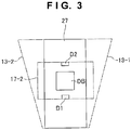
- Fig. 3 shows a layout example of the window 17-2 and side wall members 13-1 and 13-2.
- two corresponding adjacent side wall members for example, the side wall members 13-1 and 13-2
- the plurality of side wall members can more reliably prevent the plurality of light-emitting members (the plurality of internal light components) from interfering with each other.
- the light-emitting member 27 preferably includes, for example, two infrared light-emitting elements D1 and D2, and further includes a heat radiation plate DB.
- ON/OFF of the two infrared light-emitting elements D1 and D2 is controlled by, for example, a controller 21 (a logic board including a control circuit) shown in Fig. 2 .
- the controller 21 can also control light-emitting elements (not shown) forming the light-emitting members 28 and 29.
- Fig. 3 the side wall members 13-1 and 13-2 are laid out on the two sides of or at the back of the window 17-2. In other words, Fig. 3 does not show the windows 18-2 and 19-2.
- the lawn mower 50 recognizes the window 17-2 (the internal light), therefore, the influence (misrecognition) of the windows 18-2 and 19-2 (the internal light) can be avoided.
- the lawn mower 50 can more accurately recognize the marking device 10 based on the recognition of the window 17-2 (the internal light).
- the two infrared light-emitting elements D1 and D2 are positioned on the edges (the upper and lower sides) of the window 17-2. Accordingly, the window 17-2 can efficiently emit the internal light.
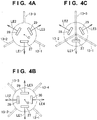
- Figs. 4A, 4B, and 4C are views for explaining the light (internal light) from the light-emitting unit 20.
- the light-emitting unit 20 forms omnidirectional light by, for example, three internal light components
- three light-emitting members 27, 28, and 29 shown in Fig. 4A can have optical axes LE1, LE2, and LE3 allocated at every 120° (an angle obtained by dividing 360° by 3).
- light-emitting members 27, 28, 29, and 30 shown in Fig. 4B can have optical axes LE1, LE2, LE3, and LE4 allocated at every 90° (an angle obtained by dividing 360° by 4).
- the light-emitting unit 20 can form omnidirectional light by, for example, four internal light components, the manufacturing cost of the marking device 10 capable of emitting omnidirectional light can be reduced.
- the number ⁇ (an integer of 2 or more) of the plurality of light-emitting members is preferably the same as the number ⁇ of the plurality of side wall members, and three or four, from the viewpoint of the manufacturing cost.
- the side wall members 13-1, 13-2, and 13-3 can extend outward from a central axis O of the circumferential portion of the housing 12 as an example (see Fig. 4C ).
- the quantity of each of the three internal light components increases by reflection in the circumferential portion of the housing 12. Accordingly, the lawn mower 50 can more accurately recognize the marking device 10 based on the recognition of, for example, the window 17-2 (the internal light enhanced by the side wall members 13-1 and 13-2 (blades) shown in Fig. 4C ).
- the side wall members 13-1, 13-2, 13-3, and 13-4 can extend outward from the central axis O of the circumferential portion of the housing 12 as an example.
- Fig. 5 shows a configuration example (functional block example) of the lawn mower 50.
- the lawn mower 50 includes a processing unit CPU, a storage unit MEMORY, a recognition unit CAMERA, a working unit BLADE, a power supply unit POWER, and an activation unit MOTOR.
- the processing unit CPU is typically a microcomputer.
- the storage unit MEMORY stores a program which causes the processing unit CPU to execute a predetermined operation or work.
- the storage unit MEMORY can form a work area of the processing unit CPU.
- the storage unit MEMORY can also store data necessary to execute an operation or work set in the processing unit CPU.
- the recognition unit CAMERA is typically a camera, and preferably an infrared camera.
- the working unit BLADE is typically a blade for a lawn mowing work.
- the power supply unit POWER is typically a chargeable battery.
- the activation unit MOTOR typically includes an electric motor and wheels. Even after sunset, for example, the lawn mower 50 including an infrared camera can automatically execute a lawn mowing work within a working range at night while automatically traveling within the working range.
- the lawn mower 50 can more accurately recognize light (internal light) evenly transmitted (emitted) from the transmitting portion (the light-emitting unit). In other words, the lawn mower 50 can more accurately recognize a remote marking device 10.
Landscapes
- Engineering & Computer Science (AREA)
- Physics & Mathematics (AREA)
- General Physics & Mathematics (AREA)
- Electromagnetism (AREA)
- Radar, Positioning & Navigation (AREA)
- Remote Sensing (AREA)
- General Engineering & Computer Science (AREA)
- Computer Networks & Wireless Communication (AREA)
- Environmental Sciences (AREA)
- Life Sciences & Earth Sciences (AREA)
- Aviation & Aerospace Engineering (AREA)
- Automation & Control Theory (AREA)
- Theoretical Computer Science (AREA)
- Harvester Elements (AREA)
- Control Of Position, Course, Altitude, Or Attitude Of Moving Bodies (AREA)
- Non-Portable Lighting Devices Or Systems Thereof (AREA)
Abstract
Description
- The present invention relates to a marking device (for example, a beacon) for a lawn mower (for example, an autonomous lawn mowing robot).
-
U.S. Patent Application Publication No. 2015/0271991 has disclosed a robot lawn mower 10 (an autonomous lawn mowing robot) as an example of a lawn mower. Therobot lawn mower 10 can recognize a lawn mowing range (working range) by recognizing a boundary marker 810 (a marking device) as a beacon. - For workers or those skilled in the art, the marking device is desirably easily recognizable by a lawn mower. In other words, it is preferable that a lawn mower does not recognize a marking device for defining a working range by mistake.
- One aspect of the present invention is to provide a marking device which a lawn mower can recognize more accurately. Other aspects of the present invention will become apparent to those skilled in the art by referring to the following exemplary embodiments, the best mode for carrying out the invention, and the attached drawings.
- The present invention provides a marking device for a lawn mower as specified in
claims 1 to 10. -
-
Fig. 1 is a view for explaining a working range defined by a plurality of marking devices; -
Fig. 2A shows a configuration example (outer appearance example) of the marking device; -
Figs. 2B and 2C show configuration examples (outer appearance examples) of a housing and a light-emitting unit; -
Fig. 3 shows a layout example of a window and side wall members; -
Figs. 4A to 4C are views for explaining light (internal light) from the light-emitting unit; and -
Fig. 5 is a view showing a configuration example (functional block example) of a lawn mower. - The best mode for carrying out the invention to be explained below is used to easily understand the present invention. Accordingly, those skilled in the art should note that the present invention is not unreasonably limited by the embodiments to be explained below.
-
Fig. 1 is a view for explaining a working range defined by a plurality of marking devices. InFig. 1 , the dotted lines indicate the working range within which alawn mower 50 can travel or move. In one example, this working range is defined by, for example, ten marking devices 10-1, 10-2,..., 10-9, and 10-10. In other words, thelawn mower 50 can execute a work such as lawn mowing within this working range. - Note that the lawn mower 50 (a travelable working machine 50) is typically an autonomous lawn mowing robot. For example, this autonomous lawn mowing robot can recognize at least one of (preferably, a plurality of) the ten marking devices 10-1, 10-2,..., 10-9, and 10-10, and can execute lawn mowing while traveling within the working range in which a lawn is planted.
- The working range is defined by the ten marking devices 10-1, 10-2,..., 10-9, and 10-10 in
Fig. 1 , but the working range of thelawn mower 50 may also be defined by at least three marking devices. In other words, it is also possible to arrange at least three marking devices at corners, and set the working range by these corners. The number (total number) of marking devices can, of course, be two or one, and thelawn mower 50 can estimate a predetermined working range by the two or one marking device. In other words, aworking system 100 includes thelawn mower 50 and at least one marking device. -
Fig. 2A shows a configuration example (outer appearance example) of themarking device 10.Figs. 2B and 2C respectively show configuration examples (outer appearance examples) of ahousing 12 and a light-emitting unit. Referring toFig. 2A , themarking device 10 is buried in or installed on a working ground as a lawn. In other words, a worker or user can stick themarking device 10 into the position of a lawn, which corresponds to a corner or the like of a working range, in order to define the working range of the lawn. - The
marking device 10 for thelawn mower 50 includes thehousing 12 accommodating a light-emittingunit 20 shown in, for example,Fig. 2C , and asupport 15 capable of supporting thehousing 12. The light-emittingunit 20 can emit light (internal light). Thehousing 12 includes a transmitting portion (for example, a plurality of windows 17-2, 18-2, and 19-2) for transmitting the light (internal light) through the circumferential portion of thehousing 12, and aroof 11 which covers the light-emitting unit 20 (for example, a plurality of light-emittingmembers housing 12. - As shown in
Fig. 2A , thehousing 12 accommodating the light-emittingunit 20 has theroof 11 for covering the light-emittingunit 20. When external light such as sunlight S1 irradiates themarking device 10, therefore, it is possible to prevent this external light from entering the light-emittingunit 20 or the transmitting portion such as the window 17-2. - If the
housing 12 of themarking device 10 has noroof 11, the sunlight S1 may be reflected by, for example, the window 17-2. In other words, if thehousing 12 of themarking device 10 has noroof 11, thelawn mower 50 may erroneously recognize the reflected light (sunlight S1) as the light-emitting unit 20 (the internal light) or the window 17-2. - In
Fig. 2A , thehousing 12 of themarking device 10 has theroof 11 capable of blocking the external light (sunlight S1) advancing to the light-emittingunit 20. Accordingly, thelawn mower 50 shown inFig. 1 can more accurately recognize each of the ten marking devices 10-1, 10-2,..., 10-9, and 10-10 shown inFig. 1 . - The
roof 11 is preferably a light-shielding portion capable of shielding the sunlight S1. Since the roof 11 (the light-shielding portion) can shield the sunlight S1 as external light, the sunlight S1 is absorbed or diminished by theroof 11. Therefore, thelawn mower 50 shown inFig. 1 can more accurately recognize each of the ten marking devices 10-1, 10-2,..., 10-9, and 10-10 shown inFig. 1 . - The transmitting portion includes the three windows 17-2, 18-2, and 19-2 in
Fig. 2B , and the light-emittingunit 20 includes the three light-emittingmembers Fig. 2C . Each of the plurality of windows 17-2, 18-2, and 19-2 (for example, the window 17-2) can transmit light from a corresponding one (for example, the light-emitting member 27) of the plurality of light-emittingmembers housing 12 includes a side wall (for example, a side wall member 13-2) formed between every two adjacent windows (for example, the windows 17-2 and 18-2) of the plurality of windows 17-2, 18-2, and 19-2. - In
Fig. 2C , the light-emittingunit 20 includes the plurality of light-emittingmembers marking device 10 can emit light in a plurality of directions. In other words, when thelawn mower 50 shown inFig. 1 travels or moves within the working range, thelawn mower 50 hardly misses each of the ten marking devices 10-1, 10-2,..., 10-9, and 10-10 shown inFig. 1 . - In
Fig. 2B , thehousing 12 includes the side wall (for example, side wall members 13-1, 13-2, and 13-3). Accordingly, the side wall members 13-1, 13-2, and 13-3 can prevent the plurality of light-emittingmembers - In addition, the side wall member 13-2, for example, can prevent external light S2 such as sunlight or a street light from entering the light-emitting
unit 20 or the transmitting portion such as the window 17-2 (seeFig. 2A ). Note that when the working ground is a lawn and the lawn contains water droplets (for example, rainwater), sunlight S3 is reflected by the lawn, but the side wall member 13-2, for example, can prevent the sunlight S3 as the reflected light from entering the light-emittingunit 20 or the transmitting portion such as the window 17-2 (seeFig. 2A ). - Preferably, the
housing 12 excluding the transmitting portion, in other words, the side wall such as the side wall member 13-2 and circumferential portions 17-1 and 17-3 of the transmitting portion can form a light-shielding portion. Since thehousing 12 excluding the transmitting portion (that is, theroof 11, the side wall, and the circumferential portions) can shield the external light components S1, S2, and S3, the external light components S1, S2, and S3 are absorbed or diminished by thehousing 12 excluding the transmitting portion. Therefore, thelawn mower 50 shown inFig. 1 can more accurately recognize each of the ten marking devices 10-1, 10-2,..., 10-9, and 10-10 shown inFig. 1 . - In
Fig. 2B , the side wall includes the three side wall members 13-1, 13-2, and 13-3. The plurality of side wall members 13-1, 13-2, and 13-3 are arranged at equal intervals on the circumferential portion of thehousing 12. The plurality of light-emittingmembers housing 12. - When the side wall includes the plurality of side wall members 13-1, 13-2, and 13-3, the plurality of side wall members 13-1, 13-2, and 13-3 can more reliably prevent the plurality of light-emitting
members housing 12, the light-emittingunit 20 can efficiently emit the plurality of internal light components. - In addition, when the light-emitting
unit 20 omnidirectionally emits the plurality of internal light components, thelawn mower 50 shown inFig. 1 more hardly misses each of the ten marking devices 10-1, 10-2,..., 10-9, and 10-10 shown inFig. 1 while traveling or moving within the working range. The number of the plurality of side wall members is three inFig. 2B , and the number of the plurality of light-emitting members is three inFig. 2C . For example, the three light-emittingmembers Fig. 4A ) allocated at every 120°. Since the light-emittingunit 20 can form omnidirectional light by the three internal light components, the manufacturing cost of the markingdevice 10 capable of emitting omnidirectional light can be reduced. -
Fig. 3 shows a layout example of the window 17-2 and side wall members 13-1 and 13-2. Referring toFig. 3 , for each of the plurality of windows (for example, the window 17-2 shown inFig. 3 ), two corresponding adjacent side wall members (for example, the side wall members 13-1 and 13-2) of the plurality of side wall members are laid out on the two sides of the corresponding window (for example, the window 17-2) of the plurality of windows in a front view. Since the two adjacent side wall members 13-1 and 13-2 are appropriately laid out on the two sides of the window 17-2, the plurality of side wall members (the side wall) can more reliably prevent the plurality of light-emitting members (the plurality of internal light components) from interfering with each other. - In
Fig. 3 , the light-emittingmember 27 preferably includes, for example, two infrared light-emitting elements D1 and D2, and further includes a heat radiation plate DB. Note that ON/OFF of the two infrared light-emitting elements D1 and D2 is controlled by, for example, a controller 21 (a logic board including a control circuit) shown inFig. 2 . Note also that thecontroller 21 can also control light-emitting elements (not shown) forming the light-emittingmembers - In
Fig. 3 , the side wall members 13-1 and 13-2 are laid out on the two sides of or at the back of the window 17-2. In other words,Fig. 3 does not show the windows 18-2 and 19-2. When thelawn mower 50 recognizes the window 17-2 (the internal light), therefore, the influence (misrecognition) of the windows 18-2 and 19-2 (the internal light) can be avoided. Thus, thelawn mower 50 can more accurately recognize the markingdevice 10 based on the recognition of the window 17-2 (the internal light). - Note that in
Fig. 3 , the two infrared light-emitting elements D1 and D2 are positioned on the edges (the upper and lower sides) of the window 17-2. Accordingly, the window 17-2 can efficiently emit the internal light. -
Figs. 4A, 4B, and 4C are views for explaining the light (internal light) from the light-emittingunit 20. When the light-emittingunit 20 forms omnidirectional light by, for example, three internal light components, three light-emittingmembers Fig. 4A can have optical axes LE1, LE2, and LE3 allocated at every 120° (an angle obtained by dividing 360° by 3). Alternatively, when the light-emittingunit 20 forms omnidirectional light by, for example, four internal light components, light-emittingmembers Fig. 4B can have optical axes LE1, LE2, LE3, and LE4 allocated at every 90° (an angle obtained by dividing 360° by 4). Since the light-emittingunit 20 can form omnidirectional light by, for example, four internal light components, the manufacturing cost of the markingdevice 10 capable of emitting omnidirectional light can be reduced. In other words, the number α (an integer of 2 or more) of the plurality of light-emitting members is preferably the same as the number α of the plurality of side wall members, and three or four, from the viewpoint of the manufacturing cost. - When the light-emitting
unit 20 forms omnidirectional light by, for example, three internal light components, the side wall members 13-1, 13-2, and 13-3 can extend outward from a central axis O of the circumferential portion of thehousing 12 as an example (seeFig. 4C ). InFig. 4C , the quantity of each of the three internal light components increases by reflection in the circumferential portion of thehousing 12. Accordingly, thelawn mower 50 can more accurately recognize the markingdevice 10 based on the recognition of, for example, the window 17-2 (the internal light enhanced by the side wall members 13-1 and 13-2 (blades) shown inFig. 4C ). - When the light-emitting
unit 20 forms omnidirectional light by, for example, four internal light components as shown inFig. 4C when modifying or improvingFig. 4B , the side wall members 13-1, 13-2, 13-3, and 13-4 (blades) can extend outward from the central axis O of the circumferential portion of thehousing 12 as an example. -
Fig. 5 shows a configuration example (functional block example) of thelawn mower 50. As an example, thelawn mower 50 includes a processing unit CPU, a storage unit MEMORY, a recognition unit CAMERA, a working unit BLADE, a power supply unit POWER, and an activation unit MOTOR. The processing unit CPU is typically a microcomputer. The storage unit MEMORY stores a program which causes the processing unit CPU to execute a predetermined operation or work. The storage unit MEMORY can form a work area of the processing unit CPU. The storage unit MEMORY can also store data necessary to execute an operation or work set in the processing unit CPU. - The recognition unit CAMERA is typically a camera, and preferably an infrared camera. The working unit BLADE is typically a blade for a lawn mowing work. The power supply unit POWER is typically a chargeable battery. The activation unit MOTOR typically includes an electric motor and wheels. Even after sunset, for example, the
lawn mower 50 including an infrared camera can automatically execute a lawn mowing work within a working range at night while automatically traveling within the working range. - For example, when the transmitting portion such as the window 17-2 shown in
Fig. 2A contains a light diffuser, thelawn mower 50 can more accurately recognize light (internal light) evenly transmitted (emitted) from the transmitting portion (the light-emitting unit). In other words, thelawn mower 50 can more accurately recognize aremote marking device 10. - The present invention is not limited to the above-described exemplary embodiments, and those skilled in the art can easily change the above-described exemplary embodiments to a range contained in the scope of claims.
Claims (10)
- A marking device (10) for a lawn mower (50), comprising:a light-emitting unit (20) configured to emit light;a housing (12) configured to accommodate the light-emitting unit (20); anda support (15) configured to support the housing (12),wherein the housing (12) includes:a transmitting portion (17-2; 18-2; 19-2) configured to transmit the light through a circumferential portion of the housing (12); anda roof (11) covering the light-emitting unit (20) accommodated in the housing (12),the transmitting portion (17-2; 18-2; 19-2) includes a plurality of windows, andthe housing (12) includes a side wall (13-1; 13-2; 13-3; 13-4) formed between every two adjacent windows of the plurality of windows.
- The device according to claim 1, wherein
the light-emitting unit includes a plurality of light-emitting members, and
each of the plurality of windows is configured to transmit light from a corresponding one of the plurality of light-emitting members. - The device according to claim 2, wherein
the side wall includes a plurality of side wall members,
the plurality of side wall members are arranged at equal intervals on the circumferential portion of the housing, and
the plurality of light-emitting members are configured to omnidirectionally emit the light from the circumferential portion of the housing. - The device according to claim 2, wherein
the number of the plurality of side wall members is α (an integer of not less than 2),
the number of the plurality of light-emitting members is α, and
the plurality of light-emitting members have optical axes allocated for every angle obtained by dividing 360° by α. - The device according to claim 3, wherein
the number of the plurality of side wall members is 3,
the number of the plurality of light-emitting members is 3, and
the plurality of light-emitting members have optical axes allocated for every 120°. - The device according to claim 3, wherein
the number of the plurality of side wall members is 4,
the number of the plurality of light-emitting members is 4, and
the plurality of light-emitting members have optical axes allocated for every 90°. - The device according to any one of claims 1 to 6, wherein for each of the plurality of windows, two corresponding adjacent side wall members of the plurality of side wall members are arranged on two sides of the window in a front view.
- The device according to any one of claims 1 to 6, wherein the roof comprises a light-shielding portion configured to shield sunlight.
- The device according to claim 8, wherein the housing excluding the transmitting portion forms the light-shielding portion.
- The device according to any one of claims 1 to 6, wherein the transmitting portion contains a light diffuser.
Applications Claiming Priority (1)
| Application Number | Priority Date | Filing Date | Title |
|---|---|---|---|
| JP2016071846A JP6635850B2 (en) | 2016-03-31 | 2016-03-31 | Sign device for lawn mower |
Publications (2)
| Publication Number | Publication Date |
|---|---|
| EP3226019A1 true EP3226019A1 (en) | 2017-10-04 |
| EP3226019B1 EP3226019B1 (en) | 2021-07-28 |
Family
ID=58461178
Family Applications (1)
| Application Number | Title | Priority Date | Filing Date |
|---|---|---|---|
| EP17163834.9A Active EP3226019B1 (en) | 2016-03-31 | 2017-03-30 | Marking device for lawn mower |
Country Status (4)
| Country | Link |
|---|---|
| US (1) | US10094533B2 (en) |
| EP (1) | EP3226019B1 (en) |
| JP (1) | JP6635850B2 (en) |
| CN (1) | CN107274807A (en) |
Cited By (1)
| Publication number | Priority date | Publication date | Assignee | Title |
|---|---|---|---|---|
| EP3769598A4 (en) * | 2018-03-23 | 2021-03-31 | Honda Motor Co., Ltd. | INVESTMENT POSITION NOTIFICATION SYSTEM |
Families Citing this family (2)
| Publication number | Priority date | Publication date | Assignee | Title |
|---|---|---|---|---|
| USD828603S1 (en) * | 2017-06-13 | 2018-09-11 | A9.Com, Inc. | Path light |
| CN113339735A (en) * | 2021-05-25 | 2021-09-03 | 仙居县天顶林业有限公司 | LED projection lamp |
Citations (4)
| Publication number | Priority date | Publication date | Assignee | Title |
|---|---|---|---|---|
| WO2005093537A1 (en) * | 2004-03-22 | 2005-10-06 | BSH Bosch und Siemens Hausgeräte GmbH | Surface treating system |
| DE102007036220A1 (en) * | 2007-08-02 | 2009-02-05 | BSH Bosch und Siemens Hausgeräte GmbH | Light signal radiating device for determining position and defining guideway of self-propelled accumulator-controlled dust collecting robot, has light emitting elements received by receiving openings of carrier part |
| WO2012085851A1 (en) * | 2010-12-22 | 2012-06-28 | Koninklijke Philips Electronics N.V. | Vehicle positioning and guidance system |
| US20150271991A1 (en) | 2014-03-31 | 2015-10-01 | Irobot Corporation | Autonomous Mobile Robot |
Family Cites Families (19)
| Publication number | Priority date | Publication date | Assignee | Title |
|---|---|---|---|---|
| JPS58175017A (en) * | 1982-04-07 | 1983-10-14 | Kubota Ltd | Automatic guiding device for running vehicle |
| US4527158A (en) * | 1982-07-29 | 1985-07-02 | Runnels Russell W | Aircraft collision pilot warning indicating system |
| US5367442A (en) * | 1989-08-11 | 1994-11-22 | Siemens Solar Industries L.P. | Self-contained solar powered lamp |
| US4999060A (en) * | 1989-08-11 | 1991-03-12 | Siemens Solar Industries, L.P. | Solar cell packaging assembly for self-contained light |
| US5155666A (en) * | 1990-12-21 | 1992-10-13 | Eg&G, Inc. | Light beacon for marking tall obstructions |
| JP2600517Y2 (en) * | 1993-10-19 | 1999-10-12 | 株式会社小糸製作所 | Sign light |
| ITTO980216A1 (en) * | 1998-03-13 | 1998-06-13 | Giuseppe Morfino | LIGHTING DEVICE AND LIGHTING SYSTEM USING THIS DEVICE. |
| JP2000087321A (en) * | 1998-09-15 | 2000-03-28 | Aiee Komu Kk | Sign board for boundary pile |
| US6017131A (en) * | 1998-10-15 | 2000-01-25 | Goins; Marilyn D. | Illuminated mail box post |
| JP3427187B2 (en) * | 2001-02-07 | 2003-07-14 | 東京大学長 | Distance measuring apparatus and measuring method using modulated light |
| JP4397952B2 (en) * | 2008-02-12 | 2010-01-13 | きらり機械設計有限会社 | Moving object arrangement measuring system and moving object mounting system |
| FR2930496B1 (en) * | 2008-04-28 | 2010-04-30 | Mercura | WARNING AND SIGNALING LAMP |
| CN201696925U (en) * | 2010-05-27 | 2011-01-05 | 江苏史福特光电科技有限公司 | LED lamp bulb |
| US8292452B2 (en) * | 2010-06-07 | 2012-10-23 | Ko Joseph Y | Solar power alarm lamp |
| DE102011007214B4 (en) * | 2011-04-12 | 2013-08-14 | Osram Gmbh | Piston for semiconductor light-emitting device and semiconductor light-emitting device |
| CN104040251B (en) * | 2011-12-27 | 2018-11-13 | 飞利浦照明控股有限公司 | Reflector arrangement and the lighting device for including this reflector arrangement |
| JP5798070B2 (en) * | 2012-03-22 | 2015-10-21 | 株式会社サンコーシヤ | Aviation Obstruction Light |
| CN106062469A (en) * | 2014-02-19 | 2016-10-26 | 飞利浦灯具控股公司 | Luminaire and lighting arrangement |
| US9375842B2 (en) * | 2014-05-15 | 2016-06-28 | Irobot Corporation | Autonomous mobile robot confinement system |
-
2016
- 2016-03-31 JP JP2016071846A patent/JP6635850B2/en not_active Expired - Fee Related
-
2017
- 2017-03-28 CN CN201710192462.1A patent/CN107274807A/en active Pending
- 2017-03-29 US US15/473,169 patent/US10094533B2/en active Active
- 2017-03-30 EP EP17163834.9A patent/EP3226019B1/en active Active
Patent Citations (4)
| Publication number | Priority date | Publication date | Assignee | Title |
|---|---|---|---|---|
| WO2005093537A1 (en) * | 2004-03-22 | 2005-10-06 | BSH Bosch und Siemens Hausgeräte GmbH | Surface treating system |
| DE102007036220A1 (en) * | 2007-08-02 | 2009-02-05 | BSH Bosch und Siemens Hausgeräte GmbH | Light signal radiating device for determining position and defining guideway of self-propelled accumulator-controlled dust collecting robot, has light emitting elements received by receiving openings of carrier part |
| WO2012085851A1 (en) * | 2010-12-22 | 2012-06-28 | Koninklijke Philips Electronics N.V. | Vehicle positioning and guidance system |
| US20150271991A1 (en) | 2014-03-31 | 2015-10-01 | Irobot Corporation | Autonomous Mobile Robot |
Cited By (1)
| Publication number | Priority date | Publication date | Assignee | Title |
|---|---|---|---|---|
| EP3769598A4 (en) * | 2018-03-23 | 2021-03-31 | Honda Motor Co., Ltd. | INVESTMENT POSITION NOTIFICATION SYSTEM |
Also Published As
| Publication number | Publication date |
|---|---|
| JP2017181408A (en) | 2017-10-05 |
| JP6635850B2 (en) | 2020-01-29 |
| US20170284625A1 (en) | 2017-10-05 |
| US10094533B2 (en) | 2018-10-09 |
| EP3226019B1 (en) | 2021-07-28 |
| CN107274807A (en) | 2017-10-20 |
Similar Documents
| Publication | Publication Date | Title |
|---|---|---|
| US11715072B2 (en) | System, devices and methods for tele-operated robotics | |
| EP3226019B1 (en) | Marking device for lawn mower | |
| EP3366100B1 (en) | Robotic garden tool | |
| KR101334960B1 (en) | Lawn mower robot system and control method for the same | |
| CN104722934B (en) | Laser machine device | |
| EP3237984B1 (en) | Area exclusion for operation of a robotic vehicle | |
| US10328530B2 (en) | Flexible and local laser shroud | |
| KR101906140B1 (en) | Flight operating system for controlling unmanned drone | |
| ES2911626T3 (en) | Mobile power supply device for outdoor power supply | |
| KR101280365B1 (en) | Lawn mower robot system and control method for the same | |
| JP2021504209A (en) | Agricultural drone | |
| CN105629972B (en) | Guiding virtual wall system | |
| CN117561868A (en) | Mobile devices, functional modules and automatic working systems | |
| US20190195472A1 (en) | Systems and methods for a ladder with integrated lights | |
| JP2017091246A (en) | Reaping robot and automatic reaping system using the same | |
| CN111552295A (en) | Control method and device of unmanned bird repelling vehicle and autonomous bird repelling system | |
| AU2020300962A1 (en) | System, devices and methods for tele-operated robotics | |
| EP3300842B1 (en) | System and method for coordinating terrestrial mobile automated devices | |
| CN112889011A (en) | Electronic communication device for use in a navigation system | |
| US20230205211A1 (en) | Protection of ultraviolet (uv) light source on mobile device | |
| CN102565757A (en) | Accurate-positioning navigation system of autonomous mobile device | |
| CN205179743U (en) | Automatic mowing system | |
| KR102648850B1 (en) | Pattern lighting apparatus for generating robot-recognizable pattern and building including the same | |
| KR20210155557A (en) | Controlling method of System comprising Lawn mower robot | |
| JP2017181408A5 (en) |
Legal Events
| Date | Code | Title | Description |
|---|---|---|---|
| PUAI | Public reference made under article 153(3) epc to a published international application that has entered the european phase |
Free format text: ORIGINAL CODE: 0009012 |
|
| STAA | Information on the status of an ep patent application or granted ep patent |
Free format text: STATUS: REQUEST FOR EXAMINATION WAS MADE |
|
| 17P | Request for examination filed |
Effective date: 20170330 |
|
| AK | Designated contracting states |
Kind code of ref document: A1 Designated state(s): AL AT BE BG CH CY CZ DE DK EE ES FI FR GB GR HR HU IE IS IT LI LT LU LV MC MK MT NL NO PL PT RO RS SE SI SK SM TR |
|
| AX | Request for extension of the european patent |
Extension state: BA ME |
|
| STAA | Information on the status of an ep patent application or granted ep patent |
Free format text: STATUS: EXAMINATION IS IN PROGRESS |
|
| 17Q | First examination report despatched |
Effective date: 20181207 |
|
| GRAP | Despatch of communication of intention to grant a patent |
Free format text: ORIGINAL CODE: EPIDOSNIGR1 |
|
| STAA | Information on the status of an ep patent application or granted ep patent |
Free format text: STATUS: GRANT OF PATENT IS INTENDED |
|
| RIC1 | Information provided on ipc code assigned before grant |
Ipc: G05D 1/02 20200101ALI20210205BHEP Ipc: A01D 34/00 20060101ALI20210205BHEP Ipc: G01S 1/70 20060101AFI20210205BHEP |
|
| INTG | Intention to grant announced |
Effective date: 20210303 |
|
| GRAS | Grant fee paid |
Free format text: ORIGINAL CODE: EPIDOSNIGR3 |
|
| GRAA | (expected) grant |
Free format text: ORIGINAL CODE: 0009210 |
|
| STAA | Information on the status of an ep patent application or granted ep patent |
Free format text: STATUS: THE PATENT HAS BEEN GRANTED |
|
| AK | Designated contracting states |
Kind code of ref document: B1 Designated state(s): AL AT BE BG CH CY CZ DE DK EE ES FI FR GB GR HR HU IE IS IT LI LT LU LV MC MK MT NL NO PL PT RO RS SE SI SK SM TR |
|
| REG | Reference to a national code |
Ref country code: GB Ref legal event code: FG4D |
|
| REG | Reference to a national code |
Ref country code: CH Ref legal event code: EP |
|
| REG | Reference to a national code |
Ref country code: AT Ref legal event code: REF Ref document number: 1415184 Country of ref document: AT Kind code of ref document: T Effective date: 20210815 |
|
| REG | Reference to a national code |
Ref country code: IE Ref legal event code: FG4D |
|
| REG | Reference to a national code |
Ref country code: DE Ref legal event code: R096 Ref document number: 602017042774 Country of ref document: DE |
|
| REG | Reference to a national code |
Ref country code: LT Ref legal event code: MG9D |
|
| REG | Reference to a national code |
Ref country code: NL Ref legal event code: MP Effective date: 20210728 |
|
| REG | Reference to a national code |
Ref country code: AT Ref legal event code: MK05 Ref document number: 1415184 Country of ref document: AT Kind code of ref document: T Effective date: 20210728 |
|
| PG25 | Lapsed in a contracting state [announced via postgrant information from national office to epo] |
Ref country code: RS Free format text: LAPSE BECAUSE OF FAILURE TO SUBMIT A TRANSLATION OF THE DESCRIPTION OR TO PAY THE FEE WITHIN THE PRESCRIBED TIME-LIMIT Effective date: 20210728 Ref country code: SE Free format text: LAPSE BECAUSE OF FAILURE TO SUBMIT A TRANSLATION OF THE DESCRIPTION OR TO PAY THE FEE WITHIN THE PRESCRIBED TIME-LIMIT Effective date: 20210728 Ref country code: NL Free format text: LAPSE BECAUSE OF FAILURE TO SUBMIT A TRANSLATION OF THE DESCRIPTION OR TO PAY THE FEE WITHIN THE PRESCRIBED TIME-LIMIT Effective date: 20210728 Ref country code: PT Free format text: LAPSE BECAUSE OF FAILURE TO SUBMIT A TRANSLATION OF THE DESCRIPTION OR TO PAY THE FEE WITHIN THE PRESCRIBED TIME-LIMIT Effective date: 20211129 Ref country code: NO Free format text: LAPSE BECAUSE OF FAILURE TO SUBMIT A TRANSLATION OF THE DESCRIPTION OR TO PAY THE FEE WITHIN THE PRESCRIBED TIME-LIMIT Effective date: 20211028 Ref country code: HR Free format text: LAPSE BECAUSE OF FAILURE TO SUBMIT A TRANSLATION OF THE DESCRIPTION OR TO PAY THE FEE WITHIN THE PRESCRIBED TIME-LIMIT Effective date: 20210728 Ref country code: FI Free format text: LAPSE BECAUSE OF FAILURE TO SUBMIT A TRANSLATION OF THE DESCRIPTION OR TO PAY THE FEE WITHIN THE PRESCRIBED TIME-LIMIT Effective date: 20210728 Ref country code: ES Free format text: LAPSE BECAUSE OF FAILURE TO SUBMIT A TRANSLATION OF THE DESCRIPTION OR TO PAY THE FEE WITHIN THE PRESCRIBED TIME-LIMIT Effective date: 20210728 Ref country code: BG Free format text: LAPSE BECAUSE OF FAILURE TO SUBMIT A TRANSLATION OF THE DESCRIPTION OR TO PAY THE FEE WITHIN THE PRESCRIBED TIME-LIMIT Effective date: 20211028 Ref country code: AT Free format text: LAPSE BECAUSE OF FAILURE TO SUBMIT A TRANSLATION OF THE DESCRIPTION OR TO PAY THE FEE WITHIN THE PRESCRIBED TIME-LIMIT Effective date: 20210728 Ref country code: LT Free format text: LAPSE BECAUSE OF FAILURE TO SUBMIT A TRANSLATION OF THE DESCRIPTION OR TO PAY THE FEE WITHIN THE PRESCRIBED TIME-LIMIT Effective date: 20210728 |
|
| PG25 | Lapsed in a contracting state [announced via postgrant information from national office to epo] |
Ref country code: PL Free format text: LAPSE BECAUSE OF FAILURE TO SUBMIT A TRANSLATION OF THE DESCRIPTION OR TO PAY THE FEE WITHIN THE PRESCRIBED TIME-LIMIT Effective date: 20210728 Ref country code: LV Free format text: LAPSE BECAUSE OF FAILURE TO SUBMIT A TRANSLATION OF THE DESCRIPTION OR TO PAY THE FEE WITHIN THE PRESCRIBED TIME-LIMIT Effective date: 20210728 Ref country code: GR Free format text: LAPSE BECAUSE OF FAILURE TO SUBMIT A TRANSLATION OF THE DESCRIPTION OR TO PAY THE FEE WITHIN THE PRESCRIBED TIME-LIMIT Effective date: 20211029 |
|
| PG25 | Lapsed in a contracting state [announced via postgrant information from national office to epo] |
Ref country code: DK Free format text: LAPSE BECAUSE OF FAILURE TO SUBMIT A TRANSLATION OF THE DESCRIPTION OR TO PAY THE FEE WITHIN THE PRESCRIBED TIME-LIMIT Effective date: 20210728 |
|
| REG | Reference to a national code |
Ref country code: DE Ref legal event code: R097 Ref document number: 602017042774 Country of ref document: DE |
|
| PG25 | Lapsed in a contracting state [announced via postgrant information from national office to epo] |
Ref country code: SM Free format text: LAPSE BECAUSE OF FAILURE TO SUBMIT A TRANSLATION OF THE DESCRIPTION OR TO PAY THE FEE WITHIN THE PRESCRIBED TIME-LIMIT Effective date: 20210728 Ref country code: SK Free format text: LAPSE BECAUSE OF FAILURE TO SUBMIT A TRANSLATION OF THE DESCRIPTION OR TO PAY THE FEE WITHIN THE PRESCRIBED TIME-LIMIT Effective date: 20210728 Ref country code: RO Free format text: LAPSE BECAUSE OF FAILURE TO SUBMIT A TRANSLATION OF THE DESCRIPTION OR TO PAY THE FEE WITHIN THE PRESCRIBED TIME-LIMIT Effective date: 20210728 Ref country code: EE Free format text: LAPSE BECAUSE OF FAILURE TO SUBMIT A TRANSLATION OF THE DESCRIPTION OR TO PAY THE FEE WITHIN THE PRESCRIBED TIME-LIMIT Effective date: 20210728 Ref country code: CZ Free format text: LAPSE BECAUSE OF FAILURE TO SUBMIT A TRANSLATION OF THE DESCRIPTION OR TO PAY THE FEE WITHIN THE PRESCRIBED TIME-LIMIT Effective date: 20210728 Ref country code: AL Free format text: LAPSE BECAUSE OF FAILURE TO SUBMIT A TRANSLATION OF THE DESCRIPTION OR TO PAY THE FEE WITHIN THE PRESCRIBED TIME-LIMIT Effective date: 20210728 |
|
| PLBE | No opposition filed within time limit |
Free format text: ORIGINAL CODE: 0009261 |
|
| STAA | Information on the status of an ep patent application or granted ep patent |
Free format text: STATUS: NO OPPOSITION FILED WITHIN TIME LIMIT |
|
| 26N | No opposition filed |
Effective date: 20220429 |
|
| PG25 | Lapsed in a contracting state [announced via postgrant information from national office to epo] |
Ref country code: IT Free format text: LAPSE BECAUSE OF FAILURE TO SUBMIT A TRANSLATION OF THE DESCRIPTION OR TO PAY THE FEE WITHIN THE PRESCRIBED TIME-LIMIT Effective date: 20210728 |
|
| PG25 | Lapsed in a contracting state [announced via postgrant information from national office to epo] |
Ref country code: MC Free format text: LAPSE BECAUSE OF FAILURE TO SUBMIT A TRANSLATION OF THE DESCRIPTION OR TO PAY THE FEE WITHIN THE PRESCRIBED TIME-LIMIT Effective date: 20210728 |
|
| REG | Reference to a national code |
Ref country code: CH Ref legal event code: PL |
|
| GBPC | Gb: european patent ceased through non-payment of renewal fee |
Effective date: 20220330 |
|
| REG | Reference to a national code |
Ref country code: BE Ref legal event code: MM Effective date: 20220331 |
|
| PG25 | Lapsed in a contracting state [announced via postgrant information from national office to epo] |
Ref country code: LU Free format text: LAPSE BECAUSE OF NON-PAYMENT OF DUE FEES Effective date: 20220330 Ref country code: LI Free format text: LAPSE BECAUSE OF NON-PAYMENT OF DUE FEES Effective date: 20220331 Ref country code: IE Free format text: LAPSE BECAUSE OF NON-PAYMENT OF DUE FEES Effective date: 20220330 Ref country code: GB Free format text: LAPSE BECAUSE OF NON-PAYMENT OF DUE FEES Effective date: 20220330 Ref country code: FR Free format text: LAPSE BECAUSE OF NON-PAYMENT OF DUE FEES Effective date: 20220331 Ref country code: CH Free format text: LAPSE BECAUSE OF NON-PAYMENT OF DUE FEES Effective date: 20220331 |
|
| PG25 | Lapsed in a contracting state [announced via postgrant information from national office to epo] |
Ref country code: BE Free format text: LAPSE BECAUSE OF NON-PAYMENT OF DUE FEES Effective date: 20220331 |
|
| PG25 | Lapsed in a contracting state [announced via postgrant information from national office to epo] |
Ref country code: HU Free format text: LAPSE BECAUSE OF FAILURE TO SUBMIT A TRANSLATION OF THE DESCRIPTION OR TO PAY THE FEE WITHIN THE PRESCRIBED TIME-LIMIT; INVALID AB INITIO Effective date: 20170330 |
|
| PG25 | Lapsed in a contracting state [announced via postgrant information from national office to epo] |
Ref country code: MK Free format text: LAPSE BECAUSE OF FAILURE TO SUBMIT A TRANSLATION OF THE DESCRIPTION OR TO PAY THE FEE WITHIN THE PRESCRIBED TIME-LIMIT Effective date: 20210728 Ref country code: CY Free format text: LAPSE BECAUSE OF FAILURE TO SUBMIT A TRANSLATION OF THE DESCRIPTION OR TO PAY THE FEE WITHIN THE PRESCRIBED TIME-LIMIT Effective date: 20210728 |
|
| PG25 | Lapsed in a contracting state [announced via postgrant information from national office to epo] |
Ref country code: TR Free format text: LAPSE BECAUSE OF FAILURE TO SUBMIT A TRANSLATION OF THE DESCRIPTION OR TO PAY THE FEE WITHIN THE PRESCRIBED TIME-LIMIT Effective date: 20210728 |
|
| PG25 | Lapsed in a contracting state [announced via postgrant information from national office to epo] |
Ref country code: MT Free format text: LAPSE BECAUSE OF FAILURE TO SUBMIT A TRANSLATION OF THE DESCRIPTION OR TO PAY THE FEE WITHIN THE PRESCRIBED TIME-LIMIT Effective date: 20210728 |
|
| REG | Reference to a national code |
Ref country code: DE Ref legal event code: R081 Ref document number: 602017042774 Country of ref document: DE Owner name: HONDA MOTOR CO., LTD., JP Free format text: FORMER OWNERS: HONDA MOTOR CO., LTD., TOKYO, JP; ZMP INC., TOKYO, JP |
|
| PGFP | Annual fee paid to national office [announced via postgrant information from national office to epo] |
Ref country code: DE Payment date: 20260219 Year of fee payment: 10 |