EP3225926B1 - Evaporation heat exchange device for air cooling for conditioning and climate control systems for server rooms and the like - Google Patents
Evaporation heat exchange device for air cooling for conditioning and climate control systems for server rooms and the like Download PDFInfo
- Publication number
- EP3225926B1 EP3225926B1 EP17163764.8A EP17163764A EP3225926B1 EP 3225926 B1 EP3225926 B1 EP 3225926B1 EP 17163764 A EP17163764 A EP 17163764A EP 3225926 B1 EP3225926 B1 EP 3225926B1
- Authority
- EP
- European Patent Office
- Prior art keywords
- nozzles
- row
- water
- air
- heat exchanger
- Prior art date
- Legal status (The legal status is an assumption and is not a legal conclusion. Google has not performed a legal analysis and makes no representation as to the accuracy of the status listed.)
- Active
Links
- 238000001816 cooling Methods 0.000 title claims description 23
- 230000003750 conditioning effect Effects 0.000 title claims description 21
- 238000001704 evaporation Methods 0.000 title description 14
- 230000008020 evaporation Effects 0.000 title description 14
- XLYOFNOQVPJJNP-UHFFFAOYSA-N water Substances O XLYOFNOQVPJJNP-UHFFFAOYSA-N 0.000 claims description 39
- 239000000498 cooling water Substances 0.000 claims description 5
- 230000007423 decrease Effects 0.000 claims description 5
- 239000003570 air Substances 0.000 description 36
- 230000000670 limiting effect Effects 0.000 description 5
- 238000000034 method Methods 0.000 description 4
- 238000005265 energy consumption Methods 0.000 description 2
- 238000010521 absorption reaction Methods 0.000 description 1
- 238000004378 air conditioning Methods 0.000 description 1
- 239000012080 ambient air Substances 0.000 description 1
- 230000000694 effects Effects 0.000 description 1
- 230000005611 electricity Effects 0.000 description 1
- 239000000463 material Substances 0.000 description 1
- 238000012986 modification Methods 0.000 description 1
- 230000004048 modification Effects 0.000 description 1
- 238000005507 spraying Methods 0.000 description 1
Images


Classifications
-
- H—ELECTRICITY
- H05—ELECTRIC TECHNIQUES NOT OTHERWISE PROVIDED FOR
- H05K—PRINTED CIRCUITS; CASINGS OR CONSTRUCTIONAL DETAILS OF ELECTRIC APPARATUS; MANUFACTURE OF ASSEMBLAGES OF ELECTRICAL COMPONENTS
- H05K7/00—Constructional details common to different types of electric apparatus
- H05K7/20—Modifications to facilitate cooling, ventilating, or heating
- H05K7/20709—Modifications to facilitate cooling, ventilating, or heating for server racks or cabinets; for data centers, e.g. 19-inch computer racks
- H05K7/20836—Thermal management, e.g. server temperature control
-
- F—MECHANICAL ENGINEERING; LIGHTING; HEATING; WEAPONS; BLASTING
- F24—HEATING; RANGES; VENTILATING
- F24F—AIR-CONDITIONING; AIR-HUMIDIFICATION; VENTILATION; USE OF AIR CURRENTS FOR SCREENING
- F24F12/00—Use of energy recovery systems in air conditioning, ventilation or screening
- F24F12/001—Use of energy recovery systems in air conditioning, ventilation or screening with heat-exchange between supplied and exhausted air
- F24F12/006—Use of energy recovery systems in air conditioning, ventilation or screening with heat-exchange between supplied and exhausted air using an air-to-air heat exchanger
-
- F—MECHANICAL ENGINEERING; LIGHTING; HEATING; WEAPONS; BLASTING
- F24—HEATING; RANGES; VENTILATING
- F24F—AIR-CONDITIONING; AIR-HUMIDIFICATION; VENTILATION; USE OF AIR CURRENTS FOR SCREENING
- F24F5/00—Air-conditioning systems or apparatus not covered by F24F1/00 or F24F3/00, e.g. using solar heat or combined with household units such as an oven or water heater
- F24F5/0007—Air-conditioning systems or apparatus not covered by F24F1/00 or F24F3/00, e.g. using solar heat or combined with household units such as an oven or water heater cooling apparatus specially adapted for use in air-conditioning
- F24F5/0035—Air-conditioning systems or apparatus not covered by F24F1/00 or F24F3/00, e.g. using solar heat or combined with household units such as an oven or water heater cooling apparatus specially adapted for use in air-conditioning using evaporation
-
- H—ELECTRICITY
- H05—ELECTRIC TECHNIQUES NOT OTHERWISE PROVIDED FOR
- H05K—PRINTED CIRCUITS; CASINGS OR CONSTRUCTIONAL DETAILS OF ELECTRIC APPARATUS; MANUFACTURE OF ASSEMBLAGES OF ELECTRICAL COMPONENTS
- H05K7/00—Constructional details common to different types of electric apparatus
- H05K7/20—Modifications to facilitate cooling, ventilating, or heating
- H05K7/2029—Modifications to facilitate cooling, ventilating, or heating using a liquid coolant with phase change in electronic enclosures
- H05K7/20327—Accessories for moving fluid, for connecting fluid conduits, for distributing fluid or for preventing leakage, e.g. pumps, tanks or manifolds
-
- H—ELECTRICITY
- H05—ELECTRIC TECHNIQUES NOT OTHERWISE PROVIDED FOR
- H05K—PRINTED CIRCUITS; CASINGS OR CONSTRUCTIONAL DETAILS OF ELECTRIC APPARATUS; MANUFACTURE OF ASSEMBLAGES OF ELECTRICAL COMPONENTS
- H05K7/00—Constructional details common to different types of electric apparatus
- H05K7/20—Modifications to facilitate cooling, ventilating, or heating
- H05K7/2029—Modifications to facilitate cooling, ventilating, or heating using a liquid coolant with phase change in electronic enclosures
- H05K7/20345—Sprayers; Atomizers
-
- H—ELECTRICITY
- H05—ELECTRIC TECHNIQUES NOT OTHERWISE PROVIDED FOR
- H05K—PRINTED CIRCUITS; CASINGS OR CONSTRUCTIONAL DETAILS OF ELECTRIC APPARATUS; MANUFACTURE OF ASSEMBLAGES OF ELECTRICAL COMPONENTS
- H05K7/00—Constructional details common to different types of electric apparatus
- H05K7/20—Modifications to facilitate cooling, ventilating, or heating
- H05K7/20709—Modifications to facilitate cooling, ventilating, or heating for server racks or cabinets; for data centers, e.g. 19-inch computer racks
- H05K7/20718—Forced ventilation of a gaseous coolant
- H05K7/20745—Forced ventilation of a gaseous coolant within rooms for removing heat from cabinets, e.g. by air conditioning device
-
- H—ELECTRICITY
- H05—ELECTRIC TECHNIQUES NOT OTHERWISE PROVIDED FOR
- H05K—PRINTED CIRCUITS; CASINGS OR CONSTRUCTIONAL DETAILS OF ELECTRIC APPARATUS; MANUFACTURE OF ASSEMBLAGES OF ELECTRICAL COMPONENTS
- H05K7/00—Constructional details common to different types of electric apparatus
- H05K7/20—Modifications to facilitate cooling, ventilating, or heating
- H05K7/20709—Modifications to facilitate cooling, ventilating, or heating for server racks or cabinets; for data centers, e.g. 19-inch computer racks
- H05K7/208—Liquid cooling with phase change
- H05K7/20827—Liquid cooling with phase change within rooms for removing heat from cabinets, e.g. air conditioning devices
-
- F—MECHANICAL ENGINEERING; LIGHTING; HEATING; WEAPONS; BLASTING
- F24—HEATING; RANGES; VENTILATING
- F24F—AIR-CONDITIONING; AIR-HUMIDIFICATION; VENTILATION; USE OF AIR CURRENTS FOR SCREENING
- F24F3/00—Air-conditioning systems in which conditioned primary air is supplied from one or more central stations to distributing units in the rooms or spaces where it may receive secondary treatment; Apparatus specially designed for such systems
- F24F3/12—Air-conditioning systems in which conditioned primary air is supplied from one or more central stations to distributing units in the rooms or spaces where it may receive secondary treatment; Apparatus specially designed for such systems characterised by the treatment of the air otherwise than by heating and cooling
- F24F3/14—Air-conditioning systems in which conditioned primary air is supplied from one or more central stations to distributing units in the rooms or spaces where it may receive secondary treatment; Apparatus specially designed for such systems characterised by the treatment of the air otherwise than by heating and cooling by humidification; by dehumidification
- F24F3/1405—Air-conditioning systems in which conditioned primary air is supplied from one or more central stations to distributing units in the rooms or spaces where it may receive secondary treatment; Apparatus specially designed for such systems characterised by the treatment of the air otherwise than by heating and cooling by humidification; by dehumidification in which the humidity of the air is exclusively affected by contact with the evaporator of a closed-circuit cooling system or heat pump circuit
-
- Y—GENERAL TAGGING OF NEW TECHNOLOGICAL DEVELOPMENTS; GENERAL TAGGING OF CROSS-SECTIONAL TECHNOLOGIES SPANNING OVER SEVERAL SECTIONS OF THE IPC; TECHNICAL SUBJECTS COVERED BY FORMER USPC CROSS-REFERENCE ART COLLECTIONS [XRACs] AND DIGESTS
- Y02—TECHNOLOGIES OR APPLICATIONS FOR MITIGATION OR ADAPTATION AGAINST CLIMATE CHANGE
- Y02B—CLIMATE CHANGE MITIGATION TECHNOLOGIES RELATED TO BUILDINGS, e.g. HOUSING, HOUSE APPLIANCES OR RELATED END-USER APPLICATIONS
- Y02B30/00—Energy efficient heating, ventilation or air conditioning [HVAC]
- Y02B30/54—Free-cooling systems
-
- Y—GENERAL TAGGING OF NEW TECHNOLOGICAL DEVELOPMENTS; GENERAL TAGGING OF CROSS-SECTIONAL TECHNOLOGIES SPANNING OVER SEVERAL SECTIONS OF THE IPC; TECHNICAL SUBJECTS COVERED BY FORMER USPC CROSS-REFERENCE ART COLLECTIONS [XRACs] AND DIGESTS
- Y02—TECHNOLOGIES OR APPLICATIONS FOR MITIGATION OR ADAPTATION AGAINST CLIMATE CHANGE
- Y02B—CLIMATE CHANGE MITIGATION TECHNOLOGIES RELATED TO BUILDINGS, e.g. HOUSING, HOUSE APPLIANCES OR RELATED END-USER APPLICATIONS
- Y02B30/00—Energy efficient heating, ventilation or air conditioning [HVAC]
- Y02B30/56—Heat recovery units
Definitions
- the present invention relates to an evaporation heat exchange device for air cooling for conditioning and climate control systems for server rooms and the like.
- Emerson Network Power SRL such as for example EPA 14189922.9 , EPA 15155733.7 , EPA 15194029.3 , EPA 15195887.3 and EPA 15199994.3 , for conditioning and climate control for server rooms, and for industrial environments in general, which are provided with evaporation means, i.e. water-based, for cooling an air stream entering or exiting the system.
- evaporation means i.e. water-based
- Such evaporation means comprise:
- Such conditioning units and systems use an indirect/direct evaporation process as their type of cooling.
- the process consists of spraying water against the stream of air in order to increase its relative humidity and therefore lower its temperature.
- the physical limit that can be reached is the wet bulb temperature of the ambient air, which is a function of the humidity and of the temperature.
- the aim of the present invention is to provide an evaporation heat exchange device for air cooling for conditioning and climate control systems for server rooms and the like, which is capable of overcoming the above mentioned drawbacks of the conventional devices.
- an object of the invention is to provide a device that is capable of improving the consumption of water and at the same time the performance levels of the machine in which it is installed.
- Another object of the invention is to provide a device that simultaneously protects the integrity and the functionality of the exchanger.
- a heat exchange device for air cooling for conditioning and climate control systems for server rooms and the like which comprises:
- a heat exchange device for air cooling for conditioning and climate control systems for server rooms and the like is generally designated with the reference numeral 10.
- the device 10 comprises:
- the peculiarity of the device 10 according to the invention consists in that the water dispensing means comprise a plurality of nozzles arranged side by side, or groups of nozzles, for example the rows of nozzles 18, 19, 20, 21, 22, 23, which are adapted to dispense water with a flow-rate that decreases starting from the intake region 13 toward the outflow region 14 of the exchanger 11.
- the water dispensing means for example, comprise a plurality of rows of nozzles, each row of nozzles 18, 19, 20, 21, 22, 23 comprising a plurality of nozzles, arranged side by side and in parallel in the direction going from the intake region 13 to the outflow region 14 of the cooling panel 11.
- Each row of nozzles 18, 19, 20, 21, 22 and 23 comprises a plurality of nozzles, for example six nozzles.
- Each row of nozzles from the second row 19 to the last row 23 in an order that goes from the intake region 13 to the outflow region 14 of the cooling panel 11, dispenses overall a lower flow-rate of water than the preceding row.
- the first row 18 therefore dispenses overall a greater flow-rate of water than the second row 19, which in turn dispenses overall a greater flow-rate of water than the third row 20.
- the rows of nozzles 118, 119, 120 and 121 of the dispensing means 115 comprise an equal number of nozzles in one row with respect to the next, for example three nozzles, with such nozzles having a flow-rate that differs from row to row, i.e., for example, with the nozzles of the first row 118 and second row 119 each having a greater flow-rate than a nozzle of the third row 120 and fourth row 121.
- the rows of nozzles 218, 219, 220 and 221 comprise a different number of nozzles in one row with respect to the next, with such nozzles having the same flow-rate from row to row and within the same row.
- a first row 218 has seven nozzles
- a second row 219 has six nozzles
- a third row 220 has five nozzles
- a fourth row 221 has four nozzles.
- the rows of nozzles comprise a different number of nozzles in one row with respect to the next, with such nozzles having a flow-rate that differs from row to row.
- the device 10 according to the invention is shown for the purposes of example as being inserted in a conditioning unit 30, of the type with indirect free cooling, and comprises:
- the conditioning unit 30 comprises:
- the progression of the thermal gradient 35 is exploited, such progression declining from the intake region 13 to the outflow region 14 of the heat exchanger 11, in order to optimize the flow-rate of water to be sprayed on the exchanger.
- This, as described above, can be achieved by using nozzles with different flow-rates or by using a different number of nozzles from one row to the next.
- the device uses bigger nozzles or a greater number of nozzles with respect to the area where the difference is less marked, since it is found that in the first portion of the exchanger between 25% and 30% of the total water evaporates.
- an evaporation heat exchange device for air cooling for conditioning and climate control systems for server rooms and the like is provided that is capable of improving water consumption and at the same time the performance levels of the conditioning machine in which it is installed.
- an evaporation heat exchange device for air cooling for conditioning and climate control systems for server rooms and the like is provided, that simultaneously protects the integrity and the functionality of the exchanger.
- a device that offers lower energy consumption and therefore less absorption of energy by the fans and pumps of the conditioning unit of which it is part.
- a device is provided that makes the conditioning unit in which it is inserted more flexible in terms of possible conditions of use.
- a device is provided that diminishes the risk of forming encrustations on the exchanger.
- a device is provided that requires less recirculation of water and therefore less consumption of water owing to evaporation which does not produce any cooling effect.
Description
- The present invention relates to an evaporation heat exchange device for air cooling for conditioning and climate control systems for server rooms and the like.
- Nowadays conditioning and climate control systems are known, and are disclosed and claimed in a plurality of patent applications in the name of Emerson Network Power SRL, such as for example
EPA 14189922.9 EPA 15155733.7 EPA 15194029.3 EPA 15195887.3 EPA 15199994.3 US-A-2005/056042 . - Such evaporation means comprise:
- an air/air exchanger,
- water dispensing means adapted to wet the cooling panel downward from above,
- means of collecting the water that descends from the cooling panel, therefore arranged below said panel,
- a recirculation pump for returning the air-cooling water from the collection means up to the dispensing means arranged above the cooling panel.
- Such conditioning units and systems use an indirect/direct evaporation process as their type of cooling.
- The process consists of spraying water against the stream of air in order to increase its relative humidity and therefore lower its temperature.
- The physical limit that can be reached is the wet bulb temperature of the ambient air, which is a function of the humidity and of the temperature.
- Differently from an evaporation tower, in which the temperature is uniform over the heat exchange surface, in such free cooling systems with evaporation cooling a cross-flow exchanger is installed, which has a marked thermal unevenness that is typical of exchangers in which the flows are not perfectly with or against the current.
- It has been found experimentally that evaporation of the water is not uniform along the exchanger, but decreases with the thermal gradient.
- Dividing the exchanger into a plurality of identical parts, in the direction passed through by the conditioning air flow, i.e. the air flow intended for an environment to be climate controlled, and considering the total evaporated water as 100%, it has been found experimentally that in the first parts about 30% of the cooling water emitted by the dispensing means evaporates, and in the last parts only 5-7%, i.e. the quantity necessary to bring the external air to saturation conditions.
- It was then found that much of the water dispensed on the final parts of the exchanger is substantially unused, i.e. uselessly pumped and dispensed, while the initial parts of that exchanger need greater cooling in order to prevent situations of dry surfaces where calcareous encrustations can form.
- Furthermore such water that is dispensed and does not evaporate obstructs the passage of air on the heat exchanger, with consequent fall in the efficiency of the machine.
- The aim of the present invention is to provide an evaporation heat exchange device for air cooling for conditioning and climate control systems for server rooms and the like, which is capable of overcoming the above mentioned drawbacks of the conventional devices.
- Within this aim, an object of the invention is to provide a device that is capable of improving the consumption of water and at the same time the performance levels of the machine in which it is installed.
- Another object of the invention is to provide a device that simultaneously protects the integrity and the functionality of the exchanger.
- This aim and these and other objects which will become better evident hereinafter are achieved by a heat exchange device for air cooling for conditioning and climate control systems for server rooms and the like, which comprises:
- an air/air heat exchanger, designed to be passed through by a primary air stream along a first trajectory from an intake region to an outflow region and by a secondary air stream along a second trajectory from a corresponding intake region to a corresponding outflow region,
- water dispensing means adapted to wet said heat exchanger downward from above,
- means of collecting the water that descends from the heat exchanger,
- a recirculation pump for returning the air-cooling water from the collection means up to the dispensing means arranged above the heat exchanger,
- Further characteristics and advantages of the invention will become better apparent from the description of a preferred, but not exclusive, embodiment of the device according to the invention, which is illustrated by way of non-limiting example in the accompanying drawings wherein:
-
Figure 1 is a schematic side view of a conditioning unit which comprises an evaporation cooling device according to the invention; -
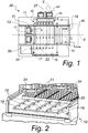
Figure 2 is a cutaway perspective view of the conditioning unit which comprises an evaporation device according to the invention; -
Figure 3 is a schematic view of the operation of the device according to the invention; -
Figure 4 is a view from above of the means for dispensing water of a device according to the invention; -
Figure 5 illustrates a first variation of the dispensing means; -
Figure 6 illustrates a second variation of the dispensing means. - With reference to the figures, a heat exchange device for air cooling for conditioning and climate control systems for server rooms and the like, according to the invention, is generally designated with the
reference numeral 10. - The
device 10 comprises: - an air/
air heat exchanger 11, designed to be passed through by aprimary air stream 12 in a main trajectory X from anintake region 13 to anoutflow region 14, and by asecondary air stream 33 along a second trajectory Y from acorresponding intake region 36 to acorresponding outflow region 37, - water dispensing means 15 adapted to wet the
heat exchanger 11 downward from above, - means 16 of collecting the water that descends from the
heat exchanger 11, - a
recirculation pump 17 for returning the air-cooling water from the collection means up to the dispensing means arranged above theheat exchanger 11. - The peculiarity of the
device 10 according to the invention consists in that the water dispensing means comprise a plurality of nozzles arranged side by side, or groups of nozzles, for example the rows ofnozzles intake region 13 toward theoutflow region 14 of theexchanger 11. - The water dispensing means, for example, comprise a plurality of rows of nozzles, each row of
nozzles intake region 13 to theoutflow region 14 of thecooling panel 11. - Each row of
nozzles - Each row of nozzles, from the
second row 19 to thelast row 23 in an order that goes from theintake region 13 to theoutflow region 14 of thecooling panel 11, dispenses overall a lower flow-rate of water than the preceding row. - The
first row 18 therefore dispenses overall a greater flow-rate of water than thesecond row 19, which in turn dispenses overall a greater flow-rate of water than thethird row 20. - In order to obtain the different flow-rates from one row of nozzles to the next, in a first variation of embodiment of the invention, which is illustrative and non-limiting thereof and is shown schematically in
Figure 5 , the rows ofnozzles first row 118 andsecond row 119 each having a greater flow-rate than a nozzle of thethird row 120 andfourth row 121. - In order to obtain the different flow-rates from one row of nozzles to the next, in a second variation of embodiment of the invention, which is illustrative and non-limiting thereof and is shown schematically in
Figure 6 , the rows ofnozzles - For example a
first row 218 has seven nozzles, asecond row 219 has six nozzles, athird row 220 has five nozzles and afourth row 221 has four nozzles. - In order to obtain the different flow-rates from one row of nozzles to the next, in a third variation of embodiment of the invention, which is illustrative and non-limiting thereof and is not shown for the sake of simplicity, the rows of nozzles comprise a different number of nozzles in one row with respect to the next, with such nozzles having a flow-rate that differs from row to row.
- In the present embodiment, the
device 10 according to the invention is shown for the purposes of example as being inserted in aconditioning unit 30, of the type with indirect free cooling, and comprises: - an air/
air heat exchanger 11, parallelepiped in shape and of known type, inside which two air streams exchange heat, aprimary air stream 12, which arrives from aserver room 40 and is directed toward this server room to be air-conditioned 40, and asecondary air stream 33, or process stream, which is drawn from outside. - The
conditioning unit 30 comprises: - the air/
air exchanger 11, - the water dispensing means 15 adapted to wet the
exchanger 11 downward from above, - the collection means 16,
- the
recirculation pump 17, -
first fans 31 for moving theprimary air stream 12, - and
second fans 34 for moving thesecondary air stream 33. - It should be understood that the invention can also be implemented in a conditioning unit of the direct free cooling type.
- With a
device 10 according to the invention, the progression of thethermal gradient 35, shown for the purposes of example inFigure 3 is exploited, such progression declining from theintake region 13 to theoutflow region 14 of theheat exchanger 11, in order to optimize the flow-rate of water to be sprayed on the exchanger. - This, as described above, can be achieved by using nozzles with different flow-rates or by using a different number of nozzles from one row to the next.
- In the area where there is a marked difference in temperature (the area where warm air returning from the data center enters the system), the device uses bigger nozzles or a greater number of nozzles with respect to the area where the difference is less marked, since it is found that in the first portion of the exchanger between 25% and 30% of the total water evaporates.
- Therefore, by distributing the flow-rate of water proportionally to the thermal gradient present along the exchanger, a greater quantity of water is sprayed where the air is capable of absorbing more, and less where it can absorb less.
- With such a device according to the invention the following advantages are obtained:
- A reduction in load losses of the exchanger, and therefore a decrease in energy consumption of the fans;
- No obstruction to the flow of air is created in the area where it absorbs less water, since less water is sprayed;
- An increase in the air flow on the process side, and therefore an increase in the performance of the conditioning unit in which the
device 10 is installed; - Since the warmest part of the exchanger is the most watered, the risk is avoided of having areas where the surface of the exchanger is no longer wetted, which can cause limescale encrustations during the most critical conditions;
- A lower flow-rate of recirculated water, with consequent reduction of the size of the pump and therefore lower energy costs;
- The range of outside conditions of operation of the unit is increased, for a given type of pump;
- Higher energy efficiency with respect to a system that has a mechanical element that moves along the exchanger in order to wet the exchange surface, since there are no moving parts, there are no dead times linked to that movement, and there is no additional electricity consumption.
- In practice it has been found that the invention fully achieves the intended aim and objects.
- In particular, with the invention an evaporation heat exchange device for air cooling for conditioning and climate control systems for server rooms and the like is provided that is capable of improving water consumption and at the same time the performance levels of the conditioning machine in which it is installed.
- With the invention an evaporation heat exchange device for air cooling for conditioning and climate control systems for server rooms and the like is provided, that simultaneously protects the integrity and the functionality of the exchanger.
- In fact, with the invention a device is provided that offers lower energy consumption and therefore less absorption of energy by the fans and pumps of the conditioning unit of which it is part.
- What is more, with the invention a device is provided that is found to be efficient in the entire wet operation range and not only in the design phase.
- Furthermore, with the invention a device is provided that makes the conditioning unit in which it is inserted more flexible in terms of possible conditions of use.
- Furthermore, with the invention a device is provided that diminishes the risk of forming encrustations on the exchanger.
- Furthermore, with the invention a device is provided that requires less recirculation of water and therefore less consumption of water owing to evaporation which does not produce any cooling effect.
- The invention thus conceived is susceptible of numerous modifications and variations, all of which are within the scope of the appended claims. Moreover, all the details may be substituted by other, technically equivalent elements.
- In practice the components and the materials employed, provided they are compatible with the specific use, and the contingent dimensions and shapes, may be any according to requirements and to the state of the art.
- The disclosures in Italian Patent Application No.
102016000033465 UA2016A002214 - Where technical features mentioned in any claim are followed by reference signs, those reference signs have been included for the sole purpose of increasing the intelligibility of the claims and accordingly, such reference signs do not have any limiting effect on the interpretation of each element identified by way of example by such reference signs.
Claims (6)
- A heat exchange device (10) for air cooling for conditioning and climate control systems for server rooms and the like, which comprises:- an air/air heat exchanger (11), designed to be passed through by a primary air stream (12) along a first trajectory (X) from an intake region (13) to an outflow region (14) and by a secondary air stream (33) along a second trajectory (Y) from a corresponding intake region (36) to a corresponding outflow region (37),- water dispensing means (15) adapted to wet said heat exchanger (11) downward from above,- means (16) of collecting the water that descends from the heat exchanger (11),- a recirculation pump (17) for returning the air-cooling water from the collection means up to the dispensing means arranged above the heat exchanger (11),being characterized in that said water dispensing means (15) comprise a plurality of nozzles arranged side by side, or rows of nozzles (18, 19, 20, 21, 22, 23), which are adapted to dispense water with a flow-rate that decreases starting from said intake region (13) for the primary air stream (12) toward said outflow region (14) of said heat exchanger (11).
- The device according to claim 1, characterized in that said water dispensing means comprise a plurality of rows of nozzles, each row of nozzles (18, 19, 20, 21, 22, 23) comprising a plurality of nozzles and being arranged side by side and in parallel in a direction going from the intake region (13) to the outflow region (14) of the heat exchanger (11).
- The device according to one or more of the preceding claims, characterized in that each row of nozzles, from a second row (19) to a last row (23) in an order that goes from the intake region (13) to the outflow region (14) of the cooling panel (11), dispenses overall a lower flow-rate of water than the preceding row.
- The device according to one or more of the preceding claims, characterized in that it comprises rows of nozzles (118, 119, 120, 121), of the dispensing means (115), which comprise an equal number of nozzles in one row with respect to the next, with said nozzles having a flow-rate that differs from row to row.
- The device according to one or more of the preceding claims, characterized in that it comprises rows of nozzles (218, 219, 220, 221), of the dispensing means (215), which comprise a different number of nozzles in one row with respect to the next, said nozzles having the same flow-rate from row to row and within the same row.
- The device according to one or more of the preceding claims, characterized in that it comprises rows of nozzles that comprise a different number of nozzles in one row with respect to the next, said nozzles having a flow-rate that differs from row to row.
Applications Claiming Priority (1)
| Application Number | Priority Date | Filing Date | Title |
|---|---|---|---|
| ITUA2016A002214A ITUA20162214A1 (en) | 2016-04-01 | 2016-04-01 | EVAPORATIVE HEAT EXCHANGE DEVICE FOR AIR COOLING FOR AIR-CONDITIONING AND AIR-CONDITIONING SYSTEMS FOR SALT SERVER AND SIMILAR |
Publications (2)
| Publication Number | Publication Date |
|---|---|
| EP3225926A1 EP3225926A1 (en) | 2017-10-04 |
| EP3225926B1 true EP3225926B1 (en) | 2018-12-12 |
Family
ID=56296979
Family Applications (1)
| Application Number | Title | Priority Date | Filing Date |
|---|---|---|---|
| EP17163764.8A Active EP3225926B1 (en) | 2016-04-01 | 2017-03-30 | Evaporation heat exchange device for air cooling for conditioning and climate control systems for server rooms and the like |
Country Status (6)
| Country | Link |
|---|---|
| US (1) | US20170290203A1 (en) |
| EP (1) | EP3225926B1 (en) |
| DK (1) | DK3225926T3 (en) |
| ES (1) | ES2714600T3 (en) |
| IT (1) | ITUA20162214A1 (en) |
| TR (1) | TR201902929T4 (en) |
Families Citing this family (4)
| Publication number | Priority date | Publication date | Assignee | Title |
|---|---|---|---|---|
| US10677544B2 (en) * | 2017-10-11 | 2020-06-09 | Schneider Electric It Corporation | System and method of water management for an indirect evaporative cooler |
| CN107979957A (en) * | 2017-12-06 | 2018-05-01 | 云南靖创液态金属热控技术研发有限公司 | A kind of jet stream heat dissipation equipment |
| CN108282972A (en) * | 2018-01-02 | 2018-07-13 | 陈炳华 | A kind of antidetonation electric control cabinet of high efficiency and heat radiation |
| CN109589521B (en) * | 2018-05-12 | 2020-09-15 | 福建旭辰信息科技有限公司 | Fire-proof emergency server protection device |
Family Cites Families (7)
| Publication number | Priority date | Publication date | Assignee | Title |
|---|---|---|---|---|
| DE4135431A1 (en) * | 1991-10-24 | 1993-05-19 | Menerga Apparatebau Gmbh | Multimode, high output room air conditioning unit - includes sections for adiabatic cooling supported by recuperative heat exchangers and refrigerator |
| EP0773412B1 (en) * | 1995-11-07 | 2003-12-17 | Kabushiki Kaisha Seibu Giken | A method and a device for refrigeration of fluid and desiccative refrigeration of gas |
| CN101303203A (en) * | 2003-03-26 | 2008-11-12 | 门图斯控股集团公司 | Plate heat exchanger |
| US7322205B2 (en) * | 2003-09-12 | 2008-01-29 | Davis Energy Group, Inc. | Hydronic rooftop cooling systems |
| GB0622355D0 (en) * | 2006-11-09 | 2006-12-20 | Oxycell Holding Bv | High efficiency heat exchanger and dehumidifier |
| US20110023506A1 (en) * | 2009-07-29 | 2011-02-03 | Day Michael S | Evaporative pre-cooler for air cooled heat exchangers |
| US9055696B2 (en) * | 2010-12-30 | 2015-06-09 | Munters Corporation | Systems for removing heat from enclosed spaces with high internal heat generation |
-
2016
- 2016-04-01 IT ITUA2016A002214A patent/ITUA20162214A1/en unknown
-
2017
- 2017-03-30 DK DK17163764.8T patent/DK3225926T3/en active
- 2017-03-30 EP EP17163764.8A patent/EP3225926B1/en active Active
- 2017-03-30 US US15/474,008 patent/US20170290203A1/en not_active Abandoned
- 2017-03-30 TR TR2019/02929T patent/TR201902929T4/en unknown
- 2017-03-30 ES ES17163764T patent/ES2714600T3/en active Active
Non-Patent Citations (1)
| Title |
|---|
| None * |
Also Published As
| Publication number | Publication date |
|---|---|
| DK3225926T3 (en) | 2019-03-11 |
| TR201902929T4 (en) | 2019-03-21 |
| EP3225926A1 (en) | 2017-10-04 |
| ES2714600T3 (en) | 2019-05-29 |
| ITUA20162214A1 (en) | 2017-10-01 |
| US20170290203A1 (en) | 2017-10-05 |
Similar Documents
| Publication | Publication Date | Title |
|---|---|---|
| EP3225926B1 (en) | Evaporation heat exchange device for air cooling for conditioning and climate control systems for server rooms and the like | |
| JP6270983B2 (en) | Cooling tower with indirect heat exchanger | |
| EP3158271B1 (en) | Systems and methods for managing conditions in enclosed space | |
| US9140471B2 (en) | Indirect evaporative coolers with enhanced heat transfer | |
| CN106662405B (en) | Combined convector | |
| US9822990B2 (en) | Methods, systems, and devices for humidifying | |
| JP6147537B2 (en) | Air conditioner | |
| JP2015064195A (en) | Air for wet type cooling tower device-air heat exchanger bypass and method | |
| US20130333407A1 (en) | Sub-wet bulb evaporative chiller system with multiple integrated subunits or chillers | |
| CN102809314A (en) | Three-dimensional heat-pipe heat exchanger and production method thereof | |
| JP6553981B2 (en) | Heat exchange equipment for heat pump equipment | |
| CN202329317U (en) | Split type heat pipe heat exchanger | |
| JP2008292106A (en) | Cooling tower system | |
| US10718534B2 (en) | Air conditioner having an improved outdoor unit | |
| KR20060100419A (en) | Heat exchange laminate | |
| US20070138662A1 (en) | Closed evaporative cooling tower | |
| EP3213000B1 (en) | System and method of cooling by latent energy transfer | |
| CN104832997A (en) | Air conditioning unit and indoor unit thereof | |
| RU2614623C2 (en) | Air precooler in the air cooling devices | |
| EP2910864B1 (en) | Water cooling unit for conditioning systems | |
| KR101506214B1 (en) | Evaporative Cooling-type Exhaust Air Heat Recovery System | |
| CN201285231Y (en) | Plate-type evaporative cooler | |
| SHARIATI et al. | An investigation of indirect evaporative coolers, IEC with respect to thermal comfort criteria | |
| JP2011174629A (en) | Air conditioner | |
| KR101589541B1 (en) | Evaporative Cooling Heat Exchange |
Legal Events
| Date | Code | Title | Description |
|---|---|---|---|
| PUAI | Public reference made under article 153(3) epc to a published international application that has entered the european phase |
Free format text: ORIGINAL CODE: 0009012 |
|
| STAA | Information on the status of an ep patent application or granted ep patent |
Free format text: STATUS: THE APPLICATION HAS BEEN PUBLISHED |
|
| AK | Designated contracting states |
Kind code of ref document: A1 Designated state(s): AL AT BE BG CH CY CZ DE DK EE ES FI FR GB GR HR HU IE IS IT LI LT LU LV MC MK MT NL NO PL PT RO RS SE SI SK SM TR |
|
| AX | Request for extension of the european patent |
Extension state: BA ME |
|
| STAA | Information on the status of an ep patent application or granted ep patent |
Free format text: STATUS: REQUEST FOR EXAMINATION WAS MADE |
|
| RAP1 | Party data changed (applicant data changed or rights of an application transferred) |
Owner name: VERTIV S.R.L. |
|
| 17P | Request for examination filed |
Effective date: 20171222 |
|
| RBV | Designated contracting states (corrected) |
Designated state(s): AL AT BE BG CH CY CZ DE DK EE ES FI FR GB GR HR HU IE IS IT LI LT LU LV MC MK MT NL NO PL PT RO RS SE SI SK SM TR |
|
| RIC1 | Information provided on ipc code assigned before grant |
Ipc: H05K 7/20 20060101ALI20180509BHEP Ipc: F24F 12/00 20060101ALI20180509BHEP Ipc: F24F 3/14 20060101ALI20180509BHEP Ipc: F24F 5/00 20060101AFI20180509BHEP |
|
| GRAP | Despatch of communication of intention to grant a patent |
Free format text: ORIGINAL CODE: EPIDOSNIGR1 |
|
| STAA | Information on the status of an ep patent application or granted ep patent |
Free format text: STATUS: GRANT OF PATENT IS INTENDED |
|
| INTG | Intention to grant announced |
Effective date: 20180618 |
|
| GRAS | Grant fee paid |
Free format text: ORIGINAL CODE: EPIDOSNIGR3 |
|
| GRAA | (expected) grant |
Free format text: ORIGINAL CODE: 0009210 |
|
| STAA | Information on the status of an ep patent application or granted ep patent |
Free format text: STATUS: THE PATENT HAS BEEN GRANTED |
|
| AK | Designated contracting states |
Kind code of ref document: B1 Designated state(s): AL AT BE BG CH CY CZ DE DK EE ES FI FR GB GR HR HU IE IS IT LI LT LU LV MC MK MT NL NO PL PT RO RS SE SI SK SM TR |
|
| REG | Reference to a national code |
Ref country code: GB Ref legal event code: FG4D |
|
| REG | Reference to a national code |
Ref country code: CH Ref legal event code: EP |
|
| REG | Reference to a national code |
Ref country code: AT Ref legal event code: REF Ref document number: 1076542 Country of ref document: AT Kind code of ref document: T Effective date: 20181215 |
|
| REG | Reference to a national code |
Ref country code: DE Ref legal event code: R096 Ref document number: 602017001286 Country of ref document: DE |
|
| REG | Reference to a national code |
Ref country code: IE Ref legal event code: FG4D |
|
| REG | Reference to a national code |
Ref country code: NL Ref legal event code: FP |
|
| REG | Reference to a national code |
Ref country code: DK Ref legal event code: T3 Effective date: 20190304 |
|
| REG | Reference to a national code |
Ref country code: SE Ref legal event code: TRGR |
|
| REG | Reference to a national code |
Ref country code: LT Ref legal event code: MG4D |
|
| PG25 | Lapsed in a contracting state [announced via postgrant information from national office to epo] |
Ref country code: FI Free format text: LAPSE BECAUSE OF FAILURE TO SUBMIT A TRANSLATION OF THE DESCRIPTION OR TO PAY THE FEE WITHIN THE PRESCRIBED TIME-LIMIT Effective date: 20181212 Ref country code: LT Free format text: LAPSE BECAUSE OF FAILURE TO SUBMIT A TRANSLATION OF THE DESCRIPTION OR TO PAY THE FEE WITHIN THE PRESCRIBED TIME-LIMIT Effective date: 20181212 Ref country code: NO Free format text: LAPSE BECAUSE OF FAILURE TO SUBMIT A TRANSLATION OF THE DESCRIPTION OR TO PAY THE FEE WITHIN THE PRESCRIBED TIME-LIMIT Effective date: 20190312 Ref country code: HR Free format text: LAPSE BECAUSE OF FAILURE TO SUBMIT A TRANSLATION OF THE DESCRIPTION OR TO PAY THE FEE WITHIN THE PRESCRIBED TIME-LIMIT Effective date: 20181212 Ref country code: LV Free format text: LAPSE BECAUSE OF FAILURE TO SUBMIT A TRANSLATION OF THE DESCRIPTION OR TO PAY THE FEE WITHIN THE PRESCRIBED TIME-LIMIT Effective date: 20181212 Ref country code: BG Free format text: LAPSE BECAUSE OF FAILURE TO SUBMIT A TRANSLATION OF THE DESCRIPTION OR TO PAY THE FEE WITHIN THE PRESCRIBED TIME-LIMIT Effective date: 20190312 |
|
| REG | Reference to a national code |
Ref country code: AT Ref legal event code: MK05 Ref document number: 1076542 Country of ref document: AT Kind code of ref document: T Effective date: 20181212 |
|
| REG | Reference to a national code |
Ref country code: ES Ref legal event code: FG2A Ref document number: 2714600 Country of ref document: ES Kind code of ref document: T3 Effective date: 20190529 |
|
| PG25 | Lapsed in a contracting state [announced via postgrant information from national office to epo] |
Ref country code: AL Free format text: LAPSE BECAUSE OF FAILURE TO SUBMIT A TRANSLATION OF THE DESCRIPTION OR TO PAY THE FEE WITHIN THE PRESCRIBED TIME-LIMIT Effective date: 20181212 Ref country code: GR Free format text: LAPSE BECAUSE OF FAILURE TO SUBMIT A TRANSLATION OF THE DESCRIPTION OR TO PAY THE FEE WITHIN THE PRESCRIBED TIME-LIMIT Effective date: 20190313 Ref country code: RS Free format text: LAPSE BECAUSE OF FAILURE TO SUBMIT A TRANSLATION OF THE DESCRIPTION OR TO PAY THE FEE WITHIN THE PRESCRIBED TIME-LIMIT Effective date: 20181212 |
|
| PG25 | Lapsed in a contracting state [announced via postgrant information from national office to epo] |
Ref country code: CZ Free format text: LAPSE BECAUSE OF FAILURE TO SUBMIT A TRANSLATION OF THE DESCRIPTION OR TO PAY THE FEE WITHIN THE PRESCRIBED TIME-LIMIT Effective date: 20181212 Ref country code: PT Free format text: LAPSE BECAUSE OF FAILURE TO SUBMIT A TRANSLATION OF THE DESCRIPTION OR TO PAY THE FEE WITHIN THE PRESCRIBED TIME-LIMIT Effective date: 20190412 Ref country code: PL Free format text: LAPSE BECAUSE OF FAILURE TO SUBMIT A TRANSLATION OF THE DESCRIPTION OR TO PAY THE FEE WITHIN THE PRESCRIBED TIME-LIMIT Effective date: 20181212 |
|
| PG25 | Lapsed in a contracting state [announced via postgrant information from national office to epo] |
Ref country code: IS Free format text: LAPSE BECAUSE OF FAILURE TO SUBMIT A TRANSLATION OF THE DESCRIPTION OR TO PAY THE FEE WITHIN THE PRESCRIBED TIME-LIMIT Effective date: 20190412 Ref country code: SK Free format text: LAPSE BECAUSE OF FAILURE TO SUBMIT A TRANSLATION OF THE DESCRIPTION OR TO PAY THE FEE WITHIN THE PRESCRIBED TIME-LIMIT Effective date: 20181212 Ref country code: RO Free format text: LAPSE BECAUSE OF FAILURE TO SUBMIT A TRANSLATION OF THE DESCRIPTION OR TO PAY THE FEE WITHIN THE PRESCRIBED TIME-LIMIT Effective date: 20181212 Ref country code: EE Free format text: LAPSE BECAUSE OF FAILURE TO SUBMIT A TRANSLATION OF THE DESCRIPTION OR TO PAY THE FEE WITHIN THE PRESCRIBED TIME-LIMIT Effective date: 20181212 Ref country code: SM Free format text: LAPSE BECAUSE OF FAILURE TO SUBMIT A TRANSLATION OF THE DESCRIPTION OR TO PAY THE FEE WITHIN THE PRESCRIBED TIME-LIMIT Effective date: 20181212 |
|
| REG | Reference to a national code |
Ref country code: DE Ref legal event code: R097 Ref document number: 602017001286 Country of ref document: DE |
|
| PLBE | No opposition filed within time limit |
Free format text: ORIGINAL CODE: 0009261 |
|
| STAA | Information on the status of an ep patent application or granted ep patent |
Free format text: STATUS: NO OPPOSITION FILED WITHIN TIME LIMIT |
|
| PG25 | Lapsed in a contracting state [announced via postgrant information from national office to epo] |
Ref country code: MC Free format text: LAPSE BECAUSE OF FAILURE TO SUBMIT A TRANSLATION OF THE DESCRIPTION OR TO PAY THE FEE WITHIN THE PRESCRIBED TIME-LIMIT Effective date: 20181212 Ref country code: AT Free format text: LAPSE BECAUSE OF FAILURE TO SUBMIT A TRANSLATION OF THE DESCRIPTION OR TO PAY THE FEE WITHIN THE PRESCRIBED TIME-LIMIT Effective date: 20181212 Ref country code: SI Free format text: LAPSE BECAUSE OF FAILURE TO SUBMIT A TRANSLATION OF THE DESCRIPTION OR TO PAY THE FEE WITHIN THE PRESCRIBED TIME-LIMIT Effective date: 20181212 |
|
| 26N | No opposition filed |
Effective date: 20190913 |
|
| PG25 | Lapsed in a contracting state [announced via postgrant information from national office to epo] |
Ref country code: LU Free format text: LAPSE BECAUSE OF NON-PAYMENT OF DUE FEES Effective date: 20190330 |
|
| PG25 | Lapsed in a contracting state [announced via postgrant information from national office to epo] |
Ref country code: MT Free format text: LAPSE BECAUSE OF NON-PAYMENT OF DUE FEES Effective date: 20190330 |
|
| REG | Reference to a national code |
Ref country code: CH Ref legal event code: PL |
|
| PG25 | Lapsed in a contracting state [announced via postgrant information from national office to epo] |
Ref country code: CH Free format text: LAPSE BECAUSE OF NON-PAYMENT OF DUE FEES Effective date: 20200331 Ref country code: LI Free format text: LAPSE BECAUSE OF NON-PAYMENT OF DUE FEES Effective date: 20200331 |
|
| PG25 | Lapsed in a contracting state [announced via postgrant information from national office to epo] |
Ref country code: CY Free format text: LAPSE BECAUSE OF FAILURE TO SUBMIT A TRANSLATION OF THE DESCRIPTION OR TO PAY THE FEE WITHIN THE PRESCRIBED TIME-LIMIT Effective date: 20181212 |
|
| PG25 | Lapsed in a contracting state [announced via postgrant information from national office to epo] |
Ref country code: HU Free format text: LAPSE BECAUSE OF FAILURE TO SUBMIT A TRANSLATION OF THE DESCRIPTION OR TO PAY THE FEE WITHIN THE PRESCRIBED TIME-LIMIT; INVALID AB INITIO Effective date: 20170330 |
|
| PG25 | Lapsed in a contracting state [announced via postgrant information from national office to epo] |
Ref country code: MK Free format text: LAPSE BECAUSE OF FAILURE TO SUBMIT A TRANSLATION OF THE DESCRIPTION OR TO PAY THE FEE WITHIN THE PRESCRIBED TIME-LIMIT Effective date: 20181212 |
|
| PGFP | Annual fee paid to national office [announced via postgrant information from national office to epo] |
Ref country code: IE Payment date: 20230327 Year of fee payment: 7 Ref country code: FR Payment date: 20230327 Year of fee payment: 7 Ref country code: DK Payment date: 20230329 Year of fee payment: 7 |
|
| PGFP | Annual fee paid to national office [announced via postgrant information from national office to epo] |
Ref country code: TR Payment date: 20230316 Year of fee payment: 7 Ref country code: SE Payment date: 20230315 Year of fee payment: 7 Ref country code: IT Payment date: 20230321 Year of fee payment: 7 Ref country code: BE Payment date: 20230327 Year of fee payment: 7 |
|
| P01 | Opt-out of the competence of the unified patent court (upc) registered |
Effective date: 20230621 |
|
| PGFP | Annual fee paid to national office [announced via postgrant information from national office to epo] |
Ref country code: ES Payment date: 20230403 Year of fee payment: 7 |
|
| PGFP | Annual fee paid to national office [announced via postgrant information from national office to epo] |
Ref country code: IE Payment date: 20240327 Year of fee payment: 8 Ref country code: NL Payment date: 20240326 Year of fee payment: 8 |
|
| PGFP | Annual fee paid to national office [announced via postgrant information from national office to epo] |
Ref country code: DE Payment date: 20240327 Year of fee payment: 8 Ref country code: GB Payment date: 20240327 Year of fee payment: 8 |