EP3225815A1 - Translating inlet for adjusting airflow distortion in gas turbine engine - Google Patents
Translating inlet for adjusting airflow distortion in gas turbine engine Download PDFInfo
- Publication number
- EP3225815A1 EP3225815A1 EP17163223.5A EP17163223A EP3225815A1 EP 3225815 A1 EP3225815 A1 EP 3225815A1 EP 17163223 A EP17163223 A EP 17163223A EP 3225815 A1 EP3225815 A1 EP 3225815A1
- Authority
- EP
- European Patent Office
- Prior art keywords
- engine
- airflow
- translating
- inlet
- inlet assembly
- Prior art date
- Legal status (The legal status is an assumption and is not a legal conclusion. Google has not performed a legal analysis and makes no representation as to the accuracy of the status listed.)
- Granted
Links
- 238000000034 method Methods 0.000 claims abstract description 31
- 238000002485 combustion reaction Methods 0.000 claims abstract description 20
- 238000005259 measurement Methods 0.000 claims description 18
- 239000007789 gas Substances 0.000 description 103
- 238000004891 communication Methods 0.000 description 10
- 239000000567 combustion gas Substances 0.000 description 8
- 230000004044 response Effects 0.000 description 6
- 238000009530 blood pressure measurement Methods 0.000 description 4
- 239000012530 fluid Substances 0.000 description 4
- 238000011144 upstream manufacturing Methods 0.000 description 4
- 230000008901 benefit Effects 0.000 description 3
- 230000003247 decreasing effect Effects 0.000 description 3
- 230000007246 mechanism Effects 0.000 description 3
- 238000012986 modification Methods 0.000 description 3
- 230000004048 modification Effects 0.000 description 3
- 230000001141 propulsive effect Effects 0.000 description 3
- 238000010586 diagram Methods 0.000 description 2
- 239000000446 fuel Substances 0.000 description 2
- 238000012545 processing Methods 0.000 description 2
- 230000004913 activation Effects 0.000 description 1
- 238000013459 approach Methods 0.000 description 1
- 230000009286 beneficial effect Effects 0.000 description 1
- 238000005516 engineering process Methods 0.000 description 1
- 230000037361 pathway Effects 0.000 description 1
- 230000008569 process Effects 0.000 description 1
- 238000000926 separation method Methods 0.000 description 1
- 239000007787 solid Substances 0.000 description 1
- 239000013589 supplement Substances 0.000 description 1
Images


Classifications
-
- F—MECHANICAL ENGINEERING; LIGHTING; HEATING; WEAPONS; BLASTING
- F02—COMBUSTION ENGINES; HOT-GAS OR COMBUSTION-PRODUCT ENGINE PLANTS
- F02K—JET-PROPULSION PLANTS
- F02K3/00—Plants including a gas turbine driving a compressor or a ducted fan
- F02K3/02—Plants including a gas turbine driving a compressor or a ducted fan in which part of the working fluid by-passes the turbine and combustion chamber
- F02K3/04—Plants including a gas turbine driving a compressor or a ducted fan in which part of the working fluid by-passes the turbine and combustion chamber the plant including ducted fans, i.e. fans with high volume, low pressure outputs, for augmenting the jet thrust, e.g. of double-flow type
- F02K3/075—Plants including a gas turbine driving a compressor or a ducted fan in which part of the working fluid by-passes the turbine and combustion chamber the plant including ducted fans, i.e. fans with high volume, low pressure outputs, for augmenting the jet thrust, e.g. of double-flow type controlling flow ratio between flows
-
- F—MECHANICAL ENGINEERING; LIGHTING; HEATING; WEAPONS; BLASTING
- F02—COMBUSTION ENGINES; HOT-GAS OR COMBUSTION-PRODUCT ENGINE PLANTS
- F02C—GAS-TURBINE PLANTS; AIR INTAKES FOR JET-PROPULSION PLANTS; CONTROLLING FUEL SUPPLY IN AIR-BREATHING JET-PROPULSION PLANTS
- F02C7/00—Features, components parts, details or accessories, not provided for in, or of interest apart form groups F02C1/00 - F02C6/00; Air intakes for jet-propulsion plants
- F02C7/04—Air intakes for gas-turbine plants or jet-propulsion plants
- F02C7/057—Control or regulation
-
- F—MECHANICAL ENGINEERING; LIGHTING; HEATING; WEAPONS; BLASTING
- F02—COMBUSTION ENGINES; HOT-GAS OR COMBUSTION-PRODUCT ENGINE PLANTS
- F02C—GAS-TURBINE PLANTS; AIR INTAKES FOR JET-PROPULSION PLANTS; CONTROLLING FUEL SUPPLY IN AIR-BREATHING JET-PROPULSION PLANTS
- F02C3/00—Gas-turbine plants characterised by the use of combustion products as the working fluid
- F02C3/04—Gas-turbine plants characterised by the use of combustion products as the working fluid having a turbine driving a compressor
-
- F—MECHANICAL ENGINEERING; LIGHTING; HEATING; WEAPONS; BLASTING
- F02—COMBUSTION ENGINES; HOT-GAS OR COMBUSTION-PRODUCT ENGINE PLANTS
- F02C—GAS-TURBINE PLANTS; AIR INTAKES FOR JET-PROPULSION PLANTS; CONTROLLING FUEL SUPPLY IN AIR-BREATHING JET-PROPULSION PLANTS
- F02C7/00—Features, components parts, details or accessories, not provided for in, or of interest apart form groups F02C1/00 - F02C6/00; Air intakes for jet-propulsion plants
- F02C7/04—Air intakes for gas-turbine plants or jet-propulsion plants
- F02C7/042—Air intakes for gas-turbine plants or jet-propulsion plants having variable geometry
-
- F—MECHANICAL ENGINEERING; LIGHTING; HEATING; WEAPONS; BLASTING
- F02—COMBUSTION ENGINES; HOT-GAS OR COMBUSTION-PRODUCT ENGINE PLANTS
- F02C—GAS-TURBINE PLANTS; AIR INTAKES FOR JET-PROPULSION PLANTS; CONTROLLING FUEL SUPPLY IN AIR-BREATHING JET-PROPULSION PLANTS
- F02C9/00—Controlling gas-turbine plants; Controlling fuel supply in air- breathing jet-propulsion plants
- F02C9/16—Control of working fluid flow
- F02C9/20—Control of working fluid flow by throttling; by adjusting vanes
-
- F—MECHANICAL ENGINEERING; LIGHTING; HEATING; WEAPONS; BLASTING
- F04—POSITIVE - DISPLACEMENT MACHINES FOR LIQUIDS; PUMPS FOR LIQUIDS OR ELASTIC FLUIDS
- F04D—NON-POSITIVE-DISPLACEMENT PUMPS
- F04D27/00—Control, e.g. regulation, of pumps, pumping installations or pumping systems specially adapted for elastic fluids
- F04D27/02—Surge control
- F04D27/0253—Surge control by throttling
-
- F—MECHANICAL ENGINEERING; LIGHTING; HEATING; WEAPONS; BLASTING
- F05—INDEXING SCHEMES RELATING TO ENGINES OR PUMPS IN VARIOUS SUBCLASSES OF CLASSES F01-F04
- F05D—INDEXING SCHEME FOR ASPECTS RELATING TO NON-POSITIVE-DISPLACEMENT MACHINES OR ENGINES, GAS-TURBINES OR JET-PROPULSION PLANTS
- F05D2270/00—Control
- F05D2270/01—Purpose of the control system
- F05D2270/10—Purpose of the control system to cope with, or avoid, compressor flow instabilities
- F05D2270/101—Compressor surge or stall
Definitions
- the present subject matter relates generally to gas turbine engines and more particularly to a translating inlet for adjusting airflow distortion in a gas turbine engine.
- a gas turbine engine generally includes a core having, in serial flow order, a compressor section, a combustion section, a turbine section, and an exhaust section.
- an engine airflow is provided to an inlet of the compressor section where one or more axial compressors progressively compress the air until it reaches the combustion section.
- Fuel is mixed with the compressed air and burned within the combustion section to provide combustion gases.
- the combustion gases are routed from the combustion section to the turbine section.
- the flow of combustion gasses through the turbine section drives the compressor section and is then routed through the exhaust section, e.g., to atmosphere.
- the gas turbine engine may encounter airflow distortion in the engine airflow path upstream of the compressor section, such as a circumferential or local flow disruption due to the angle of attack of the gas turbine engine, a cross wind, or any other inlet anomaly.
- Airflow distortion can be so uneven during operation as to put portions of the compressor section at or below proper stall pressure ratios. In many cases, sufficient stall margin should be maintained in the compressor section in order to prevent stall conditions from occurring during operation of the gas turbine engine.
- variable guide vanes At the inlet to the compressor section, thereby reducing air flow and pressure in the compressor section below a pressure sufficient to cause stall conditions.
- closing the variable guide vanes can decrease the overall efficiency of the gas turbine engine.
- the core engine can include a compressor section, a combustion section, and a turbine section in series flow and defining at least in part an engine airflow path for the gas turbine engine.
- the core engine can also include an inner flowpath surface positioned at least partially within the compressor section and defining at least in part the engine airflow path.
- the core engine can also include a core casing at least partially enclosing the compressor section and defining a forward end.
- the core casing can include a translating inlet assembly at the forward end.
- the translating inlet assembly and inner flowpath surface can together define an inlet to the compressor section.
- the translating inlet assembly can be moveable between a first position defining a first inlet area at the inlet and a second position defining a second inlet area at the inlet, with the first inlet area being greater than the second inlet area.
- the gas turbine engine can include a compressor section, a combustion section, and a turbine section in series flow.
- the compressor section, combustion section, and turbine section can define at least in part an engine airflow path.
- the gas turbine engine can include an inner flow path surface positioned at least partially within the compressor section and defining at least in part the engine airflow path.
- the gas turbine engine can include a core casing at least partially enclosing the compressor section and defining a forward end.
- the method includes determining, by one or more control devices, an airflow distortion condition associated with the engine airflow path.
- the method can also include controlling, by the one or more control devices, a translating inlet assembly to adjust the airflow distortion condition of the gas turbine engine.
- the core casing can include the translating inlet assembly at the forward end.
- the translating inlet assembly and inner flow path surface can together define an inlet to the compressor section.
- the translating inlet assembly can be moveable between a first position defining a first inlet area and a second position defining a second inlet area, with the first inlet area being greater than the second inlet area.
- example aspects of the present disclosure are directed to gas turbine engines, devices, apparatus, and other systems configured to adjust airflow distortion in the airflow path of a gas turbine engine. Variations and modifications can be made to these example aspects of the present disclosure.
- Example aspects of the present disclosure are directed to adjusting airflow distortion in a gas turbine engine in real-time.
- Airflow distortion can be so uneven during operation of the gas turbine engine as to put portions of the compressor section at or below proper stall pressure ratios, thereby reducing the operability of the gas turbine engine.
- Increased stall margin headroom can therefore be necessary to account for airflow distortion.
- the gas turbine engine and method according to example aspects of the present disclosure can increase the operability of the aircraft's gas turbine engine by making a real-time assessment of airflow distortion in the engine airflow path of the gas turbine engine and adjusting the airflow distortion in the engine airflow path by operating a translating inlet assembly to vary the amount and/or speed of airflow into the engine airflow path of the gas turbine engine based on the airflow distortion assessment.
- Real-time pressure measurements obtained from the engine airflow path can be used to make an assessment of airflow distortion conditions in the gas turbine engine.
- Airflow distortion in the engine airflow path can then be adjusted by opening or closing the translating inlet assembly to increase or decrease the amount of airflow and/or airflow speed into the engine airflow path.
- a translating inlet assembly can be used to vary the amount and/or speed of airflow entering the engine airflow path in a gas turbine engine in response to airflow distortion in the engine airflow path.
- the gas turbine engine can include a compressor section, a combustion section, and a turbine section series flow and enclosed by a casing.
- the gas turbine engine can include a translating inlet assembly at a forward end of the casing.
- An engine airflow can enter the gas turbine engine through an inlet to the compressor section between a front edge of the translating inlet assembly and an inner flowpath surface. The engine airflow can then flow through the engine airflow path of the gas turbine engine.
- the front edge of the translating inlet assembly can be configured to move between a first position and a second position in order to vary the area of the inlet to the compressor section.
- the front edge of the translating inlet assembly can move generally along an axial direction in order to increase or decrease the inlet area about the circumference of the inlet of the compressor section of the gas turbine engine.
- the front edge of the translating inlet assembly can move between a first position and a second position such that the front edge of the translating inlet assembly translates at least partially along a radial direction to increase or decrease the inlet area.
- the translating inlet assembly can move between the first position and the second position in a generally uniform manner about the circumference of the gas turbine engine such that the inlet area of the compressor section is generally uniform about the entire circumference of the inlet.
- the translating inlet assembly can move to one or more intermediate positions such that the inlet area in the one or more intermediate positions is less than the inlet area in the first position and more than the inlet area in the second position.
- the translating inlet assembly can be configured to be controlled to move between positions in response to airflow distortion.
- one or more pressure sensing devices can be integrated into various components that extend into the engine airflow path of the gas turbine engine.
- a distortion condition assessment can be made based on the real-time pressure measurements obtained from the pressure sensing devices. For example, a non-uniform pressure profile across the engine airflow path can indicate that airflow distortion is present in the engine airflow path.
- the translating inlet assembly can then be controlled to adjust the airflow distortion associated with the engine airflow path.
- the translating inlet assembly can be controlled to increase or reduce the inlet area of the compressor section to allow or restrict airflow into the engine airflow path, thereby reducing the airflow distortion.
- the gas turbine engine and method according to example aspects of the present disclosure can have a beneficial effect of adjusting the airflow distortion of the gas turbine engine based on real-time airflow distortion conditions. Further, this can allow an increase in the operability of the gas turbine engine by increasing the stall margin headroom available for operational safety.
- FIG. 1 is a schematic cross-sectional view of a gas turbine engine in accordance with an example embodiment of the present disclosure. More particularly, for the embodiment of FIG. 1 , the gas turbine engine is a high-bypass turbofan jet engine 10, referred to herein as "gas turbine engine 10." Example aspects of the present disclosure can be used with other suitable gas turbine engines without deviating from the scope of the present disclosure.
- the gas turbine engine 10 defines an axial direction A (extending parallel to a longitudinal centerline 12 provided for reference) and a radial direction R.
- the gas turbine engine 10 also defines a circumferential direction (not depicted).
- the gas turbine engine 10 includes a fan section 14 and a core engine 16, the fan section 14 configured in mechanical communication and positioned in flow communication with the core engine 16.
- the example core engine 16 depicted generally includes a substantially tubular outer casing 18 which defines a forward end that includes a translating inlet assembly 112. Translating inlet assembly 112 and an inner flowpath surface 114 together define an annular inlet 20.
- the outer casing 18 encases, in serial flow relationship, a compressor section including a booster or low pressure (LP) compressor 22 and a high pressure (HP) compressor 24; a combustion section 26; a turbine section including a high pressure (HP) turbine 28 and a low pressure (LP) turbine 30; and a jet exhaust nozzle section 32.
- a high pressure (HP) shaft or spool 34 drivingly connects the HP turbine 28 to the HP compressor 24.
- a low pressure (LP) shaft or spool 36 drivingly connects the LP turbine 30 to the LP compressor 22.
- the fan section 14 includes a variable pitch fan 38 having a plurality of fan blades 40 coupled to a disk 42 in a spaced apart manner.
- the fan blades 40 extend outwardly from the disk 42 generally along the radial direction R.
- the fan blades 40 and disk 42 are together rotatable about the longitudinal centerline 12 by LP shaft 36 across a power gear box 44.
- the power gear box 44 includes a plurality of gears for adjusting the rotational speed of the LP shaft 36.
- the disk 42 of the variable pitch fan 38 is covered by a rotatable front hub 46 aerodynamically contoured to promote an airflow through the plurality of fan blades 40.
- the example gas turbine engine 10 additionally includes a plurality of circumferentially-spaced outlet guide vanes 50.
- the plurality of outlet guide vanes 50 are positioned downstream from the fan 38 along the axial direction A and extend outwardly from the outer casing 18 of the core engine 16 generally along the radial direction R.
- Each outlet guide vane 50 defines a center of pressure 52 (shown in FIG. 2 ) and a pitch axis P extending substantially parallel to the radial direction R.
- the gas turbine engine 10 does not include any outer casing enclosing the fan section 14 and/or outlet guide vanes 50. Accordingly, for the embodiment depicted, the gas turbine engine 10 may be referred to as an un-ducted single fan gas turbine engine 10.
- the fan section 14, or more particularly, the rotation of the fan blades 40 of the fan section 14, provides a majority of the propulsive thrust of the gas turbine engine 10.
- the plurality of outlet guide vanes 50 are provided to increase an efficiency of the fan section 14 as well as to provide other benefits, such as, for example, decreasing an amount of noise generated by the gas turbine engine 10.
- a volume of air 56 passes over the plurality of blades 40 of the fan section 14.
- a first portion of the volume of air 56 i.e., the first portion of air 60
- the first portion of air 60 may also be referred to as an engine airflow.
- a second portion of the volume of air 56 e.g., a second portion of air 62
- the second portion of air 62 may also be referred to as a bypass airflow.
- the ratio between the second portion of air 62 and the first portion of air 60 is commonly known as a bypass ratio.
- the pressure of the first portion of air 60 is increased as it is routed through the LP compressor 22 and subsequently through the HP compressor 24.
- the compressed first portion of air 60 is then provided to the combustion section 26, where it is mixed with fuel and burned to provide combustion gases 74.
- the combustion gases 74 are routed through the HP turbine 28 where a portion of thermal and/or kinetic energy from the combustion gases 74 is extracted via sequential stages of HP turbine stator vanes 76 that are coupled to the outer casing 18 and HP turbine rotor blades 78 that are coupled to the HP shaft or spool 34, thus causing the HP shaft or spool 34 to rotate, thereby supporting operation of the HP compressor 24.
- the combustion gases 74 are then routed through the LP turbine 30 where a second portion of thermal and kinetic energy is extracted from the combustion gases 74 via sequential stages of LP turbine stator vanes 80 that are coupled to the outer casing 18 and LP turbine rotor blades 82 that are coupled to the LP shaft or spool 36, thus causing the LP shaft or spool 36 to rotate, thereby supporting operation of the LP compressor 22 and/or rotation of the fan 38.
- the combustion gases 74 are subsequently routed through the jet exhaust nozzle section 32 of the core engine 16 to provide propulsive thrust to supplement propulsive thrust provided by the fan section 14.
- inlet guide vane 100 downstream of an annular inlet 20 is one or more inlet guide vanes 100.
- inlet guide vane 100 may be configured to open or close, thereby restricting the flow of the first portion of air 60 into the engine airflow path 64 extending through the compressor section.
- inlet guide vane 100 can be an instrumented guide vane 400 according to example embodiments of the present disclosure as depicted, for instance, in FIGS. 8 and 9 .
- variable guide vane 104 Downstream of inlet guide vane 100 is one or more struts 102 configured to mechanically couple outer casing 18 to the core engine 16. Strut 102 extends into the engine airflow path 64 where first portion of air 60 flows over strut 102. In certain example embodiments, strut 102 is configured to obtain pressure measurements. Downstream of strut 102 is one or more variable guide vanes 104. Variable guide vanes 104 are configured to open or close, thereby restricting the flow of the first portion of air 60 into the engine airflow path 64 extending through the compressor section. In certain example embodiments, variable guide vane 104 can be an instrumented variable guide vane 400 according to example embodiments of the present disclosure as shown, for instance, in FIGS. 8 and 9 .
- the gas turbine engine 10 includes at least one control mechanism 106 configured to adjust a variable guide vane 104.
- the gas turbine engine 10 may include a plurality of control mechanisms 106, each individual control mechanism 106 configured to adjust an individual variable guide vane 104 or other member of the airflow path.
- translating inlet assembly 112 is located on the forward end of outer casing 18.
- core engine 16 can include an inner flowpath surface 114.
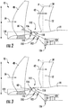
- Translating inlet assembly 112 can include a front edge 116 which can be moved by one or more actuators 118.
- a plurality of actuators 118 can be spaced about the circumferential direction of gas turbine engine 10 to move front edge 116.
- front edge 116 and inner flowpath surface 114 can define annular inlet 20, as shown in FIG. 1 .
- front edge 116 can be moved at least partially along radial direction R between a first position and a second position.
- front edge 116 is in a first position such that front edge 116 defines a first radius 120.
- front edge 116 is in a second position such that front edge 116 defines a second radius 122.
- first radius 120 is greater than second radius 122.
- first portion of air 60 enters core engine 16 by passing between front edge 116 and inner flowpath surface 114.
- front edge 116 in the first position allows an increased first portion of air 60 to enter engine flowpath 64 as compared to front edge 116 in the second position.
- front edge 116 can be moved to one or more intermediate positions such that the first portion of air 60 in the intermediate position is less than the first portion of air 60 in the first position and more than the first portion of air 60 in the second position.
- front edge 116 can be moved in response to a signal from a control device, such as, for instance, control device 1000 depicted in FIG. 10 .
- a control device such as, for instance, control device 1000 depicted in FIG. 10 .
- front edge 116 can be moved in response to a control signal sent to one or more actuators 118 that controls the one or more actuators 118 to move front edge 116 to a particular setpoint, such as the first, second, or intermediate positions.
- the amount of airflow and/or the speed of airflow that flows through engine airflow path 64 can be varied, thereby allowing the performance of annular inlet 20 to be varied to match the airflow demand of the LP compressor 22.
- translating inlet assembly 112 can be controlled to move front edge 116 to move between the first, second, and intermediate positions to allow the performance of annular inlet 20 to be varied to adjust airflow distortion to improve the operability of gas turbine engine 10, or increase the stall margin of LP compressor 22.
- adjusting the airflow distortion may include adjusting an inlet airflow distortion and/or adjusting an airflow mismatch and/or airflow speed mismatch between LP compressor 22 and HP compressor 24. Airflow and/or airflow speed mismatch can occur because fans, such as variable pitch fan 38 in gas turbine engine 10, may operate within a narrow speed range, which may be elevated.
- low pressure compressors such as LP compressor 22 may operate at a similarly elevated speed because they are mechanically coupled to the variable pitch fan through a gearbox.
- a low pressure compressor such as LP compressor 22 may pump too much airflow for a high pressure compressor, such as HP compressor 24, to accept.
- gas turbine engine 10 includes outer casing 18.
- Outer casing 18 includes translating inlet assembly 112 on a forward end.
- Translating inlet assembly 112 can include a front edge 116.
- Gas turbine engine 10 can also include an inner flowpath surface 114. Together, front edge 116 and inner flowpath surface 114 can define annular inlet 20.
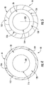
- Front edge 116 can move between the first position, as depicted in FIG. 4 , and the second position, as depicted in FIG. 5 .
- front edge 116 can move between the first position and the second position in a substantially uniform manner about the circumferential direction of the gas turbine engine 10.
- front edge 116 can move between the first position and second position such that annular inlet 20 is generally uniform around the circumferential direction of the gas turbine engine 10.
- front edge 116 could comprise a plurality of overlapping panels that can open or close to move between the first position and second position.
- front edge 116 that are moveable between the first position and second position in a generally uniform manner about the circumferential direction of gas turbine engine 10 can be used without departing from the scope or spirit of the present disclosure. Additionally, in some embodiments, front edge 116 can move to the one or more intermediate positions in a substantially uniform manner about the circumferential direction of the gas turbine engine 10.
- front edge 116 in the first position defines the first radius 120 and a first circumference 124.
- front edge 116 in the second position defines the second radius 122 and a second circumference 126.
- first radius 120 is greater than second radius 122 and first circumference 124 is greater than second circumference 126.
- front edge 116 and inner flowpath surface 114 together define a first area 128 of annular inlet 20.
- front edge 116 and inner flowpath surface 114 together define a second area 130 of annular inlet 20.
- first area 128 is greater than second area 130.
- front edge 116 in the first position will allow an increased first portion of air 60 to enter annular inlet 20 as compared to the first portion of air 60 that can enter annular inlet 20 when front edge 116 is in the second position. Additionally and/or alternatively, front edge 116 in the first position will allow first portion of air 60 to enter annular inlet 20 at a first airflow speed and front edge 116 in the second position will allow the first portion of air 60 to enter annular inlet 20 at a second airflow speed. The airflow speed of the first portion of air 60 in the second position is greater than the airflow speed of the first portion of air 60 in the first position. In another embodiment not shown in FIGS.
- front edge 116 can be adjusted to one or more intermediate positions such that the inlet area in the intermediate position is less than the first area 128 and greater than the second area 130.
- front edge 116 in the intermediate position will allow a first portion of air 60 to enter the engine airflow path 64 that is less than the first portion of air 60 in the first position and more than the first portion of air 60 in the second position.
- front edge 116 in the intermediate position will allow a first portion of air 60 to enter annular inlet 20 at an airflow speed that is less than the airflow speed of the first portion of air 60 in the second position and greater than the airflow speed of the first portion of air 60 in the first position.
- FIGS. 6 and 7 the same forward end of gas turbine engine 10 depicted in FIGS. 2 and 3 is shown according to additional example aspects of the present disclosure. Structures that are the same or similar to those shown in FIGS. 2 and 3 are referred to with the same reference numerals.
- translating inlet assembly 112 is located on the forward end of outer casing 18.
- core engine 16 can include an inner flowpath surface 114.
- Translating inlet assembly 112 can include a front edge 116 which can be moved by one or more actuators 118.
- a plurality of actuators 118 can be spaced about the circumferential direction of gas turbine engine 10 to move front edge 116.
- front edge 116 and inner flowpath surface 114 can define annular inlet 20, as shown in FIG. 1 .
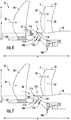
- front edge 116 can be moved at least partially along axial direction A between a first position and a second position.
- front edge 116 is in a first position such that annular inlet 20 has a first inlet area 128.
- front edge 116 is in a second position such that annular inlet 20 has a second inlet area 130.
- front edge 116 is in a first position such that front edge 116 defines a first radius 120.
- front edge 116 is in a second position such that front edge 116 defines a second radius 122.
- first radius 120 and second radius 122 are equal.
- first radius 120 can be different than second radius 122.
- first portion of air 60 enters core engine 16 by passing between front edge 116 and inner flowpath surface 114.
- front edge 116 in the first position allows an increased first portion of air 60 to enter engine flowpath 64 as compared to front edge 116 in the second position.
- front edge 116 in the first position will allow first portion of air 60 at a first airflow speed and front edge 116 in the second position will allow the first portion of air 60 at a second airflow speed.
- the airflow speed of the first portion of air 60 in the second position is greater than the airflow speed of the first portion of air 60 in the first position.
- front edge 116 can be moved to one or more intermediate positions such that the first portion of air 60 in the intermediate position is less than the first portion of air 60 in the first position and more than the first portion of air 60 in the second position. Additionally and/or alternatively, front edge 116 in the intermediate position will allow a first portion of air 60 at an airflow speed that is less than the airflow speed of the first portion of air 60 in the second position and greater than the airflow speed of the first portion of air 60 in the first position.
- front edge 116 can move between the first position, second position, and intermediate position in a substantially uniform manner about the circumferential direction of the gas turbine engine 10.
- front edge 116 can move along the axial direction between the first, second, and intermediate positions such that annular inlet 20 is generally uniform around the circumferential direction of the gas turbine engine 10.
- front edge 116 could comprise a solid front edge configured to move along the axial direction A and maintain a fixed radius in the first, second, and intermediate positions.
- Other embodiments of front edge 116 that can move between the first, second, and intermediate positions in a generally uniform manner about the circumferential direction of gas turbine engine 10 can be used without departing from the scope or spirit of the present disclosure.
- front edge 116 can be moved in response to a signal from a control device, such as, for instance, control device 1000 depicted in FIG. 10 .
- a control device such as, for instance, control device 1000 depicted in FIG. 10 .
- front edge 116 can be moved in response to a control signal sent to one or more actuators 118 that controls the one or more actuators 118 to move front edge 116 to a particular setpoint, such as the first, second, or intermediate positions.
- the amount and/or speed of airflow that flows through engine airflow path 64 can be varied, and the performance of annular inlet 20 can be varied to match the airflow demand of the LP compressor 22.
- translating inlet assembly 112 can be controlled to move front edge 116 to move between the first, second, and intermediate positions to allow an increased or decreased first portion of air 60 to flow into the engine airflow path 64 or an increased or decreased airflow speed of first portion of air 60 to adjust airflow distortion to improve the operability of gas turbine engine 10 or increase the stall margin of LP compressor 22.
- adjusting the airflow distortion may include adjusting an inlet airflow distortion and/or adjusting an airflow or airflow speed mismatch between LP compressor 22 and HP compressor 24.
- front edge 116 of translating inlet assembly 112 can be configured to be controlled to adjust airflow distortion in engine airflow path 64.
- a control device such as control device 1000 shown in FIG. 10
- the control device can then control translating inlet assembly 112 to adjust the airflow distortion, by, for example, sending a control signal to one or more actuators 118 to move front edge 116 between the first, second, and intermediate positions to increase or decrease the first portion of air 60 or to increase or decrease an airflow speed of first portion of air 60 flowing into the engine airflow path 64.
- airflow distortion in a gas turbine engine can be adjusted, and moreover, reduced, thereby improving operability of the gas turbine engine.
- one or more pressure sensor devices can be located at least partially within engine airflow path 64.
- the one or more pressure sensor devices can be at least partially integrated into one or more members in the engine airflow path 64, such as an instrumented guide vane 400 as shown in FIGS. 8 and 9 .
- the one or more pressure sensor devices can be integrated into inlet guide vane 100 or strut 102.
- Other pressure sensor devices can also be used without departing from the scope or spirit of the present disclosure. Using measurements obtained by the one or more pressure sensor devices, an airflow distortion assessment can be determined.
- a plurality of pressure sensing devices can be spaced about the circumferential direction of gas turbine engine 10.
- gas turbine engine 10 can include a plurality of instrumented guide vanes 400 spaced about the circumferential direction of gas turbine engine 10 as depicted in FIG. 8 .
- an airflow distortion assessment can be made. For example, a non-uniform pressure profile across the circumferential direction of the engine airflow path could indicate that airflow distortion is present in a particular area of engine airflow path 64.
- the one or more pressure sensor devices can be used at least in part for determining an airflow and/or airflow speed mismatch between two compressors, such as an LP compressor 22 and HP compressor 24.
- One or more actuators 118 then be controlled to move front edge 116 of translating inlet assembly 112 to increase or decrease the first portion of air 60 flowing into engine airflow path 64, thereby adjusting, and further, reducing the airflow distortion.
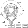
- FIG. 8 a schematic, axial view of an array of individual guide vanes 104 in the example gas turbine engine 10 of FIG. 1 is shown.
- a plurality of individual guide vanes 104 are configured in a circumferential array located in the engine airflow path 64 upstream of the LP Compressor 22.
- five instrumented guide vanes 400 are included in the array of individual guide vanes 104.
- each individual instrumented guide vane 400 is configured with a pressure sensing device. As shown in FIG.
- the pressure sensing device includes one or more taps 202 extending through the individual instrumented guide vane 400 and one or more local transducers 204 configured to measure an air pressure from the one or more taps 202.
- the pressure sensing device can be any suitable device configured to sense pressure without departing from the scope or spirit of the present disclosure.
- one or more pressure sensor devices such as an array of instrumented guide vanes depicted in FIG. 8 , can be used for obtaining one or more measurements to determine an airflow distortion condition in the engine airflow path, such as an inlet airflow distortion.
- Additional pressure sensor devices not depicted can also be used for obtaining measurements to determine other airflow distortion conditions, such as an airflow and/or airflow speed mismatch between two compressors, such as a LP compressor 22 and HP compressor 24 (see e.g., FIG. 1 ).
- local transducer 204 is configured to send data indicative of an air pressure to a digital communication bus 206.
- Digital communication bus 206 then sends the data indicative of an air pressure to controller 208.
- controller 208 can be a control device programmed to perform operations, such as control device 1000 depicted in FIG. 10 .
- Controller 208 can control various actuators based on the data indicative of an air pressure, such as one or more actuators 118 of a translating inlet assembly 112.
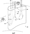
- FIG. 9 is a schematic of an individual instrumented guide vane 400 for an example gas turbine engine according to example embodiments of the present disclosure.
- Instrumented guide vane 400 can be a variable guide vane 104 or a stationary guide vane 100.
- instrumented guide vane 400 can be configured in a nonsymmetrical airfoil shape generally having a "tear drop" shape with a leading edge 410, a pressure side 420, and a suction side 430.
- the instrumented guide vane 400 may instead define any other suitable symmetrical or nonsymmetrical shape or configuration.
- leading edge 410 can be configured within engine airflow path 64 such that first portion of air 60 flowing downstream of annular inlet 20 first comes into contact with leading edge 410 before flowing over pressure side 420 and suction side 430 and continuing into LP compressor 22.
- leading edge taps 412, pressure side taps 422 and/or suction side taps 432 are integrated into instrumented guide vane 400.
- the leading edge taps 412, pressure side taps 422, and suction side taps 432 are depicted in phantom.
- two leading edge inlets 414 are spaced radially along leading edge 410 to allow air from an engine airflow, such as first portion of air 60, to enter leading edge inlet 414 and flow through leading edge tap 412 to a local transducer 204 (not shown in FIG. 9 ).
- a single leading edge inlet 414 and leading edge tap 412 can be integrated into leading edge 410.
- three or more leading edge inlets 414 and leading edge taps 412 can be integrated into leading edge 410.
- two pressure side inlets 424 are spaced axially along pressure side 420 to allow an engine airflow, such as air from first portion of air 60, to enter pressure side inlet 424 and flow through pressure side tap 422 to a local transducer 204 (not shown in FIG. 9 ).
- a single pressure side inlet 424 and pressure side tap 422 are integrated into pressure side 420.
- three or more pressure side inlets 424 and pressure side taps 422 are integrated into pressure side 420.
- two suction side inlets 434 are spaced axially along suction side 430 to allow air from an engine airflow, such as first portion of air 60, to enter suction side inlet 434 and flow through suction side tap 432 to a local transducer 204 (not shown in FIG. 9 ).
- the suction side inlets 434 are depicted in phantom.
- a single suction side inlet 434 and suction side tap 432 are integrated into suction side 430.
- three or more suction side inlets 434 and suction side taps 432 are integrated into suction side 430.
- local transducer 204 can be configured to provide measurements of a pressure differential between a pressure side tap 422 and a suction side tap 432.
- local transducer 204 can be configured to provide measurements of absolute pressures from a pressure side tap 422 and a suction side tap 432.
- FIG. 10 depicts an example control device used in a control system according to example embodiments of the present disclosure.
- the control device(s) 1000 can include one or more processors 1012 and one or more memory devices 1014.
- the one or more processors 1012 can include any suitable processing device, such as a microprocessor, microcontroller, integrated circuit, logic device, or other suitable processing device.
- the one or more memory devices 1014 can include one or more computer-readable media, including, but not limited to, non-transitory computer-readable media, RAM, ROM, hard drives, flash drives, or other memory devices.
- the one or more memory devices 1014 can store information accessible by the one or more processors 1012, including computer-readable instructions 1016 that can be executed by the one or more processors 1012.
- the instructions 1016 can be any set of instructions that when executed by the one or more processors 1012, cause the one or more processors 1012 to perform operations.
- the instructions 1016 can be implemented in software written in any suitable programming language or can be implemented in hardware.
- the instructions 1016 can be executed by the one or more processors 1012 to cause the one or more processors 1012 to perform operations, such as the operations for controlling a translating inlet assembly to adjust airflow distortion in a gas turbine engine as described with reference to FIG. 11 .
- the memory devices 1014 can further store data 1018 that can be accessed by the processors 1012.
- the data 1018 can include, for instance, operating parameters, pressure measurements obtained from the engine airflow path, and other data.
- the data 1018 can also include data associated with models and algorithms used to perform the example methods according to example aspects of the present disclosure, such as models and algorithms for determining a distortion condition.
- the control device(s) 1000 can further include a communications interface 1020.
- the communications interface 1020 can be configured to communicate with aircraft systems over a communication network 1040.
- the communications interface 1020 can receive data indicative of a pressure obtained by a pressure sensing device, such as a tap 202 and local transducer 204.
- the communications interface 1020 can provide control commands to an engine control system 1050 that has one or more actuators to control various components of the gas turbine engine 10, such as, but not limited to, an actuator 118 of a translating inlet assembly 112.
- the communications interface 1020 can include any suitable components for interfacing with one more other devices, including for example, transmitters, receivers, ports, controllers, antennas, or other suitable components.
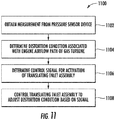
- FIG. 11 a flow diagram of an example method (1100) according to example embodiments of the present disclosure is depicted.
- FIG. 11 can be implemented by one or more control devices, such as the control device 1000 depicted in FIG. 10 .
- FIG. 11 depicts steps performed in a particular order for purposes of illustration and discussion. Those of ordinary skill in the art, using the disclosures provided herein, will understand that the various steps of any of the methods disclosed herein can be modified, adapted, expanded, rearranged and/or omitted in various ways without deviating from the scope of the present disclosure.
- the method can include obtaining one or more measurements from one or more pressure sensor devices.
- the one or more measurements can be obtained by, for example, a local transducer 204 operatively connected to an instrumented guide vane 400 as shown in FIGS. 8 and 9 .
- the one or more measurements can be obtained from any other suitable pressure sensor device.
- the method can include determining a distortion condition associated with the engine airflow path of a gas turbine engine from the one or more measurements. For example, using the one or more measurements, a distortion condition can be determined, such as a local flow disruption in the engine airflow path 64 of the gas turbine engine 10 that causes portions of the LP compressor 22 to be at or below pressures sufficient to cause stall conditions.
- the method can include determining a control signal for activation of a translating inlet assembly based at least in part on the distortion condition assessment. For example, a set point can be determined for a translating inlet assembly 112 to increase the airflow through the translating inlet assembly 112 in order to energize an area of the engine airflow path 64 that is experiencing a local flow disruption. A control signal representing the determined set point of the translating inlet assembly 112 can then be sent to one or more actuators 118 in order to adjust the translating inlet assembly 112.
- the method can include controlling the translating inlet assembly 112 to adjust the distortion condition based on the control signal.
- one or more actuators 122 can move front edge 116 of translating inlet assembly 112 based on the control signal.
- the translating inlet assembly 112 can be then controlled to move to the determined set point to adjust the airflow distortion. In this way, a translating inlet assembly 112 can adjust the airflow distortion associated with the gas turbine engine.
Landscapes
- Engineering & Computer Science (AREA)
- Chemical & Material Sciences (AREA)
- Combustion & Propulsion (AREA)
- Mechanical Engineering (AREA)
- General Engineering & Computer Science (AREA)
- Physics & Mathematics (AREA)
- Fluid Mechanics (AREA)
- Geometry (AREA)
- Structures Of Non-Positive Displacement Pumps (AREA)
- Control Of Turbines (AREA)
Abstract
Description
- The present subject matter relates generally to gas turbine engines and more particularly to a translating inlet for adjusting airflow distortion in a gas turbine engine.
- A gas turbine engine generally includes a core having, in serial flow order, a compressor section, a combustion section, a turbine section, and an exhaust section. During operation, an engine airflow is provided to an inlet of the compressor section where one or more axial compressors progressively compress the air until it reaches the combustion section. Fuel is mixed with the compressed air and burned within the combustion section to provide combustion gases. The combustion gases are routed from the combustion section to the turbine section. The flow of combustion gasses through the turbine section drives the compressor section and is then routed through the exhaust section, e.g., to atmosphere.
- During operation, the gas turbine engine may encounter airflow distortion in the engine airflow path upstream of the compressor section, such as a circumferential or local flow disruption due to the angle of attack of the gas turbine engine, a cross wind, or any other inlet anomaly. Airflow distortion can be so uneven during operation as to put portions of the compressor section at or below proper stall pressure ratios. In many cases, sufficient stall margin should be maintained in the compressor section in order to prevent stall conditions from occurring during operation of the gas turbine engine.
- One approach to maintaining a desired stall margin in a gas turbine engine is to close the variable guide vanes at the inlet to the compressor section, thereby reducing air flow and pressure in the compressor section below a pressure sufficient to cause stall conditions. However, closing the variable guide vanes can decrease the overall efficiency of the gas turbine engine.
- Aspects and advantages of the invention will be set forth in part in the following description, or may be obvious from the description, or may be learned through practice of the invention.
- One example aspect of the present disclosure is directed to a core engine of a gas turbine engine. The core engine can include a compressor section, a combustion section, and a turbine section in series flow and defining at least in part an engine airflow path for the gas turbine engine. The core engine can also include an inner flowpath surface positioned at least partially within the compressor section and defining at least in part the engine airflow path. The core engine can also include a core casing at least partially enclosing the compressor section and defining a forward end. The core casing can include a translating inlet assembly at the forward end. The translating inlet assembly and inner flowpath surface can together define an inlet to the compressor section. The translating inlet assembly can be moveable between a first position defining a first inlet area at the inlet and a second position defining a second inlet area at the inlet, with the first inlet area being greater than the second inlet area.
- Another example aspect of the present disclosure is directed to a method for adjusting airflow distortion in a gas turbine engine. The gas turbine engine can include a compressor section, a combustion section, and a turbine section in series flow. The compressor section, combustion section, and turbine section can define at least in part an engine airflow path. The gas turbine engine can include an inner flow path surface positioned at least partially within the compressor section and defining at least in part the engine airflow path. The gas turbine engine can include a core casing at least partially enclosing the compressor section and defining a forward end. The method includes determining, by one or more control devices, an airflow distortion condition associated with the engine airflow path. The method can also include controlling, by the one or more control devices, a translating inlet assembly to adjust the airflow distortion condition of the gas turbine engine. The core casing can include the translating inlet assembly at the forward end. The translating inlet assembly and inner flow path surface can together define an inlet to the compressor section. The translating inlet assembly can be moveable between a first position defining a first inlet area and a second position defining a second inlet area, with the first inlet area being greater than the second inlet area.
- Other example aspects of the present disclosure are directed to gas turbine engines, devices, apparatus, and other systems configured to adjust airflow distortion in the airflow path of a gas turbine engine. Variations and modifications can be made to these example aspects of the present disclosure.
- These and other features, aspects and advantages of various examples will become better understood with reference to the following description and appended claims. The accompanying drawings, which are incorporated in and constitute a part of this specification, illustrate aspects of the present disclosure and, together with the description, serve to explain the related principles.
- A full and enabling disclosure of the present invention, including the best mode thereof, directed to one of ordinary skill in the art, is set forth in the specification, which makes reference to the appended figures, in which:
-
FIG. 1 is a schematic, cross-sectional view of a gas turbine engine according to example embodiments of the present subject matter. -
FIG. 2 is schematic, cross-sectional view of a forward end of an example gas turbine engine according to example embodiments of the present disclosure. -
FIG. 3 is schematic, cross-sectional view of a forward end of an example gas turbine engine according to example embodiments of the present disclosure. -
FIG. 4 is a schematic, axial view of a forward end of an example gas turbine engine according to example embodiments of the present disclosure. -
FIG. 5 is a schematic, axial view of a forward end of an example gas turbine engine according to example embodiments of the present disclosure. -
FIG. 6 is schematic, cross-sectional view of a forward end of an example gas turbine engine according to example embodiments of the present disclosure. -
FIG. 7 is schematic, cross-sectional view of a forward end of an example gas turbine engine according to example embodiments of the present disclosure. -
FIG. 8 is a schematic, axial view of an array of instrumented guide vanes in an example gas turbine engine according to example embodiments of the present disclosure. -
FIG. 9 is a schematic of an individual instrumented guide vane in an example gas turbine engine according to example embodiments of the present disclosure. -
FIG. 10 depicts an example control device used in a control system according to example embodiments of the present disclosure. -
FIG. 11 depicts a flow diagram of an example method according to example embodiments of the present disclosure. - Reference now will be made in detail to embodiments of the present disclosure, one or more examples of which are illustrated in the drawings. Each example is provided by way of explanation of the invention, not limitation of the invention. In fact, it will be apparent to those skilled in the art that various modifications and variations can be made in the present invention without departing from the scope or spirit of the present disclosure. For instance, features illustrated or described as part of one embodiment can be used with another embodiment to yield a still further embodiment. Thus, it is intended that the present invention covers such modifications and variations as come within the scope of the appended claims and their equivalents.
- Example aspects of the present disclosure are directed to adjusting airflow distortion in a gas turbine engine in real-time. Airflow distortion can be so uneven during operation of the gas turbine engine as to put portions of the compressor section at or below proper stall pressure ratios, thereby reducing the operability of the gas turbine engine. Increased stall margin headroom can therefore be necessary to account for airflow distortion.
- The gas turbine engine and method according to example aspects of the present disclosure can increase the operability of the aircraft's gas turbine engine by making a real-time assessment of airflow distortion in the engine airflow path of the gas turbine engine and adjusting the airflow distortion in the engine airflow path by operating a translating inlet assembly to vary the amount and/or speed of airflow into the engine airflow path of the gas turbine engine based on the airflow distortion assessment. Real-time pressure measurements obtained from the engine airflow path can be used to make an assessment of airflow distortion conditions in the gas turbine engine. Airflow distortion in the engine airflow path can then be adjusted by opening or closing the translating inlet assembly to increase or decrease the amount of airflow and/or airflow speed into the engine airflow path. By adjusting the airflow distortion in the engine airflow path, the operability of the gas turbine engine can be improved. According to particular aspects of the present disclosure, a translating inlet assembly can be used to vary the amount and/or speed of airflow entering the engine airflow path in a gas turbine engine in response to airflow distortion in the engine airflow path. The gas turbine engine can include a compressor section, a combustion section, and a turbine section series flow and enclosed by a casing. The gas turbine engine can include a translating inlet assembly at a forward end of the casing. An engine airflow can enter the gas turbine engine through an inlet to the compressor section between a front edge of the translating inlet assembly and an inner flowpath surface. The engine airflow can then flow through the engine airflow path of the gas turbine engine. The front edge of the translating inlet assembly can be configured to move between a first position and a second position in order to vary the area of the inlet to the compressor section. For example, in an embodiment, the front edge of the translating inlet assembly can move generally along an axial direction in order to increase or decrease the inlet area about the circumference of the inlet of the compressor section of the gas turbine engine. In another embodiment, the front edge of the translating inlet assembly can move between a first position and a second position such that the front edge of the translating inlet assembly translates at least partially along a radial direction to increase or decrease the inlet area. In an embodiment, the translating inlet assembly can move between the first position and the second position in a generally uniform manner about the circumference of the gas turbine engine such that the inlet area of the compressor section is generally uniform about the entire circumference of the inlet. In another embodiment, the translating inlet assembly can move to one or more intermediate positions such that the inlet area in the one or more intermediate positions is less than the inlet area in the first position and more than the inlet area in the second position.
- In an embodiment, the translating inlet assembly can be configured to be controlled to move between positions in response to airflow distortion. For example, in one embodiment, one or more pressure sensing devices can be integrated into various components that extend into the engine airflow path of the gas turbine engine. A distortion condition assessment can be made based on the real-time pressure measurements obtained from the pressure sensing devices. For example, a non-uniform pressure profile across the engine airflow path can indicate that airflow distortion is present in the engine airflow path. The translating inlet assembly can then be controlled to adjust the airflow distortion associated with the engine airflow path. For example, the translating inlet assembly can be controlled to increase or reduce the inlet area of the compressor section to allow or restrict airflow into the engine airflow path, thereby reducing the airflow distortion.
- In this way, the gas turbine engine and method according to example aspects of the present disclosure can have a beneficial effect of adjusting the airflow distortion of the gas turbine engine based on real-time airflow distortion conditions. Further, this can allow an increase in the operability of the gas turbine engine by increasing the stall margin headroom available for operational safety.
- Reference will now be made in detail to present embodiments of the invention, one or more examples of which are illustrated in the accompanying drawings. The detailed description uses numerical and letter designations to refer to features in the drawings. Like or similar designations in the drawings and description have been used to refer to like or similar parts of the invention. As used herein, the terms "first", "second", and "third" may be used interchangeably to distinguish one component from another and are not intended to signify location or importance of the individual components. The terms "upstream" and "downstream" refer to the relative direction with respect to fluid flow in a fluid pathway. For example, "upstream" refers to the direction from which the fluid flows, and "downstream" refers to the direction to which the fluid flows.
- Referring now to the drawings, wherein identical numerals indicate the same elements throughout the figures,
FIG. 1 is a schematic cross-sectional view of a gas turbine engine in accordance with an example embodiment of the present disclosure. More particularly, for the embodiment ofFIG. 1 , the gas turbine engine is a high-bypassturbofan jet engine 10, referred to herein as "gas turbine engine 10." Example aspects of the present disclosure can be used with other suitable gas turbine engines without deviating from the scope of the present disclosure. - As shown in
FIG. 1 , thegas turbine engine 10 defines an axial direction A (extending parallel to alongitudinal centerline 12 provided for reference) and a radial direction R. Thegas turbine engine 10 also defines a circumferential direction (not depicted). In general, thegas turbine engine 10 includes afan section 14 and acore engine 16, thefan section 14 configured in mechanical communication and positioned in flow communication with thecore engine 16. - The
example core engine 16 depicted generally includes a substantially tubularouter casing 18 which defines a forward end that includes a translatinginlet assembly 112. Translatinginlet assembly 112 and aninner flowpath surface 114 together define anannular inlet 20. Theouter casing 18 encases, in serial flow relationship, a compressor section including a booster or low pressure (LP)compressor 22 and a high pressure (HP)compressor 24; acombustion section 26; a turbine section including a high pressure (HP)turbine 28 and a low pressure (LP)turbine 30; and a jetexhaust nozzle section 32. A high pressure (HP) shaft orspool 34 drivingly connects theHP turbine 28 to theHP compressor 24. A low pressure (LP) shaft orspool 36 drivingly connects theLP turbine 30 to theLP compressor 22. - Additionally, for the embodiment depicted, the
fan section 14 includes avariable pitch fan 38 having a plurality offan blades 40 coupled to adisk 42 in a spaced apart manner. As depicted, thefan blades 40 extend outwardly from thedisk 42 generally along the radial direction R. Thefan blades 40 anddisk 42 are together rotatable about thelongitudinal centerline 12 byLP shaft 36 across apower gear box 44. Thepower gear box 44 includes a plurality of gears for adjusting the rotational speed of theLP shaft 36. Additionally, for the embodiment depicted, thedisk 42 of thevariable pitch fan 38 is covered by arotatable front hub 46 aerodynamically contoured to promote an airflow through the plurality offan blades 40. - Referring still to
FIG. 1 , the examplegas turbine engine 10 additionally includes a plurality of circumferentially-spaced outlet guide vanes 50. The plurality ofoutlet guide vanes 50 are positioned downstream from thefan 38 along the axial direction A and extend outwardly from theouter casing 18 of thecore engine 16 generally along the radial direction R. Eachoutlet guide vane 50 defines a center of pressure 52 (shown inFIG. 2 ) and a pitch axis P extending substantially parallel to the radial direction R. Notably, for the embodiment depicted, thegas turbine engine 10 does not include any outer casing enclosing thefan section 14 and/or outlet guide vanes 50. Accordingly, for the embodiment depicted, thegas turbine engine 10 may be referred to as an un-ducted single fangas turbine engine 10. - For the example
gas turbine engine 10 depicted, thefan section 14, or more particularly, the rotation of thefan blades 40 of thefan section 14, provides a majority of the propulsive thrust of thegas turbine engine 10. Additionally, the plurality ofoutlet guide vanes 50 are provided to increase an efficiency of thefan section 14 as well as to provide other benefits, such as, for example, decreasing an amount of noise generated by thegas turbine engine 10. - During operation of the
gas turbine engine 10, a volume ofair 56 passes over the plurality ofblades 40 of thefan section 14. A first portion of the volume ofair 56, i.e., the first portion ofair 60, is directed or routed throughannular inlet 20 into anengine airflow path 64 extending through the compressor section, thecombustion section 26, the turbine section, and theexhaust section 32. The first portion ofair 60 may also be referred to as an engine airflow. Additionally, a second portion of the volume ofair 56, e.g., a second portion ofair 62, flows around thecore engine 16, bypassing thecore engine 16. The second portion ofair 62 may also be referred to as a bypass airflow. The ratio between the second portion ofair 62 and the first portion ofair 60 is commonly known as a bypass ratio. - Referring still to
FIG. 1 , the pressure of the first portion ofair 60 is increased as it is routed through theLP compressor 22 and subsequently through theHP compressor 24. The compressed first portion ofair 60 is then provided to thecombustion section 26, where it is mixed with fuel and burned to providecombustion gases 74. Thecombustion gases 74 are routed through theHP turbine 28 where a portion of thermal and/or kinetic energy from thecombustion gases 74 is extracted via sequential stages of HPturbine stator vanes 76 that are coupled to theouter casing 18 and HPturbine rotor blades 78 that are coupled to the HP shaft orspool 34, thus causing the HP shaft orspool 34 to rotate, thereby supporting operation of theHP compressor 24. Thecombustion gases 74 are then routed through theLP turbine 30 where a second portion of thermal and kinetic energy is extracted from thecombustion gases 74 via sequential stages of LPturbine stator vanes 80 that are coupled to theouter casing 18 and LPturbine rotor blades 82 that are coupled to the LP shaft orspool 36, thus causing the LP shaft orspool 36 to rotate, thereby supporting operation of theLP compressor 22 and/or rotation of thefan 38. Thecombustion gases 74 are subsequently routed through the jetexhaust nozzle section 32 of thecore engine 16 to provide propulsive thrust to supplement propulsive thrust provided by thefan section 14. - Referring still to
FIG. 1 , downstream of anannular inlet 20 is one or more inlet guide vanes 100. In certain example embodiments,inlet guide vane 100 may be configured to open or close, thereby restricting the flow of the first portion ofair 60 into theengine airflow path 64 extending through the compressor section. In certain example embodiments,inlet guide vane 100 can be an instrumentedguide vane 400 according to example embodiments of the present disclosure as depicted, for instance, inFIGS. 8 and9 . - Downstream of
inlet guide vane 100 is one ormore struts 102 configured to mechanically coupleouter casing 18 to thecore engine 16.Strut 102 extends into theengine airflow path 64 where first portion ofair 60 flows overstrut 102. In certain example embodiments, strut 102 is configured to obtain pressure measurements. Downstream ofstrut 102 is one or more variable guide vanes 104.Variable guide vanes 104 are configured to open or close, thereby restricting the flow of the first portion ofair 60 into theengine airflow path 64 extending through the compressor section. In certain example embodiments,variable guide vane 104 can be an instrumentedvariable guide vane 400 according to example embodiments of the present disclosure as shown, for instance, inFIGS. 8 and9 . - Referring now to
FIGS. 2 and 3 , a close-up, cross-sectional view of the forward end of the examplegas turbine engine 10 ofFIG. 1 according to example aspects of the present disclosure is shown. As shown, thegas turbine engine 10 includes at least onecontrol mechanism 106 configured to adjust avariable guide vane 104. In certain example embodiments, thegas turbine engine 10 may include a plurality ofcontrol mechanisms 106, eachindividual control mechanism 106 configured to adjust an individualvariable guide vane 104 or other member of the airflow path. - Referring still to
FIGS. 2 and 3 , translatinginlet assembly 112 is located on the forward end ofouter casing 18. As shown inFIGS. 2 and 3 ,core engine 16 can include aninner flowpath surface 114. Translatinginlet assembly 112 can include afront edge 116 which can be moved by one ormore actuators 118. In an embodiment, a plurality ofactuators 118 can be spaced about the circumferential direction ofgas turbine engine 10 to movefront edge 116. Together,front edge 116 andinner flowpath surface 114 can defineannular inlet 20, as shown inFIG. 1 . - As illustrated in
FIGS. 2 and 3 , in some embodiments,front edge 116 can be moved at least partially along radial direction R between a first position and a second position. For example, as shown inFIG. 2 ,front edge 116 is in a first position such thatfront edge 116 defines afirst radius 120. As shown inFIG. 3 ,front edge 116 is in a second position such thatfront edge 116 defines asecond radius 122. As depicted inFIGS. 2 and 3 ,first radius 120 is greater thansecond radius 122. - As depicted in
FIGS. 2 and 3 , first portion ofair 60 enterscore engine 16 by passing betweenfront edge 116 andinner flowpath surface 114. As depicted inFIGS. 2 and 3 ,front edge 116 in the first position allows an increased first portion ofair 60 to enterengine flowpath 64 as compared tofront edge 116 in the second position. In another embodiment not shown inFIGS. 2 and 3 ,front edge 116 can be moved to one or more intermediate positions such that the first portion ofair 60 in the intermediate position is less than the first portion ofair 60 in the first position and more than the first portion ofair 60 in the second position. - In an example embodiment,
front edge 116 can be moved in response to a signal from a control device, such as, for instance,control device 1000 depicted inFIG. 10 . For example, in an embodiment,front edge 116 can be moved in response to a control signal sent to one ormore actuators 118 that controls the one ormore actuators 118 to movefront edge 116 to a particular setpoint, such as the first, second, or intermediate positions. In this way, the amount of airflow and/or the speed of airflow that flows throughengine airflow path 64 can be varied, thereby allowing the performance ofannular inlet 20 to be varied to match the airflow demand of theLP compressor 22. In an embodiment, translatinginlet assembly 112 can be controlled to movefront edge 116 to move between the first, second, and intermediate positions to allow the performance ofannular inlet 20 to be varied to adjust airflow distortion to improve the operability ofgas turbine engine 10, or increase the stall margin ofLP compressor 22. For example, in certain embodiments, adjusting the airflow distortion may include adjusting an inlet airflow distortion and/or adjusting an airflow mismatch and/or airflow speed mismatch betweenLP compressor 22 andHP compressor 24. Airflow and/or airflow speed mismatch can occur because fans, such asvariable pitch fan 38 ingas turbine engine 10, may operate within a narrow speed range, which may be elevated. In such configurations, low pressure compressors, such asLP compressor 22, may operate at a similarly elevated speed because they are mechanically coupled to the variable pitch fan through a gearbox. In low power conditions, a low pressure compressor, such asLP compressor 22, may pump too much airflow for a high pressure compressor, such asHP compressor 24, to accept. - Referring now to
FIGS. 4 and 5 , a schematic, axial view of the example forward end of an examplegas turbine engine 10 depicted inFIGS. 2 and 3 is shown. As shown inFIGS. 4 and 5 ,gas turbine engine 10 includesouter casing 18.Outer casing 18 includes translatinginlet assembly 112 on a forward end. Translatinginlet assembly 112 can include afront edge 116.Gas turbine engine 10 can also include aninner flowpath surface 114. Together,front edge 116 andinner flowpath surface 114 can defineannular inlet 20. -
Front edge 116 can move between the first position, as depicted inFIG. 4 , and the second position, as depicted inFIG. 5 . In an embodiment,front edge 116 can move between the first position and the second position in a substantially uniform manner about the circumferential direction of thegas turbine engine 10. For example, as shown inFIGS. 4 and 5 ,front edge 116 can move between the first position and second position such thatannular inlet 20 is generally uniform around the circumferential direction of thegas turbine engine 10. For example,front edge 116 could comprise a plurality of overlapping panels that can open or close to move between the first position and second position. Other embodiments offront edge 116 that are moveable between the first position and second position in a generally uniform manner about the circumferential direction ofgas turbine engine 10 can be used without departing from the scope or spirit of the present disclosure. Additionally, in some embodiments,front edge 116 can move to the one or more intermediate positions in a substantially uniform manner about the circumferential direction of thegas turbine engine 10. - As depicted in
FIG. 4 ,front edge 116 in the first position defines thefirst radius 120 and afirst circumference 124. As depicted inFIG. 5 ,front edge 116 in the second position defines thesecond radius 122 and asecond circumference 126. As depicted inFIGS. 4 and 5 ,first radius 120 is greater thansecond radius 122 andfirst circumference 124 is greater thansecond circumference 126. Further, as depicted inFIG. 4 ,front edge 116 andinner flowpath surface 114 together define afirst area 128 ofannular inlet 20. As depicted inFIG. 5 ,front edge 116 andinner flowpath surface 114 together define asecond area 130 ofannular inlet 20. As depicted inFIGS. 4 and 5 ,first area 128 is greater thansecond area 130. During operation ofgas turbine engine 10,front edge 116 in the first position will allow an increased first portion ofair 60 to enterannular inlet 20 as compared to the first portion ofair 60 that can enterannular inlet 20 whenfront edge 116 is in the second position. Additionally and/or alternatively,front edge 116 in the first position will allow first portion ofair 60 to enterannular inlet 20 at a first airflow speed andfront edge 116 in the second position will allow the first portion ofair 60 to enterannular inlet 20 at a second airflow speed. The airflow speed of the first portion ofair 60 in the second position is greater than the airflow speed of the first portion ofair 60 in the first position. In another embodiment not shown inFIGS. 4 and 5 ,front edge 116 can be adjusted to one or more intermediate positions such that the inlet area in the intermediate position is less than thefirst area 128 and greater than thesecond area 130. During operation ofgas turbine engine 10,front edge 116 in the intermediate position will allow a first portion ofair 60 to enter theengine airflow path 64 that is less than the first portion ofair 60 in the first position and more than the first portion ofair 60 in the second position. Additionally and/or alternatively,front edge 116 in the intermediate position will allow a first portion ofair 60 to enterannular inlet 20 at an airflow speed that is less than the airflow speed of the first portion ofair 60 in the second position and greater than the airflow speed of the first portion ofair 60 in the first position. - Referring now to
FIGS. 6 and 7 , the same forward end ofgas turbine engine 10 depicted inFIGS. 2 and 3 is shown according to additional example aspects of the present disclosure. Structures that are the same or similar to those shown inFIGS. 2 and 3 are referred to with the same reference numerals. - As depicted in
FIGS. 6 and 7 , translatinginlet assembly 112 is located on the forward end ofouter casing 18. As shown inFIGS. 6 and 7 ,core engine 16 can include aninner flowpath surface 114. Translatinginlet assembly 112 can include afront edge 116 which can be moved by one ormore actuators 118. In an embodiment, a plurality ofactuators 118 can be spaced about the circumferential direction ofgas turbine engine 10 to movefront edge 116. Together,front edge 116 andinner flowpath surface 114 can defineannular inlet 20, as shown inFIG. 1 . - As illustrated in
FIGS. 6 and 7 , in some embodiments,front edge 116 can be moved at least partially along axial direction A between a first position and a second position. For example, as shown inFIG. 6 ,front edge 116 is in a first position such thatannular inlet 20 has afirst inlet area 128. As shown inFIG. 7 ,front edge 116 is in a second position such thatannular inlet 20 has asecond inlet area 130. As shown inFIG. 6 ,front edge 116 is in a first position such thatfront edge 116 defines afirst radius 120. As shown inFIG. 7 ,front edge 116 is in a second position such thatfront edge 116 defines asecond radius 122. As depicted inFIGS. 6 and 7 ,first radius 120 andsecond radius 122 are equal. In another embodiment,first radius 120 can be different thansecond radius 122. - As depicted in
FIGS. 6 and 7 , first portion ofair 60 enterscore engine 16 by passing betweenfront edge 116 andinner flowpath surface 114. As depicted inFIGS. 6 and 7 ,front edge 116 in the first position allows an increased first portion ofair 60 to enterengine flowpath 64 as compared tofront edge 116 in the second position. Additionally and/or alternatively,front edge 116 in the first position will allow first portion ofair 60 at a first airflow speed andfront edge 116 in the second position will allow the first portion ofair 60 at a second airflow speed. The airflow speed of the first portion ofair 60 in the second position is greater than the airflow speed of the first portion ofair 60 in the first position. In another embodiment not shown inFIGS. 6 and 7 ,front edge 116 can be moved to one or more intermediate positions such that the first portion ofair 60 in the intermediate position is less than the first portion ofair 60 in the first position and more than the first portion ofair 60 in the second position. Additionally and/or alternatively,front edge 116 in the intermediate position will allow a first portion ofair 60 at an airflow speed that is less than the airflow speed of the first portion ofair 60 in the second position and greater than the airflow speed of the first portion ofair 60 in the first position. - In an embodiment,
front edge 116 can move between the first position, second position, and intermediate position in a substantially uniform manner about the circumferential direction of thegas turbine engine 10. For example,front edge 116 can move along the axial direction between the first, second, and intermediate positions such thatannular inlet 20 is generally uniform around the circumferential direction of thegas turbine engine 10. For example,front edge 116 could comprise a solid front edge configured to move along the axial direction A and maintain a fixed radius in the first, second, and intermediate positions. Other embodiments offront edge 116 that can move between the first, second, and intermediate positions in a generally uniform manner about the circumferential direction ofgas turbine engine 10 can be used without departing from the scope or spirit of the present disclosure. - In an example embodiment,
front edge 116 can be moved in response to a signal from a control device, such as, for instance,control device 1000 depicted inFIG. 10 . For example, in an embodiment,front edge 116 can be moved in response to a control signal sent to one ormore actuators 118 that controls the one ormore actuators 118 to movefront edge 116 to a particular setpoint, such as the first, second, or intermediate positions. In this way, the amount and/or speed of airflow that flows throughengine airflow path 64 can be varied, and the performance ofannular inlet 20 can be varied to match the airflow demand of theLP compressor 22. In an embodiment, translatinginlet assembly 112 can be controlled to movefront edge 116 to move between the first, second, and intermediate positions to allow an increased or decreased first portion ofair 60 to flow into theengine airflow path 64 or an increased or decreased airflow speed of first portion ofair 60 to adjust airflow distortion to improve the operability ofgas turbine engine 10 or increase the stall margin ofLP compressor 22. For example, in certain embodiments, adjusting the airflow distortion may include adjusting an inlet airflow distortion and/or adjusting an airflow or airflow speed mismatch betweenLP compressor 22 andHP compressor 24. - Referring generally to
FIGS 2-7 , during operation ofgas turbine engine 10,front edge 116 of translatinginlet assembly 112 can be configured to be controlled to adjust airflow distortion inengine airflow path 64. For instance, a control device, such ascontrol device 1000 shown inFIG. 10 , can obtain measurements from one or more pressure sensor devices, and determine that an area of the engine airflow path is experiencing airflow distortion, such as airflow separation. The control device can then control translatinginlet assembly 112 to adjust the airflow distortion, by, for example, sending a control signal to one ormore actuators 118 to movefront edge 116 between the first, second, and intermediate positions to increase or decrease the first portion ofair 60 or to increase or decrease an airflow speed of first portion ofair 60 flowing into theengine airflow path 64. In this way, airflow distortion in a gas turbine engine can be adjusted, and moreover, reduced, thereby improving operability of the gas turbine engine. - In one embodiment, one or more pressure sensor devices can be located at least partially within
engine airflow path 64. In one embodiment, the one or more pressure sensor devices can be at least partially integrated into one or more members in theengine airflow path 64, such as an instrumentedguide vane 400 as shown inFIGS. 8 and9 . In another embodiment, the one or more pressure sensor devices can be integrated intoinlet guide vane 100 orstrut 102. Other pressure sensor devices can also be used without departing from the scope or spirit of the present disclosure. Using measurements obtained by the one or more pressure sensor devices, an airflow distortion assessment can be determined. - Additionally, in another example embodiment, a plurality of pressure sensing devices can be spaced about the circumferential direction of
gas turbine engine 10. For example,gas turbine engine 10 can include a plurality of instrumentedguide vanes 400 spaced about the circumferential direction ofgas turbine engine 10 as depicted inFIG. 8 . Using measurements obtained by the pressure sensor devices, an airflow distortion assessment can be made. For example, a non-uniform pressure profile across the circumferential direction of the engine airflow path could indicate that airflow distortion is present in a particular area ofengine airflow path 64. Additionally, the one or more pressure sensor devices can be used at least in part for determining an airflow and/or airflow speed mismatch between two compressors, such as anLP compressor 22 andHP compressor 24. One ormore actuators 118 then be controlled to movefront edge 116 of translatinginlet assembly 112 to increase or decrease the first portion ofair 60 flowing intoengine airflow path 64, thereby adjusting, and further, reducing the airflow distortion. - Referring now to
FIG. 8 , a schematic, axial view of an array ofindividual guide vanes 104 in the examplegas turbine engine 10 ofFIG. 1 is shown. As shown, a plurality ofindividual guide vanes 104 are configured in a circumferential array located in theengine airflow path 64 upstream of theLP Compressor 22. As depicted inFIG. 8 , five instrumentedguide vanes 400, as discussed below in greater detail with respect toFIG. 9 , are included in the array of individual guide vanes 104. As will be discussed in greater detail below with reference toFIG. 9 , each individual instrumentedguide vane 400 is configured with a pressure sensing device. As shown inFIG. 8 , the pressure sensing device includes one ormore taps 202 extending through the individual instrumentedguide vane 400 and one or morelocal transducers 204 configured to measure an air pressure from the one or more taps 202. However, it will be apparent to those skilled in the art will that the pressure sensing device can be any suitable device configured to sense pressure without departing from the scope or spirit of the present disclosure. According to example aspects of the present disclosure, one or more pressure sensor devices, such as an array of instrumented guide vanes depicted inFIG. 8 , can be used for obtaining one or more measurements to determine an airflow distortion condition in the engine airflow path, such as an inlet airflow distortion. Additional pressure sensor devices not depicted can also be used for obtaining measurements to determine other airflow distortion conditions, such as an airflow and/or airflow speed mismatch between two compressors, such as aLP compressor 22 and HP compressor 24 (see e.g.,FIG. 1 ). As shown inFIG. 8 ,local transducer 204 is configured to send data indicative of an air pressure to adigital communication bus 206.Digital communication bus 206 then sends the data indicative of an air pressure tocontroller 208. In an embodiment,controller 208 can be a control device programmed to perform operations, such ascontrol device 1000 depicted inFIG. 10 .Controller 208 can control various actuators based on the data indicative of an air pressure, such as one ormore actuators 118 of a translatinginlet assembly 112. -
FIG. 9 is a schematic of an individual instrumentedguide vane 400 for an example gas turbine engine according to example embodiments of the present disclosure. Instrumentedguide vane 400 can be avariable guide vane 104 or astationary guide vane 100. As depicted inFIG. 9 , instrumentedguide vane 400 can be configured in a nonsymmetrical airfoil shape generally having a "tear drop" shape with aleading edge 410, apressure side 420, and a suction side 430. However, in other example embodiments, the instrumentedguide vane 400 may instead define any other suitable symmetrical or nonsymmetrical shape or configuration. In some implementations, leadingedge 410 can be configured withinengine airflow path 64 such that first portion ofair 60 flowing downstream ofannular inlet 20 first comes into contact withleading edge 410 before flowing overpressure side 420 and suction side 430 and continuing intoLP compressor 22. - Referring still to
FIG. 9 , one or more leading edge taps 412, pressure side taps 422 and/or suction side taps 432 are integrated into instrumentedguide vane 400. The leading edge taps 412, pressure side taps 422, and suction side taps 432 are depicted in phantom. As depicted inFIG. 9 , two leadingedge inlets 414 are spaced radially along leadingedge 410 to allow air from an engine airflow, such as first portion ofair 60, to enter leadingedge inlet 414 and flow through leadingedge tap 412 to a local transducer 204 (not shown inFIG. 9 ). In another embodiment, a singleleading edge inlet 414 andleading edge tap 412 can be integrated intoleading edge 410. In another embodiment three or moreleading edge inlets 414 and leading edge taps 412 can be integrated intoleading edge 410. - Referring still to
FIG. 9 , twopressure side inlets 424 are spaced axially alongpressure side 420 to allow an engine airflow, such as air from first portion ofair 60, to enterpressure side inlet 424 and flow throughpressure side tap 422 to a local transducer 204 (not shown inFIG. 9 ). In another embodiment, a singlepressure side inlet 424 andpressure side tap 422 are integrated intopressure side 420. In another embodiment three or morepressure side inlets 424 and pressure side taps 422 are integrated intopressure side 420. - Referring still to
FIG. 9 , twosuction side inlets 434 are spaced axially along suction side 430 to allow air from an engine airflow, such as first portion ofair 60, to entersuction side inlet 434 and flow throughsuction side tap 432 to a local transducer 204 (not shown inFIG. 9 ). Thesuction side inlets 434 are depicted in phantom. In another embodiment a singlesuction side inlet 434 andsuction side tap 432 are integrated into suction side 430. In another embodiment, three or moresuction side inlets 434 and suction side taps 432 are integrated into suction side 430. - Referring still to
FIG. 9 , in an embodiment, local transducer 204 (not shown) can be configured to provide measurements of a pressure differential between apressure side tap 422 and asuction side tap 432. In another embodiment, local transducer 204 (not shown) can be configured to provide measurements of absolute pressures from apressure side tap 422 and asuction side tap 432. -
FIG. 10 depicts an example control device used in a control system according to example embodiments of the present disclosure. As shown, the control device(s) 1000 can include one ormore processors 1012 and one ormore memory devices 1014. The one ormore processors 1012 can include any suitable processing device, such as a microprocessor, microcontroller, integrated circuit, logic device, or other suitable processing device. The one ormore memory devices 1014 can include one or more computer-readable media, including, but not limited to, non-transitory computer-readable media, RAM, ROM, hard drives, flash drives, or other memory devices. - The one or
more memory devices 1014 can store information accessible by the one ormore processors 1012, including computer-readable instructions 1016 that can be executed by the one ormore processors 1012. Theinstructions 1016 can be any set of instructions that when executed by the one ormore processors 1012, cause the one ormore processors 1012 to perform operations. Theinstructions 1016 can be implemented in software written in any suitable programming language or can be implemented in hardware. In some embodiments, theinstructions 1016 can be executed by the one ormore processors 1012 to cause the one ormore processors 1012 to perform operations, such as the operations for controlling a translating inlet assembly to adjust airflow distortion in a gas turbine engine as described with reference toFIG. 11 . - Referring to
FIG. 10 , thememory devices 1014 can further storedata 1018 that can be accessed by theprocessors 1012. Thedata 1018 can include, for instance, operating parameters, pressure measurements obtained from the engine airflow path, and other data. Thedata 1018 can also include data associated with models and algorithms used to perform the example methods according to example aspects of the present disclosure, such as models and algorithms for determining a distortion condition. - The control device(s) 1000 can further include a
communications interface 1020. Thecommunications interface 1020 can be configured to communicate with aircraft systems over acommunication network 1040. For instance, thecommunications interface 1020 can receive data indicative of a pressure obtained by a pressure sensing device, such as atap 202 andlocal transducer 204. In one embodiment, thecommunications interface 1020 can provide control commands to anengine control system 1050 that has one or more actuators to control various components of thegas turbine engine 10, such as, but not limited to, anactuator 118 of a translatinginlet assembly 112. Thecommunications interface 1020 can include any suitable components for interfacing with one more other devices, including for example, transmitters, receivers, ports, controllers, antennas, or other suitable components. - The technology discussed herein makes computer-based systems, as well as actions taken and information sent to and from such systems. One of ordinary skill in the art will recognize that the inherent flexibility of computer-based systems allows for a great variety of possible configurations, combinations, and divisions of tasks and functionality between and among components. For instance, processes discussed herein may be implemented using a single computing device or multiple computing devices working in combination. Databases, memory, instructions, and applications may be implemented on a single system or distributed across multiple systems. Distributed components may operate sequentially or in parallel.
- Referring now to
FIG. 11 , a flow diagram of an example method (1100) according to example embodiments of the present disclosure is depicted.FIG. 11 can be implemented by one or more control devices, such as thecontrol device 1000 depicted inFIG. 10 . In addition,FIG. 11 depicts steps performed in a particular order for purposes of illustration and discussion. Those of ordinary skill in the art, using the disclosures provided herein, will understand that the various steps of any of the methods disclosed herein can be modified, adapted, expanded, rearranged and/or omitted in various ways without deviating from the scope of the present disclosure. - At (1102), the method can include obtaining one or more measurements from one or more pressure sensor devices. The one or more measurements can be obtained by, for example, a
local transducer 204 operatively connected to an instrumentedguide vane 400 as shown inFIGS. 8 and9 . Alternatively, the one or more measurements can be obtained from any other suitable pressure sensor device. - At (1104), the method can include determining a distortion condition associated with the engine airflow path of a gas turbine engine from the one or more measurements. For example, using the one or more measurements, a distortion condition can be determined, such as a local flow disruption in the
engine airflow path 64 of thegas turbine engine 10 that causes portions of theLP compressor 22 to be at or below pressures sufficient to cause stall conditions. - At (1106), the method can include determining a control signal for activation of a translating inlet assembly based at least in part on the distortion condition assessment. For example, a set point can be determined for a translating
inlet assembly 112 to increase the airflow through the translatinginlet assembly 112 in order to energize an area of theengine airflow path 64 that is experiencing a local flow disruption. A control signal representing the determined set point of the translatinginlet assembly 112 can then be sent to one ormore actuators 118 in order to adjust the translatinginlet assembly 112. - At (1108), the method can include controlling the translating
inlet assembly 112 to adjust the distortion condition based on the control signal. For example, one ormore actuators 122 can movefront edge 116 of translatinginlet assembly 112 based on the control signal. The translatinginlet assembly 112 can be then controlled to move to the determined set point to adjust the airflow distortion. In this way, a translatinginlet assembly 112 can adjust the airflow distortion associated with the gas turbine engine. - This written description uses examples to disclose the invention, including the best mode, and also to enable any person skilled in the art to practice the invention, including making and using any devices or systems and performing any incorporated methods. The patentable scope of the invention is defined by the claims, and may include other examples that occur to those skilled in the art. Such other examples are intended to be within the scope of the claims if they include structural elements that do not differ from the literal language of the claims, or if they include equivalent structural elements with insubstantial differences from the literal languages of the claims.
- Various aspects and embodiments of the present invention are defined by the following numbered clauses:
- 1. A core engine for a gas turbine engine, comprising:
- a compressor section, a combustion section, and a turbine section defining at least in part an engine airflow path for the core engine;
- an inner flowpath surface positioned at least partially within the compressor section and defining at least in part the engine airflow path;
- a core casing at least partially enclosing the compressor section and defining a forward end, the core casing comprising a translating inlet assembly at the forward end, the translating inlet assembly and inner flowpath surface together defining an inlet to the compressor section, the translating inlet assembly moveable between a first position defining a first inlet area at the inlet and a second position defining a second inlet area at the inlet, the first inlet area being greater than the second inlet area.
- 2. The core engine of clause 1, wherein the translating inlet assembly allows a first engine airflow at a first airflow speed into the engine airflow path in the first position, wherein the translating inlet assembly allows a second engine airflow at a second airflow speed into the engine airflow path in the second position, wherein at least one of the first engine airflow is greater than the second engine airflow or the first engine airflow speed is less than the second engine airflow speed.
- 3. The core engine of any preceding clause, wherein the translating inlet assembly is configured to be controlled based on an airflow distortion in the engine airflow path, and wherein the airflow distortion is an inlet airflow distortion.
- 4. The core engine of any preceding clause, wherein the compressor section includes a first compressor and a second compressor, wherein the translating inlet assembly is configured to be controlled based on an airflow distortion in the engine airflow path, and wherein the airflow distortion is an airflow mismatch between the first and second compressors.
- 5. The core engine of any preceding clause, wherein the translating inlet assembly is configured to be controlled based on an airflow distortion in the engine airflow path, the core engine further comprising:
- one or more pressure sensor devices located at least partially in the engine airflow path for obtaining one or more measurements associated with airflow distortion;
- wherein the translating inlet assembly is configured to be controlled based at least in part on signals from the one or more pressure sensor devices.
- 6. The core engine of any preceding clause, wherein the core engine defines a circumferential direction, wherein the translating inlet assembly is movable between the first position and the second position in a substantially uniform manner about the circumferential direction of the core engine.
- 7. The core engine of any preceding clause, wherein the translating inlet assembly is additionally movable to an intermediate position, wherein the intermediate position defines an intermediate inlet area, wherein the intermediate inlet area is less than the first inlet area and greater than the second inlet area.
- 8. The core engine of any preceding clause, wherein the translating inlet assembly is movable between the first, second, and intermediate positions based on signals from a controller to adjust an airflow distortion in the engine airflow path.
- 9. The core engine of any preceding clause, wherein the translating inlet assembly defines a front edge, wherein the core engine defines an axial direction, wherein the front edge of the translating inlet assembly moves between the first position and the second position at least partially along the axial direction.
- 10. The core engine of any preceding clause, wherein the translating inlet assembly defines a front edge, wherein the core engine defines a circumferential direction, wherein the front edge defines a first circumference in the first position, wherein the front edge defines a second circumference in the second position, wherein the second circumference is less than the first circumference.
- 11. A method for adjusting airflow distortion in a gas turbine engine on an aircraft, the gas turbine engine comprising a compressor section, a combustion section, and a turbine section in series flow, the compressor section, combustion section, and turbine section defining at least in part an engine airflow path, the gas turbine engine further comprising an inner flow path surface positioned at least partially within the compressor section and defining at least in part the engine airflow path, the gas turbine engine further comprising a core casing at least partially enclosing the compressor section and defining a forward end, the method comprising:
- determining, by one or more control devices, an airflow distortion condition associated with the engine airflow path; and
- controlling, by the one or more control devices, a translating inlet assembly to adjust the airflow distortion condition of the gas turbine engine, wherein the core casing comprises the translating inlet assembly at the forward end, the translating inlet assembly and inner flow path surface together defining an inlet to the compressor section, the translating inlet assembly moveable between a first position defining a first inlet area and a second position defining a second inlet area, the first inlet area being greater than the second inlet area.
- 12. The method of any preceding clause, wherein the translating inlet assembly is additionally movable to an intermediate position, wherein the intermediate position defines an intermediate inlet area, wherein the intermediate inlet area is less than the first inlet area and greater than the second inlet area.
- 13. The method of any preceding clause, wherein the translating inlet assembly allows a first engine airflow into the engine airflow path in the first position, wherein the translating inlet assembly allows a second engine airflow into the engine airflow path in the second position, wherein the translating inlet assembly allows an intermediate engine airflow into the engine airflow path in the intermediate position, wherein the intermediate engine airflow is less than the first engine airflow and greater than the second engine airflow.
- 14. The method of any preceding clause, wherein controlling the translating inlet assembly comprises moving the translating inlet assembly between the first, second, and intermediate positions.
- 15. The method of any preceding clause, wherein controlling the translating inlet assembly to adjust the airflow distortion condition comprises controlling the translating inlet assembly to reduce the airflow distortion condition.
- 16. The method of any preceding clause, wherein determining the airflow distortion condition associated with the engine airflow path comprises obtaining one or more measurements using one or more pressure sensor devices, wherein controlling the translating inlet assembly to adjust the airflow distortion comprises controlling the translating inlet assembly based at least in part on the one or more measurements obtained using the one or more pressure sensor devices.
- 17. The method of any preceding clause, wherein the translating inlet assembly defines a front edge, wherein the core engine defines an axial direction, wherein the front edge of the translating inlet assembly moves between the first position and the second position along the axial direction.
- 18. The method of any preceding clause, wherein the translating inlet assembly defines a front edge, wherein the core engine defines a circumferential direction, wherein the front edge defines a first circumference in the first position, wherein the front edge defines a second circumference in the second position, wherein the second circumference is less than the first circumference.
- 19. A gas turbine engine system for an aircraft comprising:
- a compressor section, a combustion section, and a turbine section defining at least in part an engine airflow path for the core engine;
- an inner flowpath surface positioned at least partially within the compressor section and defining at least in part the engine airflow path;
- a core casing at least partially enclosing the compressor section and defining a forward end, the core casing comprising a translating inlet assembly at the forward end, the translating inlet assembly and inner flowpath surface together defining an inlet to the compressor section, the translating inlet assembly moveable between a first position defining a first inlet area at the inlet and a second position defining a second inlet area at the inlet, the first inlet area being greater than the second inlet area; and
- a controller operably connected to the translating inlet assembly, the controller comprising one or more processors and one or more memory devices located on an aircraft, the one or more memory devices storing instructions that when executed by the one or more processors cause the one or more processors to perform operations, the operations comprising:
- determine an airflow distortion condition within the engine airflow path; and
- control the translating inlet assembly to adjust an airflow through the airflow passage to adjust the determined airflow distortion condition.
- 20. The gas turbine engine system of any preceding clause, wherein the core engine comprises one or more pressure sensor devices located at least partially in the engine airflow path configured to obtain measurements to determine the airflow distortion condition, wherein the translating inlet assembly is controlled by the controller based at least in part on measurements obtained by the one or more pressure sensors.
Claims (15)
- A core engine (16) for a gas turbine engine (10), comprising:a compressor section (22, 24), a combustion section (26), and a turbine section (28, 30) defining at least in part an engine airflow path (64) for the core engine(10);an inner flowpath surface (114) positioned at least partially within the compressor section (22, 24) and defining at least in part the engine airflow path (64);a core casing (18) at least partially enclosing the compressor section (22, 24) and defining a forward end, the core casing (18) comprising a translating inlet assembly (112) at the forward end, the translating inlet assembly (112) and inner flowpath surface (114) together defining an inlet (20) to the compressor section (22, 24), the translating inlet assembly (112) moveable between a first position defining a first inlet area (128) at the inlet (20) and a second position defining a second inlet area (130) at the inlet (20), the first inlet area (128) being greater than the second inlet area (130).
- The core engine (16) of claim 1, wherein the translating inlet assembly (112) allows a first engine airflow (60) at a first airflow speed into the engine airflow path (64) in the first position, wherein the translating inlet assembly (112) allows a second engine airflow (60) at a second airflow speed into the engine airflow path (64) in the second position, wherein at least one of the first engine airflow (60) is greater than the second engine airflow (60) or the first engine airflow (60) speed is less than the second engine airflow (60) speed.
- The core engine (16) of either of claim 1 or 2, wherein the translating inlet assembly (112) is configured to be controlled based on an airflow distortion in the engine airflow path (64), and wherein the airflow distortion is an inlet airflow distortion.
- The core engine (16) of any preceding claim, wherein the compressor section (22, 24) includes a first compressor and a second compressor, wherein the translating inlet assembly (112) is configured to be controlled based on an airflow distortion in the engine airflow path (64), and wherein the airflow distortion is an airflow mismatch between the first and second compressors.
- The core engine (16) of any preceding claim, wherein the translating inlet assembly (112) is configured to be controlled based on an airflow distortion in the engine airflow path (64), the core engine (16) further comprising:one or more pressure sensor devices located at least partially in the engine airflow path (64) for obtaining one or more measurements associated with airflow distortion;wherein the translating inlet assembly (112) is configured to be controlled based at least in part on signals from the one or more pressure sensor devices.
- The core engine (16) of any preceding claim, wherein the core engine (16) defines a circumferential direction, wherein the translating inlet assembly (112) is movable between the first position and the second position in a substantially uniform manner about the circumferential direction of the core engine (16).
- The core engine (16) of any preceding claim, wherein the translating inlet assembly (112) is additionally movable to an intermediate position, wherein the intermediate position defines an intermediate inlet area, wherein the intermediate inlet area is less than the first inlet area (128) and greater than the second inlet area (130).
- The core engine (16) of claim 7, wherein the translating inlet assembly (112) is movable between the first, second, and intermediate positions based on signals from a controller (208) to adjust an airflow distortion in the engine airflow path (64).
- The core engine (16) of any preceding claim, wherein the translating inlet assembly (112) defines a front edge (116), wherein the core engine (16) defines an axial direction, wherein the front edge (116) of the translating inlet assembly (112) moves between the first position and the second position at least partially along the axial direction.
- The core engine (16) of any preceding claim, wherein the translating inlet assembly (112) defines a front edge (116), wherein the core engine (16) defines a circumferential direction, wherein the front edge (16) defines a first circumference (124) in the first position, wherein the front edge (16) defines a second circumference (126) in the second position, wherein the second circumference (126) is less than the first circumference (124).
- A method (1100) for adjusting airflow distortion in a gas turbine engine (10) on an aircraft, the gas turbine engine (10) comprising a compressor section (22, 24), a combustion section (26), and a turbine section (28, 30) in series flow, the compressor section (22, 24), combustion section (26), and turbine section (28, 30) defining at least in part an engine airflow path (64), the gas turbine engine (10) further comprising an inner flowpath surface (114) positioned at least partially within the compressor section (22, 24) and defining at least in part the engine airflow path (64), the gas turbine engine (10) further comprising a core casing (18) at least partially enclosing the compressor section (22, 24) and defining a forward end, the method (1100) comprising:(at 1104) determining, by one or more control devices (1000), an airflow distortion condition associated with the engine airflow path (64); and(at 1108)controlling, by the one or more control devices (1000), a translating inlet assembly (112) to adjust the airflow distortion condition of the gas turbine engine (10), wherein the core casing (18) comprises the translating inlet assembly (112) at the forward end, the translating inlet assembly (112) and inner flow path surface (114) together defining an inlet (20) to the compressor section (22, 24), the translating inlet assembly (112) moveable between a first position defining a first inlet area (128) and a second position defining a second inlet area (130), the first inlet area (128) being greater than the second inlet area (130).
- The method (1100) of claim 11, wherein the translating inlet assembly (112) is additionally movable to an intermediate position, wherein the intermediate position defines an intermediate inlet area, wherein the intermediate inlet area is less than the first inlet area (128) and greater than the second inlet area (130).
- The method (1100) of claim 12, wherein the translating inlet assembly (112) allows a first engine airflow (60) into the engine airflow path (64) in the first position, wherein the translating inlet assembly (112) allows a second engine airflow (60) into the engine airflow path (64) in the second position, wherein the translating inlet assembly (112) allows an intermediate engine airflow (60) into the engine airflow path (64) in the intermediate position, wherein the intermediate engine airflow (60) is less than the first engine airflow (60) and greater than the second engine airflow (60).
- The method (1100) of either of claim 12 or 13, wherein controlling the translating inlet assembly (112) comprises moving the translating inlet assembly between the first, second, and intermediate positions.
- The method (1100) of any of claims 11 to 14, wherein controlling the translating inlet assembly (112) to adjust the airflow distortion condition comprises controlling the translating inlet assembly (112) to reduce the airflow distortion condition.
Applications Claiming Priority (1)
| Application Number | Priority Date | Filing Date | Title |
|---|---|---|---|
| US15/085,047 US10753278B2 (en) | 2016-03-30 | 2016-03-30 | Translating inlet for adjusting airflow distortion in gas turbine engine |
Publications (2)
| Publication Number | Publication Date |
|---|---|
| EP3225815A1 true EP3225815A1 (en) | 2017-10-04 |
| EP3225815B1 EP3225815B1 (en) | 2019-09-18 |
Family
ID=58454890
Family Applications (1)
| Application Number | Title | Priority Date | Filing Date |
|---|---|---|---|
| EP17163223.5A Active EP3225815B1 (en) | 2016-03-30 | 2017-03-28 | Translating inlet for adjusting airflow distortion in gas turbine engine |
Country Status (5)
| Country | Link |
|---|---|
| US (2) | US10753278B2 (en) |
| EP (1) | EP3225815B1 (en) |
| JP (1) | JP6431946B2 (en) |
| CN (1) | CN107269400B (en) |
| CA (1) | CA2960906C (en) |
Cited By (4)
| Publication number | Priority date | Publication date | Assignee | Title |
|---|---|---|---|---|
| US10753278B2 (en) | 2016-03-30 | 2020-08-25 | General Electric Company | Translating inlet for adjusting airflow distortion in gas turbine engine |
| US10794281B2 (en) | 2016-02-02 | 2020-10-06 | General Electric Company | Gas turbine engine having instrumented airflow path components |
| US11073090B2 (en) | 2016-03-30 | 2021-07-27 | General Electric Company | Valved airflow passage assembly for adjusting airflow distortion in gas turbine engine |
| WO2021205127A1 (en) | 2020-04-10 | 2021-10-14 | Safran Aircraft Engines | Inlet guide vane for a turbine engine |
Families Citing this family (21)
| Publication number | Priority date | Publication date | Assignee | Title |
|---|---|---|---|---|
| FR3057620B1 (en) * | 2016-10-18 | 2020-07-31 | Safran Aircraft Engines | PROPULSION ASSEMBLY INCLUDING A GAS GENERATOR SUPPLY DUCT IN AN INTER-VEIN CRANKCASE |
| US11053848B2 (en) * | 2018-01-24 | 2021-07-06 | General Electric Company | Additively manufactured booster splitter with integral heating passageways |
| US11242798B2 (en) * | 2019-03-06 | 2022-02-08 | Textron Innovations Inc. | Method and apparatus for an engine inlet for a ram-air system with an icing bypass |
| CN111896263B (en) * | 2020-08-07 | 2022-05-31 | 中国航空工业集团公司沈阳空气动力研究所 | Grid finger type distortion generator |
| US11629651B2 (en) * | 2020-11-17 | 2023-04-18 | General Electric Company | Gas turbine engine having a turbomachine and an electric motor coupled to a propeller |
| CN112985814A (en) * | 2021-01-29 | 2021-06-18 | 中国航发沈阳发动机研究所 | Core machine pressure distortion precise control environment simulation tester |
| US20220252008A1 (en) * | 2021-02-08 | 2022-08-11 | General Electric Company | Propulsion system configurations and methods of operation |
| US11686210B2 (en) * | 2021-03-24 | 2023-06-27 | General Electric Company | Component assembly for variable airfoil systems |
| CN115597874B (en) * | 2021-07-08 | 2025-07-11 | 中国航发上海商用航空发动机制造有限责任公司 | Distortion Generator |
| CN114216685B (en) * | 2021-10-20 | 2023-06-30 | 中国航发四川燃气涡轮研究院 | Main combustion chamber component test piece for simulating radial velocity field of outlet of air compressor |
| CN114674564B (en) * | 2022-04-18 | 2023-05-09 | 南京航空航天大学 | A spliced mobile plate total pressure distortion generator and test method |
| GB202210040D0 (en) | 2022-05-20 | 2022-08-24 | Rolls Royce Plc | Gas turbine engine |
| GB202210039D0 (en) * | 2022-05-20 | 2022-08-24 | Rolls Royce Plc | Gas turbine engine |
| GB2624170B (en) * | 2022-11-08 | 2024-11-20 | Rolls Royce Plc | Rotary assembly |
| US11679872B1 (en) * | 2022-12-12 | 2023-06-20 | Archer Aviation Inc. | Tilter motor cooling apparatus for vertical takeoff and landing aircraft and operating method of the same |
| US12583580B2 (en) * | 2022-12-12 | 2026-03-24 | Archer Aviation Inc. | Aircraft tilt apparatus including variable cooling air inlet |
| US12025055B1 (en) * | 2023-01-24 | 2024-07-02 | General Electric Company | Variable geometry inlet for turbopropeller inlet pressure recovery optimization |
| US12510438B2 (en) * | 2023-06-28 | 2025-12-30 | Raytheon Technologies Corporation | Method of inlet distortion prediction and monitoring |
| CN117685103B (en) * | 2024-02-04 | 2024-05-17 | 济南中科先行燃气轮机科技有限公司 | Secondary air adjusting mechanism and method |
| US12312998B1 (en) | 2024-05-10 | 2025-05-27 | Rtx Corporation | Actuatable airflow splitter for an aircraft powerplant |
| CN118504129B (en) * | 2024-05-27 | 2026-03-27 | 西北工业大学 | An Engine Modeling Method for Intake Distortion Based on Parallel Compressor Theory |
Citations (4)
| Publication number | Priority date | Publication date | Assignee | Title |
|---|---|---|---|---|
| GB1238897A (en) * | 1967-11-17 | 1971-07-14 | ||
| GB2005356A (en) * | 1977-10-07 | 1979-04-19 | Mtu Muenchen Gmbh | Composite gas turbine engine for v/stol aircraft |
| US5076052A (en) * | 1989-04-10 | 1991-12-31 | Mtu Motoren- Und Turbinen Union Muenchen | Blocking device for fan ramjet engines |
| EP1522710A2 (en) * | 2003-10-07 | 2005-04-13 | General Electric Company | Gas turbine engine with variable pressure |
Family Cites Families (77)
| Publication number | Priority date | Publication date | Assignee | Title |
|---|---|---|---|---|
| US2604278A (en) | 1943-07-02 | 1952-07-22 | Power Jets Res & Dev Ltd | Gas turbine aircraft propulsion installation with auxiliary air intake |
| US2857092A (en) | 1951-05-25 | 1958-10-21 | Gen Motors Corp | Variable compressor vanes |
| FR1192929A (en) | 1957-04-04 | 1959-10-29 | Improvements to rotary fluid compression machines and their applications | |
| US3222863A (en) * | 1963-10-07 | 1965-12-14 | Boeing Co | Aerodynamic inlet |
| US3392585A (en) | 1966-06-08 | 1968-07-16 | Air Force Usa | Device for sensing distortion in the inlet of a propulsion system |
| US3677000A (en) | 1970-04-27 | 1972-07-18 | Faulkner C Thomson | System for the detection and control of compressor stall |
| US4075833A (en) | 1976-01-02 | 1978-02-28 | General Electric Company | Variable area inlet for a gas turbine engine |
| CH594817A5 (en) | 1976-12-02 | 1978-01-31 | Bbc Brown Boveri & Cie | |
| JPS5756699A (en) | 1980-09-22 | 1982-04-05 | Hitachi Ltd | Diffused with vane |
| JPS5859399A (en) | 1981-10-02 | 1983-04-08 | Hitachi Ltd | Turbo type fluid machine |
| JPS59196929A (en) | 1983-04-22 | 1984-11-08 | Hitachi Ltd | Variable stator vane drive control device |
| DE3333437A1 (en) | 1983-09-16 | 1985-04-11 | MTU Motoren- und Turbinen-Union München GmbH, 8000 München | Device for controlling the compressor of gas turbine engines |
| US4546605A (en) | 1983-12-16 | 1985-10-15 | United Technologies Corporation | Heat exchange system |
| US4852343A (en) | 1987-07-02 | 1989-08-01 | Avco Corporation | Method of operating anti-icing valve |
| GB9018457D0 (en) | 1990-08-22 | 1990-10-03 | Rolls Royce Plc | Flow control means |
| US5284012A (en) | 1991-05-16 | 1994-02-08 | General Electric Company | Nacelle cooling and ventilation system |
| US5448881A (en) * | 1993-06-09 | 1995-09-12 | United Technologies Corporation | Gas turbine engine control based on inlet pressure distortion |
| GB9421047D0 (en) | 1994-10-11 | 1994-12-07 | Ricardo Aerospace Ltd | Turbines |
| US5782603A (en) | 1997-01-03 | 1998-07-21 | Virginia Tech Intellectual Properties, Inc. | Process and apparatus for recovery from rotating stall in axial flow fans and compressors |
| US6231306B1 (en) | 1998-11-23 | 2001-05-15 | United Technologies Corporation | Control system for preventing compressor stall |
| US6169496B1 (en) | 1998-12-09 | 2001-01-02 | Exigent International, Inc. | Banked flight stall warning device and method |
| US6582183B2 (en) | 2000-06-30 | 2003-06-24 | United Technologies Corporation | Method and system of flutter control for rotary compression systems |
| US6561760B2 (en) | 2001-08-17 | 2003-05-13 | General Electric Company | Booster compressor deicer |
| FR2866387B1 (en) | 2004-02-12 | 2008-03-14 | Snecma Moteurs | AERODYNAMIC ADAPTATION OF THE BACK BLOW OF A DOUBLE BLOWER TURBOREACTOR |
| GB2413158B (en) | 2004-04-13 | 2006-08-16 | Rolls Royce Plc | Flow control arrangement |
| US7326027B1 (en) * | 2004-05-25 | 2008-02-05 | The United States Of America As Represented By The Administrator Of The National Aeronautics And Space Administration | Devices and methods of operation thereof for providing stable flow for centrifugal compressors |
| US8641367B2 (en) | 2004-12-01 | 2014-02-04 | United Technologies Corporation | Plurality of individually controlled inlet guide vanes in a turbofan engine and corresponding controlling method |
| US7730714B2 (en) | 2005-11-29 | 2010-06-08 | General Electric Company | Turbofan gas turbine engine with variable fan outlet guide vanes |
| US7637455B2 (en) | 2006-04-12 | 2009-12-29 | The Boeing Company | Inlet distortion and recovery control system |
| GB0617769D0 (en) | 2006-09-09 | 2006-10-18 | Rolls Royce Plc | An engine |
| US7827803B1 (en) | 2006-09-27 | 2010-11-09 | General Electric Company | Method and apparatus for an aerodynamic stability management system |
| US8844553B2 (en) | 2006-10-12 | 2014-09-30 | United Technologies Corporation | Passive boundary layer bleed system for nacelle inlet airflow control |
| WO2008045052A1 (en) | 2006-10-12 | 2008-04-17 | United Technologies Corporation | Method and device to avoid turbofan instability in a gas turbine engine |
| US7811050B2 (en) | 2006-12-28 | 2010-10-12 | General Electric Company | Operating line control of a compression system with flow recirculation |
| US8402739B2 (en) | 2007-06-28 | 2013-03-26 | United Technologies Corporation | Variable shape inlet section for a nacelle assembly of a gas turbine engine |
| GB2452026B (en) | 2007-07-27 | 2010-05-05 | Assystem | Instrumentation rake and aerofoil having instrumentation elements and method of manufacture therefor |
| DE102007035927A1 (en) | 2007-07-31 | 2009-02-05 | Mtu Aero Engines Gmbh | Control for a gas turbine with actively stabilized compressor |
| US8282337B2 (en) | 2007-12-28 | 2012-10-09 | General Electric Company | Instability mitigation system using stator plasma actuators |
| EP2083174A1 (en) | 2008-01-25 | 2009-07-29 | Siemens Aktiengesellschaft | Inlet guide vane for a gas compressor |
| US8096756B2 (en) | 2008-03-07 | 2012-01-17 | Pratt & Whitney Canada Corp. | Apparatus and method for controlling a compressor |
| US8348600B2 (en) * | 2008-05-27 | 2013-01-08 | United Technologies Corporation | Gas turbine engine having controllable inlet guide vanes |
| GB0813413D0 (en) | 2008-07-23 | 2008-08-27 | Rolls Royce Plc | A compressor variable stator vane arrangement |
| US8478473B2 (en) | 2008-07-28 | 2013-07-02 | General Electric Company | Method and systems for controlling gas turbine engine temperature |
| US7861578B2 (en) | 2008-07-29 | 2011-01-04 | General Electric Company | Methods and systems for estimating operating parameters of an engine |
| GB0915616D0 (en) * | 2009-09-08 | 2009-10-07 | Rolls Royce Plc | Surge margin regulation |
| US20110176913A1 (en) | 2010-01-19 | 2011-07-21 | Stephen Paul Wassynger | Non-linear asymmetric variable guide vane schedule |
| US8514103B2 (en) | 2010-05-21 | 2013-08-20 | Marinvent Corporation | Airfoil performance monitor |
| KR101481361B1 (en) | 2011-02-18 | 2015-01-09 | 닛산 지도우샤 가부시키가이샤 | Transmission shock evaluation device and evaluation method therefor |
| FR2976022B1 (en) | 2011-05-31 | 2015-05-22 | Snecma | TURBOMACHINE WITH DISCHARGE VALVES LOCATED AT THE INTERMEDIATE COVER |
| US20130103323A1 (en) | 2011-10-25 | 2013-04-25 | General Electric Company | Turbine radial sensor measurement |
| US9194301B2 (en) | 2012-06-04 | 2015-11-24 | United Technologies Corporation | Protecting the operating margin of a gas turbine engine having variable vanes from aerodynamic distortion |
| RU2563445C2 (en) | 2012-07-13 | 2015-09-20 | Альстом Текнолоджи Лтд | Method and device to regulate surging of gas turbine engine |
| US9027354B2 (en) | 2012-07-30 | 2015-05-12 | General Elecric Company | System and method for recirculating and recovering energy from compressor discharge bleed air |
| US8820090B2 (en) | 2012-09-05 | 2014-09-02 | Siemens Aktiengesellschaft | Method for operating a gas turbine engine including a combustor shell air recirculation system |
| US20140083176A1 (en) | 2012-09-27 | 2014-03-27 | William E. Rhoden | Turbomachine including a pressure sensing system |
| US9540944B2 (en) | 2012-09-28 | 2017-01-10 | United Technologies Corporation | Real time model based compressor control |
| US20140130513A1 (en) * | 2012-11-09 | 2014-05-15 | General Electric Company | System and method for improving gas turbine performance at part-load operation |
| US9777641B2 (en) * | 2012-12-19 | 2017-10-03 | General Electric Company | System for turbomachine vane control |
| US20140182292A1 (en) | 2012-12-29 | 2014-07-03 | United Technologies Corporation | Integral instrumentation in additively manufactured components of gas turbine engines |
| DE102013202982A1 (en) * | 2013-02-22 | 2014-08-28 | Siemens Aktiengesellschaft | Method for operating a gas turbine below its rated power |
| US9482236B2 (en) | 2013-03-13 | 2016-11-01 | Rolls-Royce Corporation | Modulated cooling flow scheduling for both SFC improvement and stall margin increase |
| US9481473B2 (en) | 2013-03-15 | 2016-11-01 | Rolls-Royce North American Technologies, Inc. | Distributed control system with smart actuators and sensors |
| FR3004749B1 (en) | 2013-04-22 | 2015-05-08 | Snecma | STATOR WHEEL, RECTIFIER AUB WHEEL, TURBOMACHINE EQUIPPED WITH SUCH WHEEL, AND METHOD OF DISTORTION COMPENSATION IN SUCH A WHEEL |
| EP2835516A1 (en) * | 2013-08-08 | 2015-02-11 | Alstom Technology Ltd | Gas turbine with improved part load emissions behavior |
| FR3009578B1 (en) * | 2013-08-12 | 2018-06-15 | Safran Aircraft Engines | ASSEMBLY FOR CONTROLLING THE VARIATION OF THE STEP OF A TURBOMACHINE PROPELLER, AND TURBOMACHINE EQUIPPED WITH SUCH AN ASSEMBLY |
| WO2015064428A1 (en) | 2013-10-29 | 2015-05-07 | 三菱日立パワーシステムズ株式会社 | Temperature control device, gas turbine, temperature control method, and program |
| EP3102806B1 (en) | 2014-02-05 | 2020-09-09 | United Technologies Corporation | Pressure probe for gas turbine |
| EP3108130B1 (en) | 2014-02-19 | 2018-12-12 | United Technologies Corporation | Gas turbine engine having minimum cooling airflow |
| US10502089B2 (en) | 2014-09-22 | 2019-12-10 | United Technologies Corporation | Gas turbine engine variable stator vane |
| GB201419951D0 (en) * | 2014-11-10 | 2014-12-24 | Rolls Royce Plc | A guide vane |
| US9719518B2 (en) * | 2014-11-10 | 2017-08-01 | Honeywell International Inc. | Adjustable-trim centrifugal compressor with ported shroud, and turbocharger having same |
| US20170218842A1 (en) | 2016-02-02 | 2017-08-03 | General Electric Company | Adjusting Airflow Distortion in Gas Turbine Engine |
| US10794281B2 (en) | 2016-02-02 | 2020-10-06 | General Electric Company | Gas turbine engine having instrumented airflow path components |
| US20170218854A1 (en) | 2016-02-02 | 2017-08-03 | General Electric Company | Controlling a Gas Turbine Engine to Account for Airflow Distortion |
| US11073090B2 (en) | 2016-03-30 | 2021-07-27 | General Electric Company | Valved airflow passage assembly for adjusting airflow distortion in gas turbine engine |
| US10753278B2 (en) | 2016-03-30 | 2020-08-25 | General Electric Company | Translating inlet for adjusting airflow distortion in gas turbine engine |
| US9777633B1 (en) | 2016-03-30 | 2017-10-03 | General Electric Company | Secondary airflow passage for adjusting airflow distortion in gas turbine engine |
-
2016
- 2016-03-30 US US15/085,047 patent/US10753278B2/en active Active
-
2017
- 2017-03-16 CA CA2960906A patent/CA2960906C/en active Active
- 2017-03-17 JP JP2017052026A patent/JP6431946B2/en active Active
- 2017-03-28 EP EP17163223.5A patent/EP3225815B1/en active Active
- 2017-03-30 CN CN201710205149.7A patent/CN107269400B/en active Active
-
2020
- 2020-07-14 US US16/928,056 patent/US11448127B2/en active Active
Patent Citations (4)
| Publication number | Priority date | Publication date | Assignee | Title |
|---|---|---|---|---|
| GB1238897A (en) * | 1967-11-17 | 1971-07-14 | ||
| GB2005356A (en) * | 1977-10-07 | 1979-04-19 | Mtu Muenchen Gmbh | Composite gas turbine engine for v/stol aircraft |
| US5076052A (en) * | 1989-04-10 | 1991-12-31 | Mtu Motoren- Und Turbinen Union Muenchen | Blocking device for fan ramjet engines |
| EP1522710A2 (en) * | 2003-10-07 | 2005-04-13 | General Electric Company | Gas turbine engine with variable pressure |
Cited By (6)
| Publication number | Priority date | Publication date | Assignee | Title |
|---|---|---|---|---|
| US10794281B2 (en) | 2016-02-02 | 2020-10-06 | General Electric Company | Gas turbine engine having instrumented airflow path components |
| US10753278B2 (en) | 2016-03-30 | 2020-08-25 | General Electric Company | Translating inlet for adjusting airflow distortion in gas turbine engine |
| US11073090B2 (en) | 2016-03-30 | 2021-07-27 | General Electric Company | Valved airflow passage assembly for adjusting airflow distortion in gas turbine engine |
| US11448127B2 (en) | 2016-03-30 | 2022-09-20 | General Electric Company | Translating inlet for adjusting airflow distortion in gas turbine engine |
| WO2021205127A1 (en) | 2020-04-10 | 2021-10-14 | Safran Aircraft Engines | Inlet guide vane for a turbine engine |
| FR3109188A1 (en) * | 2020-04-10 | 2021-10-15 | Safran Aircraft Engines | RECTIFIER FOR A TURBOMACHINE |
Also Published As
| Publication number | Publication date |
|---|---|
| CA2960906A1 (en) | 2017-09-30 |
| US10753278B2 (en) | 2020-08-25 |
| CN107269400A (en) | 2017-10-20 |
| US20170284297A1 (en) | 2017-10-05 |
| JP2017180459A (en) | 2017-10-05 |
| CN107269400B (en) | 2020-11-03 |
| US11448127B2 (en) | 2022-09-20 |
| EP3225815B1 (en) | 2019-09-18 |
| US20200340401A1 (en) | 2020-10-29 |
| CA2960906C (en) | 2019-04-16 |
| JP6431946B2 (en) | 2018-11-28 |
Similar Documents
| Publication | Publication Date | Title |
|---|---|---|
| US11448127B2 (en) | Translating inlet for adjusting airflow distortion in gas turbine engine | |
| US11073090B2 (en) | Valved airflow passage assembly for adjusting airflow distortion in gas turbine engine | |
| US9777633B1 (en) | Secondary airflow passage for adjusting airflow distortion in gas turbine engine | |
| US10794281B2 (en) | Gas turbine engine having instrumented airflow path components | |
| CA2955461C (en) | Adjusting airflow distortion in gas turbine engine | |
| CA2955395C (en) | Controlling a gas turbine engine to account for airflow distortion | |
| US10704411B2 (en) | Variable vane actuation system for a turbo machine | |
| BR102017006426A2 (en) | ENGINE NUMBER FOR GAS TURBINE MOTOR AND METHOD FOR ADJUSTING AIR FLOW DISTORTION |
Legal Events
| Date | Code | Title | Description |
|---|---|---|---|
| PUAI | Public reference made under article 153(3) epc to a published international application that has entered the european phase |
Free format text: ORIGINAL CODE: 0009012 |
|
| STAA | Information on the status of an ep patent application or granted ep patent |
Free format text: STATUS: THE APPLICATION HAS BEEN PUBLISHED |
|
| AK | Designated contracting states |
Kind code of ref document: A1 Designated state(s): AL AT BE BG CH CY CZ DE DK EE ES FI FR GB GR HR HU IE IS IT LI LT LU LV MC MK MT NL NO PL PT RO RS SE SI SK SM TR |
|
| AX | Request for extension of the european patent |
Extension state: BA ME |
|
| STAA | Information on the status of an ep patent application or granted ep patent |
Free format text: STATUS: REQUEST FOR EXAMINATION WAS MADE |
|
| 17P | Request for examination filed |
Effective date: 20180404 |
|
| RBV | Designated contracting states (corrected) |
Designated state(s): AL AT BE BG CH CY CZ DE DK EE ES FI FR GB GR HR HU IE IS IT LI LT LU LV MC MK MT NL NO PL PT RO RS SE SI SK SM TR |
|
| GRAP | Despatch of communication of intention to grant a patent |
Free format text: ORIGINAL CODE: EPIDOSNIGR1 |
|
| STAA | Information on the status of an ep patent application or granted ep patent |
Free format text: STATUS: GRANT OF PATENT IS INTENDED |
|
| INTG | Intention to grant announced |
Effective date: 20190402 |
|
| GRAS | Grant fee paid |
Free format text: ORIGINAL CODE: EPIDOSNIGR3 |
|
| GRAA | (expected) grant |
Free format text: ORIGINAL CODE: 0009210 |
|
| STAA | Information on the status of an ep patent application or granted ep patent |
Free format text: STATUS: THE PATENT HAS BEEN GRANTED |
|
| AK | Designated contracting states |
Kind code of ref document: B1 Designated state(s): AL AT BE BG CH CY CZ DE DK EE ES FI FR GB GR HR HU IE IS IT LI LT LU LV MC MK MT NL NO PL PT RO RS SE SI SK SM TR |
|
| REG | Reference to a national code |
Ref country code: GB Ref legal event code: FG4D |
|
| REG | Reference to a national code |
Ref country code: CH Ref legal event code: EP |
|
| REG | Reference to a national code |
Ref country code: DE Ref legal event code: R096 Ref document number: 602017007081 Country of ref document: DE |
|
| REG | Reference to a national code |
Ref country code: AT Ref legal event code: REF Ref document number: 1181574 Country of ref document: AT Kind code of ref document: T Effective date: 20191015 |
|
| REG | Reference to a national code |
Ref country code: IE Ref legal event code: FG4D |
|
| REG | Reference to a national code |
Ref country code: NL Ref legal event code: MP Effective date: 20190918 |
|
| PG25 | Lapsed in a contracting state [announced via postgrant information from national office to epo] |
Ref country code: SE Free format text: LAPSE BECAUSE OF FAILURE TO SUBMIT A TRANSLATION OF THE DESCRIPTION OR TO PAY THE FEE WITHIN THE PRESCRIBED TIME-LIMIT Effective date: 20190918 Ref country code: LT Free format text: LAPSE BECAUSE OF FAILURE TO SUBMIT A TRANSLATION OF THE DESCRIPTION OR TO PAY THE FEE WITHIN THE PRESCRIBED TIME-LIMIT Effective date: 20190918 Ref country code: BG Free format text: LAPSE BECAUSE OF FAILURE TO SUBMIT A TRANSLATION OF THE DESCRIPTION OR TO PAY THE FEE WITHIN THE PRESCRIBED TIME-LIMIT Effective date: 20191218 Ref country code: NO Free format text: LAPSE BECAUSE OF FAILURE TO SUBMIT A TRANSLATION OF THE DESCRIPTION OR TO PAY THE FEE WITHIN THE PRESCRIBED TIME-LIMIT Effective date: 20191218 Ref country code: FI Free format text: LAPSE BECAUSE OF FAILURE TO SUBMIT A TRANSLATION OF THE DESCRIPTION OR TO PAY THE FEE WITHIN THE PRESCRIBED TIME-LIMIT Effective date: 20190918 Ref country code: HR Free format text: LAPSE BECAUSE OF FAILURE TO SUBMIT A TRANSLATION OF THE DESCRIPTION OR TO PAY THE FEE WITHIN THE PRESCRIBED TIME-LIMIT Effective date: 20190918 |
|
| REG | Reference to a national code |
Ref country code: LT Ref legal event code: MG4D |
|
| PG25 | Lapsed in a contracting state [announced via postgrant information from national office to epo] |
Ref country code: GR Free format text: LAPSE BECAUSE OF FAILURE TO SUBMIT A TRANSLATION OF THE DESCRIPTION OR TO PAY THE FEE WITHIN THE PRESCRIBED TIME-LIMIT Effective date: 20191219 Ref country code: LV Free format text: LAPSE BECAUSE OF FAILURE TO SUBMIT A TRANSLATION OF THE DESCRIPTION OR TO PAY THE FEE WITHIN THE PRESCRIBED TIME-LIMIT Effective date: 20190918 Ref country code: AL Free format text: LAPSE BECAUSE OF FAILURE TO SUBMIT A TRANSLATION OF THE DESCRIPTION OR TO PAY THE FEE WITHIN THE PRESCRIBED TIME-LIMIT Effective date: 20190918 Ref country code: RS Free format text: LAPSE BECAUSE OF FAILURE TO SUBMIT A TRANSLATION OF THE DESCRIPTION OR TO PAY THE FEE WITHIN THE PRESCRIBED TIME-LIMIT Effective date: 20190918 |
|
| REG | Reference to a national code |
Ref country code: AT Ref legal event code: MK05 Ref document number: 1181574 Country of ref document: AT Kind code of ref document: T Effective date: 20190918 |
|
| PG25 | Lapsed in a contracting state [announced via postgrant information from national office to epo] |
Ref country code: ES Free format text: LAPSE BECAUSE OF FAILURE TO SUBMIT A TRANSLATION OF THE DESCRIPTION OR TO PAY THE FEE WITHIN THE PRESCRIBED TIME-LIMIT Effective date: 20190918 Ref country code: PT Free format text: LAPSE BECAUSE OF FAILURE TO SUBMIT A TRANSLATION OF THE DESCRIPTION OR TO PAY THE FEE WITHIN THE PRESCRIBED TIME-LIMIT Effective date: 20200120 Ref country code: PL Free format text: LAPSE BECAUSE OF FAILURE TO SUBMIT A TRANSLATION OF THE DESCRIPTION OR TO PAY THE FEE WITHIN THE PRESCRIBED TIME-LIMIT Effective date: 20190918 Ref country code: IT Free format text: LAPSE BECAUSE OF FAILURE TO SUBMIT A TRANSLATION OF THE DESCRIPTION OR TO PAY THE FEE WITHIN THE PRESCRIBED TIME-LIMIT Effective date: 20190918 Ref country code: EE Free format text: LAPSE BECAUSE OF FAILURE TO SUBMIT A TRANSLATION OF THE DESCRIPTION OR TO PAY THE FEE WITHIN THE PRESCRIBED TIME-LIMIT Effective date: 20190918 Ref country code: AT Free format text: LAPSE BECAUSE OF FAILURE TO SUBMIT A TRANSLATION OF THE DESCRIPTION OR TO PAY THE FEE WITHIN THE PRESCRIBED TIME-LIMIT Effective date: 20190918 Ref country code: NL Free format text: LAPSE BECAUSE OF FAILURE TO SUBMIT A TRANSLATION OF THE DESCRIPTION OR TO PAY THE FEE WITHIN THE PRESCRIBED TIME-LIMIT Effective date: 20190918 Ref country code: RO Free format text: LAPSE BECAUSE OF FAILURE TO SUBMIT A TRANSLATION OF THE DESCRIPTION OR TO PAY THE FEE WITHIN THE PRESCRIBED TIME-LIMIT Effective date: 20190918 |
|
| PGFP | Annual fee paid to national office [announced via postgrant information from national office to epo] |
Ref country code: DE Payment date: 20200218 Year of fee payment: 4 |
|
| PG25 | Lapsed in a contracting state [announced via postgrant information from national office to epo] |
Ref country code: SM Free format text: LAPSE BECAUSE OF FAILURE TO SUBMIT A TRANSLATION OF THE DESCRIPTION OR TO PAY THE FEE WITHIN THE PRESCRIBED TIME-LIMIT Effective date: 20190918 Ref country code: CZ Free format text: LAPSE BECAUSE OF FAILURE TO SUBMIT A TRANSLATION OF THE DESCRIPTION OR TO PAY THE FEE WITHIN THE PRESCRIBED TIME-LIMIT Effective date: 20190918 Ref country code: SK Free format text: LAPSE BECAUSE OF FAILURE TO SUBMIT A TRANSLATION OF THE DESCRIPTION OR TO PAY THE FEE WITHIN THE PRESCRIBED TIME-LIMIT Effective date: 20190918 Ref country code: IS Free format text: LAPSE BECAUSE OF FAILURE TO SUBMIT A TRANSLATION OF THE DESCRIPTION OR TO PAY THE FEE WITHIN THE PRESCRIBED TIME-LIMIT Effective date: 20200224 |
|
| REG | Reference to a national code |
Ref country code: DE Ref legal event code: R097 Ref document number: 602017007081 Country of ref document: DE |
|
| PGFP | Annual fee paid to national office [announced via postgrant information from national office to epo] |
Ref country code: FR Payment date: 20200220 Year of fee payment: 4 |
|
| PLBE | No opposition filed within time limit |
Free format text: ORIGINAL CODE: 0009261 |
|
| STAA | Information on the status of an ep patent application or granted ep patent |
Free format text: STATUS: NO OPPOSITION FILED WITHIN TIME LIMIT |
|
| PG2D | Information on lapse in contracting state deleted |
Ref country code: IS |
|
| PG25 | Lapsed in a contracting state [announced via postgrant information from national office to epo] |
Ref country code: DK Free format text: LAPSE BECAUSE OF FAILURE TO SUBMIT A TRANSLATION OF THE DESCRIPTION OR TO PAY THE FEE WITHIN THE PRESCRIBED TIME-LIMIT Effective date: 20190918 Ref country code: IS Free format text: LAPSE BECAUSE OF FAILURE TO SUBMIT A TRANSLATION OF THE DESCRIPTION OR TO PAY THE FEE WITHIN THE PRESCRIBED TIME-LIMIT Effective date: 20200119 |
|
| 26N | No opposition filed |
Effective date: 20200619 |
|
| PG25 | Lapsed in a contracting state [announced via postgrant information from national office to epo] |
Ref country code: SI Free format text: LAPSE BECAUSE OF FAILURE TO SUBMIT A TRANSLATION OF THE DESCRIPTION OR TO PAY THE FEE WITHIN THE PRESCRIBED TIME-LIMIT Effective date: 20190918 |
|
| PG25 | Lapsed in a contracting state [announced via postgrant information from national office to epo] |
Ref country code: MC Free format text: LAPSE BECAUSE OF FAILURE TO SUBMIT A TRANSLATION OF THE DESCRIPTION OR TO PAY THE FEE WITHIN THE PRESCRIBED TIME-LIMIT Effective date: 20190918 |
|
| REG | Reference to a national code |
Ref country code: CH Ref legal event code: PL |
|
| REG | Reference to a national code |
Ref country code: BE Ref legal event code: MM Effective date: 20200331 |
|
| PG25 | Lapsed in a contracting state [announced via postgrant information from national office to epo] |
Ref country code: LU Free format text: LAPSE BECAUSE OF NON-PAYMENT OF DUE FEES Effective date: 20200328 |
|
| PG25 | Lapsed in a contracting state [announced via postgrant information from national office to epo] |
Ref country code: LI Free format text: LAPSE BECAUSE OF NON-PAYMENT OF DUE FEES Effective date: 20200331 Ref country code: IE Free format text: LAPSE BECAUSE OF NON-PAYMENT OF DUE FEES Effective date: 20200328 Ref country code: CH Free format text: LAPSE BECAUSE OF NON-PAYMENT OF DUE FEES Effective date: 20200331 |
|
| PG25 | Lapsed in a contracting state [announced via postgrant information from national office to epo] |
Ref country code: BE Free format text: LAPSE BECAUSE OF NON-PAYMENT OF DUE FEES Effective date: 20200331 |
|
| REG | Reference to a national code |
Ref country code: DE Ref legal event code: R119 Ref document number: 602017007081 Country of ref document: DE |
|
| GBPC | Gb: european patent ceased through non-payment of renewal fee |
Effective date: 20210328 |
|
| PG25 | Lapsed in a contracting state [announced via postgrant information from national office to epo] |
Ref country code: DE Free format text: LAPSE BECAUSE OF NON-PAYMENT OF DUE FEES Effective date: 20211001 Ref country code: GB Free format text: LAPSE BECAUSE OF NON-PAYMENT OF DUE FEES Effective date: 20210328 Ref country code: FR Free format text: LAPSE BECAUSE OF NON-PAYMENT OF DUE FEES Effective date: 20210331 |
|
| PG25 | Lapsed in a contracting state [announced via postgrant information from national office to epo] |
Ref country code: TR Free format text: LAPSE BECAUSE OF FAILURE TO SUBMIT A TRANSLATION OF THE DESCRIPTION OR TO PAY THE FEE WITHIN THE PRESCRIBED TIME-LIMIT Effective date: 20190918 Ref country code: MT Free format text: LAPSE BECAUSE OF FAILURE TO SUBMIT A TRANSLATION OF THE DESCRIPTION OR TO PAY THE FEE WITHIN THE PRESCRIBED TIME-LIMIT Effective date: 20190918 Ref country code: CY Free format text: LAPSE BECAUSE OF FAILURE TO SUBMIT A TRANSLATION OF THE DESCRIPTION OR TO PAY THE FEE WITHIN THE PRESCRIBED TIME-LIMIT Effective date: 20190918 |
|
| PG25 | Lapsed in a contracting state [announced via postgrant information from national office to epo] |
Ref country code: MK Free format text: LAPSE BECAUSE OF FAILURE TO SUBMIT A TRANSLATION OF THE DESCRIPTION OR TO PAY THE FEE WITHIN THE PRESCRIBED TIME-LIMIT Effective date: 20190918 |