EP3225791A2 - Structure for rotor of removing bearing oil - Google Patents
Structure for rotor of removing bearing oil Download PDFInfo
- Publication number
- EP3225791A2 EP3225791A2 EP16202247.9A EP16202247A EP3225791A2 EP 3225791 A2 EP3225791 A2 EP 3225791A2 EP 16202247 A EP16202247 A EP 16202247A EP 3225791 A2 EP3225791 A2 EP 3225791A2
- Authority
- EP
- European Patent Office
- Prior art keywords
- oil
- bearing
- scattering
- rotor shaft
- supporter
- Prior art date
- Legal status (The legal status is an assumption and is not a legal conclusion. Google has not performed a legal analysis and makes no representation as to the accuracy of the status listed.)
- Granted
Links
Images







Classifications
-
- F—MECHANICAL ENGINEERING; LIGHTING; HEATING; WEAPONS; BLASTING
- F01—MACHINES OR ENGINES IN GENERAL; ENGINE PLANTS IN GENERAL; STEAM ENGINES
- F01D—NON-POSITIVE DISPLACEMENT MACHINES OR ENGINES, e.g. STEAM TURBINES
- F01D25/00—Component parts, details, or accessories, not provided for in, or of interest apart from, other groups
- F01D25/16—Arrangement of bearings; Supporting or mounting bearings in casings
-
- F—MECHANICAL ENGINEERING; LIGHTING; HEATING; WEAPONS; BLASTING
- F01—MACHINES OR ENGINES IN GENERAL; ENGINE PLANTS IN GENERAL; STEAM ENGINES
- F01D—NON-POSITIVE DISPLACEMENT MACHINES OR ENGINES, e.g. STEAM TURBINES
- F01D25/00—Component parts, details, or accessories, not provided for in, or of interest apart from, other groups
- F01D25/18—Lubricating arrangements
-
- F—MECHANICAL ENGINEERING; LIGHTING; HEATING; WEAPONS; BLASTING
- F01—MACHINES OR ENGINES IN GENERAL; ENGINE PLANTS IN GENERAL; STEAM ENGINES
- F01D—NON-POSITIVE DISPLACEMENT MACHINES OR ENGINES, e.g. STEAM TURBINES
- F01D25/00—Component parts, details, or accessories, not provided for in, or of interest apart from, other groups
- F01D25/16—Arrangement of bearings; Supporting or mounting bearings in casings
- F01D25/162—Bearing supports
-
- F—MECHANICAL ENGINEERING; LIGHTING; HEATING; WEAPONS; BLASTING
- F01—MACHINES OR ENGINES IN GENERAL; ENGINE PLANTS IN GENERAL; STEAM ENGINES
- F01D—NON-POSITIVE DISPLACEMENT MACHINES OR ENGINES, e.g. STEAM TURBINES
- F01D25/00—Component parts, details, or accessories, not provided for in, or of interest apart from, other groups
- F01D25/18—Lubricating arrangements
- F01D25/183—Sealing means
-
- F—MECHANICAL ENGINEERING; LIGHTING; HEATING; WEAPONS; BLASTING
- F01—MACHINES OR ENGINES IN GENERAL; ENGINE PLANTS IN GENERAL; STEAM ENGINES
- F01D—NON-POSITIVE DISPLACEMENT MACHINES OR ENGINES, e.g. STEAM TURBINES
- F01D25/00—Component parts, details, or accessories, not provided for in, or of interest apart from, other groups
- F01D25/24—Casings; Casing parts, e.g. diaphragms, casing fastenings
-
- F—MECHANICAL ENGINEERING; LIGHTING; HEATING; WEAPONS; BLASTING
- F01—MACHINES OR ENGINES IN GENERAL; ENGINE PLANTS IN GENERAL; STEAM ENGINES
- F01D—NON-POSITIVE DISPLACEMENT MACHINES OR ENGINES, e.g. STEAM TURBINES
- F01D5/00—Blades; Blade-carrying members; Heating, heat-insulating, cooling or antivibration means on the blades or the members
- F01D5/02—Blade-carrying members, e.g. rotors
-
- F—MECHANICAL ENGINEERING; LIGHTING; HEATING; WEAPONS; BLASTING
- F16—ENGINEERING ELEMENTS AND UNITS; GENERAL MEASURES FOR PRODUCING AND MAINTAINING EFFECTIVE FUNCTIONING OF MACHINES OR INSTALLATIONS; THERMAL INSULATION IN GENERAL
- F16J—PISTONS; CYLINDERS; SEALINGS
- F16J15/00—Sealings
- F16J15/16—Sealings between relatively-moving surfaces
- F16J15/162—Special parts or details relating to lubrication or cooling of the sealing itself
-
- F—MECHANICAL ENGINEERING; LIGHTING; HEATING; WEAPONS; BLASTING
- F16—ENGINEERING ELEMENTS AND UNITS; GENERAL MEASURES FOR PRODUCING AND MAINTAINING EFFECTIVE FUNCTIONING OF MACHINES OR INSTALLATIONS; THERMAL INSULATION IN GENERAL
- F16J—PISTONS; CYLINDERS; SEALINGS
- F16J15/00—Sealings
- F16J15/16—Sealings between relatively-moving surfaces
- F16J15/164—Sealings between relatively-moving surfaces the sealing action depending on movements; pressure difference, temperature or presence of leaking fluid
-
- F—MECHANICAL ENGINEERING; LIGHTING; HEATING; WEAPONS; BLASTING
- F05—INDEXING SCHEMES RELATING TO ENGINES OR PUMPS IN VARIOUS SUBCLASSES OF CLASSES F01-F04
- F05D—INDEXING SCHEME FOR ASPECTS RELATING TO NON-POSITIVE-DISPLACEMENT MACHINES OR ENGINES, GAS-TURBINES OR JET-PROPULSION PLANTS
- F05D2220/00—Application
- F05D2220/30—Application in turbines
-
- F—MECHANICAL ENGINEERING; LIGHTING; HEATING; WEAPONS; BLASTING
- F05—INDEXING SCHEMES RELATING TO ENGINES OR PUMPS IN VARIOUS SUBCLASSES OF CLASSES F01-F04
- F05D—INDEXING SCHEME FOR ASPECTS RELATING TO NON-POSITIVE-DISPLACEMENT MACHINES OR ENGINES, GAS-TURBINES OR JET-PROPULSION PLANTS
- F05D2240/00—Components
- F05D2240/60—Shafts
-
- F—MECHANICAL ENGINEERING; LIGHTING; HEATING; WEAPONS; BLASTING
- F05—INDEXING SCHEMES RELATING TO ENGINES OR PUMPS IN VARIOUS SUBCLASSES OF CLASSES F01-F04
- F05D—INDEXING SCHEME FOR ASPECTS RELATING TO NON-POSITIVE-DISPLACEMENT MACHINES OR ENGINES, GAS-TURBINES OR JET-PROPULSION PLANTS
- F05D2240/00—Components
- F05D2240/70—Slinger plates or washers
-
- F—MECHANICAL ENGINEERING; LIGHTING; HEATING; WEAPONS; BLASTING
- F05—INDEXING SCHEMES RELATING TO ENGINES OR PUMPS IN VARIOUS SUBCLASSES OF CLASSES F01-F04
- F05D—INDEXING SCHEME FOR ASPECTS RELATING TO NON-POSITIVE-DISPLACEMENT MACHINES OR ENGINES, GAS-TURBINES OR JET-PROPULSION PLANTS
- F05D2250/00—Geometry
- F05D2250/20—Three-dimensional
- F05D2250/29—Three-dimensional machined; miscellaneous
- F05D2250/293—Three-dimensional machined; miscellaneous lathed, e.g. rotation symmetrical
-
- F—MECHANICAL ENGINEERING; LIGHTING; HEATING; WEAPONS; BLASTING
- F05—INDEXING SCHEMES RELATING TO ENGINES OR PUMPS IN VARIOUS SUBCLASSES OF CLASSES F01-F04
- F05D—INDEXING SCHEME FOR ASPECTS RELATING TO NON-POSITIVE-DISPLACEMENT MACHINES OR ENGINES, GAS-TURBINES OR JET-PROPULSION PLANTS
- F05D2250/00—Geometry
- F05D2250/20—Three-dimensional
- F05D2250/29—Three-dimensional machined; miscellaneous
- F05D2250/294—Three-dimensional machined; miscellaneous grooved
Definitions
- the oil scattering means may be provided as a scattering groove formed in the oil blocking means on the rotor shaft, and the scattering groove may be inclined toward the bearing supporter.
- the scattering groove may be formed in plural on the rotor shaft.
- the oil scattering means 50 may be formed between the oil deflector 20 and the bearing supporter 40 on the rotor shaft 30 in a circumferential direction, to scatter the bearing oil flowing from the bearing supporter 40 toward the oil deflector 20 along a surface of the rotor shaft 30.
- FIG. 2 illustrates a side cross-sectional view of the rotor shaft 30, in which it is possible to confirm a form in which the oil scattering means 50 is formed on the rotor shaft 30.
- a direction in which the bearing oil is scattered by the oil scattering means 50 may be directed between the bearing supporter 40 and the casing 12.
- the oil scattering means 50 may be provided as scattering grooves 51, 52 and 53 formed on the rotor shaft 30.
- the scattering grooves 51, 52, and 53 may be formed to be inclined toward the bearing supporter 40.
- the flow of the bearing oil is primarily disrupted by the scattering groove 51 that is most adjacently disposed to the bearing supporter 40. Further, if the bearing oil passes over the first scattering groove 51 and keeps flowing by movement of the rotor shaft 30 in an axial direction or the circumferential direction during an operation process of the turbine, the flow of the bearing oil is disrupted again by the second scattering groove 52 disposed at the center.
- the third scattering groove 53 may be preliminarily formed in order to finally block the bearing oil passing over the second scattering groove 52.
- FIG. 4 is a view illustrating a structure for a rotor according to a third embodiment of the present invention.
- a structure for a rotor may include a rotor shaft 30 and an oil scattering means 50.
- a description for the rotor shaft 30 is the same as in the first embodiment of the present invention, and thus will be omitted.
- the gradients ⁇ 1 and ⁇ 2 may be appropriately selected according to an operation environment of the turbine. For example, when intending to scatter the bearing oil in a direction toward between the bearing supporter 40 and the casing 12, the slopes may be implemented to have an angle value toward an upper portion of the bearing supporter 40 and a gradient of less than 90° in relation to a vertical line.
- the oil scattering means 50 may be provided as scattering grooves 51, 52 and 53 and multi-step grooves 54, 55, and 56 formed on the rotor shaft 30.
- the scattering grooves 51, 52, and 53 and the multi-step grooves 54, 55, and 56 may be formed to be inclined toward the bearing supporter 40.
- Comparison of quantitative representation of an amount of the bearing oil removed by the respective scattering grooves 51, 52, and 53 and multi-step grooves 54, 55, and 56 is represented using a size of arrows. That is, the amount of bearing oil removed at the first scattering groove 51 and the first multi-step groove 54 is largest, and the amount of removed bearing oil will become smaller at the second scattering groove 52 and the second multi-step groove 55, and the third scattering groove 53 and the third multi-step groove 56 in sequence due to sequential blocking of the flow.
- the gradients ⁇ 1 and ⁇ 2 of the scattering grooves 51, 52, and 53 and the multi-step grooves 54, 55, and 56 may be identical to each other or different from each other according to the operation environment as described above.
- the oil scattering means 50 may be formed between the oil deflector 20 and the bearing supporter 40 on the rotor shaft 30 in a circumferential direction, to scatter the bearing oil flowing from the bearing supporter 40 toward the oil deflector 20 along the surface of the rotor shaft 30.
- FIG. 6 illustrates a side cross-sectional view of the rotor shaft 30, in which it is possible to confirm a form in which the oil scattering means 50 is formed on the rotor shaft 30.
- the scattering grooves 51, 52, and 53 may be provided in plural. In this case, the flow of the bearing oil may be blocked stage by stage.
- the number of scattering grooves may be various according to the operation environment, but in the fifth embodiment of the present invention, the number of scattering grooves is three.
- the first interruption part may be formed as a first fine groove 57 that is formed between the plurality of scattering grooves 51, 52, and 53.
- two first fine grooves 57 are formed between three scattering grooves 51, 52, and 53 to interrupt the flow of the bearing oil between the respective scattering grooves 51, 52, and 53.
- the centrifugal force is applied due to the rotation of the rotor shaft 30 even in this case, thus the bearing oil is also scattered at the first fine groove 57.
- FIG. 7 is a view illustrating a structure for a rotor according to a sixth embodiment of the present invention.
- a structure for a rotor may include a rotor shaft 30, an oil scattering means 50, and a first interruption part.
- a description for the rotor shaft 30 and the oil scattering means 50 is the same as in the fifth embodiment of the present invention, and thus will be omitted.
- the first interruption part may be formed as a first fine protrusion 58 that is formed between the plurality of scattering grooves 51, 52, and 53.
- two first fine protrusions 58 are formed between three scattering grooves 51, 52, and 53 to interrupt the flow of the bearing oil between the respective scattering grooves 51, 52, and 53.
- the centrifugal force is applied due to the rotation of the rotor shaft 30 even in this case, thus the bearing oil is also scattered at the first fine protrusion 58. That is, the bearing oil is scattered toward the outer side of the rotor shaft 30 along a protrusion surface of the first fine protrusion 58. Accordingly, it is possible to block the flow of the bearing oil toward the oil deflector 20 from the bearing supporter 40 more gradationally.
- FIG. 8 is a view illustrating a structure for a rotor according to a seventh embodiment of the present invention.
- a structure for a rotor may include a rotor shaft 30, an oil scattering means 50, and an oil blocking means 60.
- the oil blocking means 60 may be formed between the oil deflector 20 and the bearing supporter 40 on the rotor shaft 30 in a circumferential direction, to block the flow of the bearing oil from the bearing supporter 40 toward the oil deflector 20.
- a surface of the oil blocking means 60 that is adjacent to the bearing supporter 40 may be inclined, and a surface of the oil blocking means 60 that is adjacent to the oil deflector 20 may be stepped in order to block the flow of the bearing oil from the bearing supporter 40 toward the oil deflector 20. That is, the oil blocking means 60 may be configured of an inclined flow inducing surface 61 and a step part 62. The bearing oil flows along the inclined flow inducing surface 61 and then the flow of the bearing oil is blocked at the step part 62 formed in an almost vertical direction.
- FIG. 8 illustrates a side cross-sectional view of the rotor shaft 30, in which it is possible to confirm a form in which the oil blocking means 60 and the oil scattering means 50 are formed on the rotor shaft 30.
- the oil blocking means 60 may be formed between the oil deflector 20 and the bearing supporter 40 on the rotor shaft 30 in a circumferential direction, to block the flow of the bearing oil from the bearing supporter 40 toward the oil deflector 20.
- a surface of the oil blocking means 60 that is adjacent to the bearing supporter 40 may be inclined, and a surface of the oil blocking means 60 that is adjacent to the oil deflector 20 may be stepped in order to block the flow of the bearing oil from the bearing supporter 40 toward the oil deflector 20. That is, the oil blocking means 60 may be configured of the inclined flow inducing surface 61 and the step part 62. The bearing oil flows along the inclined flow inducing surface 61 and then the flow of the bearing oil is blocked at the step part 62 formed in an almost vertical direction.
- a direction in which the bearing oil is scattered by the oil scattering means 50 may be directed between the bearing supporter 40 and the casing 12.
- the oil scattering means 50 may be provided as a plurality of scattering grooves 51, 52 and 53 and multi-step grooves 54, 55, and 56 formed on the rotor shaft 30.
- the scattering grooves 51, 52, and 53 and the multi-step grooves 54, 55, and 56 may be formed to be inclined toward the bearing supporter 40.
- the oil scattering means 50 may be provided as a plurality of scattering grooves 51, 52 and 53 formed on the rotor shaft 30.
- the scattering grooves 51, 52, and 53 may be formed to be inclined toward the bearing supporter 40.
- the oil blocking means 60 may be formed between the oil deflector 20 and the bearing supporter 40 on the rotor shaft 30 in a circumferential direction, to block the flow of the bearing oil from the bearing supporter 40 toward the oil deflector 20.
- FIG. 11 illustrates a side cross-sectional view of the rotor shaft 30, in which it is possible to confirm a form in which the oil blocking means 60 and the oil scattering means 50 are formed on the rotor shaft 30.
- the second interruption part may be formed between the oil blocking means 60 and the bearing supporter 40 on the rotor shaft 30, to block the flow of the bearing oil from the bearing supporter 40 toward the oil deflector 20.
- the second interruption part may be provided as a second fine protrusion 65 that is formed between the oil blocking means 60 and the bearing supporter 40.
- the flow of the bearing oil is interrupted by the second fine protrusion 65 in advance before the bearing oil is introduced into the oil blocking means 60 and the oil scattering means 50, and the bearing oil may be scattered toward the outer side of the rotor shaft 30 by the centrifugal force.
Landscapes
- Engineering & Computer Science (AREA)
- General Engineering & Computer Science (AREA)
- Mechanical Engineering (AREA)
- Sliding-Contact Bearings (AREA)
- Sealing Using Fluids, Sealing Without Contact, And Removal Of Oil (AREA)
- Sealing Devices (AREA)
Abstract
Description
- Exemplary embodiments of the present invention relate to a structure for a rotor of removing bearing oil, and more particularly, to a structure for a rotor capable of suppressing carbonization caused by a reaction with high-temperature operating fluid in an oil deflector by removing bearing oil flowing along a shaft of the rotor between a bearing and the oil deflector.
- In general, a turbine which is a power generating device converting heat energy of fluid such as gas, steam, etc. into rotational force which is mechanical energy, includes a rotor including a plurality of buckets so as to be axially rotated by the fluid, and a casing installed to surround the rotor and including a plurality of diaphragms.
- Here, a gas turbine includes a compressor, a combustor, and a turbine, in which as the compressor rotates, outside air is sucked and compressed to be sent to the combustor, and the compressed air and fuel are mixed with each other in the combustor such that combustion is made. High-pressure and high-temperature gas generated in the combustor rotates the rotor of the turbine while passing through the turbine to drive a generator.
- In the steam turbine, a high-pressure turbine, a medium-pressure turbine, and a low-pressure turbine are connected in series or in parallel to rotate the rotor. In a case of series connection, the high-pressure turbine, the medium-pressure turbine, and the low-pressure turbine share one rotor.
- In the steam turbine, each of the turbines includes the diaphragms and the buckets based on the rotor in the casing, and steam rotates the rotor while passing through the diaphragms and the buckets, thereby driving the generator.
- A shaft is disposed at the center of rotation of the rotor. Further, a bearing is disposed to contact both ends of the shaft to smoothly rotate the shaft. Referring to
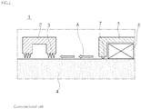
FIG. 1 , a bearing 6 contacts an end of ashaft 4 to enable smooth rotation of the shaft, and such bearing 6 is fixed and supported by a bearingsupporter 5. - In order to increase a lifespan of the bearing that assists in rotation of the
shaft 4 and to normally operate the bearing, bearing oil needs to be supplied. However, when the oil added to the bearing is introduced to theshaft 4 through the bearing and flows along theshaft 4, a problem that the oil is introduced into an inside of a turbine 1 (reference numeral A) occurs. In order to prevent such situation, according to the related art, abrush seal 7 is installed on the bearingsupporter 5 to block the flow. Further, anoil deflector 2 is disposed and alabyrinth seal 3 is installed on theoil deflector 2 in case the oil passes through thebrush seal 7, thereby preventing the bearing oil from flowing toward a center direction of theturbine 1. - However, when operating, the rotor inevitably moves in an axial direction or in a circumferential direction, and in this case, the labyrinth seal 3 of the
oil deflector 2 and thebrush seal 7 of thebearing supporter 5 may not function properly. - In this case, the bearing oil passes through the
oil deflector 2 and reacts with high-temperature and high-pressure gas or steam, as a result, the bearing oil is carbonized. - (Patent Document 1) U.S. Patent No.
US 4350345 A - A object of the present invention is to provide a structure for a rotor of removing bearing oil that is capable of suppressing carbonization caused by a reaction with high-temperature operating fluid at an oil deflector by removing bearing oil flowing along a shaft of the rotor between a bearing and the oil deflector by implementing a predetermined shape on the shaft of the rotor.
- In accordance with one aspect of the present invention, there is provided a structure for a rotor of removing bearing oil, including: a rotor shaft connecting a compressor section and a turbine section and disposed in a casing of a turbine; and an annular oil scattering means formed between an oil deflector and a bearing supporter on the rotor shaft in a circumferential direction to scatter bearing oil flowing from the bearing supporter toward the oil deflector along a surface of the rotor shaft.
- A direction in which the bearing oil is scattered by the oil scattering means may be directed between the bearing supporter and the casing.
- The oil scattering means may be provided as a scattering groove formed on the rotor shaft, and the scattering groove may be inclined toward the bearing supporter.
- A surface of the scattering groove that is adjacent to the bearing supporter may be inclined in multiple steps.
- The scattering groove may be formed in plural on the rotor shaft.
- The structure may further include a first interruption part disposed between the plurality of scattering grooves to interrupt flow of bearing oil from the bearing supporter toward the oil deflector.
- The first interruption part may be provided as a first fine groove formed between the plurality of scattering grooves.
- The first interruption part may be provided as a first fine protrusion formed between the plurality of scattering grooves.
- In accordance with another aspect of the present invention, there is provided a structure for a rotor of removing bearing oil, including: a rotor shaft disposed in a casing of a turbine; an annular oil blocking means formed between an oil deflector and a bearing supporter on the rotor shaft in a circumferential direction to block flow of bearing oil from the bearing supporter toward the oil deflector; and an annular oil scattering means formed on the oil blocking means in the circumferential direction to scatter the bearing oil flowing along the oil blocking means.
- A surface of the oil blocking means that is adjacent to the bearing supporter may be inclined, and a surface of the oil blocking means that is adjacent to the oil deflector may be stepped in order to block the flow of the bearing oil from the bearing supporter toward the oil deflector.
- A surface of the oil blocking means that is adjacent to the bearing supporter, and a surface of the oil blocking means that is adjacent to the oil deflector may be inclined toward the bearing supporter in order to block the flow of the bearing oil from the bearing supporter toward the oil deflector.
- A direction in which the bearing oil is scattered by the oil scattering means may be directed between the bearing supporter and the casing.
- The oil scattering means may be provided as a scattering groove formed in the oil blocking means on the rotor shaft, and the scattering groove may be inclined toward the bearing supporter.
- The scattering groove may be formed in plural on the rotor shaft.
- The structure may further include a second interruption part disposed between the oil blocking means and the bearing supporter on the rotor shaft to interrupt the flow of the bearing oil from the bearing supporter toward the oil deflector.
- The second interruption part may be provided as a second fine groove formed between the oil blocking means and the bearing supporter.
- The second interruption part may be provided as a second fine protrusion formed between the oil blocking means and the bearing supporter.
- The above and other objects, features and other advantages of the present invention will be more clearly understood from the following detailed description taken in conjunction with the accompanying drawings, in which:
-
FIG. 1 is a view illustrating a state in which bearing oil flows along a rotor shaft of a turbine according to the related art. -
FIG. 2 is a view illustrating a structure for a rotor according to a first embodiment of the present invention. -
FIG. 3 is a view illustrating a structure for a rotor according to a second embodiment of the present invention. -
FIG. 4 is a view illustrating a structure for a rotor according to a third embodiment of the present invention. -
FIG. 5 is a view illustrating a structure for a rotor according to a fourth embodiment of the present invention. -
FIG. 6 is a view illustrating a structure for a rotor according to a fifth embodiment of the present invention. -
FIG. 7 is a view illustrating a structure for a rotor according to a sixth embodiment of the present invention. -
FIG. 8 is a view illustrating a structure for a rotor according to a seventh embodiment of the present invention. -
FIG. 9 is a view illustrating a structure for a rotor according to an eighth embodiment of the present invention. -
FIG. 10 is a view illustrating a structure for a rotor according to a ninth embodiment of the present invention. -
FIG. 11 is a view illustrating a structure for a rotor according to a tenth embodiment of the present invention. -
FIG. 12 is a view illustrating a structure for a rotor according to an eleventh embodiment of the present invention. -
FIG. 13 is a view illustrating a structure for a rotor according to a twelfth embodiment of the present invention. - Hereinafter, a structure for a rotor of removing bearing oil according to preferred embodiments of the present invention will be described in detail with reference to the accompanying drawings.
-
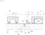
FIG. 2 is a view illustrating a structure for a rotor according to a first embodiment of the present invention. Referring toFIG. 2 , according to the first embodiment of the present invention, a structure for a rotor may include arotor shaft 30 and an oil scattering means 50. - First, the
rotor shaft 30 is provided as a part for connecting a compressor section and a turbine section that are components of a turbine, and may be disposed in acasing 12 of the turbine. Both sides of therotor shaft 30 may each be supported by abearing supporter 40 and installed so that therotor shaft 30 may smoothly rotate, and anoil deflector 20 may be disposed adjacent to therespective bearing supporter 40. Theoil deflector 20 prevents bearing oil that is added for smooth operation of the bearing from flowing along therotor shaft 30 to the compressor section or the turbine section. - Next, the oil scattering means 50 may be formed between the
oil deflector 20 and thebearing supporter 40 on therotor shaft 30 in a circumferential direction, to scatter the bearing oil flowing from thebearing supporter 40 toward theoil deflector 20 along a surface of therotor shaft 30.FIG. 2 illustrates a side cross-sectional view of therotor shaft 30, in which it is possible to confirm a form in which the oil scattering means 50 is formed on therotor shaft 30. - A direction in which the bearing oil is scattered by the oil scattering means 50 may be directed between the bearing
supporter 40 and thecasing 12. To this end, according to the first embodiment of the present invention, the oil scattering means 50 may be provided as a scatteringgroove 51 formed on therotor shaft 30. In addition, the scatteringgroove 51 may be formed to be inclined toward the bearingsupporter 40. - Referring to
FIG. 2 again, the scatteringgroove 51 may be configured of an one-side slope 51a and an opposite-side slope 51b that are inclined at a gradient Φ0, and agroove end 51 c. The gradient Φ0 may be appropriately selected according to an operation environment of the turbine. For example, when intending to scatter the bearing oil in a direction toward between the bearingsupporter 40 and thecasing 12, the slopes may be implemented to have an angle value toward an upper portion of the bearingsupporter 40 and a gradient of less than 90°. - The bearing oil added for smooth operation of a
bearing 41 may pass through abrush seal 42 installed on the bearingsupporter 40 and reach the scatteringgroove 51 along the rotor shaft 30 (reference numeral B). The bearing oil flowing along the one-side slop 51a of the scatteringgroove 51 is applied with centrifugal force due to the rotation of therotor shaft 30. The centrifugal force that is acted in a radial direction acts as a force to scatter the bearing oil toward an outer side of therotor shaft 30. As such, the flow of the bearing oil is blocked by the scatteringgroove 51, and the bearing oil may not flow toward theoil deflector 20. - Even though the bearing oil continuously flows along the one-
side slope 51 a, since the flow direction is bent at thegroove end 51 c, the flow of the bearing oil is disrupted again. Further, when flowing along the opposite-side slope 51b, the bearing oil is applied with the centrifugal force again to be scattered toward thecasing 12 and the bearing supporter 40 (reference numeral H). - That is, it is possible to effectively block the flow of the bearing oil toward the
oil deflector 20 from the bearingsupporter 40 merely by forming onescattering groove 51 on therotor shaft 30. - Next,
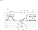
FIG. 3 is a view illustrating a structure for a rotor according to a second embodiment of the present invention. Referring toFIG. 3 , according to the second embodiment of the present invention, a structure for a rotor may include arotor shaft 30 and an oil scattering means 50. A description for therotor shaft 30 is the same as in the first embodiment of the present invention, and thus will be omitted. - Next, the oil scattering means 50 may be formed between the
oil deflector 20 and the bearingsupporter 40 on therotor shaft 30 in a circumferential direction, to scatter the bearing oil flowing from the bearingsupporter 40 toward theoil deflector 20 along the surface of therotor shaft 30.FIG. 3 illustrates a side cross-sectional view of therotor shaft 30, in which it is possible to confirm a form in which the oil scattering means 50 is formed on therotor shaft 30. - A direction in which the bearing oil is scattered by the oil scattering means 50 may be directed between the bearing
supporter 40 and thecasing 12. To this end, according to the second embodiment of the present invention, the oil scattering means 50 may be provided as scatteringgrooves rotor shaft 30. In addition, the scatteringgrooves supporter 40. - However, unlike the first embodiment of the present invention, according to the second embodiment of the present invention, the scattering
groove - That is, when the bearing oil added for smooth operation of the bearing 41 passes through the
brush seal 42 installed on the bearingsupporter 40 and reaches the scatteringgrooves rotor shaft 30, the flow of the bearing oil is primarily disrupted by the scatteringgroove 51 that is most adjacently disposed to the bearingsupporter 40. Further, if the bearing oil passes over thefirst scattering groove 51 and keeps flowing by movement of therotor shaft 30 in an axial direction or the circumferential direction during an operation process of the turbine, the flow of the bearing oil is disrupted again by thesecond scattering groove 52 disposed at the center. Here, thethird scattering groove 53 may be preliminarily formed in order to finally block the bearing oil passing over thesecond scattering groove 52. - Comparison of quantitative representation of an amount of the bearing oil removed by the
respective scattering grooves first scattering groove 51 is largest, and the amount of removed bearing oil will become smaller at thesecond scattering groove 52 and thethird scattering groove 53 in sequence due to sequential blocking of the flow. - That is, it is possible to block the flow of the bearing oil toward the
oil deflector 20 from the bearingsupporter 40 stage by stage by forming the plurality of scatteringgrooves rotor shaft 30. - Next,
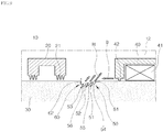
FIG. 4 is a view illustrating a structure for a rotor according to a third embodiment of the present invention. Referring toFIG. 4 , according to the third embodiment of the present invention, a structure for a rotor may include arotor shaft 30 and an oil scattering means 50. A description for therotor shaft 30 is the same as in the first embodiment of the present invention, and thus will be omitted. - The oil scattering means 50 may be formed between the
oil deflector 20 and the bearingsupporter 40 on therotor shaft 30 in a circumferential direction, to scatter the bearing oil flowing from the bearingsupporter 40 toward theoil deflector 20 along the surface of therotor shaft 30.FIG. 4 illustrates a side cross-sectional view of therotor shaft 30, in which it is possible to confirm a form in which the oil scattering means 50 is formed on therotor shaft 30. - A direction in which the bearing oil is scattered by the oil scattering means 50 may be directed between the bearing
supporter 40 and thecasing 12. To this end, according to the third embodiment of the present invention, the oil scattering means 50 may be provided as a scatteringgroove 51 formed on therotor shaft 30. In addition, the scatteringgroove 51 may be formed to be inclined toward the bearingsupporter 40. - Further, according to the third embodiment, unlike the first embodiment of the present invention, in the scattering
groove 51, amulti-step groove 54 inclined in multiple steps may be formed on the one-side slope 51a adjacent to the bearingsupporter 40. - Referring to
FIG. 4 again, the scatteringgroove 51 may be configured of an one-side slope 51a and an opposite-side slope 51b that are inclined at a gradient Φ1, and agroove end 51c. Further, themulti-step groove 54 may be configured of amulti-step slope 54a that is inclined at a gradient Φ2 and amulti-step groove end 54b. - The gradients Φ1 and Φ2 may be appropriately selected according to an operation environment of the turbine. For example, when intending to scatter the bearing oil in a direction toward between the bearing
supporter 40 and thecasing 12, the slopes may be implemented to have an angle value toward an upper portion of the bearingsupporter 40 and a gradient of less than 90° in relation to a vertical line. - Further, the gradients Φ1 and Φ2 may not only be identical to each other but may also be different from each other. For example, the gradient Φ2 may be relatively larger than the gradient Φ1 in relation to the vertical line, such that the scattering force by the centrifugal force may be adjusted.
- That is, it is possible to adjust a degree of scattering of the bearing oil flowing toward the
oil deflector 20 from the bearingsupporter 40 through the same gradient or different gradients, by forming themulti-step groove 54 in addition to the scatteringgroove 51 on therotor shaft 30. - Next,
FIG. 5 is a view illustrating a structure for a rotor according to a fourth embodiment of the present invention. Referring toFIG. 5 , according to the fourth embodiment of the present invention, a structure for a rotor may include arotor shaft 30 and an oil scattering means 50. A description for therotor shaft 30 is the same as in the first embodiment of the present invention, and thus will be omitted. - The oil scattering means 50 may be formed between the
oil deflector 20 and the bearingsupporter 40 on therotor shaft 30 in a circumferential direction, to scatter the bearing oil flowing from the bearingsupporter 40 toward theoil deflector 20 along the surface of therotor shaft 30.FIG. 5 illustrates a side cross-sectional view of therotor shaft 30, in which it is possible to confirm a form in which the oil scattering means 50 is formed on therotor shaft 30. - A direction in which the bearing oil is scattered by the oil scattering means 50 may be directed between the bearing
supporter 40 and thecasing 12. To this end, according to the fourth embodiment of the present invention, the oil scattering means 50 may be provided as scatteringgrooves multi-step grooves rotor shaft 30. In addition, the scatteringgrooves multi-step grooves supporter 40. - However, unlike the first embodiment of the present invention, according to the fourth embodiment of the present invention, the scattering
groove multi-step groove - That is, when the bearing oil added for smooth operation of a bearing 41 passes through a
brush seal 42 installed on the bearingsupporter 40 and reaches the scatteringgrooves multi-step grooves rotor shaft 30, the flow of the bearing oil is primarily disrupted by the scatteringgroove 51 and themulti-step groove 54 that are most adjacently disposed to the bearingsupporter 40. Further, if the bearing oil passes over thefirst scattering groove 51 and the firstmulti-step groove 54 and keeps flowing by the movement of therotor shaft 30 in the axial direction or the circumferential direction during the operation process of the turbine, the flow of the bearing oil is disrupted again by thesecond scattering groove 52 and the secondmulti-step groove 55 that are disposed at the center. Here, thethird scattering groove 53 and the thirdmulti-step groove 56 may be preliminarily formed in order to finally block the bearing oil passing over thesecond scattering groove 52 and the secondmulti-step groove 55. - Comparison of quantitative representation of an amount of the bearing oil removed by the
respective scattering grooves multi-step grooves first scattering groove 51 and the firstmulti-step groove 54 is largest, and the amount of removed bearing oil will become smaller at thesecond scattering groove 52 and the secondmulti-step groove 55, and thethird scattering groove 53 and the thirdmulti-step groove 56 in sequence due to sequential blocking of the flow. - That is, it is possible to block the flow of the bearing oil toward the
oil deflector 20 from the bearingsupporter 40 stage by stage by forming the plurality of scatteringgrooves multi-step grooves rotor shaft 30. The gradients Φ1 and Φ2 of the scatteringgrooves multi-step grooves - Next,
FIG. 6 is a view illustrating a structure for a rotor according to a fifth embodiment of the present invention. Referring toFIG. 6 , according to the fifth embodiment of the present invention, a structure for a rotor may include arotor shaft 30, an oil scattering means 50, and a first interruption part. A description for therotor shaft 30 is the same as in the first embodiment of the present invention, and thus will be omitted. - The oil scattering means 50 may be formed between the
oil deflector 20 and the bearingsupporter 40 on therotor shaft 30 in a circumferential direction, to scatter the bearing oil flowing from the bearingsupporter 40 toward theoil deflector 20 along the surface of therotor shaft 30.FIG. 6 illustrates a side cross-sectional view of therotor shaft 30, in which it is possible to confirm a form in which the oil scattering means 50 is formed on therotor shaft 30. - A direction in which the bearing oil is scattered by the oil scattering means 50 may be directed between the bearing
supporter 40 and thecasing 12. To this end, according to the fifth embodiment of the present invention, the oil scattering means 50 may be provided as scatteringgrooves rotor shaft 30. In addition, the scatteringgrooves supporter 40. - Here, the scattering
grooves - Further, the first interruption part may be disposed between the plurality of scattering
grooves oil deflector 20 from the bearingsupporter 40. - According to the fifth embodiment of the present invention, the first interruption part may be formed as a first
fine groove 57 that is formed between the plurality of scatteringgrooves FIG. 6 , two firstfine grooves 57 are formed between three scatteringgrooves respective scattering grooves rotor shaft 30 even in this case, thus the bearing oil is also scattered at the firstfine groove 57. - Accordingly, it is possible to block the flow of the bearing oil toward the
oil deflector 20 from the bearingsupporter 40 more gradationally. -
FIG. 7 is a view illustrating a structure for a rotor according to a sixth embodiment of the present invention. Referring toFIG. 7 , according to the sixth embodiment of the present invention, a structure for a rotor may include arotor shaft 30, an oil scattering means 50, and a first interruption part. A description for therotor shaft 30 and the oil scattering means 50 is the same as in the fifth embodiment of the present invention, and thus will be omitted. - The first interruption part may be disposed between the plurality of scattering
grooves oil deflector 20 from the bearingsupporter 40. - According to the sixth embodiment of the present invention, the first interruption part may be formed as a first
fine protrusion 58 that is formed between the plurality of scatteringgrooves FIG. 7 , two firstfine protrusions 58 are formed between three scatteringgrooves respective scattering grooves rotor shaft 30 even in this case, thus the bearing oil is also scattered at the firstfine protrusion 58. That is, the bearing oil is scattered toward the outer side of therotor shaft 30 along a protrusion surface of the firstfine protrusion 58. Accordingly, it is possible to block the flow of the bearing oil toward theoil deflector 20 from the bearingsupporter 40 more gradationally. - Next,
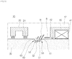
FIG. 8 is a view illustrating a structure for a rotor according to a seventh embodiment of the present invention. Referring toFIG. 8 , according to the seventh embodiment of the present invention, a structure for a rotor may include arotor shaft 30, an oil scattering means 50, and an oil blocking means 60. - First, the
rotor shaft 30 is provided as a part for connecting the compressor section and the turbine section that are components of the turbine, and may be disposed in thecasing 12 of the turbine. Both sides of therotor shaft 30 may each be supported by the bearingsupporter 40 and installed so that therotor shaft 30 may smoothly rotate, and theoil deflector 20 may be disposed adjacent to therespective bearing supporter 40. Theoil deflector 20 prevents bearing oil that is added for smooth operation of the bearing from flowing along therotor shaft 30 to the compressor section or the turbine section. - Next, the oil blocking means 60 may be formed between the
oil deflector 20 and the bearingsupporter 40 on therotor shaft 30 in a circumferential direction, to block the flow of the bearing oil from the bearingsupporter 40 toward theoil deflector 20. - According to the seventh embodiment of the present invention, a surface of the oil blocking means 60 that is adjacent to the bearing
supporter 40 may be inclined, and a surface of the oil blocking means 60 that is adjacent to theoil deflector 20 may be stepped in order to block the flow of the bearing oil from the bearingsupporter 40 toward theoil deflector 20. That is, the oil blocking means 60 may be configured of an inclinedflow inducing surface 61 and astep part 62. The bearing oil flows along the inclinedflow inducing surface 61 and then the flow of the bearing oil is blocked at thestep part 62 formed in an almost vertical direction. - Further, the oil scattering means 50 may be formed on the oil blocking means 60 in a circumferential direction, to scatter the bearing oil flowing from the bearing
supporter 40 toward theoil deflector 20 along the surface of therotor shaft 30. -
FIG. 8 illustrates a side cross-sectional view of therotor shaft 30, in which it is possible to confirm a form in which the oil blocking means 60 and the oil scattering means 50 are formed on therotor shaft 30. - A direction in which the bearing oil is scattered by the oil scattering means 50 may be directed between the bearing
supporter 40 and thecasing 12. To this end, according to the seventh embodiment of the present invention, the oil scattering means 50 may be provided as a plurality of scatteringgrooves rotor shaft 30. In addition, the scatteringgrooves supporter 40. - According to the seventh embodiment of the present invention, the oil blocking means 60 is formed on the
rotor shaft 30, and the plurality of scatteringgrooves -
FIG. 9 is a view illustrating a structure for a rotor according to an eighth embodiment of the present invention. Referring toFIG. 9 , according to the eight embodiment of the present invention, a structure for a rotor may include arotor shaft 30, an oil scattering means 50, and an oil blocking means 60. A description for therotor shaft 30 is the same as in the seventh embodiment of the present invention, and thus will be omitted. - The oil blocking means 60 may be formed between the
oil deflector 20 and the bearingsupporter 40 on therotor shaft 30 in a circumferential direction, to block the flow of the bearing oil from the bearingsupporter 40 toward theoil deflector 20. - According to the eight embodiment of the present invention, a surface of the oil blocking means 60 that is adjacent to the bearing
supporter 40 may be inclined, and a surface of the oil blocking means 60 that is adjacent to theoil deflector 20 may be stepped in order to block the flow of the bearing oil from the bearingsupporter 40 toward theoil deflector 20. That is, the oil blocking means 60 may be configured of the inclinedflow inducing surface 61 and thestep part 62. The bearing oil flows along the inclinedflow inducing surface 61 and then the flow of the bearing oil is blocked at thestep part 62 formed in an almost vertical direction. - Further, the oil scattering means 50 may be formed on the oil blocking means 60 in a circumferential direction, to scatter the bearing oil flowing from the bearing
supporter 40 toward theoil deflector 20 along the surface of therotor shaft 30. -
FIG. 9 illustrates a side cross-sectional view of therotor shaft 30, in which it is possible to confirm a form in which the oil blocking means 60 and the oil scattering means 50 are formed on therotor shaft 30. - A direction in which the bearing oil is scattered by the oil scattering means 50 may be directed between the bearing
supporter 40 and thecasing 12. To this end, according to the eight embodiment of the present invention, the oil scattering means 50 may be provided as a plurality of scatteringgrooves multi-step grooves rotor shaft 30. In addition, the scatteringgrooves multi-step grooves supporter 40. - In this case, the flow of the bearing oil may be blocked stage by stage. The number of scattering grooves and multi-step grooves may be various according to the operation environment, but in the eighth embodiment of the present invention, the number of scattering grooves and the number of multi-step grooves are three, respectively.
- That is, when the bearing oil added for smooth operation of the bearing 41 passes through the
brush seal 42 installed on the bearingsupporter 40 and reaches the scatteringgrooves multi-step grooves rotor shaft 30, the flow of the bearing oil is primarily disrupted by the scatteringgroove 51 and themulti-step groove 54 that are most adjacently disposed to the bearingsupporter 40. Further, if the bearing oil passes over thefirst scattering groove 51 and the firstmulti-step groove 54 and keeps flowing by the movement of therotor shaft 30 in the axial direction or the circumferential direction during the operation process of the turbine, the flow of the bearing oil is disrupted again by thesecond scattering groove 52 and the secondmulti-step groove 55 that are disposed at the center. Here, thethird scattering groove 53 and the thirdmulti-step groove 56 may be preliminarily formed in order to finally block the bearing oil passing over thesecond scattering groove 52 and the secondmulti-step groove 55. - Comparison of quantitative representation of an amount of the bearing oil removed by the
respective scattering grooves multi-step grooves first scattering groove 51 and the firstmulti-step groove 54 is largest, and the amount of removed bearing oil will become smaller at thesecond scattering groove 52 and the secondmulti-step groove 55, and thethird scattering groove 53 and the thirdmulti-step groove 56 in sequence due to sequential blocking of the flow. - That is, it is possible to block the flow of the bearing oil toward the
oil deflector 20 from the bearingsupporter 40 stage by stage by the oil blocking means 60 and by forming the plurality of scatteringgrooves multi-step grooves rotor shaft 30. -
FIG. 10 is a view illustrating a structure for a rotor according to a ninth embodiment of the present invention. Referring toFIG. 10 , according to the ninth embodiment of the present invention, a structure for a rotor may include arotor shaft 30, an oil scattering means 50, and an oil blocking means 60. A description for therotor shaft 30 is the same as in the seventh embodiment of the present invention, and thus will be omitted. - The oil blocking means 60 may be formed between the
oil deflector 20 and the bearingsupporter 40 on therotor shaft 30 in a circumferential direction, to block the flow of the bearing oil from the bearingsupporter 40 toward theoil deflector 20. - According to the ninth embodiment of the present invention, a surface of the oil blocking means 60 that is adjacent to the bearing
supporter 40, and a surface of the oil blocking means 60 that is adjacent to theoil deflector 20 may be inclined toward the bearingsupporter 40 in order to block the flow of the bearing oil from the bearingsupporter 40 toward theoil deflector 20. That is, the oil blocking means 60 may be configured of the inclinedflow inducing surface 61 and an inclined blockingpart 63. The bearing oil flows along the inclinedflow inducing surface 61 and then the flow of the bearing oil is blocked again at the inclined blockingpart 63 that is inclined in the same direction. - Further, the oil scattering means 50 may be formed on the oil blocking means 60 in a circumferential direction, to scatter the bearing oil flowing from the bearing
supporter 40 toward theoil deflector 20 along the surface of therotor shaft 30. -
FIG. 10 illustrates a side cross-sectional view of therotor shaft 30, in which it is possible to confirm a form in which the oil blocking means 60 and the oil scattering means 50 are formed on therotor shaft 30. - A direction in which the bearing oil is scattered by the oil scattering means 50 may be directed between the bearing
supporter 40 and thecasing 12. To this end, according to the ninth embodiment of the present invention, the oil scattering means 50 may be provided as a plurality of scatteringgrooves rotor shaft 30. In addition, the scatteringgrooves supporter 40. - According to the ninth embodiment of the present invention, the oil blocking means 60 is formed on the
rotor shaft 30, and the plurality of scatteringgrooves -
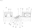
FIG. 11 is a view illustrating a structure for a rotor according to a tenth embodiment of the present invention. According to the tenth embodiment of the present invention, a structure for a rotor may include arotor shaft 30, an oil scattering means 50, and an oil blocking means 60. A description for therotor shaft 30 is the same as in the seventh embodiment of the present invention, and thus will be omitted. - The oil blocking means 60 may be formed between the
oil deflector 20 and the bearingsupporter 40 on therotor shaft 30 in a circumferential direction, to block the flow of the bearing oil from the bearingsupporter 40 toward theoil deflector 20. - According to the tenth embodiment of the present invention, a surface of the oil blocking means 60 that is adjacent to the bearing
supporter 40, and a surface of the oil blocking means 60 that is adjacent to theoil deflector 20 may be inclined toward the bearingsupporter 40 in order to block the flow of the bearing oil from the bearingsupporter 40 toward theoil deflector 20. That is, the oil blocking means 60 may be configured of the inclinedflow inducing surface 61 and the inclined blockingpart 63. The bearing oil flows along the inclinedflow inducing surface 61 and then the flow of the bearing oil is blocked at the inclined blockingpart 63 that is inclined in the same direction. - Further, the oil scattering means 50 may be formed on the oil blocking means 60 in a circumferential direction, to scatter the bearing oil flowing from the bearing
supporter 40 toward theoil deflector 20 along the surface of therotor shaft 30. -
FIG. 11 illustrates a side cross-sectional view of therotor shaft 30, in which it is possible to confirm a form in which the oil blocking means 60 and the oil scattering means 50 are formed on therotor shaft 30. - A direction in which the bearing oil is scattered by the oil scattering means 50 may be directed between the bearing
supporter 40 and thecasing 12. To this end, according to the tenth embodiment of the present invention, the oil scattering means 50 may be provided as a plurality of scatteringgrooves multi-step grooves rotor shaft 30. In addition, the scatteringgrooves multi-step grooves supporter 40. - In this case, the flow of the bearing oil may be blocked stage by stage. The number of scattering grooves and multi-step grooves may be various according to the operation environment, but in the tenth embodiment of the present invention, the number of scattering grooves and the number of multi-step grooves are three, respectively.
- That is, when the bearing oil added for smooth operation of the bearing 41 passes through the
brush seal 42 installed on the bearingsupporter 40 and reaches the scatteringgrooves multi-step grooves rotor shaft 30, the flow of the bearing oil is primarily disrupted by the scatteringgroove 51 and themulti-step groove 54 that are most adjacently disposed to the bearingsupporter 40. Further, if the bearing oil passes over thefirst scattering groove 51 and the firstmulti-step groove 54 and keeps flowing by the movement of therotor shaft 30 in the axial direction or the circumferential direction during the operation process of the turbine, the flow of the bearing oil is disrupted again by thesecond scattering groove 52 and the secondmulti-step groove 55 that are disposed at the center. Here, thethird scattering groove 53 and the thirdmulti-step groove 56 may be preliminarily formed in order to finally block the bearing oil passing over thesecond scattering groove 52 and the secondmulti-step groove 55. - Comparison of quantitative representation of an amount of the bearing oil removed by the
respective scattering grooves multi-step grooves first scattering groove 51 and the firstmulti-step groove 54 is largest, and the amount of removed bearing oil will become smaller at thesecond scattering groove 52 and the secondmulti-step groove 55, and thethird scattering groove 53 and the thirdmulti-step groove 56 in sequence due to sequential blocking of the flow. - That is, it is possible to block the flow of the bearing oil toward the
oil deflector 20 from the bearingsupporter 40 stage by stage by the oil blocking means 60 and by forming the plurality of scatteringgrooves multi-step grooves rotor shaft 30. -
FIG. 12 is a view illustrating a structure for a rotor according to an eleventh embodiment of the present invention. According to the eleventh embodiment of the present invention, a structure for a rotor may include arotor shaft 30, an oil scattering means 50, an oil blocking means 60, and a second interruption part. A description for therotor shaft 30, the oil scattering means 50, and the oil blocking means 60 is the same as in the ninth embodiment of the present invention, and thus will be omitted. - The second interruption part may be formed between the oil blocking means 60 and the bearing
supporter 40 on therotor shaft 30, to block the flow of the bearing oil from the bearingsupporter 40 toward theoil deflector 20. - According to the eleventh embodiment of the present invention, the second interruption part may be provided as a second
fine groove 64 that is formed between the oil blocking means 60 and the bearingsupporter 40. In this case, the flow of the bearing oil is interrupted by the secondfine groove 64 in advance before the bearing oil is introduced into the oil blocking means 60 and the oil scattering means 50, and the bearing oil may be scattered toward the outer side of therotor shaft 30 by the centrifugal force. - As such, according to the eleventh embodiment of the present invention, the flow of the bearing oil may be blocked and the bearing oil may be scattered stage by stage, thereby making it possible to more suppress the flow toward the
oil deflector 20. -
FIG. 13 is a view illustrating a structure for a rotor according to a twelfth embodiment of the present invention. According to the twelfth embodiment of the present invention, a structure for a rotor may include arotor shaft 30, an oil scattering means 50, an oil blocking means 60, and a second interruption part. A description for therotor shaft 30, the oil scattering means 50, and the oil blocking means 60 is the same as in the ninth embodiment of the present invention, and thus will be omitted. - The second interruption part may be formed between the oil blocking means 60 and the bearing
supporter 40 on therotor shaft 30, to block the flow of the bearing oil from the bearingsupporter 40 toward theoil deflector 20. - According to the twelfth embodiment of the present invention, the second interruption part may be provided as a second
fine protrusion 65 that is formed between the oil blocking means 60 and the bearingsupporter 40. In this case, the flow of the bearing oil is interrupted by the secondfine protrusion 65 in advance before the bearing oil is introduced into the oil blocking means 60 and the oil scattering means 50, and the bearing oil may be scattered toward the outer side of therotor shaft 30 by the centrifugal force. - As such, according to the twelfth embodiment of the present invention, the flow of the bearing oil may be blocked and the bearing oil may be scattered stage by stage, thereby making it possible to more suppress the flow toward the
oil deflector 20. - According to the embodiments of the present invention, it is possible to block the flow of the bearing oil from the bearing toward the oil deflector direction by forming a groove having a predetermined shape on the shaft positioned between the bearing of the rotor and the oil deflector.
- Further, it is possible to remove the bearing oil by allowing the formed groove to have a slope toward the bearing direction so that the bearing oil introduced into the formed groove does not remain but is scattered in the bearing direction at the time of rotation of the shaft.
- Further, it is possible to more effectively block the flow of the bearing oil by disposing a plurality of grooves formed as described above on the shaft of the rotor, or by configuring a multi-step groove.
- Further, it is possible to reinforce blocking and scattering of the bearing oil by implementing the fine protrusion or the fine depression adjacent to the formed groove.
- This ultimately may prevent the carbonization caused by the reaction with the high-temperature operating fluid at the oil deflector by blocking the flow of the bearing oil toward the oil deflector direction from the bearing.
- The above description merely illustrates specific embodiments of the structure for a rotor of removing bearing oil.
- Therefore, it is to be noted that the present invention may be variously substituted and modified by those skilled in the art without departing from the spirit of the present invention as disclosed in the accompanying claims.
Claims (15)
- A structure for a rotor of removing bearing oil, comprising:a rotor shaft disposed in a casing of a turbine; andan annular oil scattering means formed between an oil deflector and a bearing supporter on the rotor shaft in a circumferential direction to scatter bearing oil flowing from the bearing supporter toward the oil deflector along a surface of the rotor shaft.
- The structure of claim 1, wherein the oil scattering means is provided as a scattering groove formed on the rotor shaft, and the scattering groove is inclined toward the bearing supporter.
- The structure of claim 2, wherein a surface of the scattering groove that is adjacent to the bearing supporter is inclined in multiple steps.
- The structure of claim 2 or 3, wherein the scattering groove is formed in plural on the rotor shaft.
- The structure of claim 4, further comprising:a first interruption part disposed between the plurality of scattering grooves to interrupt flow of the bearing oil from the bearing supporter toward the oil deflector.
- The structure of claim 5, wherein the first interruption part is provided as a first fine groove formed between the plurality of scattering grooves.
- The structure of claim 5, wherein the first interruption part is provided as a first fine protrusion formed between the plurality of scattering grooves.
- The structure of claim 1, further comprising:an annular oil blocking means formed between the oil deflector and the bearing supporter on the rotor shaft in the circumferential direction to block flow of the bearing oil from the bearing supporter toward the oil deflector,wherein the oil scattering means is formed on the oil blocking means in the circumferential direction.
- The structure of claim 8, wherein a surface of the oil blocking means that is adjacent to the bearing supporter is inclined, and a surface of the oil blocking means that is adjacent to the oil deflector is stepped in order to block the flow of the bearing oil from the bearing supporter toward the oil deflector.
- The structure of claim 8, wherein a surface of the oil blocking means that is adjacent to the bearing supporter, and a surface of the oil blocking means that is adjacent to the oil deflector are inclined toward the bearing supporter in order to block the flow of the bearing oil from the bearing supporter toward the oil deflector.
- The structure of claim 9 or 10, wherein the oil scattering means is provided as a scattering groove formed in the oil blocking means on the rotor shaft, and the scattering groove is inclined toward the bearing supporter.
- The structure of claim 11, wherein the scattering groove is formed in plural on the rotor shaft.
- The structure of claim 9 or 10, further comprising:a second interruption part disposed between the oil blocking means and the bearing supporter on the rotor shaft to interrupt the flow of the bearing oil from the bearing supporter toward the oil deflector.
- The structure of claim 13, wherein the second interruption part is provided as a second fine groove formed between the oil blocking means and the bearing supporter.
- The structure of claim 13, wherein the second interruption part is provided as a second fine protrusion formed between the oil blocking means and the bearing supporter.
Applications Claiming Priority (1)
| Application Number | Priority Date | Filing Date | Title |
|---|---|---|---|
| KR1020150178518 | 2015-12-14 |
Publications (3)
| Publication Number | Publication Date |
|---|---|
| EP3225791A2 true EP3225791A2 (en) | 2017-10-04 |
| EP3225791A3 EP3225791A3 (en) | 2017-11-15 |
| EP3225791B1 EP3225791B1 (en) | 2020-02-05 |
Family
ID=57482333
Family Applications (1)
| Application Number | Title | Priority Date | Filing Date |
|---|---|---|---|
| EP16202247.9A Active EP3225791B1 (en) | 2015-12-14 | 2016-12-05 | Structure for rotor of removing bearing oil |
Country Status (3)
| Country | Link |
|---|---|
| US (1) | US20170167294A1 (en) |
| EP (1) | EP3225791B1 (en) |
| JP (1) | JP6380767B2 (en) |
Citations (1)
| Publication number | Priority date | Publication date | Assignee | Title |
|---|---|---|---|---|
| US4350345A (en) | 1981-04-01 | 1982-09-21 | General Electric Company | Air-sealed oil deflector |
Family Cites Families (12)
| Publication number | Priority date | Publication date | Assignee | Title |
|---|---|---|---|---|
| JPS5434853U (en) * | 1977-08-15 | 1979-03-07 | ||
| JPS57152406U (en) * | 1981-03-20 | 1982-09-24 | ||
| JPS61164402U (en) * | 1985-04-01 | 1986-10-13 | ||
| US5890881A (en) * | 1996-11-27 | 1999-04-06 | Alliedsignal Inc. | Pressure balanced turbocharger rotating seal |
| DE10011063A1 (en) * | 2000-03-07 | 2001-09-27 | Daimler Chrysler Ag | Labyrinth seal for shaft of electric motor is made up of two sections, outer section having annular components which form conical seal gaps with surface of other component |
| JP2003074491A (en) * | 2001-09-04 | 2003-03-12 | Nsk Ltd | Water pump seal device, water pump rotation support device, and water pump |
| US7056088B2 (en) * | 2004-04-21 | 2006-06-06 | General Electric Company | Steam turbine rotor temperature control at oil deflector |
| FR2878287B1 (en) * | 2004-11-25 | 2009-05-22 | Snecma Moteurs Sa | DUAL FLOW DOUBLE BODY TURBOREACTOR WITH REVERSE ELECTRIC CURRENT GENERATOR |
| GB0720479D0 (en) * | 2007-10-13 | 2007-11-28 | Cummins Turbo Tech Ltd | Rotating machine and oil control device |
| GB201200542D0 (en) * | 2012-01-13 | 2012-02-29 | Cummins Ltd | Turbomachine shaft sealing arrangement |
| WO2014138617A1 (en) * | 2013-03-08 | 2014-09-12 | United Technologies Corporation | Fluid-cooled seal arrangement for a gas turbine engine |
| US9683600B2 (en) * | 2013-09-16 | 2017-06-20 | Bret J. Park | Sleeve bearing for turbocharging device |
-
2016
- 2016-11-11 JP JP2016220564A patent/JP6380767B2/en active Active
- 2016-12-05 EP EP16202247.9A patent/EP3225791B1/en active Active
- 2016-12-12 US US15/376,064 patent/US20170167294A1/en not_active Abandoned
Patent Citations (1)
| Publication number | Priority date | Publication date | Assignee | Title |
|---|---|---|---|---|
| US4350345A (en) | 1981-04-01 | 1982-09-21 | General Electric Company | Air-sealed oil deflector |
Also Published As
| Publication number | Publication date |
|---|---|
| JP6380767B2 (en) | 2018-08-29 |
| JP2017110636A (en) | 2017-06-22 |
| US20170167294A1 (en) | 2017-06-15 |
| EP3225791B1 (en) | 2020-02-05 |
| EP3225791A3 (en) | 2017-11-15 |
Similar Documents
| Publication | Publication Date | Title |
|---|---|---|
| CA2625591C (en) | Blade retention system for use in a gas turbine engine | |
| EP2613000B1 (en) | System for axial retention of rotating segments of a turbine and corresponding method | |
| JP5802217B2 (en) | Abrasive seal with axial displacement | |
| EP2896791A1 (en) | Mistuned airfoil assemblies | |
| EP3159491B1 (en) | Turbine's sealing assembly | |
| US10876411B2 (en) | Non-axisymmetric end wall contouring with forward mid-passage peak | |
| EP2861831B1 (en) | Rotor assembly with interlocking tabs | |
| JP6557478B2 (en) | Turbine bucket and method for balancing turbine bucket tip shroud | |
| CN102817642B (en) | For the compliance plate seal assemblies of turbo machine | |
| US20140169954A1 (en) | Centrifugal impeller and turbomachine | |
| EP3190267A1 (en) | Structure for multi-stage sealing of turbine | |
| JP2010059968A (en) | Turbine airfoil clocking | |
| CN103422904A (en) | Turbomachine having clearance control capability and system therefor | |
| CN107075957A (en) | Turbine blisk and its manufacture method | |
| EP3048343A1 (en) | Multi-stage inter shaft ring seal | |
| EP3225791B1 (en) | Structure for rotor of removing bearing oil | |
| EP3222811A1 (en) | Damping vibrations in a gas turbine | |
| JP2011137454A (en) | Turbine engine rotor blade and rotor wheel | |
| EP2211025A2 (en) | Discrete Load Fins For Individual Stator Vanes | |
| CN102052097A (en) | Turbo machine efficiency equalizer system | |
| EP2997230B1 (en) | Tangential blade root neck conic | |
| EP2871332B1 (en) | Tapered thread for use in a gas turbine | |
| KR101753026B1 (en) | Structure for removing bearing oil and rotor shaft having the same and turbomachine | |
| EP1443179A2 (en) | A rotor and a retaining plate for the same | |
| RU2620622C2 (en) | Working wheel of turbomachinery and turbomachinery |
Legal Events
| Date | Code | Title | Description |
|---|---|---|---|
| PUAI | Public reference made under article 153(3) epc to a published international application that has entered the european phase |
Free format text: ORIGINAL CODE: 0009012 |
|
| STAA | Information on the status of an ep patent application or granted ep patent |
Free format text: STATUS: REQUEST FOR EXAMINATION WAS MADE |
|
| 17P | Request for examination filed |
Effective date: 20161205 |
|
| AK | Designated contracting states |
Kind code of ref document: A2 Designated state(s): AL AT BE BG CH CY CZ DE DK EE ES FI FR GB GR HR HU IE IS IT LI LT LU LV MC MK MT NL NO PL PT RO RS SE SI SK SM TR |
|
| AX | Request for extension of the european patent |
Extension state: BA ME |
|
| PUAL | Search report despatched |
Free format text: ORIGINAL CODE: 0009013 |
|
| AK | Designated contracting states |
Kind code of ref document: A3 Designated state(s): AL AT BE BG CH CY CZ DE DK EE ES FI FR GB GR HR HU IE IS IT LI LT LU LV MC MK MT NL NO PL PT RO RS SE SI SK SM TR |
|
| AX | Request for extension of the european patent |
Extension state: BA ME |
|
| RIC1 | Information provided on ipc code assigned before grant |
Ipc: F01D 25/16 20060101AFI20171010BHEP Ipc: F01D 25/18 20060101ALI20171010BHEP Ipc: F16J 15/16 20060101ALI20171010BHEP |
|
| RBV | Designated contracting states (corrected) |
Designated state(s): AL AT BE BG CH CY CZ DE DK EE ES FI FR GB GR HR HU IE IS IT LI LT LU LV MC MK MT NL NO PL PT RO RS SE SI SK SM TR |
|
| GRAP | Despatch of communication of intention to grant a patent |
Free format text: ORIGINAL CODE: EPIDOSNIGR1 |
|
| STAA | Information on the status of an ep patent application or granted ep patent |
Free format text: STATUS: GRANT OF PATENT IS INTENDED |
|
| INTG | Intention to grant announced |
Effective date: 20190705 |
|
| GRAS | Grant fee paid |
Free format text: ORIGINAL CODE: EPIDOSNIGR3 |
|
| GRAA | (expected) grant |
Free format text: ORIGINAL CODE: 0009210 |
|
| STAA | Information on the status of an ep patent application or granted ep patent |
Free format text: STATUS: THE PATENT HAS BEEN GRANTED |
|
| AK | Designated contracting states |
Kind code of ref document: B1 Designated state(s): AL AT BE BG CH CY CZ DE DK EE ES FI FR GB GR HR HU IE IS IT LI LT LU LV MC MK MT NL NO PL PT RO RS SE SI SK SM TR |
|
| REG | Reference to a national code |
Ref country code: GB Ref legal event code: FG4D |
|
| REG | Reference to a national code |
Ref country code: AT Ref legal event code: REF Ref document number: 1230047 Country of ref document: AT Kind code of ref document: T Effective date: 20200215 |
|
| REG | Reference to a national code |
Ref country code: DE Ref legal event code: R096 Ref document number: 602016029044 Country of ref document: DE |
|
| REG | Reference to a national code |
Ref country code: IE Ref legal event code: FG4D |
|
| REG | Reference to a national code |
Ref country code: CH Ref legal event code: EP |
|
| REG | Reference to a national code |
Ref country code: NL Ref legal event code: MP Effective date: 20200205 |
|
| PG25 | Lapsed in a contracting state [announced via postgrant information from national office to epo] |
Ref country code: RS Free format text: LAPSE BECAUSE OF FAILURE TO SUBMIT A TRANSLATION OF THE DESCRIPTION OR TO PAY THE FEE WITHIN THE PRESCRIBED TIME-LIMIT Effective date: 20200205 Ref country code: NO Free format text: LAPSE BECAUSE OF FAILURE TO SUBMIT A TRANSLATION OF THE DESCRIPTION OR TO PAY THE FEE WITHIN THE PRESCRIBED TIME-LIMIT Effective date: 20200505 Ref country code: PT Free format text: LAPSE BECAUSE OF FAILURE TO SUBMIT A TRANSLATION OF THE DESCRIPTION OR TO PAY THE FEE WITHIN THE PRESCRIBED TIME-LIMIT Effective date: 20200628 Ref country code: FI Free format text: LAPSE BECAUSE OF FAILURE TO SUBMIT A TRANSLATION OF THE DESCRIPTION OR TO PAY THE FEE WITHIN THE PRESCRIBED TIME-LIMIT Effective date: 20200205 |
|
| REG | Reference to a national code |
Ref country code: LT Ref legal event code: MG4D |
|
| PG25 | Lapsed in a contracting state [announced via postgrant information from national office to epo] |
Ref country code: BG Free format text: LAPSE BECAUSE OF FAILURE TO SUBMIT A TRANSLATION OF THE DESCRIPTION OR TO PAY THE FEE WITHIN THE PRESCRIBED TIME-LIMIT Effective date: 20200505 Ref country code: IS Free format text: LAPSE BECAUSE OF FAILURE TO SUBMIT A TRANSLATION OF THE DESCRIPTION OR TO PAY THE FEE WITHIN THE PRESCRIBED TIME-LIMIT Effective date: 20200605 Ref country code: SE Free format text: LAPSE BECAUSE OF FAILURE TO SUBMIT A TRANSLATION OF THE DESCRIPTION OR TO PAY THE FEE WITHIN THE PRESCRIBED TIME-LIMIT Effective date: 20200205 Ref country code: LV Free format text: LAPSE BECAUSE OF FAILURE TO SUBMIT A TRANSLATION OF THE DESCRIPTION OR TO PAY THE FEE WITHIN THE PRESCRIBED TIME-LIMIT Effective date: 20200205 Ref country code: HR Free format text: LAPSE BECAUSE OF FAILURE TO SUBMIT A TRANSLATION OF THE DESCRIPTION OR TO PAY THE FEE WITHIN THE PRESCRIBED TIME-LIMIT Effective date: 20200205 Ref country code: GR Free format text: LAPSE BECAUSE OF FAILURE TO SUBMIT A TRANSLATION OF THE DESCRIPTION OR TO PAY THE FEE WITHIN THE PRESCRIBED TIME-LIMIT Effective date: 20200506 |
|
| PG25 | Lapsed in a contracting state [announced via postgrant information from national office to epo] |
Ref country code: NL Free format text: LAPSE BECAUSE OF FAILURE TO SUBMIT A TRANSLATION OF THE DESCRIPTION OR TO PAY THE FEE WITHIN THE PRESCRIBED TIME-LIMIT Effective date: 20200205 |
|
| PG25 | Lapsed in a contracting state [announced via postgrant information from national office to epo] |
Ref country code: SK Free format text: LAPSE BECAUSE OF FAILURE TO SUBMIT A TRANSLATION OF THE DESCRIPTION OR TO PAY THE FEE WITHIN THE PRESCRIBED TIME-LIMIT Effective date: 20200205 Ref country code: DK Free format text: LAPSE BECAUSE OF FAILURE TO SUBMIT A TRANSLATION OF THE DESCRIPTION OR TO PAY THE FEE WITHIN THE PRESCRIBED TIME-LIMIT Effective date: 20200205 Ref country code: LT Free format text: LAPSE BECAUSE OF FAILURE TO SUBMIT A TRANSLATION OF THE DESCRIPTION OR TO PAY THE FEE WITHIN THE PRESCRIBED TIME-LIMIT Effective date: 20200205 Ref country code: EE Free format text: LAPSE BECAUSE OF FAILURE TO SUBMIT A TRANSLATION OF THE DESCRIPTION OR TO PAY THE FEE WITHIN THE PRESCRIBED TIME-LIMIT Effective date: 20200205 Ref country code: SM Free format text: LAPSE BECAUSE OF FAILURE TO SUBMIT A TRANSLATION OF THE DESCRIPTION OR TO PAY THE FEE WITHIN THE PRESCRIBED TIME-LIMIT Effective date: 20200205 Ref country code: RO Free format text: LAPSE BECAUSE OF FAILURE TO SUBMIT A TRANSLATION OF THE DESCRIPTION OR TO PAY THE FEE WITHIN THE PRESCRIBED TIME-LIMIT Effective date: 20200205 Ref country code: ES Free format text: LAPSE BECAUSE OF FAILURE TO SUBMIT A TRANSLATION OF THE DESCRIPTION OR TO PAY THE FEE WITHIN THE PRESCRIBED TIME-LIMIT Effective date: 20200205 |
|
| REG | Reference to a national code |
Ref country code: DE Ref legal event code: R097 Ref document number: 602016029044 Country of ref document: DE |
|
| REG | Reference to a national code |
Ref country code: AT Ref legal event code: MK05 Ref document number: 1230047 Country of ref document: AT Kind code of ref document: T Effective date: 20200205 |
|
| PLBE | No opposition filed within time limit |
Free format text: ORIGINAL CODE: 0009261 |
|
| STAA | Information on the status of an ep patent application or granted ep patent |
Free format text: STATUS: NO OPPOSITION FILED WITHIN TIME LIMIT |
|
| 26N | No opposition filed |
Effective date: 20201106 |
|
| PG25 | Lapsed in a contracting state [announced via postgrant information from national office to epo] |
Ref country code: IT Free format text: LAPSE BECAUSE OF FAILURE TO SUBMIT A TRANSLATION OF THE DESCRIPTION OR TO PAY THE FEE WITHIN THE PRESCRIBED TIME-LIMIT Effective date: 20200205 Ref country code: AT Free format text: LAPSE BECAUSE OF FAILURE TO SUBMIT A TRANSLATION OF THE DESCRIPTION OR TO PAY THE FEE WITHIN THE PRESCRIBED TIME-LIMIT Effective date: 20200205 |
|
| PG25 | Lapsed in a contracting state [announced via postgrant information from national office to epo] |
Ref country code: SI Free format text: LAPSE BECAUSE OF FAILURE TO SUBMIT A TRANSLATION OF THE DESCRIPTION OR TO PAY THE FEE WITHIN THE PRESCRIBED TIME-LIMIT Effective date: 20200205 Ref country code: PL Free format text: LAPSE BECAUSE OF FAILURE TO SUBMIT A TRANSLATION OF THE DESCRIPTION OR TO PAY THE FEE WITHIN THE PRESCRIBED TIME-LIMIT Effective date: 20200205 |
|
| REG | Reference to a national code |
Ref country code: CH Ref legal event code: PL |
|
| GBPC | Gb: european patent ceased through non-payment of renewal fee |
Effective date: 20201205 |
|
| PG25 | Lapsed in a contracting state [announced via postgrant information from national office to epo] |
Ref country code: MC Free format text: LAPSE BECAUSE OF FAILURE TO SUBMIT A TRANSLATION OF THE DESCRIPTION OR TO PAY THE FEE WITHIN THE PRESCRIBED TIME-LIMIT Effective date: 20200205 |
|
| REG | Reference to a national code |
Ref country code: BE Ref legal event code: MM Effective date: 20201231 |
|
| PG25 | Lapsed in a contracting state [announced via postgrant information from national office to epo] |
Ref country code: FR Free format text: LAPSE BECAUSE OF NON-PAYMENT OF DUE FEES Effective date: 20201231 Ref country code: LU Free format text: LAPSE BECAUSE OF NON-PAYMENT OF DUE FEES Effective date: 20201205 Ref country code: IE Free format text: LAPSE BECAUSE OF NON-PAYMENT OF DUE FEES Effective date: 20201205 |
|
| PG25 | Lapsed in a contracting state [announced via postgrant information from national office to epo] |
Ref country code: GB Free format text: LAPSE BECAUSE OF NON-PAYMENT OF DUE FEES Effective date: 20201205 Ref country code: LI Free format text: LAPSE BECAUSE OF NON-PAYMENT OF DUE FEES Effective date: 20201231 Ref country code: CH Free format text: LAPSE BECAUSE OF NON-PAYMENT OF DUE FEES Effective date: 20201231 |
|
| PG25 | Lapsed in a contracting state [announced via postgrant information from national office to epo] |
Ref country code: TR Free format text: LAPSE BECAUSE OF FAILURE TO SUBMIT A TRANSLATION OF THE DESCRIPTION OR TO PAY THE FEE WITHIN THE PRESCRIBED TIME-LIMIT Effective date: 20200205 Ref country code: MT Free format text: LAPSE BECAUSE OF FAILURE TO SUBMIT A TRANSLATION OF THE DESCRIPTION OR TO PAY THE FEE WITHIN THE PRESCRIBED TIME-LIMIT Effective date: 20200205 Ref country code: CY Free format text: LAPSE BECAUSE OF FAILURE TO SUBMIT A TRANSLATION OF THE DESCRIPTION OR TO PAY THE FEE WITHIN THE PRESCRIBED TIME-LIMIT Effective date: 20200205 |
|
| PG25 | Lapsed in a contracting state [announced via postgrant information from national office to epo] |
Ref country code: MK Free format text: LAPSE BECAUSE OF FAILURE TO SUBMIT A TRANSLATION OF THE DESCRIPTION OR TO PAY THE FEE WITHIN THE PRESCRIBED TIME-LIMIT Effective date: 20200205 Ref country code: AL Free format text: LAPSE BECAUSE OF FAILURE TO SUBMIT A TRANSLATION OF THE DESCRIPTION OR TO PAY THE FEE WITHIN THE PRESCRIBED TIME-LIMIT Effective date: 20200205 |
|
| PG25 | Lapsed in a contracting state [announced via postgrant information from national office to epo] |
Ref country code: BE Free format text: LAPSE BECAUSE OF NON-PAYMENT OF DUE FEES Effective date: 20201231 |
|
| PGFP | Annual fee paid to national office [announced via postgrant information from national office to epo] |
Ref country code: DE Payment date: 20250930 Year of fee payment: 10 |
|
| PGFP | Annual fee paid to national office [announced via postgrant information from national office to epo] |
Ref country code: CZ Payment date: 20251121 Year of fee payment: 10 |