EP3225447A1 - Structure for mounting rotation sensor to electric motor in hybrid power unit - Google Patents
Structure for mounting rotation sensor to electric motor in hybrid power unit Download PDFInfo
- Publication number
- EP3225447A1 EP3225447A1 EP17163276.3A EP17163276A EP3225447A1 EP 3225447 A1 EP3225447 A1 EP 3225447A1 EP 17163276 A EP17163276 A EP 17163276A EP 3225447 A1 EP3225447 A1 EP 3225447A1
- Authority
- EP
- European Patent Office
- Prior art keywords
- electric motor
- stator
- rotation sensor
- end plate
- rotary shaft
- Prior art date
- Legal status (The legal status is an assumption and is not a legal conclusion. Google has not performed a legal analysis and makes no representation as to the accuracy of the status listed.)
- Granted
Links
Images



Classifications
-
- B—PERFORMING OPERATIONS; TRANSPORTING
- B60—VEHICLES IN GENERAL
- B60K—ARRANGEMENT OR MOUNTING OF PROPULSION UNITS OR OF TRANSMISSIONS IN VEHICLES; ARRANGEMENT OR MOUNTING OF PLURAL DIVERSE PRIME-MOVERS IN VEHICLES; AUXILIARY DRIVES FOR VEHICLES; INSTRUMENTATION OR DASHBOARDS FOR VEHICLES; ARRANGEMENTS IN CONNECTION WITH COOLING, AIR INTAKE, GAS EXHAUST OR FUEL SUPPLY OF PROPULSION UNITS IN VEHICLES
- B60K6/00—Arrangement or mounting of plural diverse prime-movers for mutual or common propulsion, e.g. hybrid propulsion systems comprising electric motors and internal combustion engines
- B60K6/20—Arrangement or mounting of plural diverse prime-movers for mutual or common propulsion, e.g. hybrid propulsion systems comprising electric motors and internal combustion engines the prime-movers consisting of electric motors and internal combustion engines, e.g. HEVs
- B60K6/22—Arrangement or mounting of plural diverse prime-movers for mutual or common propulsion, e.g. hybrid propulsion systems comprising electric motors and internal combustion engines the prime-movers consisting of electric motors and internal combustion engines, e.g. HEVs characterised by apparatus, components or means specially adapted for HEVs
- B60K6/40—Arrangement or mounting of plural diverse prime-movers for mutual or common propulsion, e.g. hybrid propulsion systems comprising electric motors and internal combustion engines the prime-movers consisting of electric motors and internal combustion engines, e.g. HEVs characterised by apparatus, components or means specially adapted for HEVs characterised by the assembly or relative disposition of components
-
- B—PERFORMING OPERATIONS; TRANSPORTING
- B60—VEHICLES IN GENERAL
- B60K—ARRANGEMENT OR MOUNTING OF PROPULSION UNITS OR OF TRANSMISSIONS IN VEHICLES; ARRANGEMENT OR MOUNTING OF PLURAL DIVERSE PRIME-MOVERS IN VEHICLES; AUXILIARY DRIVES FOR VEHICLES; INSTRUMENTATION OR DASHBOARDS FOR VEHICLES; ARRANGEMENTS IN CONNECTION WITH COOLING, AIR INTAKE, GAS EXHAUST OR FUEL SUPPLY OF PROPULSION UNITS IN VEHICLES
- B60K6/00—Arrangement or mounting of plural diverse prime-movers for mutual or common propulsion, e.g. hybrid propulsion systems comprising electric motors and internal combustion engines
- B60K6/20—Arrangement or mounting of plural diverse prime-movers for mutual or common propulsion, e.g. hybrid propulsion systems comprising electric motors and internal combustion engines the prime-movers consisting of electric motors and internal combustion engines, e.g. HEVs
- B60K6/42—Arrangement or mounting of plural diverse prime-movers for mutual or common propulsion, e.g. hybrid propulsion systems comprising electric motors and internal combustion engines the prime-movers consisting of electric motors and internal combustion engines, e.g. HEVs characterised by the architecture of the hybrid electric vehicle
- B60K6/48—Parallel type
- B60K6/485—Motor-assist type
-
- H—ELECTRICITY
- H02—GENERATION; CONVERSION OR DISTRIBUTION OF ELECTRIC POWER
- H02K—DYNAMO-ELECTRIC MACHINES
- H02K11/00—Structural association of dynamo-electric machines with electric components or with devices for shielding, monitoring or protection
- H02K11/20—Structural association of dynamo-electric machines with electric components or with devices for shielding, monitoring or protection for measuring, monitoring, testing, protecting or switching
- H02K11/21—Devices for sensing speed or position, or actuated thereby
- H02K11/225—Detecting coils
-
- H—ELECTRICITY
- H02—GENERATION; CONVERSION OR DISTRIBUTION OF ELECTRIC POWER
- H02K—DYNAMO-ELECTRIC MACHINES
- H02K7/00—Arrangements for handling mechanical energy structurally associated with dynamo-electric machines, e.g. structural association with mechanical driving motors or auxiliary dynamo-electric machines
- H02K7/003—Couplings; Details of shafts
-
- Y—GENERAL TAGGING OF NEW TECHNOLOGICAL DEVELOPMENTS; GENERAL TAGGING OF CROSS-SECTIONAL TECHNOLOGIES SPANNING OVER SEVERAL SECTIONS OF THE IPC; TECHNICAL SUBJECTS COVERED BY FORMER USPC CROSS-REFERENCE ART COLLECTIONS [XRACs] AND DIGESTS
- Y02—TECHNOLOGIES OR APPLICATIONS FOR MITIGATION OR ADAPTATION AGAINST CLIMATE CHANGE
- Y02T—CLIMATE CHANGE MITIGATION TECHNOLOGIES RELATED TO TRANSPORTATION
- Y02T10/00—Road transport of goods or passengers
- Y02T10/60—Other road transportation technologies with climate change mitigation effect
- Y02T10/62—Hybrid vehicles
Definitions
- the present invention relates to a structure for mounting a rotation sensor to an electric motor in a hybrid power unit which includes both an electric motor and an engine as a power source for a vehicle such as a forklift truck and a construction machine.
- a hybrid power unit of the above type has been developed for use in a vehicle such as a forklift truck and a construction machine.
- the hybrid power unit includes an electric motor having a rotation sensor for detecting the rotation of the electric motor.
- Re-publication of PCT International Publication No. 2005-105507 discloses a rotation sensor that is disposed adjacent to a bearing so that the rotation sensor can detect the rotation of the electric motor accurately.
- the present invention which has been made in light of the problems mentioned above is directed to providing a hybrid power unit that has no bearing for an electric motor and prevents decrease of the detection accuracy of the rotation sensor by disposing the rotation sensor at a position in the electric motor adjacent to the engine.
- a structure for mounting a rotation sensor to an electric motor in a hybrid power unit including both an engine and an electric motor.
- the electric motor includes a rotary shaft that is supported in a cantilever manner by a crank shaft of the engine.
- the structure includes an end plate defining a boundary between the engine and the electric motor and serving as an outer cover for the electric motor, and the rotation sensor including a stator fixed on the end plate and a rotor fixed on the rotary shaft facing the stator.
- the hybrid power unit is designated by reference numeral 10.
- the hybrid power unit 10 includes an engine indicated by 20 and an electric motor 30.
- the electric motor 30 also serves as a generator.
- the coordinate system shown in each drawing indicates various directions of the hybrid power unit 10. In the following descriptions, various directions associated with the hybrid power unit 10 will be discussed based on the arrows in the coordinate system.
- the electric motor 30 is shown, but the detailed illustration of the engine 20 is omitted.
- the engine 20 is disposed on one side of the electric motor 30 in X direction and an oil pump 40 is disposed on the opposite side of the electric motor 30 from the engine 20.
- the electric motor 30 has a rotary shaft 35 that is fixed on a crank shaft 22 of the engine 20.
- the rotary shaft 35 of the electric motor 30 is fixed to a pump shaft 42 of the oil pump 40 through a connecting member 44.
- the crank shaft 22 of the engine 20 is rotatably supported by bearings 20a ( FIG. 7 ) that are provided in a cylinder block 21 of the engine 20.
- the pump shaft 42 of the oil pump 40 is rotatably supported by a bearing (not shown) that is provided in a pump body 41 of the oil pump 40.
- the electric motor 30 has no bearing.
- An axial hole 35a is formed through the end of the rotary shaft 35 of the electric motor 30 on the side thereof adjacent to the engine 20 in X direction to receive therein an end 22a of the crank shaft 22 of the engine 20 that is adjacent to the electric motor 30.
- the end 22a of the crank shaft 22 is fitted in the axial hole 35a and fixed to the rotary shaft 35 of the electric motor 30.
- the axial hole 35a forms a part of the hole formed axially through the rotary shaft 35. It is noted that the axial hole 35a may be in the form of a bottomed hole to receive therein the end 22a of the crank shaft 22.
- the electric motor 30 is a brushless motor and includes a stator 32 fixed on the inner peripheral surface of a housing 31 and a rotor 33 fixed on the rotary shaft 35.
- the rotor 33 which is fixed on the rotary shaft 35 is disposed radially inward of the stator 32 and driven to rotate by current supplied through the winding (not shown) of stator 32 thus serving as an electric motor.
- the rotor 33 is driven to rotate by the crank shaft 22 or the pump shaft 42 and accordingly current is flowed in the winding of the stator 32, the rotor 33 and the stator 32 serve as a generator.
- a partition wall 37 is disposed at the end of the electric motor 30 that is adjacent to the oil pump 40 so as to close the interior of the electric motor 30.
- the partition wall 37 is formed annularly with the outer peripheral surface thereof extending along the outer peripheral surface of the electric motor 30.
- the center hole of the partition wall 37 is closed by the connecting member 44.
- the partition wall 37 is fixed to the housing 31 of the electric motor 30.
- the connecting member 44 is fixed to the end of the rotary shaft 35 of the electric motor 30 that is adjacent to the oil pump 40 in X direction.
- the pump body 41 of the oil pump 40 is fixed to the housing 31 of the electric motor 30 at the outer periphery thereof with the partition wall 37 interposed between the housing 31 and a pump support member 43 of the oil pump 40 which is tapered away from the partition wall 37.
- the connecting member 44 is fixed to the end of the pump shaft 42 on the side thereof that is adjacent to the electric motor 30 in X direction and also to the end of the rotary shaft 35 of the electric motor 30 on the side thereof that is adjacent to oil pump 40.
- the connecting member 44 is fixed to the rotary shaft 35 by a plurality of bolts 45 (only one bolt shown in FIG. 1 ) arranged along the annular periphery of the end of the rotary shaft 35 on the side thereof that is adjacent to the oil pump 40 in X direction.
- an end plate 36 defines the boundary between the electric motor 30 and the engine 20 and serves as an outer cover of the electric motor 30. Specifically, the end plate 36 is connected to the outer periphery of the housing 31 of the electric motor 30.
- the end plate 36 has an axial center hole through which the end of the crank shaft 22 passes.
- a rotation sensor 50 is constituted by a stator 51 that is fixed to the inner peripheral surface of the axial center hole of the end plate 36 that is adjacent to the rotary shaft 35 and a rotor 52 that is fixed to the rotary shaft 35 of the electric motor 30 at a position opposite to the stator 51.
- the stator 51 of the rotation sensor 50 includes an annular core 51a that is formed of a plurality of laminated steel plates and a plurality of winding members 51 b disposed on the inner periphery of the core 51 a and spaced at a predetermined interval in the circumferential direction of the annular core 51a.
- the rotor 52 of the rotation sensor 50 is disposed with a small gap formed between the rotor 52 and the winding members 51 b.
- the rotor 52 is formed in an annular shape.
- the rotor 52 has in the outer periphery thereof a plurality of projections 52a formed facing the respective winding members 51 b of the stator 51.
- the winding member 51 b is omitted in the drawing, two different types of wires are wound in layers.
- One is an exciting winding to excite the core 51 a of the winding members 51 b of the stator 51.
- the other is a detection winding to detect a change of density of magnetic flux of the core 51 a.
- the core 51 a is excited.
- the density of magnetic flux of the core 51 a in the winding members 51 b is changed in response to a change of the position of the projections 52a relative to the winding members 51 b.
- Such change is detected in terms of a voltage across the detection windings of the respective winding members 51 b as a detection signal.
- the detection signal is supplied to the control circuit (not shown) of the electric motor 30 through the terminal (not shown) in a terminal box 51e and an output signal line 51f and used as rotation data of the rotary shaft 35 of the electric motor 30.
- the exciting current flowing in the exciting winding of the winding members 51 b is supplied from the control circuit of the electric motor 30 through the exciting current line 51 g.
- the stator 51 has therethrough three elongated holes 51 c that are formed in the shape of a circular arc coaxial with the stator 51.
- the three elongated holes 51 c are disposed circumferentially spaced away from each other in the stator 51.
- a pair of engaging portions 51 d is formed through the stator 51 at positions adjacent to the opposite ends of each elongated hole 51c in the peripheral direction of the stator 51.
- the engaging portion 51d is opened at the outer peripheral edge of the stator 51.
- the stator 51 of the rotation sensor 50 is fitted in a recess 36d formed in the center of the end plate 36 at a position that is adjacent to the electric motor 30 in X direction and fixed to the end plate 36.
- the recess 36d is formed to fit the shape and size of the outer shape of the stator 51.
- a mounting plate 53 is set in contact with the side surface of the stator 51 that is adjacent to the electric motor 30 in X direction.
- the mounting plate 53 is formed to have a shape and size that correspond to the shape and a size of a part of the core 51 a of the stator 51 except the winding members 51 b.
- the mounting plate 53 is formed by removing part of the annular shape of the mounting plate 53 so as to prevent interference of the mounting plate 53 with the terminal box 51e on the core 51a.
- Three holes are formed through the mounting plate 53 at positions corresponding to the respective elongated holes 51 c of the stator 51 and nuts 53a are welded to the mounting plate 53 at positions of the respective holes.
- the end plate 36 has therethrough three bolt holes 36a at positions corresponding to the three elongated holes 51c of the stator 51.
- a bolt 54 is inserted through each bolt hole 36a and each elongated hole 51 c of the stator 51 and screwed in the threaded hole in each nut 53a of the mounting plate 53.
- the bolts 54 are inserted into the respective bolt holes 36a from the side of the end plate 36 that is adjacent to the engine 20. Then, the bolts 54 are inserted through the elongated holes 51c and screwed through the threaded holes of the nuts 53a of the mounting plate 53, respectively.
- the stator 51 is fixed to the end plate 36.
- the stator 51 which is fitted in the recess 36d may be fixed to the end plate 36 at the center thereof without being offset in the radial direction relative to the end plate 36.
- the elongated hole 51c formed through the stator 51 makes possible adjustment of the angular position of the stator 51 relative to the end plate 36 with the bolts 54 loosened.
- An adjust hole 36b is formed through the end plate 36 at a position adjacent to one of the bolt holes 36a.
- a needle-shaped tool is inserted through the adjust hole 36b until the tip end of the tool is engaged with the engaging portion 51 d of the stator 51 and the stator 51 is rotated by using the tool.
- the bolt 54s need be loosened from the side of the end plate 36 that is adjacent to the engine 20 in X direction. That is, loosening the bolt 54 and rotating the stator 51 with the tool inserted through the adjust hole 36b may be performed from the same side of the end plate 36 in X direction. It is noted that the illustration of the structure for fixing the stator 51 by the bolts 54 is omitted in FIG. 1 .
- a pair of pin holes 36c is formed through the end plate 36 at positions outward of the bolt holes 36a in Y direction.
- the cylinder block 21 of the engine 20 is provided on the side thereof adjacent to the electric motor 30 with a pair of locating pins at positions corresponding to the pin holes 36c of the end plate 36.
- a stepped portion 35b that is formed in such a way that the diameter of the rotary shaft 35 is reduced, is formed at the end of the rotary shaft 35 adjacent to the end plate 36 in X direction.
- the rotor 52 of the rotation sensor 50 is fitted on the rotary shaft 35 with the inner periphery of the rotor 52 in contact with the stepped portion 35b.
- a pressing ring 55 is shrink-fitted on the stepped portion 35b of the rotary shaft 35.
- the pressing ring 55 has an annular plate shape. After shrink-fitted, the inner diameter of the pressing ring 55 becomes substantially the same as that of the rotor 52.
- the pressing ring 55 is smaller in the outer diameter than the rotor 52.
- the rotor 52 thus fixed on the rotary shaft 35 is positioned facing the inner periphery of the stator 51.
- the crank shaft 22 of the engine 20 is supported at the opposite ends thereof by the paired bearings 20a, whereas the electric motor 30 has no bearing.
- the rotary shaft 35 of the rotor 33 which is connected to the crank shaft 22 is supported in a cantilever manner.
- the stator 51 of the rotation sensor 50 is fixed to the end plate 36 that is integrated with the stator 32 of the electric motor 30.
- the rotor 52 of the rotation sensor 50 is fixed on the rotary shaft 35 of the electric motor 30 on the side of the electric motor 30 that is adjacent to the engine 20 in X direction.
- FIG. 8 shows function of the electric motor 30 according to the first embodiment of the present invention.
- misalignment of the rotor 33 and the rotary shaft 35 of the electric motor 30 relative to the crank shaft 22 of the engine 20 may occur due to production tolerance.
- the axis 35c of the rotary shaft 35 fails to be aligned with the axis 22b of the crank shaft 22. Then, the spaced distance between the stator 51 and the rotor 52 of the rotation sensor 50 becomes irregular, with the result that detection accuracy of the rotation sensor 50 is reduced.
- the rotation sensor 50 of the present embodiment is less susceptible to the influence of misalignment of the rotary shaft 35 with respect to the crank shaft 22. As a result, decrease of the detection accuracy of the rotation sensor 50 due to misalignment of the rotary shaft 35 of the electric motor 30 may be prevented.
- the stator 51 of the rotation sensor 50 is fitted and fixed in the recess 36d of the end plate 36. Though the stator 51 is movable only in the peripheral direction for the angular position adjustment thereof, the stator 51 is securely fixed at a position that is determined by the recess 36d without being allowed to move in any other directions.
- the end of the crank shaft 22 that is adjacent to the electric motor 30 in X direction is fitted to the axial hole 35a of the rotary shaft 35 of the electric motor 30. That is, the rotor 52 of the rotation sensor 50 is fixed on the rotary shaft 35 of the electric motor 30 and hence fixed on the crank shaft 22. Therefore, decrease of the detection accuracy of the rotation sensor 50 by the misalignment of the rotary shaft 35 of the electric motor 30 may be prevented.
- FIG. 6 there is shown a structure for mounting a rotation sensor in a hybrid power unit according to a second embodiment of the present invention.
- the second embodiment differs from the first embodiment in that a rotor 52A of the rotation sensor 50A is disposed radially outward of the stator 51A of the rotation sensor 50A.
- the same reference numerals will be used to denote those components or elements which correspond to the counterparts of the first embodiment and the description thereof will not be reiterated.
- the stator 51A of the rotation sensor 50A has on the outer peripheral side thereof a winding member and is fixed to the end plate 36 on the inner peripheral side thereof.
- the rotor 52A is fixed to the end of a flange portion 34 extending radially outward from the rotary shaft 35.
- the rotor 52A is fixed to the top of the flange portion 34 on the radially inner side thereof so as to face the stator 51A.
- the manner in which the stator 51A is fixed to the end plate 36 and the rotor 52A is fixed to the end plate 36 is substantially the same as the manner in which the stator 51 is fixed to the end plate 36 and the rotor 52 is fixed to the rotary shaft 35 in the first embodiment of the present invention.
- the stator 51A of the rotation sensor 50A of the second embodiment is fixed to the end plate 36 and the rotor 52A of the rotation sensor 50A is fixed to the flange portion 34 so as to face the stator 51A on the side of the electric motor 30 that is adjacent to the engine 20. Therefore, the rotation sensor 50A is less susceptible to the influence of misalignment of the rotary shaft 35 with respect to the crank shaft 22, as compared with a structure in which the rotation sensor 50A is fixed at a position that is remote from the crank shaft 22 supported by the bearing 20a. As a result, decrease of the detection accuracy of the rotation sensor 50A due to misalignment of the rotary shaft 35 of the electric motor 30 may be prevented.
- the crank shaft of the engine and the rotary shaft of the electric motor are connected to the oil pump to convert the output power of the hybrid power unit to hydraulic pressure
- the output of the hybrid power unit may be used directly as a power source.
- the hybrid power unit is used as a power source for a vehicle such as a forklift truck and a construction machine, the hybrid power unit may be used as a power source for a passenger car.
- the rotation sensor may be a type detecting change of magnetic field caused by the rotation of the rotor or may be a photo coupler.
- the electric motor also serves as a generator.
- the mounting plate may be integrally formed to be an annular shape in accordance with the annular stator or may be formed to be a shape corresponding to a part of the annular stator.
- the plural mounting plates may be provided along the annular stator.
- the external thread as a bolt may be fastened with the internal thread
- the bolt may be fastened with the nut welded to the end plate or the nut may be fastened with the bolt welded in the end plate.
- the number of the bolt may be plural.
- the adjust hole may be single, but the plural adjust holes may be formed along the annular stator.
- the stator of the rotation sensor may be fixed to the end plate by fixing the mounting plate to the end plate by the bolts. Therefore, the bolts can be fastened from the side of the end plate adjacent to the engine.
- the angular position of the stator of the rotation sensor can be adjusted from the side of the end plate adjacent to the engine by rotating the stator of the rotation sensor through the adjust hole. After the bolts are loosened from the side of the end plate adjacent to the engine, the angular positon of the stator of the rotation sensor can be adjusted. After finishing adjustment, the stator can be fixed to the end plate by fastening the bolts.
- the angular position of the stator of the rotation sensor can be adjusted easily from the side of the end plate adjacent to the engine.
Landscapes
- Engineering & Computer Science (AREA)
- Power Engineering (AREA)
- Chemical & Material Sciences (AREA)
- Combustion & Propulsion (AREA)
- Transportation (AREA)
- Mechanical Engineering (AREA)
- Microelectronics & Electronic Packaging (AREA)
- Transmission And Conversion Of Sensor Element Output (AREA)
Abstract
Description
- The present invention relates to a structure for mounting a rotation sensor to an electric motor in a hybrid power unit which includes both an electric motor and an engine as a power source for a vehicle such as a forklift truck and a construction machine.
- A hybrid power unit of the above type has been developed for use in a vehicle such as a forklift truck and a construction machine. The hybrid power unit includes an electric motor having a rotation sensor for detecting the rotation of the electric motor. Re-publication of
PCT International Publication No. 2005-105507 discloses a rotation sensor that is disposed adjacent to a bearing so that the rotation sensor can detect the rotation of the electric motor accurately. - There has been proposed a hybrid power unit that dispenses with a shaft bearing by supporting the rotary shaft of the electric motor in a cantilever manner by a crank shaft of the engine so that the axial length of the engine and the electric motor as combined can be reduced. As the electric motor of the hybrid power unit has no bearing, the rotation sensor cannot be disposed adjacent to a bearing, so that the detection accuracy of the rotation sensor is reduced.
- The present invention which has been made in light of the problems mentioned above is directed to providing a hybrid power unit that has no bearing for an electric motor and prevents decrease of the detection accuracy of the rotation sensor by disposing the rotation sensor at a position in the electric motor adjacent to the engine.
- In accordance with one aspect of the present invention, there is provided a structure for mounting a rotation sensor to an electric motor in a hybrid power unit including both an engine and an electric motor. The electric motor includes a rotary shaft that is supported in a cantilever manner by a crank shaft of the engine. The structure includes an end plate defining a boundary between the engine and the electric motor and serving as an outer cover for the electric motor, and the rotation sensor including a stator fixed on the end plate and a rotor fixed on the rotary shaft facing the stator.
- Other aspects and advantages of the invention will become apparent from the following description, taken in conjunction with the accompanying drawings, illustrating by way of example the principles of the invention.
- The invention together with objects and advantages thereof, may best be understood by reference to the following description of the presently preferred embodiments together with the accompanying drawings in which:
-
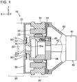
FIG. 1 is a longitudinal sectional view of an electric motor adapted for use in a hybrid power unit and having a structure for mounting a rotation sensor according to a first embodiment of the present invention; -
FIG. 2 is a perspective view of the electric motor and an end plate ofFIG. 1 ; -
FIG. 3 is an exploded perspective view showing an end plate and a stator of the rotation sensor of the electric motor ofFIG. 2 ; -
FIG. 4 is an enlarged front view of the rotation sensor ofFIG. 3 ; -
FIG. 5 is a partially-enlarged sectional view of the structure for mounting the rotation sensor ofFIG. 1 ; -
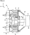
FIG. 6 is a longitudinal sectional view of an electric motor adapted for use in a hybrid power unit and having a structure for mounting a rotation sensor according to a second embodiment of the present invention; -
FIG. 7 is a schematic view illustrating the concept of the structure for mounting the rotation sensor in a hybrid power unit according to the present invention; and -
FIG. 8 is a schematic view illustrating the function of the structure for mounting the rotation sensor in a hybrid power unit according to the present invention. - The following will describe a structure for mounting the rotation sensor in a hybrid power unit as a power resource for vehicles such as a forklift truck and a construction machine according to a first embodiment of the present invention with reference to
FIGS. 1 to 5 . Referring toFIG. 1 , the hybrid power unit is designated byreference numeral 10. Thehybrid power unit 10 includes an engine indicated by 20 and anelectric motor 30. Theelectric motor 30 also serves as a generator. The coordinate system shown in each drawing indicates various directions of thehybrid power unit 10. In the following descriptions, various directions associated with thehybrid power unit 10 will be discussed based on the arrows in the coordinate system. - In
FIG. 1 , theelectric motor 30 is shown, but the detailed illustration of theengine 20 is omitted. Theengine 20 is disposed on one side of theelectric motor 30 in X direction and anoil pump 40 is disposed on the opposite side of theelectric motor 30 from theengine 20. Theelectric motor 30 has arotary shaft 35 that is fixed on acrank shaft 22 of theengine 20. Therotary shaft 35 of theelectric motor 30 is fixed to apump shaft 42 of theoil pump 40 through a connectingmember 44. Thecrank shaft 22 of theengine 20 is rotatably supported bybearings 20a (FIG. 7 ) that are provided in acylinder block 21 of theengine 20. Thepump shaft 42 of theoil pump 40 is rotatably supported by a bearing (not shown) that is provided in apump body 41 of theoil pump 40. Theelectric motor 30 has no bearing. Anaxial hole 35a is formed through the end of therotary shaft 35 of theelectric motor 30 on the side thereof adjacent to theengine 20 in X direction to receive therein anend 22a of thecrank shaft 22 of theengine 20 that is adjacent to theelectric motor 30. Theend 22a of thecrank shaft 22 is fitted in theaxial hole 35a and fixed to therotary shaft 35 of theelectric motor 30. As shown inFIG. 1 , theaxial hole 35a forms a part of the hole formed axially through therotary shaft 35. It is noted that theaxial hole 35a may be in the form of a bottomed hole to receive therein theend 22a of thecrank shaft 22. - The
electric motor 30 is a brushless motor and includes astator 32 fixed on the inner peripheral surface of ahousing 31 and arotor 33 fixed on therotary shaft 35. Therotor 33 which is fixed on therotary shaft 35 is disposed radially inward of thestator 32 and driven to rotate by current supplied through the winding (not shown) ofstator 32 thus serving as an electric motor. When therotor 33 is driven to rotate by thecrank shaft 22 or thepump shaft 42 and accordingly current is flowed in the winding of thestator 32, therotor 33 and thestator 32 serve as a generator. - A
partition wall 37 is disposed at the end of theelectric motor 30 that is adjacent to theoil pump 40 so as to close the interior of theelectric motor 30. Thepartition wall 37 is formed annularly with the outer peripheral surface thereof extending along the outer peripheral surface of theelectric motor 30. The center hole of thepartition wall 37 is closed by the connectingmember 44. Thepartition wall 37 is fixed to thehousing 31 of theelectric motor 30. The connectingmember 44 is fixed to the end of therotary shaft 35 of theelectric motor 30 that is adjacent to theoil pump 40 in X direction. - The
pump body 41 of theoil pump 40 is fixed to thehousing 31 of theelectric motor 30 at the outer periphery thereof with thepartition wall 37 interposed between thehousing 31 and apump support member 43 of theoil pump 40 which is tapered away from thepartition wall 37. The connectingmember 44 is fixed to the end of thepump shaft 42 on the side thereof that is adjacent to theelectric motor 30 in X direction and also to the end of therotary shaft 35 of theelectric motor 30 on the side thereof that is adjacent tooil pump 40. The connectingmember 44 is fixed to therotary shaft 35 by a plurality of bolts 45 (only one bolt shown inFIG. 1 ) arranged along the annular periphery of the end of therotary shaft 35 on the side thereof that is adjacent to theoil pump 40 in X direction. - On the side of the
electric motor 30 that is adjacent to theengine 20 in X direction, anend plate 36 defines the boundary between theelectric motor 30 and theengine 20 and serves as an outer cover of theelectric motor 30. Specifically, theend plate 36 is connected to the outer periphery of thehousing 31 of theelectric motor 30. Theend plate 36 has an axial center hole through which the end of thecrank shaft 22 passes. Referring toFIG. 1 , arotation sensor 50 is constituted by astator 51 that is fixed to the inner peripheral surface of the axial center hole of theend plate 36 that is adjacent to therotary shaft 35 and arotor 52 that is fixed to therotary shaft 35 of theelectric motor 30 at a position opposite to thestator 51. - Referring to
FIG. 4 showing therotation sensor 50 in an enlarged view, thestator 51 of therotation sensor 50 includes anannular core 51a that is formed of a plurality of laminated steel plates and a plurality of windingmembers 51 b disposed on the inner periphery of thecore 51 a and spaced at a predetermined interval in the circumferential direction of theannular core 51a. Therotor 52 of therotation sensor 50 is disposed with a small gap formed between therotor 52 and the windingmembers 51 b. As with thestator 51, therotor 52 is formed in an annular shape. Therotor 52 has in the outer periphery thereof a plurality ofprojections 52a formed facing the respective windingmembers 51 b of thestator 51. - Though the detailed illustration of the winding
member 51 b is omitted in the drawing, two different types of wires are wound in layers. One is an exciting winding to excite thecore 51 a of the windingmembers 51 b of thestator 51. The other is a detection winding to detect a change of density of magnetic flux of thecore 51 a. When current is flowed in the exciting winding of the windingmembers 51 b, thecore 51 a is excited. As therotor 52 is rotated with therotary shaft 35 of theelectric motor 30 and theprojections 52a are moved circumferentially of and relative to thestator 51, the density of magnetic flux of thecore 51 a in thewinding members 51 b is changed in response to a change of the position of theprojections 52a relative to the windingmembers 51 b. Such change is detected in terms of a voltage across the detection windings of the respective windingmembers 51 b as a detection signal. The detection signal is supplied to the control circuit (not shown) of theelectric motor 30 through the terminal (not shown) in aterminal box 51e and anoutput signal line 51f and used as rotation data of therotary shaft 35 of theelectric motor 30. The exciting current flowing in the exciting winding of the windingmembers 51 b is supplied from the control circuit of theelectric motor 30 through the excitingcurrent line 51 g. - The
stator 51 has therethrough threeelongated holes 51 c that are formed in the shape of a circular arc coaxial with thestator 51. The threeelongated holes 51 c are disposed circumferentially spaced away from each other in thestator 51. A pair of engagingportions 51 d is formed through thestator 51 at positions adjacent to the opposite ends of eachelongated hole 51c in the peripheral direction of thestator 51. The engagingportion 51d is opened at the outer peripheral edge of thestator 51. - As shown in
FIGS. 3 and5 , thestator 51 of therotation sensor 50 is fitted in arecess 36d formed in the center of theend plate 36 at a position that is adjacent to theelectric motor 30 in X direction and fixed to theend plate 36. Therecess 36d is formed to fit the shape and size of the outer shape of thestator 51. A mountingplate 53 is set in contact with the side surface of thestator 51 that is adjacent to theelectric motor 30 in X direction. The mountingplate 53 is formed to have a shape and size that correspond to the shape and a size of a part of the core 51 a of thestator 51 except the windingmembers 51 b. The mountingplate 53 is formed by removing part of the annular shape of the mountingplate 53 so as to prevent interference of the mountingplate 53 with theterminal box 51e on thecore 51a. Three holes (not shown) are formed through the mountingplate 53 at positions corresponding to the respectiveelongated holes 51 c of thestator 51 and nuts 53a are welded to the mountingplate 53 at positions of the respective holes. - As shown in
FIGS. 2 and3 , theend plate 36 has therethrough threebolt holes 36a at positions corresponding to the threeelongated holes 51c of thestator 51. Abolt 54 is inserted through eachbolt hole 36a and eachelongated hole 51 c of thestator 51 and screwed in the threaded hole in eachnut 53a of the mountingplate 53. - Specifically, with the
stator 51 and the mountingplate 53 fitted in therecess 36d of theend plate 36, thebolts 54 are inserted into therespective bolt holes 36a from the side of theend plate 36 that is adjacent to theengine 20. Then, thebolts 54 are inserted through theelongated holes 51c and screwed through the threaded holes of the nuts 53a of the mountingplate 53, respectively. Thus, thestator 51 is fixed to theend plate 36. Thestator 51 which is fitted in therecess 36d may be fixed to theend plate 36 at the center thereof without being offset in the radial direction relative to theend plate 36. However, theelongated hole 51c formed through thestator 51 makes possible adjustment of the angular position of thestator 51 relative to theend plate 36 with thebolts 54 loosened. - An adjust
hole 36b is formed through theend plate 36 at a position adjacent to one of thebolt holes 36a. In adjusting the angular position of thestator 51, a needle-shaped tool is inserted through the adjusthole 36b until the tip end of the tool is engaged with the engagingportion 51 d of thestator 51 and thestator 51 is rotated by using the tool. For the adjustment of thestator 51, the bolt 54s need be loosened from the side of theend plate 36 that is adjacent to theengine 20 in X direction. That is, loosening thebolt 54 and rotating thestator 51 with the tool inserted through the adjusthole 36b may be performed from the same side of theend plate 36 in X direction. It is noted that the illustration of the structure for fixing thestator 51 by thebolts 54 is omitted inFIG. 1 . - A pair of
pin holes 36c is formed through theend plate 36 at positions outward of thebolt holes 36a in Y direction. Though not shown in the drawing, thecylinder block 21 of theengine 20 is provided on the side thereof adjacent to theelectric motor 30 with a pair of locating pins at positions corresponding to the pin holes 36c of theend plate 36. By inserting the paired locating pins in the pairedpin holes 36c of theend plate 36, theend plate 36 is positioned correctly relative to thecylinder block 21. - As shown in
FIG. 5 , a stepped portion 35b that is formed in such a way that the diameter of therotary shaft 35 is reduced, is formed at the end of therotary shaft 35 adjacent to theend plate 36 in X direction. Therotor 52 of therotation sensor 50 is fitted on therotary shaft 35 with the inner periphery of therotor 52 in contact with the stepped portion 35b. A pressing ring 55 is shrink-fitted on the stepped portion 35b of therotary shaft 35. As with therotor 52, the pressing ring 55 has an annular plate shape. After shrink-fitted, the inner diameter of the pressing ring 55 becomes substantially the same as that of therotor 52. The pressing ring 55 is smaller in the outer diameter than therotor 52. Therotor 52 thus fixed on therotary shaft 35 is positioned facing the inner periphery of thestator 51. - Referring to
FIG. 7 showing schematically the mounting of therotation sensor 50 according to the first embodiment of the present invention, thecrank shaft 22 of theengine 20 is supported at the opposite ends thereof by the pairedbearings 20a, whereas theelectric motor 30 has no bearing. Therotary shaft 35 of therotor 33 which is connected to thecrank shaft 22 is supported in a cantilever manner. Thestator 51 of therotation sensor 50 is fixed to theend plate 36 that is integrated with thestator 32 of theelectric motor 30. Therotor 52 of therotation sensor 50 is fixed on therotary shaft 35 of theelectric motor 30 on the side of theelectric motor 30 that is adjacent to theengine 20 in X direction. -
FIG. 8 shows function of theelectric motor 30 according to the first embodiment of the present invention. As described above, in the case that theelectric motor 30 has no bearing, misalignment of therotor 33 and therotary shaft 35 of theelectric motor 30 relative to thecrank shaft 22 of theengine 20 may occur due to production tolerance. Specifically, as shown inFIG. 8 , theaxis 35c of therotary shaft 35 fails to be aligned with theaxis 22b of thecrank shaft 22. Then, the spaced distance between thestator 51 and therotor 52 of therotation sensor 50 becomes irregular, with the result that detection accuracy of therotation sensor 50 is reduced. In the case of such poor alignment of therotary shaft 35 of theelectric motor 30, the variation of the spaced distance between thestator 51 and therotor 52 of therotation sensor 50 is greater when therotation sensor 50 is disposed on the distal end of therotary shaft 35 as indicated by phantom lines than when therotation sensor 50 is disposed on the proximal end of therotary shaft 35 as indicated by solid lines. It is noted that the misalignment is shown exaggeratedly inFIG. 8 for better understanding of the present invention. - As is apparent from the foregoing description, the
rotation sensor 50 of the present embodiment is less susceptible to the influence of misalignment of therotary shaft 35 with respect to thecrank shaft 22. As a result, decrease of the detection accuracy of therotation sensor 50 due to misalignment of therotary shaft 35 of theelectric motor 30 may be prevented. - The
stator 51 of therotation sensor 50 is fitted and fixed in therecess 36d of theend plate 36. Though thestator 51 is movable only in the peripheral direction for the angular position adjustment thereof, thestator 51 is securely fixed at a position that is determined by therecess 36d without being allowed to move in any other directions. The end of thecrank shaft 22 that is adjacent to theelectric motor 30 in X direction is fitted to theaxial hole 35a of therotary shaft 35 of theelectric motor 30. That is, therotor 52 of therotation sensor 50 is fixed on therotary shaft 35 of theelectric motor 30 and hence fixed on thecrank shaft 22. Therefore, decrease of the detection accuracy of therotation sensor 50 by the misalignment of therotary shaft 35 of theelectric motor 30 may be prevented. - Referring to
FIG. 6 , there is shown a structure for mounting a rotation sensor in a hybrid power unit according to a second embodiment of the present invention. The second embodiment differs from the first embodiment in that arotor 52A of therotation sensor 50A is disposed radially outward of thestator 51A of therotation sensor 50A. The same reference numerals will be used to denote those components or elements which correspond to the counterparts of the first embodiment and the description thereof will not be reiterated. - In the second embodiment of the present invention, the
stator 51A of therotation sensor 50A has on the outer peripheral side thereof a winding member and is fixed to theend plate 36 on the inner peripheral side thereof. Therotor 52A is fixed to the end of a flange portion 34 extending radially outward from therotary shaft 35. Specifically, therotor 52A is fixed to the top of the flange portion 34 on the radially inner side thereof so as to face thestator 51A. The manner in which thestator 51A is fixed to theend plate 36 and therotor 52A is fixed to theend plate 36 is substantially the same as the manner in which thestator 51 is fixed to theend plate 36 and therotor 52 is fixed to therotary shaft 35 in the first embodiment of the present invention. - As with the first embodiment, the
stator 51A of therotation sensor 50A of the second embodiment is fixed to theend plate 36 and therotor 52A of therotation sensor 50A is fixed to the flange portion 34 so as to face thestator 51A on the side of theelectric motor 30 that is adjacent to theengine 20. Therefore, therotation sensor 50A is less susceptible to the influence of misalignment of therotary shaft 35 with respect to thecrank shaft 22, as compared with a structure in which therotation sensor 50A is fixed at a position that is remote from thecrank shaft 22 supported by thebearing 20a. As a result, decrease of the detection accuracy of therotation sensor 50A due to misalignment of therotary shaft 35 of theelectric motor 30 may be prevented. - While the present invention has been described in terms of specific embodiments, the invention can be practiced with modification within the spirit and scope of the invention. For example, though in the above-described embodiments, the crank shaft of the engine and the rotary shaft of the electric motor are connected to the oil pump to convert the output power of the hybrid power unit to hydraulic pressure, the output of the hybrid power unit may be used directly as a power source. Though in the above-described embodiments, the hybrid power unit is used as a power source for a vehicle such as a forklift truck and a construction machine, the hybrid power unit may be used as a power source for a passenger car.
- In the present invention, the rotation sensor may be a type detecting change of magnetic field caused by the rotation of the rotor or may be a photo coupler. In this case, the electric motor also serves as a generator.
- In the present invention, the mounting plate may be integrally formed to be an annular shape in accordance with the annular stator or may be formed to be a shape corresponding to a part of the annular stator. In the latter case, the plural mounting plates may be provided along the annular stator. To fix the mounting plate and the end plate with the bolt, the external thread as a bolt may be fastened with the internal thread, the bolt may be fastened with the nut welded to the end plate or the nut may be fastened with the bolt welded in the end plate. The number of the bolt may be plural. The adjust hole may be single, but the plural adjust holes may be formed along the annular stator.
- In the present invention, the stator of the rotation sensor may be fixed to the end plate by fixing the mounting plate to the end plate by the bolts. Therefore, the bolts can be fastened from the side of the end plate adjacent to the engine. The angular position of the stator of the rotation sensor can be adjusted from the side of the end plate adjacent to the engine by rotating the stator of the rotation sensor through the adjust hole. After the bolts are loosened from the side of the end plate adjacent to the engine, the angular positon of the stator of the rotation sensor can be adjusted. After finishing adjustment, the stator can be fixed to the end plate by fastening the bolts. Thus, the angular position of the stator of the rotation sensor can be adjusted easily from the side of the end plate adjacent to the engine.
Claims (3)
- A structure for mounting a rotation sensor (50, 50A) to an electric motor (30) in a hybrid power unit (10) including both an engine (20) and the electric motor (30), wherein the electric motor (30) includes a rotary shaft (35) that is supported in a cantilever manner by a crank shaft (22) of the engine (20), characterized by:an end plate (36) defining a boundary between the engine (20) and the electric motor (30) and serving as an outer cover for the electric motor (30); andthe rotation sensor (50, 50A) comprising:a stator (51, 51 A) fixed on the end plate (36); anda rotor (52, 52A) fixed on the rotary shaft (35) facing the stator (51, 51A).
- The structure for mounting the rotation sensor (50, 50A) according to claim 1, characterized in that a mounting plate (53) is provided to hold the stator (51, 51 A) between the mounting plate (53) and the end plate (36), and that a bolt (54) is screwed in the mounting plate (53) through the end plate (36) and the stator (51, 51A), wherein an adjust hole (36b) is formed through the end plate (36) at a position where an angular position of the stator (51, 51A) is adjustable around an axis (35c) of the rotary shaft (35) from an engine side of the end plate (36).
- The structure for mounting the rotation sensor (50, 50A) according to claim 1 or 2, characterized in that a recess (36d) is formed in a side of the end plate (36) adjacent to the electric motor (30) to fit a shape and size of the stator (51) of the rotation sensor (50), wherein the stator (51) of the rotation sensor (50) is fixedly fitted in the recess (36d), wherein an axial hole (35a) is formed in an end of the rotary shaft (35) of the electric motor (30) to receive an end of the crank shaft (22) of the engine (20), wherein the end of the crank shaft (22) is fixedly fitted in the axial hole (35a), and wherein the rotor (52) of the rotation sensor (50) is fixed on an outer periphery of the rotary shaft (35) of the electric motor (30) and positioned facing an inner periphery of the stator (51) of the rotation sensor (50).
Applications Claiming Priority (1)
| Application Number | Priority Date | Filing Date | Title |
|---|---|---|---|
| JP2016069986A JP6428696B2 (en) | 2016-03-31 | 2016-03-31 | Rotation sensor mounting structure for hybrid power unit motor |
Publications (2)
| Publication Number | Publication Date |
|---|---|
| EP3225447A1 true EP3225447A1 (en) | 2017-10-04 |
| EP3225447B1 EP3225447B1 (en) | 2018-09-26 |
Family
ID=58454902
Family Applications (1)
| Application Number | Title | Priority Date | Filing Date |
|---|---|---|---|
| EP17163276.3A Active EP3225447B1 (en) | 2016-03-31 | 2017-03-28 | Hybrid power unit |
Country Status (2)
| Country | Link |
|---|---|
| EP (1) | EP3225447B1 (en) |
| JP (1) | JP6428696B2 (en) |
Cited By (5)
| Publication number | Priority date | Publication date | Assignee | Title |
|---|---|---|---|---|
| CN110071605A (en) * | 2018-01-23 | 2019-07-30 | 赛卓电子科技(上海)有限公司 | Electric motor mounting structure with induction rotary transformer |
| CN110571976A (en) * | 2019-09-18 | 2019-12-13 | 精进电动科技股份有限公司 | A kind of engine and motor assembly |
| ES2798048A1 (en) * | 2020-10-01 | 2020-12-04 | Univ Madrid Politecnica | ROTARY SENSOR FOR MEASURING ALTERNATING CURRENT AND / OR DIRECT CURRENT IN ROTARY MACHINES |
| US20220001853A1 (en) * | 2020-07-01 | 2022-01-06 | Mazda Motor Corporation | Vehicle |
| CN117087440A (en) * | 2023-09-21 | 2023-11-21 | 小米汽车科技有限公司 | Powertrain, chassis and vehicle |
Families Citing this family (2)
| Publication number | Priority date | Publication date | Assignee | Title |
|---|---|---|---|---|
| JP2020124015A (en) * | 2019-01-29 | 2020-08-13 | 本田技研工業株式会社 | Rotary electric machine unit and resolver stator |
| KR102912215B1 (en) * | 2024-04-11 | 2026-01-13 | 현대트랜시스 주식회사 | Motor device for vehicle |
Citations (7)
| Publication number | Priority date | Publication date | Assignee | Title |
|---|---|---|---|---|
| JP2000224797A (en) * | 1999-01-29 | 2000-08-11 | Mitsubishi Automob Eng Co Ltd | Motor supporting structure |
| JP2005057832A (en) * | 2003-08-05 | 2005-03-03 | Honda Motor Co Ltd | Electric motor and hybrid vehicle equipped with the same |
| JP2005080430A (en) * | 2003-09-01 | 2005-03-24 | Tamagawa Seiki Co Ltd | Resolver built-in motor |
| WO2005105507A1 (en) | 2004-04-28 | 2005-11-10 | Aisin Aw Co., Ltd | Drive device for hybrid vehicle |
| JP2008143439A (en) * | 2006-12-13 | 2008-06-26 | Mitsuba Corp | Hybrid car |
| US20090227416A1 (en) * | 2006-03-23 | 2009-09-10 | Toyota Jidosha Kabushiki Kaisha | Power transmission device and method of assembling the same |
| US20150239332A1 (en) * | 2012-01-20 | 2015-08-27 | Toyota Jidosha Kabushiki Kaisha | Vehicle drive device |
Family Cites Families (5)
| Publication number | Priority date | Publication date | Assignee | Title |
|---|---|---|---|---|
| JP3591354B2 (en) * | 1999-01-29 | 2004-11-17 | 三菱自動車エンジニアリング株式会社 | Motor support structure |
| JP2007336714A (en) * | 2006-06-15 | 2007-12-27 | Toyota Motor Corp | Resolver sensor fixed structure |
| JP2008145153A (en) * | 2006-12-07 | 2008-06-26 | Toyota Motor Corp | Rotating electric machine |
| GB201117931D0 (en) * | 2011-10-18 | 2011-11-30 | Cummins Generator Technologies | Housing arrangement for an electrical machine |
| JP5728458B2 (en) * | 2012-11-05 | 2015-06-03 | 本田技研工業株式会社 | Drive unit with rotation detector |
-
2016
- 2016-03-31 JP JP2016069986A patent/JP6428696B2/en active Active
-
2017
- 2017-03-28 EP EP17163276.3A patent/EP3225447B1/en active Active
Patent Citations (7)
| Publication number | Priority date | Publication date | Assignee | Title |
|---|---|---|---|---|
| JP2000224797A (en) * | 1999-01-29 | 2000-08-11 | Mitsubishi Automob Eng Co Ltd | Motor supporting structure |
| JP2005057832A (en) * | 2003-08-05 | 2005-03-03 | Honda Motor Co Ltd | Electric motor and hybrid vehicle equipped with the same |
| JP2005080430A (en) * | 2003-09-01 | 2005-03-24 | Tamagawa Seiki Co Ltd | Resolver built-in motor |
| WO2005105507A1 (en) | 2004-04-28 | 2005-11-10 | Aisin Aw Co., Ltd | Drive device for hybrid vehicle |
| US20090227416A1 (en) * | 2006-03-23 | 2009-09-10 | Toyota Jidosha Kabushiki Kaisha | Power transmission device and method of assembling the same |
| JP2008143439A (en) * | 2006-12-13 | 2008-06-26 | Mitsuba Corp | Hybrid car |
| US20150239332A1 (en) * | 2012-01-20 | 2015-08-27 | Toyota Jidosha Kabushiki Kaisha | Vehicle drive device |
Cited By (9)
| Publication number | Priority date | Publication date | Assignee | Title |
|---|---|---|---|---|
| CN110071605A (en) * | 2018-01-23 | 2019-07-30 | 赛卓电子科技(上海)有限公司 | Electric motor mounting structure with induction rotary transformer |
| CN110071605B (en) * | 2018-01-23 | 2020-12-22 | 赛卓电子科技(上海)有限公司 | Motor mounting structure with electromagnetic induction type rotary transformer |
| CN110571976A (en) * | 2019-09-18 | 2019-12-13 | 精进电动科技股份有限公司 | A kind of engine and motor assembly |
| EP3796524A1 (en) * | 2019-09-18 | 2021-03-24 | Jing-Jin Electric Technologies Co., Ltd | Engine-and-electric-machine assembly |
| US11554655B2 (en) | 2019-09-18 | 2023-01-17 | Jing-Jin Electric Technologies Co., Ltd. | Engine-and-electric-machine assembly |
| US20220001853A1 (en) * | 2020-07-01 | 2022-01-06 | Mazda Motor Corporation | Vehicle |
| US11608052B2 (en) * | 2020-07-01 | 2023-03-21 | Mazda Motor Corporation | Vehicle |
| ES2798048A1 (en) * | 2020-10-01 | 2020-12-04 | Univ Madrid Politecnica | ROTARY SENSOR FOR MEASURING ALTERNATING CURRENT AND / OR DIRECT CURRENT IN ROTARY MACHINES |
| CN117087440A (en) * | 2023-09-21 | 2023-11-21 | 小米汽车科技有限公司 | Powertrain, chassis and vehicle |
Also Published As
| Publication number | Publication date |
|---|---|
| EP3225447B1 (en) | 2018-09-26 |
| JP2017184507A (en) | 2017-10-05 |
| JP6428696B2 (en) | 2018-11-28 |
Similar Documents
| Publication | Publication Date | Title |
|---|---|---|
| EP3225447B1 (en) | Hybrid power unit | |
| JP5786642B2 (en) | Stator fixing structure | |
| EP2487377B1 (en) | Resolver and resolver-rolling bearing unit | |
| EP2546963A2 (en) | Motor | |
| US9444293B2 (en) | Rotary electric machine | |
| US8232693B2 (en) | Resolver with locating feature | |
| US20190077440A1 (en) | Motor and electric power steering device | |
| US10666103B2 (en) | Rotor of rotating electric machine | |
| US11539264B2 (en) | Vehicle electric motor | |
| US7030607B2 (en) | Variable reluctance-type resolver | |
| JP6357738B2 (en) | Method for assembling rotation angle detector | |
| KR102792937B1 (en) | Electric machine assembly and method for locking rotor to stator | |
| JP6540704B2 (en) | Method of manufacturing direct drive motor, and jig | |
| US8987954B2 (en) | On-vehicle motor including detector for detecting state of motor | |
| CN109937522B (en) | Stator of rotating electrical machine and method of manufacturing the same | |
| JP2013093985A (en) | Stator fixing structure | |
| JP2013162730A (en) | Rotary electric machine | |
| US9784556B2 (en) | Rotation detector detecting rotation of rotating machine and system provided with rotation detector | |
| US11038392B2 (en) | Electric motor | |
| US9488462B2 (en) | Structure for mounting resolver | |
| US20100072864A1 (en) | Motor Assembly with Sensor Target on Motor Rotor and Method of Forming Same | |
| JP2019205260A (en) | Stator and rotary electric machine | |
| JP2013027122A (en) | Resolver and manufacturing method therefor, and rolling bearing device with resolver | |
| JP2013093984A (en) | Structure for fixing stator | |
| JP2013024690A (en) | Resolver and method for assembling the same |
Legal Events
| Date | Code | Title | Description |
|---|---|---|---|
| PUAI | Public reference made under article 153(3) epc to a published international application that has entered the european phase |
Free format text: ORIGINAL CODE: 0009012 |
|
| STAA | Information on the status of an ep patent application or granted ep patent |
Free format text: STATUS: REQUEST FOR EXAMINATION WAS MADE |
|
| 17P | Request for examination filed |
Effective date: 20170328 |
|
| AK | Designated contracting states |
Kind code of ref document: A1 Designated state(s): AL AT BE BG CH CY CZ DE DK EE ES FI FR GB GR HR HU IE IS IT LI LT LU LV MC MK MT NL NO PL PT RO RS SE SI SK SM TR |
|
| AX | Request for extension of the european patent |
Extension state: BA ME |
|
| GRAP | Despatch of communication of intention to grant a patent |
Free format text: ORIGINAL CODE: EPIDOSNIGR1 |
|
| STAA | Information on the status of an ep patent application or granted ep patent |
Free format text: STATUS: GRANT OF PATENT IS INTENDED |
|
| RIC1 | Information provided on ipc code assigned before grant |
Ipc: B60K 6/485 20071001AFI20180424BHEP Ipc: H02K 11/225 20160101ALI20180424BHEP Ipc: H02K 7/00 20060101ALI20180424BHEP Ipc: B60K 6/40 20071001ALI20180424BHEP |
|
| INTG | Intention to grant announced |
Effective date: 20180524 |
|
| GRAS | Grant fee paid |
Free format text: ORIGINAL CODE: EPIDOSNIGR3 |
|
| GRAA | (expected) grant |
Free format text: ORIGINAL CODE: 0009210 |
|
| STAA | Information on the status of an ep patent application or granted ep patent |
Free format text: STATUS: THE PATENT HAS BEEN GRANTED |
|
| AK | Designated contracting states |
Kind code of ref document: B1 Designated state(s): AL AT BE BG CH CY CZ DE DK EE ES FI FR GB GR HR HU IE IS IT LI LT LU LV MC MK MT NL NO PL PT RO RS SE SI SK SM TR |
|
| REG | Reference to a national code |
Ref country code: GB Ref legal event code: FG4D |
|
| REG | Reference to a national code |
Ref country code: CH Ref legal event code: EP |
|
| REG | Reference to a national code |
Ref country code: CH Ref legal event code: NV Representative=s name: NOVAGRAAF INTERNATIONAL SA, CH Ref country code: AT Ref legal event code: REF Ref document number: 1045576 Country of ref document: AT Kind code of ref document: T Effective date: 20181015 |
|
| REG | Reference to a national code |
Ref country code: IE Ref legal event code: FG4D |
|
| REG | Reference to a national code |
Ref country code: DE Ref legal event code: R096 Ref document number: 602017000504 Country of ref document: DE |
|
| REG | Reference to a national code |
Ref country code: SE Ref legal event code: TRGR |
|
| REG | Reference to a national code |
Ref country code: NL Ref legal event code: MP Effective date: 20180926 |
|
| PG25 | Lapsed in a contracting state [announced via postgrant information from national office to epo] |
Ref country code: BG Free format text: LAPSE BECAUSE OF FAILURE TO SUBMIT A TRANSLATION OF THE DESCRIPTION OR TO PAY THE FEE WITHIN THE PRESCRIBED TIME-LIMIT Effective date: 20181226 Ref country code: FI Free format text: LAPSE BECAUSE OF FAILURE TO SUBMIT A TRANSLATION OF THE DESCRIPTION OR TO PAY THE FEE WITHIN THE PRESCRIBED TIME-LIMIT Effective date: 20180926 Ref country code: RS Free format text: LAPSE BECAUSE OF FAILURE TO SUBMIT A TRANSLATION OF THE DESCRIPTION OR TO PAY THE FEE WITHIN THE PRESCRIBED TIME-LIMIT Effective date: 20180926 Ref country code: LT Free format text: LAPSE BECAUSE OF FAILURE TO SUBMIT A TRANSLATION OF THE DESCRIPTION OR TO PAY THE FEE WITHIN THE PRESCRIBED TIME-LIMIT Effective date: 20180926 Ref country code: NO Free format text: LAPSE BECAUSE OF FAILURE TO SUBMIT A TRANSLATION OF THE DESCRIPTION OR TO PAY THE FEE WITHIN THE PRESCRIBED TIME-LIMIT Effective date: 20181226 Ref country code: GR Free format text: LAPSE BECAUSE OF FAILURE TO SUBMIT A TRANSLATION OF THE DESCRIPTION OR TO PAY THE FEE WITHIN THE PRESCRIBED TIME-LIMIT Effective date: 20181227 |
|
| REG | Reference to a national code |
Ref country code: CH Ref legal event code: PK Free format text: BERICHTIGUNGEN |
|
| REG | Reference to a national code |
Ref country code: LT Ref legal event code: MG4D |
|
| RIC2 | Information provided on ipc code assigned after grant |
Ipc: H02K 7/00 20060101ALI20180424BHEP Ipc: B60K 6/485 20071001AFI20180424BHEP Ipc: B60K 6/40 20071001ALI20180424BHEP Ipc: H02K 11/225 20160101ALI20180424BHEP |
|
| PG25 | Lapsed in a contracting state [announced via postgrant information from national office to epo] |
Ref country code: LV Free format text: LAPSE BECAUSE OF FAILURE TO SUBMIT A TRANSLATION OF THE DESCRIPTION OR TO PAY THE FEE WITHIN THE PRESCRIBED TIME-LIMIT Effective date: 20180926 Ref country code: HR Free format text: LAPSE BECAUSE OF FAILURE TO SUBMIT A TRANSLATION OF THE DESCRIPTION OR TO PAY THE FEE WITHIN THE PRESCRIBED TIME-LIMIT Effective date: 20180926 Ref country code: AL Free format text: LAPSE BECAUSE OF FAILURE TO SUBMIT A TRANSLATION OF THE DESCRIPTION OR TO PAY THE FEE WITHIN THE PRESCRIBED TIME-LIMIT Effective date: 20180926 |
|
| REG | Reference to a national code |
Ref country code: AT Ref legal event code: MK05 Ref document number: 1045576 Country of ref document: AT Kind code of ref document: T Effective date: 20180926 |
|
| PG25 | Lapsed in a contracting state [announced via postgrant information from national office to epo] |
Ref country code: NL Free format text: LAPSE BECAUSE OF FAILURE TO SUBMIT A TRANSLATION OF THE DESCRIPTION OR TO PAY THE FEE WITHIN THE PRESCRIBED TIME-LIMIT Effective date: 20180926 Ref country code: CZ Free format text: LAPSE BECAUSE OF FAILURE TO SUBMIT A TRANSLATION OF THE DESCRIPTION OR TO PAY THE FEE WITHIN THE PRESCRIBED TIME-LIMIT Effective date: 20180926 Ref country code: IS Free format text: LAPSE BECAUSE OF FAILURE TO SUBMIT A TRANSLATION OF THE DESCRIPTION OR TO PAY THE FEE WITHIN THE PRESCRIBED TIME-LIMIT Effective date: 20190126 Ref country code: PL Free format text: LAPSE BECAUSE OF FAILURE TO SUBMIT A TRANSLATION OF THE DESCRIPTION OR TO PAY THE FEE WITHIN THE PRESCRIBED TIME-LIMIT Effective date: 20180926 Ref country code: RO Free format text: LAPSE BECAUSE OF FAILURE TO SUBMIT A TRANSLATION OF THE DESCRIPTION OR TO PAY THE FEE WITHIN THE PRESCRIBED TIME-LIMIT Effective date: 20180926 Ref country code: AT Free format text: LAPSE BECAUSE OF FAILURE TO SUBMIT A TRANSLATION OF THE DESCRIPTION OR TO PAY THE FEE WITHIN THE PRESCRIBED TIME-LIMIT Effective date: 20180926 Ref country code: EE Free format text: LAPSE BECAUSE OF FAILURE TO SUBMIT A TRANSLATION OF THE DESCRIPTION OR TO PAY THE FEE WITHIN THE PRESCRIBED TIME-LIMIT Effective date: 20180926 |
|
| PG25 | Lapsed in a contracting state [announced via postgrant information from national office to epo] |
Ref country code: SM Free format text: LAPSE BECAUSE OF FAILURE TO SUBMIT A TRANSLATION OF THE DESCRIPTION OR TO PAY THE FEE WITHIN THE PRESCRIBED TIME-LIMIT Effective date: 20180926 Ref country code: SK Free format text: LAPSE BECAUSE OF FAILURE TO SUBMIT A TRANSLATION OF THE DESCRIPTION OR TO PAY THE FEE WITHIN THE PRESCRIBED TIME-LIMIT Effective date: 20180926 Ref country code: PT Free format text: LAPSE BECAUSE OF FAILURE TO SUBMIT A TRANSLATION OF THE DESCRIPTION OR TO PAY THE FEE WITHIN THE PRESCRIBED TIME-LIMIT Effective date: 20190126 |
|
| REG | Reference to a national code |
Ref country code: DE Ref legal event code: R097 Ref document number: 602017000504 Country of ref document: DE |
|
| PG25 | Lapsed in a contracting state [announced via postgrant information from national office to epo] |
Ref country code: ES Free format text: LAPSE BECAUSE OF FAILURE TO SUBMIT A TRANSLATION OF THE DESCRIPTION OR TO PAY THE FEE WITHIN THE PRESCRIBED TIME-LIMIT Effective date: 20180926 Ref country code: DK Free format text: LAPSE BECAUSE OF FAILURE TO SUBMIT A TRANSLATION OF THE DESCRIPTION OR TO PAY THE FEE WITHIN THE PRESCRIBED TIME-LIMIT Effective date: 20180926 |
|
| PLBE | No opposition filed within time limit |
Free format text: ORIGINAL CODE: 0009261 |
|
| STAA | Information on the status of an ep patent application or granted ep patent |
Free format text: STATUS: NO OPPOSITION FILED WITHIN TIME LIMIT |
|
| 26N | No opposition filed |
Effective date: 20190627 |
|
| PG25 | Lapsed in a contracting state [announced via postgrant information from national office to epo] |
Ref country code: SI Free format text: LAPSE BECAUSE OF FAILURE TO SUBMIT A TRANSLATION OF THE DESCRIPTION OR TO PAY THE FEE WITHIN THE PRESCRIBED TIME-LIMIT Effective date: 20180926 Ref country code: MC Free format text: LAPSE BECAUSE OF FAILURE TO SUBMIT A TRANSLATION OF THE DESCRIPTION OR TO PAY THE FEE WITHIN THE PRESCRIBED TIME-LIMIT Effective date: 20180926 |
|
| PG25 | Lapsed in a contracting state [announced via postgrant information from national office to epo] |
Ref country code: LU Free format text: LAPSE BECAUSE OF NON-PAYMENT OF DUE FEES Effective date: 20190328 |
|
| REG | Reference to a national code |
Ref country code: BE Ref legal event code: MM Effective date: 20190331 |
|
| PG25 | Lapsed in a contracting state [announced via postgrant information from national office to epo] |
Ref country code: IE Free format text: LAPSE BECAUSE OF NON-PAYMENT OF DUE FEES Effective date: 20190328 |
|
| PG25 | Lapsed in a contracting state [announced via postgrant information from national office to epo] |
Ref country code: BE Free format text: LAPSE BECAUSE OF NON-PAYMENT OF DUE FEES Effective date: 20190331 |
|
| PG25 | Lapsed in a contracting state [announced via postgrant information from national office to epo] |
Ref country code: TR Free format text: LAPSE BECAUSE OF FAILURE TO SUBMIT A TRANSLATION OF THE DESCRIPTION OR TO PAY THE FEE WITHIN THE PRESCRIBED TIME-LIMIT Effective date: 20180926 |
|
| PG25 | Lapsed in a contracting state [announced via postgrant information from national office to epo] |
Ref country code: MT Free format text: LAPSE BECAUSE OF NON-PAYMENT OF DUE FEES Effective date: 20190328 |
|
| PG25 | Lapsed in a contracting state [announced via postgrant information from national office to epo] |
Ref country code: CY Free format text: LAPSE BECAUSE OF FAILURE TO SUBMIT A TRANSLATION OF THE DESCRIPTION OR TO PAY THE FEE WITHIN THE PRESCRIBED TIME-LIMIT Effective date: 20180926 |
|
| PG25 | Lapsed in a contracting state [announced via postgrant information from national office to epo] |
Ref country code: HU Free format text: LAPSE BECAUSE OF FAILURE TO SUBMIT A TRANSLATION OF THE DESCRIPTION OR TO PAY THE FEE WITHIN THE PRESCRIBED TIME-LIMIT; INVALID AB INITIO Effective date: 20170328 |
|
| PG25 | Lapsed in a contracting state [announced via postgrant information from national office to epo] |
Ref country code: MK Free format text: LAPSE BECAUSE OF FAILURE TO SUBMIT A TRANSLATION OF THE DESCRIPTION OR TO PAY THE FEE WITHIN THE PRESCRIBED TIME-LIMIT Effective date: 20180926 |
|
| P01 | Opt-out of the competence of the unified patent court (upc) registered |
Effective date: 20230519 |
|
| REG | Reference to a national code |
Ref country code: DE Ref legal event code: R084 Ref document number: 602017000504 Country of ref document: DE |
|
| REG | Reference to a national code |
Ref country code: GB Ref legal event code: 746 Effective date: 20250127 |
|
| PGFP | Annual fee paid to national office [announced via postgrant information from national office to epo] |
Ref country code: CH Payment date: 20250401 Year of fee payment: 9 |
|
| REG | Reference to a national code |
Ref country code: CH Ref legal event code: U11 Free format text: ST27 STATUS EVENT CODE: U-0-0-U10-U11 (AS PROVIDED BY THE NATIONAL OFFICE) Effective date: 20260401 |
|
| PGFP | Annual fee paid to national office [announced via postgrant information from national office to epo] |
Ref country code: SE Payment date: 20260211 Year of fee payment: 10 |
|
| PGFP | Annual fee paid to national office [announced via postgrant information from national office to epo] |
Ref country code: GB Payment date: 20260209 Year of fee payment: 10 |
|
| PGFP | Annual fee paid to national office [announced via postgrant information from national office to epo] |
Ref country code: DE Payment date: 20260204 Year of fee payment: 10 |
|
| PGFP | Annual fee paid to national office [announced via postgrant information from national office to epo] |
Ref country code: IT Payment date: 20260220 Year of fee payment: 10 |
|
| PGFP | Annual fee paid to national office [announced via postgrant information from national office to epo] |
Ref country code: FR Payment date: 20260209 Year of fee payment: 10 |