EP3225288A1 - Racquet, in particular padel racquet structure - Google Patents
Racquet, in particular padel racquet structure Download PDFInfo
- Publication number
- EP3225288A1 EP3225288A1 EP17156152.5A EP17156152A EP3225288A1 EP 3225288 A1 EP3225288 A1 EP 3225288A1 EP 17156152 A EP17156152 A EP 17156152A EP 3225288 A1 EP3225288 A1 EP 3225288A1
- Authority
- EP
- European Patent Office
- Prior art keywords
- racket
- core
- additional reinforcing
- racket according
- additional
- Prior art date
- Legal status (The legal status is an assumption and is not a legal conclusion. Google has not performed a legal analysis and makes no representation as to the accuracy of the status listed.)
- Granted
Links
- 230000003014 reinforcing effect Effects 0.000 claims abstract description 60
- 230000002093 peripheral effect Effects 0.000 claims abstract description 23
- 239000010410 layer Substances 0.000 claims description 25
- 238000000465 moulding Methods 0.000 claims description 20
- 239000002131 composite material Substances 0.000 claims description 19
- 230000002787 reinforcement Effects 0.000 claims description 17
- 238000004519 manufacturing process Methods 0.000 claims description 8
- 239000000463 material Substances 0.000 claims description 7
- 239000011241 protective layer Substances 0.000 claims description 6
- 239000011162 core material Substances 0.000 description 64
- 239000006260 foam Substances 0.000 description 6
- 239000000835 fiber Substances 0.000 description 5
- 230000007547 defect Effects 0.000 description 4
- 229920005989 resin Polymers 0.000 description 3
- 239000011347 resin Substances 0.000 description 3
- 229920000049 Carbon (fiber) Polymers 0.000 description 2
- 238000004026 adhesive bonding Methods 0.000 description 2
- 239000004760 aramid Substances 0.000 description 2
- 239000004917 carbon fiber Substances 0.000 description 2
- 239000011152 fibreglass Substances 0.000 description 2
- 239000004033 plastic Substances 0.000 description 2
- 229920003023 plastic Polymers 0.000 description 2
- OKTJSMMVPCPJKN-UHFFFAOYSA-N Carbon Chemical compound [C] OKTJSMMVPCPJKN-UHFFFAOYSA-N 0.000 description 1
- 239000005977 Ethylene Substances 0.000 description 1
- -1 Ethylene Vinyl Acetal Chemical class 0.000 description 1
- DHKHKXVYLBGOIT-UHFFFAOYSA-N acetaldehyde Diethyl Acetal Natural products CCOC(C)OCC DHKHKXVYLBGOIT-UHFFFAOYSA-N 0.000 description 1
- 239000000853 adhesive Substances 0.000 description 1
- 230000001070 adhesive effect Effects 0.000 description 1
- XAGFODPZIPBFFR-UHFFFAOYSA-N aluminium Chemical compound [Al] XAGFODPZIPBFFR-UHFFFAOYSA-N 0.000 description 1
- 229910052782 aluminium Inorganic materials 0.000 description 1
- 229920006231 aramid fiber Polymers 0.000 description 1
- 229920003235 aromatic polyamide Polymers 0.000 description 1
- 238000010009 beating Methods 0.000 description 1
- 230000015572 biosynthetic process Effects 0.000 description 1
- 229910052799 carbon Inorganic materials 0.000 description 1
- 239000000470 constituent Substances 0.000 description 1
- 238000005520 cutting process Methods 0.000 description 1
- 238000013016 damping Methods 0.000 description 1
- 238000009826 distribution Methods 0.000 description 1
- 230000000694 effects Effects 0.000 description 1
- 229940082150 encore Drugs 0.000 description 1
- 239000003822 epoxy resin Substances 0.000 description 1
- 239000011521 glass Substances 0.000 description 1
- 239000003365 glass fiber Substances 0.000 description 1
- 238000002347 injection Methods 0.000 description 1
- 239000007924 injection Substances 0.000 description 1
- 239000003973 paint Substances 0.000 description 1
- 229920000647 polyepoxide Polymers 0.000 description 1
- 239000000243 solution Substances 0.000 description 1
- 229920001169 thermoplastic Polymers 0.000 description 1
- 239000004416 thermosoftening plastic Substances 0.000 description 1
- 239000002966 varnish Substances 0.000 description 1
- 229920002554 vinyl polymer Polymers 0.000 description 1
- 230000037303 wrinkles Effects 0.000 description 1
Images


Classifications
-
- A—HUMAN NECESSITIES
- A63—SPORTS; GAMES; AMUSEMENTS
- A63B—APPARATUS FOR PHYSICAL TRAINING, GYMNASTICS, SWIMMING, CLIMBING, OR FENCING; BALL GAMES; TRAINING EQUIPMENT
- A63B59/00—Bats, rackets, or the like, not covered by groups A63B49/00 - A63B57/00
- A63B59/40—Rackets or the like with flat striking surfaces for hitting a ball in the air, e.g. for table tennis
- A63B59/42—Rackets or the like with flat striking surfaces for hitting a ball in the air, e.g. for table tennis with solid surfaces
-
- A—HUMAN NECESSITIES
- A63—SPORTS; GAMES; AMUSEMENTS
- A63B—APPARATUS FOR PHYSICAL TRAINING, GYMNASTICS, SWIMMING, CLIMBING, OR FENCING; BALL GAMES; TRAINING EQUIPMENT
- A63B2102/00—Application of clubs, bats, rackets or the like to the sporting activity ; particular sports involving the use of balls and clubs, bats, rackets, or the like
- A63B2102/08—Paddle tennis, padel tennis or platform tennis
-
- A—HUMAN NECESSITIES
- A63—SPORTS; GAMES; AMUSEMENTS
- A63B—APPARATUS FOR PHYSICAL TRAINING, GYMNASTICS, SWIMMING, CLIMBING, OR FENCING; BALL GAMES; TRAINING EQUIPMENT
- A63B2209/00—Characteristics of used materials
- A63B2209/02—Characteristics of used materials with reinforcing fibres, e.g. carbon, polyamide fibres
Definitions
- the invention relates to a racket, for hitting a ball, and not having a rope. In particular it is intended for Padel's game.
- Padel is a ball game that is played with a racket without ropes, whose striking zone is full or almost full as it may have holes crossing transversely the head of the racket. Padel's game is played on a field separated by a net and surrounded by walls, with the ball bouncing off the ground and bouncing off the walls.
- Padel's racket consists of three parts, which are the head, the heart and the neck.
- the head corresponds to the strike zone of the ball
- the neck is the part that is tightened by the player's hand
- the heart is the area that connects the head to the handle of the racket.
- padel rackets comprise in the striking area or head of the racket, a core covered on each of its two striking faces by a reinforcement generally made of composite material. Furthermore, a generally hollow tube surrounds the head of the racket and the two ends of this tube meet at the handle, as described in document ES 2,395,181 . This hollow tube directly surrounds the periphery of the core of the racket. This tube takes its hollow form during the molding of the racket and in particular through an inflation operation of this tube. This hollow tube has an outer surface forming the perimeter of the head of the racket which reproduces the shape of the mold used during molding. On the other hand, its inner surface in contact with the periphery of the core of the racket is not always regular and can present deformations or folds, which frequently induces defects and damages the resistance of the racket.
- the object of the invention is to provide a particular internal racquet structure for obtaining a tube or tubular element well formed. Another object of the invention makes it possible to increase the resistance of the racket.
- the invention relates to a racket which comprises firstly, a core covered on each of its faces parallel to the striking surfaces of the racket by at least one reinforcing layer and secondly, a tubular element forming around the racket.
- this racket is characterized in that at least one additional reinforcing element is positioned between the peripheral surface of the core and the tubular element.
- the peripheral surface of the core or the periphery of the core which is intended to give the racket its thickness is covered directly or indirectly, partially or totally, by an additional reinforcing layer, called additional reinforcing element, on which comes to rely on its inner surface a tubular element which forms the periphery of the racket head and which can also extend to the handle of the racket.
- an additional reinforcing member which prevents the depression of the core during expansion of the tubular member.
- the racket according to the invention can incorporate one or more of the following characteristics.
- the additional reinforcing element is preferably more rigid than the core material.
- the additional reinforcing element may consist of a strip in contact with the peripheral surface of the core or around the core.
- This band may have parallel edges and may have a width substantially corresponding to the thickness of the core.
- the additional reinforcing member may only partially cover the peripheral surface of the core.
- the length of the band forming the additional reinforcement element is less than the perimeter of the core.
- the additional reinforcing element can completely cover the peripheral surface of the core.
- the racket may also include a second tubular element at its core which rests on a portion of the additional reinforcing element.
- the racket may have two additional reinforcing elements superimposed or even a larger number if necessary.
- An elastomeric element may be superimposed on the additional reinforcing element or on one of the additional reinforcing elements.
- the additional element may also include recesses.
- these recesses can be small through holes of various shapes and small dimensions, of the order of a few millimeters.
- the racket according to the invention may have a core formed of several superimposed layers and / or may have a core formed of several parts nested with each other.
- the racket according to the invention may also have a structure where the reinforcing layers and the tubular element are covered by a protective layer.
- the racket according to the invention generally has a tubular element which is a hollow tube.
- the racket comprising, on the one hand, a core covered on each of its faces forming striking surfaces by at least one reinforcing layer and, on the other hand, a tubular element forming the around the racket, is placed in the racket mold an additional reinforcing element on the peripheral surface of the core, the core having been previously positioned in the mold. Then, around this additional reinforcing element, is positioned a composite braid in which is inserted an inflatable sheath, such that during the inflation and molding operation, the composite braid forms a hollow tube whose inner wall is supported directly or indirectly against the additional reinforcing element to properly form the tubular element.
- the additional reinforcing element is cut into a band shape.
- This cutting strip can be performed either prior to molding, or during the setting phase of the various components of the racket.
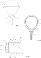
- Padel's racket is composed of a head 1 or sieve constituting the strike zone of the ball, a handle 2 intended to be taken in hand by the player and a heart 3 which connects the head 1 to the neck 2.
- This core zone 3 has a recess 4. It could be envisaged that this zone 3 has several recesses and for example three recesses 4a, 4b, 4c as illustrated in FIGS. figures 2 and 5 , or even no recess: the zone of the heart 3 would be in this case then completely full.
- the head of a padel racket has unrepresented through holes, to avoid resistance to friction in the air and make the racket more manoeuvrable.
- a first embodiment of the invention is illustrated in Figures 2 to 4 .
- the structure of the head 1 of the racket is constituted by a central core 5 covered on its two lower planar surfaces 5b and 5a upper respectively by two layers of composite materials 9b and 9a. Are these layers even covered respectively by two protective layers 10b and 10a forming the striking surfaces.
- the lower faces 5b and 5a of the core 5 are located in planes parallel to the strike planes of the racket.
- the protective layers 10a and 10b may consist either of layers of plastic material, transparent or not, positioned in the mold before molding or reported after molding of the racket by gluing, or by additional layers of paint or varnish applied after molding the racket, directly on the composite layers 9a and 9b.
- These layers are generally of a thin thickness of the order of a millimeter and even less than 1 mm.
- These protective layers and these layers of composite materials extend, in the illustrated embodiment, in the area of the heart 3 of the racket and also on the handle 2 of the racket.
- the layers of composite materials 9a, 9b may consist of one or more elements, juxtaposed and / or superimposed.
- the composite materials used may be based on glass fibers, carbon fibers, aramid fibers or natural fibers, used alone or in combination.
- the fibers may be unidirectional, but in an advantageous embodiment, the fibers are crossed and oriented, generally at 0 and 90 degrees to the longitudinal axis of the handle 2. These fibers are impregnated with resin, such as epoxy resin. During molding, the resin ensures the bonding of all the components of the racket between them.
- the core 5 of the racket is composed of a layer of generally thermoplastic polymeric foam, such as, for example, an Ethylene Vinyl Acetal or EVA foam. These foams are of low density, and low hardness, preferably between 10 and 30 Shore A. Such foam is flexible and deformable and therefore has a low rigidity, the Young's modulus of such a foam is for example lower at 500 MPa.
- This core of substantially oval shape in a plane parallel to the striking surfaces, gives the racket a sandwich structure by separating the layers of composite materials 9a and 9b from the thickness of the core 5.
- the thickness of this core 5 is in large general, between 10 and 50mm, preferably between 35 and 40mm. It will not depart from the scope of the invention if the core consists of several parts nested in each other and / or if the core itself consists of several superimposed layers.
- the periphery of the core 5 is constituted by the peripheral surface 5c of the core 5.
- This peripheral surface 5c of the core 5 is covered with several elements explained below which form and reinforce the periphery of the racket.
- peripheral surface 5c of the core is covered at least partially by a reinforcing strip 8 or additional reinforcement element 8, then by a tubular element 6 which covers the outer face of this reinforcing strip 8.
- This tubular element 6 forms the around the head of the racket and also extends at the handle 2 by two rectilinear portions 6e and 6d.
- the additional reinforcing element 8 is made of a material that is much more rigid than the foam constituting the core 5, such as for example aluminum, a composite based on fiberglass or carbon fibers, or even a rigid plastic material of ABS type preferably loaded with fiberglass, more rigid than the EVA.
- the Young's modulus of the material of the additional reinforcement element will for example be greater than 3000 MPa, preferably greater than 8000 MPa and even greater than 10000 MPa. Indeed, the greater the stiffness of the additional reinforcing element 8, the greater the section of the tube 6 and in particular the inner surface 6b of the tube 6 will be regular and well formed.
- the thickness of this additional reinforcing element 8 is thin, of the order of a millimeter, for example between 0.2 and 1.5 mm to not increase too much the weight of the racket.
- This additional reinforcement element 8 is positioned at least on the front part of the racket head 1 and preferably also extends on the lateral sides of the racket to the level of the heart 3 of the racket as illustrated in FIG. figure 3 .
- this additional reinforcing element 8 can completely circle the core 5.
- this additional reinforcing element 8 is a strip directly in contact with the core.
- This additional reinforcing element 8 is positioned between the peripheral surface 5c of the core 5 and the inner wall 6b of the tubular element 6.
- the tubular element 6 or tube 6 consists of a braid made of composite materials based on oriented fibers. glass and / or carbon and / or optionally resin impregnated aramid in which is inserted an inflatable sheath which, during the molding of the racket takes the form of a tube under the effect of inflation of this sheath.
- this tube 6 is hollow and its section has an arcuate zone 6a which matches the shape of the racket mold on its outward face facing the outside of the racket and a substantially rectilinear zone 6b on its inner face facing towards the center of the sieve of the racket which marries the outer shape of the peripheral surface 5c of the core 5.
- This substantially rectilinear area of the tube 6 is obtained by the fact that the tube 6 bears on the strip 8 which is rigid enough not to undergo deformations when pressure is exerted by the walls of the tube 6 during its inflation during molding.
- This reinforcing strip 8 thus makes it possible to obtain a tube 6 which has an internal wall or internal wall 6b that is regular, without undulation and without wrinkles.
- the invention therefore proposes positioning at least one additional reinforcement element 8 between the peripheral surface 5c of the core 5 and the tubular element 6.
- the tube 6 bears against the rigid wall of the mold to form its outer wall or 6a outer, and against the additional reinforcing element 8 to form its inner or inner wall 6b.
- the additional reinforcing element 8 is a band which preferably has a width corresponding substantially to the thickness of the core. The sides of this band then become contiguous with the lower and upper reinforcements 9a and 9b located in planes parallel to the striking planes.
- the peripheral reinforcement 8 could be formed by an extension of one or both of the lower and upper reinforcements which would be curved to fit around the periphery of the core.
- the reinforcing strip 8 could be of slightly smaller thickness or greater in order to provide a bearing surface sufficient to form the inner face 6b of the tube 6. In the case where the width of this band is greater at the width of the core, a part of this band could cover more or less partially, the lower surface or surfaces 5b and 5a of the core 5.
- This strip 8 preferably has upper and lower edges, 8i and 8s parallel and rectilinear but edges chiseled by notches of shallow depths could also be suitable.
- the tubular element 6 has two ends 6d and 6e forming a portion of the handle.
- the inner portion of the handle is completed by a second tubular element 7 or additional tube 7 which is part of the heart of the racket to stiffen this part of the racket.
- This additional tube 7 comes in its upper part in contact with the lower part of the core.
- the additional reinforcing element 8 is extended at the lower part of the core to allow the additional tube 7 to come to bear against the additional reinforcing element 8 during its inflation. and during the molding to obtain a hollow tube 7 formed correctly in the heart area, without having deformed the core 5 of the racket during molding.
- the figures 5 and 6 show a second embodiment in which it is envisaged to superpose on the additional reinforcement element 8 a second additional reinforcement element 8a for the main purpose of increasing the rigidity of the interface constituted here by the two elements 8 and 8a and positioned between the periphery of the core 5 and the inner face 6b of the tube 6.
- This second additional reinforcing element 8a may be a strip of a length similar to the length of the strip formed by the element 8 or may be of shorter length and positioned superimposed on the element 8 in a particular zone where the forming tube 6 is more delicate.
- the figure 7 is an alternative embodiment which has a band 8b consisting of an elastomeric element for damping the racket during the beating strikes.
- This band 8b is superimposed on the additional reinforcing element 8 and comes into contact with the inner face 6b of the tube 6.
- This elastomeric element 8b may have a length similar to the band 8 or possibly less.
- the tubular element 6 does not rely directly on the additional reinforcing element 8 in certain zones, but this does not affect the good formation of the section of the tube 6 since the tubular element 6 is still a rigid support on the side of the core 5, still avoiding the core 5 to be deformed during molding.
- the figure 8 is another embodiment where one of the two additional reinforcing elements 8 and 8c may have recesses 8d for lightening this additional reinforcing element.
- the number of recesses 8d and the size of the recesses 8d will be chosen such that these recesses do not affect the forming of the inner wall 6b of the tube 6. These recesses can be non-emerging or on the contrary completely through.
- the shape of the recesses or holes may be various, round or oval or polygonal. The distribution of these recesses on the band can be a particular reason, distributed regularly or not.
- the molding of the racket is carried out by applying known pressure and temperature parameters combined with an inflation operation of the sheaths inserted inside the composite braids 6 and 7 to obtain the hollow tubes 6 and 7.
- this molding and inflating operation the inner wall of the hollow tube 6 rests against the additional reinforcing element 8 which, because of its sufficient rigidity, does not crush or deform, which allows the hollow tube to be formed properly, without presenting areas of low breaking strength.
- the additional reinforcing element 8 surrounding the periphery of the core 5 may be arranged around the core 5 during molding, with or without adhesive means, or it may be positioned around the core before molding, by gluing or by injection on the periphery of the core 5 in the area around the core 5 concerned.
- the invention has the advantage of solving manufacturing problems and in particular of solving the problems encountered in correctly forming the peripheral tube and in particular its inner wall which is the closest to the core, which is an essential constituent element of the structure of the tube.
- a padel racket a racket.
- the invention presents a simple, economical solution without adding excessive weight.
Abstract
Raquette comportant d'une part un noyau (5) recouvert sur chacune de ses faces parallèles aux surfaces de frappe de la raquette par au moins une couche de renfort (9a, 9b) et d'autre part un élément tubulaire (6) formant le pourtour de la raquette caractérisée en ce qu'au moins un élément supplémentaire de renfort (8) est positionné entre la surface périphérique du noyau (5) et l'élément tubulaire (6).Racket comprising on the one hand a core (5) covered on each of its faces parallel to the striking surfaces of the racket by at least one reinforcing layer (9a, 9b) and on the other hand a tubular element (6) forming the around the racket characterized in that at least one additional reinforcing element (8) is positioned between the peripheral surface of the core (5) and the tubular element (6).
Description
L'invention concerne une raquette, permettant de frapper une balle, et ne présentant pas de cordage. En particulier elle est destinée au jeu de Padel.The invention relates to a racket, for hitting a ball, and not having a rope. In particular it is intended for Padel's game.
Le Padel est un jeu de balle qui se joue avec une raquette sans cordes, dont la zone de frappe est pleine ou quasiment pleine étant donné qu'elle peut comporter des trous traversant transversalement la tête de la raquette. Le jeu de Padel se joue sur un terrain séparé par un filet et entouré de murs, la balle devant rebondir au sol et pouvant également rebondir sur les murs.Padel is a ball game that is played with a racket without ropes, whose striking zone is full or almost full as it may have holes crossing transversely the head of the racket. Padel's game is played on a field separated by a net and surrounded by walls, with the ball bouncing off the ground and bouncing off the walls.
La raquette de Padel est constituée de trois parties, qui sont la tête, le coeur et le manche. La tête correspond à la zone de frappe de la balle, le manche correspond à la partie qui est serrée par la main du joueur et le coeur est la zone qui relie la tête au manche de la raquette.Padel's racket consists of three parts, which are the head, the heart and the neck. The head corresponds to the strike zone of the ball, the neck is the part that is tightened by the player's hand and the heart is the area that connects the head to the handle of the racket.
De façon générale, les raquettes de Padel comprennent dans la zone de frappe ou tête de la raquette, un noyau recouvert sur chacune de ses deux faces de frappe par un renfort généralement en matériau composite. Par ailleurs, un tube généralement creux entoure la tête de la raquette et les deux extrémités de ce tube se rejoignent au niveau du manche, comme décrit dans le document
Aussi, pour remédier à ces inconvénients, le but de l'invention est de proposer une structure interne de raquette particulière permettant d'obtenir un tube ou élément tubulaire bien formé. Un autre but de l'invention permet d'augmenter la résistance de la raquette.Also, to overcome these disadvantages, the object of the invention is to provide a particular internal racquet structure for obtaining a tube or tubular element well formed. Another object of the invention makes it possible to increase the resistance of the racket.
Plus précisément, l'invention porte sur une raquette qui comporte d'une part, un noyau recouvert sur chacune de ses faces parallèles aux surfaces de frappe de la raquette par au moins une couche de renfort et d'autre part, un élément tubulaire formant le pourtour de la raquette.More specifically, the invention relates to a racket which comprises firstly, a core covered on each of its faces parallel to the striking surfaces of the racket by at least one reinforcing layer and secondly, a tubular element forming around the racket.
Conformément à l'invention, cette raquette se caractérise en ce qu'au moins un élément supplémentaire de renfort est positionné entre la surface périphérique du noyau et l'élément tubulaire.According to the invention, this racket is characterized in that at least one additional reinforcing element is positioned between the peripheral surface of the core and the tubular element.
Autrement dit, la surface périphérique du noyau ou le pourtour du noyau qui est destiné à donner à la raquette son épaisseur, est recouverte directement ou indirectement, partiellement ou totalement, par une couche de renfort supplémentaire, nommée élément de renfort supplémentaire, sur lequel vient s'appuyer par sa surface interne un élément tubulaire qui forme le pourtour de la tête de raquette et qui peut également se prolonger jusqu'au manche de la raquette.In other words, the peripheral surface of the core or the periphery of the core which is intended to give the racket its thickness, is covered directly or indirectly, partially or totally, by an additional reinforcing layer, called additional reinforcing element, on which comes to rely on its inner surface a tubular element which forms the periphery of the racket head and which can also extend to the handle of the racket.
En d'autres termes, on interpose entre la paroi interne de l'élément tubulaire et le noyau, un élément de renfort supplémentaire qui prévient l'enfoncement du noyau lors de l'expansion de l'élément tubulaire.In other words, there is interposed between the inner wall of the tubular member and the core, an additional reinforcing member which prevents the depression of the core during expansion of the tubular member.
Selon des aspects avantageux mais non obligatoires de l'invention, la raquette selon l'invention peut incorporer une ou plusieurs des caractéristiques suivantes.According to advantageous but not compulsory aspects of the invention, the racket according to the invention can incorporate one or more of the following characteristics.
L'élément supplémentaire de renfort est de préférence plus rigide que le matériau du noyau.The additional reinforcing element is preferably more rigid than the core material.
L'élément supplémentaire de renfort peut être constitué par une bande en contact avec la surface périphérique du noyau ou pourtour du noyau.The additional reinforcing element may consist of a strip in contact with the peripheral surface of the core or around the core.
Cette bande peut comporter des bords parallèles et peut présenter une largeur correspondant sensiblement à l'épaisseur du noyau.This band may have parallel edges and may have a width substantially corresponding to the thickness of the core.
L'élément supplémentaire de renfort peut ne recouvrir que partiellement la surface périphérique du noyau. Autrement dit, la longueur de la bande formant l'élément supplémentaire de renfort est inférieure au périmètre du noyau.The additional reinforcing member may only partially cover the peripheral surface of the core. In other words, the length of the band forming the additional reinforcement element is less than the perimeter of the core.
Par ailleurs, l'élément supplémentaire de renfort peut recouvrir totalement la surface périphérique du noyau.Moreover, the additional reinforcing element can completely cover the peripheral surface of the core.
La raquette peut également comporter un deuxième élément tubulaire au niveau de son coeur qui s'appuie sur une partie de l'élément supplémentaire de renfort.The racket may also include a second tubular element at its core which rests on a portion of the additional reinforcing element.
La raquette peut présenter deux éléments supplémentaires de renfort superposés ou même un plus grand nombre si besoin.The racket may have two additional reinforcing elements superimposed or even a larger number if necessary.
Un élément élastomère peut être superposé sur l'élément supplémentaire de renfort ou sur l'un des éléments supplémentaires de renfort.An elastomeric element may be superimposed on the additional reinforcing element or on one of the additional reinforcing elements.
L'élément supplémentaire peut aussi comporter des évidements. En particulier ces évidements peuvent être des petits trous traversant de formes diverses et de petites dimensions, de l'ordre de quelques millimètres.The additional element may also include recesses. In particular these recesses can be small through holes of various shapes and small dimensions, of the order of a few millimeters.
La raquette selon l'invention peut présenter un noyau formé de plusieurs couches superposées et/ ou peut présenter un noyau formé de plusieurs parties emboitées les unes avec les autres.The racket according to the invention may have a core formed of several superimposed layers and / or may have a core formed of several parts nested with each other.
La raquette selon l'invention peut présenter également une structure où les couches de renfort et l'élément tubulaire sont recouverts par une couche de protection.The racket according to the invention may also have a structure where the reinforcing layers and the tubular element are covered by a protective layer.
La Raquette selon l'invention présente généralement un élément tubulaire qui est un tube creux.The racket according to the invention generally has a tubular element which is a hollow tube.
Lors de la fabrication de la raquette selon l'invention, la raquette comprenant d'une part, un noyau recouvert sur chacune de ses faces formant surfaces de frappe par au moins une couche de renfort et d'autre part, un élément tubulaire formant le pourtour de la raquette, on positionne dans le moule de la raquette un élément supplémentaire de renfort sur la surface périphérique du noyau, le noyau ayant été préalablement positionné dans le moule. Puis, autour de cet élément supplémentaire de renfort, on positionne une tresse composite dans laquelle est insérée une gaine gonflable, telle que lors de l'opération de gonflage et de moulage, la tresse composite forme un tube creux dont la paroi intérieure s'appuie directement ou indirectement contre l'élément supplémentaire de renfort pour former correctement l'élément tubulaire.During the manufacture of the racket according to the invention, the racket comprising, on the one hand, a core covered on each of its faces forming striking surfaces by at least one reinforcing layer and, on the other hand, a tubular element forming the around the racket, is placed in the racket mold an additional reinforcing element on the peripheral surface of the core, the core having been previously positioned in the mold. Then, around this additional reinforcing element, is positioned a composite braid in which is inserted an inflatable sheath, such that during the inflation and molding operation, the composite braid forms a hollow tube whose inner wall is supported directly or indirectly against the additional reinforcing element to properly form the tubular element.
Lors de la fabrication de la raquette, l'élément supplémentaire de renfort est découpé en forme de bande. Cette découpe en bande peut être réalisée soit préalablement au moulage, soit pendant la phase de mise en moule des différents éléments constitutifs de la raquette.During the manufacture of the racket, the additional reinforcing element is cut into a band shape. This cutting strip can be performed either prior to molding, or during the setting phase of the various components of the racket.
L'invention va être décrite ci-après, en référence aux dessins annexés, donnés uniquement à titre d'exemple, non limitatifs, dans lesquels :
- La
figure 1 est une vue de dessus de la raquette selon l'invention. - La
figure 2 est une vue en perspective, en éclatée, des différents éléments constitutifs de la raquette selon un premier mode de réalisation de l'invention. - La
figure 3 est une vue en une coupe incomplète réalisée dans le plan de symétrie principal de la raquette selon le premier mode de réalisation de l'invention, les éléments de renfort inférieur et supérieur ainsi que les couches de protection inférieure et supérieure n'étant pas représentés. - La
figure 4 est une section partielle selon A-A de la raquette selon le premier mode de réalisation de l'invention. - La
figure 5 est une vue en perspective en éclatée des différents éléments constitutifs de la raquette selon un deuxième mode de réalisation de l'invention. - La
figure 6 est une section partielle selon A-A de la raquette selon le deuxième mode de réalisation de l'invention. - La
figure 7 est une vue en perspective de deux éléments internes à la raquette selon une variante de réalisation. - La
figure 8 est une vue en perspective de deux éléments internes à la raquette selon une autre variante de réalisation.
- The
figure 1 is a top view of the racket according to the invention. - The
figure 2 is a perspective view, exploded, of the various components of the racket according to a first embodiment of the invention. - The
figure 3 is a view in an incomplete section made in the main plane of symmetry of the racket according to the first embodiment of the invention, the lower and upper reinforcement elements as well as the lower and upper protection layers not being shown. - The
figure 4 is a partial section AA of the racket according to the first embodiment of the invention. - The
figure 5 is an exploded perspective view of the various components of the racket according to a second embodiment of the invention. - The
figure 6 is a partial section AA of the racket according to the second embodiment of the invention. - The
figure 7 is a perspective view of two elements internal to the racket according to an alternative embodiment. - The
figure 8 is a perspective view of two elements internal racket according to another embodiment.
Comme illustré à la
Un premier mode de réalisation de l'invention est illustré aux
Les couches de matériaux composites 9a, 9b peuvent être constituées d'un seul ou plusieurs éléments, juxtaposés et / ou superposés. Les matériaux composites utilisés peuvent être à base de fibres de verre, fibres de Carbone, fibres d'Aramide ou encore fibres naturelles, utilisées seules ou en combinaison. Les fibres peuvent être unidirectionnelles, mais dans une réalisation avantageuse, les fibres sont croisées et orientées, généralement à 0 et 90 degrés par rapport à l'axe longitudinal du manche 2. Ces fibres sont imprégnées de résine, comme par exemple de résine époxy. Lors du moulage, la résine assure le collage de tous les éléments constitutifs de la raquette entre eux.The layers of
Le noyau 5 de la raquette est composé d'une couche de mousse polymérique généralement thermoplastique, comme par exemple une mousse d'Ethylène Vinyle d'Acétal ou EVA. Ces mousses sont de faible densité, et de faible dureté, de préférence comprise entre 10 et 30 Shore A. Une telle mousse est souple et déformable et présente donc une faible rigidité, le module d'Young d'une telle mousse étant par exemple inférieur à 500 MPa. Ce noyau, de forme sensiblement ovale dans un plan parallèle aux surfaces de frappe, confère à la raquette une structure sandwich en écartant les couches de matériaux composites 9a et 9b de l'épaisseur du noyau 5. L'épaisseur de ce noyau 5 est en général grande, comprise entre 10 et 50mm, de préférence entre 35 et 40mm. On ne sortira pas du cadre de l'invention si le noyau est constitué de plusieurs parties emboitées les unes dans les autres et/ou si ce noyau est constitué lui-même de plusieurs couches superposées.The
Le pourtour du noyau 5 est constitué par la surface périphérique 5c du noyau 5. Cette surface périphérique 5c du noyau 5 est recouverte de plusieurs éléments explicités ci-dessous qui forment et renforcent le pourtour de la raquette.The periphery of the
En effet la surface périphérique 5c du noyau est recouverte au moins partiellement par une bande de renfort 8 ou élément supplémentaire de renfort 8, puis par un élément tubulaire 6 qui recouvre la face extérieure de cette bande de renfort 8. Cet élément tubulaire 6 forme le pourtour de la tête de la raquette et se prolonge également au niveau du manche 2 par deux portions rectilignes 6e et 6d.Indeed the
L'élément supplémentaire de renfort 8 est constitué d'un matériau beaucoup plus rigide que la mousse constitutive du noyau 5, comme par exemple d'Aluminium, d'un composite à base de fibre de verre ou de fibres de Carbone ou encore d'un matériau plastique rigide de type ABS de préférence chargé en fibre de verre, plus rigide que l'EVA. Le module d'Young du matériau de l'élément supplémentaire de renfort sera par exemple supérieur à 3000 MPa, de préférence supérieur à 8000 MPa et même encore supérieur à 10000 MPa. En effet, plus la rigidité de l'élément supplémentaire de renfort 8 est grande, plus la section du tube 6 et en particulier la surface intérieure 6b du tube 6 sera régulière et bien formée. L'épaisseur de cet élément supplémentaire de renfort 8 est fine, de l'ordre du millimètre, par exemple compris entre 0.2 et 1.5mm pour ne pas augmenter de façon trop importante le poids de la raquette.The additional reinforcing
Cet élément supplémentaire de renfort 8 est positionné au moins sur la partie avant de la tête 1 de raquette et se prolonge de préférence également sur les côtés latéraux de la raquette jusqu'au niveau du coeur 3 de la raquette comme illustré à la
Cet élément supplémentaire de renfort 8 est positionné entre la surface périphérique 5c du noyau 5 et la paroi intérieure 6b de l'élément tubulaire 6. L'élément tubulaire 6 ou tube 6 est constitué d'une tresse en matériaux composites à base de fibres orientées de verre et/ou de Carbone et/ou éventuellement d'Aramide imprégnée de résine dans laquelle est insérée une gaine gonflable qui, lors du moulage de la raquette prend la forme d'un tube sous l'effet du gonflage de cette gaine. Comme illustré à la
De ce fait, lors de la phase de gonflage pendant le moulage de la raquette, le tube 6 s'appuie contre la paroi rigide du moule pour former sa paroi externe ou extérieure 6a, et contre l'élément supplémentaire 8 de renfort pour former sa paroi interne ou intérieure 6b.Therefore, during the inflation phase during the molding of the racket, the
Comme illustré à la
Dans une autre variante également, la bande de renfort 8 pourrait être d'épaisseur légèrement inférieure ou supérieure afin de fournir une surface d'appui suffisante pour former la face interne 6b du tube 6. Dans le cas où la largeur de cette bande est supérieure à la largeur du noyau, une partie de cette bande pourrait recouvrir plus ou moins partiellement, la ou les surfaces inférieures 5b et supérieures 5a du noyau 5.In another variant also, the reinforcing
Cette bande 8 présente de préférence des bords inférieurs et supérieurs, 8i et 8s parallèles et rectilignes mais des bords ciselés par des crans de faibles profondeurs pourraient également convenir.This
Comme déjà indiqué précédemment, l'élément tubulaire 6 présente deux extrémités 6d et 6e qui forment une partie du manche. La partie intérieure du manche est complétée par un deuxième élément tubulaire 7 ou tube supplémentaire 7 qui constitue une partie du coeur de la raquette pour rigidifier cette partie de la raquette. On ne sortira toutefois pas du cadre de l'invention si la raquette ne présente pas ce tube supplémentaire 7. Ce tube supplémentaire 7 vient dans sa partie supérieure au contact de la partie inférieure du noyau. Aussi, dans une réalisation avantageuse, il est intéressant que l'élément supplémentaire de renfort 8 se prolonge au niveau de la partie inférieure du noyau pour permettre au tube supplémentaire 7 de venir s'appuyer contre l'élément supplémentaire de renfort 8 pendant son gonflage et pendant le moulage pour obtenir un tube creux 7 formé correctement dans la zone du coeur, sans avoir déformé le noyau 5 de la raquette pendant le moulage.As already indicated above, the
Les
La
La
En ce qui concerne le procédé de fabrication de la raquette, il est le suivant.
Dans le fond du moule sont positionnés successivement
- la couche inférieure de
protection 10b, - la ou les couches de renfort inférieures 9b,
le noyau 5.
- la ou les éléments supplémentaires de renfort 8,
- la tresse
composite 6 dans laquelle est insérée une gaine gonflable, - la tresse
composite 7 dans laquelle est également insérée une gaine gonflable.
- la ou les couches supérieures de renfort 9a,
- la couche supérieure de
protection 10a.
In the bottom of the mold are positioned successively
- the
lower protection layer 10b, - the at least one reinforcing
layer 9b, - the
core 5.
- the additional reinforcing element or
elements 8, - the
composite braid 6 in which is inserted an inflatable sheath, - the
composite braid 7 in which is also inserted an inflatable sheath.
- the upper layer or layers of
reinforcement 9a, - the upper
protective layer 10a.
Après fermeture du moule, le moulage de la raquette est effectué par application de paramètres de pression et température connus combinée à une opération de gonflage des gaines insérées à l'intérieur des tresses composites 6 et 7 pour obtenir les tubes creux 6 et 7. Pendant cette opération de moulage et de gonflage, la paroi intérieure du tube creux 6 s'appuie contre l'élément supplémentaire de renfort 8 qui, du fait de sa rigidité suffisante, ne s'écrase pas et ne se déforme pas, ce qui permet au tube creux d'être formé correctement, sans présenter de zones de faible résistance à la rupture.After closing the mold, the molding of the racket is carried out by applying known pressure and temperature parameters combined with an inflation operation of the sheaths inserted inside the
On ne sortira pas du cadre de l'invention si la raquette ne présente pas de tresse composite 7 formant le tube 7. Sans cet élément, le procédé de fabrication est alors légèrement simplifié puisque la mise en moule présente un élément de moins.It will not be departing from the scope of the invention if the racket does not have a
L'élément supplémentaire de renfort 8 entourant le pourtour du noyau 5 peut être disposé autour du noyau 5 lors de la mise en moule, avec ou sans moyen de collage ou encore il peut être positionné autour du noyau avant le moulage, par collage ou par sur injection sur le pourtour du noyau 5 dans la zone du pourtour du noyau 5 concerné.The additional reinforcing
L'invention présente l'avantage de résoudre des problèmes de fabrication et en particulier de résoudre les problèmes rencontrés pour former correctement le tube périphérique et en particulier sa paroi intérieure la plus proche du noyau, qui est un élément constitutif essentiel de la structure d'une raquette de Padel. L'invention présente une solution simple, économique et sans ajout de poids excessif. De plus, selon les dimensions, selon les matériaux utilisés pour le renfort supplémentaire ainsi que selon le nombre de renforts supplémentaires, il est possible d'intervenir sur le comportement de la raquette lors de la frappe de la balle, ainsi que sur la résistance de cette raquette.The invention has the advantage of solving manufacturing problems and in particular of solving the problems encountered in correctly forming the peripheral tube and in particular its inner wall which is the closest to the core, which is an essential constituent element of the structure of the tube. a padel racket. The invention presents a simple, economical solution without adding excessive weight. In addition, according to the dimensions, according to the materials used for the additional reinforcement and the number of additional reinforcements, it is possible to intervene on the behavior of the racket during the striking of the ball, as well as on the resistance of the ball. this racket.
Claims (16)
Applications Claiming Priority (1)
| Application Number | Priority Date | Filing Date | Title |
|---|---|---|---|
| FR1652703A FR3049469B1 (en) | 2016-03-29 | 2016-03-29 | RACKET, ESPECIALLY PADEL RACKET STRUCTURE |
Publications (2)
| Publication Number | Publication Date |
|---|---|
| EP3225288A1 true EP3225288A1 (en) | 2017-10-04 |
| EP3225288B1 EP3225288B1 (en) | 2019-05-08 |
Family
ID=56555477
Family Applications (1)
| Application Number | Title | Priority Date | Filing Date |
|---|---|---|---|
| EP17156152.5A Active EP3225288B1 (en) | 2016-03-29 | 2017-02-14 | Racquet, in particular padel racquet structure |
Country Status (3)
| Country | Link |
|---|---|
| EP (1) | EP3225288B1 (en) |
| ES (1) | ES2729338T3 (en) |
| FR (1) | FR3049469B1 (en) |
Cited By (4)
| Publication number | Priority date | Publication date | Assignee | Title |
|---|---|---|---|---|
| FR3064186A1 (en) * | 2017-03-22 | 2018-09-28 | Babolat Vs | RACKET OF PADEL |
| FR3119779A1 (en) * | 2021-02-18 | 2022-08-19 | Tecnifibre | Racquet frame, racquet comprising such a frame and method of manufacturing such a frame or such a racquet. |
| EP4154950A1 (en) * | 2021-09-23 | 2023-03-29 | Head Technology GmbH | Racquet for a ball game and method for producing the same |
| WO2023172209A1 (en) | 2022-03-09 | 2023-09-14 | Casa De Padel J.S.A. | Padel racquet with an improved hitting area |
Citations (5)
| Publication number | Priority date | Publication date | Assignee | Title |
|---|---|---|---|---|
| US4130277A (en) * | 1977-07-01 | 1978-12-19 | Marcraft Recreation Corp. | Composite paddle rim |
| ES1064837U (en) * | 2007-02-16 | 2007-05-01 | Rodision Sport, S.L. | Blade paddle (Machine-translation by Google Translate, not legally binding) |
| WO2009068759A1 (en) * | 2007-11-28 | 2009-06-04 | Decathlon | Ball game device, especially a racket, and method of manufacture |
| ES2395181A1 (en) | 2011-08-11 | 2013-02-08 | Pedro Dominguez Escudero | Procedure for manufacturing padel blades and obtained product (Machine-translation by Google Translate, not legally binding) |
| ES2544004A2 (en) * | 2014-02-17 | 2015-08-26 | World Champion Brands, S.L. | Blade paddle (Machine-translation by Google Translate, not legally binding) |
-
2016
- 2016-03-29 FR FR1652703A patent/FR3049469B1/en active Active
-
2017
- 2017-02-14 EP EP17156152.5A patent/EP3225288B1/en active Active
- 2017-02-14 ES ES17156152T patent/ES2729338T3/en active Active
Patent Citations (5)
| Publication number | Priority date | Publication date | Assignee | Title |
|---|---|---|---|---|
| US4130277A (en) * | 1977-07-01 | 1978-12-19 | Marcraft Recreation Corp. | Composite paddle rim |
| ES1064837U (en) * | 2007-02-16 | 2007-05-01 | Rodision Sport, S.L. | Blade paddle (Machine-translation by Google Translate, not legally binding) |
| WO2009068759A1 (en) * | 2007-11-28 | 2009-06-04 | Decathlon | Ball game device, especially a racket, and method of manufacture |
| ES2395181A1 (en) | 2011-08-11 | 2013-02-08 | Pedro Dominguez Escudero | Procedure for manufacturing padel blades and obtained product (Machine-translation by Google Translate, not legally binding) |
| ES2544004A2 (en) * | 2014-02-17 | 2015-08-26 | World Champion Brands, S.L. | Blade paddle (Machine-translation by Google Translate, not legally binding) |
Cited By (5)
| Publication number | Priority date | Publication date | Assignee | Title |
|---|---|---|---|---|
| FR3064186A1 (en) * | 2017-03-22 | 2018-09-28 | Babolat Vs | RACKET OF PADEL |
| FR3119779A1 (en) * | 2021-02-18 | 2022-08-19 | Tecnifibre | Racquet frame, racquet comprising such a frame and method of manufacturing such a frame or such a racquet. |
| EP4046695A1 (en) * | 2021-02-18 | 2022-08-24 | Tecnifibre | Frame for racquet, racquet comprising such a frame and method for manufacturing such a frame or such a racquet |
| EP4154950A1 (en) * | 2021-09-23 | 2023-03-29 | Head Technology GmbH | Racquet for a ball game and method for producing the same |
| WO2023172209A1 (en) | 2022-03-09 | 2023-09-14 | Casa De Padel J.S.A. | Padel racquet with an improved hitting area |
Also Published As
| Publication number | Publication date |
|---|---|
| ES2729338T3 (en) | 2019-10-31 |
| EP3225288B1 (en) | 2019-05-08 |
| FR3049469A1 (en) | 2017-10-06 |
| FR3049469B1 (en) | 2018-04-06 |
Similar Documents
| Publication | Publication Date | Title |
|---|---|---|
| EP3225288B1 (en) | Racquet, in particular padel racquet structure | |
| EP1475303B1 (en) | Surfboard and method for its production | |
| EP2000180B1 (en) | Snowboard or skateboard with reinforcement made of natural fibers | |
| WO2005082187A1 (en) | Semi-rigid protective helmet | |
| EP3305378B1 (en) | Racquet, in particular structure of padel racquet | |
| EP2099536A1 (en) | Racket handle insert and corresponding handle and racket | |
| EP1731416A1 (en) | Surf-board with a sandwich deck having an elastic core | |
| FR3038844A1 (en) | RACKET, ESPECIALLY PADEL RACKET WITH DECORATION | |
| WO2000025870A1 (en) | Racket string pattern guide, frame side groove | |
| EP0665034B1 (en) | Ski with an "in situ" injected core | |
| EP1683552A1 (en) | Table tennis racket | |
| WO2010094894A1 (en) | Tennis racket with shock absorbing means | |
| FR3058899A1 (en) | SLIDING BOARD STRUCTURE ELEMENT | |
| FR3042124A1 (en) | RACKET, ESPECIALLY PADEL RACKET STRUCTURE | |
| EP1321357A1 (en) | Hollow gliding board with inertia weights | |
| EP0081834B1 (en) | Light weight ski with core and process for making it | |
| EP2758137B1 (en) | Handle grip for badminton racquet and associated method of manufacture | |
| FR3056919A1 (en) | RACKET, ESPECIALLY PADEL RACKET STRUCTURE | |
| EP1908501A1 (en) | Snowboard or skateboard comprising a special tip | |
| EP2353672B1 (en) | Glideboard for snow with sidewalls of variable width | |
| EP2602008B1 (en) | Board for snow gliding | |
| FR2878817A1 (en) | Board float e.g. surf float, for gliding on water, has core covered by outer cover and including spacers made of plastic foam material, connecting deck and bottom and being compressible elastically along deck to bottom vertical direction | |
| CA1096416A (en) | Pas de traduction disponible | |
| FR2818915A1 (en) | Ski or snowboard has cut out portions in reinforcing layer corresponding to relief zones in upper protective surface | |
| FR3067615B1 (en) | BOARD OF SLIDERS |
Legal Events
| Date | Code | Title | Description |
|---|---|---|---|
| PUAI | Public reference made under article 153(3) epc to a published international application that has entered the european phase |
Free format text: ORIGINAL CODE: 0009012 |
|
| STAA | Information on the status of an ep patent application or granted ep patent |
Free format text: STATUS: THE APPLICATION HAS BEEN PUBLISHED |
|
| AK | Designated contracting states |
Kind code of ref document: A1 Designated state(s): AL AT BE BG CH CY CZ DE DK EE ES FI FR GB GR HR HU IE IS IT LI LT LU LV MC MK MT NL NO PL PT RO RS SE SI SK SM TR |
|
| AX | Request for extension of the european patent |
Extension state: BA ME |
|
| STAA | Information on the status of an ep patent application or granted ep patent |
Free format text: STATUS: REQUEST FOR EXAMINATION WAS MADE |
|
| 17P | Request for examination filed |
Effective date: 20180321 |
|
| RBV | Designated contracting states (corrected) |
Designated state(s): AL AT BE BG CH CY CZ DE DK EE ES FI FR GB GR HR HU IE IS IT LI LT LU LV MC MK MT NL NO PL PT RO RS SE SI SK SM TR |
|
| GRAP | Despatch of communication of intention to grant a patent |
Free format text: ORIGINAL CODE: EPIDOSNIGR1 |
|
| STAA | Information on the status of an ep patent application or granted ep patent |
Free format text: STATUS: GRANT OF PATENT IS INTENDED |
|
| RIC1 | Information provided on ipc code assigned before grant |
Ipc: A63B 102/08 20150101ALN20181011BHEP Ipc: A63B 59/42 20150101AFI20181011BHEP |
|
| INTG | Intention to grant announced |
Effective date: 20181031 |
|
| GRAS | Grant fee paid |
Free format text: ORIGINAL CODE: EPIDOSNIGR3 |
|
| GRAA | (expected) grant |
Free format text: ORIGINAL CODE: 0009210 |
|
| STAA | Information on the status of an ep patent application or granted ep patent |
Free format text: STATUS: THE PATENT HAS BEEN GRANTED |
|
| AK | Designated contracting states |
Kind code of ref document: B1 Designated state(s): AL AT BE BG CH CY CZ DE DK EE ES FI FR GB GR HR HU IE IS IT LI LT LU LV MC MK MT NL NO PL PT RO RS SE SI SK SM TR |
|
| REG | Reference to a national code |
Ref country code: GB Ref legal event code: FG4D Free format text: NOT ENGLISH |
|
| REG | Reference to a national code |
Ref country code: CH Ref legal event code: EP Ref country code: AT Ref legal event code: REF Ref document number: 1129266 Country of ref document: AT Kind code of ref document: T Effective date: 20190515 |
|
| REG | Reference to a national code |
Ref country code: DE Ref legal event code: R096 Ref document number: 602017003707 Country of ref document: DE |
|
| REG | Reference to a national code |
Ref country code: IE Ref legal event code: FG4D Free format text: LANGUAGE OF EP DOCUMENT: FRENCH |
|
| REG | Reference to a national code |
Ref country code: NL Ref legal event code: MP Effective date: 20190508 |
|
| REG | Reference to a national code |
Ref country code: LT Ref legal event code: MG4D |
|
| PG25 | Lapsed in a contracting state [announced via postgrant information from national office to epo] |
Ref country code: NL Free format text: LAPSE BECAUSE OF FAILURE TO SUBMIT A TRANSLATION OF THE DESCRIPTION OR TO PAY THE FEE WITHIN THE PRESCRIBED TIME-LIMIT Effective date: 20190508 Ref country code: SE Free format text: LAPSE BECAUSE OF FAILURE TO SUBMIT A TRANSLATION OF THE DESCRIPTION OR TO PAY THE FEE WITHIN THE PRESCRIBED TIME-LIMIT Effective date: 20190508 Ref country code: LT Free format text: LAPSE BECAUSE OF FAILURE TO SUBMIT A TRANSLATION OF THE DESCRIPTION OR TO PAY THE FEE WITHIN THE PRESCRIBED TIME-LIMIT Effective date: 20190508 Ref country code: AL Free format text: LAPSE BECAUSE OF FAILURE TO SUBMIT A TRANSLATION OF THE DESCRIPTION OR TO PAY THE FEE WITHIN THE PRESCRIBED TIME-LIMIT Effective date: 20190508 Ref country code: PT Free format text: LAPSE BECAUSE OF FAILURE TO SUBMIT A TRANSLATION OF THE DESCRIPTION OR TO PAY THE FEE WITHIN THE PRESCRIBED TIME-LIMIT Effective date: 20190908 Ref country code: NO Free format text: LAPSE BECAUSE OF FAILURE TO SUBMIT A TRANSLATION OF THE DESCRIPTION OR TO PAY THE FEE WITHIN THE PRESCRIBED TIME-LIMIT Effective date: 20190808 Ref country code: HR Free format text: LAPSE BECAUSE OF FAILURE TO SUBMIT A TRANSLATION OF THE DESCRIPTION OR TO PAY THE FEE WITHIN THE PRESCRIBED TIME-LIMIT Effective date: 20190508 Ref country code: FI Free format text: LAPSE BECAUSE OF FAILURE TO SUBMIT A TRANSLATION OF THE DESCRIPTION OR TO PAY THE FEE WITHIN THE PRESCRIBED TIME-LIMIT Effective date: 20190508 |
|
| REG | Reference to a national code |
Ref country code: ES Ref legal event code: FG2A Ref document number: 2729338 Country of ref document: ES Kind code of ref document: T3 Effective date: 20191031 |
|
| PG25 | Lapsed in a contracting state [announced via postgrant information from national office to epo] |
Ref country code: GR Free format text: LAPSE BECAUSE OF FAILURE TO SUBMIT A TRANSLATION OF THE DESCRIPTION OR TO PAY THE FEE WITHIN THE PRESCRIBED TIME-LIMIT Effective date: 20190809 Ref country code: BG Free format text: LAPSE BECAUSE OF FAILURE TO SUBMIT A TRANSLATION OF THE DESCRIPTION OR TO PAY THE FEE WITHIN THE PRESCRIBED TIME-LIMIT Effective date: 20190808 Ref country code: RS Free format text: LAPSE BECAUSE OF FAILURE TO SUBMIT A TRANSLATION OF THE DESCRIPTION OR TO PAY THE FEE WITHIN THE PRESCRIBED TIME-LIMIT Effective date: 20190508 Ref country code: LV Free format text: LAPSE BECAUSE OF FAILURE TO SUBMIT A TRANSLATION OF THE DESCRIPTION OR TO PAY THE FEE WITHIN THE PRESCRIBED TIME-LIMIT Effective date: 20190508 |
|
| REG | Reference to a national code |
Ref country code: AT Ref legal event code: MK05 Ref document number: 1129266 Country of ref document: AT Kind code of ref document: T Effective date: 20190508 |
|
| PG25 | Lapsed in a contracting state [announced via postgrant information from national office to epo] |
Ref country code: EE Free format text: LAPSE BECAUSE OF FAILURE TO SUBMIT A TRANSLATION OF THE DESCRIPTION OR TO PAY THE FEE WITHIN THE PRESCRIBED TIME-LIMIT Effective date: 20190508 Ref country code: AT Free format text: LAPSE BECAUSE OF FAILURE TO SUBMIT A TRANSLATION OF THE DESCRIPTION OR TO PAY THE FEE WITHIN THE PRESCRIBED TIME-LIMIT Effective date: 20190508 Ref country code: DK Free format text: LAPSE BECAUSE OF FAILURE TO SUBMIT A TRANSLATION OF THE DESCRIPTION OR TO PAY THE FEE WITHIN THE PRESCRIBED TIME-LIMIT Effective date: 20190508 Ref country code: SK Free format text: LAPSE BECAUSE OF FAILURE TO SUBMIT A TRANSLATION OF THE DESCRIPTION OR TO PAY THE FEE WITHIN THE PRESCRIBED TIME-LIMIT Effective date: 20190508 Ref country code: CZ Free format text: LAPSE BECAUSE OF FAILURE TO SUBMIT A TRANSLATION OF THE DESCRIPTION OR TO PAY THE FEE WITHIN THE PRESCRIBED TIME-LIMIT Effective date: 20190508 Ref country code: RO Free format text: LAPSE BECAUSE OF FAILURE TO SUBMIT A TRANSLATION OF THE DESCRIPTION OR TO PAY THE FEE WITHIN THE PRESCRIBED TIME-LIMIT Effective date: 20190508 |
|
| REG | Reference to a national code |
Ref country code: DE Ref legal event code: R097 Ref document number: 602017003707 Country of ref document: DE |
|
| PG25 | Lapsed in a contracting state [announced via postgrant information from national office to epo] |
Ref country code: IT Free format text: LAPSE BECAUSE OF FAILURE TO SUBMIT A TRANSLATION OF THE DESCRIPTION OR TO PAY THE FEE WITHIN THE PRESCRIBED TIME-LIMIT Effective date: 20190508 Ref country code: SM Free format text: LAPSE BECAUSE OF FAILURE TO SUBMIT A TRANSLATION OF THE DESCRIPTION OR TO PAY THE FEE WITHIN THE PRESCRIBED TIME-LIMIT Effective date: 20190508 |
|
| PLBE | No opposition filed within time limit |
Free format text: ORIGINAL CODE: 0009261 |
|
| STAA | Information on the status of an ep patent application or granted ep patent |
Free format text: STATUS: NO OPPOSITION FILED WITHIN TIME LIMIT |
|
| PG25 | Lapsed in a contracting state [announced via postgrant information from national office to epo] |
Ref country code: TR Free format text: LAPSE BECAUSE OF FAILURE TO SUBMIT A TRANSLATION OF THE DESCRIPTION OR TO PAY THE FEE WITHIN THE PRESCRIBED TIME-LIMIT Effective date: 20190508 |
|
| 26N | No opposition filed |
Effective date: 20200211 |
|
| PG25 | Lapsed in a contracting state [announced via postgrant information from national office to epo] |
Ref country code: PL Free format text: LAPSE BECAUSE OF FAILURE TO SUBMIT A TRANSLATION OF THE DESCRIPTION OR TO PAY THE FEE WITHIN THE PRESCRIBED TIME-LIMIT Effective date: 20190508 |
|
| PG25 | Lapsed in a contracting state [announced via postgrant information from national office to epo] |
Ref country code: SI Free format text: LAPSE BECAUSE OF FAILURE TO SUBMIT A TRANSLATION OF THE DESCRIPTION OR TO PAY THE FEE WITHIN THE PRESCRIBED TIME-LIMIT Effective date: 20190508 |
|
| REG | Reference to a national code |
Ref country code: CH Ref legal event code: PL |
|
| REG | Reference to a national code |
Ref country code: BE Ref legal event code: MM Effective date: 20200229 |
|
| PG25 | Lapsed in a contracting state [announced via postgrant information from national office to epo] |
Ref country code: MC Free format text: LAPSE BECAUSE OF FAILURE TO SUBMIT A TRANSLATION OF THE DESCRIPTION OR TO PAY THE FEE WITHIN THE PRESCRIBED TIME-LIMIT Effective date: 20190508 Ref country code: LU Free format text: LAPSE BECAUSE OF NON-PAYMENT OF DUE FEES Effective date: 20200214 |
|
| PG25 | Lapsed in a contracting state [announced via postgrant information from national office to epo] |
Ref country code: LI Free format text: LAPSE BECAUSE OF NON-PAYMENT OF DUE FEES Effective date: 20200229 Ref country code: CH Free format text: LAPSE BECAUSE OF NON-PAYMENT OF DUE FEES Effective date: 20200229 |
|
| PG25 | Lapsed in a contracting state [announced via postgrant information from national office to epo] |
Ref country code: IE Free format text: LAPSE BECAUSE OF NON-PAYMENT OF DUE FEES Effective date: 20200214 |
|
| PG25 | Lapsed in a contracting state [announced via postgrant information from national office to epo] |
Ref country code: BE Free format text: LAPSE BECAUSE OF NON-PAYMENT OF DUE FEES Effective date: 20200229 |
|
| PGFP | Annual fee paid to national office [announced via postgrant information from national office to epo] |
Ref country code: DE Payment date: 20210209 Year of fee payment: 5 |
|
| GBPC | Gb: european patent ceased through non-payment of renewal fee |
Effective date: 20210214 |
|
| PG25 | Lapsed in a contracting state [announced via postgrant information from national office to epo] |
Ref country code: GB Free format text: LAPSE BECAUSE OF NON-PAYMENT OF DUE FEES Effective date: 20210214 |
|
| PG25 | Lapsed in a contracting state [announced via postgrant information from national office to epo] |
Ref country code: MT Free format text: LAPSE BECAUSE OF FAILURE TO SUBMIT A TRANSLATION OF THE DESCRIPTION OR TO PAY THE FEE WITHIN THE PRESCRIBED TIME-LIMIT Effective date: 20190508 Ref country code: CY Free format text: LAPSE BECAUSE OF FAILURE TO SUBMIT A TRANSLATION OF THE DESCRIPTION OR TO PAY THE FEE WITHIN THE PRESCRIBED TIME-LIMIT Effective date: 20190508 |
|
| PG25 | Lapsed in a contracting state [announced via postgrant information from national office to epo] |
Ref country code: MK Free format text: LAPSE BECAUSE OF FAILURE TO SUBMIT A TRANSLATION OF THE DESCRIPTION OR TO PAY THE FEE WITHIN THE PRESCRIBED TIME-LIMIT Effective date: 20190508 Ref country code: IS Free format text: LAPSE BECAUSE OF FAILURE TO SUBMIT A TRANSLATION OF THE DESCRIPTION OR TO PAY THE FEE WITHIN THE PRESCRIBED TIME-LIMIT Effective date: 20190908 |
|
| REG | Reference to a national code |
Ref country code: DE Ref legal event code: R119 Ref document number: 602017003707 Country of ref document: DE |
|
| PG25 | Lapsed in a contracting state [announced via postgrant information from national office to epo] |
Ref country code: DE Free format text: LAPSE BECAUSE OF NON-PAYMENT OF DUE FEES Effective date: 20220901 |
|
| PGFP | Annual fee paid to national office [announced via postgrant information from national office to epo] |
Ref country code: FR Payment date: 20230110 Year of fee payment: 7 Ref country code: ES Payment date: 20230306 Year of fee payment: 7 |
|
| REG | Reference to a national code |
Ref country code: ES Ref legal event code: PC2A Owner name: BABOLAT VS Effective date: 20230428 |
|
| PGFP | Annual fee paid to national office [announced via postgrant information from national office to epo] |
Ref country code: ES Payment date: 20240306 Year of fee payment: 8 |