EP3225045B1 - Method and apparatus for optimizing cell specific antenna configuration parameters - Google Patents
Method and apparatus for optimizing cell specific antenna configuration parameters Download PDFInfo
- Publication number
- EP3225045B1 EP3225045B1 EP15867201.4A EP15867201A EP3225045B1 EP 3225045 B1 EP3225045 B1 EP 3225045B1 EP 15867201 A EP15867201 A EP 15867201A EP 3225045 B1 EP3225045 B1 EP 3225045B1
- Authority
- EP
- European Patent Office
- Prior art keywords
- cell
- measurement reports
- radio access
- adjustments
- objective function
- Prior art date
- Legal status (The legal status is an assumption and is not a legal conclusion. Google has not performed a legal analysis and makes no representation as to the accuracy of the status listed.)
- Active
Links
Images


Classifications
-
- H—ELECTRICITY
- H04—ELECTRIC COMMUNICATION TECHNIQUE
- H04W—WIRELESS COMMUNICATION NETWORKS
- H04W24/00—Supervisory, monitoring or testing arrangements
- H04W24/08—Testing, supervising or monitoring using real traffic
-
- H—ELECTRICITY
- H04—ELECTRIC COMMUNICATION TECHNIQUE
- H04W—WIRELESS COMMUNICATION NETWORKS
- H04W24/00—Supervisory, monitoring or testing arrangements
- H04W24/02—Arrangements for optimising operational condition
-
- H—ELECTRICITY
- H04—ELECTRIC COMMUNICATION TECHNIQUE
- H04W—WIRELESS COMMUNICATION NETWORKS
- H04W16/00—Network planning, e.g. coverage or traffic planning tools; Network deployment, e.g. resource partitioning or cells structures
- H04W16/24—Cell structures
- H04W16/28—Cell structures using beam steering
-
- H—ELECTRICITY
- H04—ELECTRIC COMMUNICATION TECHNIQUE
- H04W—WIRELESS COMMUNICATION NETWORKS
- H04W88/00—Devices specially adapted for wireless communication networks, e.g. terminals, base stations or access point devices
- H04W88/08—Access point devices
Definitions
- the present disclosure relates in general to self-organizing networks and coverage capacity optimization and more particularly to a method and apparatus for optimizing cell specific antenna configuration parameters.
- a self-organizing network is an automation technology designed to make the planning, configuration, management, optimization, and healing of mobile radio access networks simpler and faster.
- SON functionality and behavior has been defined and specified in generally accepted mobile industry recommendations produced by organizations such as 3rd Generation Partnership Project (3GPP) and Next Generation Mobile Networks (NGMN).
- 3GPP 3rd Generation Partnership Project
- NVMN Next Generation Mobile Networks
- SON is considered critical to operators' strategy for meeting the exploding demand for data in the coming decade - the era of the Internet of Things.
- SON is considered necessary to automate operations and optimize performance in a scalable manner for small cell driven heterogeneous networks (HetNets).
- HetNets small cell driven heterogeneous networks
- Coverage Capacity Optimization is a SON use case that initially configures and adjusts key RF parameters (antenna tilt and azimuth configuration and power) post-deployment to maximize some measure of user quality of experience (QoE) (in particular, coverage, quality and capacity) and adapt to changing traffic patterns and changes in environment.
- QoE quality of experience
- CCO is expected to work on a long time-scale in the order of hours/days to capture and react to long term or seasonal changes in traffic and environment and also allows for sufficient data collection for accurate observation and estimation of CCO performance.
- a current CCO solution is known as Automatic Cell Planner (ACP).
- ACP uses measure report (MR) and drive test (DT) data with user equipment (UE) geo-location data obtained through Assisted Global Positioning System (AGPS) and accurate antenna configuration parameters for accurate propagation modeling.
- MR measure report
- DT drive test
- UE user equipment
- AGPS Assisted Global Positioning System
- ACP being a modeling approach requires costly drive testing and human verification.
- knowledge of UE locations is essential and obtaining accurate antenna configuration parameters is subject to human error.
- ACP is not scalable to small cells and HetNets as too much manual effort is required for setup and verification.
- WO 2010/051838 A1 relates to a method and apparatus for detecting and determining the location of a coverage hole in a communications network such as a cellular communication system wherein the location is determined from operational parameters and/or by network elements themselves. Additionally is a method to reduce a hole by adjusting antennae parameters preferably remotely and automatically and this can be done in conjunction with hole location to optimise the system.
- EP 2 723 123 A1 relates to a method for adjusting handover parameters (TTT; OFF) used for handover detection within a given serving cell (CS).
- the method comprises, for respective ones of a plurality of mobile stations (UE1 .. UEN) served by the serving cell, gathering measurement samples (M(i,CS,k); M(i,CN,k)) of the serving cell and of a respective neighboring cell (CN) carried out by a respective mobile station (UEi) at successive time instances (k), and determining delta values ( ⁇ (i,CN,k)) indicative of the time-indexed difference between respective ones of the measurement samples of the serving cell and corresponding ones of the measurement samples of the neighboring cell.
- the method further comprises determining near-optimal values (TTTNO; OFFNO) for the handover parameters by statistical characterization of the ensembles of delta values for the plurality of mobile stations.
- the near-optimal values may be input to an iterative closed-loop optimization algorithm in order to determine optimal values (TTTo; OFFo) for the handover parameters.
- one technical advantage is to provide a closed loop optimization process based on UE MR data from a real network and not through a modeled network.
- Another technical advantage is to provide optimization without the need for UE location or antenna configuration information.
- Other technical advantages may be readily apparent to and discernable by those skilled in the art from the following figures, description, and claims.
- FIGURES 1 through 11 discussed below, and the various embodiments used to describe the principles of the present disclosure in this patent document are by way of illustration only and should not be construed in any way to limit the scope of the disclosure. Those skilled in the art will understand that the principles of the disclosure may be implemented in any type of suitably arranged device or system. Features shown and discussed in one figure may be implemented as appropriate in one or more other figures.
- FIGURE 1 shows an example of a Long Term Evolution (LTE) network 100.
- LTE network 100 is a type of wireless communications network designed to provide broadband Internet and phone service to user equipment (UE) such as mobile phones and other types of devices. Voice calls on an LTE network are converted into small chunks of data, which eliminates the need for separate voice circuits.
- UE user equipment
- 4G 4G
- 4G 4G
- LTE network 100 the present disclosure may also be applicable to other known or future wireless communications networks.
- LTE network 100 is partitioned into multiple cells provided by 19 Evolved Node B (eNB) radio access nodes 102.
- the eNB radio access nodes 102 provide service for multiple UE devices 104.
- the number of eNB radio access nodes 102 and UE devices 104 operating within LTE network 100 may be greater or fewer than what is depicted in FIGURE 1 .
- Each eNB radio access node 102 is responsible for radio transmission and reception with UE devices 104 in one or more cells.
- Each eNB radio access node 102 controls the radio resources of its own cells and provides functions for configuring and making measurements on the radio environment.
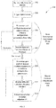
- FIGURE 2 shows a process 200 for optimizing performance in LTE network 100.
- process 200 adjusts antenna configuration parameters incrementally online, jointly, and per cluster.
- Process 200 observes the resultant feedback from measurement reports (MRs) transmitted by UE devices 104 and continues in a closed loop to optimize over the long run.
- Antenna configuration parameters include electronic tilt, azimuth, and reference symbol power.
- Feedback from actual UE devices 104 is used in the form of MRs, as opposed to propagation model estimates.
- the MRs can include multiple UE-related and cell-related parameters, such as cell ID, reference signal received power (RSRP), reference signal received quality (RSRQ), serving cell ID, and timing advance parameters.
- RSRP reference signal received power
- RSRQ reference signal received quality
- the information in the MRs is used to update an objective function representing network performance, identify cell state indicator metrics/labels, and make step-wise antenna configuration parameter adjustments for performance progress.
- an objective function can be used for optimization of a measurable quantity, parameter, or feature, such as network performance.
- the disclosed objective function can be used for optimization of network performance.
- Process 200 does not need to know where UE devices 104 are located within LTE network 100 nor the exact antenna configuration parameter values in order to optimize performance. This contrasts with propagation model aided solutions (such as ACP) that require accurate user location and correct antenna configuration parameter values for each cell. Because correct configuration parameter values are not known, even if initial configuration parameters are erroneous, the antenna configuration parameter values can still be adjusted in a meaningful direction due to the fact that parameter changes lead to measurable change in cell/system metrics. As long as MRs (RSRP, RSSINR or RSRQ) from representative UE devices 104 (e.g., UE devices 104 selected by unbiased random sampling) are available for a given antenna configuration parameter change, the objective function can be evaluated accurately.
- MRs RSRP, RSSINR or RSRQ
- every MR that is adjudged to have "failed" a coverage criterion e.g., by virtue of a reported reference channel signal strength not meeting a pre-defined threshold
- a quality criterion e.g., by virtue of a reported reference channel quality, i.e., signal to interference plus noise, not meeting another pre-defined threshold
- blame metrics can be calculated for each cell, and a base incremental action (e.g., antenna tilt or transmit power adjustment) can be taken by the cell in accordance with such blame metrics in order to reduce the rate of occurrence of MR failures.
- a base incremental action e.g., antenna tilt or transmit power adjustment
- Process 200 employs two closed loop phases - a base incremental adjustment phase 205 and a biased random adjustment phase 209.
- the base incremental adjustment phase 205 cell level features or blame metrics are calculated from the MRs and, alternatively or in addition, cells are labeled according to a coverage, quality, interference, or overshooter status (described in greater detail below with respect to FIGURES 4A-4E ) that map to "intuitively correct" adjustment directions for the antenna configuration parameters based on domain knowledge applied simultaneously on multiple cells in order to quickly grab big initial gains.
- MRs are processed to derive cell level metrics accounting for every cell's share of blame for measurement reports indicating inadequate coverage or quality.
- the cell level metrics determine what base incremental adjustments are made to that cell's antenna configuration parameters.
- MRs are processed to derive intuitive cell labels or combinations of cell labels indicating any of coverage, quality, interference, and overshooter status of each cell.
- the one or more labels attached to a cell determine the base incremental adjustments made to that cell's antenna configuration parameters.
- the biased random adjustment phase 209 represents a mathematical search procedure that performs explorative techniques and chooses oppositional or random initial directions. Adjustments are accepted when the objective function is improved and accepted with decreasing probability as the objective function worsens and with passage of time (cooling) to steadily improve the solution. Over time, exploration direction can be conditioned to learn from mistakes and, in a later explorative pass, the action learned to be best (in the sense of maximizing instantaneous or cumulative rewards) for a given cell state is chosen.
- the key facts being exploited are that the system objective function and cell level metrics are aggregations of UE state information (MR) that don't require individual UE locations for evaluation, and that parameter changes matter but not the absolute value.
- MR UE state information
- Process 200 begins at block 202 with the receipt of MRs from UE devices 104. Initiation of the optimization process is triggered at block 204. Optimization may be triggered manually, by network conditions, or automatically based on key performance indicators (KPIs) within LTE network 100. Examples of KPIs include call drop rate and call block rate. Other KPIs are known to those of skill in the art. If analysis of KPIs identify a degradation in network performance, then optimization is triggered. Upon triggering of optimization, process 200 proceeds to the base incremental adjustment phase 205, which includes blocks 206 and 208.
- KPIs key performance indicators
- MRs are used in block 206 to determine a direction of adjustment to the antenna configuration parameters (i.e., whether to adjust an antenna configuration parameter up or down). Only the direction of change is determined and not the specific current or starting values of the antenna configuration parameters.
- the direction of adjustment may be determined in several ways. In one example, the direction of change for each antenna configuration parameter is determined by a blame action metric where a majority rule of UE devices 104 provide MRs indicating a certain change in a direction (up or down) for a respective parameter. In another example, each cell is labeled with a cell status based on the MRs received from UE devices 104.
- a cell may be given one or more labels identifying a status of the cell, such as an interferer, non-interferer, good/weak coverage, good/weak quality, overshooter, and non-overshooter.
- interference refers to downlink interference in the cell.
- These labels are typically determined based on a comparison with one or more thresholds. The exact determination of these thresholds is beyond the scope of this disclosure.
- the labels given to a particular cell determine the change in direction for the antenna configuration parameters associated with that particular cell.
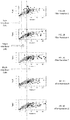
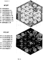
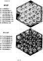
- FIGUREs 3A-3E show example graphs of global historical data categorizing interfering cells for a plurality of LTE networks.
- a cell is given an interferer label based on membership in a group cluster.
- the global historical data categorizes cells as non-interferer, single interferer, or multi-interferer, based on how many nearby cells experience interference from the given cell.
- the category a cell falls into determines its interferer label.
- the type of interferer label given to a particular cell determines the direction of adjustments made to the cell's antenna configuration parameters. After an adjustment is made to the antenna configuration parameters, a cell may fall into a different interferer category based on returned MRs from UE devices 104.
- FIGUREs 3A-3E show how cells may move across interferer categories during various iterations of the base incremental adjustment phase 205. For example, looking at the larger circular dots in FIGURES 3A-3E , it can be seen that many of the larger dots improve toward non-interferer status through iteration 9 ( FIGURE 3D ), but then cause greater interference and move to multi-interferer status in iteration 10 ( FIGURE 3E ).
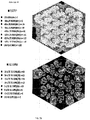
- FIGUREs 4A-4E show example graphs categorizing cells as overshooter cells.
- An example of an overshooter cell is a cell that provides a high reference signal received power (RSRP) to a UE device 104 but is located some distance from the UE device 104. That is, an overshooter cell causes significant interference from a comparatively far distance (e.g., further than an adjacent cell).
- a cell labeled as an overshooter may have a particular direction of adjustments made to its antenna configuration parameters (e.g, a down power or down tilt).
- a cell may fall out of or into an overshooter status based on new MRs from UE devices 104, where the new MRs are determined after the adjustment to the antenna configuration parameters.
- FIGUREs 4A-4E show how cells may move into and out of overshooter status during various iterations of the base incremental adjustment phase 205.
- the objective function for network optimization is calculated upon receiving new MRs in block 208 to determine if network performance improves.
- the objective function is based on a coverage parameter such as RSRP and a quality parameter such as signal to interference and noise ratio of the reference signal (RS-SINR).
- the objective function is determined by identifying those MRs having their RSRP parameter greater than a first threshold value and identifying those MRs having their RS-SINR parameter greater than a second threshold value.
- the objective function is calculated according to the equation: k 1 ⁇ number of RSRP > threshold 1 + k 2 ⁇ number of RS ⁇ SINR > threshold 2 , where k1 and k2 are non-negative numbers that sum to 1.0 and are determined in advance, e.g., by a system user (such as a network engineer) or automatically in a configuration routine. As long as network performance improves as indicated by an increase in the objective function, process 200 will loop through the base incremental adjustment phase 205 in blocks 206 and 208.
- the base incremental adjustment phase 205 ends and the biased random adjustment phase 209 including blocks 210, 212, and 214 begins.
- the biased random adjustment phase 209 simulated annealing is performed where random direction changes are made to the antenna configuration parameters and chaotic jumps are made to escape local minima positions in order to steadily improve the objective function toward a global optimum level.
- the biased random direction changes are accepted upon obtaining an improvement in the objective function. If the objective function decreases, a probability factor is used in determining whether to accept the random direction changes.
- Table I shows an example of a simulated annealing algorithm. Table I 1. Obtain initial solution S and position T 2. Determine C as the cost of S 3. Generate new solution S' 4.
- the simulated annealing process may identify a local maximum 502 but may perform a chaotic jump (from Jump 1 to Jump 2) in order to locate a global maximum 504.
- the maximums 502, 504 are determined maximums of the objective function described above.
- biased random adjustments are determined and performed in block 210. After the biased random adjustments have been made, new MRs are received and used to calculate the objective function in block 212. A determination is made as to whether to accept or discard the adjustments based at least on the recalculated objective function in block 214.
- biased random adjustments may be determined when the process 200 returns to block 210.
- the biased random adjustment phase 209 continues to loop through blocks 210, 212, and 214 and fine tune the parameters until a convergence to a global maximum is reached.
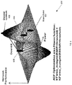
- FIGURE 6 shows a graph 600 of how the antenna configuration parameters of power and downtilt affect network performance (as measured by the objective function).
- the goal of process 200 is to identify a desired optimum network performance level 608 from a starting point 602.
- Process 200 is not aware of the particular starting point 602. Iterating through the base incremental adjustment phase 205 will attain a first intermediate network performance level 604.
- the biased random adjustment phase 209 will then kick in to perform chaotic jumps to identify the desired optimum network performance level 608, possibly through one or more second intermediate network performance levels 606.
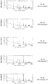
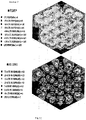
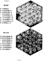
- FIGUREs 7A-7E show the changes to the two parameters provided in the measurement reports through several iterations of the base incremental adjustment phase 205.
- the first measured parameter is RSRP.
- RSRP is a measure of signal strength and identifies the signal level of the Reference Signal transmitted by an eNB radio access node 102 and received by a UE device 104.
- RSRP is used by UE devices 104 for cell selection and reselection process and is reported to the network to aid in a handover procedure.
- RSRP is defined as the linear average over the power contributions of the resource elements that carry cell-specific reference signals within the considered measurement frequency bandwidth.
- the second measured parameter is RS-SINR.
- RS-SINR is a measure of signal quality and quantifies the relationship between RF conditions and throughput.
- UE devices 104 typically use RS-SINR to calculate a Channel Quality Indicator (CQI) reported to the network.
- RS-SINR indicates the power of measured usable signals, the power of measured signals or channel interference signals from other cells in the current system, and background noise related to measurement bandwidths and receiver noise coefficients. Though the present disclosure focuses on RSRP and RS-SINR, there are other parameters provided in the measurement reports that are used in operation of LTE network 100.
- the measured parameters RSRP and RS-SINR improve through each successive iteration.
- a lack of growth in the objective function occurs and a degradation can start to occur in the performance characteristics. This lack of growth (and possible degradation) is referred to as an improvement limit.
- the RSRP and RS-SINR values begin to decrease in certain areas of LTE network 100.
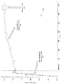
- FIGURE 8 shows a graph 800 depicting a change in the objective function through the iterations of the base incremental adjustment phase 205. Iteration numbers 1, 4, 7, 9, and 10 correspond to the results of the parameter adjustments shown in FIGUREs 7A-7E .
- the base incremental adjustments rapidly improve performance within LTE network 100, as indicated by the rapid increase in objective function value. The trend in continued performance improvement continues up until a certain point.
- base incremental adjustments to the antenna configuration parameters will reach an improvement limit where the objective function value does not increase (or increases only slightly) and may also provide improvement regression (e.g., a decrease in objective function value).
- the base incremental adjustment phase 205 Upon identifying a decrease in performance exceeding a desired threshold level, the base incremental adjustment phase 205 ends and the biased random adjustment phase 209 begins.
- a decrease in performance represented by the objective function occurs between iteration 9 and iteration 10. Approximately at iteration 9 is where the improvement limit occurs.
- FIGURE 9 shows a graph 900 depicting a change in the objective function through the iterations of the biased random adjustment phase 209.
- the biased random adjustment phase 209 continues until an optimum point 902 is reached representing a global maximum, such as global maximum 304 of FIGURE 3 or the desired optimum network performance level 408 of FIGURE 4 .
- FIGURE 10 illustrates a block diagram of a transceiver 1000 adapted to transmit and receive signaling over telecommunications network 100.
- One or more transceivers 1000 may be implemented in eNB radio access nodes 102 configured for optimizing cell specific antenna configuration parameters may be implemented, as described in the embodiments herein.
- the transceiver 1000 comprises a network-side interface 1002, a coupler 1004, a transmitter 1006, a receiver 1008, a signal processor 1010, and a device-side interface 1012.
- the network-side interface 1002 may include any component, circuitry, or combination thereof adapted to transmit or receive signaling over a wireless or wireline telecommunications network 100.
- the coupler 1004 may include any component or collection of components adapted to facilitate bi-directional communication over the network-side interface 1002.
- the transmitter 1006 may include any component or collection of components (e.g., up-converter, power amplifier, etc.) adapted to convert a baseband signal into a modulated carrier signal suitable for transmission over the network-side interface 1002.
- the receiver 1008 may include any component or collection of components (e.g., down-converter, low noise amplifier, etc.) adapted to convert a carrier signal received over the network-side interface 1002 into a baseband signal.
- the signal processor 1010 may include any component or collection of components adapted to convert a baseband signal into a data signal suitable for communication over the device-side interface(s) 1012, or vice-versa.
- the device-side interface(s) 1012 may include any component or collection of components adapted to communicate data-signals between the signal processor 1010 and components within the host device (e.g., UE devices 104, local area network (LAN) ports, etc.).
- the transceiver 1000 may transmit and receive signaling over any type of communications medium.
- the transceiver 1000 transmits and receives signaling over a wireless medium.
- the transceiver 1000 may be a wireless transceiver adapted to communicate in accordance with a wireless telecommunications protocol, such as a cellular protocol (e.g., long-term evolution (LTE), etc.), a wireless local area network (WLAN) protocol (e.g., Wi-Fi, etc.), or any other type of wireless protocol (e.g., Bluetooth, near field communication (NFC), etc.).
- the network-side interface 1002 comprises one or more antenna/radiating elements.
- the network-side interface 1002 may include a single antenna, multiple separate antennas, or a multi-antenna array configured for multi-layer communication, e.g., single input multiple output (SIMO), multiple input single output (MISO), multiple input multiple output (MIMO), etc.
- the transceiver 1000 transmits and receives signaling over a wireline medium, e.g., twisted-pair cable, coaxial cable, optical fiber, etc.
- Specific processing systems and/or transceivers may utilize all of the components shown, or only a subset of the components, and levels of integration may vary from device to device.
- FIGURE 11 illustrates a simplified example of a general-purpose computing component 1100 suitable for implementing one or more embodiments disclosed herein.
- Some of the features and embodiments described above for optimizing cell specific antenna configuration parameters may be implemented on any general-purpose computing component, such as a computer or network component with sufficient processing power, memory resources, and network throughput capability to handle the necessary workload placed upon it.
- computing component 1100 may be implemented in each eNB radio access node 102 or in a centralized server at the network level to perform the features described herein.
- the computing component 1100 includes a processor 1102 (which may be referred to as a central processor unit or CPU) that is in communication with memory devices including secondary storage 1104, read only memory (ROM) 1106, random access memory (RAM) 1108, input/output (I/O) devices 1110, and network/component connectivity devices 1112.
- the processor 1102 may be implemented as one or more CPU chips, or may be part of one or more application specific integrated circuits (ASICs).
- the secondary storage 1104 is typically comprised of one or more disk drives or tape drives and is used for non-volatile storage of data and as an over-flow data storage device if RAM 1108 is not large enough to hold all working data. Secondary storage 1104 may be used to store programs that are loaded into RAM 1108 when such programs are selected for execution.
- the ROM 1106 is used to store instructions and perhaps data that are read during program execution. ROM 1106 is a non-volatile memory device that typically has a small memory capacity relative to the larger memory capacity of secondary storage 1104.
- the RAM 1108 is used to store volatile data and perhaps to store instructions. Access to both ROM 1106 and RAM 1108 is typically faster than to secondary storage 1104.
- an analytics assisted fully automatic closed loop self-organizing network provides a general framework for solving large scale near real time network optimization problems (SON use cases)
- the optimization process disclosed herein learns online the environment via real-time feedback of UE MRs and cell KPIs using machine learning analytics to assign actionable metrics/labels to cells.
- the optimizing process self-adapts internal algorithm parameters (like metric thresholds) to changing circumstances (data) and learns the correct action rule for a given cell in a given state.
- Domain expertise and sophisticated processes are combined in phases for deciding joint corrective actions. This approach contrasts to other approaches that use ad hoc engineering knowledge based rules and unreliable models.
- the optimization process is robust to engineering parameter database errors and lack of knowledge of UE locations and has minimal modeling assumptions in contrast to expensive and unreliable UE location based optimization techniques.
- the optimization process is self-driving in that it uses machine learned cell labels or blame metrics with engineering knowledge guided small step actions to extract quick initial gains in network performance. For further optimization, action is taken in a biased random manner that balances reward with exploration risk.
- the optimization process learns from mistakes or wrong decisions with time to eventually pick a best action for a given cell state. As a result, the overall process is fast and outperforms engineers fazed by multi-cellular complex interactions.
- the optimization process provides a cost effective solution by reducing the need for an army of optimization engineers and expensive drive testing and model calibration.
- the optimization process may be readily extended to optimize additional CCO parameters like channel power offsets and CCO & Load Balancing (CCO+LB) scenarios.
- CCO+LB CCO & Load Balancing
- a system for adjusting cell specific antenna configuration parameters to improve network performance includes a receive module for receiving, at each of a plurality of radio access nodes in a network, measurement reports from a plurality of user equipment devices.
- the system further includes, at each of the radio access nodes, an adjustment module for performing base incremental adjustments to configuration parameters of one or more antennas at the radio access node in response to the measurement reports, wherein the measurement reports are processed to derive one or more of the following parameters on which the adjustments are based: cell level metrics accounting for every cell's share of blame for measurement reports indicating inadequate coverage or quality and cell label combinations indicating any of a coverage, quality, interference, or overshooter status of each cell.
- the system receive modules are configured for receiving, at each radio access node, additional measurement reports from the plurality of user equipment devices after the incremental adjustments and continue performing base incremental adjustments to the configuration parameters of the one or more antennas at the radio access nodes in response to the measurement reports after previous incremental adjustments until an improvement limit has occurred.
- the system adjustment modules are further configured to perform adjustments to the configuration parameters of the one or more antennas at the radio access nodes in accordance with a mathematical search procedure maximizing an objective function of coverage and quality in response to the improvement limit until a desired objective function value is achieved or for a certain number of iterations or until no further improvement is tangible.
- some or all of the functions or processes of the one or more of the devices are implemented or supported by a computer program that is formed from computer readable program code and that is embodied in a computer readable medium.
- code includes any type of computer code, including source code, object code, and executable code.
- computer readable medium includes any type of medium capable of being accessed by a computer, such as read only memory (ROM), random access memory (RAM), a hard disk drive, a compact disc (CD), a digital video disc (DVD), or any other type of memory.
- ROM read only memory
- RAM random access memory
- CD compact disc
- DVD digital video disc
- the computer program may detect core traces, convert the core traces into a hierarchical format, generate the gene function database, and determine preemption costs associated with the gene functions.
Landscapes
- Engineering & Computer Science (AREA)
- Computer Networks & Wireless Communication (AREA)
- Signal Processing (AREA)
- Mobile Radio Communication Systems (AREA)
Applications Claiming Priority (7)
| Application Number | Priority Date | Filing Date | Title |
|---|---|---|---|
| US201462089654P | 2014-12-09 | 2014-12-09 | |
| US201462093283P | 2014-12-17 | 2014-12-17 | |
| US201462096439P | 2014-12-23 | 2014-12-23 | |
| US201562099854P | 2015-01-05 | 2015-01-05 | |
| US201562100003P | 2015-01-05 | 2015-01-05 | |
| US14/963,062 US9769689B2 (en) | 2014-12-09 | 2015-12-08 | Method and apparatus for optimizing cell specific antenna configuration parameters |
| PCT/CN2015/096816 WO2016091171A1 (en) | 2014-12-09 | 2015-12-09 | Method and apparatus for optimizing cell specific antenna configuration parameters |
Publications (3)
| Publication Number | Publication Date |
|---|---|
| EP3225045A1 EP3225045A1 (en) | 2017-10-04 |
| EP3225045A4 EP3225045A4 (en) | 2017-11-08 |
| EP3225045B1 true EP3225045B1 (en) | 2020-08-05 |
Family
ID=56095568
Family Applications (1)
| Application Number | Title | Priority Date | Filing Date |
|---|---|---|---|
| EP15867201.4A Active EP3225045B1 (en) | 2014-12-09 | 2015-12-09 | Method and apparatus for optimizing cell specific antenna configuration parameters |
Country Status (4)
| Country | Link |
|---|---|
| US (1) | US9769689B2 (da) |
| EP (1) | EP3225045B1 (da) |
| CN (1) | CN107113634B (da) |
| WO (1) | WO2016091171A1 (da) |
Families Citing this family (22)
| Publication number | Priority date | Publication date | Assignee | Title |
|---|---|---|---|---|
| US10785101B2 (en) | 2017-08-23 | 2020-09-22 | Futurewei Technologies, Inc. | Automatically optimize parameters via machine learning |
| CN109495914B (zh) * | 2017-09-11 | 2022-04-01 | 中国移动通信集团云南有限公司 | 一种识别深度覆盖小区的方法及装置 |
| CN109787792B (zh) * | 2017-11-10 | 2022-05-13 | 阿里巴巴集团控股有限公司 | 一种管理分布式业务集群的系统 |
| CN109905287B (zh) * | 2018-05-21 | 2021-02-12 | 华为技术有限公司 | 性能指标校准方法及装置 |
| US10645604B2 (en) * | 2018-06-04 | 2020-05-05 | Verizon Patent And Licensing Inc. | Intelligent optimization of cells in a mobile network |
| CN111328103B (zh) * | 2018-12-17 | 2023-04-11 | 中国移动通信集团吉林有限公司 | 一种天线覆盖调整的方法和装置 |
| CN109743685A (zh) * | 2018-12-25 | 2019-05-10 | 中国联合网络通信集团有限公司 | 基站覆盖区域分析方法、设备及存储介质 |
| CN111372265B (zh) * | 2018-12-26 | 2022-08-30 | 中国电信股份有限公司 | 天线参数配置方法、装置、系统及计算机可读存储介质 |
| CN112243249B (zh) * | 2019-07-19 | 2022-05-20 | 大唐移动通信设备有限公司 | 5g nsa组网下lte新入网锚点小区参数配置方法和装置 |
| WO2021061176A1 (en) * | 2019-09-27 | 2021-04-01 | Nokia Technologies Oy | Method, apparatus and computer program for user equipment localization |
| EP4044752B1 (en) * | 2019-11-04 | 2026-01-07 | Huawei Technologies Co., Ltd. | Communication methods, communication apparatuses, computer storage medium and computer program product |
| CN111405597B (zh) * | 2020-02-26 | 2020-12-29 | 中通服建设有限公司 | 基站天线覆盖异变自动监测方法及系统 |
| US20230262521A1 (en) * | 2020-07-07 | 2023-08-17 | Telefonaktiebolaget Lm Ericsson (Publ) | Traffic load management |
| FI20205781A1 (en) * | 2020-08-04 | 2022-02-05 | Nokia Technologies Oy | MACHINE LEARNING BASED COUPLING OF AN ANTENNA PANEL |
| US12563426B2 (en) * | 2020-10-02 | 2026-02-24 | Valea Ab | Technique for assessing connection quality |
| CN114339781B (zh) * | 2020-10-10 | 2023-12-05 | 大唐移动通信设备有限公司 | 无线网络覆盖优化方法和装置、电子设备、存储介质 |
| CN114818452A (zh) * | 2021-01-19 | 2022-07-29 | 华为技术服务有限公司 | 天线配置参数优化方法、装置及存储介质 |
| TWI767599B (zh) * | 2021-03-08 | 2022-06-11 | 國立陽明交通大學 | 體驗品質優化系統及方法 |
| CN115052303B (zh) * | 2021-04-25 | 2026-03-24 | 四川通信科研规划设计有限责任公司 | 基于栅格rsrp数据的基站方向角纠偏方法、存储介质和装置 |
| US11671316B2 (en) * | 2021-06-23 | 2023-06-06 | At&T Intellectual Property I, L.P. | Generating and utilizing provisioning templates to provision voice, video, and data communication services |
| CN114786194B (zh) * | 2022-03-23 | 2025-02-18 | 南京晓庄学院 | 一种雾接入点范围扩展偏置与发送功率联合调整方法 |
| CN117729560A (zh) * | 2022-09-19 | 2024-03-19 | 中兴通讯股份有限公司 | 一种天线参数的确定方法及装置 |
Family Cites Families (30)
| Publication number | Priority date | Publication date | Assignee | Title |
|---|---|---|---|---|
| US7151506B2 (en) | 2003-04-11 | 2006-12-19 | Qortek, Inc. | Electromagnetic energy coupling mechanism with matrix architecture control |
| GB2461242B (en) * | 2007-09-14 | 2010-06-30 | Actix Ltd | Mobile phone network management systems |
| CN101557654B (zh) | 2008-04-07 | 2013-05-08 | 中兴通讯股份有限公司 | 网络覆盖优化处理方法和系统 |
| US8072914B2 (en) | 2008-05-08 | 2011-12-06 | At&T Mobility Ii Llc | Location survey for power calibration in a femto cell |
| WO2010051838A1 (en) * | 2008-11-05 | 2010-05-14 | Nokia Siemens Networks Oy | Method of improving coverage and optimisation in communication networks |
| US8514790B2 (en) * | 2009-01-22 | 2013-08-20 | Intel Mobile Communications GmbH | System and method for optimizing network wireless communication resources |
| US20100238984A1 (en) * | 2009-03-19 | 2010-09-23 | Motorola, Inc. | Spatial Information Feedback in Wireless Communication Systems |
| KR101100688B1 (ko) | 2009-08-06 | 2012-01-03 | 주식회사 이노와이어리스 | 안테나 방향을 조절할 수 있는 중계기 및 셀 최적화 방법 |
| WO2011050971A1 (en) | 2009-10-30 | 2011-05-05 | Telefonaktiebolaget L M Ericsson (Publ) | User equipment reporting of connection loss |
| EP2499751A4 (en) * | 2009-11-09 | 2014-08-27 | Ericsson Telefon Ab L M | METHOD AND ARRANGEMENT FOR POLARIZATION ADJUSTMENT FOR ORTHOGONALLY POLARIZED ANTENNAS |
| US8559957B2 (en) * | 2010-01-28 | 2013-10-15 | Qualcomm Incorporated | Method and apparatus for biasing a handoff decision based on a blackhaul link |
| US9264954B2 (en) | 2010-04-28 | 2016-02-16 | Qualcomm Incorporated | Neighbor relation information management |
| US8712402B2 (en) | 2010-05-18 | 2014-04-29 | At&T Intellectual Property I, L.P. | Enabling improvement in cellular network coverage |
| CN102300221B (zh) | 2010-06-25 | 2016-03-30 | 中兴通讯股份有限公司 | 一种利用天线调整小区覆盖的系统、装置及方法 |
| CN102202330B (zh) | 2011-05-23 | 2014-07-16 | 北京邮电大学 | 蜂窝移动通信系统的覆盖自优化方法 |
| US8738022B2 (en) * | 2011-10-06 | 2014-05-27 | Futurewei Technologies, Inc. | System and methods for beam shaping in a self-organizing network |
| CN103220699B (zh) | 2012-01-19 | 2016-01-27 | 华为技术有限公司 | 评估网络性能的方法和装置 |
| CN103384376B (zh) | 2012-05-04 | 2016-12-14 | 华为技术有限公司 | 链路覆盖问题确定方法、装置与系统 |
| US8995255B2 (en) | 2012-08-03 | 2015-03-31 | Intel Corporation | Coverage adjustment in E-UTRA networks |
| AU2013300190A1 (en) * | 2012-08-07 | 2015-02-26 | Telefonaktiebolaget L M Ericsson (Publ) | Method and apparatus in a multi-carrier system for controlling interruption and measurement performance |
| EP2723123A1 (en) * | 2012-10-18 | 2014-04-23 | Alcatel Lucent | Autonomous determination of optimal values for handover parameters |
| CN103906073B (zh) | 2012-12-28 | 2017-10-17 | 华为技术有限公司 | 覆盖和容量优化方法、设备和系统 |
| CN103152755B (zh) | 2013-02-28 | 2015-10-28 | 深圳市网信联动通信技术股份有限公司 | 一种小区信号精细化覆盖调整方法及装置 |
| EP2962485B1 (en) | 2013-03-01 | 2019-08-21 | Intel IP Corporation | Wireless local area network (wlan) traffic offloading |
| CN104053222B (zh) * | 2013-03-14 | 2017-07-14 | 电信科学技术研究院 | 基站发射功率调整方法和装置 |
| CN104521268B (zh) | 2013-05-27 | 2019-02-19 | 华为技术有限公司 | 一种信号质量测量信息的上报方法和设备 |
| US9401874B2 (en) | 2013-08-14 | 2016-07-26 | Qualcomm Incorporated | Minimizing coverage holes in a communication network |
| US9781685B2 (en) | 2013-11-21 | 2017-10-03 | At&T Intellectual Property I, L.P. | Self-adaptive coverage of wireless networks |
| US9408095B2 (en) | 2014-02-05 | 2016-08-02 | Telefonaktiebolaget L M Ericsson (Publ) | Autonomous determination of overlapping coverage in heterogeneous networks |
| US20160029253A1 (en) | 2014-07-28 | 2016-01-28 | Telefonaktiebolaget L M Ericsson (Publ) | System and method of automatic neighbor relation (anr) intelligence enhancement for boomer neighbor in lte |
-
2015
- 2015-12-08 US US14/963,062 patent/US9769689B2/en active Active
- 2015-12-09 WO PCT/CN2015/096816 patent/WO2016091171A1/en not_active Ceased
- 2015-12-09 EP EP15867201.4A patent/EP3225045B1/en active Active
- 2015-12-09 CN CN201580066317.8A patent/CN107113634B/zh not_active Expired - Fee Related
Non-Patent Citations (1)
| Title |
|---|
| None * |
Also Published As
| Publication number | Publication date |
|---|---|
| EP3225045A4 (en) | 2017-11-08 |
| EP3225045A1 (en) | 2017-10-04 |
| WO2016091171A1 (en) | 2016-06-16 |
| US9769689B2 (en) | 2017-09-19 |
| CN107113634A (zh) | 2017-08-29 |
| US20160165468A1 (en) | 2016-06-09 |
| CN107113634B (zh) | 2020-07-14 |
Similar Documents
| Publication | Publication Date | Title |
|---|---|---|
| EP3225045B1 (en) | Method and apparatus for optimizing cell specific antenna configuration parameters | |
| EP3225046B1 (en) | Method and apparatus for determining cell states to adjust antenna configuration parameters | |
| US9578530B2 (en) | Method and apparatus for determining cell states to adjust antenna configuration parameters | |
| US10327159B2 (en) | Autonomous, closed-loop and adaptive simulated annealing based machine learning approach for intelligent analytics-assisted self-organizing-networks (SONs) | |
| US20160165472A1 (en) | Analytics assisted self-organizing-network (SON) for coverage capacity optimization (CCO) | |
| US10382979B2 (en) | Self-learning, adaptive approach for intelligent analytics-assisted self-organizing-networks (SONs) | |
| EP3241379B1 (en) | Analytics-assisted, multi-agents, self-learning, self-managing, flexible and adaptive framework for intelligent son | |
| US10911318B2 (en) | Future network condition predictor for network time series data utilizing a hidden Markov model for non-anomalous data and a gaussian mixture model for anomalous data | |
| US10374882B2 (en) | Systems and methods for identifying causes of quality degradation in wireless networks | |
| US9756518B1 (en) | Method and apparatus for detecting a traffic suppression turning point in a cellular network | |
| WO2017050113A1 (en) | System and method for a multi view learning approach to anomaly detection and root cause analysis | |
| EP4136782B1 (en) | Channel state information values-based estimation of reference signal received power values for wireless networks | |
| US9531605B2 (en) | Determination of radiation beam pattern | |
| US20240179566A1 (en) | Method and device for performing load balance in wireless communication system | |
| US12556947B2 (en) | Reward simulation for reinforcement learning for wireless network | |
| US20260066970A1 (en) | Channel state information switching prediction | |
| WO2025201657A1 (en) | Reward simulation for reinforcement learning for wireless network | |
| KR20230019799A (ko) | 무선 통신 시스템에서 로드 밸런스를 수행하기 위한 방법 및 장치 | |
| US20120243425A1 (en) | Power management method for use in a wireless network system |
Legal Events
| Date | Code | Title | Description |
|---|---|---|---|
| STAA | Information on the status of an ep patent application or granted ep patent |
Free format text: STATUS: THE INTERNATIONAL PUBLICATION HAS BEEN MADE |
|
| PUAI | Public reference made under article 153(3) epc to a published international application that has entered the european phase |
Free format text: ORIGINAL CODE: 0009012 |
|
| STAA | Information on the status of an ep patent application or granted ep patent |
Free format text: STATUS: REQUEST FOR EXAMINATION WAS MADE |
|
| 17P | Request for examination filed |
Effective date: 20170628 |
|
| AK | Designated contracting states |
Kind code of ref document: A1 Designated state(s): AL AT BE BG CH CY CZ DE DK EE ES FI FR GB GR HR HU IE IS IT LI LT LU LV MC MK MT NL NO PL PT RO RS SE SI SK SM TR |
|
| AX | Request for extension of the european patent |
Extension state: BA ME |
|
| A4 | Supplementary search report drawn up and despatched |
Effective date: 20171009 |
|
| RIC1 | Information provided on ipc code assigned before grant |
Ipc: H04W 24/02 20090101AFI20171002BHEP Ipc: H04W 88/08 20090101ALN20171002BHEP |
|
| RIN1 | Information on inventor provided before grant (corrected) |
Inventor name: XIN, YAN Inventor name: YANG, JIN Inventor name: MATHEW, JAMES Inventor name: GOPALAKRISHNAN, NANDU Inventor name: TAN, YONGXI |
|
| DAV | Request for validation of the european patent (deleted) | ||
| DAX | Request for extension of the european patent (deleted) | ||
| STAA | Information on the status of an ep patent application or granted ep patent |
Free format text: STATUS: EXAMINATION IS IN PROGRESS |
|
| 17Q | First examination report despatched |
Effective date: 20180921 |
|
| RIC1 | Information provided on ipc code assigned before grant |
Ipc: H04W 24/02 20090101AFI20200131BHEP Ipc: H04W 88/08 20090101ALN20200131BHEP |
|
| GRAP | Despatch of communication of intention to grant a patent |
Free format text: ORIGINAL CODE: EPIDOSNIGR1 |
|
| STAA | Information on the status of an ep patent application or granted ep patent |
Free format text: STATUS: GRANT OF PATENT IS INTENDED |
|
| INTG | Intention to grant announced |
Effective date: 20200326 |
|
| GRAS | Grant fee paid |
Free format text: ORIGINAL CODE: EPIDOSNIGR3 |
|
| GRAA | (expected) grant |
Free format text: ORIGINAL CODE: 0009210 |
|
| STAA | Information on the status of an ep patent application or granted ep patent |
Free format text: STATUS: THE PATENT HAS BEEN GRANTED |
|
| AK | Designated contracting states |
Kind code of ref document: B1 Designated state(s): AL AT BE BG CH CY CZ DE DK EE ES FI FR GB GR HR HU IE IS IT LI LT LU LV MC MK MT NL NO PL PT RO RS SE SI SK SM TR |
|
| REG | Reference to a national code |
Ref country code: GB Ref legal event code: FG4D |
|
| REG | Reference to a national code |
Ref country code: CH Ref legal event code: EP |
|
| REG | Reference to a national code |
Ref country code: AT Ref legal event code: REF Ref document number: 1300458 Country of ref document: AT Kind code of ref document: T Effective date: 20200815 |
|
| REG | Reference to a national code |
Ref country code: DE Ref legal event code: R096 Ref document number: 602015057167 Country of ref document: DE |
|
| REG | Reference to a national code |
Ref country code: IE Ref legal event code: FG4D |
|
| REG | Reference to a national code |
Ref country code: LT Ref legal event code: MG4D |
|
| REG | Reference to a national code |
Ref country code: NL Ref legal event code: MP Effective date: 20200805 |
|
| REG | Reference to a national code |
Ref country code: AT Ref legal event code: MK05 Ref document number: 1300458 Country of ref document: AT Kind code of ref document: T Effective date: 20200805 |
|
| PG25 | Lapsed in a contracting state [announced via postgrant information from national office to epo] |
Ref country code: SE Free format text: LAPSE BECAUSE OF FAILURE TO SUBMIT A TRANSLATION OF THE DESCRIPTION OR TO PAY THE FEE WITHIN THE PRESCRIBED TIME-LIMIT Effective date: 20200805 Ref country code: LT Free format text: LAPSE BECAUSE OF FAILURE TO SUBMIT A TRANSLATION OF THE DESCRIPTION OR TO PAY THE FEE WITHIN THE PRESCRIBED TIME-LIMIT Effective date: 20200805 Ref country code: FI Free format text: LAPSE BECAUSE OF FAILURE TO SUBMIT A TRANSLATION OF THE DESCRIPTION OR TO PAY THE FEE WITHIN THE PRESCRIBED TIME-LIMIT Effective date: 20200805 Ref country code: HR Free format text: LAPSE BECAUSE OF FAILURE TO SUBMIT A TRANSLATION OF THE DESCRIPTION OR TO PAY THE FEE WITHIN THE PRESCRIBED TIME-LIMIT Effective date: 20200805 Ref country code: AT Free format text: LAPSE BECAUSE OF FAILURE TO SUBMIT A TRANSLATION OF THE DESCRIPTION OR TO PAY THE FEE WITHIN THE PRESCRIBED TIME-LIMIT Effective date: 20200805 Ref country code: BG Free format text: LAPSE BECAUSE OF FAILURE TO SUBMIT A TRANSLATION OF THE DESCRIPTION OR TO PAY THE FEE WITHIN THE PRESCRIBED TIME-LIMIT Effective date: 20201105 Ref country code: GR Free format text: LAPSE BECAUSE OF FAILURE TO SUBMIT A TRANSLATION OF THE DESCRIPTION OR TO PAY THE FEE WITHIN THE PRESCRIBED TIME-LIMIT Effective date: 20201106 Ref country code: NO Free format text: LAPSE BECAUSE OF FAILURE TO SUBMIT A TRANSLATION OF THE DESCRIPTION OR TO PAY THE FEE WITHIN THE PRESCRIBED TIME-LIMIT Effective date: 20201105 Ref country code: ES Free format text: LAPSE BECAUSE OF FAILURE TO SUBMIT A TRANSLATION OF THE DESCRIPTION OR TO PAY THE FEE WITHIN THE PRESCRIBED TIME-LIMIT Effective date: 20200805 Ref country code: PT Free format text: LAPSE BECAUSE OF FAILURE TO SUBMIT A TRANSLATION OF THE DESCRIPTION OR TO PAY THE FEE WITHIN THE PRESCRIBED TIME-LIMIT Effective date: 20201207 |
|
| PG25 | Lapsed in a contracting state [announced via postgrant information from national office to epo] |
Ref country code: IS Free format text: LAPSE BECAUSE OF FAILURE TO SUBMIT A TRANSLATION OF THE DESCRIPTION OR TO PAY THE FEE WITHIN THE PRESCRIBED TIME-LIMIT Effective date: 20201205 Ref country code: NL Free format text: LAPSE BECAUSE OF FAILURE TO SUBMIT A TRANSLATION OF THE DESCRIPTION OR TO PAY THE FEE WITHIN THE PRESCRIBED TIME-LIMIT Effective date: 20200805 Ref country code: RS Free format text: LAPSE BECAUSE OF FAILURE TO SUBMIT A TRANSLATION OF THE DESCRIPTION OR TO PAY THE FEE WITHIN THE PRESCRIBED TIME-LIMIT Effective date: 20200805 Ref country code: PL Free format text: LAPSE BECAUSE OF FAILURE TO SUBMIT A TRANSLATION OF THE DESCRIPTION OR TO PAY THE FEE WITHIN THE PRESCRIBED TIME-LIMIT Effective date: 20200805 Ref country code: LV Free format text: LAPSE BECAUSE OF FAILURE TO SUBMIT A TRANSLATION OF THE DESCRIPTION OR TO PAY THE FEE WITHIN THE PRESCRIBED TIME-LIMIT Effective date: 20200805 |
|
| PG25 | Lapsed in a contracting state [announced via postgrant information from national office to epo] |
Ref country code: CZ Free format text: LAPSE BECAUSE OF FAILURE TO SUBMIT A TRANSLATION OF THE DESCRIPTION OR TO PAY THE FEE WITHIN THE PRESCRIBED TIME-LIMIT Effective date: 20200805 Ref country code: DK Free format text: LAPSE BECAUSE OF FAILURE TO SUBMIT A TRANSLATION OF THE DESCRIPTION OR TO PAY THE FEE WITHIN THE PRESCRIBED TIME-LIMIT Effective date: 20200805 Ref country code: EE Free format text: LAPSE BECAUSE OF FAILURE TO SUBMIT A TRANSLATION OF THE DESCRIPTION OR TO PAY THE FEE WITHIN THE PRESCRIBED TIME-LIMIT Effective date: 20200805 Ref country code: RO Free format text: LAPSE BECAUSE OF FAILURE TO SUBMIT A TRANSLATION OF THE DESCRIPTION OR TO PAY THE FEE WITHIN THE PRESCRIBED TIME-LIMIT Effective date: 20200805 Ref country code: SM Free format text: LAPSE BECAUSE OF FAILURE TO SUBMIT A TRANSLATION OF THE DESCRIPTION OR TO PAY THE FEE WITHIN THE PRESCRIBED TIME-LIMIT Effective date: 20200805 |
|
| REG | Reference to a national code |
Ref country code: DE Ref legal event code: R097 Ref document number: 602015057167 Country of ref document: DE |
|
| PG25 | Lapsed in a contracting state [announced via postgrant information from national office to epo] |
Ref country code: AL Free format text: LAPSE BECAUSE OF FAILURE TO SUBMIT A TRANSLATION OF THE DESCRIPTION OR TO PAY THE FEE WITHIN THE PRESCRIBED TIME-LIMIT Effective date: 20200805 |
|
| PLBE | No opposition filed within time limit |
Free format text: ORIGINAL CODE: 0009261 |
|
| STAA | Information on the status of an ep patent application or granted ep patent |
Free format text: STATUS: NO OPPOSITION FILED WITHIN TIME LIMIT |
|
| PG25 | Lapsed in a contracting state [announced via postgrant information from national office to epo] |
Ref country code: SK Free format text: LAPSE BECAUSE OF FAILURE TO SUBMIT A TRANSLATION OF THE DESCRIPTION OR TO PAY THE FEE WITHIN THE PRESCRIBED TIME-LIMIT Effective date: 20200805 |
|
| REG | Reference to a national code |
Ref country code: DE Ref legal event code: R119 Ref document number: 602015057167 Country of ref document: DE |
|
| 26N | No opposition filed |
Effective date: 20210507 |
|
| PG25 | Lapsed in a contracting state [announced via postgrant information from national office to epo] |
Ref country code: IT Free format text: LAPSE BECAUSE OF FAILURE TO SUBMIT A TRANSLATION OF THE DESCRIPTION OR TO PAY THE FEE WITHIN THE PRESCRIBED TIME-LIMIT Effective date: 20200805 |
|
| REG | Reference to a national code |
Ref country code: CH Ref legal event code: PL |
|
| PG25 | Lapsed in a contracting state [announced via postgrant information from national office to epo] |
Ref country code: SI Free format text: LAPSE BECAUSE OF FAILURE TO SUBMIT A TRANSLATION OF THE DESCRIPTION OR TO PAY THE FEE WITHIN THE PRESCRIBED TIME-LIMIT Effective date: 20200805 Ref country code: MC Free format text: LAPSE BECAUSE OF FAILURE TO SUBMIT A TRANSLATION OF THE DESCRIPTION OR TO PAY THE FEE WITHIN THE PRESCRIBED TIME-LIMIT Effective date: 20200805 |
|
| REG | Reference to a national code |
Ref country code: BE Ref legal event code: MM Effective date: 20201231 |
|
| PG25 | Lapsed in a contracting state [announced via postgrant information from national office to epo] |
Ref country code: FR Free format text: LAPSE BECAUSE OF NON-PAYMENT OF DUE FEES Effective date: 20201231 Ref country code: LU Free format text: LAPSE BECAUSE OF NON-PAYMENT OF DUE FEES Effective date: 20201209 Ref country code: IE Free format text: LAPSE BECAUSE OF NON-PAYMENT OF DUE FEES Effective date: 20201209 |
|
| PG25 | Lapsed in a contracting state [announced via postgrant information from national office to epo] |
Ref country code: LI Free format text: LAPSE BECAUSE OF NON-PAYMENT OF DUE FEES Effective date: 20201231 Ref country code: DE Free format text: LAPSE BECAUSE OF NON-PAYMENT OF DUE FEES Effective date: 20210701 Ref country code: CH Free format text: LAPSE BECAUSE OF NON-PAYMENT OF DUE FEES Effective date: 20201231 |
|
| PG25 | Lapsed in a contracting state [announced via postgrant information from national office to epo] |
Ref country code: TR Free format text: LAPSE BECAUSE OF FAILURE TO SUBMIT A TRANSLATION OF THE DESCRIPTION OR TO PAY THE FEE WITHIN THE PRESCRIBED TIME-LIMIT Effective date: 20200805 Ref country code: MT Free format text: LAPSE BECAUSE OF FAILURE TO SUBMIT A TRANSLATION OF THE DESCRIPTION OR TO PAY THE FEE WITHIN THE PRESCRIBED TIME-LIMIT Effective date: 20200805 Ref country code: CY Free format text: LAPSE BECAUSE OF FAILURE TO SUBMIT A TRANSLATION OF THE DESCRIPTION OR TO PAY THE FEE WITHIN THE PRESCRIBED TIME-LIMIT Effective date: 20200805 |
|
| PG25 | Lapsed in a contracting state [announced via postgrant information from national office to epo] |
Ref country code: MK Free format text: LAPSE BECAUSE OF FAILURE TO SUBMIT A TRANSLATION OF THE DESCRIPTION OR TO PAY THE FEE WITHIN THE PRESCRIBED TIME-LIMIT Effective date: 20200805 |
|
| PG25 | Lapsed in a contracting state [announced via postgrant information from national office to epo] |
Ref country code: BE Free format text: LAPSE BECAUSE OF NON-PAYMENT OF DUE FEES Effective date: 20201231 |
|
| PGFP | Annual fee paid to national office [announced via postgrant information from national office to epo] |
Ref country code: GB Payment date: 20251030 Year of fee payment: 11 |