EP3224902B1 - Monitoring apparatus for a transmitting antenna system and method for monitoring a transmitting antenna system - Google Patents
Monitoring apparatus for a transmitting antenna system and method for monitoring a transmitting antenna system Download PDFInfo
- Publication number
- EP3224902B1 EP3224902B1 EP15767114.0A EP15767114A EP3224902B1 EP 3224902 B1 EP3224902 B1 EP 3224902B1 EP 15767114 A EP15767114 A EP 15767114A EP 3224902 B1 EP3224902 B1 EP 3224902B1
- Authority
- EP
- European Patent Office
- Prior art keywords
- signal
- antenna system
- measuring
- transmitting antenna
- resistance
- Prior art date
- Legal status (The legal status is an assumption and is not a legal conclusion. Google has not performed a legal analysis and makes no representation as to the accuracy of the status listed.)
- Active
Links
- 238000012544 monitoring process Methods 0.000 title claims description 33
- 238000000034 method Methods 0.000 title claims description 32
- 230000005540 biological transmission Effects 0.000 claims description 81
- 239000004020 conductor Substances 0.000 claims description 47
- 238000012806 monitoring device Methods 0.000 claims description 33
- 238000010079 rubber tapping Methods 0.000 claims description 27
- 238000011156 evaluation Methods 0.000 claims description 21
- 230000003287 optical effect Effects 0.000 claims description 8
- 230000009849 deactivation Effects 0.000 claims 3
- 241000237519 Bivalvia Species 0.000 claims 1
- 235000020639 clam Nutrition 0.000 claims 1
- 238000005259 measurement Methods 0.000 description 84
- 230000008878 coupling Effects 0.000 description 32
- 238000010168 coupling process Methods 0.000 description 32
- 238000005859 coupling reaction Methods 0.000 description 32
- 238000009413 insulation Methods 0.000 description 24
- 238000001514 detection method Methods 0.000 description 18
- 238000009434 installation Methods 0.000 description 16
- 239000003990 capacitor Substances 0.000 description 15
- 230000006378 damage Effects 0.000 description 15
- 230000008901 benefit Effects 0.000 description 11
- 238000010586 diagram Methods 0.000 description 11
- 238000013461 design Methods 0.000 description 9
- 230000001960 triggered effect Effects 0.000 description 8
- 238000001228 spectrum Methods 0.000 description 6
- 230000007704 transition Effects 0.000 description 6
- 230000006978 adaptation Effects 0.000 description 5
- 238000011161 development Methods 0.000 description 5
- 230000018109 developmental process Effects 0.000 description 5
- 238000012360 testing method Methods 0.000 description 5
- 230000007257 malfunction Effects 0.000 description 3
- 239000000463 material Substances 0.000 description 3
- 230000008569 process Effects 0.000 description 3
- 230000008439 repair process Effects 0.000 description 3
- 230000004913 activation Effects 0.000 description 2
- 230000033228 biological regulation Effects 0.000 description 2
- 230000015572 biosynthetic process Effects 0.000 description 2
- 239000000919 ceramic Substances 0.000 description 2
- 230000008859 change Effects 0.000 description 2
- 238000010276 construction Methods 0.000 description 2
- 230000007797 corrosion Effects 0.000 description 2
- 238000005260 corrosion Methods 0.000 description 2
- 230000007547 defect Effects 0.000 description 2
- 230000007812 deficiency Effects 0.000 description 2
- 230000001066 destructive effect Effects 0.000 description 2
- 238000005516 engineering process Methods 0.000 description 2
- 238000012423 maintenance Methods 0.000 description 2
- 230000005012 migration Effects 0.000 description 2
- 238000013508 migration Methods 0.000 description 2
- 239000003595 mist Substances 0.000 description 2
- 238000000926 separation method Methods 0.000 description 2
- XLYOFNOQVPJJNP-UHFFFAOYSA-N water Substances O XLYOFNOQVPJJNP-UHFFFAOYSA-N 0.000 description 2
- 241000881711 Acipenser sturio Species 0.000 description 1
- 241000475481 Nebula Species 0.000 description 1
- 229910000831 Steel Inorganic materials 0.000 description 1
- 230000002159 abnormal effect Effects 0.000 description 1
- 230000032683 aging Effects 0.000 description 1
- 230000000739 chaotic effect Effects 0.000 description 1
- 238000004891 communication Methods 0.000 description 1
- 238000009833 condensation Methods 0.000 description 1
- 230000005494 condensation Effects 0.000 description 1
- 238000013016 damping Methods 0.000 description 1
- 238000000354 decomposition reaction Methods 0.000 description 1
- 230000002950 deficient Effects 0.000 description 1
- 230000000694 effects Effects 0.000 description 1
- 238000001704 evaporation Methods 0.000 description 1
- 230000008020 evaporation Effects 0.000 description 1
- 230000003993 interaction Effects 0.000 description 1
- 230000002452 interceptive effect Effects 0.000 description 1
- 230000009191 jumping Effects 0.000 description 1
- 238000006386 neutralization reaction Methods 0.000 description 1
- 230000035515 penetration Effects 0.000 description 1
- 238000000053 physical method Methods 0.000 description 1
- 238000001303 quality assessment method Methods 0.000 description 1
- 230000009467 reduction Effects 0.000 description 1
- 239000000779 smoke Substances 0.000 description 1
- 230000002269 spontaneous effect Effects 0.000 description 1
- 239000010959 steel Substances 0.000 description 1
- 230000000007 visual effect Effects 0.000 description 1
Images


Classifications
-
- H—ELECTRICITY
- H01—ELECTRIC ELEMENTS
- H01Q—ANTENNAS, i.e. RADIO AERIALS
- H01Q1/00—Details of, or arrangements associated with, antennas
- H01Q1/50—Structural association of antennas with earthing switches, lead-in devices or lightning protectors
-
- H—ELECTRICITY
- H04—ELECTRIC COMMUNICATION TECHNIQUE
- H04B—TRANSMISSION
- H04B1/00—Details of transmission systems, not covered by a single one of groups H04B3/00 - H04B13/00; Details of transmission systems not characterised by the medium used for transmission
- H04B1/02—Transmitters
- H04B1/04—Circuits
- H04B1/0475—Circuits with means for limiting noise, interference or distortion
Definitions
- the present invention relates to a transmission antenna system monitoring device with an arcing sensor. Furthermore, a transmission antenna system monitoring device with several monitoring modules for the respective monitoring of different electrical parameters of the transmission antenna system is proposed.
- the invention also includes a method for monitoring a transmitting antenna system by means of at least one arc sensor.
- the detection device In the detection device according to the document DE-A-10 2015 001 493 there is no provision for evaluating the detection signal in a low-frequency range between 0 and 60 kHz. Also, the cited document does not provide for the detection signal to be coupled out by direct, galvanic connection to the inner conductor.
- WO-A-2014/032 650 describes a device and a method for arc detection in photovoltaic systems.
- Transmitting antenna systems of the type concerned here are VHF / DAB and DVBT transmitting antenna systems. These are used to send information to areas far away. This means that high-frequency electrical power must be used in order to be able to send these signals via a transmitting antenna, which is not comparable with those in smaller transmitting systems. This requires transmission power in the kW range.
- the generic transmission antenna systems are often arranged on steel lattice masts or on closed telecommunication towers in exposed positions. Due to the very long operating time of these systems, these are subject to various influences. Operating times of 30 years and longer are not uncommon, so that effects such as corrosion, material fatigue, condensation water storage or other changes can occur which affect and possibly endanger the operational safety of the transmitter antenna systems.
- the object of the present invention is therefore to permanently monitor the operational safety of such large transmitting antenna systems in order to identify possible emergency situations at an early stage.
- the solution to the problem is a monitoring device for a transmitting antenna system, which has a coaxial power transport path, which has an inner conductor and an outer conductor, with a measurement signal tapping line for electrical connection to the inner conductor and an evaluation and control unit with an input connected to the measurement signal tapping line and with one Output, and an interruption switch for interrupting the transmission signal supply to the transmission antenna system, the interruption switch being able to be switched on and off by means of an output signal from the evaluation and control unit, and the evaluation unit having a predetermined low-frequency range between 0 Hz and 60 kHz, in particular in an audible range Frequency range between 0 Hz and 20 kHz, 0 Hz and 19 kHz, 0 Hz and 15 kHz, 0 Hz and 5 kHz or 0 Hz and 4 kHz with compares a threshold value and, if the measured value in the said frequency range is greater than the threshold value, outputs a switch-off signal at its output for at least temporarily switching off the interruption switch.
- the evaluation and control unit has an arc or arcing detector.
- This detector evaluates the measurement signal in a predeterminable, preferred frequency range. It is advantageous to limit the evaluation to the frequency ranges mentioned, since the arcing signal can be detected particularly well in these frequency ranges.
- the frequency ranges mentioned are sufficiently far from the frequency range in which the useful signal is transmitted. This ensures that there is no significant overlay of useful and interference signals. As a result, the interference signal to be detected can be detected particularly well since it is separated from the useful signal.
- the direct, galvanic tapping of the signal on the inner conductor enables a low-resistance tapping of the signal.
- the evaluation and control unit can be supplied with a significantly stronger signal than would be the case if the tap were made inductively.
- the measured value compared with the threshold value represents an intensity value of the measurement signal.
- an intensity value that is measured at a single frequency can be compared with the predefinable threshold value. This intensity value can be measured, for example, at 60 kHz, at 20 kHz or at 19 kHz.
- the measured value is determined from a measurement in a predetermined frequency range. It is possible, for example, to add the arithmetic mean of the measurement signal in a frequency range from 0 Hz to 60 kHz or from 0 Hz to 20 kHz (or one of the previously mentioned frequency ranges) use that is compared to a threshold value. It is also possible to use the arithmetic mean of the amount of the measurement signal in one of the previously mentioned frequency ranges as the measurement value. Furthermore, the variance or the standard deviation of the measurement signal in a predeterminable frequency range can also be used as the measurement value.
- the evaluation and control unit automatically outputs a switch-on signal for the interruption switch after a switch-off signal and checks whether the measured value in the said frequency range is greater than the threshold value, whereupon if this is the case , the evaluation and control unit again outputs a switch-off signal for switching off the interruption switch.
- the interruption switch By repeatedly switching the interruption switch on and off, it can be checked whether the detected fault is a short-term fault or whether this fault is permanent. A malfunction often disappears after the transmitter antenna system has been switched off and on again. In this case, the fault can usually be ignored. However, if the fault is longer and cannot be remedied by simply switching it off and on, the transmitter antenna system can then be switched off permanently until the problem has been rectified by a service technician, for example.
- the evaluation and control unit alternately sends switch-on and switch-off signals for the interruption switch until the measured value in the said frequency range is greater than the threshold value, after a predetermined number of repetitions of the alternate output of switch-on and switch-off signals the circuit breaker remains switched off.
- the transmitting antenna system can be checked whether the fault can be remedied by switching the transmitting antenna system off and on several times. It can be specified how often the transmitting antenna system should be switched off and on before the transmitting antenna system is to be finally switched off. For example, it can be specified here that the transmitting antenna system is switched off and on a total of three times until it is finally switched off if the interference signal is still present.
- the measurement signal tapping line is a ⁇ / 4 line, where ⁇ is the wavelength of the carrier frequency of the transmission signal of the transmission antenna system.
- the evaluation and control unit impresses a measuring current into the inner conductor via the measuring signal tapping line and measures the resistance between the outer conductor and the inner conductor of the power path and, if the measured resistance is less is a predefinable minimum resistance, outputs a switch-off signal for the interruption switch at its output and / or outputs a display signal at its output for the optical display of the measured resistance or a value characterizing it.
- This measurement is an insulation resistance measurement.
- a malfunction or a deficiency in the antenna system can be detected early by measuring the insulation resistance. If the measured resistance falls below a predefinable threshold value, the transmitting antenna system is switched off and / or a warning is issued.
- the insulation resistance can decrease, for example, by the fact that moisture or wetness penetrates into the antenna system and this causes an increase in the conductivity of insulation components that are required for the design. As a result, there is a risk of a short circuit and damage or even destruction of the antenna system.
- the warning in the event of a detected malfunction can be given by an optical signal.
- LEDs can be arranged side by side in a chain, the lighting up of each individual LED being able to indicate the resistance range in which the measured resistance value is located.
- the evaluation and control unit carries out a measurement of the resistance of the electrical circuit comprising the inner conductor, outer conductor and antenna via the measurement signal tapping line, and if the measured resistance is greater as a predeterminable permissible maximum resistance, outputs a switch-off signal for the interruption switch at its output, and / or outputs a display signal for the optical display of the measured resistance or a value characterizing it.
- the resistance described which is also referred to as a loop resistance, is typically only a few 10 m ⁇ to a few 100 m ⁇ . If a greater resistance is measured, for example a resistance that is greater than or equal to 1 ⁇ , it can be assumed that at least one component of the antenna system is defective. This deficiency can arise in particular from signs of aging such as corrosion of individual antenna components.
- the antenna system to be monitored is permanently or even temporarily exposed to a DC voltage (i.e. permanent or even only a small amount of DC current always flows in the same electrical direction), ion migration can occur, resulting in material being shipped.
- the DC voltage fed in for measurement purposes must be re-keyed with a (albeit) very low frequency.
- the measurement signal tapping line can be connected galvanically to the inner conductor of a bridge connector of the transmitting antenna system.
- a method for monitoring a transmitting antenna system which has a power transport path with an inner conductor and an outer conductor, is proposed to achieve the aforementioned object, wherein in the method a measuring signal is tapped from the inner conductor via a measuring signal tapping line that is electrically connected to the latter, and a measured value of the measurement signal in a predeterminable frequency range between 0 and 60 kHz, in particular between 0 and 20 kHz, is compared with a threshold value and, if the measurement value in the said frequency range is greater than the threshold value, the supply of a transmission signal to the transmission antenna system is at least temporarily interrupted .
- a ⁇ / 4 line is used as the measurement signal tapping line, where ⁇ is the wavelength of the carrier frequency of the transmission signal of the transmission antenna system.
- a measurement current is impressed into the inner conductor via the measurement signal tapping line and the resistance between the outer conductor and the inner conductor of the power path is measured and if the measured resistance is less than a predeterminable minimum resistance, the supply of the transmission signal to the transmission antenna system is interrupted at least temporarily and / or a display signal for the optical display of the measured resistance or a value characterizing it is output.
- the measurement signal tapping line carries out a measurement of the resistance of the electrical circuit comprising the inner conductor, outer conductor and antenna and, if the measured resistance is greater than a predeterminable permissible maximum resistance, a switch-off signal for the interruption switch is output at its output and / or a display signal for visual display of the measured resistance or a value characterizing this.
- the measurement signal tapping line is electrically connected to the inner conductor of a bridge connector of the transmitting antenna system.
- a transmission antenna system with a power transport path with an inner conductor and an outer conductor and with a monitoring device with the aforementioned features and / or a method with the aforementioned features is proposed to achieve the above-mentioned object.
- a transmission antenna system monitoring device with an arcing sensor that monitors a noise component of a frequency range has an interrupter which interrupts a carrier loop of the transmitting antenna system.
- this interrupter is also referred to as an interruption switch.
- a controller is provided which is connected to the interrupter and triggers the interrupter as a function of a recorded smoke signal, the controller selecting between at least a brief interruption and a permanent interruption of the carrier loop as a function of the noise signal.
- the arcing fault sensor, the interrupter and also the controller are preferably arranged together on a carrier board. This allows, for example, the arcing sensor to be used as a single component, for example can be connected to the transmitter antenna system in its own housing.
- an arc detection board is accommodated in an attachment housing.
- This is connected directly to a jumper plug, for example.
- a jumper plug goes out of the DE 10 2013 014 476 , to which reference is made in full in the context of the disclosure.
- Such a bridge connector has, for example, a ⁇ / 4 stub line, via which the arcing sensor receives information regarding a noise spectrum.
- the sensor preferably has ideal low-resistance access to the inner conductor of the entire antenna system. This allows an arc to be detected that can occur anywhere in the antenna system.
- a power path between the transmission system, filter chain, mask filter and the RF switching field can preferably also be detected on an arc.
- the arrangement of the stirrup connector in front of the RF control panel means that the entire power path from the RF control panel can be checked.
- a further development provides that the check by means of the arc sensor is carried out permanently. This has the advantage that even briefly occurring noise can be detected directly and can be examined in the context of a control, possibly regulation, to determine whether it is an indication of an arc that has arisen or whether it is noise, for example due to atmospheric Disturbances in the power path has been generated. As a result, the arc sensor is able to detect even the smallest spark formation, which could be caused by contact or insulation problems.
- the arc sensor preferably monitors a predetermined frequency range. It is particularly preferred if this predeterminable frequency range can also be changed. According to a further embodiment, it is provided, for example, that different frequency ranges are monitored. This can, for example by a large number of arcing sensors assigned to a frequency range. Another embodiment in turn provides that a plurality of frequency ranges are assigned to an arcing fault sensor. By jumping between these different frequency ranges and scanning them in each case, a noise state can also be detected, which enables an indication of an error.
- the arcing fault sensor continuously detects the RF transport path for noise components in a range around 450 kHz. If the arc sensor now detects an abnormal noise component in the 450 kHz window, it is provided, for example, that this noise bell is monitored for its duration for a short period of time. If this noise bell lasts longer, for example 3 or more seconds, it can be provided that the interrupter interrupts the associated carrier loop. As a result, the transmission power of all transmitters on this antenna is briefly interrupted. Afterwards, however, the interruption is immediately canceled and the carrier loop is closed. If, after the transmitter or the transmitter has been briefly switched off, the noise components have disappeared, it can be provided, for example, that logging is carried out for this purpose, which is then used as part of regular maintenance of the transmitter antenna system, for example.
- the carrier loop is then permanently interrupted.
- One embodiment provides, for example, that multiple tests are carried out to determine whether the noise bell is produced again immediately after the carrier loop is opened and closed. For example, a repeated interruption and closing of the carrier loop can be provided, whereby after reaching an adjustable number of interruptions and closings, the carrier loop is no longer briefly interrupted but permanently.
- this is repeated three times in succession before the carrier loop remains permanently open. It is preferred that the permanent interruption of the carrier loop cannot be canceled again by the arc sensor or the associated control itself. Rather, it is preferably provided that another actuation is required to cancel the interruption. In particular, it is provided that this can only be done by manual resetting on site.
- restart can also be carried out using other activation options. For example, provision can be made that manual activation is necessary before the restart can be triggered, for example, by a remote control room.
- provision can be made that manual activation is necessary before the restart can be triggered, for example, by a remote control room.
- Detection can take place, for example, using different measuring devices at different locations on the carrier loop.
- a transmission antenna system monitoring device with a plurality of monitoring modules for the respective monitoring of different electrical parameters of the transmission antenna system.
- This transmission antenna system monitoring device is preferably provided with a first module with an insulation resistance measurement for monitoring a galvanically open antenna construction via a DC feeder switch of the transmission antenna system, with a second module with a low-resistance loop measurement of a resistance of an inner conductor in a power transport path, and with a third module , which has an arcing sensor, preferably an arcing sensor, as described above.
- the first module preferably has a high-resistance insulation measurement, such as that already mentioned above DE 10 2013 014 476 the applicant emerges.
- a high-resistance insulation measurement such as that already mentioned above DE 10 2013 014 476 the applicant emerges.
- the insulation resistance measurement is preferably carried out permanently, the insulation resistance of galvanically open antenna constructions being monitored via a direct current feed switch.
- This DC feed-in switch emerges from the above-mentioned document.
- the resistance is determined by a simultaneous current and voltage measurement.
- a current-correct measuring circuit is used for this.
- the measurement results are processed in an electronic module, decoded in a display module and displayed using an LED chain.
- An external constant current source supplies this measuring device with an operating voltage.
- the display can also take place in another way, the LED chain making it possible to clearly display a wide variety of resistance values.
- These resistance values have a size of 10 k ⁇ , 100 k ⁇ , 1 M ⁇ , 10 M ⁇ and 100 M ⁇ , for example.
- this high-resistance measurement showed that measured values of 10 k ⁇ and less should serve as an alarm threshold for transmit antenna systems of the type mentioned. Therefore, for example, according to one embodiment, it is provided that when a resistance value of 10 k ⁇ or less is reached, this is used to provide a potential-free contact. An alarm can then also be triggered when the measured value of 10 k ⁇ and less is reached.
- the measured values of 100 k ⁇ to 100 M ⁇ are more of an informative character, but can provide information as part of longer-term maintenance monitoring. If, for example, a measured value of 10 k ⁇ or less is determined as part of the LED display, a red LED lights up. If, on the other hand, a measured value of 100 k ⁇ and more is achieved, a green LED will light up.
- the resistance values and the limit value are only given as examples. Other values can also be used. Instead of discrete value displays, concrete value displays of the measured resistances can be determined or displayed and, if necessary. to be processed further.
- the second module preferably has a low-resistance measurement. This is intended for transmit antenna systems that are galvanically closed. Like the first module, the second module is preferably able to access the electrical antenna structure via the bridge connector. Using a low-impedance loop measurement, the resistance of the inner conductor of the power transmission path of the transmission antenna system between the bow connector over the entire RF piping of the feed line and all the plug-in connections up to the distributors is preferably permanently monitored. As in the first module, the resistance is preferably determined by a simultaneous current and voltage measurement, in this way a voltage-correct physical measurement is carried out.
- the voltage source used for the resistance measurement reverses the polarity of the applied voltage at predetermined time intervals makes. This can prevent a unipolar voltage from causing ion migration over a longer period of measurement, ie over several days, months or years, which would consequently lead to material loading.
- the measure of the alternating voltage is particularly advantageous in the monitoring device according to the invention, since a permanent and permanent measurement of the transmitting antenna system is desired here.
- the DC voltage is represented by a square-wave signal, which changes between a positive and a negative value. This change can take place at a low frequency, for example at a few Hz or in the mHz range. It can also be provided that the polarity reversal of the voltage takes place after a few minutes or hours. Furthermore, it can be provided that instead of a DC voltage, an AC voltage is used to measure the insulation resistance or the loop resistance.
- the measurement results obtained in this way are in turn processed in an electronic module, decoded in a display module and brought to the attention by means of a display.
- An LED chain can also be used here. It is preferred, for example, that an external constant current source is used to provide the measuring device of the second module with an operating voltage.
- This low-resistance measurement allows, for example, a display to be divided into the following or similar steps: 50 m ⁇ , 100 m ⁇ , 250 m ⁇ , 500 mQ and 1 ⁇ . While the measured values from 50 mQ to 250 mQ are displayed using a green LED, for example, a red LED is triggered when 500 mQ or 1 ⁇ is reached. If a resistance value of 500 mQ and more is reached, an alarm message is preferably also carried out.
- a further embodiment provides that the first, the second and the third module are arranged together in one housing.
- This housing is preferably in turn arranged in a bow connector, as described above.
- first, the second and the third module are accommodated in a common housing which is arranged on a bridge connector.
- this enables the first, the second and / or the third module to use the components contained in the bridge connector, such as a ⁇ / 4 stub.
- a constant current source can also be provided in the bridge connector, for example, which is capable of supplying at least the first and the second module with a sufficient operating voltage.
- the first and the second module are each connected to a display, the display being supplied with a signal which characterizes a measured resistance value.
- the use of separate displays, which are preferably arranged on the housing and in which the first and the second module are located, allows the transmitting antenna system monitoring device to be transportable, in particular. This can be done for example by arrangement on the bridge connector. However, it can also be arranged at a different location of the transmitting antenna system, depending on where an interface is provided or can be set up, which enables the different modules to perform their respective monitoring tasks.
- the first and the second module each have a separate threshold value with regard to a recorded measured value, an alarm function being connected to the respective threshold value.
- the threshold value is preferably set depending on the transmission antenna system that is to be monitored. This threshold value can also be set, for example, depending on the antenna that is to be checked. This allows, for example, identical or similar transmitter antenna system monitoring devices to be manufactured in a basic configuration and then adapted to the respective transmitter antenna system, compared with corresponding parameters available there and adjusted. This way, several transmitting antenna system monitoring devices can also be used can be used in a radio mast or transmission tower, each of which can monitor different power paths or sections thereof, overlapping but also separately from one another.
- the first and the second module have a common switch, by means of which it is possible to switch between the first and the second module.
- the switch is connected to the display panel, the LED chain or another display, for example. This enables a user to display different modules.
- the switch can be operated manually. But there is also the possibility that a changeover switch can be triggered by other modes of operation. It is preferred here that the display is housed together with the modules in or on a housing. Furthermore, a changeover switch can be provided if it is to be switched between different modules or measurements.
- the arcing fault sensor has an IP interface for communication and preferably also a potential-free contact, via which the hot carrier loop of the connected transmitter or transmitters can be opened.
- one or more of the modules can each have at least one IP address, an IP interface being provided on the housing. The respective modules can then be connected to this IP interface.
- Another embodiment provides that administrator rights can be assigned to the circuit board on which the arc sensor is arranged. Via access via a fixed IP address, an administrator can then, for example, access the arcing fault sensor or the local time switch of the control in order to make changes. This can, for example Changes regarding the duration, the short-term interruption, the repetition of this short-term interruption as well as, for example, the frequency band to be monitored.
- a further use of the proposed transmission antenna system monitoring device is to be able to carry out a quality assessment of the transmission antenna system. If, for example, an initial measurement is carried out when the transmitting antenna system is started up, such parameters as DAB, VHF or DVBT transmitting antenna systems can be recorded at the beginning. If changes then occur in the operation of the respective transmitting antenna, in particular creeping damage, this can be detected via the various modules. In particular, a slowly advancing change in resistance, recorded by the first or second module, can provide information as to where appropriate, in particular also where revisions to the transmission antenna system might be due in the future. This allows, for example, better planning of revision periods in order to prevent damage that occurs during a previous, i.e. previous revision, could have been avoided.
- the proposed transmission antenna system monitoring device is arranged portably, but permanently on the transmission antenna system. This allows constant monitoring of the various electrical parameters.
- a method for monitoring a transmitting antenna system by means of at least one arc sensor is proposed.
- a transmission antenna system monitoring device can be used here, as has already been described above.
- the arcing fault sensor monitors a carrier loop of the transmitting antenna system, the carrier loop being interrupted at least once briefly when a noise component is detected, then the carrier loop being closed again, provided that the noise signal is still detected after the carrier loop has been opened and closed at least once, the carrier loop is finally interrupted permanently.
- a further development of the method provides that, in the event of a permanent interruption of the carrier loop by the arcing sensor, an interfering signal is triggered which is forwarded to a remote control room remote from the transmitting antenna system.
- the IP interface presented above can be used for this purpose, for example. This allows a large number of transmitting antenna systems distributed over a very large area to be monitored simultaneously at a single remote control room. In particular, this also enables automated monitoring, in which an actual damage incident or a threshold value is only triggered to the operating team before the start of a damage incident, if this has been determined and forwarded by one of the modules or by the arc sensor.
- Fig. 1 shows in an exemplary embodiment a so-called "sturgeon mist" as it arises when an arc is generated.
- An arc spectrum is shown, which was recorded with an arc demonstrator, applied to a VHF test case with 100 MHz and 600 W.
- the interference fog resulted with a measuring device Rohde & Schwarz FSH 3, which was between 10 and 20 mV with an attenuation of 10 dB had in the entrance.
- the arc creates an interference mist that extends from the LF range to approximately 1.5 GHz. If such a nebula is detected, the arcing sensor is able to interpret this determined noise component in such a way that the interrupter interrupts the performance in the carrier loop.
- Fig. 2 shows an exemplary view of an evaporation process in the low-frequency frequency range audible to the human ear
- this recording shows a real decomposition process of approx. 2cl water in the wiring of a transmitting antenna system operated with a radio frequency power of approx. 500 W at an operating frequency of 100MHz.
- the spectrum recorded shows the characteristics of an arcing fault caused by the penetration of moisture.
- the arcing fault signal can be clearly recognized in the low-frequency, audible range.
- the interference signal can be detected particularly well in the frequency range from 0 Hz to 15 kHz.
- the chaotic interference signal can be evaluated as described above.
- an intensity value of the measurement signal, which was recorded at a specific frequency can be compared as a measured value with a threshold value.
- the measured value, which was recorded at a frequency of 19 kHz can be compared with a threshold value. If this measured value is above the threshold value, an interference signal is accepted.
- a frequency range such as the range between 0 kHz and 5 kHz or between 0 kHz and 4 kHz can also be evaluated, for example. For example, an average value of the measurement signal within this frequency range can be compared with a predefined threshold value.
- the detection of arcing faults using the described method also takes place in the early stages of damage, so that it is still possible to repair the transmitting antenna system before irreparable damage has occurred. Even slight rollovers can be detected with the monitoring device according to the invention.
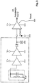
- Fig. 3 shows a schematic view of a block diagram of a possible arc detection, as is explained in more detail in the following publication.
- Arc sensors are known in the prior art. For example, go out of the WO 2014/032650 A1 a method and an apparatus for arc detection. This as well as the resulting block diagram can be used to provide an arc sensor accordingly. On the relevant content of this publication is in Scope of disclosure referred to.
- other arc sensors can also be used.
- arc detections that are arranged in the inverter. These are housed on a circuit board and allow the monitoring of solar cells there.
- Such boards can also be used for transmitting antenna systems in order to detect arcing faults, such as can occur, for example, in the case of damaged connecting terminals, corroded cables, worn insulation or other damage events in the area of the transmitting antenna system.
- arcing faults such as can occur, for example, in the case of damaged connecting terminals, corroded cables, worn insulation or other damage events in the area of the transmitting antenna system.
- noise by an arc generated there is the possibility that an arc is also detected in a different way.
- the monitoring has proven to be particularly advantageous in that the arc can be inferred on the basis of noise and thus the entire power path can also be monitored.
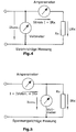
- Fig. 4 again shows a current-correct measurement in an exemplary circuit diagram
- Fig. 5 shows a voltage-correct measurement of the resistance. Both options are used in the first and in the second module, whereby from Fig. 6 an exemplary embodiment of the resistance measuring circuit for the first module emerges.
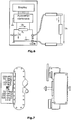
- Fig. 7 shows a schematic view of a stirrup connector, as has been discussed in more detail above, based on the patent application filed by the applicant.
- a housing for accommodating the resistance measuring device, the display electronics and also the internal arc sensor can be provided on this stirrup plug and on the devices there.
- a first LED chain can be provided, for example, which displays high-resistance measurement values, while a second LED chain displays low-resistance measurement values.
- the switch shown there it is possible to switch between a low-resistance and a high-resistance measurement.
- the transmitting antenna system to be monitored has at least one power transport path for supplying power to at least one first transmitting antenna and at least one resistance measuring device for determining an ohmic resistance for monitoring the transmitting antenna system.
- the resistance measuring device comprises at least one DC voltage source for applying a measurement DC voltage to at least the section of the power transport path. Furthermore, the resistance measuring device has at least one measuring device for determining the resistance of the section to which the DC measurement voltage is applied.
- the proposed monitoring can be used in a functional manner for transmission powers of up to 50 kW, preferably of preferably 2 kW to 50 kW.
- a measuring device for determining the resistance can be an ohmmeter, but it can also be additionally or alternatively provided, for example, that a measuring device is provided which provides for an indirect determination of a resistance.
- a redundancy measurement can be provided, for example for comparison and / or for cross-checking.
- an indirect determination can be provided by determining an electrical current and / or an electrical voltage.
- the resistance measuring device is arranged in an electrical feed line area of the power transport path.
- the feed line area of the power transport path denotes an area of the transmission antenna system, which is preferably designed as an RF cable or as an RF cable bundle, which leads to the first transmission antenna.
- the resistance measuring device is arranged on or in an HF cable or on or in a piping section of the power transport path.
- An advantage of arranging the resistance measuring device on or in an HF cable or on or in a piping section of the power transmission path is, for example, that the direct arrangement on the already existing infrastructure of the transmitting antenna system enables the resistance measuring device to be attached inexpensively while at the same time being efficient works and can be positioned flexibly.
- a resistance measuring device can be arranged such that it can be moved.
- Another embodiment provides, for example, that the resistance measuring device is not permanently installed. Rather, according to one embodiment, it can be arranged completely or at least partly only temporarily or arranged in the power transport path.
- a transportable checking device can be used to check the power transport path or to check the permanently installed monitoring of the power transport path in accordance with the system described here.
- the resistance measuring device is arranged at the start of a feed line.
- Arranging the resistance measuring device at the start of a feed line has the particular advantage of being able to enable complete monitoring of the infrastructure located beyond the start of the feed line against changes in resistance. In particular, this enables complete monitoring of the power transport path and the transmitting antenna against changes in resistance.
- the resistance measuring device is arranged in a switchgear panel that can be fitted at the start of the feed line.
- installing the resistance measuring device in a switchgear panel at the start of the feed line has the advantage that components that are already available and are intended to be inserted into the switch panel can be modified and used with the integrated resistance measuring device to such an extent that the existing infrastructure can otherwise be used largely unchanged .
- stirrup plug it can also be provided here, for example, that more than one stirrup plug are used in a parallel arrangement.
- the resistance measuring device is completely or partially installed in a stirrup plug which has at least one direct current feed element.
- the resistance measuring device has a direct current feed element.
- the power transport path of the transmitting antenna system which is provided for the transport of high-frequency power during operation, can be supplied with a direct current.
- the direct current feed element has a first contact element and a second contact element. It can further be provided that the first contact element and the second contact element are capacitively coupled, for example by means of at least one capacitor.
- the capacitive coupling means that the RF power to be transported can continue to pass between the transmitter and the power transport path, but the path for a direct current is blocked due to the capacitive coupling.
- a second connecting line leading to a third contact element is arranged starting from a first connecting line between the first contact element and the second contact element.
- the second connection line is starting from a side of the first connection line which faces the power transport path side of the capacitor. This creates a possibility of connecting the power transport path to one end of the second connecting line, whereas connecting one end of the second connecting line to the transmitter system via a direct current is prevented by the capacitive coupling of the first contact element.
- the second connecting line has at least one coupling element of the direct current feed element for connecting the second contact element to the third contact element.
- the coupling element is designed as a ⁇ / 4 stub line adaptation to the transmission antenna or as an L-C parallel resonant circuit.
- the coupling member is designed as a throttle.
- the advantage of introducing a coupling element which is designed as a ⁇ / 4 stub line adaptation, as an LC parallel resonant circuit or as a choke, is, among other things, a damping in the direction of the measuring device and / or the DC voltage source that occurs by means of destructive interference of the AC voltage leading to the power transport path so that they are separated from the AC components of the transmitter antenna system.
- the design of the coupling element with a bandwidth of a frequency range emitted by the transmitting antenna is carried out, for example, in such a way that that the coupling element filters a frequency approximately in the middle of the frequency range.
- a coupling element as a ⁇ / 4 stub line adaptation
- the second connecting line has a transition capacitor of the direct current feed element arranged between the coupling element and the third contact element.
- an RF-neutral space of the direct current feed element is arranged between the coupling element and the third contact element, which preferably has a gas discharge surge arrester.
- the resistance measuring device is connected to the system preferably has an interchangeable and / or pluggable built-in part which contains at least the direct current feed element.
- Embodiments are also possible in which the direct current feed element, the direct current source and / or the measuring device are arranged in a compact component.
- a connection to the first socket, the second socket and / or the third socket can be resolvable, which has the particular advantage that the resistance measuring device or components of the resistance measuring device are interchangeable.
- the direct current feed element is provided as a compact component and that the direct current feed element is present as an exchangeable built-in part.
- a connection of the third socket to the direct current source and / or the measuring device, or a connection of the third socket to the insulation measuring device is designed to be non-destructive, for example as a welded connection.
- a DC measurement voltage with a value between 48V and 500V can be provided.
- a DC measurement voltage with a value of 48V can preferably be provided. Different DC measuring voltages can also be used, which are preferably within the specified range.
- the transmitting antenna system is a radio antenna system.
- Another idea of the invention which can be used as a function of and independently of the transmission antenna system described above, relates to an installation part.
- an installation part can be provided, for example, whose first contact element and second contact element are capacitively coupled by means of at least one capacitor of the direct current feed element.
- it can be provided, for example, that starting from a first connecting line of the direct current supply element between the first contact element and the second contact element, preferably oriented on the power transport side of the capacitor, a second connecting line of the direct current supply element leading to the third contact element is arranged.
- a coupling member can be provided that is provided as part of the second connecting line.
- the coupling element is preferably designed as a ⁇ / 4 stub line adaptation to the transmission antenna and / or as an L-C parallel resonant circuit.
- the second connecting line has a transition capacitor arranged between the coupling element and the third contact element and that an HF-neutral one is provided between the transition capacitor and the third contact element Space of the DC supply element is arranged, which preferably has a surge arrester.
- the third contact element is a two-pole socket with a first pole and a second pole, one of the two poles being an earth pole.
- a resistance measuring device is arranged so that it can be replaced on the built-in part.
- Another idea of the invention which can be used depending on how independently of the transmission antenna system described above, relates to a method for monitoring an electrical line property of a transmission antenna system with a transmission power of at least 2 kW.
- the transmitting antenna system has at least one power transport path and at least one first transmitting antenna.
- At least a section of the power transport path is subjected to a DC measurement voltage and an ohmic resistance determination is carried out at least of the section of the power transport path.
- the ohmic resistance is determined as a function of time.
- an alarm signal is output when the resistance falls below a predetermined threshold, preferably when the resistance falls below between 100 kOhm and 500 kOhm, particularly preferably when the resistance falls below between 150 kOhm and 250 kOhm.
- the values mentioned here are low enough to avoid any false alarms due to a weather-related lowering of the resistance values, for example due to high air humidity and / or salty air.
- the ohmic resistance determination is preferably carried out with a controlled resistance determination in a continuous manner or at predetermined times.
- a transmission antenna system for the monitored operation of a telecommunications system with continuous or regularly recurring insulation measurement by providing at least a section of the power transmission path of the transmission antenna system with a DC measurement voltage and ohmic resistance determination of the section of the power transport path can be provided.
- provision can be made for measurements to be carried out at equidistant intervals. This does not necessarily require active regulation, but can be controlled according to a previously defined schedule.
- measurements take place at an interval of N hours between an i-th measurement and an (i + 1) -th measurement, where i is a positive natural number that is used as a running index.
- the number N can be a positive decimal number between 2 and 10, preferably between 4 and 8, particularly preferably between 5 and 7.
- the measurement result can be displayed directly on site.
- the measurement result is transmitted, for example via a bus system.
- a remote transmission can be provided, which enables monitoring far from the transmitter system.
- This can be a central monitoring center, for example, which is able to monitor a plurality of transmitter systems, transmitter masts and radio towers at different locations.
- Monitoring is preferably computer-controlled.
- a measurement can not only be monitored, but also triggered by a computer.
- the measurement results are preferably stored and can be evaluated automatically, for example statistically. For example, a repair can be triggered, especially a predictive check, before major damage can occur.
- a radio tower can have a plurality of such monitors distributed along the power transport path, preferably one behind the other at greater distances along the path. This not only enables the entire measurement of the power transport path, for example. Rather, it is possible to better locate one or more fault locations along the power transport path by means of the respective measurement. For example, a deviation can be detected by a comparison with a reference measurement. If the measurement begins with a monitoring device that is located closest to the transmitting antenna, but there are no or only slight deviations from the reference measurement, the measurement at the next monitoring device located further away from the transmitting antenna can then be used to determine whether has set a deviation outside of a tolerance. In this way, the test can continue to be carried out until a deviation is finally found outside of it Tolerance lies. This allows the location of the fault to be narrowed down, which makes work in a radio tower easier, for example.
- a transmission antenna system 1 'with a transmission power of at least 2 kW and with monitoring of an electrical line characteristic of the transmission antenna system 1' can be seen.
- the transmitting antenna system 1 ' has a first transmitting antenna 3', which runs over a power transport path 2 'is supplied with signals to be emitted via the first transmitting antenna 3'.
- the supply of the first transmitter antenna 3 'with the signals to be emitted takes place from a transmitter system 8'.
- the infrastructure of the first transmitter antenna 3' has a built-in part 4 'for monitoring an electrical line property of the transmitter system, which in the embodiment shown shows the Transmitting antenna system 1 'is arranged, for example, in the piping of the power transport path 2'.
- a resistance measuring device 5 'designed as an insulation measuring device is arranged on a third contact element 14' of the built-in part 4 '.
- the resistance measuring device 5 ' has a DC voltage source 6' and a resistance measuring device 7 '.
- four further cables can be seen, which run to further antennas, which in FIG Fig. 8 but are not shown.
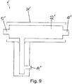
- FIG. 9 A configuration of an installation part 4 ′ with at least one coupling of a resistance measuring device into a power transport path of a transmitting antenna system with a transmitting power of at least 2 kW can be seen schematically.
- Fig. 9 a housing 21 'can be seen within which a direct current feed element (22') is arranged.
- the direct current feed element has a first contact element 12 'for coupling to the transmitter system, a second contact element 13' for coupling to the power transport path and a third contact element 14 '.
- the third contact element 14 ' is used to connect a DC voltage source and / or a measuring device for determining the resistance.
- a device combination is connected, which has a DC voltage source and / or a measuring device for determining the resistance.
- a commercially available insulation measuring device is connected to the third contact element 14 '.
- a DC voltage to act on the power transport path is fed into the power transport path via the direct current feed element 22 ′, which is located in the installation part 4 ′.
- FIG. 10 An embodiment of an installation part 4 'with at least one coupling of a resistance measuring device 5' into a power transport path 2 'can be found in a transmitting antenna system with a transmitting power of at least 2 kW.
- the built-in part 4 ' is designed as a compact part which is arranged entirely in a housing 21'.
- the installation part 4 ' comprises a direct current feed element, the design of which is shown in the circuit diagram shown within the housing 21'.
- the direct current feed element has a first contact element 12 'and a second contact element 13'.
- the first contact element 12 ' is provided for connecting the built-in part 4' to a transmission side, in the embodiment shown with a transmission system, the transmission antenna system.
- the transmitting side of the transmitting antenna system is connected to a power transport path 2' which is connected to the installation part at the second contact element 13 '.
- the power transport path 2 ' leads to at least one first transmission antenna 3' based on the contact made.
- the first connecting line 10 ' has an isolating capacitor 20', which capacitively couples the transmitter system and the power transport path to one another.
- the capacitive coupling ensures that the first connecting line is permeable to the alternating current that is used for the transport of the transmission signal.
- the first connecting line via the isolating capacitor 20 ' is largely blocked in relation to the transport of a direct current, so that, for example, the feeding of interference signals into the power transport path is avoided.
- a second connecting line 11 ' is arranged on the side of the separating capacitor 20' which faces the second contact element 13 '.
- the second connecting line 11 ' connects the section of the first connecting line 10' on the power transport side and the infrastructure connected to it via the second contact element 13 'with the third contact element 14'.
- the third contact element 14 ' is provided for the intended coupling of the resistance measuring device into the power transport path.
- a coupling element 9 ' is arranged, starting from the first connecting line 10' to the third contact element 14 'in the illustrated embodiment of the installation part 4' to the first one.
- the coupling member 9 ' is designed as a parallel arrangement of a capacitor and a coil.
- the coupling element 9 ' is connected to the third contact element 14' via a transition capacitor 15 '. Furthermore, an overvoltage arrester 19 'is formed in parallel to the third contact element 14' as part of the direct current feed element.
- the surge arrester is arranged within an HF-neutral space 16 '. In the embodiment shown, the surge arrester is designed as a gas discharge surge arrester.
- the gas discharge surge arrester is able to neutralize electromagnetic pulses, particularly those of natural origin, such as direct or indirect lightning strikes, and thereby keep them away from the connected devices.
- the neutralization of electromagnetic pulses from the connected devices is formed in a particularly efficient manner by the arrangement of the overvoltage lead 19 'within the HF-neutral space 16' and by the electrostatic separation from the other components of the direct current supply element by means of a transition capacitor 15 '.
- FIG. 11 A further embodiment of an installation part 4 'with at least one coupling of a resistance measuring device 5' into a power transport path 2 'can be found in a transmission antenna system.
- the transmitting antenna system has a transmitting power of at least 2 kW.
- Shown embodiment of the installation part 4 ' is that in the Fig. 11 Shown embodiment of a built-in part 4 'modified so that the connection of the second contact element 13' with the third contact element 14 'via a coupling member 9' which, in contrast to the configuration of the Fig. 11 is designed as a ⁇ / 4 stub.
- the ⁇ / 4 stub is based on the high-frequency resonance of the connected to the third contact element in the Fig. 11 adapted first transmission antenna 3 ', not shown, and the power transport path leading to it.
- the ⁇ / 4 stub is an empty line, by means of which the circuit is specifically provided with a reactance.
- an insulation measuring device is connected to the third contact element 14 ', which provides for the DC voltage to be simultaneously applied to the power transport path 2' and the ohmic resistance of the power transport to which the DC voltage is applied to be measured.
- a stationary insulation measuring device of type ST 2383 from Sourcetronic GmbH, Fahrenheitstrasse 1, D-28359 Bremen, with an adjustable measuring voltage between 10 V and 1000 V and an iso measuring range of 100 kOhm and 10 TOhm with an adjustable signal window can be used.
- An evaluation can be carried out via an acoustic signal with a binary output of a signal when the value falls below a previously defined and set limit.
- the measurement data can be controlled and / or evaluated via an RS 232 interface.
- the measuring cycle is adjustable.
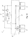
- FIG. 12 A further embodiment of an installation part 4 'with coupling in of at least one resistance measuring device 5' is Fig. 12 refer to.
- the design of the Fig. 12 is in its basic arrangement of the formation of the direct current feeder the design of an installation part of the Fig. 10 comparable.
- Fig. 12 On the design of the Fig. 10 in the design of the first contact element 12 'and the second contact element 13'.
- the first contact element 12 'and the second contact element 13' are in the Fig. 12 designed to be removed as sockets.
- the capacitor 10 ' is designed to improve the capacitive separation of the first contact element 12' and the second contact element 13 'as a ceramic plate.
- the ceramic plate shown for example, has a capacity of at least 500 microfarads.
- the in the Fig. 12 The embodiment shown corresponds in its design, for example, to a stirrup plug, as is used in many cases at the start of a feed line of a transmitting antenna system in which the resistance measuring device is integrated.
Description
Die vorliegende Erfindung betrifft eine Sendeantennenanlagen-Überwachungsvorrichtung mit einem Störlichtbogensensor. Des Weiteren wird eine Sendeantennenanlagen-Überwachungsvorrichtung mit mehreren Überwachungsmodulen zur jeweiligen Überwachung unterschiedlicher elektrischer Parameter der Sendeantennenanlage vorgeschlagen. Auch umfasst die Erfindung ein Verfahren zur Überwachung einer Sendeantennenanlage mittels zumindest eines Störlichtbogensensors.The present invention relates to a transmission antenna system monitoring device with an arcing sensor. Furthermore, a transmission antenna system monitoring device with several monitoring modules for the respective monitoring of different electrical parameters of the transmission antenna system is proposed. The invention also includes a method for monitoring a transmitting antenna system by means of at least one arc sensor.
In den Druckschriften
Weiterhin ist in der Druckschrift
Darüber hinaus ist in der Druckschrift
Schließlich ist in der Druckschrift
Sendeantennenanlagen der hier betroffenen Art sind UKW/DAB- und DVBT-Sendeantennenanlagen. Über diese werden Informationen auch in weit entfernt gelegene Gebiete übersendet. Dieses bedeutet, dass eine hochfrequente elektrische Leistung verwendet werden muss, um diese Signale über eine Sendeantenne versenden zu können, welche mit denen bei kleineren Sendeanlagen nicht vergleichbar ist. Hierfür sind Sendeleistungen im kW-Bereich notwendig. Die gattungsgemäßen Sendeantennenanlagen sind oftmals an Stahlgittermasten oder an geschlossenen Fernmeldetürmen in exponierten Positionen angeordnet. Diese unterliegen aufgrund der sehr langen Betriebszeit dieser Anlagen verschiedenen Einflüssen. Nicht ungewöhnlich sind Betriebszeiten von 30 Jahren und länger, so dass Effekte wie Korrosion, Materialermüdung, Schwitzwassereinlagerung oder andere Veränderungen eintreten können, welche die Betriebssicherheit der Sendeantennenanlagen beeinflussen und gegebenenfalls gefährden können.Transmitting antenna systems of the type concerned here are VHF / DAB and DVBT transmitting antenna systems. These are used to send information to areas far away. This means that high-frequency electrical power must be used in order to be able to send these signals via a transmitting antenna, which is not comparable with those in smaller transmitting systems. This requires transmission power in the kW range. The generic transmission antenna systems are often arranged on steel lattice masts or on closed telecommunication towers in exposed positions. Due to the very long operating time of these systems, these are subject to various influences. Operating times of 30 years and longer are not uncommon, so that effects such as corrosion, material fatigue, condensation water storage or other changes can occur which affect and possibly endanger the operational safety of the transmitter antenna systems.
Aufgabe der vorliegenden Erfindung ist es daher, die Betriebssicherheit von derart großen Sendeantennenanlagen permanent zu überwachen, um mögliche Emergency Situationen frühzeitig zu erkennen.The object of the present invention is therefore to permanently monitor the operational safety of such large transmitting antenna systems in order to identify possible emergency situations at an early stage.
Diese Aufgabe wird mit einer Sendeantennenanlagen-Überwachungsvorrichtung mit den Merkmalen des Anspruchs 1, mit einer weiteren Sendeantennenanlagen-Überwachungsvorrichtung mit den Merkmalen des Anspruchs 16 sowie mit einem Verfahren zur Überwachung einer Sendeantennenanlage mit den Merkmalen des Anspruchs 10 gelöst. Weitere vorteilhafte Ausgestaltungen und Weiterbildungen gehen aus den zugehörigen Unteransprüchen wie auch aus den nachfolgenden Beschreibungen, aber auch aus den einzelnen Figuren hervor. Es können ein oder mehrere Merkmale aus den jeweiligen unabhängigen Ansprüchen durch eines oder mehrere Merkmale aus den anderen Unteransprüchen, aus der Beschreibung wie auch unter Bezugnahme auf die Figuren ersetzt, ergänzt oder aber auch gestrichen werden. Weitere vorteilhafte Ausgestaltungen ergeben sich ebenfalls durch Kombinationen der verschiedenen offenbarten Merkmale, auch wenn diese in der Beschreibung so nicht explizit miteinander verknüpft wurden.This object is achieved with a transmission antenna system monitoring device with the features of claim 1, with a further transmission antenna system monitoring device with the features of
Insbesondere wird zur Lösung der Aufgabe eine Überwachungsvorrichtung für eine Sendeantennenanlage, die einen koaxialen Leistungstransportpfad, welche einen Innenleiter und einen Außenleiter aufweist, mit einer Messsignalabgreifleitung zum galvanischen Anschließen an den Innenleiter und einer Auswerte- und Ansteuereinheit mit einem mit der Messsignalabgreifleitung verbundenen Eingang und mit einem Ausgang, und einem Unterbrechungsschalter zum Unterbrechen der Sendesignal-Versorgung der Sendeantennenanlage vorgeschlagen, wobei der Unterbrechungsschalter mittels eines Ausgangssignals der Auswerte- und Ansteuereinheit ein- und ausschaltbar ist und wobei die Auswerteeinheit einem vorgegebenen niederfrequenten Frequenzbereich zwischen 0 Hz und 60 kHz, insbesondere in einem hörbaren Frequenzbereich zwischen 0 Hz und 20 kHz, 0 Hz und 19 kHz, 0 Hz und 15 kHz, 0 Hz und 5 kHz oder 0 Hz und 4 kHz mit einem Schwellwert vergleicht und dann, wenn der Messwert in dem besagten Frequenzbereich größer ist als der Schwellwert, an ihrem Ausgang ein Ausschaltsignal zum zumindest zeitweisen Ausschalten des Unterbrechungsschalters ausgibt.In particular, the solution to the problem is a monitoring device for a transmitting antenna system, which has a coaxial power transport path, which has an inner conductor and an outer conductor, with a measurement signal tapping line for electrical connection to the inner conductor and an evaluation and control unit with an input connected to the measurement signal tapping line and with one Output, and an interruption switch for interrupting the transmission signal supply to the transmission antenna system, the interruption switch being able to be switched on and off by means of an output signal from the evaluation and control unit, and the evaluation unit having a predetermined low-frequency range between 0 Hz and 60 kHz, in particular in an audible range Frequency range between 0 Hz and 20 kHz, 0 Hz and 19 kHz, 0 Hz and 15 kHz, 0 Hz and 5 kHz or 0 Hz and 4 kHz with compares a threshold value and, if the measured value in the said frequency range is greater than the threshold value, outputs a switch-off signal at its output for at least temporarily switching off the interruption switch.
Dabei weist die Auswerte- und Ansteuereinheit einen Lichtbogen- bzw. Störlichtbogendetektor auf. Dieser Detektor wertet das Messsignal in einem vorgebbaren, bevorzugten Frequenzbereich aus. Dabei ist es von Vorteil, die Auswertung auf die genannten Frequenzbereiche zu beschränken, da in diesen Frequenzbereichen das Störlichtbogensignal besonders gut zu detektieren ist. Außerdem sind die genannten Frequenzbereiche ausreichend weit von dem Frequenzbereich entfernt, in dem das Nutzsignal gesendet wird. Dadurch wird gewährleistet, dass es zu keiner signifikanten Überlagerung von Nutz- und Störsignal kommen kann. Hierdurch kann das zu detektierende Störsignal besonders gut detektiert werden, da es vom Nutzsignal separiert ist.The evaluation and control unit has an arc or arcing detector. This detector evaluates the measurement signal in a predeterminable, preferred frequency range. It is advantageous to limit the evaluation to the frequency ranges mentioned, since the arcing signal can be detected particularly well in these frequency ranges. In addition, the frequency ranges mentioned are sufficiently far from the frequency range in which the useful signal is transmitted. This ensures that there is no significant overlay of useful and interference signals. As a result, the interference signal to be detected can be detected particularly well since it is separated from the useful signal.
Darüber hinaus wird durch den direkten, galvanischen Abgriff des Signals am Innenleiter ein niederohmiger Abgriff des Signals ermöglicht. Dadurch kann die Auswerte- und Ansteuereinheit mit einem deutlich stärkeren Signal versorgt werden, als dies der Fall wäre, wenn etwa der Abgriff induktiv erfolgen würde.In addition, the direct, galvanic tapping of the signal on the inner conductor enables a low-resistance tapping of the signal. As a result, the evaluation and control unit can be supplied with a significantly stronger signal than would be the case if the tap were made inductively.
Bei einer Ausführungsform der Erfindung kann vorgesehen sein, dass der mit dem Schwellwert verglichene Messwert einen Intensitätswert des Messsignals darstellt. Hierbei kann beispielsweise ein Intensitätswert, der bei einer einzelnen Frequenz gemessen wird, mit dem vorgebbaren Schwellwert verglichen werden. Dieser Intensitätswert kann beispielsweise bei 60 kHz, bei 20 kHz oder bei 19 kHz gemessen werden.In one embodiment of the invention it can be provided that the measured value compared with the threshold value represents an intensity value of the measurement signal. Here, for example, an intensity value that is measured at a single frequency can be compared with the predefinable threshold value. This intensity value can be measured, for example, at 60 kHz, at 20 kHz or at 19 kHz.
Bei einer weiteren Ausführungsform kann vorgesehen sein, dass der Messwert aus einer Messung in einem vorgegebenen Frequenzbereich ermittelt wird. Dabei ist es möglich, beispielsweise den arithmetischen Mittelwert des Messsignals in einem Frequenzbereich von 0 Hz bis 60 kHz oder von 0 Hz bis 20 kHz (oder einem der zuvor genannten Frequenzbereiche), als Messwert zu verwenden, der mit einem Schwellwert verglichen wird. Auch ist es möglich, den arithmetischen Mittelwert des Betrages des Messsignals in einem der zuvor genannten Frequenzbereiche als Messwert zu verwenden. Weiterhin kann auch die Varianz oder die Standardabweichung des Messsignals in einem vorgebbaren Frequenzbereich als Messwert verwendet werden.In a further embodiment it can be provided that the measured value is determined from a measurement in a predetermined frequency range. It is possible, for example, to add the arithmetic mean of the measurement signal in a frequency range from 0 Hz to 60 kHz or from 0 Hz to 20 kHz (or one of the previously mentioned frequency ranges) use that is compared to a threshold value. It is also possible to use the arithmetic mean of the amount of the measurement signal in one of the previously mentioned frequency ranges as the measurement value. Furthermore, the variance or the standard deviation of the measurement signal in a predeterminable frequency range can also be used as the measurement value.
Bei einer bevorzugten Ausführung der Erfindung kann weiterhin vorgesehen sein, dass die Auswerte- und Ansteuereinheit nach einem Ausschaltsignal automatisch ein Einschaltsignal für den Unterbrechungsschalter ausgibt und überprüft, ob der Messwert in dem besagten Frequenzbereich größer ist als der Schwellwert, woraufhin, wenn dies der Fall ist, die Auswerte- und Ansteuereinheit wieder ein Ausschaltsignal zum Ausschalten des Unterbrechungsschalters ausgibt.In a preferred embodiment of the invention, it can further be provided that the evaluation and control unit automatically outputs a switch-on signal for the interruption switch after a switch-off signal and checks whether the measured value in the said frequency range is greater than the threshold value, whereupon if this is the case , the evaluation and control unit again outputs a switch-off signal for switching off the interruption switch.
Durch das mehrmalige Ein- und Ausschalten des Unterbrechungsschalters kann überprüft werden, ob es sich bei der detektieren Störung um eine kurzzeitige Störung handelt, oder ob diese Störung dauerhaft vorliegt. Häufig verschwindet eine Störung bereits nach dem Ausschalten und dem Wiedereinschalten der Sendeantennenanlage. In diesem Fall kann die Störung dann meist ignoriert werden. Ist die Störung jedoch von längerer Dauer und nicht durch ein einfaches Aus- und Einschalten behebbar, so kann die Sendeantennenanlage im Anschluss dauerhaft ausgeschaltet werden, bis das Problem etwa durch einen Service-Techniker behoben wurde.By repeatedly switching the interruption switch on and off, it can be checked whether the detected fault is a short-term fault or whether this fault is permanent. A malfunction often disappears after the transmitter antenna system has been switched off and on again. In this case, the fault can usually be ignored. However, if the fault is longer and cannot be remedied by simply switching it off and on, the transmitter antenna system can then be switched off permanently until the problem has been rectified by a service technician, for example.
In einer Ausgestaltung der Erfindung kann vorgesehen sein, dass die Auswerte- und Ansteuereinheit wechselweise Einschalt- und Ausschaltsignale für den Unterbrechungsschalter aussendet, und zwar solange, bis der Messwert in dem besagten Frequenzbereich größer ist als der Schwellwert, wobei nach einer vorgegebenen Anzahl von Wiederholungen der wechselweisen Ausgabe von Einschalt- und Ausschaltsignalen der Unterbrechungsschalter ausgeschaltet bleibt.In one embodiment of the invention, it can be provided that the evaluation and control unit alternately sends switch-on and switch-off signals for the interruption switch until the measured value in the said frequency range is greater than the threshold value, after a predetermined number of repetitions of the alternate output of switch-on and switch-off signals the circuit breaker remains switched off.
Auf diese Weise kann überprüft werden, ob die Störung durch ein mehrmaliges Aus- und Einschalten der Sendeantennenanlage behoben werden kann. Dabei kann vorgegeben sein, wie häufig die Sendeantennenanlage aus- und eingeschaltet werden soll, bevor die Sendeantennenanlage endgültig abgeschaltet werden soll. Beispielsweise kann hierbei vorgegeben sein, dass die Sendeantennenanlage insgesamt drei Mal aus- und eingeschaltet wird, bis sie dann endgültig ausgeschaltet wird, sofern das Störsignal immer noch vorhanden ist.In this way, it can be checked whether the fault can be remedied by switching the transmitting antenna system off and on several times. It can be specified how often the transmitting antenna system should be switched off and on before the transmitting antenna system is to be finally switched off. For example, it can be specified here that the transmitting antenna system is switched off and on a total of three times until it is finally switched off if the interference signal is still present.
In einer bevorzugten Ausgestaltung der Erfindung kann vorgesehen sein, dass die Messsignalabgreifleitung eine λ/4-Leitung ist, wobei λ die Wellenlänge der Trägerfrequenz des Sendesignals der Sendeantennenanlage ist.In a preferred embodiment of the invention it can be provided that the measurement signal tapping line is a λ / 4 line, where λ is the wavelength of the carrier frequency of the transmission signal of the transmission antenna system.
Weiterhin kann in einer Ausführungsform der Erfindung vorgesehen sein, dass für eine Sendeantennenanlage mit einer galvanisch offenen Antenne die Auswerte- und Ansteuereinheit über die Messsignalabgreifleitung einen Messstrom in den Innenleiter einprägt und den Widerstand zwischen Außenleiter und Innenleiter des Leistungspfads misst und, wenn der gemessene Widerstand kleiner ist als ein vorgebbarer Minimalwiderstand, an ihrem Ausgang ein Ausschaltsignal für den Unterbrechungsschalter ausgibt und/oder an ihrem Ausgang ein Anzeigesignal zur optischen Anzeige des gemessenen Widerstands oder eines diesen charakterisierenden Werts ausgibt.Furthermore, it can be provided in one embodiment of the invention that for a transmitting antenna system with a galvanically open antenna, the evaluation and control unit impresses a measuring current into the inner conductor via the measuring signal tapping line and measures the resistance between the outer conductor and the inner conductor of the power path and, if the measured resistance is less is a predefinable minimum resistance, outputs a switch-off signal for the interruption switch at its output and / or outputs a display signal at its output for the optical display of the measured resistance or a value characterizing it.
Bei dieser Messung handelt es sich um einen Isolationswiderstandsmessung. Durch die Isolationswiderstandmessung kann eine Fehlfunktion oder ein Mangel der Antennenanlage bereits frühzeitig erkannt werden. Fällt der gemessene Widerstand unter einen vorgebbaren Schwellwert, so wird die Sendeantennenanlage ausgeschaltet und/oder eine Warnung ausgeben. Der Isolationswiderstand kann beispielsweise dadurch herabsinken, dass Feuchtigkeit oder Nässe in die Antennenanlage eindringt und dies eine Erhöhung der Leitfähigkeit von konstruktiv notwendigen Isolationsbauteilen bewirkt. Infolgedessen ist die Gefahr eines Kurzschlusses und einer Beschädigung oder sogar Zerstörung der Antennenanlage gegeben.This measurement is an insulation resistance measurement. A malfunction or a deficiency in the antenna system can be detected early by measuring the insulation resistance. If the measured resistance falls below a predefinable threshold value, the transmitting antenna system is switched off and / or a warning is issued. The insulation resistance can decrease, for example, by the fact that moisture or wetness penetrates into the antenna system and this causes an increase in the conductivity of insulation components that are required for the design. As a result, there is a risk of a short circuit and damage or even destruction of the antenna system.
Die Warnung bei einer detektierten Fehlfunktion kann durch ein optisches Signal erfolgen. Dabei können beispielsweise LEDs kettenförmig nebeneinander angeordnet sein, wobei das Aufleuchten jeder einzelnen LED anzeigen kann, in welchem Widerstandsbereich sich der gemessene Widerstandswert befindet.The warning in the event of a detected malfunction can be given by an optical signal. In this case, for example, LEDs can be arranged side by side in a chain, the lighting up of each individual LED being able to indicate the resistance range in which the measured resistance value is located.
Darüber hinaus kann in einer Ausführungsform der Erfindung vorgesehen sein, dass für eine Sendeantennenanlage mit einer galvanisch geschlossenen Antenne die Auswerte- und Ansteuereinheit über die Messsignalabgreifleitung eine Messung des Widerstands des elektrischen Kreises aus Innenleiter, Außenleiter und Antenne durchführt und, wenn der gemessene Widerstand größer ist als ein vorgebbarer zulässiger Maximalwiderstand, an ihrem Ausgang ein Ausschaltsignal für den Unterbrechungsschalter ausgibt, und/oder ein Anzeigesignal zur optischen Anzeige des gemessenen Widerstands oder eines diesen charakterisierenden Werts ausgibt.In addition, it can be provided in one embodiment of the invention that, for a transmitting antenna system with a galvanically closed antenna, the evaluation and control unit carries out a measurement of the resistance of the electrical circuit comprising the inner conductor, outer conductor and antenna via the measurement signal tapping line, and if the measured resistance is greater as a predeterminable permissible maximum resistance, outputs a switch-off signal for the interruption switch at its output, and / or outputs a display signal for the optical display of the measured resistance or a value characterizing it.
Auf diese Weise können Mängel, die in einer Komponente der Antennenanlage auftreten, detektiert werden. In einem ordnungsgemäßen Zustand der Antennenanlage beträgt der beschriebene Widerstand, der auch als Schleifenwiderstand bezeichnet wird, typischerweise nur einige 10 mΩ bis einige 100 mΩ. Wird ein größerer Widerstand gemessen, beispielsweise ein Widerstand, der größer oder gleich 1 Ω ist, so kann davon ausgegangen werden, dass mindestens eine Komponente der Antennenanlage einen Mangel aufweist. Dieser Mangel kann insbesondere durch Alterungserscheinungen wie beispielsweise Korrosion einzelner Antennenkomponenten entstehen.In this way, defects that occur in a component of the antenna system can be detected. When the antenna system is in a proper state, the resistance described, which is also referred to as a loop resistance, is typically only a few 10 mΩ to a few 100 mΩ. If a greater resistance is measured, for example a resistance that is greater than or equal to 1 Ω, it can be assumed that at least one component of the antenna system is defective. This deficiency can arise in particular from signs of aging such as corrosion of individual antenna components.
Bei einer permanenten, oder auch nur zeitweisen Beaufschlagung eines zu überwachenden Antennensystems mit einer Gleichspannung (d.h. es fließt permanent oder auch nur zeitweise ein auch nur geringer Gleichstrom immer in die gleiche elektrische Richtung) kann es zu einer Ionenwanderung mit der Folge einer Materialverfrachtung kommen. Um dies zu unterbinden, muss die zu Messzwecken eingespeiste Gleichspannung mit einer (wenn auch) sehr niedrigen Frequenz umgetastet werden.If the antenna system to be monitored is permanently or even temporarily exposed to a DC voltage (i.e. permanent or even only a small amount of DC current always flows in the same electrical direction), ion migration can occur, resulting in material being shipped. In order to prevent this, the DC voltage fed in for measurement purposes must be re-keyed with a (albeit) very low frequency.
Weiterhin kann bei einer Ausführungsform der Erfindung vorgesehen sein, dass die Messsignalabgreifleitung an den Innenleiter eines Brückensteckers der Sendeantennenanlage galvanisch anschließbar ist.Furthermore, it can be provided in one embodiment of the invention that the measurement signal tapping line can be connected galvanically to the inner conductor of a bridge connector of the transmitting antenna system.
Weiterhin wird zur Lösung der zuvor genannten Aufgabe ein Verfahren zur Überwachung einer Sendeantennenanlage, die einen Leistungstransportpfad mit einem Innenleiter und einem Außenleiter aufweist, vorgeschlagen, wobei bei dem Verfahren von dem Innenleiter über eine mit diesem galvanisch verbundenen Messsignalabgreifleitung ein Messsignal abgegriffen wird, und ein Messwert des Messsignals in einem vorgebbaren Frequenzbereich zwischen 0 und 60 kHz, insbesondere zwischen 0 und 20 kHz, mit einem Schwellwert verglichen wird und dann, wenn der Messwert in dem besagten Frequenzbereich größer ist als der Schwellwert, die Zufuhr eines Sendesignals zur Sendeantennenanlage zumindest zeitweise unterbrochen wird.Furthermore, a method for monitoring a transmitting antenna system, which has a power transport path with an inner conductor and an outer conductor, is proposed to achieve the aforementioned object, wherein in the method a measuring signal is tapped from the inner conductor via a measuring signal tapping line that is electrically connected to the latter, and a measured value of the measurement signal in a predeterminable frequency range between 0 and 60 kHz, in particular between 0 and 20 kHz, is compared with a threshold value and, if the measurement value in the said frequency range is greater than the threshold value, the supply of a transmission signal to the transmission antenna system is at least temporarily interrupted .
In einer bevorzugten Ausführungsform des erfindungsgemäßen Verfahrens kann vorgesehen sein, dass als Messsignalabgreifleitung eine λ/4-Leitung verwendet wird, wobei λ die Wellenlänge der Trägerfrequenz des Sendesignals der Sendeantennenanlage ist.In a preferred embodiment of the method according to the invention, it can be provided that a λ / 4 line is used as the measurement signal tapping line, where λ is the wavelength of the carrier frequency of the transmission signal of the transmission antenna system.
In einer weiteren Ausgestaltung des erfindungsgemäßen Verfahrens kann vorgesehen sein, dass für eine Sendeantennenanlage mit einer galvanisch offenen Antenne über die Messsignalabgreifleitung ein Messstrom in den Innenleiter einprägt wird und der Widerstand zwischen Außenleiter und Innenleiter des Leistungspfads gemessen wird und, wenn der gemessene Widerstand kleiner ist als ein vorgebbarer Minimalwiderstand, die Zufuhr des Sendesignals zur Sendeantennenanlage zumindest zeitweise unterbrochen wird und/oder ein Anzeigesignal zur optischen Anzeige des gemessenen Widerstands oder eines diesen charakterisierenden Werts ausgegeben wird.In a further embodiment of the method according to the invention, it can be provided that for a transmission antenna system with a galvanically open antenna, a measurement current is impressed into the inner conductor via the measurement signal tapping line and the resistance between the outer conductor and the inner conductor of the power path is measured and if the measured resistance is less than a predeterminable minimum resistance, the supply of the transmission signal to the transmission antenna system is interrupted at least temporarily and / or a display signal for the optical display of the measured resistance or a value characterizing it is output.
Weiterhin kann in einer Ausgestaltung der Erfindung vorgesehen sein, dass für eine Sendeantennenanlage mit einer galvanisch geschlossenen Antenne über die Messsignalabgreifleitung eine Messung des Widerstands des elektrischen Kreises aus Innenleiter, Außenleiter und Antenne durchgeführt wird und, wenn der gemessene Widerstand größer ist als ein vorgebbarer zulässiger Maximalwiderstand, an ihrem Ausgang ein Ausschaltsignal für den Unterbrechungsschalter ausgegeben wird, und/oder ein Anzeigesignal zur optischen Anzeige des gemessenen Widerstands oder eines diesen charakterisierenden Werts ausgegeben wird.Furthermore, it can be provided in one embodiment of the invention that for a transmitting antenna system with a galvanically closed antenna the measurement signal tapping line carries out a measurement of the resistance of the electrical circuit comprising the inner conductor, outer conductor and antenna and, if the measured resistance is greater than a predeterminable permissible maximum resistance, a switch-off signal for the interruption switch is output at its output and / or a display signal for visual display of the measured resistance or a value characterizing this.
Auch kann in einer Ausgestaltung des erfindungsgemäßen Verfahrens vorgesehen sein, dass die Messsignalabgreifleitung an den Innenleiter eines Brückensteckers der Sendeantennenanlage galvanisch angeschlossen wird.It can also be provided in one embodiment of the method according to the invention that the measurement signal tapping line is electrically connected to the inner conductor of a bridge connector of the transmitting antenna system.
Weiterhin wird zur Lösung der vorstehend genannten Aufgabe eine Sendeantennenanlage mit einem Leistungstransportpfad mit einem Innenleiter und einem Außenleiter und mit einer Überwachungsvorrichtung mit den zuvor genannten Merkmalen und/oder einem Verfahren mit den zuvor genannten Merkmalen vorgeschlagen.Furthermore, a transmission antenna system with a power transport path with an inner conductor and an outer conductor and with a monitoring device with the aforementioned features and / or a method with the aforementioned features is proposed to achieve the above-mentioned object.
Darüber hinaus wird eine Sendeantennenanlagen-Überwachungsvorrichtung mit einem Störlichtbogensensor, der einen Rauschanteil eines Frequenzbereichs überwacht, vorgeschlagen. Die Sendeantennenanlagen-Überwachungsvorrichtung weist einen Unterbrecher auf, der eine Trägerschleife der Sendeantennenanlage unterbricht. Im Folgenden wird dieser Unterbrecher auch als Unterbrechungsschalter bezeichnet. Des Weiteren ist eine Steuerung vorgesehen, die in Verbindung mit dem Unterbrecher steht und den Unterbrecher in Abhängigkeit von einem aufgenommenen Rauchsignal auslöst, wobei die Steuerung in Abhängigkeit vom Rauschsignal auswählt zwischen zumindest einer kurzzeitigen Unterbrechung und einer dauerhaften Unterbrechung der Trägerschleife.In addition, a transmission antenna system monitoring device with an arcing sensor that monitors a noise component of a frequency range is proposed. The transmitting antenna system monitoring device has an interrupter which interrupts a carrier loop of the transmitting antenna system. In the following, this interrupter is also referred to as an interruption switch. Furthermore, a controller is provided which is connected to the interrupter and triggers the interrupter as a function of a recorded smoke signal, the controller selecting between at least a brief interruption and a permanent interruption of the carrier loop as a function of the noise signal.
Bevorzugt sind der Störlichtbogensensor, der Unterbrecher wie auch die Steuerung auf einer Trägerplatine gemeinsam angeordnet. Dieses erlaubt beispielsweise, dass der Störlichtbogensensor als ein einzelnes Bauteil beispielsweise in einem eigenen Gehäuse an die Sendeantennenanlage angeschlossen werden kann.The arcing fault sensor, the interrupter and also the controller are preferably arranged together on a carrier board. This allows, for example, the arcing sensor to be used as a single component, for example can be connected to the transmitter antenna system in its own housing.
Gemäß einer Ausgestaltung ist beispielsweise vorgesehen, dass eine Lichtbogenerkennungsplatine in einem Anbaugehäuse untergebracht ist. Dieses wird beispielsweise direkt mit einem Brückenstecker verbunden. Ein Brückenstecker geht beispielsweise aus der
Eine Weiterbildung sieht vor, dass die Überprüfung mittels des Störlichtbogensensors permanent erfolgt. Dieses hat den Vorteil, dass auch kurzzeitig auftretendes Rauschen direkt detektiert werden kann und im Rahmen einer Steuerung, ggf. Regelung, dahingehend untersucht werden kann, ob es sich um einen Hinweis auf einen entstandenen Lichtbogen handelt oder aber um ein Rauschen, was beispielsweise durch atmosphärische Störungen in dem Leistungspfad erzeugt worden ist. Der Lichtbogensensor ist dadurch in der Lage, selbst kleinste Funkenbildungen, welche durch Kontakt oder Isolationsprobleme hervorgerufen werden könnten, zu detektieren.A further development provides that the check by means of the arc sensor is carried out permanently. This has the advantage that even briefly occurring noise can be detected directly and can be examined in the context of a control, possibly regulation, to determine whether it is an indication of an arc that has arisen or whether it is noise, for example due to atmospheric Disturbances in the power path has been generated. As a result, the arc sensor is able to detect even the smallest spark formation, which could be caused by contact or insulation problems.
Gemäß einer Ausgestaltung ist vorgesehen, dass der Störlichtbogensensor vorzugsweise einen vorgegebenen Frequenzbereich überwacht. Besonders bevorzugt ist es, wenn dieser vorgebbare Frequenzbereich sich auch ändern lässt. Gemäß einer weiteren Ausgestaltung ist beispielsweise vorgesehen, dass verschiedene Frequenzbereiche überwacht werden. Dieses kann beispielsweise durch eine Vielzahl an jeweils einem Frequenzbereich zugeordneten Störlichtbogensensoren erfolgen. Eine andere Ausgestaltung sieht wiederum vor, dass mehrere Frequenzbereiche einem Störlichtbogensensor zugeordnet sind. Durch ein Springen zwischen diesen verschiedenen Frequenzbereichen und jeweiligem Abtasten derselben kann ebenfalls ein Rauschzustand detektiert werden, der einen Hinweis auf einen Fehler ermöglicht.According to one embodiment, it is provided that the arc sensor preferably monitors a predetermined frequency range. It is particularly preferred if this predeterminable frequency range can also be changed. According to a further embodiment, it is provided, for example, that different frequency ranges are monitored. This can, for example by a large number of arcing sensors assigned to a frequency range. Another embodiment in turn provides that a plurality of frequency ranges are assigned to an arcing fault sensor. By jumping between these different frequency ranges and scanning them in each case, a noise state can also be detected, which enables an indication of an error.
Eine Ausgestaltung sieht vor, dass der Störlichtbogensensor stetig den RF-Transportpfad auf Rauschanteile in einem Bereich um 450 kHz erfasst. Detektiert nun der Lichtbogensensor einen abnormalen Rauschanteil im 450-kHz-Fenster, so ist beispielsweise vorgesehen, dass für einen kurzen Zeitraum diese Rauschglocke hinsichtlich ihres Andauerns überwacht wird. Dauert diese Rauschglocke länger an, beispielsweise 3 oder mehr Sekunden, kann vorgesehen sein, dass der Unterbrecher die zugehörige Trägerschleife unterbricht. Dadurch wird die Sendeleistung aller auf dieser Antenne geführten Sender kurzzeitig unterbrochen. Im Anschluss daran wird sofort jedoch wieder die Unterbrechung aufgehoben und die Trägerschleife geschlossen. Sind nach dem kurzzeitigen Ausschalten des oder der Sender die Rauschanteile verschwunden, kann beispielsweise vorgesehen sein, dass hierzu eine Protokollierung erfolgt, die sodann im Rahmen beispielsweise einer regelmäßigen Wartung der Sendeantennenanlage herangezogen wird.One embodiment provides that the arcing fault sensor continuously detects the RF transport path for noise components in a range around 450 kHz. If the arc sensor now detects an abnormal noise component in the 450 kHz window, it is provided, for example, that this noise bell is monitored for its duration for a short period of time. If this noise bell lasts longer, for example 3 or more seconds, it can be provided that the interrupter interrupts the associated carrier loop. As a result, the transmission power of all transmitters on this antenna is briefly interrupted. Afterwards, however, the interruption is immediately canceled and the carrier loop is closed. If, after the transmitter or the transmitter has been briefly switched off, the noise components have disappeared, it can be provided, for example, that logging is carried out for this purpose, which is then used as part of regular maintenance of the transmitter antenna system, for example.
Ist jedoch die kurzzeitige Unterbrechung der Trägerschleife nicht ausreichend und die Rauschanteile bzw. die Rauschglocke entsteht hingegen wieder sofort, kann beispielsweise gemäß einer Ausgestaltung vorgesehen sein, dass sodann die Trägerschleife dauerhaft unterbrochen wird. Eine Ausgestaltung sieht beispielsweise vor, dass mehrfach getestet wird, ob die Rauschglocke wieder sofort nach Öffnen und Schließen der Trägerschleife entsteht. So kann z.B. eine mehrmalige Unterbrechung und Schließung der Trägerschleife vorgesehen sein, wobei nach Erreichen einer einstellbaren Anzahl an Unterbrechungen und Schließungen schließlich nicht mehr eine kurzzeitige, sondern eine dauerhafte Unterbrechung der Trägerschleife erfolgt.If, however, the brief interruption of the carrier loop is not sufficient and the noise components or the noise bell, on the other hand, arise again immediately, it can be provided, for example, according to one embodiment that the carrier loop is then permanently interrupted. One embodiment provides, for example, that multiple tests are carried out to determine whether the noise bell is produced again immediately after the carrier loop is opened and closed. For example, a repeated interruption and closing of the carrier loop can be provided, whereby after reaching an adjustable number of interruptions and closings, the carrier loop is no longer briefly interrupted but permanently.
Gemäß einer Ausgestaltung ist beispielsweise vorgesehen, dass sich dieses dreimal in Folge wiederholt, bevor die Trägerschleife dauerhaft geöffnet verbleibt. Bevorzugt ist, dass die dauerhafte Unterbrechung der Trägerschleife nicht durch den Lichtbogensensor bzw. die zugehörige Steuerung selbst wieder aufgehoben werden kann. Vielmehr ist bevorzugt vorgesehen, dass dazu eine andere Betätigung zur Aufhebung der Unterbrechung notwendig wird. Insbesondere ist vorgesehen, dass dieses nur durch ein händisches Zurückstellen vor Ort erfolgen kann.According to one embodiment, it is provided, for example, that this is repeated three times in succession before the carrier loop remains permanently open. It is preferred that the permanent interruption of the carrier loop cannot be canceled again by the arc sensor or the associated control itself. Rather, it is preferably provided that another actuation is required to cancel the interruption. In particular, it is provided that this can only be done by manual resetting on site.
Hintergrund ist, dass bei einer Vielzahl an wieder auftretendem Entstehen von Rauschen ein tatsächlicher Fehler in der Trägerschleife und vor allem auch eine Lichtbogenentstehung anzunehmen ist. Diese zusätzliche Sicherung verhindert, dass die Sendeantennenanlage größeren Schädigungen unterworfen wird, wie sie beispielsweise durch Brände ausgelöst werden könnten. Der Vorteil dieser zusätzlichen Sicherung in Form eines händischen Resets vor Ort stellt sicher, dass die Anlage erst dann wieder in Betrieb genommen wird, wenn überprüft wurde, an welcher Stelle denn der Lichtbogen überhaupt entstanden ist und eine entsprechende Reparatur ausgeführt wurde.The background to this is that with a large number of recurring noises, an actual fault in the carrier loop and, above all, an arcing can be assumed. This additional safeguard prevents the transmitter antenna system from being subjected to major damage, such as could be caused by fires, for example. The advantage of this additional fuse in the form of a manual reset on site ensures that the system is only put back into operation when it has been checked at which point the arc was created and a corresponding repair was carried out.
Andere Sicherungsmöglichkeiten können ebenfalls genutzt werden. Ebenfalls ist es möglich, dass die Wiederinbetriebnahme auch durch andere Aktivierungsmöglichkeiten erfolgen kann. Beispiel kann vorgesehen sein, dass erst ein händisches Freischalten notwendig ist, bevor beispielsweise von einer Fernwarte die Wiederinbetriebnahme ausgelöst werden kann. Auch besteht die Möglichkeit, dass bei einer Anordnung von mehreren Lichtbogensensoren eine Freischaltung ggf. von denjenigen Trägerschleifen ermöglicht wird, die eventuell nicht von einer Lichtbogenbildung betroffen sind. Dieses ist beispielsweise möglich, wenn beispielsweise eine Detektierung desjenigen Abschnittes vorliegt, in dem der Lichtbogen entstanden ist. Eine Detektierung kann beispielsweise durch verschiedene Messmittel an verschiedenen Orten der Trägerschleife erfolgen.Other backup options can also be used. It is also possible that the restart can also be carried out using other activation options. For example, provision can be made that manual activation is necessary before the restart can be triggered, for example, by a remote control room. There is also the possibility that with an arrangement of several arc sensors, it may be possible to enable those carrier loops that may not be affected by arcing. This is possible, for example, if there is a detection of the section in which the arc has arisen. Detection can take place, for example, using different measuring devices at different locations on the carrier loop.
Gemäß einer weiteren Ausgestaltung der Erfindung, die auch unabhängig von der obigen Sendeantennenanlagen-Überwachungsvorrichtung wie auch mit derselben genutzt werden kann, ist eine Sendeantennenanlagen-Überwachungsvorrichtung mit mehreren Überwachungsmodulen zur jeweiligen Überwachung unterschiedlicher elektrischer Parameter der Sendeantennenanlage. Diese Sendeantennenanlagen-Überwachungsvorrichtung ist bevorzugt mit einem ersten Modul mit einer Isolationswiderstandsmessung zur Überwachung einer galvanisch offenen Antennenkonstruktion über eine Gleichstrom-Einspeise-Weiche der Sendeantennenanlage, mit einem zweiten Modul mit einer niederohmigen Schleifenmessung eines Widerstands eines Innenleiters in einem Leistungstransportpfad, und mit einem dritten Modul, das einen Störlichtbogensensor aufweist, vorzugsweise einen Störlichtbogensensor, wie oben beschrieben, versehen. Das erste Modul weist vorzugsweise eine hochohmige Isolationsmessung auf, wie sie beispielsweise aus der oben schon genannten
Die Isolationswiderstandsmessung erfolgt vorzugsweise permanent, wobei der Isolationswiderstand von galvanisch offenen Antennenkonstruktionen über eine Gleichstrom-Einspeise-Weiche überwacht wird. Diese Gleichstrom-Einspeise-Weiche geht aus der oben genannten Druckschrift näher hervor. Der Widerstand wird durch eine gleichzeitig erfolgte Strom- und Spannungsmessung ermittelt. Hierfür wird eine stromrichtige Messschaltung genutzt. Die Messergebnisse werden in einem Elektronikbaustein aufbereitet, in einem Anzeigebaustein dekodiert und mittels einer LED-Kette zur Anzeige gebracht. Eine externe Konstantstromquelle versorgt diese Messeinrichtung mit einer Betriebsspannung.The insulation resistance measurement is preferably carried out permanently, the insulation resistance of galvanically open antenna constructions being monitored via a direct current feed switch. This DC feed-in switch emerges from the above-mentioned document. The resistance is determined by a simultaneous current and voltage measurement. A current-correct measuring circuit is used for this. The measurement results are processed in an electronic module, decoded in a display module and displayed using an LED chain. An external constant current source supplies this measuring device with an operating voltage.
Die Anzeige kann jedoch auch auf andere Weise erfolgen, wobei die LED-Kette die Möglichkeit schafft, verschiedenste Widerstandswerte übersichtlich darzustellen. Diese Widerstandswerte haben beispielsweise eine Größe von 10 kΩ, 100 kΩ, 1 MΩ, 10 MΩ und 100 MΩ. Hierbei hat sich erfahrungsgemäß für diese hochohmige Widerstandsmessung herausgestellt, dass bei Sendeantennenanlagen der genannten Art Messwerte von 10 kΩ und weniger als Alarmschwelle dienen sollten. Daher wird beispielsweise gemäß einer Ausgestaltung vorgesehen, dass bei Erreichen eines Widerstandswertes von 10 kΩ oder weniger dieses genutzt wird, einen potentialfreien Kontakt zur Verfügung zu stellen. Darüber kann sodann bei Erreichen des Messwerts von 10 kΩ und weniger tatsächlich ein Alarm dann auch ausgelöst werden. Die Messwerte in Höhe von 100 kΩ bis 100 MΩ sind hingegen eher von informativem Charakter, können jedoch Aufschluss im Rahmen von länger andauernden Wartungsüberwachungen liefern. Wird daher beispielsweise im Rahmen der LED-Anzeige ein Messwert von 10 kΩ oder weniger ermittelt, leuchtet eine rote LED auf. Wird hingegen ein Messwert von 100 kΩ und mehr erzielt, wird eine grüne LED leuchten. Die Widerstandswerte sowie auch der Grenzwert sind nur beispielhaft angegeben. Es können auch andere Werte zum Einsatz gelangen. Auch können statt diskrete Wertanzeigen konkrete Wertanzeigen der gemessenen Widerstände ermittelt bzw. angezeigt und ggfls. weiterverarbeitet werden.However, the display can also take place in another way, the LED chain making it possible to clearly display a wide variety of resistance values. These resistance values have a size of 10 kΩ, 100 kΩ, 1 MΩ, 10 MΩ and 100 MΩ, for example. Experience has shown that this high-resistance measurement showed that measured values of 10 kΩ and less should serve as an alarm threshold for transmit antenna systems of the type mentioned. Therefore, for example, according to one embodiment, it is provided that when a resistance value of 10 kΩ or less is reached, this is used to provide a potential-free contact. An alarm can then also be triggered when the measured value of 10 kΩ and less is reached. The measured values of 100 kΩ to 100 MΩ, on the other hand, are more of an informative character, but can provide information as part of longer-term maintenance monitoring. If, for example, a measured value of 10 kΩ or less is determined as part of the LED display, a red LED lights up. If, on the other hand, a measured value of 100 kΩ and more is achieved, a green LED will light up. The resistance values and the limit value are only given as examples. Other values can also be used. Instead of discrete value displays, concrete value displays of the measured resistances can be determined or displayed and, if necessary. to be processed further.
Das zweite Modul weist vorzugsweise eine niederohmige Widerstandsmessung auf. Diese ist für Sendeantennenanlagen vorgesehen, welche galvanisch geschlossen sind. Das zweite Modul ist ebenso wie das erste Modul vorzugsweise über den Brückenstecker in der Lage, auf das elektrische Antennengebilde zugreifen zu können. Mittels einer niederohmigen Schleifenmessung wird der Widerstand des Innenleiters des Leistungstransportpfades der Sendeantennenanlage zwischen dem Bügelstecker über die gesamte RF-Verrohrung der Speiseleitung und alle verbauten Steckverbindungen bis zu den Verteilern vorzugsweise permanent überwacht. So wie im ersten Modul wird vorzugsweise der Widerstand durch eine gleichzeitige Strom- und Spannungsmessung ermittelt, auf diese Weise wird eine spannungsrichtige physikalische Messung vorgenommen.The second module preferably has a low-resistance measurement. This is intended for transmit antenna systems that are galvanically closed. Like the first module, the second module is preferably able to access the electrical antenna structure via the bridge connector. Using a low-impedance loop measurement, the resistance of the inner conductor of the power transmission path of the transmission antenna system between the bow connector over the entire RF piping of the feed line and all the plug-in connections up to the distributors is preferably permanently monitored. As in the first module, the resistance is preferably determined by a simultaneous current and voltage measurement, in this way a voltage-correct physical measurement is carried out.
Bei einer bevorzugten Ausgestaltung der Erfindung kann vorgesehen sein, dass die zur Widerstandsmessung eingesetzte Spannungsquelle in vorgegebenen Zeitabständen eine Umpolung der angelegten Spannung vornimmt. Dadurch kann vermieden werden, dass eine unipolare Spannung über einen größeren Zeitraum der Messung, d.h. über mehrere Tage, Monate oder Jahre hinweg, eine Ionenwanderung verursachen würde, die folglich zu Materialverfrachtung führen würde. Die Maßnahme der alternierenden Spannung ist bei der erfindungsgemäßen Überwachungsvorrichtung besonders vorteilhaft, da hier eine permanente und auf Dauer angelegte Messung der Sendeantennenanlage erwünscht ist.In a preferred embodiment of the invention, it can be provided that the voltage source used for the resistance measurement reverses the polarity of the applied voltage at predetermined time intervals makes. This can prevent a unipolar voltage from causing ion migration over a longer period of measurement, ie over several days, months or years, which would consequently lead to material loading. The measure of the alternating voltage is particularly advantageous in the monitoring device according to the invention, since a permanent and permanent measurement of the transmitting antenna system is desired here.
Dabei kann vorgesehen sein, dass die Gleichspannung durch ein Rechtecksignal wiedergegeben wird, welche zwischen einem positiven und einem negativen Wert wechselt. Dieser Wechsel kann mit einer niedrigen Frequenz erfolgen, beispielsweise mit einigen wenigen Hz oder auch im mHz-Bereich. Auch kann vorgesehen sein, dass die Umpolung der Spannung jeweils nach einigen Minuten oder Stunden erfolgt. Weiterhin kann vorgesehen sein, dass anstatt einer Gleichspannung eine Wechselspannung zur Messung des Isolationswiderstandes bzw. des Schleifenwiderstandes eingesetzt wird.It can be provided that the DC voltage is represented by a square-wave signal, which changes between a positive and a negative value. This change can take place at a low frequency, for example at a few Hz or in the mHz range. It can also be provided that the polarity reversal of the voltage takes place after a few minutes or hours. Furthermore, it can be provided that instead of a DC voltage, an AC voltage is used to measure the insulation resistance or the loop resistance.
Die so gewonnenen Messergebnisse werden wiederum in einem Elektronikbaustein aufbereitet, in einem Anzeigebaustein dekodiert und mittels einer Anzeige zur Kenntnis gebracht. Auch hier kann wiederum eine LED-Kette genutzt werden. Bevorzugt ist beispielsweise, dass eine externe Konstantstromquelle genutzt wird, um die Messeinrichtung des zweiten Moduls mit einer Betriebsspannung zu versehen. Diese niederohmige Widerstandsmessung erlaubt beispielsweise eine Aufteilung einer Anzeige in den folgenden oder ähnlichen Schritten: 50 mΩ, 100 mΩ, 250 mΩ, 500 mQ und 1 Ω. Während die Messwerte von 50 mQ bis 250 mQ jeweils beispielsweise mittels grüner LED angezeigt werden, wird bei Erreichung von 500 mQ bzw. 1 Ω eine rote LED ausgelöst. Wird ein Widerstandswert von 500 mQ und mehr erreicht, wird vorzugsweise auch eine Alarmmeldung ausgeführt.The measurement results obtained in this way are in turn processed in an electronic module, decoded in a display module and brought to the attention by means of a display. An LED chain can also be used here. It is preferred, for example, that an external constant current source is used to provide the measuring device of the second module with an operating voltage. This low-resistance measurement allows, for example, a display to be divided into the following or similar steps: 50 mΩ, 100 mΩ, 250 mΩ, 500 mQ and 1 Ω. While the measured values from 50 mQ to 250 mQ are displayed using a green LED, for example, a red LED is triggered when 500 mQ or 1 Ω is reached. If a resistance value of 500 mQ and more is reached, an alarm message is preferably also carried out.
Eine weitere Ausgestaltung sieht vor, dass das erste, das zweite und das dritte Modul gemeinsam in einem Gehäuse angeordnet sind. Bevorzugt ist dieses Gehäuse wiederum in einem Bügelstecker, wie oben beschrieben, angeordnet.A further embodiment provides that the first, the second and the third module are arranged together in one housing. This housing is preferably in turn arranged in a bow connector, as described above.
Auch besteht die Möglichkeit, dass das erste, das zweite und das dritte Modul in einem gemeinsamen Gehäuse untergebracht sind, welches an einem Brückenstecker angeordnet ist. Dieses ermöglicht insbesondere, dass das erste, das zweite und/oder das dritte Modul jeweils die in dem Brückenstecker enthaltenen Komponenten, wie beispielsweise eine λ/4-Stichleitung, nutzen können. Auch kann beispielsweise im Brückenstecker eine Konstantstromquelle vorgesehen sein, die in der Lage ist, zumindest das erste und das zweite Modul mit einer ausreichenden Betriebsspannung versorgen zu können.There is also the possibility that the first, the second and the third module are accommodated in a common housing which is arranged on a bridge connector. In particular, this enables the first, the second and / or the third module to use the components contained in the bridge connector, such as a λ / 4 stub. A constant current source can also be provided in the bridge connector, for example, which is capable of supplying at least the first and the second module with a sufficient operating voltage.
Gemäß einer weiteren Ausgestaltung ist vorgesehen, dass das erste und das zweite Modul jeweils mit einer Anzeige verbunden sind, wobei der Anzeige ein Signal zugeführt wird, welches einen gemessenen Widerstandswert charakterisiert. Die Nutzung von getrennten Anzeigen, die bevorzugt am Gehäuse angeordnet sind, in denen sich das erste und das zweite Modul befinden, erlaubt, dass die Sendeantennenanlagen-Überwachungsvorrichtung, insbesondere auch transportabel sein kann. Dieses kann beispielsweise durch Anordnung an dem Brückenstecker erfolgen. Sie kann aber auch an einem anderen Ort der Sendeantennenanlage angeordnet werden, je nachdem, wo eine Schnittstelle vorgesehen ist oder eingerichtet werden kann, die es ermöglicht, dass die verschiedenen Module ihre jeweiligen Überwachungsaufgaben wahrnehmen können.According to a further embodiment it is provided that the first and the second module are each connected to a display, the display being supplied with a signal which characterizes a measured resistance value. The use of separate displays, which are preferably arranged on the housing and in which the first and the second module are located, allows the transmitting antenna system monitoring device to be transportable, in particular. This can be done for example by arrangement on the bridge connector. However, it can also be arranged at a different location of the transmitting antenna system, depending on where an interface is provided or can be set up, which enables the different modules to perform their respective monitoring tasks.
Des Weiteren ist beispielsweise vorgesehen, dass das erste und das zweite Modul jeweils einen separaten Schwellwert hinsichtlich eines aufgenommenen Messwerts aufweisen, wobei mit dem jeweiligen Schwellwert eine Alarmierungsfunktion verbunden ist. Der Schwellwert wird vorzugsweise je nach Sendeantennenanlage eingestellt, die zu überwachen ist. Auch kann dieser Schwellwert beispielsweise je nach Antenne, die zu überprüfen ist, eingestellt werden. Dieses erlaubt beispielsweise, dass gleich oder gleichartige Sendeantennenanlagen-Überwachungsvorrichtungen in einer Grundausstattung hergestellt werden und sodann an die jeweilige Sendeantennenanlage angepasst, mit entsprechenden dort vorhandenen Parametern abgeglichen und eingestellt werden. So können auch mehrere Sendeantennenanlagen-Überwachungsvorrichtungen in einem Funkmast bzw. Sendeturm genutzt werden, die jeweils überlappend, aber auch getrennt voneinander verschiedene Leistungspfade oder Abschnitte davon überwachen können.Furthermore, it is provided, for example, that the first and the second module each have a separate threshold value with regard to a recorded measured value, an alarm function being connected to the respective threshold value. The threshold value is preferably set depending on the transmission antenna system that is to be monitored. This threshold value can also be set, for example, depending on the antenna that is to be checked. This allows, for example, identical or similar transmitter antenna system monitoring devices to be manufactured in a basic configuration and then adapted to the respective transmitter antenna system, compared with corresponding parameters available there and adjusted. This way, several transmitting antenna system monitoring devices can also be used can be used in a radio mast or transmission tower, each of which can monitor different power paths or sections thereof, overlapping but also separately from one another.
Gemäß einer Weiterbildung ist vorgesehen, dass das erste und das zweite Modul über einen gemeinsamen Umschalter verfügen, mittels dessen zwischen dem ersten und dem zweiten Modul umgeschaltet werden kann. Der Umschalter ist beispielsweise mit dem Anzeigefeld, der LED-Kette oder einer sonstigen Anzeige verbunden. Auf diese Weise wird einem Nutzer ermöglicht, dass er verschiedene Module in Anzeige bringen kann. Der Umschalter kann händisch betätigt werden. Es besteht aber auch die Möglichkeit, dass ein Umschalter durch sonstige Betätigungsweisen ausgelöst werden kann. Bevorzugt ist hierbei, dass die Anzeige zusammen mit den Modulen in oder an einem Gehäuse untergebracht ist. Des Weiteren kann ein Umschalter vorgesehen sein, sofern zwischen verschiedenen Modulen bzw. Messungen umgeschaltet werden soll.According to a further development, it is provided that the first and the second module have a common switch, by means of which it is possible to switch between the first and the second module. The switch is connected to the display panel, the LED chain or another display, for example. This enables a user to display different modules. The switch can be operated manually. But there is also the possibility that a changeover switch can be triggered by other modes of operation. It is preferred here that the display is housed together with the modules in or on a housing. Furthermore, a changeover switch can be provided if it is to be switched between different modules or measurements.
Gemäß einer weiteren Ausgestaltung ist insbesondere in Bezug auf den Störlichtbogensensor vorgesehen, dass dieser eine IP-Schnittstelle zur Kommunikation besitzt sowie vorzugsweise ebenfalls einen potentialfreien Kontakt, über welchen die heiße Trägerschleife des oder der angeschlossenen Sender geöffnet werden können.According to a further embodiment, in particular with regard to the arcing fault sensor, it is provided that it has an IP interface for communication and preferably also a potential-free contact, via which the hot carrier loop of the connected transmitter or transmitters can be opened.
Gemäß einer weiteren Ausgestaltung können auch eins oder mehrere der Module jeweils zumindest über eine IP-Adresse verfügen, wobei eine IP-Schnittstelle am Gehäuse vorgesehen ist. Die jeweiligen Module können sodann mit dieser IP-Schnittstelle verbunden sein.According to a further embodiment, one or more of the modules can each have at least one IP address, an IP interface being provided on the housing. The respective modules can then be connected to this IP interface.
Eine weitere Ausgestaltung sieht vor, dass der Platine, auf der der Störlichtbogensensor angeordnet ist, Administratorrechte zugeordnet werden können. Über den Zugriff über eine feste IP-Adresse kann sodann ein Administrator auf beispielsweise den Störlichtbogensensor bzw. auf die dortige Schaltuhr der Steuerung zugreifen, um Änderungen vorzunehmen. Dieses können beispielsweise Änderungen hinsichtlich der Zeitdauer, der kurzfristigen Unterbrechung, der Wiederholung dieser kurzfristigen Unterbrechung wie auch beispielsweise des zu überwachenden Frequenzbandes sein.Another embodiment provides that administrator rights can be assigned to the circuit board on which the arc sensor is arranged. Via access via a fixed IP address, an administrator can then, for example, access the arcing fault sensor or the local time switch of the control in order to make changes. This can, for example Changes regarding the duration, the short-term interruption, the repetition of this short-term interruption as well as, for example, the frequency band to be monitored.
Die Nutzung der drei oben vorgestellten verschiedenen Module erlaubt es insbesondere, dass unterschiedliche Schadensereignisse mit einer einzigen Messvorrichtung festgestellt werden können, während die Isolationsmessung bzw. die niederohmige Messung vor allem der Betriebssicherheit in Bezug auf schleichende Vorgänge an der Sendeantennenanlage dienen, so z.B. dem Entdecken eines verschmorten Steckers, die Lichtbogendetektierung dazu, größere Schadensereignisse abwenden zu können, insbesondere Brände von Antennenanlagen.The use of the three different modules presented above makes it possible, in particular, that different damage events can be determined with a single measuring device, while the insulation measurement or the low-resistance measurement primarily serve the operational safety with regard to creeping processes on the transmitter antenna system, e.g. the discovery of a burnt plug, the arc detection to prevent major damage events, in particular fires from antenna systems.
Eine weitere Nutzung der vorgeschlagenen Sendeantennenanlagen-Überwachungsvorrichtung ist, eine Qualitätsbeurteilung der Sendeantennenanlage vornehmen zu können. Wird beispielsweise eine Erstmessung bei Inbetriebnahme der Sendeantennenanlage vorgenommen, können auf diese Weise derartige DAB-, UKW- bzw. DVBT-Sendeantennenanlagen hinsichtlich ihrer Parameter zu Beginn festgehalten werden. Kommt es sodann im Betrieb der jeweiligen Sendeantenne zu Änderungen, insbesondere zu schleichenden Schädigungen, kann dieses über die verschiedenen Module detektiert werden. So kann insbesondere eine langsam voranschreitende Widerstandsänderung, aufgenommen durch das erste bzw. zweite Modul, eine Aussage liefern, wie gegebenenfalls, insbesondere auch wo ggf. Revisionen an der Sendeantennenanlage zukünftig anstehen könnten. Dieses erlaubt beispielsweise, Revisionszeiträume besser planen zu können, um zu verhindern, dass Schädigungen auftreten, die bei einer vorherigen, d.h. früheren Revision, hätten vermieden werden können.A further use of the proposed transmission antenna system monitoring device is to be able to carry out a quality assessment of the transmission antenna system. If, for example, an initial measurement is carried out when the transmitting antenna system is started up, such parameters as DAB, VHF or DVBT transmitting antenna systems can be recorded at the beginning. If changes then occur in the operation of the respective transmitting antenna, in particular creeping damage, this can be detected via the various modules. In particular, a slowly advancing change in resistance, recorded by the first or second module, can provide information as to where appropriate, in particular also where revisions to the transmission antenna system might be due in the future. This allows, for example, better planning of revision periods in order to prevent damage that occurs during a previous, i.e. previous revision, could have been avoided.
Bevorzugt ist es daher, dass die vorgeschlagene Sendeantennenanlagen-Überwachungsvorrichtung zwar portabel, aber permanent an der Sendeantennenanlage angeordnet ist. Dieses erlaubt eine stete Überwachung der verschiedenen elektrischen Parameter.It is therefore preferred that the proposed transmission antenna system monitoring device is arranged portably, but permanently on the transmission antenna system. This allows constant monitoring of the various electrical parameters.
Gemäß einer weiteren Ausgestaltung der Erfindung wird ein Verfahren zur Überwachung einer Sendeantennenanlage mittels zumindest eines Störlichtbogensensors vorgeschlagen. Hierbei kann insbesondere eine Sendeantennenanlage-Überwachungsvorrichtung genutzt werden, wie sie oben schon beschrieben ist. Der Störlichtbogensensor überwacht entsprechend des vorgeschlagenen Verfahrens eine Trägerschleife der Sendeantennenanlage, wobei bei Detektierung eines Rauschanteils die Trägerschleife zumindest einmal kurzzeitig unterbrochen wird, anschließend die Trägerschleife wieder geschlossen wird, sofern das Rauschsignal nach dem zumindest einmaligen Öffnen und Schließen der Trägerschleife weiterhin detektiert wird, die Trägerschleife schließlich dauerhaft unterbrochen wird.
Eine Weiterbildung des Verfahrens sieht vor, dass bei einer dauerhaften Unterbrechung der Trägerschleife durch den Störlichtbogensensor ein Störsignal ausgelöst wird, welches zu einer Fernwarte entfernt von der Sendeantennenanlage weitergeleitet wird. Hierzu kann beispielsweise die oben vorgestellte IP-Schnittstelle genutzt werden. Dieses erlaubt, an einer einzigen Fernwarte eine Vielzahl über ein sehr großes Gebiet verteilter Sendeantennenanlagen gleichzeitig überwachen zu können. Insbesondere erlaubt dieses auch eine automatisierte Überwachung, bei der erst dann ein tatsächlicher Schadensvorfall oder ein Schwellwert vor Beginn eines Schadensvorfalles an die Bedienmannschaft ausgelöst wird, wenn durch eines der Module bzw. durch den Störlichtbogensensor das ermittelt und weitergeleitet wurde.According to a further embodiment of the invention, a method for monitoring a transmitting antenna system by means of at least one arc sensor is proposed. In particular, a transmission antenna system monitoring device can be used here, as has already been described above. According to the proposed method, the arcing fault sensor monitors a carrier loop of the transmitting antenna system, the carrier loop being interrupted at least once briefly when a noise component is detected, then the carrier loop being closed again, provided that the noise signal is still detected after the carrier loop has been opened and closed at least once, the carrier loop is finally interrupted permanently.
A further development of the method provides that, in the event of a permanent interruption of the carrier loop by the arcing sensor, an interfering signal is triggered which is forwarded to a remote control room remote from the transmitting antenna system. The IP interface presented above can be used for this purpose, for example. This allows a large number of transmitting antenna systems distributed over a very large area to be monitored simultaneously at a single remote control room. In particular, this also enables automated monitoring, in which an actual damage incident or a threshold value is only triggered to the operating team before the start of a damage incident, if this has been determined and forwarded by one of the modules or by the arc sensor.
Weitere vorteilhafte Ausgestaltungen und Merkmale der Erfindung gehen aus den nachfolgenden Figuren hervor. Die aus den jeweiligen Figuren hervorgehenden jeweiligen Merkmale sind jedoch nicht auf die jeweilige Ausgestaltung beschränkt. Vielmehr können eines oder mehrere Merkmale aus einer oder mehreren Ausgestaltungen mit weiteren Merkmalen aus anderen Figuren wie auch aus der obigen Beschreibung zu zusätzlichen Ausgestaltungen verknüpft werden. Insbesondere sind die aus den Figuren hervorgehenden Einzelheiten nur beispielhaft zu verstehen, ohne aber den Erfindungsgedanken zu beschränken.Further advantageous refinements and features of the invention emerge from the following figures. However, the respective features emerging from the respective figures are not limited to the respective configuration. Rather, one or more features from one or more configurations can be linked to additional features from other figures as well as from the above description to form additional configurations. In particular, the details emerging from the figures are to be understood only as examples, but without restricting the inventive concept.
Es zeigen:
- Fig. 1
- eine beispielhafte Ansicht eines Lichtbogenspektrums im Frequenzbereich bis 3GHz,
- Fig. 2
- ein Spektrum eines Lichtbogens,
- Fig. 3
- ein Blockschaltbild einer Lichtbogenerkennung in schematischer Ansicht,
- Fig. 4
- eine stromrichtige Messung,
- Fig. 5
- ein Blockschaltbild einer spannungsrichtigen Messung,
- Fig. 6
- eine beispielhafte Widerstandsmessschaltung für eine Isolationsmessung zur Anwendung im ersten Modul und
- Fig. 7
- eine beispielhafte Anordnung eines Gehäuses mit integriertem erstem, zweitem und drittem Modul an einem Bügelstecker.
- Fig. 1
- an exemplary view of an arc spectrum in the frequency range up to 3GHz,
- Fig. 2
- a spectrum of an arc,
- Fig. 3
- 1 shows a block diagram of an arc detection in a schematic view,
- Fig. 4
- a current correct measurement,
- Fig. 5
- a block diagram of a voltage-correct measurement,
- Fig. 6
- an exemplary resistance measurement circuit for an insulation measurement for use in the first module and
- Fig. 7
- an exemplary arrangement of a housing with an integrated first, second and third module on a bracket connector.
Die Detektion von Störlichtbögen nach der beschriebenen Methode erfolgt insbesondere auch schon im Frühstadium von Schäden, sodass noch die Möglichkeit besteht, eine Reparatur der Sendeantennenanlage vorzunehmen, bevor ein irreparabler Schaden eingetreten ist. Auch leichte Überschläge sind mit der erfindungsgemäßen Überwachungsvorrichtung zu detektieren.The detection of arcing faults using the described method also takes place in the early stages of damage, so that it is still possible to repair the transmitting antenna system before irreparable damage has occurred. Even slight rollovers can be detected with the monitoring device according to the invention.
Die zu überwachende Sendeantennenanlage weist wenigstens einen Leistungstransportpfad zur Leistungszufuhr zu wenigstens einer ersten Sendeantenne sowie wenigstens eine Widerstandsmesseinrichtung zur Bestimmung eines ohmschen Widerstands auf zur Überwachung der Sendeantennenanlage.The transmitting antenna system to be monitored has at least one power transport path for supplying power to at least one first transmitting antenna and at least one resistance measuring device for determining an ohmic resistance for monitoring the transmitting antenna system.
Die Widerstandsmesseinrichtung umfasst wenigstens eine Gleichspannungsquelle zur Beaufschlagung wenigstens des Abschnitts des Leistungstransportpfads mit einer Messgleichspannung. Des Weiteren weist die Widerstandsmesseinrichtung wenigstens ein Messgerät zur Bestimmung des Widerstands des Abschnitts auf, der mit der Messgleichspannung beaufschlagt ist.The resistance measuring device comprises at least one DC voltage source for applying a measurement DC voltage to at least the section of the power transport path. Furthermore, the resistance measuring device has at least one measuring device for determining the resistance of the section to which the DC measurement voltage is applied.
In einer besonders bevorzugten Ausgestaltung kann die vorgeschlagene Überwachung bei Sendeleistungen bis zu 50 kW, vorzugsweise von vorzugsweise 2 kW bis 50 kW funktionsfähig genutzt werden.In a particularly preferred embodiment, the proposed monitoring can be used in a functional manner for transmission powers of up to 50 kW, preferably of preferably 2 kW to 50 kW.
Bei einem Messgerät zur Bestimmung des Widerstands kann es sich um ein Ohmmeter handeln, es kann jedoch ebenfalls zusätzlich oder alternativ beispielsweise vorgesehen sein, dass ein Messgerät vorgesehen ist, welches eine indirekte Bestimmung eines Widerstands vorsieht. So kann zum Beispiel eine Redundanzmessung vorgesehen sein, beispielsweise zum Abgleich und/oder zum Gegenprüfen, Beispielsweise kann eine indirekte Bestimmung über eine Ermittlung eines elektrischen Stroms und/oder einer elektrischen Spannung vorgesehen sein.A measuring device for determining the resistance can be an ohmmeter, but it can also be additionally or alternatively provided, for example, that a measuring device is provided which provides for an indirect determination of a resistance. For example, a redundancy measurement can be provided, for example for comparison and / or for cross-checking. For example, an indirect determination can be provided by determining an electrical current and / or an electrical voltage.
In einer Ausgestaltung der Sendeantennenanlage kann beispielsweise vorgesehen sein, dass die Widerstandsmesseinrichtung in einem elektrischen Speiseleitungsbereich des Leistungstransportpfads angeordnet ist.In one embodiment of the transmitting antenna system, it can be provided, for example, that the resistance measuring device is arranged in an electrical feed line area of the power transport path.
Der Speiseleitungsbereich des Leistungstransportpfad bezeichnet einen Bereich der Sendeantennenanlage, welcher vorzugsweise als ein HF-Kabel oder als ein HF-Kabelbündel ausgebildet ist, welches zu der ersten Sendeantenne in führt. In einer bevorzugten Ausgestaltung der Sendeantennenanlage kann beispielsweise vorgesehen sein, dass die Widerstandsmesseinrichtung an bzw. in einem HF-Kabel oder an bzw. in einem Verrohrungsabschnitt des Leistungstransportpfads angeordnet ist.The feed line area of the power transport path denotes an area of the transmission antenna system, which is preferably designed as an RF cable or as an RF cable bundle, which leads to the first transmission antenna. In a preferred embodiment of the transmitting antenna system, it can be provided, for example, that the resistance measuring device is arranged on or in an HF cable or on or in a piping section of the power transport path.
Ein Vorteil einer Anordnung der Widerstandsmesseinrichtung an bzw. in einem HF-Kabel oder an bzw. in einem Verrohrungsabschnitt des Leistungstransportpfads ist beispielsweise, dass durch die unmittelbare Anordnung an die bereits bestehende Infrastruktur der Sendeantennenanlage ein kostengünstiges Anbringen der Widerstandsmesseinrichtung möglich ist, während diese gleichzeitig effizient funktioniert und flexibel positioniert werden kann. So kann eine Widerstandsmesseinrichtung zum Beispiel versetzbar angeordnet werden. Eine weitere Ausgestaltung sieht beispielswiese vor, dass die Widerstandsmesseirichtung nicht permanent eingebaut ist. Vielmehr kann gemäß einer Ausgestaltung diese vollständig oder zumindest teilweise nur zeitweise ein- bzw. angeordnet im Leistungstransportpfad angeordnet sein. So kann zum Beispiel mittels einer transportablen Überprüfungseinrichtung eine Überprüfung des Leistungstransportpfades erfolgen bzw. eine Überprüfung der permanent eingebauten Überwachung des Leistungstransportpfads gemäß des hier beschriebenen Systems erfolgen.An advantage of arranging the resistance measuring device on or in an HF cable or on or in a piping section of the power transmission path is, for example, that the direct arrangement on the already existing infrastructure of the transmitting antenna system enables the resistance measuring device to be attached inexpensively while at the same time being efficient works and can be positioned flexibly. For example, a resistance measuring device can be arranged such that it can be moved. Another embodiment provides, for example, that the resistance measuring device is not permanently installed. Rather, according to one embodiment, it can be arranged completely or at least partly only temporarily or arranged in the power transport path. For example, a transportable checking device can be used to check the power transport path or to check the permanently installed monitoring of the power transport path in accordance with the system described here.
In einer bevorzugten Ausgestaltung der Sendeantennenanlage kann beispielsweise vorgesehen sein, dass die Widerstandsmesseinrichtung an einem Speiseleitungsbeginn angeordnet ist.In a preferred embodiment of the transmitting antenna system, it can be provided, for example, that the resistance measuring device is arranged at the start of a feed line.
Eine Anordnung der Widerstandsmesseinrichtung an einem Speiseleitungsbeginn hat insbesondere den Vorteil zur Folge, eine vollständige Überwachung der jenseits des Speiseleitungsbeginns befindlichen Infrastruktur gegen Veränderung des Widerstands ermöglichen zu können. So wird insbesondere eine vollständige Überwachung des Leistungstransportpfads sowie der Sendeantenne gegen Veränderung des Widerstands ermöglicht.Arranging the resistance measuring device at the start of a feed line has the particular advantage of being able to enable complete monitoring of the infrastructure located beyond the start of the feed line against changes in resistance. In particular, this enables complete monitoring of the power transport path and the transmitting antenna against changes in resistance.
In einer Ausgestaltung der Sendeantennenanlage kann beispielsweise vorgesehen sein, dass die Widerstandsmesseinrichtung in einem bestückbaren Schaltfeld des Speiseleitungsbeginns angeordnet ist.In one embodiment of the transmitting antenna system, it can be provided, for example, that the resistance measuring device is arranged in a switchgear panel that can be fitted at the start of the feed line.
Ein Einbringen der Widerstandsmesseinrichtung in einem bestückbaren Schaltfeld des Speiseleitungsbeginns hat den Vorteil zur Folge, dass das eine flexible Bestückung der Sendeantennenanlage möglich ist.Introducing the resistance measuring device into a switchgear panel at the start of the feed line has the advantage that it is possible to flexibly equip the transmitter antenna system.
Des Weiteren hat ein Einbringen der Widerstandsmesseinrichtung in einem bestückbaren Schaltfeld des Speiseleitungsbeginn den Vorteil, dass bereits zur Verfügung stehende, zum Einbringen in das Schaltfeld vorgesehene Bauteile mit der integrierten Widerstandsmesseinrichtung dahingehend modifiziert und genutzt werden können, dass die vorhandene Infrastruktur ansonsten weitgehend unverändert genutzt werden kann.Furthermore, installing the resistance measuring device in a switchgear panel at the start of the feed line has the advantage that components that are already available and are intended to be inserted into the switch panel can be modified and used with the integrated resistance measuring device to such an extent that the existing infrastructure can otherwise be used largely unchanged .
Gleichzeitig ergibt sich hierdurch der Vorteil, dass am Speiseleitungsbeginn des Leistungstransportpfads der Sendeantennenanlage die Widerstandsmesseinrichtung positioniert ist, was aus den eingangs genannten Gründen vorteilhaft ist. Ein weiterer Vorteil ist, dass die in der Sendetechnik üblichen Schaltfelder verwendet werden können, welche zu Beginn einer jeden Speiseleitung in Richtung zu den Sendeantennenanlage installiert sind. Derartige Schaltfelder sind in vielen Fällen mit so genannten Bügelsteckern bestückt.At the same time, this has the advantage that the resistance measuring device is positioned at the start of the feed line of the power transmission path of the transmitting antenna system, which is advantageous for the reasons mentioned at the beginning. A further advantage is that the switch panels customary in transmission technology can be used, which are installed at the beginning of each feed line in the direction of the transmission antenna system. In many cases, such switch panels are equipped with so-called stirrup plugs.
Hierbei kann auch beispielsweise vorgesehen sein, dass mehr als ein Bügelstecker in paralleler Anordnung genutzt werden.It can also be provided here, for example, that more than one stirrup plug are used in a parallel arrangement.
Bei der in Rundfunksendeantennenanlagen oftmals verwendeten Nutzung zweier Halbantennen für ein gleiches Frequenzspektrum kann vorgesehen sein, für jede der Halbantennen eine eigens vorgesehene Widerstandsmesseinrichtung und/oder ein eigens vorgesehenes Gleichstromeinspeiseglied zu verwenden.When using two half antennas for the same frequency spectrum, which are often used in broadcast antenna systems, it can be provided to use a specially provided resistance measuring device and / or a specially provided direct current feed element for each of the half antennas.
Gleichzeitig kann vorgesehen sein, dass die Widerstandsmesseinrichtung vollständig oder teilweise in einem Bügelstecker eingebaut ist, der zumindest ein Gleichstromeinspeiseglied aufweist.At the same time, it can be provided that the resistance measuring device is completely or partially installed in a stirrup plug which has at least one direct current feed element.
In einer Ausgestaltung der Sendeantennenanlage kann beispielsweise vorgesehen sein, dass die Widerstandsmesseinrichtung ein Gleichstromeinspeiseglied aufweist.In one embodiment of the transmitting antenna system, it can be provided, for example, that the resistance measuring device has a direct current feed element.
In einer Ausgestaltung der Sendeantennenanlage, in welcher die Widerstandsmesseinrichtungen ein Gleichstromeinspeiseglied aufweist, kann der Leistungstransportpfad der Sendeantennenanlage, welcher während des Betriebs für den Transport von Hochfrequenzleistungen vorgesehen ist, mit einem Gleichstrom beaufschlagt werden.In one configuration of the transmitting antenna system, in which the resistance measuring devices have a direct current feed element, the power transport path of the transmitting antenna system, which is provided for the transport of high-frequency power during operation, can be supplied with a direct current.
In einer Ausbildung der Sendeantennenanlage kann beispielsweise vorgesehen sein, dass das Gleichstromeinspeiseglied ein erstes Kontaktelement und ein zweites Kontaktelement aufweist. Es kann des Weiteren vorgesehen sein, dass das erste Kontaktelement und das zweite Kontaktelement beispielsweise mittels wenigstens eines Kondensators kapazitiv gekoppelt sind.In one embodiment of the transmitting antenna system, it can be provided, for example, that the direct current feed element has a first contact element and a second contact element. It can further be provided that the first contact element and the second contact element are capacitively coupled, for example by means of at least one capacitor.
Bei einer Anordnung des Gleichstromeinspeiseglieds zwischen der Sendeanlage und dem Leistungstransportpfad bewirkt die kapazitive Kopplung, dass die zu transportierende HF-Leistung weiterhin zwischen Sendeanlage und Leistungstransportpfad passieren kann, der Pfad für einen Gleichstrom jedoch aufgrund der kapazitiver Kopplung gesperrt ist.When the direct current feed element is arranged between the transmitter and the power transport path, the capacitive coupling means that the RF power to be transported can continue to pass between the transmitter and the power transport path, but the path for a direct current is blocked due to the capacitive coupling.
In einer Ausgestaltung der Sendeantennenanlage kann beispielsweise vorgesehen sein, dass von einer ersten Verbindungsleitung des ersten Kontaktelements mit dem zweiten Kontaktelement ausgehend eine zu einem dritten Kontaktelement hinführende zweite Verbindungsleitung angeordnet ist.In one embodiment of the transmitting antenna system, it can be provided, for example, that a second connecting line leading to a third contact element is arranged starting from a first connecting line between the first contact element and the second contact element.
In einer bevorzugten Ausgestaltung der Sendeantennenanlage ist die zweite Verbindungsleitung von einer Seite der ersten Verbindungsleitung ausgehend, welche der Leistungstransportpfadseite des Kondensators zugewandt ist. Hierdurch wird eine Möglichkeit einer Verbindung des Leistungstransportpfads zu einem Ende der zweiten Verbindungsleitung geschaffen, wohingegen eine Verbindung eines Endes der zweiten Verbindungsleitung mit der Sendeanlage über einen Gleichstrom durch die kapazitive Kopplung des ersten Kontaktelements unterbunden ist.In a preferred embodiment of the transmitting antenna system, the second connection line is starting from a side of the first connection line which faces the power transport path side of the capacitor. This creates a possibility of connecting the power transport path to one end of the second connecting line, whereas connecting one end of the second connecting line to the transmitter system via a direct current is prevented by the capacitive coupling of the first contact element.
In einer Ausgestaltung der Sendeantennenanlage kann beispielsweise vorgesehen sein, dass die zweite Verbindungsleitung wenigstens ein Kopplungsglied des Gleichstromeinspeiseglieds aufweist zur Verbindung des zweiten Kontaktelements mit dem dritten Kontaktelement. Es kann bevorzugt vorgesehen sein, dass das Kopplungsglied als λ/4-Stichleitungs-Anpassung an die Sendeantenne oder als L-C-Parallelschwingkreis ausgebildet ist.In one embodiment of the transmitting antenna system, it can be provided, for example, that the second connecting line has at least one coupling element of the direct current feed element for connecting the second contact element to the third contact element. It can preferably be provided that the coupling element is designed as a λ / 4 stub line adaptation to the transmission antenna or as an L-C parallel resonant circuit.
Es kann in einer anderen Ausgestaltung auch vorgesehen sein, dass das Kopplungsglied als Drossel ausgebildet ist.In another embodiment, it can also be provided that the coupling member is designed as a throttle.
Vorteil eines Einbringens eines Kopplungsglieds, welches als λ/4-Stichleitungs-Anpassung, als L-C-Parallelschwingkreis oder als Drossel ausgebildet ist, ist unter anderem eine mittels destruktiver Interferenz der zum Leistungstransportpfad führenden Wechselspannung erfolgende Dämpfung in Richtung des Messgerätes und/oder der Gleichspannungsquelle, so dass diese von den Wechselspannung leitenden Bauteilen der Sendeantennenanlage getrennt sind.The advantage of introducing a coupling element, which is designed as a λ / 4 stub line adaptation, as an LC parallel resonant circuit or as a choke, is, among other things, a damping in the direction of the measuring device and / or the DC voltage source that occurs by means of destructive interference of the AC voltage leading to the power transport path so that they are separated from the AC components of the transmitter antenna system.
Die Auslegung des Kopplungsglieds bei einer Bandbreite eines von der Sendeantenne emittierten Frequenzbereichs wird beispielweise dahingehend vorgenommen, dass das Kopplungsglied eine Frequenz etwa in der Mitte des Frequenzbereichs filtert. So kann beispielsweise bei einer Ausgestaltung eines Kopplungsglieds als λ/4-Stichleitungs-Anpassung vorgesehen sein, dass bei dem Beispiel einer UKW-Sendeantennenanlage, welche Signale aus einem Frequenzbereich von 87-108 MHz emittiert, eine mittlere Frequenz von f = (87+108) MHz/2 = 97,5 MHz zu Grunde gelegt wird. Aus einer mittleren Frequenz von 97,5 MHz ergibt sich aus der Formel λ = c/f mit den genannten Größen ein Wert von A = 3,07 m. In der Formel λ = c/f ist c die Lichtgeschwindigkeit und f die oben genannte Frequenz. Unter Nutzung des ermittelten Werts ergibt sich für die λ/4-Stichleitungs-Anpassung eine notwendige Länge der λ/4-Stichleitungs von 3,07 m/4 = 0,77 m. Bei der Auslegung einer λ/4-Stichleitungs-Anpassung anhand eines Mittelwerts eines Frequenzbereichs haben sich in einem Feldversuch ein Rückflussdämpfungswert von > 21 dB und eine vernachlässigbar kleine Durchgangsdämpfung gezeigt, so dass die bestimmungsgemäße Funktion des Gleichstromeinspeiseglieds in Kombination mit einer Isolationsmesseinrichtung gewährleistet war. Gleichzeitig wurden die Übertragungsparameter der emittierten Signale nicht nachweisbar beeinflusst, wodurch die Funktionsfähigkeit der beschriebenen Versuchsanordnung belegt ist.The design of the coupling element with a bandwidth of a frequency range emitted by the transmitting antenna is carried out, for example, in such a way that that the coupling element filters a frequency approximately in the middle of the frequency range. For example, in a configuration of a coupling element as a λ / 4 stub line adaptation, it can be provided that in the example of an FM transmission antenna system which emits signals from a frequency range of 87-108 MHz, an average frequency of f = (87 + 108 ) MHz / 2 = 97.5 MHz is used as a basis. From a mean frequency of 97.5 MHz, the formula λ = c / f with the variables mentioned gives a value of A = 3.07 m. In the formula λ = c / f, c is the speed of light and f is the frequency mentioned above. Using the determined value results in a necessary length of the λ / 4 stub of 3.07 m / 4 = 0.77 m for the λ / 4 stub line adjustment. When designing a λ / 4 stub line adaptation based on an average value of a frequency range, a return loss value of> 21 dB and a negligibly small through loss were shown in a field test, so that the intended function of the direct current feed element in combination with an insulation measuring device was guaranteed. At the same time, the transmission parameters of the emitted signals were not demonstrably influenced, which proves the functionality of the test arrangement described.
In einer Ausgestaltung der Sendeantennenanlage kann beispielsweise vorgesehen sein, dass die zweite Verbindungsleitung einen zwischen dem Kopplungsglied und dem dritten Kontaktelement angeordneten Übergangskondensator des Gleichstromeinspeiseglieds aufweist.In one embodiment of the transmitting antenna system, it can be provided, for example, that the second connecting line has a transition capacitor of the direct current feed element arranged between the coupling element and the third contact element.
In einer weiteren Ausgestaltung der Sendeantennenanlage kann vorgesehen sein, dass zwischen dem Kopplungsglied und dem dritten Kontaktelement ein HF-neutraler Raum des Gleichstromeinspeiseglieds angeordnet ist, der bevorzugt einen Gasentladungs-Überspannungsableiter aufweist.In a further embodiment of the transmitting antenna system, it can be provided that an RF-neutral space of the direct current feed element is arranged between the coupling element and the third contact element, which preferably has a gas discharge surge arrester.
In einer weiteren Ausgestaltung der Sendeantennenanlage kann vorgesehen sein, dass die Widerstandsmesseinrichtung ein mit der Anlage verbundenes, bevorzugt austauschbares und/oder steckbares, Einbauteil aufweist, das zumindest das Gleichstromeinspeiseglied enthält.In a further embodiment of the transmitting antenna system it can be provided that the resistance measuring device is connected to the system preferably has an interchangeable and / or pluggable built-in part which contains at least the direct current feed element.
Der Vorteil sowohl des Übergangs-Kondensators und/oder des Gasentladungsüberspannungsableiters ist, dass eine Zerstörung einzelner Bauteile durch spontane Spannungserhöhung, beispielsweise durch direkten oder indirekten folgenden Blitzschlag, weitgehend vermieden wird.The advantage of both the transition capacitor and / or the gas discharge surge arrester is that destruction of individual components by spontaneous voltage increase, for example by direct or indirect subsequent lightning strikes, is largely avoided.
In einer weiteren Ausgestaltung der Sendeantennenanlage kann beispielsweise vorgesehen sein, dass zumindest ein Kontaktelement der Widerstandsmesseinrichtung, bevorzugt alle Kontaktelemente, als Steckbuchse ausgebildet sind, wobei:
- eine erste Steckbuchse mit der Sendeanlage verbunden ist,
- eine zweite Steckbuchse mit dem Leistungstransportpfad verbunden ist und
- eine dritte Steckbuchse, die bevorzugt mit einer Abschirmung versehen ist, zum Schutz vor einem Kontakt mit Gegenständen oder Lebewesen, zumindest mit der Gleichspannungsquelle verbunden ist.
Ebenfalls kann auch vorgesehen sein, dass anstelle einer, beispielsweise kompakt ausgebildeten, Isolationsmesseinrichtung eine Kombination wenigstens einer Gleichstromquelle und wenigstens eines Messgerätes an der dritten Steckbuchse angeordnet ist.
Ebenfalls kann auch vorgesehen sein, dass die Widerstandsmesseinrichtung gebildet wird, in dem mehr als eine Gleichstromquelle und mehr als ein Messgerät an der dritten Steckbuchse angeordnet sind.In a further embodiment of the transmitting antenna system, it can be provided, for example, that at least one contact element of the resistance measuring device, preferably all contact elements, is designed as a socket, wherein:
- a first socket is connected to the transmitter,
- a second socket is connected to the power transport path and
- a third socket, which is preferably provided with a shield, for protection against contact with objects or living beings, is at least connected to the DC voltage source.
It can also be provided that a combination of at least one direct current source and at least one measuring device is arranged on the third socket instead of an, for example compact, insulation measuring device.
It can also be provided that the resistance measuring device is formed in which more than one direct current source and more than one measuring device are arranged on the third socket.
Ebenfalls sind auch Ausgestaltungen möglich, in welcher das Gleichstromeinspeiseglied, die Gleichstromquelle und/oder das Messgerät in einem kompakten Bauteil angeordnet sind.Embodiments are also possible in which the direct current feed element, the direct current source and / or the measuring device are arranged in a compact component.
Eine Verbindung mit der ersten Steckbuchse, mit der zweiten Steckbuchse und/oder der dritten Steckbuchse kann revisibel lösbar sein, was insbesondere den Vorteil hat, dass die Widerstandsmesseinrichtung oder Bestandteile der Widerstandsmesseinrichtung austauschbar sind.A connection to the first socket, the second socket and / or the third socket can be resolvable, which has the particular advantage that the resistance measuring device or components of the resistance measuring device are interchangeable.
In einer weiteren Ausgestaltung kann beispielsweise vorgesehen sein, dass das Gleichstromeinspeiseglied als ein kompaktes Bauteil vorgesehen ist, und dass das Gleichstromeinspeiseglied als austauschbares Einbauteil vorliegt.In a further embodiment, it can be provided, for example, that the direct current feed element is provided as a compact component and that the direct current feed element is present as an exchangeable built-in part.
Ebenfalls kann beispielsweise vorgesehen sein, dass eine Verbindung der dritten Steckbuchse mit der Gleichstromquelle und/oder dem Messgerät oder aber eine Verbindung der dritten Steckbuchse mit der Isolationsmesseinrichtung als nicht zerstörungsfrei lösbar ausgeführt ist, beispielsweise als Schweißverbindung.It can also be provided, for example, that a connection of the third socket to the direct current source and / or the measuring device, or a connection of the third socket to the insulation measuring device, is designed to be non-destructive, for example as a welded connection.
Es kann beispielsweise eine Messgleichspannung mit einem Wert zwischen 48V und 500 V vorgesehen sein.For example, a DC measurement voltage with a value between 48V and 500V can be provided.
Bevorzugt kann eine Messgleichspannung mit einem Wert von 48V vorgesehen sein. Auch können unterschiedliche Messgleichspannungen zum Einsatz kommen, die vorzugsweise innerhalb des angegebenen Bereichs liegen.A DC measurement voltage with a value of 48V can preferably be provided. Different DC measuring voltages can also be used, which are preferably within the specified range.
In einer weiteren Ausgestaltung der Sendeantennenanlage kann beispielsweise vorgesehen sein, dass die Sendeantennenanlage eine Funkantennenanlage ist. Ein weiterer Gedanke der Erfindung, der abhängig wie auch unabhängig von der oben beschriebenen Sendeantennenanlage angewendet werden kann, betrifft ein Einbauteil.In a further embodiment of the transmitting antenna system, it can be provided, for example, that the transmitting antenna system is a radio antenna system. Another idea of the invention, which can be used as a function of and independently of the transmission antenna system described above, relates to an installation part.
Es ist ein Einbauteil mit zumindest einer Einkopplung einer Widerstandsmesseinrichtung in einen Leistungstransportpfad einer Sendeantennenanlage mit einer Sendeleistung von wenigstens 2 kW vorgesehen, wobei das Einbauteil wenigstens ein Gleichstromeinspeiseglied aufweist, das umfasst:
- ein bevorzugt als erste Steckbuchse ausgebildetes erstes Kontaktelement zum, bevorzugt senderseitigen, Verbinden,
- ein bevorzugt als zweite Steckbuchse ausgebildetes zweites Kontaktelement zum, bevorzugt leistungstransportseitigen, Verbinden und
- ein bevorzugt als dritte Steckbuchse ausgebildetes drittes Kontaktelement zum Verbinden mit der Widerstandsmesseinrichtung.
- a first contact element, preferably designed as a first socket, for connecting, preferably on the transmitter side,
- a second contact element, preferably designed as a second socket, for connecting and connecting, preferably on the power transport side
- a third contact element, preferably designed as a third socket, for connecting to the resistance measuring device.
Es kann des Weiteren beispielsweise ein Einbauteil vorgesehen sein, dessen erstes Kontaktelement und zweites Kontaktelement mittels wenigstens eines Kondensators des Gleichstromeinspeiseglieds kapazitiv gekoppelt sind.
In einer Ausgestaltung des Einbauteils kann beispielsweise vorgesehen sein, dass von einer ersten Verbindungsleitung des Gleichstromeinspeiseglieds zwischen dem ersten Kontaktelement und dem zweiten Kontaktelement ausgehend, bevorzugt leistungstransportseitig des Kondensators orientiert, eine zu dem dritten Kontaktelement hinführende zweite Verbindungsleitung des Gleichstromeinspeiseglieds angeordnet ist.Furthermore, an installation part can be provided, for example, whose first contact element and second contact element are capacitively coupled by means of at least one capacitor of the direct current feed element.
In one embodiment of the built-in part, it can be provided, for example, that starting from a first connecting line of the direct current supply element between the first contact element and the second contact element, preferably oriented on the power transport side of the capacitor, a second connecting line of the direct current supply element leading to the third contact element is arranged.
In einer weiteren Ausbildung des Einbauteils kann ein Kopplungsglied vorgesehen sein, dass als Teil der zweiten Verbindungsleitung vorgesehen ist. Das Kopplungsglied ist bevorzugt als λ/4-Stichleitungs-Anpassung an die Sendeantenne und/oder als L-C-Parallelschwingkreis ausgebildet.In a further embodiment of the built-in part, a coupling member can be provided that is provided as part of the second connecting line. The coupling element is preferably designed as a λ / 4 stub line adaptation to the transmission antenna and / or as an L-C parallel resonant circuit.
In einer weiteren Ausgestaltung ist beispielsweise vorgesehen, dass die zweite Verbindungsleitung einen zwischen dem Kopplungsglied und dem dritten Kontaktelement angeordneten Übergangskondensator aufweist und dass zwischen dem Übergangskondensator und dem dritten Kontaktelement ein HF-neutraler Raum des Gleichstromeinspeiseglieds angeordnet ist, der bevorzugt einen Überspannungsableiter aufweist.In a further embodiment it is provided, for example, that the second connecting line has a transition capacitor arranged between the coupling element and the third contact element and that an HF-neutral one is provided between the transition capacitor and the third contact element Space of the DC supply element is arranged, which preferably has a surge arrester.
In einer Ausbildung des Einbauteils ist beispielsweise vorgesehen, dass das dritte Kontaktelement eine zweipolige Steckbuchse mit einem ersten Pol und einem zweiten Pol ist, wobei einer der beiden Pole ein Erdungspol ist.In an embodiment of the built-in part, it is provided, for example, that the third contact element is a two-pole socket with a first pole and a second pole, one of the two poles being an earth pole.
In einer Ausbildung des Einbauteils ist beispielsweise vorgesehen, dass ein Widerstandsmessgerät an das Einbauteil austauschbar angeordnet ist.
Ein weiterer Gedanke der Erfindung, der abhängig wie unabhängig von der oben beschriebenen Sendeantennenanlage angewendet werden kann, betrifft ein Verfahren zur Überwachung einer elektrischen Leitungseigenschaft einer Sendeantennenanlage mit einer Sendeleistung von wenigstens 2 kW.In one embodiment of the built-in part, it is provided, for example, that a resistance measuring device is arranged so that it can be replaced on the built-in part.
Another idea of the invention, which can be used depending on how independently of the transmission antenna system described above, relates to a method for monitoring an electrical line property of a transmission antenna system with a transmission power of at least 2 kW.
Es ist ein Verfahren zur Überwachung einer elektrischen Leitungseigenschaft einer Sendeantennenanlage mit einer Sendeleistung von wenigstens 2 kW vorgesehen. Die Sendeantennenanlage weist wenigstens einen Leistungstransportpfad und wenigstens eine erste Sendeantenne auf.A method is provided for monitoring an electrical line property of a transmission antenna system with a transmission power of at least 2 kW. The transmitting antenna system has at least one power transport path and at least one first transmitting antenna.
Zur Überwachung wird wenigstens ein Abschnitt des Leistungstransportpfads mit einer Messgleichspannung beaufschlagt und eine ohmsche Widerstandsbestimmung wenigstens des Abschnitts des Leistungstransportpfads vorgenommen.For monitoring, at least a section of the power transport path is subjected to a DC measurement voltage and an ohmic resistance determination is carried out at least of the section of the power transport path.
In einer Ausgestaltung des Verfahrens erfolgt die ohmsche Widerstandsbestimmung zeitabhängig.In one embodiment of the method, the ohmic resistance is determined as a function of time.
In einer bevorzugten Ausbildung des Verfahren wird bei Unterschreiten eines festgesetzten Schwellenwertes des ohmschen Widerstands, bevorzugt bei Unterschreiten eines ohmschen Widerstandswerts zwischen von 100 kOhm und 500 kOhm, besonders bevorzugt bei Unterschreiten eines ohmschen Widerstandswerts zwischen von 150 kOhm und 250 kOhm, ein Alarmsignal ausgegeben.In a preferred embodiment of the method, an alarm signal is output when the resistance falls below a predetermined threshold, preferably when the resistance falls below between 100 kOhm and 500 kOhm, particularly preferably when the resistance falls below between 150 kOhm and 250 kOhm.
Die genannten Werte sind hierbei niedrig genug, um etwaige Fehlalarme durch eine wetterbedingte Absenkung der Widerstandswerte, beispielsweise aufgrund von hoher Luftfeuchte und/oder salzhaltiger Luft, zu vermeiden.
Bevorzugt erfolgt die ohmsche Widerstandsbestimmung mit einer gesteuerten Widerstandsbestimmung in kontinuierlicher Weise oder zu vorbestimmten Zeitpunkten.The values mentioned here are low enough to avoid any false alarms due to a weather-related lowering of the resistance values, for example due to high air humidity and / or salty air.
The ohmic resistance determination is preferably carried out with a controlled resistance determination in a continuous manner or at predetermined times.
Es kann des Weiteren eine Verwendung einer Sendeantennenanlage zum überwachten Betrieb einer Fernmeldeanlage unter durchgehender oder planmäßig wiederkehrender Isolationsmessung mittels Beaufschlagung wenigstens eines Abschnitts des Leistungstransportpfads der Sendeantennenanlage mit einer Messgleichspannung und einer ohmschen Widerstandsbestimmung des Abschnitts des Leistungstransportpfads vorgesehen sein.Furthermore, use of a transmission antenna system for the monitored operation of a telecommunications system with continuous or regularly recurring insulation measurement by providing at least a section of the power transmission path of the transmission antenna system with a DC measurement voltage and ohmic resistance determination of the section of the power transport path can be provided.
Beispielsweise kann vorgesehen sein, dass Messungen in äquidistanten Abständen vorgenommen werden. Hierzu ist nicht notwendigerweise eine aktive Regelung notwendig, sondern eine Steuerung kann nach einem zuvor festgelegten Zeitplan erfolgen.For example, provision can be made for measurements to be carried out at equidistant intervals. This does not necessarily require active regulation, but can be controlled according to a previously defined schedule.
Zur Gewährleistung der gewünschten Funktionsfähigkeit hat sich eine Vornahme von Messungen in Zeitabständen von mehreren Stunden als vollkommen ausreichend erwiesen. Für eine einzelne Messung kann eine vorgenommene Messdauer von wenigen Sekunden bereits völlig ausreichend sein, um ein aussagekräftiges Ergebnis zu erlangen.To ensure the desired functionality, taking measurements at intervals of several hours has proven to be completely sufficient. For a single measurement, a measurement duration of just a few seconds can be quite sufficient to achieve a meaningful result.
Es kann beispielsweise vorgesehen sein, dass Messungen in einem Zeitabstand von N Stunden zwischen einer i-ten Messung und einer (i+1)-ten Messung erfolgen, wobei i eine positive natürliche Zahl ist, die als Laufindex genutzt wird. Die Zahl N kann hierbei eine positive Dezimalzahl zwischen 2 und 10, bevorzugt zwischen 4 und 8, besonders bevorzugt zwischen 5 und 7 sein.For example, it can be provided that measurements take place at an interval of N hours between an i-th measurement and an (i + 1) -th measurement, where i is a positive natural number that is used as a running index. The number N can be a positive decimal number between 2 and 10, preferably between 4 and 8, particularly preferably between 5 and 7.
Diese genannten Zeitabstände und Messdauern sind für den gewünschten Zweck ausreichend, da dem Schadensfall eine oft tagelang oder gar wochenlang zu beobachtende Reduktion des gemessenen Widerstands vorhergehen.These specified intervals and measuring times are sufficient for the desired purpose, since the damage is preceded by a reduction in the measured resistance, which can often be observed for days or even weeks.
Das Messergebnis kann zum Beispiel direkt vor Ort angezeigt werden. Auch besteht die Möglichkeit, dass das Messergebnis übertragen wird, beispielweise über ein Bussystem. Beispielsweise kann eine Fernübertragung vorgesehen sein, die eine Überwachung fernab von der Sendeanlage ermöglicht. Dieses kann zum Beispiel ein zentrales Überwachungszentrum sein, welches in der Lage ist, eine Mehrzahl an Sendeanlagen, Sendemasten und Funktürme an unterschiedlichen Orten zu überwachen. Vorzugsweise erfolgt die Überwachung computergesteuert. Eine Messung kann dadurch nicht nur überwacht sondern auch computergesteuert ausgelöst werden. Darüber hinaus besteht die Möglichkeit, die Messung manuell auszulösen. Vorzugsweise werden die Messergebnisse gespeichert und können automatisiert ausgewertet werden, zum Beispiel statistisch ausgewertet werden. Beispielweise kann darüber eine Instandsetzung getriggert werden, insbesondere eine vorausschauende Überprüfung, bevor ein größerer Schaden entstehen kann.For example, the measurement result can be displayed directly on site. There is also the possibility that the measurement result is transmitted, for example via a bus system. For example, a remote transmission can be provided, which enables monitoring far from the transmitter system. This can be a central monitoring center, for example, which is able to monitor a plurality of transmitter systems, transmitter masts and radio towers at different locations. Monitoring is preferably computer-controlled. As a result, a measurement can not only be monitored, but also triggered by a computer. There is also the option of triggering the measurement manually. The measurement results are preferably stored and can be evaluated automatically, for example statistically. For example, a repair can be triggered, especially a predictive check, before major damage can occur.
Weiterhin kann ein Funkturm mehrere derartige Überwachungen entlang des Leistungstransportpfads verteilt aufweisen, vorzugsweise hintereinander in größeren Abständen zueinander entlang des Pfads. Dieses ermöglicht nicht nur zum Beispiel die gesamte Messung des Leistungstransportpfads. Vielmehr besteht die Möglichkeit, durch jeweilige Messung ein oder mehrere Fehlerstellen besser entlang des Leistungstransportpfads lokalisieren zu können. So kann zum Beispiel über einen Abgleich mit einer Referenzmessung eine Abweichung detektiert werden. Beginnt die Messung mit einer Überwachung, die am nächsten zur Sendeantenne angeordnet ist, aber dort noch keine oder nur geringste Abweichungen zur Referenzmessung vorliegen, kann dann durch die Messung an der nächsten, weiter entfernt von der Sendeantenne angeordneten Überwachung sodann dabei festgestellt werden, ob sich eine Abweichung außerhalb einer Toleranz eingestellt hat. So kann immer weitergehend die Prüfung erfolgen, bis schließlich darüber eien Abweichung zum ersten Mal außerhalb der Toleranz liegt. Dadurch lässt sich die Fehlerstelle eingrenzen, was die Arbeiten zum Beispiel in einem Funkturm erleichtert.Furthermore, a radio tower can have a plurality of such monitors distributed along the power transport path, preferably one behind the other at greater distances along the path. This not only enables the entire measurement of the power transport path, for example. Rather, it is possible to better locate one or more fault locations along the power transport path by means of the respective measurement. For example, a deviation can be detected by a comparison with a reference measurement. If the measurement begins with a monitoring device that is located closest to the transmitting antenna, but there are no or only slight deviations from the reference measurement, the measurement at the next monitoring device located further away from the transmitting antenna can then be used to determine whether has set a deviation outside of a tolerance. In this way, the test can continue to be carried out until a deviation is finally found outside of it Tolerance lies. This allows the location of the fault to be narrowed down, which makes work in a radio tower easier, for example.
Weitere vorteilhafte Ausgestaltungen und Weiterbildungen gehen aus den nachfolgenden Figuren hervor. Die aus den Figuren hervorgehenden Einzelheiten und Merkmale sind jedoch nicht auf diese beschränkt. Vielmehr können ein oder mehrere Merkmale mit ein oder mehreren Merkmalen aus der obigen Beschreibung zu neuen Ausgestaltung verknüpft werden. Insbesondere dienen die nachfolgenden Ausführungen nicht als Beschränkung des jeweiligen Schutzbereiches, sondern erläutern einzelne Merkmale sowie Ihr mögliches Zusammenwirken untereinander.Further advantageous refinements and developments are evident from the following figures. However, the details and features resulting from the figures are not limited to these. Rather, one or more features can be linked to one or more features from the above description for a new design. In particular, the following explanations do not serve to limit the respective scope of protection, but explain individual features and their possible interaction with one another.
Es zeigen im Folgenden:
-
Fig. 8 : Eine Prinzipskizze einer Sendeantennenanlage mit einer Überwachung einer elektrischen Leitungseigenschaft der Sendeantennenanlage; -
Fig. 9 : eine Prinzipskizze einer beispielhaften Ausgestaltung eines Einbauteils mit einer Einkopplung einer Widerstandsmesseinrichtung; -
Fig. 10 : eine Prinzipskizze einer beispielhaften Ausgestaltung eines Einbauteils mit einer Einkopplung einer Widerstandsmesseinrichtung; -
Fig. 11 : eine Prinzipskizze einer weiteren beispielhaften Ausgestaltung eines Einbauteils mit einer Einkopplung einer Widerstandsmesseinrichtung; -
Fig. 12 : eine Prinzipskizze einer weiteren beispielhaften Ausgestaltung eines Einbauteils mit einer Einkopplung einer Widerstandsmesseinrichtung.
-
Fig. 8 : A schematic diagram of a transmission antenna system with monitoring of an electrical line property of the transmission antenna system; -
Fig. 9 : a schematic diagram of an exemplary embodiment of a built-in part with a coupling of a resistance measuring device; -
Fig. 10 : a schematic diagram of an exemplary embodiment of a built-in part with a coupling of a resistance measuring device; -
Fig. 11 : a schematic diagram of a further exemplary embodiment of an installation part with a coupling of a resistance measuring device; -
Fig. 12 : A schematic diagram of a further exemplary embodiment of an installation part with a coupling of a resistance measuring device.
Durch die kapazitive Kopplung wird erreicht, dass die erste Verbindungsleitung für den Wechselstrom durchlässig ist, der für den Transport des Sendesignals genutzt wird. Gegenüber eines Transports eines Gleichstroms ist die erste Verbindungsleitung über den Trennkondensator 20' hingegen weitestgehend gesperrt, so dass beispielsweise eine Einspeisung von Störsignalen in den Leistungstransportpfad vermieden ist.The capacitive coupling ensures that the first connecting line is permeable to the alternating current that is used for the transport of the transmission signal. By contrast, the first connecting line via the isolating capacitor 20 'is largely blocked in relation to the transport of a direct current, so that, for example, the feeding of interference signals into the power transport path is avoided.
Auf der Seite des Trennkondensators 20' angeordnet, welche dem zweiten Kontaktelement 13' zugewandt ist, ist eine zweite Verbindungsleitung 11' angeordnet. Die zweite Verbindungsleitung 11' verbindet den leistungstransportseitigen Abschnitt der ersten Verbindungsleitung 10' sowie die über das zweite Kontaktelement 13' an dieses angeschlossene Infrastruktur mit dem dritten Kontaktelement 14'. Das dritte Kontaktelement 14' ist für die beabsichtigte Einkopplung der Widerstandsmesseinrichtung in den Leistungstransportpfad vorgesehen. Zur Einkopplung der Widerstandsmesseinrichtung in den Leistungstransportpfad ist ausgehend von der ersten Verbindungsleitung 10' hin zum dritten Kontaktelement 14' in der gezeigten Ausgestaltung des Einbauteils 4' zum ersten ein Kopplungsglied 9' angeordnet. Das Kopplungsglied 9' ist als Parallelanordnung eines Kondensators und einer Spule ausgebildet. Die Verbindung des Kopplungsglieds 9' mit dem dritten Kontaktelement 14' erfolgt über einen Übergangskondensator 15'. Des Weiteren ist parallel zu dem dritten Kontaktelement 14' ein Überspannungsableiter 19' als Bestandteil des Gleichstromeinspeiseglieds ausgebildet. Der Überspannungsableiter ist innerhalb eines HF-neutralen Raums 16' angeordnet. Der Überspannungsableiter ist in der gezeigten Ausgestaltung als Gasentladungsüberspannungsableiter ausgebildet. Der Gasentladungsüberspannungsableiter ist in der Lage, elektromagnetische Impulse insbesondere natürlichen Ursprungs, wie direkte oder indirekte Blitzschläge, zu neutralisieren und hierdurch von den angeschlossenen Geräten fernzuhalten. Die Neutralisierung elektromagnetischer Impulse von den angeschlossenen Geräten wird durch die Anordnung des Überspannungsableitung 19' innerhalb des HF-neutralen Raums 16' und durch die elektrostatische Trennung von den übrigen Bauteilen des Gleichstromeinspeiseglieds mittels eines Übergangs Kondensator 15' in besonders effizienter Weise ausgebildet.A second connecting line 11 'is arranged on the side of the separating capacitor 20' which faces the second contact element 13 '. The second connecting line 11 'connects the section of the first connecting line 10' on the power transport side and the infrastructure connected to it via the second contact element 13 'with the third contact element 14'. The third contact element 14 'is provided for the intended coupling of the resistance measuring device into the power transport path. To couple the resistance measuring device into the power transport path, a coupling element 9 'is arranged, starting from the first connecting line 10' to the third contact element 14 'in the illustrated embodiment of the installation part 4' to the first one. The coupling member 9 'is designed as a parallel arrangement of a capacitor and a coil. The coupling element 9 'is connected to the third contact element 14' via a transition capacitor 15 '. Furthermore, an overvoltage arrester 19 'is formed in parallel to the third contact element 14' as part of the direct current feed element. The surge arrester is arranged within an HF-neutral space 16 '. In the embodiment shown, the surge arrester is designed as a gas discharge surge arrester. The gas discharge surge arrester is able to neutralize electromagnetic pulses, particularly those of natural origin, such as direct or indirect lightning strikes, and thereby keep them away from the connected devices. The neutralization of electromagnetic pulses from the connected devices is formed in a particularly efficient manner by the arrangement of the overvoltage lead 19 'within the HF-neutral space 16' and by the electrostatic separation from the other components of the direct current supply element by means of a transition capacitor 15 '.
In einer Ausgestaltung kann beispielsweise vorgesehen sein, dass an dem dritten Kontaktelement 14' ein Isolationsmessgerät angeschlossen wird, welches ein gleichzeitiges Beaufschlagen des Leistungstransportpfads 2' mit der Gleichspannung und ein Messen des Ohmschen Widerstands des mit der Gleichspannung beaufschlagten Leistungstransport vorsieht.In one embodiment, it can be provided, for example, that an insulation measuring device is connected to the third contact element 14 ', which provides for the DC voltage to be simultaneously applied to the power transport path 2' and the ohmic resistance of the power transport to which the DC voltage is applied to be measured.
Beispielsweise kann ein stationäres Isolationsmessgerät des Typs ST 2383 der Firma Sourcetronic GmbH, Fahrenheitstrasse 1, D-28359 Bremen, mit einer einstellbaren Messpannung zwischen 10 V und 1000 V und einem Isomessbereich von 100 kOhm und 10 TOhm mit einem einstellbaren Signalfenster genutzt werden. Eine Auswertung kann über ein akustisches Signal mit einer binären Ausgabe eines Signals bei einem Unterschreiten eines zuvor definierten und eingestellten Grenzwertes erfolgen. Ein Ansteuern und/oder ein Auswerten der Messdaten kann über eine Interface-Schnittstelle RS 232 erfolgen. Der Messzyklus ist einstellbar.For example, a stationary insulation measuring device of type ST 2383 from Sourcetronic GmbH, Fahrenheitstrasse 1, D-28359 Bremen, with an adjustable measuring voltage between 10 V and 1000 V and an iso measuring range of 100 kOhm and 10 TOhm with an adjustable signal window can be used. An evaluation can be carried out via an acoustic signal with a binary output of a signal when the value falls below a previously defined and set limit. The measurement data can be controlled and / or evaluated via an RS 232 interface. The measuring cycle is adjustable.
Eine weitere Ausgestaltung eines Einbauteils 4' mit Einkopplung zumindest einer Widerstandsmesseinrichtung 5' ist
Claims (16)
- Monitoring device (4') for a transmitting antenna system (1'), comprising a power transport path (2') with an inner conductor and an outer conductor, the device comprising- a measuring signal tapping line for galvanic connection to the inner conductor, and- an evaluation and control unit having an input connected to the measuring signal tapping line and an output, and- an interruption circuit for interrupting the transmission signal supply of the transmitting antenna system,- wherein the interruption circuit is adapted to be switched on and off through an output signal of the evaluation and control unit, and- wherein the evaluation and control unit compares a measuring value of a measuring signal in a predeterminable frequency range between 0 and 60 kHz, which signal is adapted to be supplied via the measuring signal tapping line, to a threshold value and, if the measuring value exceeds the threshold value in said frequency range, outputs at its output a switch-off signal for an at least temporary deactivation of the interruption circuit.
- Monitoring device (4') of claim 1, characterized in that the evaluation and control unit compares a measuring value of a measuring signal in a predeterminable frequency range between 0 and 20 kHz, which signal is adapted to be supplied via the measuring signal tapping line, to a threshold value and, if the measuring value exceeds the threshold value in said frequency range, outputs at its output a switch-off signal for an at least temporary deactivation of the interruption circuit.
- Monitoring device (4') of claim 1 or 2, characterized in that the measuring value compared with the threshold value represents an intensity value of the measuring signal.
- Monitoring device (4') of one of claims 1 to 3, characterized in that, after a switch-off signal, the evaluation and control unit automatically outputs a switch-on signal for the interruption circuit and checks, whether the measuring value exceeds the threshold value in said frequency range, whereupon, if this is true, the evaluation and control unit again outputs a switch-off signal for the deactivation of the interruption circuit.
- Monitoring device (4') of one of claims 1 to 4, characterized in that the evaluation and control unit alternately outputs switch-on and switch-off signals for the interruption circuit, namely as long the measuring value exceeds the threshold value in said frequency range, wherein, after a predetermined number of repeats of the alternate output of switch-on and switch-off signals, the interruption circuit remains deactivated.
- Monitoring device (4') of one of claims 1 to 5, characterized in that the measuring signal tapping line is a λ/4 line, where A is the wavelength of the carrier frequency of the transmission signal of the transmitting antenna system.
- Monitoring device (4') of one of claims 1 to 6, characterized in that for a transmitting antenna system having a galvanically open antenna, the evaluation and control unit impresses a measuring current on the inner conductor via the measuring signal tapping line and measures the resistance between the outer conductor and the inner conductor of the power path (2') and, if the measured resistance is lower than a predeterminable minimum resistance, outputs at its output a switch-off signal for the interruption circuit and/or outputs at its output an indication signal for the optical indication of the measured resistance or of a value characterizing the same.
- Monitoring device (4') of one of claims 1 to 7, characterized in that for a transmitting antenna system (1') having a galvanically closed antenna, the evaluation and control unit performs a measuring of the resistance of the electric circuit formed by the inner conductor, the outer conductor and the antenna via the measuring signal tapping line and, if the measured resistance is higher than a predeterminable allowable maximum resistance, outputs at its output a switch-off signal for the interruption circuit, and/or outputs an indication signal for the optical indication of the measured resistance or of a value characterizing the same.
- Monitoring device (4') of one of claims 1 to 8, characterized in that the measuring signal tapping line is configured to be galvanically connected to the inner conductor of a bridging plug of the transmitting antenna system (1').
- Method for monitoring a transmitting antenna system (1'), comprising a power transport path (2') with an inner conductor and an outer conductor,- wherein, in the method, a measuring signal is tapped from the inner conductor via a measuring signal tapping line galvanically connected thereto, and- in a predeterminable frequency range between 0 and 60 kHz, a measuring value of the measuring signal is compared to a threshold value, and- if said measuring value exceeds the threshold value in said frequency range, the supply of a transmission signal to the transmitting antenna system (1') is interrupted at least temporarily.
- Method of claim 10, characterized in that a measuring value of the measuring signal is compared in a predeterminable frequency range between 0 and 20 kHz to a threshold value and, if the measuring value exceeds the threshold value in said frequency range, the supply of a transmission signal to the transmitting antenna system (1') is interrupted at least temporarily.
- Method of claim 10 or 11, characterized in that a λ/4 line is used as the measuring signal tapping line, where A is the wavelength of the carrier frequency of the transmission signal of the transmitting antenna system (1').
- Method of one of claims 10 to 12, characterized in that for a transmitting antenna system (1') having a galvanically open antenna, the a measuring current is impressed on the inner conductor via the measuring signal tapping line and the resistance between the outer conductor and the inner conductor of the power path (2') is measured and, if the measured resistance is lower than a predeterminable minimum resistance, the supply of a transmission signal to the transmitting antenna system (1') is interrupted at least temporarily and/or an indication signal for the optical indication of the measured resistance or of a value characterizing the same is outputted.
- Method of one of claims 10 to 13, characterized in that for a transmitting antenna system (1') having a galvanically closed antenna, a measuring of the resistance of the electric circuit formed by the inner conductor, the outer conductor and the antenna is performed via the measuring signal tapping line and, if the measured resistance is higher than a predeterminable allowable maximum resistance, a switch-off signal for the interruption circuit is outputted at its output, and/or an indication signal for the optical indication of the measured resistance or of a value characterizing the same is outputted.
- Method of one of claims 10 to 14, characterized in that the measuring signal tapping line is galvanically connected to the inner conductor of a bridging plug of the transmitting antenna system (1').
- Transmitting antenna system comprising a power transport path (2') with an inner conductor and an outer conductor and with a monitoring device (4') according to one of clams 1 to 9.
Applications Claiming Priority (2)
| Application Number | Priority Date | Filing Date | Title |
|---|---|---|---|
| DE102014224037 | 2014-11-25 | ||
| PCT/EP2015/070770 WO2016082953A1 (en) | 2014-11-25 | 2015-09-10 | Monitoring apparatus for a transmitting antenna system and method for monitoring a transmitting antenna system |
Publications (2)
| Publication Number | Publication Date |
|---|---|
| EP3224902A1 EP3224902A1 (en) | 2017-10-04 |
| EP3224902B1 true EP3224902B1 (en) | 2020-03-18 |
Family
ID=54151258
Family Applications (1)
| Application Number | Title | Priority Date | Filing Date |
|---|---|---|---|
| EP15767114.0A Active EP3224902B1 (en) | 2014-11-25 | 2015-09-10 | Monitoring apparatus for a transmitting antenna system and method for monitoring a transmitting antenna system |
Country Status (2)
| Country | Link |
|---|---|
| EP (1) | EP3224902B1 (en) |
| WO (1) | WO2016082953A1 (en) |
Family Cites Families (4)
| Publication number | Priority date | Publication date | Assignee | Title |
|---|---|---|---|---|
| DE102012110687A1 (en) * | 2012-08-27 | 2014-05-15 | Newtos Ag | Method for arc detection in photovoltaic systems |
| US9438027B2 (en) * | 2013-03-15 | 2016-09-06 | General Electric Company | Systems and methods for power interruption |
| DE102013014476A1 (en) * | 2013-09-02 | 2015-03-05 | Media Broadcast Gmbh | Transmitting antenna system with a monitoring of an electrical conductivity property and built-in part with a coupling of a resistance measuring device |
| RU2015103516A (en) * | 2014-02-06 | 2016-08-20 | Институт Фюр Рундфунктехник ГмбХ | DEVICE FOR MONITORING THE FUNCTIONING OF THE SYSTEM OF TRANSMITTING ANTENNA, MONITORING METHOD AND DETECTION DEVICE WHICH CAN BE APPLIED IN THE MONITORING DEVICE |
-
2015
- 2015-09-10 WO PCT/EP2015/070770 patent/WO2016082953A1/en active Application Filing
- 2015-09-10 EP EP15767114.0A patent/EP3224902B1/en active Active
Non-Patent Citations (1)
| Title |
|---|
| None * |
Also Published As
| Publication number | Publication date |
|---|---|
| EP3224902A1 (en) | 2017-10-04 |
| WO2016082953A1 (en) | 2016-06-02 |
Similar Documents
| Publication | Publication Date | Title |
|---|---|---|
| EP1884902B1 (en) | Method and device for preventing fire caused by defects in electric circuits and arrangements | |
| EP2737330B1 (en) | Method for adapting an arc sensor | |
| DE102012109749A1 (en) | Method and device for detecting an arc in a DC circuit | |
| DE102008063682A1 (en) | Unit for monitoring and / or signaling / visualization of operating variables of a gas-insulated switchgear | |
| EP3861359B1 (en) | Method for determining a short circuit with the occurrence of an arc on an electrical conductor | |
| EP2427940A1 (en) | Monitoring apparatus | |
| DE102011079935A1 (en) | Device for monitoring failure of connector of high-voltage cable sleeve utilized to connect two high-voltage cables for energy transmission, has transmitting and receiving unit for sending and receiving data over wireless communication link | |
| EP3139188A1 (en) | Method and device for isolation troubleshooting with adaptive test current determination | |
| EP3273459A1 (en) | Device and method for monitoring a load-breaking unit in an electrical energy supply system and distribution station with a monitored load-breaking unit | |
| DE112011100449B4 (en) | Method for checking a short-circuit protection system in a branch line and diagnostic device for carrying out the method | |
| WO2005060063A1 (en) | Method and device for detecting a broad-band noise source in a direct voltage distribution network | |
| EP3245694B1 (en) | Method for categorising an electric arc or detection of an arcing fault | |
| EP3224902B1 (en) | Monitoring apparatus for a transmitting antenna system and method for monitoring a transmitting antenna system | |
| WO2011014895A1 (en) | Electrical installation arrangement | |
| EP3655786A1 (en) | Method and arrangement for detecting partial discharges in an electric operating means | |
| WO2004102760A1 (en) | Method and device for detecting disturbing arcs | |
| EP2954757B1 (en) | Lighting system and method for determining the functional state of a lighting system | |
| EP2848950A1 (en) | Radio antenna installation with surveillance of an electrical property of a cable and a build-in part coupling a resistance measuring unit into it | |
| DE102022117038B3 (en) | Method for monitoring a protective conductor of a supply network and a correspondingly configured monitoring device | |
| EP3269015B1 (en) | Method for determining states and locating faults in installed isolated down conductors in the external lightning protection means | |
| AT523070A4 (en) | Method for monitoring lightning activity in a surveillance area | |
| DE4026428A1 (en) | Arrangement for determining deteriorating properties of HV cable - uses sensors along cable enabling detection of maximum pulse amplitudes in null voltage signals | |
| DE102018101639A1 (en) | Test signaling device and attachment for a protective switching device | |
| DE112020006177T5 (en) | Method, device and arrangement for monitoring electrical AC devices | |
| WO2009049946A1 (en) | Determination of the internal resistance and connection resistance of a battery |
Legal Events
| Date | Code | Title | Description |
|---|---|---|---|
| STAA | Information on the status of an ep patent application or granted ep patent |
Free format text: STATUS: THE INTERNATIONAL PUBLICATION HAS BEEN MADE |
|
| PUAI | Public reference made under article 153(3) epc to a published international application that has entered the european phase |
Free format text: ORIGINAL CODE: 0009012 |
|
| STAA | Information on the status of an ep patent application or granted ep patent |
Free format text: STATUS: REQUEST FOR EXAMINATION WAS MADE |
|
| 17P | Request for examination filed |
Effective date: 20170531 |
|
| AK | Designated contracting states |
Kind code of ref document: A1 Designated state(s): AL AT BE BG CH CY CZ DE DK EE ES FI FR GB GR HR HU IE IS IT LI LT LU LV MC MK MT NL NO PL PT RO RS SE SI SK SM TR |
|
| AX | Request for extension of the european patent |
Extension state: BA ME |
|
| DAV | Request for validation of the european patent (deleted) | ||
| DAX | Request for extension of the european patent (deleted) | ||
| GRAP | Despatch of communication of intention to grant a patent |
Free format text: ORIGINAL CODE: EPIDOSNIGR1 |
|
| STAA | Information on the status of an ep patent application or granted ep patent |
Free format text: STATUS: GRANT OF PATENT IS INTENDED |
|
| INTG | Intention to grant announced |
Effective date: 20180809 |
|
| GRAJ | Information related to disapproval of communication of intention to grant by the applicant or resumption of examination proceedings by the epo deleted |
Free format text: ORIGINAL CODE: EPIDOSDIGR1 |
|
| STAA | Information on the status of an ep patent application or granted ep patent |
Free format text: STATUS: REQUEST FOR EXAMINATION WAS MADE |
|
| STAA | Information on the status of an ep patent application or granted ep patent |
Free format text: STATUS: EXAMINATION IS IN PROGRESS |
|
| INTC | Intention to grant announced (deleted) | ||
| 17Q | First examination report despatched |
Effective date: 20190115 |
|
| GRAS | Grant fee paid |
Free format text: ORIGINAL CODE: EPIDOSNIGR3 |
|
| STAA | Information on the status of an ep patent application or granted ep patent |
Free format text: STATUS: GRANT OF PATENT IS INTENDED |
|
| GRAP | Despatch of communication of intention to grant a patent |
Free format text: ORIGINAL CODE: EPIDOSNIGR1 |
|
| INTG | Intention to grant announced |
Effective date: 20191211 |
|
| GRAA | (expected) grant |
Free format text: ORIGINAL CODE: 0009210 |
|
| STAA | Information on the status of an ep patent application or granted ep patent |
Free format text: STATUS: THE PATENT HAS BEEN GRANTED |
|
| AK | Designated contracting states |
Kind code of ref document: B1 Designated state(s): AL AT BE BG CH CY CZ DE DK EE ES FI FR GB GR HR HU IE IS IT LI LT LU LV MC MK MT NL NO PL PT RO RS SE SI SK SM TR |
|
| REG | Reference to a national code |
Ref country code: GB Ref legal event code: FG4D Free format text: NOT ENGLISH |
|
| REG | Reference to a national code |
Ref country code: DE Ref legal event code: R096 Ref document number: 502015012058 Country of ref document: DE |
|
| REG | Reference to a national code |
Ref country code: AT Ref legal event code: REF Ref document number: 1247010 Country of ref document: AT Kind code of ref document: T Effective date: 20200415 Ref country code: IE Ref legal event code: FG4D Free format text: LANGUAGE OF EP DOCUMENT: GERMAN |
|
| PG25 | Lapsed in a contracting state [announced via postgrant information from national office to epo] |
Ref country code: RS Free format text: LAPSE BECAUSE OF FAILURE TO SUBMIT A TRANSLATION OF THE DESCRIPTION OR TO PAY THE FEE WITHIN THE PRESCRIBED TIME-LIMIT Effective date: 20200318 Ref country code: NO Free format text: LAPSE BECAUSE OF FAILURE TO SUBMIT A TRANSLATION OF THE DESCRIPTION OR TO PAY THE FEE WITHIN THE PRESCRIBED TIME-LIMIT Effective date: 20200618 Ref country code: FI Free format text: LAPSE BECAUSE OF FAILURE TO SUBMIT A TRANSLATION OF THE DESCRIPTION OR TO PAY THE FEE WITHIN THE PRESCRIBED TIME-LIMIT Effective date: 20200318 |
|
| REG | Reference to a national code |
Ref country code: NL Ref legal event code: MP Effective date: 20200318 |
|
| PG25 | Lapsed in a contracting state [announced via postgrant information from national office to epo] |
Ref country code: SE Free format text: LAPSE BECAUSE OF FAILURE TO SUBMIT A TRANSLATION OF THE DESCRIPTION OR TO PAY THE FEE WITHIN THE PRESCRIBED TIME-LIMIT Effective date: 20200318 Ref country code: HR Free format text: LAPSE BECAUSE OF FAILURE TO SUBMIT A TRANSLATION OF THE DESCRIPTION OR TO PAY THE FEE WITHIN THE PRESCRIBED TIME-LIMIT Effective date: 20200318 Ref country code: LV Free format text: LAPSE BECAUSE OF FAILURE TO SUBMIT A TRANSLATION OF THE DESCRIPTION OR TO PAY THE FEE WITHIN THE PRESCRIBED TIME-LIMIT Effective date: 20200318 Ref country code: GR Free format text: LAPSE BECAUSE OF FAILURE TO SUBMIT A TRANSLATION OF THE DESCRIPTION OR TO PAY THE FEE WITHIN THE PRESCRIBED TIME-LIMIT Effective date: 20200619 Ref country code: BG Free format text: LAPSE BECAUSE OF FAILURE TO SUBMIT A TRANSLATION OF THE DESCRIPTION OR TO PAY THE FEE WITHIN THE PRESCRIBED TIME-LIMIT Effective date: 20200618 |
|
| REG | Reference to a national code |
Ref country code: LT Ref legal event code: MG4D |
|
| PG25 | Lapsed in a contracting state [announced via postgrant information from national office to epo] |
Ref country code: NL Free format text: LAPSE BECAUSE OF FAILURE TO SUBMIT A TRANSLATION OF THE DESCRIPTION OR TO PAY THE FEE WITHIN THE PRESCRIBED TIME-LIMIT Effective date: 20200318 |
|
| PG25 | Lapsed in a contracting state [announced via postgrant information from national office to epo] |
Ref country code: SM Free format text: LAPSE BECAUSE OF FAILURE TO SUBMIT A TRANSLATION OF THE DESCRIPTION OR TO PAY THE FEE WITHIN THE PRESCRIBED TIME-LIMIT Effective date: 20200318 Ref country code: EE Free format text: LAPSE BECAUSE OF FAILURE TO SUBMIT A TRANSLATION OF THE DESCRIPTION OR TO PAY THE FEE WITHIN THE PRESCRIBED TIME-LIMIT Effective date: 20200318 Ref country code: SK Free format text: LAPSE BECAUSE OF FAILURE TO SUBMIT A TRANSLATION OF THE DESCRIPTION OR TO PAY THE FEE WITHIN THE PRESCRIBED TIME-LIMIT Effective date: 20200318 Ref country code: CZ Free format text: LAPSE BECAUSE OF FAILURE TO SUBMIT A TRANSLATION OF THE DESCRIPTION OR TO PAY THE FEE WITHIN THE PRESCRIBED TIME-LIMIT Effective date: 20200318 Ref country code: RO Free format text: LAPSE BECAUSE OF FAILURE TO SUBMIT A TRANSLATION OF THE DESCRIPTION OR TO PAY THE FEE WITHIN THE PRESCRIBED TIME-LIMIT Effective date: 20200318 Ref country code: LT Free format text: LAPSE BECAUSE OF FAILURE TO SUBMIT A TRANSLATION OF THE DESCRIPTION OR TO PAY THE FEE WITHIN THE PRESCRIBED TIME-LIMIT Effective date: 20200318 Ref country code: PT Free format text: LAPSE BECAUSE OF FAILURE TO SUBMIT A TRANSLATION OF THE DESCRIPTION OR TO PAY THE FEE WITHIN THE PRESCRIBED TIME-LIMIT Effective date: 20200812 Ref country code: IS Free format text: LAPSE BECAUSE OF FAILURE TO SUBMIT A TRANSLATION OF THE DESCRIPTION OR TO PAY THE FEE WITHIN THE PRESCRIBED TIME-LIMIT Effective date: 20200718 |
|
| REG | Reference to a national code |
Ref country code: DE Ref legal event code: R097 Ref document number: 502015012058 Country of ref document: DE |
|
| PLBE | No opposition filed within time limit |
Free format text: ORIGINAL CODE: 0009261 |
|
| STAA | Information on the status of an ep patent application or granted ep patent |
Free format text: STATUS: NO OPPOSITION FILED WITHIN TIME LIMIT |
|
| PG25 | Lapsed in a contracting state [announced via postgrant information from national office to epo] |
Ref country code: ES Free format text: LAPSE BECAUSE OF FAILURE TO SUBMIT A TRANSLATION OF THE DESCRIPTION OR TO PAY THE FEE WITHIN THE PRESCRIBED TIME-LIMIT Effective date: 20200318 Ref country code: DK Free format text: LAPSE BECAUSE OF FAILURE TO SUBMIT A TRANSLATION OF THE DESCRIPTION OR TO PAY THE FEE WITHIN THE PRESCRIBED TIME-LIMIT Effective date: 20200318 Ref country code: IT Free format text: LAPSE BECAUSE OF FAILURE TO SUBMIT A TRANSLATION OF THE DESCRIPTION OR TO PAY THE FEE WITHIN THE PRESCRIBED TIME-LIMIT Effective date: 20200318 |
|
| 26N | No opposition filed |
Effective date: 20201221 |
|
| PG25 | Lapsed in a contracting state [announced via postgrant information from national office to epo] |
Ref country code: PL Free format text: LAPSE BECAUSE OF FAILURE TO SUBMIT A TRANSLATION OF THE DESCRIPTION OR TO PAY THE FEE WITHIN THE PRESCRIBED TIME-LIMIT Effective date: 20200318 |
|
| REG | Reference to a national code |
Ref country code: CH Ref legal event code: PL |
|
| GBPC | Gb: european patent ceased through non-payment of renewal fee |
Effective date: 20200910 |
|
| PG25 | Lapsed in a contracting state [announced via postgrant information from national office to epo] |
Ref country code: SI Free format text: LAPSE BECAUSE OF FAILURE TO SUBMIT A TRANSLATION OF THE DESCRIPTION OR TO PAY THE FEE WITHIN THE PRESCRIBED TIME-LIMIT Effective date: 20200318 |
|
| REG | Reference to a national code |
Ref country code: BE Ref legal event code: MM Effective date: 20200930 |
|
| PG25 | Lapsed in a contracting state [announced via postgrant information from national office to epo] |
Ref country code: LU Free format text: LAPSE BECAUSE OF NON-PAYMENT OF DUE FEES Effective date: 20200910 |
|
| PG25 | Lapsed in a contracting state [announced via postgrant information from national office to epo] |
Ref country code: FR Free format text: LAPSE BECAUSE OF NON-PAYMENT OF DUE FEES Effective date: 20200930 |
|
| PG25 | Lapsed in a contracting state [announced via postgrant information from national office to epo] |
Ref country code: BE Free format text: LAPSE BECAUSE OF NON-PAYMENT OF DUE FEES Effective date: 20200930 Ref country code: CH Free format text: LAPSE BECAUSE OF NON-PAYMENT OF DUE FEES Effective date: 20200930 Ref country code: IE Free format text: LAPSE BECAUSE OF NON-PAYMENT OF DUE FEES Effective date: 20200910 Ref country code: LI Free format text: LAPSE BECAUSE OF NON-PAYMENT OF DUE FEES Effective date: 20200930 Ref country code: GB Free format text: LAPSE BECAUSE OF NON-PAYMENT OF DUE FEES Effective date: 20200910 |
|
| REG | Reference to a national code |
Ref country code: AT Ref legal event code: MM01 Ref document number: 1247010 Country of ref document: AT Kind code of ref document: T Effective date: 20200910 |
|
| PG25 | Lapsed in a contracting state [announced via postgrant information from national office to epo] |
Ref country code: AT Free format text: LAPSE BECAUSE OF NON-PAYMENT OF DUE FEES Effective date: 20200910 |
|
| PG25 | Lapsed in a contracting state [announced via postgrant information from national office to epo] |
Ref country code: TR Free format text: LAPSE BECAUSE OF FAILURE TO SUBMIT A TRANSLATION OF THE DESCRIPTION OR TO PAY THE FEE WITHIN THE PRESCRIBED TIME-LIMIT Effective date: 20200318 Ref country code: MT Free format text: LAPSE BECAUSE OF FAILURE TO SUBMIT A TRANSLATION OF THE DESCRIPTION OR TO PAY THE FEE WITHIN THE PRESCRIBED TIME-LIMIT Effective date: 20200318 Ref country code: CY Free format text: LAPSE BECAUSE OF FAILURE TO SUBMIT A TRANSLATION OF THE DESCRIPTION OR TO PAY THE FEE WITHIN THE PRESCRIBED TIME-LIMIT Effective date: 20200318 |
|
| PG25 | Lapsed in a contracting state [announced via postgrant information from national office to epo] |
Ref country code: MK Free format text: LAPSE BECAUSE OF FAILURE TO SUBMIT A TRANSLATION OF THE DESCRIPTION OR TO PAY THE FEE WITHIN THE PRESCRIBED TIME-LIMIT Effective date: 20200318 Ref country code: MC Free format text: LAPSE BECAUSE OF FAILURE TO SUBMIT A TRANSLATION OF THE DESCRIPTION OR TO PAY THE FEE WITHIN THE PRESCRIBED TIME-LIMIT Effective date: 20200318 Ref country code: AL Free format text: LAPSE BECAUSE OF FAILURE TO SUBMIT A TRANSLATION OF THE DESCRIPTION OR TO PAY THE FEE WITHIN THE PRESCRIBED TIME-LIMIT Effective date: 20200318 |
|
| P01 | Opt-out of the competence of the unified patent court (upc) registered |
Effective date: 20230524 |
|
| PGFP | Annual fee paid to national office [announced via postgrant information from national office to epo] |
Ref country code: DE Payment date: 20230928 Year of fee payment: 9 |