EP2848950A1 - Radio antenna installation with surveillance of an electrical property of a cable and a build-in part coupling a resistance measuring unit into it - Google Patents
Radio antenna installation with surveillance of an electrical property of a cable and a build-in part coupling a resistance measuring unit into it Download PDFInfo
- Publication number
- EP2848950A1 EP2848950A1 EP14003004.0A EP14003004A EP2848950A1 EP 2848950 A1 EP2848950 A1 EP 2848950A1 EP 14003004 A EP14003004 A EP 14003004A EP 2848950 A1 EP2848950 A1 EP 2848950A1
- Authority
- EP
- European Patent Office
- Prior art keywords
- contact element
- transmitting antenna
- antenna system
- measuring device
- transport path
- Prior art date
- Legal status (The legal status is an assumption and is not a legal conclusion. Google has not performed a legal analysis and makes no representation as to the accuracy of the status listed.)
- Withdrawn
Links
Images


Classifications
-
- H—ELECTRICITY
- H04—ELECTRIC COMMUNICATION TECHNIQUE
- H04B—TRANSMISSION
- H04B17/00—Monitoring; Testing
- H04B17/10—Monitoring; Testing of transmitters
- H04B17/101—Monitoring; Testing of transmitters for measurement of specific parameters of the transmitter or components thereof
- H04B17/104—Monitoring; Testing of transmitters for measurement of specific parameters of the transmitter or components thereof of other parameters, e.g. DC offset, delay or propagation times
-
- G—PHYSICS
- G01—MEASURING; TESTING
- G01R—MEASURING ELECTRIC VARIABLES; MEASURING MAGNETIC VARIABLES
- G01R31/00—Arrangements for testing electric properties; Arrangements for locating electric faults; Arrangements for electrical testing characterised by what is being tested not provided for elsewhere
- G01R31/50—Testing of electric apparatus, lines, cables or components for short-circuits, continuity, leakage current or incorrect line connections
- G01R31/58—Testing of lines, cables or conductors
Definitions
- the invention relates to a transmitting antenna system with a transmission power of at least 2 kW with a monitoring of an electrical line characteristic of the transmitting antenna system. Furthermore, a built-in component with at least one coupling of a resistance-measuring device direction into a power transport path of such a transmitting antenna system is proposed.
- Transmitting antenna systems with a transmission power of at least 2 kW are used for example in terrestrial broadcasting technology.
- Examples include transmitting antenna systems, which are used for the broadcasting of radio programs in the frequency ranges FM, DAB and partly also the DVB-T.
- Transmitting antenna systems of these examples have at least one transmitting antenna, in most cases also a plurality of transmitting antennas.
- the transmission antennas are often housed in tall structures, such as in radio towers.
- the invention is based on the object of increasing the safety of the transmitting antenna system, in particular with regard to imminent damage caused by sources of fire.
- the object is with a transmitting antenna system with a transmission power of at least 2 kW with a monitoring of an electrical line property of the transmitting antenna system according to claim 1 and with a built-in part with at least one coupling of a resistance measuring device in a power transport path of the transmitting antenna system solved with a transmission power of at least 2 kW according to claim 13. Furthermore, the object is achieved with a method for monitoring an electrical line characteristic of a transmitting antenna system with a transmission power of at least 2 kW according to claim 19. Further advantageous embodiments and developments will become apparent from the following description.
- One or more features of the claims, description, and figures may be combined with one or more other features of the disclosure to provide additional further aspects of the invention.
- one or more features of the independent claims may be replaced by one or more other features of the description and / or figures.
- the proposed claims are preferably to be construed as merely a draft to formulate the subject matter without, however, limiting it.
- the transmitting antenna system has at least one power transport path for supplying power to at least one first transmitting antenna and at least one resistance measuring device for determining an ohmic resistance for monitoring the transmitting antenna system.
- the resistance measuring device comprises at least one DC voltage source for acting on at least the portion of the power transport path with a DC measuring voltage. Furthermore, the resistance measuring device has at least one measuring device for determining the resistance of the section which is subjected to the measuring direct voltage.
- the proposed monitoring at transmit power up to 50 kW, preferably from preferably 2 kW to 50 kW can be used operationally.
- a measuring device for determining the resistance may be an ohmmeter, but it may also be additionally or alternatively provided, for example, that a measuring device is provided which provides an indirect determination of a resistance.
- a redundancy measurement may be provided, for example for adjustment and / or for cross-checking Determination of a determination of an electrical current and / or an electrical voltage to be provided.
- the resistance measuring device is arranged in an electrical feed line region of the power transport path.
- the power line section of the power transport path designates a portion of the transmitting antenna system, which is preferably formed as an RF cable or as an RF cable bundle leading to the first transmitting antenna.
- the resistance measuring device is arranged on or in an HF cable or on or in a casing section of the power transport path.
- An advantage of an arrangement of the resistance measuring device on or in an RF cable or on a piping section of the power transport path is, for example, that a cost-effective attachment of the resistance measuring device is possible due to its direct arrangement with the already existing infrastructure of the transmitting antenna system while at the same time being efficient works and can be flexibly positioned.
- a resistance measuring device may be arranged to be displaceable.
- a further embodiment provides, for example, that the resistance measuring device is not permanently installed. Rather, according to one embodiment, these can be arranged completely or at least partially only temporarily or arranged in the power transport path. Thus, for example, by means of a transportable checking device, a check of the power transport path can take place or a check can be made of the permanently installed monitoring of the power transport path according to the system described here.
- the resistance measuring device is arranged at a feed line beginning.
- An arrangement of the resistance measuring device at a feed line beginning in particular has the advantage of being able to enable a complete monitoring of the infrastructure located beyond the feed line beginning to change the resistance.
- a complete monitoring of the power transport path and the transmitting antenna against change in resistance allows.
- the resistance measuring device is arranged in a pluggable switching field of the feed line beginning.
- An introduction of the resistance measuring device in an equipable switching field of the feed line start has the advantage that the flexible assembly of the transmitting antenna system is possible.
- introducing the resistance measuring device into an equipable switching field of the feed line start has the advantage that already provided components provided for introduction into the switching field can be modified and used with the integrated resistance measuring device such that the existing infrastructure can otherwise be used largely unchanged ,
- each of the half antennas may use a dedicated resistance measuring device and / or a dedicated DC feed element.
- the resistance measuring device is completely or partially installed in a U-shaped plug, which has at least one GleichstromeinspeIseglied.
- the resistance measuring device has a direct current injection element.
- the power transmission path of the transmitting antenna system which is provided during operation for the transport of high-frequency power, be subjected to a direct current.
- the direct current feeding element has a first contact element and a second contact element. It may further be provided that the first contact element and the second contact element are capacitively coupled, for example by means of at least one capacitor.
- the capacitive coupling causes the RF power to be transported to continue to pass between the transmitter and the power transport path, but the path for a DC power is disabled due to the capacitive coupling.
- provision can be made, for example, for a second connecting line leading from a first connecting line of the first contact element to the second contact element to lead to a third contact element.
- the second connecting line is starting from one side of the first connecting line, which faces the power transport path side of the capacitor. This creates a possibility of connecting the power transport path to one end of the second connection line, whereas a connection of one end of the second connection line to the transmission system is prevented via a direct current through the capacitive coupling of the first contact element.
- the second connecting line has at least one coupling element of the DC infeed element for connecting the second contact element to the third contact element.
- the coupling member as ⁇ / 4-stub adjustment to the transmitting antenna or as an LC parallel resonant circuit is formed.
- the coupling member is designed as a throttle.
- a coupling member which is designed as a ⁇ / 4-stub adaptation, as an LC parallel oscillating circuit or as a choke, inter alia, takes place by means of destructive interference leading to the power transport path AC voltage attenuation in the direction of the measuring device and / or the DC voltage source, so that they are separated from the AC voltage-conducting components of the transmitting antenna system.
- the design of the coupling element at a bandwidth of a frequency range emitted by the transmitting antenna is carried out, for example, in such a way that the coupling element filters a frequency approximately in the middle of the frequency range.
- ⁇ c / f
- c the speed of light
- f the above-mentioned frequency.
- a return loss value of> 21 dB and a negligibly small transmission loss were demonstrated in a field test, so that the intended function of the DC infeed was ensured in combination with an insulation measuring device.
- the transmission parameters of the emitted signals were not demonstrably influenced, as a result of which the functionality of the described experimental setup is proven.
- the second connecting line has a transition capacitor of the DC feed element arranged between the coupling element and the third contact element.
- an RF neutral space of the DC feed member is arranged, which preferably has a gas discharge surge arrester.
- the resistance measuring device has a built-in, preferably exchangeable and / or pluggable, built-in component which contains at least the direct-current injection element.
- the insulation measuring device preferably has the DC voltage source and the measuring device for determining the resistance.
- the connector of the dc feed member with the insulation measuring means forms, for example, the resistance measuring means.
- a combination of at least one DC power source and at least one measuring device is arranged on the third plug socket.
- the resistance measuring device is formed in which more than one DC power source and more than one measuring device are arranged on the third plug socket.
- Embodiments are also possible in which the DC feed element, the DC source and / or the measuring device are arranged in a compact component.
- a connection with the first socket, with the second socket and / or the third socket can be revisibly solvable, which in particular has the advantage that the resistance measuring device or components of the resistance measuring device are interchangeable.
- the DC feed member is provided as a compact component, and that the DC feed member is present as an exchangeable built-in component.
- a connection of the third socket to the DC power source and / or the measuring device or a connection of the third socket with the insulation measuring device is designed as non-destructive releasable, for example, as a welded connection.
- a DC measurement voltage with a value between 500 V and 1500 V can be provided.
- a DC measurement voltage with a value between 750 and 1250 V can be provided.
- different measured DC voltages can be used, which are preferably within the specified range.
- the transmitting antenna system is a radio antenna system.
- Another aspect of the invention which can be used depending as well as independently of the transmitting antenna system described above, relates to a built-in part.
- the resistance measuring device preferably has an insulation measuring device.
- a built-in part may be provided, whose first contact element and second contact element are capacitively coupled by means of at least one capacitor of the DC infeed element.
- the installation part it can be provided, for example, that starting from a first connection line of the DC infeed element between the first contact element and the second contact element, preferably power transmission side of the capacitor, a second connecting line of the DC infeed member leading to the third contact element is arranged.
- a coupling element may be provided, which is provided as part of the second connection line.
- the coupling element is preferably designed as a ⁇ / 4 stub line adaptation to the transmitting antenna and / or as an L-C parallel resonant circuit.
- the second connecting line has a transition capacitor arranged between the coupling element and the third contact element and that an HF-neutral space of the DC infeed element is arranged between the transition capacitor and the third contact element, which preferably has a surge arrester.
- the third contact element is a two-pole socket with a first pole and a second pole, one of the two poles being a grounding pole.
- a resistance measuring device is arranged exchangeably on the installation part.
- Another aspect of the invention which can be applied depending on how independent of the transmitting antenna equipment described above, relates to a method for Monitoring an electrical line characteristic of a transmitting antenna system with a transmission power of at least 2 kW.
- the transmitting antenna system has at least one power transport path and at least one first transmitting antenna.
- At least one section of the power transport path is subjected to a DC measurement voltage and an ohmic resistance determination of at least the section of the power transport path is made.
- the ohmic resistance determination is time-dependent.
- an alarm signal is output when falling below a set threshold value of the ohmic resistance, preferably when falling below an ohmic resistance value between 100 kOhm and 500 kOhm, particularly preferably falls below an ohmic resistance value between 150 kOhm and 250 kOhm.
- the values mentioned here are low enough to avoid any false alarms due to weather-related lowering of the resistance values, for example due to high air humidity and / or salty air.
- the ohmic resistance determination is carried out with a controlled resistance determination in a continuous manner or at predetermined times.
- a use of a transmitting antenna installation for the monitored operation of a telecommunication system with continuous or regularly recurring insulation measurement can be provided by applying at least a portion of the power transport path of the transmitting antenna installation with a DC measuring voltage and an ohmic resistance determination of the section of the power transport path.
- measurements are made at equidistant intervals.
- An active control is not necessarily necessary for this, but a control can take place according to a predetermined schedule.
- measurements are taken at an interval of N hours between an ith measurement and an (i + 1) th measurement, where i is a positive natural number used as a running index.
- the number N here can be a positive decimal number between 2 and 10, preferably between 4 and 8, particularly preferably between 5 and 7.
- the measurement result can be displayed directly on site, for example.
- the measurement result is transmitted, for example via a bus system.
- a remote transmission may be provided, which allows monitoring far away from the transmitter.
- This may be, for example, a central monitoring center capable of monitoring a plurality of transmitters, towers and towers at different locations.
- the monitoring is computer controlled.
- a measurement can not only be monitored but also triggered by computer control.
- the measurement results are stored and can be evaluated automatically, for example, be evaluated statistically. For example, a repair may be triggered by this, in particular a foresighted check before major damage can occur.
- a radio tower may have a plurality of such monitors distributed along the power transport path, preferably one behind the other at greater distances from each other along the path. This not only allows, for example, the entire measurement of the power transport path. Rather, it is possible by respective Measurement to locate one or more fault locations better along the power transport path. Thus, for example, a deviation can be detected via a comparison with a reference measurement. If the measurement starts with a monitoring that is closest to the transmitting antenna, but there are no or only slight deviations from the reference measurement, it can then be determined by the measurement at the next monitoring, further away from the transmitting antenna, whether set a deviation outside a tolerance. Thus, the test can be carried out more and more, until finally there is a deviation for the first time out of tolerance. As a result, the error parts can be limited, which facilitates the work, for example, in a radio tower.
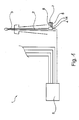
- Fig. 1 is a transmitting antenna system 1 with a transmission power of at least 2 kW and with a monitoring of an electrical conductivity property of the transmitting antenna system 1 refer.
- the transmitting antenna system 1 has a first transmitting antenna 3, which is supplied via a power transport path 2 with signals to be emitted via the first transmitting antenna 3.
- the supply of the first transmitting antenna 3 with the signals to be emitted takes place from a transmitter 8.
- the infrastructure of the first transmitting antenna 3 for monitoring a electrical line property of the transmitter a built-in part 4, which is arranged in the illustrated embodiment of the transmitting antenna system 1, for example in the casing of the power transport path 2.
- the resistance measuring device 5 has a DC voltage source 6 and a resistance measuring device 7. Starting from the transmitter 8, in addition to the wiring leading to the first transmission antenna 3, four further cables are shown, which extend to other antennas, which extend into Fig. 1 but not shown.
- Fig. 2 schematically is an embodiment of a built-in part 4 with at least one coupling of a resistance measuring device in a power transmission path of a transmitting antenna system with a transmission power of at least 2 kW to take.
- Fig. 2 is to take a housing 21 within which a Gleichstromeinspeiseglied (22) is arranged.
- the DC infeed member has a first contact element 12 for coupling to the transmitter, a second contact element 13 for coupling to the power transport path, and a third contact element 14.
- the third contact element 14 serves to connect a DC voltage source and / or a measuring device for determining the resistance.
- a device combination is connected, which has a DC voltage source and / or a measuring device for determining the resistance.
- a commercially available insulation measuring device is connected to the third contact element 14.
- a DC voltage for energizing the power transport path is fed to the power transport path via the DC feed member 22 located in the fixture 4.
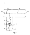
- Fig. 3 is an embodiment of a built-in part 4 with at least one coupling of a resistance measuring device 5 in a power transport path 2 of a transmitting antenna system with a transmission power of at least 2 kW.
- the mounting part 4 is designed as a compact part, which is arranged completely in a housing 21.
- the built-in part 4 comprises in the embodiment shown a direct current injection element whose design is shown in the circuit diagram shown within the housing 21.
- the DC feed member has a first contact element 12 and a second contact element 13.
- the first contact element 12 is provided for the connection of the built-in part 4 with a transmitting side, in the embodiment shown with a transmitting system, the transmitting antenna system.
- the transmitting side of the transmitting antenna system is connected to a power transport path 2 which is connected to the second contact element 13 with the built-in part.
- the power transport path 2 starting from the contact made, leads to at least one first transmitting antenna 3.
- the first connecting line 10 has an isolating capacitor 20, which capacitively couples the transmitting station and the power transport path. The capacitive coupling ensures that the first connection line is permeable to the alternating current, which is used for the transport of the transmission signal. In contrast to a transport of a direct current, the first connecting line via the isolating capacitor 20, however, is largely blocked, so that, for example, a feeding of interference signals in the power transport path is avoided.
- a second connecting line 11 is arranged on the side of the separating capacitor 20, which faces the second contact element 13, a second connecting line 11 is arranged.
- the second connection line 11 connects the power-transport-side section of the first connection line 10 and the infrastructure connected to the second contact element 13 to the third contact element 14.
- the third contact element 14 is provided for the intended coupling of the resistance measuring device in the power transport path.
- a coupling member 9 is arranged for coupling the resistance measuring device in the power transport path.
- the coupling member 9 is formed as a parallel arrangement of a capacitor and a coil. The connection of the coupling member 9 with the third contact element 14 via a transition capacitor 15.
- a surge arrester 19 is formed as part of the Gleichstromeinspeiseglieds parallel to the third contact element 14.
- the surge arrester is disposed within a RF-neutral space 16.
- the surge arrester is designed in the embodiment shown as a gas discharge surge arrester.
- the gas discharge surge arrester It is able to neutralize electromagnetic pulses of natural origin, such as direct or indirect lightning strikes, and thereby keep them away from the connected equipment.
- the neutralization of electromagnetic pulses from the connected devices is formed by the arrangement of the surge arrester 19 within the RF neutral space 16 and by the electrostatic separation of the remaining components of the Gleichstromeinspeiseglieds by means of a transition capacitor 15 in a particularly efficient manner.
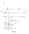
- Fig. 4 shows a further embodiment of a built-in part 4 with at least one coupling of a resistance measuring device 5 in a power transport path 2 of a transmitting antenna system.
- the transmitting antenna system has a transmission power of at least 2 kW.
- a fitting 4 modified to the effect that the connection of the second contact element 13 with the third contact element 14 via a coupling member 9, which in contrast to the embodiment of Fig. 4 is formed as a ⁇ / 4 stub.
- the ⁇ / 4 stub line is connected to the high-frequency resonance of the connected to the third contact element in the Fig. 4 Not shown first transmitting antenna 3 and adapted to this leading power transport path.
- the ⁇ / 4 stub is an empty line, by means of which the circuit targeted a reactance is provided.
- an insulation measuring device is connected to the third contact element 14, which provides for simultaneous application of the direct current voltage to the power transport path 2 and measurement of the ohmic resistance of the power transfer subjected to the DC voltage.
- a stationary insulation meter of the type ST 2383 Sourcetronic GmbH, Fahrenheltstrasse 1, D-28359 Bremen, with an adjustable measuring voltage between 10 V and 1000 V and an isomeas of 100 kOhm and 10 TOhm with an adjustable signal window can be used.
- An evaluation can be made via an acoustic signal with a binary output of a signal below a previously defined and set limit value.
- a triggering and / or an evaluation of the measured data can take place via an interface interface RS 232.
- the measuring cycle is adjustable.
- FIG. 5 Another embodiment of a built-in part 4 with coupling at least one resistance measuring device 5 is Fig. 5 refer to.
- the design of the Fig. 5 is in its basic arrangement of the formation of the Gleichstromeinspeiseglieds the embodiment of a component of the Fig. 3 comparable.
- Fig. 5 In addition to the positional orientation of the components to each other, there is a significant difference Fig. 5 to the embodiment of Fig. 3 in the embodiment of the first contact element 12 and the second contact element 13.
- the first contact element 12 and the second contact element 13 are in the Fig. 5 to be removed embodiment designed as sockets.
- the capacitor 10 is formed to improve the capacitive separation of the first contact element 12 and the second contact element 13 as a ceramic plate.
- the ceramic plate shown for example, has a capacity of at least 500 micro-rat.
- the in the Fig. 5 The embodiment shown corresponds in its design, for example, a stirrup connector, as used in many cases at a feed line beginning of a transmitting antenna system, in which the resistance measuring device is arranged integrated.
Abstract
Die vorliegende Erfindung betrifft eine Sendeantennenanlage (1) mit einer Sendeleistung von wenigstens 2 kW mit einer Überwachung einer elektrischen Leitungseigenschaft der Sendeantennenanlage, wobei die Sendeantennenanlage (1) wenigstens einen Leistungstransportpfad (2) zur Leistungszufuhr zu wenigstens einer ersten Sendeantenne (3) sowie wenigstens eine Widerstandsmesseinrichtung (5) zur Bestimmung eines ohmschen Widerstands zur Überwachung der Sendeantennenanlage (1) aufweist, wobei die Widarstandsmesseinrichtung (5) wenigstens eine Gleichspannungsquelle (6) zur Beaufschlagung wenigstens eines Abschnitts des Leistungstransportpfads (2) mit einer Messgleichspannung sowie wenigstens ein Messgerät (7) zur Bestimmung eines ohmschen Widerstands bezüglich zumindest des mit der Mesegleichspannung beaufschlagten Abschnitts aufweist.The present invention relates to a transmitting antenna system (1) with a transmission power of at least 2 kW with monitoring of an electrical line characteristic of the transmitting antenna system, wherein the transmitting antenna system (1) has at least one power transport path (2) for supplying power to at least one first transmitting antenna (3) and at least one resistance measuring device (5) for determining an ohmic resistance for monitoring the transmitting antenna system (1), wherein the Widarstandsmesseinrichtung (5) at least one DC voltage source (6) for applying at least a portion of the power transport path (2) having a DC measurement voltage and at least one measuring device (7) for determining an ohmic resistance with respect to at least the portion applied with the DC voltage measurement.
Description
Die Erfindung betrifft eine Sendeantennenanlage mit einer Sendeleistung von wenigstens 2 kW mit einer Überwachung einer elektrischen Leitungseigenschaft der Sendeantennenanlage. Des Weiteren wird ein Einbauteil mit zumindest einer Einkopplung einer Widerstandsmesselnrichtung in einen Leistungstransportpfad einer solchen Sendeantennenanlage vorgeschlagen.The invention relates to a transmitting antenna system with a transmission power of at least 2 kW with a monitoring of an electrical line characteristic of the transmitting antenna system. Furthermore, a built-in component with at least one coupling of a resistance-measuring device direction into a power transport path of such a transmitting antenna system is proposed.
Sendeantennenanlagen mit einer Sendeleistung von wenigstens 2 kW werden beispielsweise in der terrestrischen Rundfunksendetechnik genutzt. Beispiele hierfür sind Sendeantennenanlagen, welche für das Versenden von Rundfunkprogrammen In den Frequenzbereichen UKW, DAB und teilweise auch die DVB-T genutzt werden. Sendeantennenanlagen dieser Beispiele weisen wenigstens eine Sendeantenne, in den meisten Fällen auch eine Mehrzahl von Sendeantennen auf. Zur Erhöhung der Reichweite des eingangs genannten Sendeantennenanlagetyps sind die Sendeantennen häufig in hohen Bauwerken untergebracht, wie beispielsweise in Funktürmen.Transmitting antenna systems with a transmission power of at least 2 kW are used for example in terrestrial broadcasting technology. Examples include transmitting antenna systems, which are used for the broadcasting of radio programs in the frequency ranges FM, DAB and partly also the DVB-T. Transmitting antenna systems of these examples have at least one transmitting antenna, in most cases also a plurality of transmitting antennas. To increase the range of the above-mentioned transmission antenna system type, the transmission antennas are often housed in tall structures, such as in radio towers.
Bei den bekannten Sendeantennenanlagen ergibt sich das Problem, dass im Laufe der Zeit Änderungen der elektrischen Leitungseigenschaften der Gesamtanlage sich ergeben können. Insbesondere können elektrischen Leitungseigenschaften des Leistungstransportpfadwerks auftreten, mittels welchen das Sendesignal von einer Sendeanlage zu der Sendeantenne beziehungsweise den Sendeantennen geführt werden. Beispielsweise kann sich durch Eintritt von Feuchtigkeit, Luftspaltsbildung, Rosteffekte oder Ähnliches eine zumindest lokal deutliche Erhöhung eines ohmschen Wirkwiderstands der Sendeantennenanlage ergeben. Eine hierdurch bewirkte. Umsetzung von Hochfrequenzleistung in Wärme kann unter ungünstigen Umständen einen Brandherd herbeiführen und hierdurch eine Beschädigung der Gesamtanlage bis hin zur Zerstörung bewirken, womit nicht zuletzt erhebliche Kosten einhergehen können.In the known transmission antenna systems there is the problem that over time changes in the electrical line properties of the entire system can result. In particular, electrical conduction properties of the power transport pathway may occur, by means of which the transmission signal is fed from a transmission system to the transmission antenna or the transmission antennas. For example, the occurrence of moisture, air gap formation, rust effects or the like can result in an at least locally significant increase in an ohmic resistance of the transmitting antenna installation. One caused thereby. Implementation of high-frequency power in heat can cause a source of fire under unfavorable circumstances and thereby cause damage to the entire system up to destruction, which can entail considerable costs, not least.
Die Erfindung liegt die Aufgabe zu Grunde, die Sicherheit der Sendeantennenanlage, insbesondere hinsichtlich drohender Beschädigung durch Brandherde, zu erhöhen.The invention is based on the object of increasing the safety of the transmitting antenna system, in particular with regard to imminent damage caused by sources of fire.
Die Aufgabe wird mit einer Sendeantennenanlage mit einer Sendeleistung von wenigstens 2 kW mit einer Überwachung einer elektrischen Leitungseigenschaft der Sendeantennenanlage nach Anspruch 1 und mit einem Einbauteil mit zumindest einer Einkopplung einer Widerstandsmesseinrichtung in einen Leistungstransportpfad der Sendeantennenanlage mit einer Sendeleistung von wenigstens 2 kW nach Anspruch 13 gelöst. Des Weiteren wird die Aufgabe mit einem Verfahren zur Überwachung einer elektrischen Leitungseigenschaft einer Sendeantennenanlage mit einer Sendeleistung von wenigstens 2 kW nach Anspruch 19 gelöst. Weitere vorteilhafte Ausgestaltungen und Weiterbildungen gehen aus der nachfolgenden Beschreibung hervor. Ein oder mehrere Merkmale aus den Ansprüchen, der Beschreibung wie auch den Figuren können mit ein oder mehreren weiteren Merkmalen der Offenbarung zu zusätzlichen weiteren Ausgestaltungen der Erfindung verknüpft werden. Insbesondere können auch ein oder mehrere Merkmale aus den unabhängigen Ansprüchen durch ein oder mehrere andere Merkmale aus der Beschreibung und/oder den Figuren ersetzt werden. Die vorgeschlagenen Ansprüche sind vorzugsweise nur als ein Entwurf zur Formulierung des Gegenstands aufzufassen, ohne diesen aber zu beschränken.The object is with a transmitting antenna system with a transmission power of at least 2 kW with a monitoring of an electrical line property of the transmitting antenna system according to
Es wird eine Sendeantennenanlage mit einer Sendeleistung von wenigstens 2 kW mit einer Überwachung einer elektrischen Leitungseigenschaft der Sendeantennenanlage vorgeschlagen.It is proposed a transmitting antenna system with a transmission power of at least 2 kW with a monitoring of an electrical conductivity property of the transmitting antenna system.
Die Sendeantennenanlage weist wenigstens einen Leistungstransportpfad zur Leistungszufuhr zu wenigstens einer ersten Sendeantenne sowie wenigstens eine Widerstandsmesseinrichtung zur Bestimmung eines ohmschen Widerstands auf zur Überwachung der Sendeantennenanlage.The transmitting antenna system has at least one power transport path for supplying power to at least one first transmitting antenna and at least one resistance measuring device for determining an ohmic resistance for monitoring the transmitting antenna system.
Die Widerstandsmesseinrichtung umfasst wenigstens eine Gleichspannungsquelle zur Beaufschlagung wenigstens des Abschnitts des Leistungstransportpfads mit einer Messgleichspannung. Des Weiteren weist die Widerstandsmesseinrichtung wenigstens ein Messgerät zur Bestimmung des Widerstands des Abschnitts auf, der mit der Messgleichspannung beaufschlagt ist.The resistance measuring device comprises at least one DC voltage source for acting on at least the portion of the power transport path with a DC measuring voltage. Furthermore, the resistance measuring device has at least one measuring device for determining the resistance of the section which is subjected to the measuring direct voltage.
In einer besonders bevorzugten Ausgestaltung kann die vorgeschlagene Überwachung bei Sendeleistungen bis zu 50 kW, vorzugsweise von vorzugsweise 2 kW bis 50 kW funktionsfähig genutzt werden.In a particularly preferred embodiment, the proposed monitoring at transmit power up to 50 kW, preferably from preferably 2 kW to 50 kW can be used operationally.
Bei einem Messgerät zur Bestimmung des Widerstands kann es sich um ein Ohmmeter handeln, es kann jedoch ebenfalls zusätzlich oder alternativ beispielsweise vorgesehen sein, dass ein Messgerät vorgesehen ist, welches eine indirekte Bestimmung eines Widerstands vorsieht. So kann zum Beispiel eine Redundanzmessung vorgesehen sein, beispielsweise zum Abgleich und/oder zum Gegenprüfen, Beispielsweise kann eine indirekte Bestimmung über eine Ermittlung eines elektrischen Stroms und/oder einer elektrischen Spannung vorgesehen sein.A measuring device for determining the resistance may be an ohmmeter, but it may also be additionally or alternatively provided, for example, that a measuring device is provided which provides an indirect determination of a resistance. Thus, for example, a redundancy measurement may be provided, for example for adjustment and / or for cross-checking Determination of a determination of an electrical current and / or an electrical voltage to be provided.
In einer Ausgestaltung der Sendeantennenanlage kann beispielsweise vorgesehen sein, dass die Widerstandsmesseinrichtung in einem elektrischen Speiseleitungsbereich des Leistungstransportpfads angeordnet ist.In one embodiment of the transmitting antenna system, it can be provided, for example, that the resistance measuring device is arranged in an electrical feed line region of the power transport path.
Der Speiseleitungsbereich des Leistungstransportpfad bezeichnet einen Bereich der Sendeantennenanlage, welcher vorzugsweise als ein HF-Kabel oder als ein HF-Kabelbündel ausgebildet ist, welches zu der ersten Sendeantenne in führt.The power line section of the power transport path designates a portion of the transmitting antenna system, which is preferably formed as an RF cable or as an RF cable bundle leading to the first transmitting antenna.
In einer bevorzugten Ausgestaltung der Sendeantennenanlage kann beispielsweise vorgesehen sein, dass die Widerstandsmesseinrichtung an bzw. in einem HF-Kabel oder an bzw. in einem Verrohrungsabschnitt des Leistungstransportpfads angeordnet ist.In a preferred embodiment of the transmitting antenna system, it can be provided, for example, that the resistance measuring device is arranged on or in an HF cable or on or in a casing section of the power transport path.
Ein Vorteil einer Anordnung der Widerstandsmesseinrichtung an bzw. in einem HF-Kabel oder an bzw. in einem Verrohrungsabschnitt des Leistungstransportpfads ist beispielsweise, dass durch die unmittelbare Anordnung an die bereits bestehende Infrastruktur der Sendeantennenanlage ein kostengünstiges Anbringen der Widerstandsmesseinrichtung möglich ist, während diese gleichzeitig effizient funktioniert und flexibel positioniert werden kann. So kann eine Widerstandsmesseinrichtung zum Beispiel versetzbar angeordnet werden. Eine weitere Ausgestaltung sieht beispielswiese vor, dass die Widerstandsmesseirichtung nicht permanent eingebaut ist. Vielmehr kann gemäß einer Ausgestaltung diese vollständig oder zumindest teilweise nur zeitweise ein- bzw. angeordnet im Leistungstransportpfad angeordnet sein. So kann zum Beispiel mittels einer transportablen Überprüfungseinrichtung eine Überprüfung des Leistungstransportpfades erfolgen bzw. eine Überprüfung der permanent eingebauten Überwachung des Leistungstransportpfads gemäß des hier beschriebenen Systems erfolgen.An advantage of an arrangement of the resistance measuring device on or in an RF cable or on a piping section of the power transport path is, for example, that a cost-effective attachment of the resistance measuring device is possible due to its direct arrangement with the already existing infrastructure of the transmitting antenna system while at the same time being efficient works and can be flexibly positioned. For example, a resistance measuring device may be arranged to be displaceable. A further embodiment provides, for example, that the resistance measuring device is not permanently installed. Rather, according to one embodiment, these can be arranged completely or at least partially only temporarily or arranged in the power transport path. Thus, for example, by means of a transportable checking device, a check of the power transport path can take place or a check can be made of the permanently installed monitoring of the power transport path according to the system described here.
In einer bevorzugten Ausgestaltung der Sendeantennenanlage kann beispielsweise vorgesehen sein, dass die Widerstandsmesseinrichtung an einem Speiseleitungsbeginn angeordnet ist.In a preferred embodiment of the transmitting antenna system can be provided, for example, that the resistance measuring device is arranged at a feed line beginning.
Eine Anordnung der Widerstandsmesseinrichtung an einem Speiseleitungsbeginn hat insbesondere den Vorteil zur Folge, eine vollständige Überwachung der jenseits des Speiseleitungsbeginns befindlichen Infrastruktur gegen Veränderung des Widerstands ermöglichen zu können. So wird insbesondere eine vollständige Überwachung des Leistungstransportpfads sowie der Sendeantenne gegen Veränderung des Widerstands ermöglicht.An arrangement of the resistance measuring device at a feed line beginning in particular has the advantage of being able to enable a complete monitoring of the infrastructure located beyond the feed line beginning to change the resistance. Thus, in particular, a complete monitoring of the power transport path and the transmitting antenna against change in resistance allows.
In einer Ausgestaltung der Sendeantennenanlage kann beispielsweise vorgesehen sein, dass die Widerstandsmesseinrichtung in einem bestückbaren Schaltfeld des Speiseleitungsbeginns angeordnet Ist.In one embodiment of the transmitting antenna system, it can be provided, for example, that the resistance measuring device is arranged in a pluggable switching field of the feed line beginning.
Ein Einbringen der Widerstandsmesseinrichtung in einem bestückbaren Schaltfeld des Speiseleitungsbeginns hat den Vorteil zur Folge, dass das eine flexible Bestückung der Sendeantennenanlage möglich ist.An introduction of the resistance measuring device in an equipable switching field of the feed line start has the advantage that the flexible assembly of the transmitting antenna system is possible.
Des Weiteren hat ein Einbringen der Widerstandsmesseinrichtung in einem bestückbaren Schaltfeld des Speiseleitungsbeginn den Vorteil, dass bereits zur Verfügung stehende, zum Einbringen in das Schaltfeld vorgesehene Bauteile mit der integrierten Widerstandsmesseinrichtung dahingehend modifiziert und genutzt werden können, dass die vorhandene Infrastruktur ansonsten weitgehend unverändert genutzt werden kann.Furthermore, introducing the resistance measuring device into an equipable switching field of the feed line start has the advantage that already provided components provided for introduction into the switching field can be modified and used with the integrated resistance measuring device such that the existing infrastructure can otherwise be used largely unchanged ,
Gleichzeitig ergibt sich hierdurch der Vorteil, dass am Speiseleitungsbeginn des Leistungstransportpfads der Sendeantennenanlage die Widerstandsmesseinrichtung positioniert ist, was aus den eingangs genannten Gründen vorteilhaft ist. Ein weiterer Vorteil ist, dass die in der Sendetechnik üblichen Schaltfelder verwendet werden können, welche zu Beginn einer jeden Speiseleitung in Richtung zu den Sendeantennenanlage installiert sind. Derartige Schaltfelder sind in vielen Fällen mit so genannten Bügelsteckern bestückt.At the same time, this results in the advantage that the resistance measuring device is positioned at the feed line beginning of the power transport path of the transmitting antenna system, which is advantageous for the reasons stated at the outset. Another advantage is that the usual in the transmission technology panels can be used, which are installed at the beginning of each feed line towards the transmitting antenna system. Such panels are equipped in many cases with so-called strap connectors.
Hierbei kann auch beispielsweise vorgesehen sein, dass mehr als ein Bügelstecker in paralleler Anordnung genutzt werden.In this case, it can also be provided, for example, that more than one ironing plug can be used in a parallel arrangement.
Bei der in Rundfunksendeantennenanlagen oftmals verwendeten Nutzung zweier Halbantennen für ein gleiches Frequenzspektrum kann vorgesehen sein, für jede der Halbantennen eine eigens vorgesehene Widerstandsmesseinrichtung und/oder ein eigens vorgesehenes Gleichstromeinspeiseglied zu verwenden.In the case of the use of two half antennas for a same frequency spectrum, which is often used in broadcast antenna systems, provision may be made for each of the half antennas to use a dedicated resistance measuring device and / or a dedicated DC feed element.
Gleichzeitig kann vorgesehen sein, dass die Widerstandsmesseinrichtung vollständig oder teilweise in einem Bügelstecker eingebaut ist, der zumindest ein Gleichstromeinspeiseglied aufweist.At the same time it can be provided that the resistance measuring device is completely or partially installed in a U-shaped plug, which has at least one GleichstromeinspeIseglied.
In einer Ausgestaltung der Sendeantennenanlage kann beispielsweise vorgesehen sein, dass die Widerstandsmesseinrichtung ein Gleichstromeinspeiseglied aufweist.In one embodiment of the transmitting antenna system, it may be provided, for example, that the resistance measuring device has a direct current injection element.
In einer Ausgestaltung der Sendeantennenanlage, in welcher die Widerstandsmesseinrichtungen ein Gleichstromeinspeiseglied aufweist, kann der Leistungstransportpfad der Sendeantennenanlage, welcher während des Betriebs für den Transport von Hochfrequenzleistungen vorgesehen ist, mit einem Gleichstrom beaufschlagt werden.In one embodiment of the transmitting antenna system, in which the resistance measuring devices has a direct current injection element, the power transmission path of the transmitting antenna system, which is provided during operation for the transport of high-frequency power, be subjected to a direct current.
In einer Ausbildung der Sendeantennenanlage kann beispielsweise vorgesehen sein, dass das Gleichstromeinspeiseglied ein erstes Kontaktelement und ein zweites Kontaktelement aufweist. Es kann des Weiteren vorgesehen sein, dass das erste Kontaktelement und das zweite Kontaktelement beispielsweise mittels wenigstens eines Kondensators kapazitiv gekoppelt sind.In one embodiment of the transmitting antenna system, it can be provided, for example, that the direct current feeding element has a first contact element and a second contact element. It may further be provided that the first contact element and the second contact element are capacitively coupled, for example by means of at least one capacitor.
Bei einer Anordnung des Gleichstromeinspeiseglieds zwischen der Sendeanlage und dem Leistungstransportpfad bewirkt die kapazitive Kopplung, dass die zu transportierende HF-Leistung weiterhin zwischen Sendeanlage und Leistungstransportpfad passieren kann, der Pfad für einen Gleichstrom jedoch aufgrund der kapazitiver Kopplung gesperrt ist.In an arrangement of the DC feed member between the transmitter and the power transport path, the capacitive coupling causes the RF power to be transported to continue to pass between the transmitter and the power transport path, but the path for a DC power is disabled due to the capacitive coupling.
In einer Ausgestaltung der Sendeantennenanlage kann beispielsweise vorgesehen sein, dass von einer ersten Verbindungsleitung des ersten Kontaktelements mit dem zweiten Kontaktelement ausgehend eine zu einem dritten Kontaktelement hinführende zweite Verbindungsleitung angeordnet ist.In one embodiment of the transmitting antenna system, provision can be made, for example, for a second connecting line leading from a first connecting line of the first contact element to the second contact element to lead to a third contact element.
In einer bevorzugten Ausgestaltung der Sendeantennenanlage ist die zweite Verbindungsleitung von einer Seite der ersten Verbindungsleitung ausgehend, welche der Leistungstransportpfadseite des Kondensators zugewandt ist. Hierdurch wird eine Möglichkeit einer Verbindung des Leistungstransportpfads zu einem Ende der zweiten Verbindungsleitung geschaffen, wohingegen eine Verbindung eines Endes der zweiten Verbindungsleitung mit der Sendeanlage über einen Gleichstrom durch die kapazitive Kopplung des ersten Kontaktelements unterbunden ist.In a preferred embodiment of the transmitting antenna system, the second connecting line is starting from one side of the first connecting line, which faces the power transport path side of the capacitor. This creates a possibility of connecting the power transport path to one end of the second connection line, whereas a connection of one end of the second connection line to the transmission system is prevented via a direct current through the capacitive coupling of the first contact element.
In einer Ausgestaltung der Sendeantennenanlage kann beispielsweise vorgesehen sein, dass die zweite Verbindungsleitung wenigstens ein Kopplungsglied des Gleichstromeinspeiseglieds aufweist zur Verbindung des zweiten Kontaktelements mit dem dritten Kontaktelement. Es kann bevorzugt vorgesehen sein, dass das Kopplungsglied als λ/4-Stichleitungs-Anpassung an die Sendeantenne oder als L-C-Parallelschwingkreis ausgebildet ist.In an embodiment of the transmitting antenna system, it can be provided, for example, that the second connecting line has at least one coupling element of the DC infeed element for connecting the second contact element to the third contact element. It can preferably be provided that the coupling member as λ / 4-stub adjustment to the transmitting antenna or as an LC parallel resonant circuit is formed.
Es kann in einer anderen Ausgestaltung auch vorgesehen sein, dass das Kopplungsglied als Drossel ausgebildet ist.It may also be provided in another embodiment that the coupling member is designed as a throttle.
Vorteil eines Einbringens eines Kopplungsglieds, welches als λ/4-Stichleitungs-Anpassung, als L-C-Parallelsehwingkreis oder als Drossel ausgebildet ist, ist unter anderem eine mittels destruktiver Interferenz der zum Leistungstransportpfad führenden Wechselspannung erfolgende Dämpfung in Richtung des Messgerätes und/oder der Gleichspannungsquelle, so dass diese von den Wechselspannung leitenden Bauteilen der Sendeantennenanlage getrennt sind.Advantage of introducing a coupling member, which is designed as a λ / 4-stub adaptation, as an LC parallel oscillating circuit or as a choke, inter alia, takes place by means of destructive interference leading to the power transport path AC voltage attenuation in the direction of the measuring device and / or the DC voltage source, so that they are separated from the AC voltage-conducting components of the transmitting antenna system.
Die Auslegung des Kopplungsglieds bei einer Bandbreite eines von der Sendeantenne emittierten Frequenzbereichs wird beispielweise dahingehend vorgenommen, dass das Kopplungsglied eine Frequenz etwa in der Mitte des Frequenzbereichs filtert. So kann beispielsweise bei einer Ausgestaltung eines Kopplungsglieds als λ/4-Stichleitungs-Anpassung vorgesehen sein, dass bei dem Beispiel einer UKW-Sendeantennenanlage, welche Signale aus einem Frequenzbereich von 87-108 MHz emittiert, eine mittlere Frequenz von f = (87+108) MHz/2 = 97,5 MHz zu Grunde gelegt wird. Aus einer mittleren Frequenz von 97,5 MHz ergibt sich aus der Formel λ = c/f mit den genannten Größen ein Wert von λ = 3,07 m. In der Formel λ = c/f ist c die Lichtgeschwindigkeit und f die oben genannte Frequenz. Unter Nutzung des ermittelten Werts ergibt sich für die λ/4-Stlchleitungs-Anpassung eine notwendige Länge der λ/4-Stichleitungs von 3,07 m/4 = 0,77 m. Bei der Auslegung einer λ/4-Stichleitungs-Anpassung anhand eines Mittelwerts eines Frequenzbereichs haben sich in einem Feldversuch ein Rückflussdämpfungswert von > 21 dB und eine vernachlässigbar kleine Durchgangsdämpfung gezeigt, so dass die bestimmungsgemäße Funktion des Gleichstromeinspeiseglieds in Kombination mit einer isolationsmesseinrichtung gewährleistet war. Gleichzeitig wurden die Übertragungsparameter der emittierten Signale nicht nachweisbar beeinflusst, wodurch die Funktionsfähigkeit der beschriebenen Versuchsanordnung belegt ist.The design of the coupling element at a bandwidth of a frequency range emitted by the transmitting antenna is carried out, for example, in such a way that the coupling element filters a frequency approximately in the middle of the frequency range. Thus, for example, in the case of an embodiment of a coupling element as λ / 4 stub adaptation, it may be provided that in the example of a VHF transmission antenna system which emits signals from a frequency range of 87-108 MHz, an average frequency of f = (87 + 108 ) MHz / 2 = 97.5 MHz. From a mean frequency of 97.5 MHz results from the formula λ = c / f with the sizes mentioned a value of λ = 3.07 m. In the formula λ = c / f, c is the speed of light and f is the above-mentioned frequency. Using the determined value, a necessary λ / 4 branch line length of 3.07 m / 4 = 0.77 m results for the λ / 4 Pipe line adaptation. In the design of a λ / 4-stub adaptation based on an average of a frequency range, a return loss value of> 21 dB and a negligibly small transmission loss were demonstrated in a field test, so that the intended function of the DC infeed was ensured in combination with an insulation measuring device. At the same time, the transmission parameters of the emitted signals were not demonstrably influenced, as a result of which the functionality of the described experimental setup is proven.
In einer Ausgestaltung der Sendeantennenanlage kann beispielsweise vorgesehen sein, dass die zweite Verbindungsleitung einen zwischen dem Kopplungsglied und dem dritten Kontaktelement angeordneten Übergangskondensator des Gleichstromeinspeiseglieds aufweist.In one embodiment of the transmitting antenna system, it can be provided, for example, that the second connecting line has a transition capacitor of the DC feed element arranged between the coupling element and the third contact element.
In einer weiteren Ausgestaltung der Sendeantennenanlage kann vorgesehen sein, dass zwischen dem Kopplungsglied und dem dritten Kontaktelement ein HF-neutraler Raum des Gleichstromeinspeiseglieds angeordnet ist, der bevorzugt einen Gasentladungs-Überspannungsableiter aufweist.In a further embodiment of the transmitting antenna system can be provided that between the coupling member and the third contact element, an RF neutral space of the DC feed member is arranged, which preferably has a gas discharge surge arrester.
In einer weiteren Ausgestaltung der Sendeantennenanlage kann vorgesehen sein, dass die Widerstandsmesseinrichtung ein mit der Anlage verbundenes, bevorzugt austauschbares und/oder steckbares, Einbauteil aufweist, das zumindest das Gleichstromeinspeiseglied enthält.In a further embodiment of the transmitting antenna system, it can be provided that the resistance measuring device has a built-in, preferably exchangeable and / or pluggable, built-in component which contains at least the direct-current injection element.
Der Vorteil sowohl des Übergangs-Kondensators und/oder des Gasentladungsüberspannungsableiters ist, dass eine Zerstörung einzelner Bauteile durch spontane Spannungserhöhung, beispielsweise durch direkten oder indirekten folgenden Blitzschlag, weitgehend vermieden wird.The advantage of both the transition capacitor and / or the gas discharge surge arrester is that destruction of individual components by spontaneous increase in voltage, for example by direct or indirect subsequent lightning strike, largely avoided.
in einer weiteren Ausgestaltung der Sendeantennenanlage kann beispielsweise vorgesehen sein, dass zumindest ein Kontaktelement der Widerstandsmesseinrichtung, bevorzugt alle Kontaktelemente, als Steckbuchse ausgebildet sind, wobei:
- eine erste Steckbuchse mit der Sendeanlage verbunden ist,
- eine zweite Steckbuchse mit dem Leistungstransportpfad verbunden ist und
- eine dritte Steckbuchse, die bevorzugt mit einer Abschirmung versehen ist, zum Schutz vor einem Kontakt mit Gegenständen oder Lebewesen, zumindest mit der Gleichspannungsquelle verbunden ist.
- a first socket is connected to the transmitter,
- a second socket is connected to the power transport path and
- a third socket, which is preferably provided with a shield, is connected to protect against contact with objects or living beings, at least with the DC voltage source.
Bevorzugt weist die isolationsmesseinrichtung die Gleichspannungsquelle und das Messgerät zur Bestimmung des Widerstands auf. In Verbindung mit wenigstens dem Gleichstromeinspeiseglied bildet die Steckverbindung des Gleichstromeinspeiseglieds mit der Isolationsmesseinrichtung beispielsweise die Widerstandsmesseinrichtung.The insulation measuring device preferably has the DC voltage source and the measuring device for determining the resistance. In conjunction with at least the dc feed member, the connector of the dc feed member with the insulation measuring means forms, for example, the resistance measuring means.
Ebenfalls kann auch vorgesehen sein, dass anstelle einer, beispielsweise kompakt ausgebildeten, Isolationsmesseinrichtung eine Kombination wenigstens einer Gleichstromquelle und wenigstens eines Messgerätes an der dritten Steckbuchse angeordnet ist.It can also be provided that, instead of a, for example, compact, insulation measuring device, a combination of at least one DC power source and at least one measuring device is arranged on the third plug socket.
Ebenfalls kann auch vorgesehen sein, dass die Widerstandsmesseinrichtung gebildet wird, in dem mehr als eine Gleichstromquelle und mehr als ein Messgerät an der dritten Steckbuchse angeordnet sind.It can also be provided that the resistance measuring device is formed in which more than one DC power source and more than one measuring device are arranged on the third plug socket.
Ebenfalls sind auch Ausgestaltungen möglich, in welcher das Gleichstromeinspeiseglied, die Gleichstromquelle und/oder das Messgerät in einem kompakten Bauteil angeordnet sind.Embodiments are also possible in which the DC feed element, the DC source and / or the measuring device are arranged in a compact component.
Eine Verbindung mit der ersten Steckbuchse, mit der zweiten Steckbuchse und/oder der dritten Steckbuchse kann revisibel lösbar sein, was insbesondere den Vorteil hat, dass die Widerstandsmesseinrichtung oder Bestandteile der Widerstandsmesseinrichtung austauschbar sind.A connection with the first socket, with the second socket and / or the third socket can be revisibly solvable, which in particular has the advantage that the resistance measuring device or components of the resistance measuring device are interchangeable.
In einer weiteren Ausgestaltung kann beispielsweise vorgesehen sein, dass das Gleichstromeinspeiseglied als ein kompaktes Bauteil vorgesehen ist, und dass das Gleichstromeinspeiseglied als austauschbares Einbauteil vorliegt.In a further embodiment, for example, it may be provided that the DC feed member is provided as a compact component, and that the DC feed member is present as an exchangeable built-in component.
Ebenfalls kann beispielsweise vorgesehen sein, dass eine Verbindung der dritten Steckbuchse mit der Gleichstromquelle und/oder dem Messgerät oder aber eine Verbindung der dritten Steckbuchse mit der isolationsmesseinrichtung als nicht zerstörungsfrei lösbar ausgeführt ist, beispielsweise als Schweißverbindung.It can also be provided, for example, that a connection of the third socket to the DC power source and / or the measuring device or a connection of the third socket with the insulation measuring device is designed as non-destructive releasable, for example, as a welded connection.
Es kann beispielsweise eine Messgleichspannung mit einem Wert zwischen 500 V und 1500 V vorgesehen sein.For example, a DC measurement voltage with a value between 500 V and 1500 V can be provided.
Bevorzugt kann eine Messgleichspannung mit einem Wert zwischen 750 und 1250 V vorgesehen sein. Auch können unterschiedliche Messgleichspannungen zum Einsatz kommen, die vorzugsweise innerhalb des angegebenen Bereichs liegen.Preferably, a DC measurement voltage with a value between 750 and 1250 V can be provided. Also, different measured DC voltages can be used, which are preferably within the specified range.
In einer weiteren Ausgestaltung der Sendeantennenanlage kann beispielsweise vorgesehen sein, dass die Sendeantennenanlage eine Funkantennenanlage ist.In a further embodiment of the transmitting antenna system, it can be provided, for example, that the transmitting antenna system is a radio antenna system.
Ein weiterer Gedanke der Erfindung, der abhängig wie auch unabhängig von der oben beschriebenen Sendeantennenanlage angewendet werden kann, betrifft ein Einbauteil.Another aspect of the invention, which can be used depending as well as independently of the transmitting antenna system described above, relates to a built-in part.
Es ist ein Einbauteil mit zumindest einer Einkopplung einer Widerstandsmesseinrichtung in einen Leistungstransportpfad einer Sendeantennenanlage mit einer Sendeleistung von wenigstens 2 kW vorgesehen, wobei das Einbauteil wenigstens ein Gleichstromeinspeiseglied aufweist, das umfasst:
- ein bevorzugt als erste Steckbuchse ausgebildetes erstes Kontaktelement zum, bevorzugt senderseitigen, Verbinden,
- ein bevorzugt als zweite Steckbuchse ausgebildetes zweites Kontaktelement zum, bevorzugt leistungstransportseitigen, Verbinden und
- ein bevorzugt als dritte Steckbuchse ausgebildetes drittes Kontaktelement zum Verbinden mit der Widerstandsmesseinrichtung.
- a preferably designed as a first socket first contact element for, preferably transmitter-side, connecting,
- a preferably designed as a second socket second contact element for, preferably power transport side, connecting and
- a preferably designed as a third socket third contact element for connecting to the resistance measuring device.
Die Widerstandsmesseinrichtung weist bevorzugt eine Isolationsmesseinrichtung auf.The resistance measuring device preferably has an insulation measuring device.
Es kann des Weiteren beispielsweise ein Einbauteil vorgesehen sein, dessen erstes Kontaktelement und zweites Kontaktelement mittels wenigstens eines Kondensators des Gleichstromeinspeiseglieds kapazitiv gekoppelt sind.Furthermore, for example, a built-in part may be provided, whose first contact element and second contact element are capacitively coupled by means of at least one capacitor of the DC infeed element.
In einer Ausgestaltung des Einbauteils kann beispielsweise vorgesehen sein, dass von einer ersten Verbindungsleitung des Gleichstromeinspeiseglieds zwischen dem ersten Kontaktelement und dem zweiten Kontaktelement ausgehend, bevorzugt leistungstransportseitig des Kondensators orientiert, eine zu dem dritten Kontaktelement hinführende zweite Verbindungsleitung des Gleichstromeinspeiseglieds angeordnet ist.In one embodiment of the installation part, it can be provided, for example, that starting from a first connection line of the DC infeed element between the first contact element and the second contact element, preferably power transmission side of the capacitor, a second connecting line of the DC infeed member leading to the third contact element is arranged.
In einer weiteren Ausbildung des Einbauteils kann ein Kopplungsglied vorgesehen sein, dass als Teil der zweiten Verbindungsleitung vorgesehen ist. Das Kopplungsglied ist bevorzugt als λ/4-Stichleitungs-Anpassung an die Sendeantenne und/oder als L-C-Parallelschwingkreis ausgebildet.In a further embodiment of the installation part, a coupling element may be provided, which is provided as part of the second connection line. The coupling element is preferably designed as a λ / 4 stub line adaptation to the transmitting antenna and / or as an L-C parallel resonant circuit.
In einer weiteren Ausgestaltung ist beispielsweise vorgesehen, dass die zweite Verbindungsleitung einen zwischen dem Kopplungsglied und dem dritten Kontaktelement angeordneten Übergangskondensator aufweist und dass zwischen dem Übergangskondensator und dem dritten Kontaktelement ein HF-neutraler Raum des Gleichstromeinspeiseglieds angeordnet ist, der bevorzugt einen Überspannungsableiter aufweist.In a further refinement, it is provided, for example, that the second connecting line has a transition capacitor arranged between the coupling element and the third contact element and that an HF-neutral space of the DC infeed element is arranged between the transition capacitor and the third contact element, which preferably has a surge arrester.
In einer Ausbildung des Einbauteils ist beispielsweise vorgesehen, dass das dritte Kontaktelement eine zweipolige Steckbuchse mit einem ersten Pol und einem zweiten Pol ist, wobei einer der beiden Pole ein Erdungspol ist.In one embodiment of the installation part, it is provided, for example, that the third contact element is a two-pole socket with a first pole and a second pole, one of the two poles being a grounding pole.
In einer Ausbildung des Einbauteils ist beispielsweise vorgesehen, dass ein Widerstandsmessgerät an das Einbauteil austauschbar angeordnet ist.In one embodiment of the installation part, it is provided, for example, that a resistance measuring device is arranged exchangeably on the installation part.
Ein weiterer Gedanke der Erfindung, der abhängig wie unabhängig von der oben beschriebenen Sendeantennenanlage angewendet werden kann, betrifft ein Verfahren zur Überwachung einer elektrischen Leitungseigenschaft einer Sendeantennenanlage mit einer Sendeleistung von wenigstens 2 kW.Another aspect of the invention, which can be applied depending on how independent of the transmitting antenna equipment described above, relates to a method for Monitoring an electrical line characteristic of a transmitting antenna system with a transmission power of at least 2 kW.
Es ist ein Verfahren zur Überwachung einer elektrischen Leitungseigenschaft einer Sendeantennenanlage mit einer Sendeleistung von wenigstens 2 kW vorgesehen. Die Sendeantennenanlage weist wenigstens einen Leistungstransportpfad und wenigstens eine erste Sendeantenne auf.A method is provided for monitoring an electrical line characteristic of a transmitting antenna installation with a transmission power of at least 2 kW. The transmitting antenna system has at least one power transport path and at least one first transmitting antenna.
Zur Überwachung wird wenigstens ein Abschnitt des Leistungstransportpfads mit einer Messgleichspannung beaufschlagt und eine ohmsche Widerstandsbestimmung wenigstens des Abschnitts des Leistungstransportpfads vorgenommen,For monitoring purposes, at least one section of the power transport path is subjected to a DC measurement voltage and an ohmic resistance determination of at least the section of the power transport path is made.
In einer Ausgestaltung des Verfahrens erfolgt die ohmsche Widerstandsbestimmung zeitabhängig.In one embodiment of the method, the ohmic resistance determination is time-dependent.
In einer bevorzugten Ausbildung des Verfahren wird bei Unterschreiten eines festgesetzten Schwellenwertes des ohmschen Widerstands, bevorzugt bei Unterschreiten eines ohmschen Widerstandswerts zwischen von 100 kOhm und 500 kOhm, besonders bevorzugt bei Unterschreiten eines ohmschen Widerstandswerts zwischen von 150 kOhm und 250 kOhm, ein Alarmsignal ausgegeben.In a preferred embodiment of the method, an alarm signal is output when falling below a set threshold value of the ohmic resistance, preferably when falling below an ohmic resistance value between 100 kOhm and 500 kOhm, particularly preferably falls below an ohmic resistance value between 150 kOhm and 250 kOhm.
Die genannten Werte sind hierbei niedrig genug, um etwaige Fehlalarme durch eine wetterbedingte Absenkung der Widerstandswerte, beispielsweise aufgrund von hoher Luftfeuchte und/oder salzhaltiger Luft, zu vermeiden.The values mentioned here are low enough to avoid any false alarms due to weather-related lowering of the resistance values, for example due to high air humidity and / or salty air.
Bevorzugt erfolgt die ohmsche Widerstandsbestimmung mit einer gesteuerten Widerstandsbestimmung in kontinuierlicher Weise oder zu vorbestimmten Zeitpunkten.Preferably, the ohmic resistance determination is carried out with a controlled resistance determination in a continuous manner or at predetermined times.
Es kann des Weiteren eine Verwendung einer Sendeantennenanlage zum überwachten Betrieb einer Fernmeldeanlage unter durchgehender oder planmäßig wiederkehrender Isolationsmessung mittels Beaufschlagung wenigstens eines Abschnitts des Leistungstransportpfads der Sendeantennenanlage mit einer Messgleichspannung und einer ohmschen Widerstandsbestimmung des Abschnitts des Leistungstransportpfads vorgesehen sein.Furthermore, a use of a transmitting antenna installation for the monitored operation of a telecommunication system with continuous or regularly recurring insulation measurement can be provided by applying at least a portion of the power transport path of the transmitting antenna installation with a DC measuring voltage and an ohmic resistance determination of the section of the power transport path.
Beispielsweise kann vorgesehen sein, dass Messungen in äquidistanten Abständen vorgenommen werden. Hierzu ist nicht notwendigerweise eine aktive Regelung notwendig, sondern eine Steuerung kann nach einem zuvor festgelegten Zeitplan erfolgen.For example, it can be provided that measurements are made at equidistant intervals. An active control is not necessarily necessary for this, but a control can take place according to a predetermined schedule.
Zur Gewährleistung der gewünschten Funktionsfähigkeit hat sich eine Vornahme von Messungen in Zeitabständen von mehreren Stunden als vollkommen ausreichend erwiesen. Für eine einzelne Messung kann eine vorgenommene Messdauer von wenigen Sekunden bereits völlig ausreichend sein, um ein aussagekräftiges Ergebnis zu erlangen.To ensure the desired functionality, making measurements at intervals of several hours has proven to be perfectly adequate. For a single measurement, a measurement period of just a few seconds may already be sufficient to obtain a meaningful result.
Es kann beispielsweise vorgesehen sein, dass Messungen in einem Zeitabstand von N Stunden zwischen einer i-ten Messung und einer (i+1)-ten Messung erfolgen, wobei i eine positive natürliche Zahl ist, die als Laufindex genutzt wird. Die Zahl N kann hierbei eine positive Dezimalzahl zwischen 2 und 10, bevorzugt zwischen 4 und 8, besonders bevorzugt zwischen 5 und 7 sein.For example, it may be provided that measurements are taken at an interval of N hours between an ith measurement and an (i + 1) th measurement, where i is a positive natural number used as a running index. The number N here can be a positive decimal number between 2 and 10, preferably between 4 and 8, particularly preferably between 5 and 7.
Diese genannten Zeitabstände und Messdauern sind für den gewünschten Zweck ausreichend, da dem Schadensfall eine oft tagelang oder gar wochenlang zu beobachtende Reduktion des gemessenen Widerstands vorhergehen.These mentioned time intervals and measuring periods are sufficient for the desired purpose, since the damage is preceded by a reduction of the measured resistance, which can often be observed for days or even weeks.
Das Messergebnis kann zum Beispiel direkt vor Ort angezeigt werden. Auch besteht die Möglichkeit, dass das Messergebnis übertragen wird, beispielweise über ein Bussystem. Beispielsweise kann eine Fernübertragung vorgesehen sein, die eine Überwachung fernab von der Sendeanlage ermöglicht. Dieses kann zum Beispiel ein zentrales Überwachungszentrum sein, welches in der Lage ist, eine Mehrzahl an Sendeanlagen, Sendemasten und Funktürme an unterschiedlichen Orten zu überwachen. Vorzugsweise erfolgt die Überwachung computergesteuert. Eine Messung kann dadurch nicht nur überwacht sondern auch computergesteuert ausgelöst werden. Darüber hinaus besteht die Möglichkeit, die Messung manuell auszulösen. Vorzugsweise werden die Messergebnisse gespeichert und können automatisiert ausgewertet werden, zum Beispiel statistisch ausgewertet werden. Beispielweise kann darüber eine Instandsetzung getriggert werden, insbesondere eine vorausschauende Überprüfung, bevor ein größerer Schaden entstehen kann.The measurement result can be displayed directly on site, for example. There is also the possibility that the measurement result is transmitted, for example via a bus system. For example, a remote transmission may be provided, which allows monitoring far away from the transmitter. This may be, for example, a central monitoring center capable of monitoring a plurality of transmitters, towers and towers at different locations. Preferably, the monitoring is computer controlled. As a result, a measurement can not only be monitored but also triggered by computer control. In addition, it is possible to trigger the measurement manually. Preferably, the measurement results are stored and can be evaluated automatically, for example, be evaluated statistically. For example, a repair may be triggered by this, in particular a foresighted check before major damage can occur.
Weiterhin kann ein Funkturm mehrere derartige Überwachungen entlang des Leistungstransportpfads verteilt aufweisen, vorzugsweise hintereinander in größeren Abständen zueinander entlang des Pfads. Dieses ermöglicht nicht nur zum Beispiel die gesamte Messung des Leistungstransportpfads. Vielmehr besteht die Möglichkeit, durch jeweilige Messung ein oder mehrere Fehlerstellen besser entlang des Leistungstransportpfads lokalisieren zu können. So kann zum Beispiel über einen Abgleich mit einer Referenzmessung eine Abweichung detektiert werden. Beginnt die Messung mit einer Überwachung, die am nächsten zur Sendeantenne angeordnet ist, aber dort noch keine oder nur geringste Abweichungen zur Referenzmessung vorliegen, kann dann durch die Messung an der nächsten, weiter entfernt von der Sendeantenne angeordneten Überwachung sodann dabei festgestellt werden, ob sich eine Abweichung außerhalb einer Toleranz eingestellt hat. So kann immer weitergehend die Prüfung erfolgen, bis schließlich darüber eien Abweichung zum ersten Mal außerhalb der Toleranz liegt. Dadurch lässt sich die Fehlersteile eingrenzen, was die Arbeiten zum Beispiel in einem Funkturm erleichtert.Furthermore, a radio tower may have a plurality of such monitors distributed along the power transport path, preferably one behind the other at greater distances from each other along the path. This not only allows, for example, the entire measurement of the power transport path. Rather, it is possible by respective Measurement to locate one or more fault locations better along the power transport path. Thus, for example, a deviation can be detected via a comparison with a reference measurement. If the measurement starts with a monitoring that is closest to the transmitting antenna, but there are no or only slight deviations from the reference measurement, it can then be determined by the measurement at the next monitoring, further away from the transmitting antenna, whether set a deviation outside a tolerance. Thus, the test can be carried out more and more, until finally there is a deviation for the first time out of tolerance. As a result, the error parts can be limited, which facilitates the work, for example, in a radio tower.
Weitere vorteilhafte Ausgestaltungen und Weiterbildungen gehen aus den nachfolgenden Figuren hervor. Die aus den Figuren hervorgehenden Einzelheiten und Merkmale sind jedoch nicht auf diese beschränkt. Vielmehr können ein oder mehrere Merkmale mit ein oder mehreren Merkmalen aus der obigen Beschreibung zu neuen Ausgestaltung verknüpft werden. Insbesondere dienen die nachfolgenden Ausführungen nicht als Beschränkung des jeweiligen Schutzbereiches, sondern erläutern einzelne Merkmale sowie Ihr mögliches Zusammenwirken untereinander.Further advantageous embodiments and developments will become apparent from the following figures. However, the details and features of the figures are not limited to these. Rather, one or more features having one or more features from the above description may be linked to new design. In particular, the following statements do not serve as a limitation of the respective scope, but explain individual features and their possible interaction with each other.
Es zeigen:
- Fig. 1:
- Eine Prinzipskizze einer Sendeantennenanlage mit einer Überwachung einer elektrischen Leitungseigenschaft der Sendeantennenanlage;
- Fig. 2:
- eine Prinzipskizze einer beispielhaften Ausgestaltung eines Einbauteils mit einer Einkopplung einer Widerstandsmesseinrichtung;
- Fig. 3:
- eine Prinzipskizze einer beispielhaften Ausgestaltung eines Einbauteils mit einer Einkopplung einer Widerstandsmesseinrichtung;
- Fig. 4:
- eine Prinzipskizze einer weiteren beispielhaften Ausgestaltung eines Einbauteils mit einer Einkopplung einer Widerstandsmesseinrichtung;
- Fig. 5:
- eine Prinzipskizze einer weiteren beispielhaften Ausgestaltung eines Einbauteils mit einer Einkopplung einer Widerstandsmesseinrichtung.
- Fig. 1:
- A schematic diagram of a transmitting antenna system with a monitoring of an electrical conductivity property of the transmitting antenna system;
- Fig. 2:
- a schematic diagram of an exemplary embodiment of a mounting part with a coupling of a resistance measuring device;
- 3:
- a schematic diagram of an exemplary embodiment of a mounting part with a coupling of a resistance measuring device;
- 4:
- a schematic diagram of another exemplary embodiment of a fitting with a coupling of a resistance measuring device;
- Fig. 5:
- a schematic diagram of another exemplary embodiment of a fitting with a coupling of a resistance measuring device.
Auf der Seite des Trennkondensators 20 angeordnet, weiche dem zweiten Kontaktelement 13 zugewandt ist, ist eine zweite Verbindungsleitung 11 angeordnet. Die zweite Verbindungsleitung 11 verbindet den leistungstransportseitigen Abschnitt der ersten Verbindungsleitung 10 sowie die über das zweite Kontaktelement 13 an dieses angeschlossene Infrastruktur mit dem dritten Kontaktelement 14. Das dritte Kontaktelement 14 ist für die beabsichtigte Einkopplung der Widerstandsmesseinrichtung in den Leistungstransportpfad vorgesehen. Zur Einkopplung der Widerstandsmesseinrichtung in den Leistungstransportpfad ist ausgehend von der ersten Verbindungsleitung 10 hin zum dritten Kontaktelement 14 in der gezeigten Ausgestaltung des Einbauteils 4 zum ersten ein Kopplungsglied 9 angeordnet. Das Kopplungsglied 9 Ist als Parallelanordnung eines Kondensators und einer Spule ausgebildet. Die Verbindung des Kopplungsglieds 9 mit dem dritten Kontaktelement 14 erfolgt über einen Übergangskondensator 15. Des Weiteren ist parallel zu dem dritten Kontaktelement 14 ein Überspannungsableiter 19 als Bestandteil des Gleichstromeinspeiseglieds ausgebildet Der Überspannungsableiter ist innerhalb eines HF-neutralen Raums 16 angeordnet. Der Überspannungsableiter ist in der gezeigten Ausgestaltung als Gasentladungsüberspannungsableiter ausgebildet. Der Gasentladungsüberspannungsableiter Ist in der Lage, elektromagnetische Impulse insbesondere natürlichen Ursprungs, wie direkte oder indirekte Blitzschläge, zu neutralisieren und hierdurch von den angeschlossenen Geräten fernzuhalten. Die Neutralisierung elektromagnetischer Impulse von den angeschlossenen Geräten wird durch die Anordnung des Überspannungsableitung 19 innerhalb des HF-neutralen Raums 16 und durch die elektrostatische Trennung von den übrigen Bauteilen des Gleichstromeinspeiseglieds mittels eines Übergangs Kondensator 15 in besonders effizienter Weise ausgebildet.Arranged on the side of the separating
In einer Ausgestaltung kann beispielsweise vorgesehen sein, dass an dem dritten Kontaktelement 14 ein Isolationsmessgerät angeschlossen wird, welches ein gleichzeitiges Beaufschlagen des Leistungstransportpfads 2 mit der Gleichspannung und ein Messen des Ohmschen Widerstands des mit der Gleichspannung beaufschlagten Leistungstransport vorsieht.In one embodiment, it may be provided, for example, that an insulation measuring device is connected to the
Beispielsweise kann ein stationäres Isolationsmessgerät des Typs ST 2383 der Firma Sourcetronic GmbH, Fahrenheltstrasse 1, D-28359 Bremen, mit einer einstellbaren Messpannung zwischen 10 V und 1000 V und einem Isomessbereich von 100 kOhm und 10 TOhm mit einem einstellbaren Signalfenster genutzt werden. Eine Auswertung kann über ein akustisches Signal mit einer binären Ausgabe eines Signals bei einem Unterschreiten eines zuvor definierten und eingestellten Grenzwertes erfolgen. Ein Ansteuern und/oder ein Auswerten der Messdaten kann über eine Interface-Schnittstelle RS 232 erfolgen. Der Messzyklus ist einstellbar.For example, a stationary insulation meter of the type ST 2383 Sourcetronic GmbH,
Eine weitere Ausgestaltung eines Einbauteils 4 mit Einkopplung zumindest einer Widerstandsmesseinrichtung 5 ist
Claims (21)
wobei die Sendeantennenanlage (1) wenigstens einen Leistungstransportpfad (2) zur Leistungszufuhr zu wenigstens einer ersten Sendeantenne (3) sowie wenigstens eine Widerstandsmesseinrichtung (5) zur Bestimmung eines ohmschen Widerstands zur Überwachung der Sendeantennenanlage (1) aufweist,
wobei die Widerstandsmesseinrichtung (5) wenigstens eine Gleichspannungsquelle (6) zur Beaufschlagung wenigstens eines Abschnitts des Leistungstransportpfads (2) mit einer Messgleichspannung sowie wenigstens ein Messgerät (7) zur Bestimmung eines ohmschen Widerstands bezüglich zumindest des mit der Messgleichspannung beaufschlagten Abschnitts aufweist.Transmitting antenna system (1) with a transmission power of at least 2 kW with a monitoring of an electrical line characteristic of the transmitting antenna system,
wherein the transmitting antenna system (1) has at least one power transport path (2) for supplying power to at least one first transmitting antenna (3) and at least one resistance measuring device (5) for determining an ohmic resistance for monitoring the transmitting antenna system (1),
wherein the resistance measuring device (5) has at least one DC voltage source (6) for applying at least one section of the power transport path (2) with a DC measuring voltage and at least one measuring device (7) for determining an ohmic resistance with respect to at least the section loaded with the DC measuring voltage.
zur Überwachung wenigstens ein Abschnitt des Leistungstransportpfads (2) mit einer Messgleichspannung beaufschlagt wird und eine ohmsche Widerstandsbestimmung wenigstens des Abschnitts des Leistungstransportpfads (2) erfolgt.Method for monitoring an electrical line characteristic of a transmitting antenna installation (1) having a transmission power of at least 2 kW and having at least one power transport path (2) and at least one first transmitting antenna (3)
for monitoring at least a portion of the power transport path (2) is subjected to a DC measurement voltage and an ohmic resistance determination of at least the portion of the power transport path (2).
Applications Claiming Priority (1)
| Application Number | Priority Date | Filing Date | Title |
|---|---|---|---|
| DE102013014476.0A DE102013014476A1 (en) | 2013-09-02 | 2013-09-02 | Transmitting antenna system with a monitoring of an electrical conductivity property and built-in part with a coupling of a resistance measuring device |
Publications (1)
| Publication Number | Publication Date |
|---|---|
| EP2848950A1 true EP2848950A1 (en) | 2015-03-18 |
Family
ID=51535303
Family Applications (1)
| Application Number | Title | Priority Date | Filing Date |
|---|---|---|---|
| EP14003004.0A Withdrawn EP2848950A1 (en) | 2013-09-02 | 2014-09-01 | Radio antenna installation with surveillance of an electrical property of a cable and a build-in part coupling a resistance measuring unit into it |
Country Status (2)
| Country | Link |
|---|---|
| EP (1) | EP2848950A1 (en) |
| DE (1) | DE102013014476A1 (en) |
Families Citing this family (1)
| Publication number | Priority date | Publication date | Assignee | Title |
|---|---|---|---|---|
| EP3224902B1 (en) * | 2014-11-25 | 2020-03-18 | Media Broadcast GmbH | Monitoring apparatus for a transmitting antenna system and method for monitoring a transmitting antenna system |
Citations (8)
| Publication number | Priority date | Publication date | Assignee | Title |
|---|---|---|---|---|
| US2637533A (en) * | 1949-09-24 | 1953-05-05 | Andrew Corp | Multi-v fm antenna |
| US4286238A (en) * | 1978-12-29 | 1981-08-25 | Thomson-Csf | Harmonic filtering device for radio transmitter |
| US20030223160A1 (en) * | 2002-05-31 | 2003-12-04 | Henry Pixley | Ground fault circuit interrupter for coaxial drop cable and method of operation |
| JP2004085355A (en) * | 2002-08-27 | 2004-03-18 | Hitachi Cable Ltd | Temperature measurement device and temperature monitoring system |
| GB2454236A (en) * | 2007-11-02 | 2009-05-06 | Stanelco Rf Technologies Ltd | Radio frequency cable monitor |
| JP2010010841A (en) * | 2008-06-24 | 2010-01-14 | Toyota Motor Corp | Wireless communication device |
| WO2010108330A1 (en) * | 2009-03-27 | 2010-09-30 | Siemens Aktiengesellschaft | Radio communication system and method for communication between base station and antenna |
| WO2012060414A1 (en) * | 2010-11-02 | 2012-05-10 | 矢崎総業株式会社 | High voltage testing device |
Family Cites Families (2)
| Publication number | Priority date | Publication date | Assignee | Title |
|---|---|---|---|---|
| DE3013755A1 (en) * | 1980-04-10 | 1981-10-15 | geb. Jacob Ursula 4330 Mülheim Nies | Testing motor car aerials - by comparing electrical measurement values with design values and using yes-no indicator |
| IT1275418B (en) * | 1995-06-02 | 1997-08-05 | Forem Spa | DC POLARIZER FOR HIGH RF POWER AND LOW INTERMODULATION |
-
2013
- 2013-09-02 DE DE102013014476.0A patent/DE102013014476A1/en not_active Withdrawn
-
2014
- 2014-09-01 EP EP14003004.0A patent/EP2848950A1/en not_active Withdrawn
Patent Citations (9)
| Publication number | Priority date | Publication date | Assignee | Title |
|---|---|---|---|---|
| US2637533A (en) * | 1949-09-24 | 1953-05-05 | Andrew Corp | Multi-v fm antenna |
| US4286238A (en) * | 1978-12-29 | 1981-08-25 | Thomson-Csf | Harmonic filtering device for radio transmitter |
| US20030223160A1 (en) * | 2002-05-31 | 2003-12-04 | Henry Pixley | Ground fault circuit interrupter for coaxial drop cable and method of operation |
| JP2004085355A (en) * | 2002-08-27 | 2004-03-18 | Hitachi Cable Ltd | Temperature measurement device and temperature monitoring system |
| GB2454236A (en) * | 2007-11-02 | 2009-05-06 | Stanelco Rf Technologies Ltd | Radio frequency cable monitor |
| JP2010010841A (en) * | 2008-06-24 | 2010-01-14 | Toyota Motor Corp | Wireless communication device |
| WO2010108330A1 (en) * | 2009-03-27 | 2010-09-30 | Siemens Aktiengesellschaft | Radio communication system and method for communication between base station and antenna |
| WO2012060414A1 (en) * | 2010-11-02 | 2012-05-10 | 矢崎総業株式会社 | High voltage testing device |
| EP2642306A1 (en) * | 2010-11-02 | 2013-09-25 | Yazaki Corporation | High voltage testing device |
Also Published As
| Publication number | Publication date |
|---|---|
| DE102013014476A1 (en) | 2015-03-05 |
Similar Documents
| Publication | Publication Date | Title |
|---|---|---|
| DE69820101T2 (en) | SURGE SUPPRESSION DEVICE | |
| DE102011079935B4 (en) | Monitoring device for a cable sleeve and cable sleeve with monitoring device | |
| EP1708239B1 (en) | Vacuum plasma generator | |
| EP3139188B1 (en) | Method and device for isolation troubleshooting with adaptive test current determination | |
| DE2413345A1 (en) | INSULATED PIPING SYSTEM, IN PARTICULAR AN UNDERGROUND PIPING SYSTEM FOR DISTRICT HEATING | |
| EP2427940A1 (en) | Monitoring apparatus | |
| WO2014057017A1 (en) | Line network, in particular an on-board dc electrical system for a motor vehicle, and method for monitoring a line network for the occurrence of an arc | |
| EP1090303B1 (en) | Method and device for monitoring an electrode line of a bipolar high voltage direct current (hvdc) transmission system | |
| DE102013107968A1 (en) | Online monitoring system for use in electrical installations and method of operation thereof | |
| EP4127744A1 (en) | Electrical circuit | |
| EP2848950A1 (en) | Radio antenna installation with surveillance of an electrical property of a cable and a build-in part coupling a resistance measuring unit into it | |
| EP2375543B1 (en) | Method for monitoring an energy transmission line, noise suppression by repeated data transmission | |
| DE102006045083A1 (en) | Rail vehicle with a fire detection device | |
| DE102006020029B4 (en) | Adaptive, capacitive coupling circuit and method for message transmission via shielded power cables of an electrical power distribution network | |
| EP3224902B1 (en) | Monitoring apparatus for a transmitting antenna system and method for monitoring a transmitting antenna system | |
| DE202014100207U1 (en) | Coupler for medium voltage powerline communication | |
| EP1285282B1 (en) | Method and device for detecting accidental arcs | |
| DE102018219959A1 (en) | Method and measuring arrangement for fault detection on electrical lines | |
| EP3269015B1 (en) | Method for determining states and locating faults in installed isolated down conductors in the external lightning protection means | |
| DE19515068A1 (en) | Arrangement for partial discharge detection in high voltage cables and connection elements | |
| AT516165B1 (en) | Detecting the unauthorized removal of grounding conductors | |
| DE102022117038B3 (en) | Method for monitoring a protective conductor of a supply network and a correspondingly configured monitoring device | |
| DE202014011102U1 (en) | Electrical switching device with a built-in connection system for connecting a measuring device and feeding and detecting low-frequency and high-frequency signals | |
| EP3914918B1 (en) | Inspecting sheath voltage limiters | |
| EP2399328A1 (en) | Circuit breaker having detection of the aperiodic current change |
Legal Events
| Date | Code | Title | Description |
|---|---|---|---|
| PUAI | Public reference made under article 153(3) epc to a published international application that has entered the european phase |
Free format text: ORIGINAL CODE: 0009012 |
|
| 17P | Request for examination filed |
Effective date: 20140901 |
|
| AK | Designated contracting states |
Kind code of ref document: A1 Designated state(s): AL AT BE BG CH CY CZ DE DK EE ES FI FR GB GR HR HU IE IS IT LI LT LU LV MC MK MT NL NO PL PT RO RS SE SI SK SM TR |
|
| AX | Request for extension of the european patent |
Extension state: BA ME |
|
| STAA | Information on the status of an ep patent application or granted ep patent |
Free format text: STATUS: THE APPLICATION HAS BEEN WITHDRAWN |
|
| 18W | Application withdrawn |
Effective date: 20150923 |